

Page 1
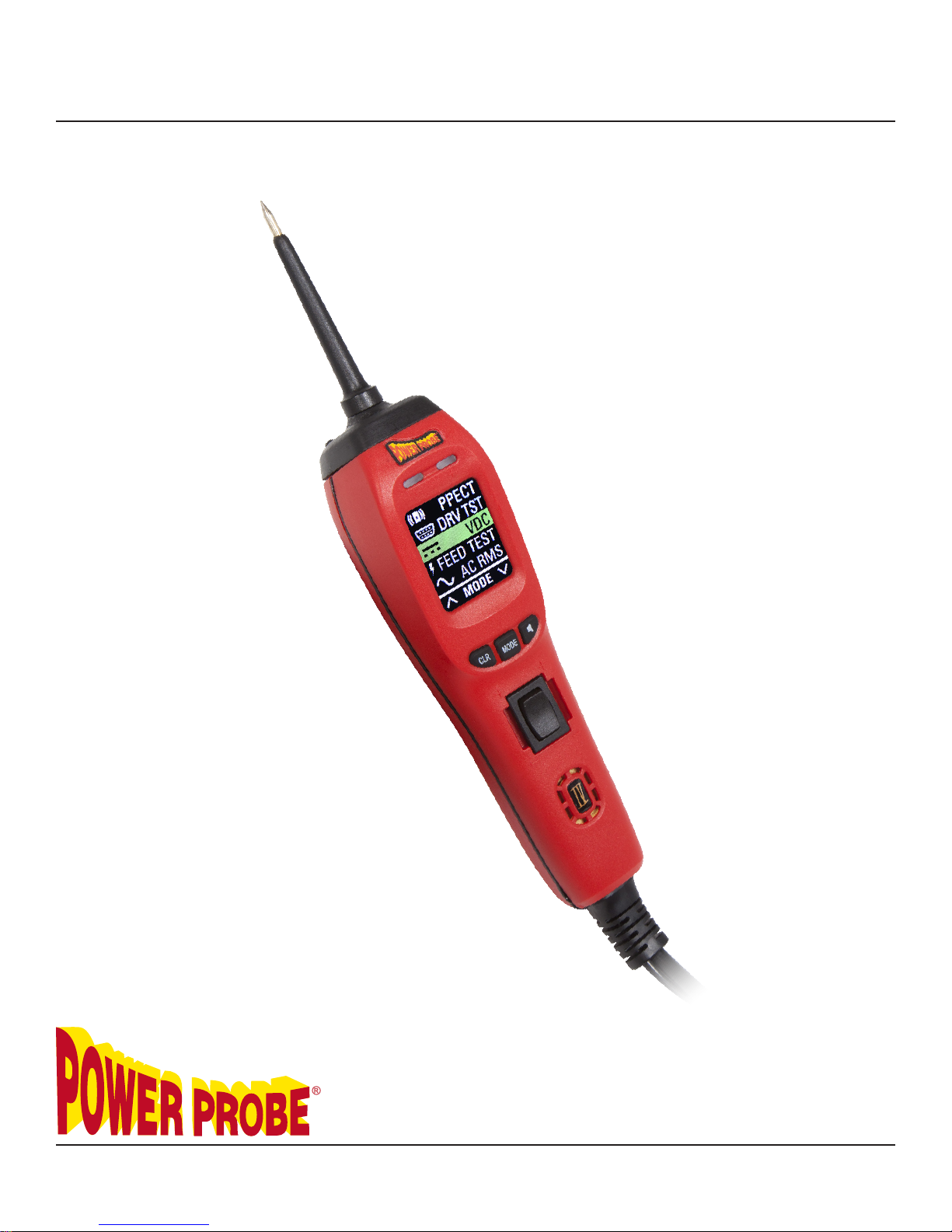
Power Probe IV
Users Manual
www.powerprobe.com · 800-655-3585
The Next Generation of Diagnostics
Page 2

Page 3

Page 1
Power Probe IV
Table of Contents
Introduction .................................................................................. 2
Safety ........................................................................................... 3
Appearance and Controls .......................................................... 4-5
Start Up ........................................................................................ 6
Mode Navigation ........................................................................ 7
Testing and Measuring Operations
• DC Voltage in VDC Mode .............................................................
• Activating Components ..................................................................
• Power Feed Test ..............................................................................
• AC Voltage Measurement (RMS) .................................................
• AC Voltage Measurement (P to P) ................................................
• Frequency Measurement ...............................................................
Advanced Testing Operations
• PPECT Mode ........................................................................ 15
• Fuel Injector Mode .............................................................. 16-17
• Driver Test Mode ................................................................. 18-19
8
9
10-11
12
13
14
Tool Repair Operations ............................................................... 20-21
Specifications ............................................................................... 22
Notes ............................................................................................ 23-24
Warranty ...................................................................................... 25
www.powerprobe.com · 800-655-3585
Page 4
Page 2
Introduction
Power Probe IV
Thank you for purchasing the Power Probe IV Diagnostic Electronic Circuit and Component tester. The Power Probe IV is the
next generation of Power Probe Circuit Testers. Now loaded
with powerful multi-meter functions, advanced diagnostic test
modes, an easy to read color LCD display and a new rugged water and dust resistant housing, the Power Probe IV is
designed to give you years of trouble free testing, even in the
most demanding work environments.
The unique configuration of Power Probe testers gives them
many advantages over using conventional test lights or multimeters for circuit testing.
(1) Since the Power Probe IV is connected to the battery, you
can apply battery power or battery ground directly to the tip of
the tool. You can energize and activate components to verify
their correct operation. This is real dynamic component testing
and the only true way to test an active component.
(2) The Power Probe IV is always connected to the vehicle’s battery, so the tool maintains a permanent connection to the source
power and ground voltage. Circuit voltage checks are quickly
performed with just a single probe connection, unlike using two
meter leads.
(3)Using the PPIV, all your voltage checks are referenced back
to the source battery and account for every connection and
possible voltage drop between the source and the probe tip.
(4) Automatic Voltage Drop Indication - When probing a
circuit, if the voltage measured at the tip is 0.5 volts lower (or
more) than the source battery voltage, the red LED will not Illuminate and no speaker tone will sound. This will instantly alert
you that there is a voltage drop that may need to be investigated or repaired.
www.powerprobe.com · 800-655-3585
Page 5

Page 3
Power Probe IV
Safety
CAUTION - PLEASE READ
To avoid possible electric shock or personal injury and to avoid damage to the Power Probe or
item being tested, please use the Power Probe according to the following safety procedures:
• Power Probe recommends reading this manual before using the Power Probe IV.
• This product is designed to be powered from DC power sources such as found in Automotive, Small Craft Marine and Small Craft Aviation electrical systems and will be damaged if
connected to line voltage such as 115V AC power sources or 24V AC Control circuits.
• Do not connect to electrical system with higher than rated voltage specified in this manual.
• Do not test voltage exceeding the rated voltage on the Power Probe IV.
• When testing voltage exceeding 30V AC RMS, 42V AC Peak, or 60V DC, be particularly
careful to avoid any electric shock.
• Check the Probe IV case for cracks or damage. Damage to the case can leak high voltage
causing a potential electrocution risk.
• Check the Probe IV cables for any insulation damage or bare wires. If damaged, do not use
the tool, please contact Power Probe Technical support.
• Use only shrouded leads and accessories authorized by Power Probe to minimize exposed
conductive electrical connections to eliminate shock hazard.
• Do not open the Power Probe IV, no serviceable parts are inside. Opening the Power Probe
IV voids the warranty. All repairs should only be performed by authorized Power Probe service centers.
• When maintaining the Power Probe, use only replacement parts specified by the manufacturer.
• Use only in well ventilated areas. Do not operate around flammable materials, vapor or
dust.
• Be careful when energizing components that have moving parts, assemblies containing motors or high powered solenoids.
• Power Probe, Inc. shall not be liable for damage to vehicles or components caused by misuse.
• Power Probe, Inc. shall not be held liable for any harm caused by unintentional or intentional
misuse of our products or tools.
• If you have any questions please go to our website www.powerprobe.com or contact Power Probe’s Technical Support: 800-655-3585.
www.powerprobe.com · 800-655-3585
Page 6

Page 4
Power Probe IV
Appearance and Controls
Removable Probe Tip -Uses standard 4mm banana
1
type connector enabling use of different probes, leads,
or extensions.
CLR
H
MODE
H
2
3
4
5
6
7
LED, Green (-) -Will light indicating a path to ground.
More than10Ω resistance and/or more than 0.5 volts
on a ground circuit, the Green LED will not illuminate.
LED, Red (+) -Will light indicating (B+) Battery positive. If the circuit voltage drop is more than 0.5 volts
from battery voltage, the Red LED will not illuminate.
Color Screen - Large Hi-resolution LCD display shows
multiple readings on one screen.
Button, Left; “CLR” Clear / Scroll Up - Used to
clear Min/Max in voltmeter modes or “Scroll Up”
when navigating menus.
Button, Right; “ ” Mute / Scroll Down - Used to
turn the Speaker Tone On/Off or “Scroll Down” when
navigating menus.
Button, Center; “MODE” Select - Used to select a
J
J
8
9
www.powerprobe.com · 800-655-3585
test mode when navigating menus.
Rocker Switch (replaceable) Part #30-00087 When rocker switch is pressed forward(+) battery power(B+) is applied to the probe tip. When rocker switch
is pressed rearward(-) battery ground(B-) is applied to
the probe tip. Can only be used when in either of the
DC voltmeter modes.
Speaker - Distinct tones for power(B+) or ground(B-)
Page 7

Power Probe IV
Appearance and Controls
Page 5
Rear
IP4363215
10
11
12
13
Serial Number
Circuit Breaker
(replaceable)
Part #30-00041
USB Connecter
5 x 20mm 20A
14
Cover
www.powerprobe.com · 800-655-3585
Fast Blow Fuse;
Part #30-00040
Page 8
Page 6
Start-Up
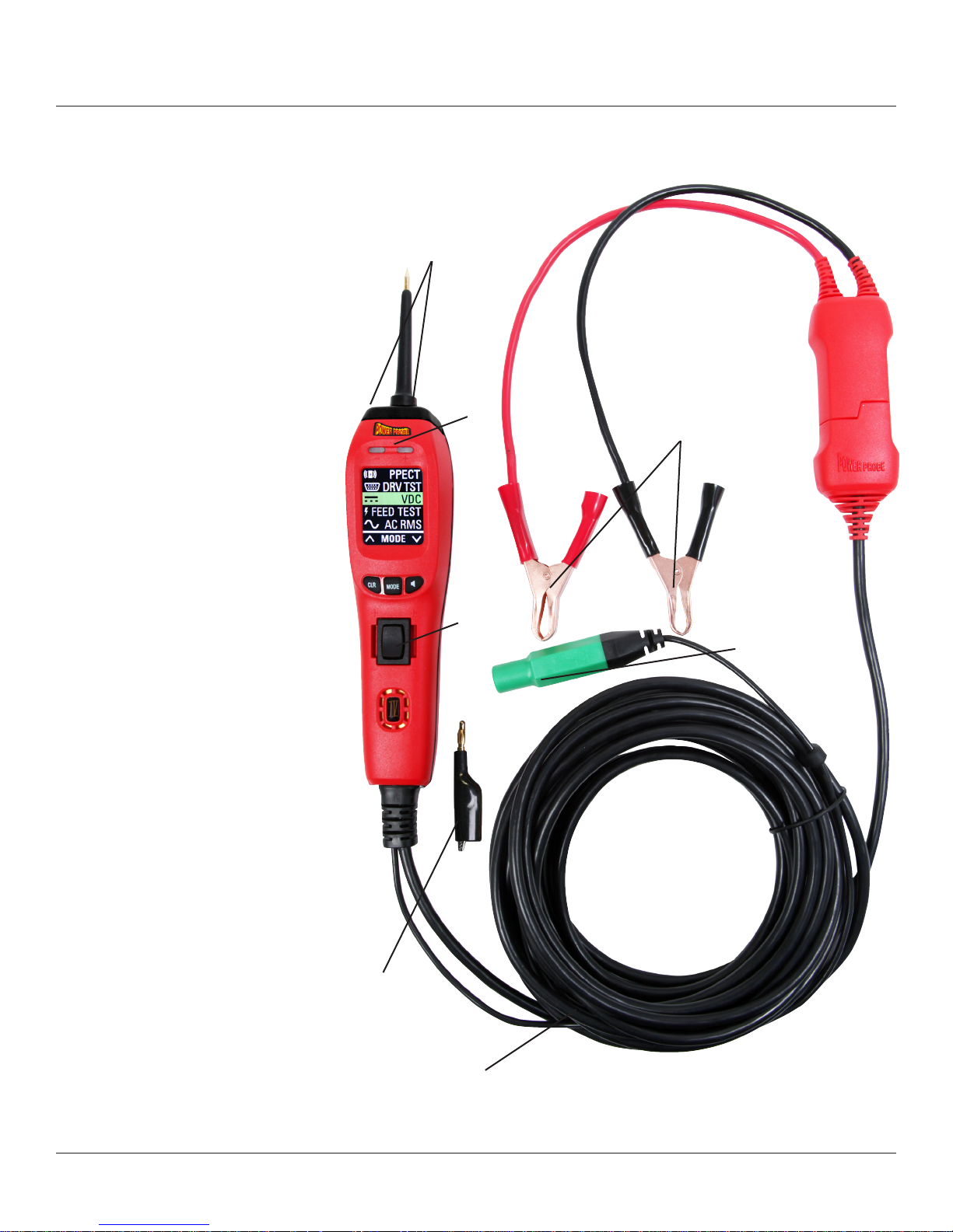
Operating Source Voltage
The Power Probe IV is designed
to connect to and is powered by
12 to 24 VDC electrical systems
and comes supplied with a 23 ft.,
heavy duty power cable and a
Y-connector with 2 battery clips.
Connecting to the Vehicle’s
Battery (Voltage Source)
Connect the red clip to the positive
terminal of the vehicle’s battery
source and the black clip to the
negative or ground terminal. The
Power Probe IV start-up tone will
sound.
Power Probe IV
Flashlight
Red/Green
LEDs
Battery Clips
Auxiliary Ground Lead
The auxiliary ground lead provides
ground to circuits and components
that are not already connected to
ground. It also serves as the negative lead for resistance testing. To
test the auxiliary ground lead, contact the probe tip and the auxiliary
ground lead together. The Green
LED should illuminate. This shows
that the auxiliary ground lead
is working properly. If the green
LED does not illuminate, check the
replaceable 20 amp fuse in the
auxiliary ground lead. The fuse
is for protection in the event the
ground lead inadvertantly contacts
the battery positive.
LED Flashlight
Flashlight is a standard feature on
the Power Probe IV. The two bright
white LEDs are always ON making it possible to see under dashboards and in dark areas.
Alligator Clip
Adapter
23 ft. Power
Lead
Rocker
Switch
Auxiliary
Ground
Lead
www.powerprobe.com · 800-655-3585
Page 9
Page 7
Power Probe IV
Mode Navigation
The Power Probe IV has 8 different test modes available:
1. VDC – For DC voltage measurements. This is the default mode on startup. Max. 200 VDC
2. FEED TEST – For measuring loaded resistance in Ohms and display voltage drop.
3. AC RMS – For AC voltage measurements. Displays a True RMS averaged AC voltage. Max
200 VAC.
4. P-P – For AC voltage measurements. Displays Peak to Peak AC voltage. Max 200 VAC.
5. Hz FRQ CTR – For measuring signal Frequency. Also displays + and - Pulse Width.
6. FUEL INJ – Tests Fuel Injectors and Injector circuits.
7. DRV TST – Supplies safe voltage for testing computer driver circuits.
8. PPECT – Detects the open circuit signal from Power Probe ECT2000 to assist in locating opens.
Refer to sections: Testing and Measuring Operations and Advanced Testing Operations for further
mode descriptions and suggested applications.
CLR
MODE
To Change Mode
CLR
MODE
CLR
MODE
Press
the
“MODE”
button
www.powerprobe.com · 800-655-3585
Scroll up and down
the mode list using
“CLR” for up and
“ ” for down
naviagtion
Press
the
“MODE”
button again
to select
Page 10

Page 8
Power Probe IV
Testing and Measuring Operations
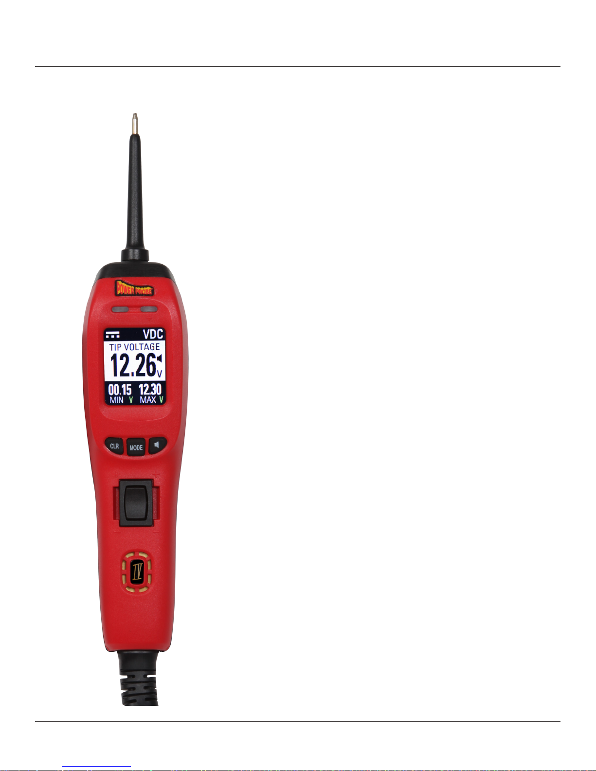
DC Voltage Measurement in VDC Mode
In this mode, you will supply battery power or battery ground to
the tip when pressing the rocker switch
VDC - VDC mode is for testing DC (direct current) voltages.
Voltage testing is as easy as contacting the probe tip to a circuit
and reading the display. The Power Probe IV will display the
probe tip voltage in the center display.
The Power Probe IV automatically enters VDC Mode when first
connected to the vehicle’s battery, or to a 12-24 volt power
supply. VDC Mode is the only mode that the Power Probe IV can
supply battery power or ground by pressing the rocker switch.
If the Probe tip voltage is within 0.5 volts of the source battery
voltage and the circuit resistance is less than 10 Ohms, the Red
LED will illuminate and if the speaker is turned on, the speaker will
make a high-tone.
When testing on ground circuits, as long as there is less than 10
Ohms total circuit resistance from tip to battery ground, the Green
LED will illuminate and the speaker will make a low-tone.
This greatly simplifies testing as the Power Probe IV’s Red/Green LEDs and speaker tones provide
a quick indication if there are excessive voltage drops or circuit resistance. If the LEDs do not illuminate and there is no tone from the speaker, you know instantly there may be a circuit problem.
Minimum and Maximum (MIN/MAX) voltages are shown on the bottom of the display. To reset the
MIN/MAX, press the left “CLR” button beneath the display.
VDC mode has a very high sampling rate that is good for tests where the tech is looking for glitches
or deviations from the main signal. This is a very sensitive mode that can capture even the smallest
voltage spikes or drop-outs without having to use a scope.
The Power Probe IV can safely measure up to 200 VDC.
www.powerprobe.com · 800-655-3585
Page 11

Power Probe IV
Testing and Measuring Operations
Activating Components in VDC Mode
Activating Electrical Components in VDC Mode is one of the main features
that make the Power Probe IV very useful when testing. Being able to apply battery power or ground right to the probe tip gives you the ability to
activate and dynamically test electrical components such as lights, motors,
and solenoids.
You can power up components on the vehicle or on the bench by utilizing
the auxiliary ground lead. This type of dynamic component testing is the
only true method to verify a components correct operation. Testing a part
with a volt-ohmmeter may tell you if the part is out of spec, but you never
really know if the part is good until it is operating under power.
Page 9
Pressing the rocker switch forward supplies battery power to the probe tip.
Pressing the rocker switch rearward supplies battery ground to the probe
tip.
The power output is circuit breaker protected. If the component being
tested draws too much current, or the circuit has a shorted condition, the
Power Probe IV’s circuit breaker will trip protecting the tool and the circuit.
When the circuit
breaker is tripped, the
PPIV display will show
“CIRCUIT BREAKER
RESETTING” and
will automatically
reset itself after a few
seconds.
Pressing the rocker switch in any
other mode will not apply power
or ground and the main screen
will display a large red “X”.
www.powerprobe.com · 800-655-3585
Page 12

Page 10
Power Probe IV
Testing and Measuring Operations
Power Feed Testing
FEED TEST – Power Feed Test (PFT) is used to check
resistance on static circuits or voltage drops on active
circuits by simply probing one connection of the circuit
being tested.
PFT measures total circuit resistance from the source battery accurately whether there is voltage on the circuit or
not, unlike standard multimeters. With the Aux. Ground
lead, PFT can also be used like a standard ohmmeter.
PFT displays both Battery and Tip voltage simultaneously
for easy voltage drop testing.
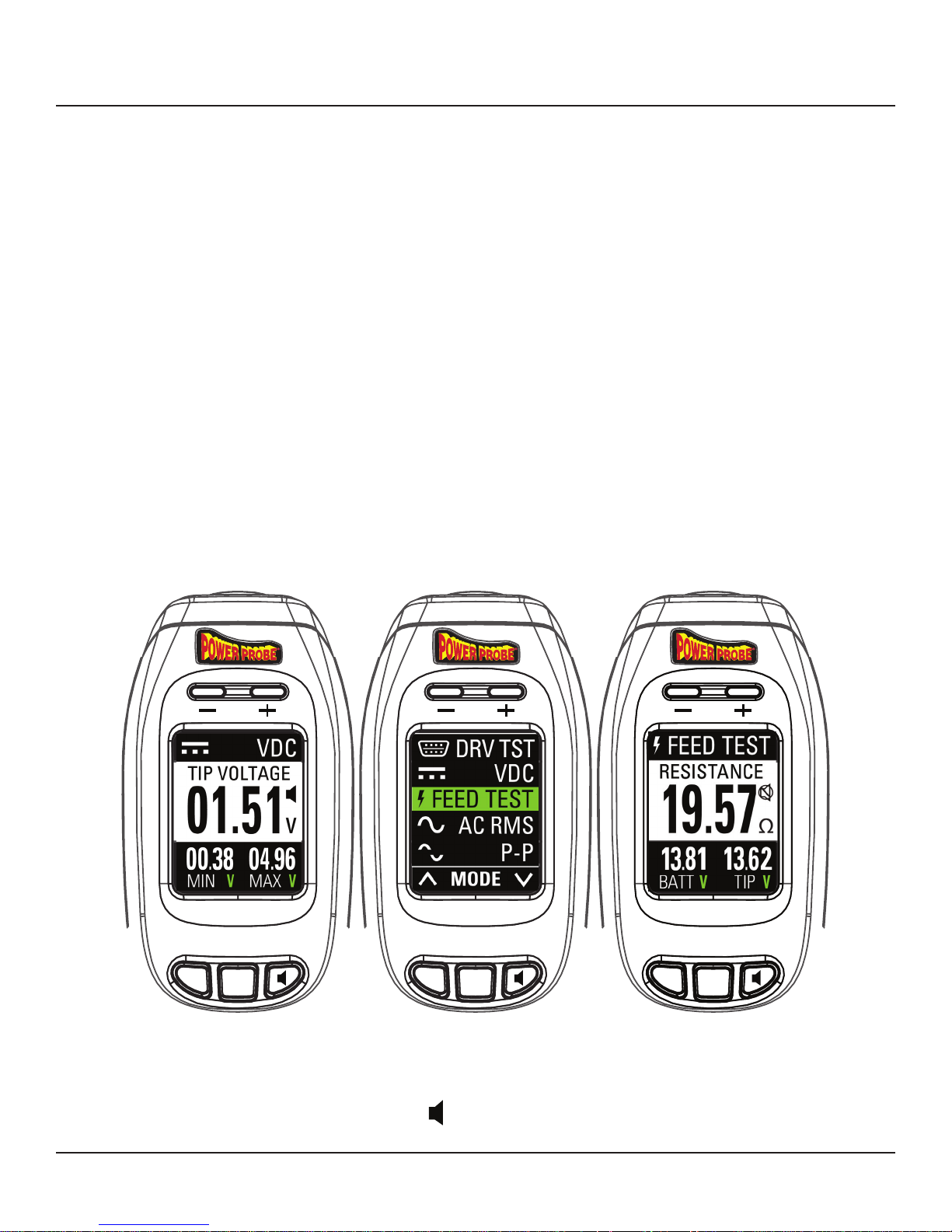
In this mode, the Power Probe IV display will show:
- Total circuit Resistance on the center screen.
1
- Probe Tip Voltage.
2
- Battery Voltage.
3
The battery voltage and the tip voltage are both
displayed along the bottom of the screen for
easy voltage drop testing.
The circuit resistance will be calculated even with voltage applied to the circuit. To accurately test the
power and ground feed resistance, the component must be removed from the circuit first. Simply unplug any component, relay, or module on the circuit, contact the probe tip to the circuit and view the
circuit resistance.
PFT will display battery voltage (BATT V) from the battery clips in the lower left display area, probe
tip (TIP V) voltage in the lower right display area and will provide total circuit resistance readings in
the main area of the display all in one test.
www.powerprobe.com · 800-655-3585
Page 13

Page 11
Power Probe IV
Testing and Measuring Operations
Power Feed Testing
To test, first disconnect the device or load being operated from the circuit, then contact the probe tip
to the circuit being tested. Removing the component from the circuit prevents the component load
from affecting and altering the resistance reading.
For voltage drop testing the component must be connected and observe the difference between
battery voltage (BATT V) and tip voltage (TIP V)
If the circuit resistance is less than 10 Ohms the Red or Green LED will illuminate and the speaker will
make a corresponding tone if the speaker is on. Any differences between battery voltage and tip
voltage are easily observed.
PFT can also be used as an ohmmeter on wire or components not connected to battery power or
ground. Simply connect the item being tested between the probe tip and the auxiliary ground lead
and read the resistance reading in Ohms.
While it is possible to ohm check some components, it should be noted that PFT is primarily for use
on wiring only and should never be connected to a solid state component such as a module.
Remove component from
circuit before performing
Power Feed Test
www.powerprobe.com · 800-655-3585
Page 14

Page 12
Power Probe IV
Testing and Measuring Operations
AC Voltage Measurement (RMS)
AC RMS mode is for measuring AC (alternating
current) voltages and can be used on any AC voltage or
pulsed waveform signal where an RMS averaged voltage
measurement is required.
Contact the probe tip to the circuit and it will display an
RMS averaged AC voltage reading in the main display
area while also displaying RMS Min/Max AC voltages
on the bottom line.
Powering up and activating circuits with the rocker switch
can not be performed in this mode.
Pressing the “CLR” button will reset the Min/Max readings.
AC RMS Voltage is used in the same manner as a standard
DVOM would be used to measure the averaged AC voltage in any circuit that produces AC voltage. This can be
used for, but not limited to, tests such as checking alternator
diode ripple, abs sensors, crank sensors, etc.
The Power Probe IV can safely measure up to 70 VAC.
WARNING
Do not use the Power Probe IV to test AC line voltage, such as a 120V wall plug. Attempting to use
the Power Probe IV on AC line voltage will damage the probe and could cause personal injury.
www.powerprobe.com · 800-655-3585
Page 15

Power Probe IV
Testing and Measuring Operations
AC Voltage Measurement (P to P)
P-P mode can be used on any AC voltage signal where
a Peak to Peak (P-P) voltage measurement is required.
P-P stands for Peak to Peak AC voltage. Where AC RMS
displays an averaged AC voltage, P-P does not average
the reading but displays the total voltage difference from
the lowest to highest voltage extreme on an AC signal.
In this mode, the display will be an AC Voltmeter that shows
the Tip Voltage in the center and the Min/Max voltage
readings along the bottom of the display.
Page 13
The voltage displayed is the total voltage potential between
the lowest and highest voltage sensed on the AC signal being measured.
Powering up and activating circuits with the rocker switch
can not be performed in this mode.
The total Peak to Peak voltage will be shown in the main
display area. The Min voltage will display lowest absolute
voltage on the bottom left of the display and the Max voltage will display the highest absolute voltage on the bottom
right of the display.
For example, if you have an AC signal that alternates from -50V to +50V the Power Probe IV will
display a P-P voltage of 100V, a Min voltage of -50V and a Max voltage of +50V.
Pressing the “CLR” button will reset the Min/Max values.
This can be a more accurate test for signal circuits such as sensors or data communication lines
where measuring the full range of the AC signal is required.
The Power Probe IV can measure P-P AC voltage from -100V to +200V or a Maximum RMS AC
voltage of 70V.
www.powerprobe.com · 800-655-3585
Page 16

Page 14
Power Probe IV
Testing and Measuring Operations
Frequency Measurement
Hz FRQ CTR – Frequency Counter mode is used for measuring the frequency of an alternating voltage signal.
Contact the probe tip to the circuit and it will display the
frequency in Hertz (cycles per second) in the main display
area while also displaying the – Pulse Width and + Pulse
Width in milliseconds on the bottom line.
The Power Probe IV can measure frequencies from 1Hz to
9999Hz.
FRQ CTR can be used for tests where frequency or pulse
width are needed such as MAF sensors, wheel sensors,
etc.
www.powerprobe.com · 800-655-3585
Page 17

Power Probe IV
Advanced Testing Operations
PPECT = PPECT Mode is designed to work with the
Power Probe ECT2000 for locating open circuit conditions
in wiring.
When using the ECT2000 to find opens in wiring, the
ECT Transmitter injects a specialized digital signal that is
normally picked up by the wireless ECT Receiver. In some
situations, such as large wiring bundles or limited access,
pinpointing the ECT signal and locating the exact point of
the wire failure may be difficult when using the ECT Receiver alone.
Page 15
PPECT Mode
When you select the ECT Mode, the Power Probe IV is now
specifically tuned to detect the ECT open circuit signal. The
Power Probe IV is meant to work by direct contact to the
circuit.
Probe and contact the circuit with the ECT signal on it and
the main display will show “DETECTED” and the Red/
Green LEDs will illuminate, verifying you are the correct
wire. This can greatly aid in detecting opens in tight wire
bundles or confined locations.
Open Circuit Signal
Open
www.powerprobe.com · 800-655-3585
ECT Transmitter
Page 18

Page 16
Power Probe IV
Advanced Testing Operations
Fuel Injector Mode
FUEL INJ = Fuel Injector Mode is specifically set-up for fast and easy injector circuit diagnosis.
One quick connection to the circuit and the Power Probe IV will display all the needed fuel injector
testing information that would normally require using an lab-scope.
Below is an example of a typical fuel injector voltage waveform on a lab scope. This is displaying
a single injector pulse. The vertical
axis represents the circuit voltage
and the horizontal axis represents
2
time.
Following the waveform from left
to right, you can see the circuit
voltage starts near battery voltage
until the injector is turned on, this is
the Injector Supply Voltage.
Then the voltage will drop to near
zero when the ECM/PCM switch-
1
4
an injector is turned off, this magnetic field collapses back into the injector windings and induces a
hi-voltage spike. This voltage spike is the Inductive Kick Voltage.
The time between when the injector is turned on to when the injector is turned off is simply called the
Injector On-Time and is usually expressed in milliseconds. The Power Probe IV displays each of
these four data points on one screen giving a complete picture of the electrical performance of the
injector and the entire injector circuit.
The Red/Green LEDs above the LCD display will blink and are sychronized with the injector signal
from the ECM with a corresponding tone from the speaker output. These audible and visual cues can
quickly identify any intermittent loss of signal from the ECM.
3
es to ground, or ECM Ground
Voltage.
The windings inside of a fuel injector produce a magnetic field when
the injector is energized. Each time
www.powerprobe.com · 800-655-3585
Page 19

Power Probe IV
Advanced Testing Operations
• Select FUEL INJ from the Power Probe IV’s test
menu.
• Back-probe on the negative side of the injector,
1
3
2
4
either at the injector or at the PCM.
• These four data points represent the corresponding
waveform points. (see pg. 15)
• When the engine is running (or cranking) the Power
Probe IV’s red and green indicator LEDs will blink to
indicate a good signal from the ECM/PCM.
Page 17
Fuel Injector Mode
• The main screen will display complete injector circuit
data for quick comprehensive injector circuit diagnoses.
1
ON- ms = Injector Pulse On-Time (milliseconds) - This is the total amount of time that the fuel
injector is energized and supplying fuel to the cylinder. This can be compared to scan tool PID data
to see if commanded on-time equals actual on-time
IND-K V = Inductive Kick Voltage - Normal inductive kicks range between 55 and 90 volts.
2
You should see a similar voltage number from each of injectors on the engine. Note: The height of
the inductive kick is sometimes cut-off by an internal ECM diode to about 35 to 45 volts. Note: This
test does not apply to hi-pressure injectors used on diesel engines and gasoline direct-injection engines.
ECM V = ECM Ground Voltage - The engine computer activates each fuel injector by com-
3
pleting the ground circuit with an internal transistor switch. When the fuel injector is energized, the
ECM ground voltage should be close to zero volts. Actual measured ECM ground voltage can vary,
and may be closer to 0.5 volts because of the internal resistance of the switching transistor.
INJ V = Injector Supply Voltage - This is the battery power being supplied through the fuel
4
injector itself. Measured voltage should be close to full battery voltage. There may be small voltage drops in the circuit, however, anything more than 0.5 volt loss from the source battery voltage
should be investigated.
www.powerprobe.com · 800-655-3585
Page 20

Page 18
Power Probe IV
Advanced Testing Operations
Driver Testing
DRV TST = Driver Test Mode is design to test the
drivers (transistor) inside the module’s (PCM, BCM, GEM,
etc.) control circuit.
More and more electrical components on modern vehicles are being turned on and off by computer modules
or Electronic Control Units (ECUs). Many components,
such as transmission solenoids or fuel injectors, can be
switched directly from the ECU. Other high current components, like radiator fans are operated thru relays which
are then controlled by the ECU. Special transistor circuits,
called driver circuits, are built in to these modules that
can supply, the current necessary to power these different
parts.
Driver circuits’ current carrying capabilities are limited
and a shorted component that draws more current than it
should can overload the driver circuit and cause it to fail.
When testing the control signal to a component, relay or
solenoid, the module will need to have the voltage present
that the component normally would supply into the module. If the component, relay or solenoid is unplugged the
module will no longer be able to pull the voltage to ground
and may not energize the circuit. DRV TST provides a safe voltage supply to validate the circuit or the
driver inside the module without the relay or component installed.
Modern ECUs have circuits that let the ECU know if a component is actually plugged in, and the
driver circuit will not energize the circuit if no component is there. Also, in order for the computer
to detect output faults, like shorts or opens, the component being driven has to be within a specific
resistance range or the computer also will not energize the driver circuit. When the Power Probe IV
is in Driver Test Mode, it will provide the necessary voltage and pull-up resistance to ensure proper
driver testing. (see product specifications pg.19)
www.powerprobe.com · 800-655-3585
Page 21

Page 19
Power Probe IV
Advanced Testing Operations
Driver Testing
Driver Testing Explained:
Suppose you had a shorted solenoid that was not working. You know the solenoid will have to be
replaced, but you don’t yet know if the driver circuit was damaged and you may need to also replace the module. You need a way to safely test the driver circuit without the component connected.
Driver Test Mode will supply a safe,current limited voltage that can be connected directly to the
module driver output.
Connect a bi-directional scan tool to the vehicle and command the circuit being tested to an “On”
state. You should see the PPIV screen respond if the driver circuit is working.
It is possible to test some driver circuits without a bi-directional scan tool, however, you will have to
know what running conditions will make the circuit you are testing switch to an “On” state and then
re-create those conditions to energize the circuit.
www.powerprobe.com · 800-655-3585
Page 22

Page 20
Power Probe IV
Tool Repair Operations
Rocker Switch Replacement
The Power Probe IV Rocker Switch is used constantly and arcing can occur across the switch contacts and eventually the switch can wear out.
The Power Probe IV also has an Automatic Resetting 8Amp Thermal Circuit Breaker and like the
Rocker Switch, the Circuit Breaker can also wear out over time.If this occurs, the Rocker Switch and
the Circuit Breaker are made to be easily field replaceable.
Replacement Rocker Switches (Part # PN005) and Circuit Breakers (Part # 30-00041) can be purchased from your tool dealer or from Power Probe direct at www.powerprobe.com/webstore/
Follow the instructions below to replace a worn Rocker Switch -
Slot
Locate the two slots on either side of the Rocker Switch.
Slot
Carefully remove the Rocker Switch with an appropriate pry
tool or small screwdriver. Do not apply excessive force.
Position the new Rocker Switch into the switch cavity and
carefully press straight down until the switch is flush with the
housing.
www.powerprobe.com · 800-655-3585
Page 23

Power Probe IV
Tool Repair Operations
Circuit Breaker Replacement
Follow the instructions below to replace a worn Circuit Breaker -
Unscrew the two retaining screws and remove the rear cover.
Page 21
Using an appropriate pry tool or small screwdriver, carefully
pry the Circuit Breaker towards the tip to dis-engage it from
the breaker terminals. Do not apply excessive force.
Once the Circuit Breaker is loose from the terminals, carefully
lift the breaker from the housing cavity.
Position the new Circuit Breaker into the housing, take care
to line up the breaker spades with the breaker terminals, and
press down gently until the Circuit Breaker is fully engaged
into the breaker terminals.
Replace the rear cover and the two retaining screws.
www.powerprobe.com · 800-655-3585
Page 24

Page 22
Specs
Product Specifications
Power Probe IV
Min Operating Voltage …………………………........
Max Operating Voltage ………………………….......
Max Tip Voltage ……………………………………......
Probe Tip Resistance to Ground ……………….......
Computer Safe …………………………………….........
Voltage Measurement …………………………….......
Voltage Resolution ................................................
Glitch Capture .......................................................
Power Feed Test .....................................................
Resistance Measurement ......................................
Frequency Measurement ......................................
Driver Test ..............................................................
ECT Signal Detection ............................................
8 VDC
30 VDC
450 Volts
130K Ohms
0.1mA floating tip
-100 to 200 VDC / VAC (70 VAC RMS)
-99.99 to 99.9 V – 0.01V (10mV)
100.0 to 199.9 V – 0.1V (100mV)
>380µS Min Pulse Width
< 30 mA
0.1 Ohms to 10K Ohms
1Hz to 9999Hz
50 Ohm Pull Up on Tip
Driver On Range: 50mV to 1V
2 sec.
Fuel Injector Mode ................................................
Red LED Response .................................................
Green LED Response ............................................
Circuit Breaker .......................................................
Breaker Trip Response ...........................................
Operating Temperature ........................................
Storage Temperature .............................................
LED Flash @ Min 35V @ 100µS Pulse
Within 0.5V BATT V and < 10 Ohms
< 10 Ohms
8 Amp Thermal – Auto Reset
8 Amps = No Trip
10 Amps = 20 min.
15 Amps = 6 sec.
25 Amps = 2 sec.
Short Circuit = 0.3 sec.
-20°C (-4°F) to 50°C (122°F)
-40°C (-40°F) to 65°C (149°F)
www.powerprobe.com · 800-655-3585
Page 25

Power Probe IV
Page 23
Notes
www.powerprobe.com · 800-655-3585
Page 26

Page 24
Notes
Power Probe IV
www.powerprobe.com · 800-655-3585
Page 27

Power Probe IV
Power Probe Warranty
Power Probe Products undergo a a strict quality control inspection for workmanship,
function, and safety before leaving the factory. From the date of purchase, we will warranty/repai Power Probe products for one (1) year against defects in parts and workmanship. All repair due to misuse will be charged a fee not to exceed the cost of the
tool. All warranty units must be accompanied by a copy of the original sales receipt. In
the event of a malfunction or defective unit, please contact your Power Probe dealer.
For the latest product information and updated manuals go to www.power probe.com
Page 25
Warranty
www.powerprobe.com · 800-655-3585
Page 28

Power Probe, Inc.
760 Challenger St.
Brea, California 92821
toll free 800.655.3585
local 714.990.9443
fax 714.990.9478
www.powerprobe.com · 800-655-3585
DOC# 300-00010 REV 00
The Next Generation of Diagnostics
 Loading...