

Page 1

English - Español - Français - Deutsch - Italiano
Page 2

INTRODUCTION
Thank you for purchasing the NEW Power Probe III (PP3). The PP3 is our most revolutionary circuit tester to date. The PP3 literally speeds you through the diagnosing of 12 to 24 volt
automotive electrical systems. After connecting the PP3’s clips to the vehicle’s battery, the automotive technician can determine at a glance, the voltage level and the polarity of a circuit with
out running for a voltmeter or reconnecting hook-up clips from one battery pole to the other. The
power switch allows the automotive technician to conduct a positive or negative battery current
to the tip for activating and testing the function of electrical components without wasting time
with jumper leads. And yes, the PP3 is short circuit protected. It tests for bad ground contacts
instantly without performing voltage drop tests. It allows you to follow and locate short circuits
without wasting precious fuses. The Power Probe can also test for continuity with the assistance
of its auxiliary ground lead. With a fl ip of the power switch, you will know at a glance that your
PP3 is functioning without running to the battery as you would otherwise have to do with simple
test lights. The PP3’s 20ft (extendable) cable allows you to test along the entire length of the
vehicle without constantly searching for ground hook-ups. An absolute must for every automotive technician looking for a fast and accurate solution to electrical systems diagnostics.
Before using the Power Probe III please read the instruction booklet carefully.
Warning!
which may cause sparks when contacting ground or certain circuits. Therefore the Power Probe should
NOT be used around fl ammables such as gasoline or its vapors. The spark of an energized Power Probe
could ignite these vapors. Use the same caution as you would when using an arc welder.
When the PP3 switch is depressed battery current/voltage is conducted directly to the tip
The Power Probe III and the ECT 2000 are NOT to be used with 110/220-volt
HOME electrical, it is only for use with 12-24-volt systems.
1
Page 3

Table of Contents
Hook-up and quick self-test ............................................................................................................. 3
Turning the Audio Tone On & Off ................................................................................................... 3
Circuit Breaker .................................................................................................................................4
Voltage & Polarity testing ................................................................................................................ 5
Continuity testing .............................................................................................................................5
Activating components out of vehicle’s electrical system ............................................................... 6
Testing trailer lights and connections............................................................................................... 7
Activating electrical components in the Vehicle .............................................................................. 8
Activating electrical components with Ground ............................................................................... 9
Checking for bad ground contacts ................................................................................................. 10
Following & Locating Short Circuits ............................................................................................10
Red/Green Indicator & Audio Tone ...............................................................................................10
Modes 1, 2, 3 .................................................................................................................................. 11
Modes 4, 5, Chart ........................................................................................................................... 12
Specifi cations ................................................................................................................................. 13
Rocker Switch Replacement .......................................................................................................... 14
Power Probe warranty ..................................................................................................... Back Cover
IMPORTANT TIP:
the switch, then contact the tip to the component. The arcing will take place at the tip instead of the contacts of the switch.
When powering-up components, you can increase the life of your Power Probe switch if you fi rst press
English
2
Page 4
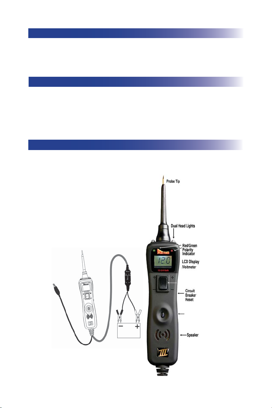
HOOK-UP
Unroll the Power Probe cable. Connect the RED battery hook-up clip to the POSITIVE terminal of the
vehicle’s battery. Connect the BLACK battery hook-up clip to the
battery. When the PP3 is fi rst connected to a battery (power source), it will sound a quick high and then
low beep and go into “Power Probe Mode (PPM) (See Mode #1 on page 10) and the 2 bright white LEDs
(dual head lights) will be on to illuminate the test area of the probe tip.
NEGATIVE terminal of the vehicle’s
QUICK SELF-TEST (PPM)
While the PP3 is in Power Probe Mode, press the power switch forward to activate the tip with a positive
(+) voltage. The positive sign (+) LED should light red and the LCD display will read the battery (supply)
voltage. If the tone feature is turned on, a high pitched tone will sound. Press the power switch rearward
to activate the tip with a
display will read “0.0” (ground). If the tone feature is turned on, a low pitched tone will sound. The Power
Probe is now ready to use. If the indicator did not light, depress the reset button of the circuit breaker on
the right side of the housing and try the self test again.
negative (-) voltage. The negative sign (-) LED should light green and the LCD
TURNING THE AUDIO TONE ON/OFF (PPM)
While the PP3 is in Power Probe Mode, just do a quick press of the mode button to toggle the tone on or off.
While quickly pressing (a quick press and release) the mode button, if a short high beep is heard, this means
the audio tone is turned on. If a short low beep is heard, the audio tone is turned off.
Power Switch
Mode
Button
/
3
Page 5
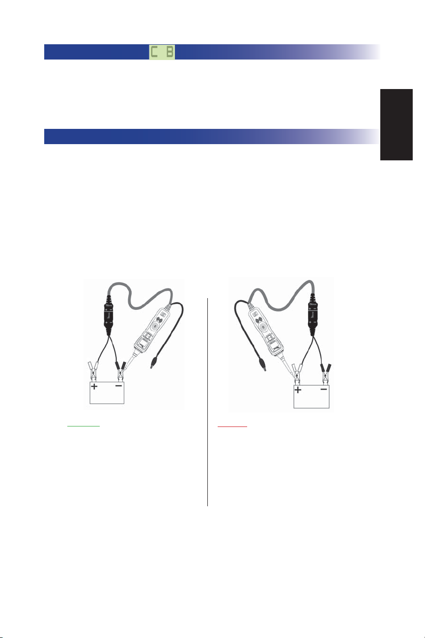
CIRCUIT BREAKER
In Power Probe Mode (Mode #1) with a the circuit breaker tripped, the LCD will display the symbol “C B”.
(see page 11-12 for detail) All other functions of the PP3 are still active. This means that you can still probe a
circuit and observe the voltage reading. When the circuit breaker is tripped, the PP3 will NOT be able to conduct battery current to the tip even when the power switch is pressed. Intentionally tripping the breaker and using the PP3 to probe can be considered an added precaution against accidental pressing of the power switch.
VOLTAGE & POLARITY TESTING (PPM)
While the PP3 is in Power Probe Mode, contact the probe tip to a POSITIVE circuit. The red positive sign “+”
LED will light and the voltmeter displays the voltage with a resolution of 1/10th of a volt (0.1v).
If the audio feature is turned on, a high pitched tone will sound. (See RED/GREEN POLARITY INDICATOR
& AUDIO TONE on page 10)
While the PP3 is in Power Probe Mode, contact the probe tip to a NEGATIVE circuit. The green negative
sign “–” LED will light and the voltmeter displays the voltage. If the audio feature is turned on, a low pitched
tone will sound.
Contacting the Power Probe tip to an OPEN circuit will be indicated by neither of the LED indicators lighting.
English
.0
0
While the PP3 is in Power Probe Mode. Contact the probe
tip to a
NEGATIVE circuit. The green negative sign “-
” LED will light. If the audio feature is turned on, a low
pitched tone will sound.
12.0
While the PP3 is in Power Probe Mode, contact the probe tip to
a
POSITIVE circuit. The red positive sign “+” LED will light
and the voltage reading of the circuit will be indicated on the
LCD display. If the audio feature is turned on, a high pitched
tone will sound.
4
Page 6

CONTINUITY TESTING (PPM)
While the PP3 is in Power Probe Mode, and by using the Power Probe tip in connection with chassis
ground or the auxiliary ground lead, continuity can be tested on wires and components attached or
disconnected from the vehicle’s electrical system.
The PP3 indicates continuity using 2 resistance levels. When the Power Probe tip has a resistance to
ground less than 20K Ohms but greater than 2K Ohms the LCD will indicate “0.0” volts but no
“-” LED. But when the resistance to ground less than 2K Ohms the LCD will indicate “0.0” volts and
also the
Green “-” LED. The higher resistance continuity function is useful for checking Spark Plug
Wires, (disconnected from ignition) Solenoids and magnetic pickup coils, and the lower resistance
continuity for testing relay coils and wiring. However the best way to prove continuity of connections to either Ground or Battery is to power up the connection using the Power Switch. If the Circuit
Breaker trips you know that you have a good solid low resistance connection.
Green
No Continuity
Continuity (less than 20 k Ω
but greater than 2k Ω)
0.0
Continuity (less than 2 k Ω)
Green
0.0
5
Page 7

ACTIVATING COMPONENTS IN YOUR HAND (PPM)
While the PP3 is in Power Probe Mode and by using the Power Probe tip in connection with the auxiliary ground lead, components can be activated right in your hand, thereby testing their function.
Connect the negative auxiliary clip to the negative terminal or ground side of the component being
tested. Contact the probe to the positive terminal of the component, the
indicator should light
GREEN indicating continuity through the component.
While keeping an eye on the green LED negative sign, quickly depress and release the power switch
forward (+). If the green negative sign “-“ LED went out and the red positive sign “+” came on, you
may proceed with further activation. If the
green negative sign “-“ LED went off at that instant or
if the circuit breaker tripped, the Power Probe has been overloaded. This could happen for the following reasons:
• The contact you are probing is a direct ground or negative voltage.
• The component you are testing is short-circuited.
• The component is a very high current component (i.e., starter motor).
If the circuit breaker is tripped, reset it by waiting for it to cool down (15 sec.) and then depressing the
reset button.
Connect the
negative auxiliary
clip
Contact the tip
to the positive
terminal of the bulb
green negative sign “-“ LED
English
Activate fuel pumps, magnetic
clutches, starter solenoids,
cooling fans, blower motors,
lights etc.
Press the power switch
forward to activate the
bulb
6
Page 8

TESTING TRAILER LIGHTS AND CONNECTIONS (PPM)
1. Connect the PP3 to a good battery.
2. Clip the auxiliary ground clip to the trailer ground.
3. Probe the contacts at the jack and then apply voltage to them. This lets you check the function and orientation of the connector and trailer lights. If the circuit breaker tripped, that contact is likely a ground. Reset the circuit breaker by letting it cool down (15 sec.) and depressing the reset button until in clicks into place.
7
Page 9

ACTIVATING COMPONENTS IN THE VEHICLE (PPM)
To activate components with positive (+) voltage: Contact the probe tip to the positive terminal of
the component, the
observing the
indicator
went out and the red positive sign (+) LED came on, you may proceed with further activation. If the
has been overloaded. This could happen for the following reasons:
• The contact is a direct ground.
• The component is short-circuited.
• The component is a high current component (i.e., starter motor).
If the circuit breaker tripped, reset it by allowing it to cool down (15 sec.) and then depress the reset
button.
Warning: Haphazardly applying voltage to certain circuits can cause damage to a vehicle’s electronic
components. Therefore, it is strongly advised to use the vehicle manufacturer’s schematic and diagnosing procedure while testing.
green negative sign “-” LED should light. Indicating continuity to ground. While
green indicator, quickly depress and release the power switch forward (+). If the green
green indicator went off at that instant or if the circuit breaker tripped, the Power Probe
TRICK: When poweringup components, you can
increase the life of your
Power Probe switch if
you fi rst press the switch,
then contact the tip to the
component. The arcing
will take place at the tip
instead of the contacts of
the switch.
English
8
Page 10

ACTIVATING ELECTRICAL COMPONENTS W/GROUND (PPM)
Contact the probe tip to the negative terminal of the component, the LED indicator should light RED.
While observing red positive sign “+” LED, quickly depress and release the power switch rearward
(-). If the red indicator went out and the
activation. If the green indicator went off at that instant or if the circuit breaker tripped, the Power
Probe has been overloaded. This could have happened for the following reasons:
• The contact is a direct positive voltage.
• The component is short-circuited.
• The component is a very high current component (i.e., starter motor).
If the circuit breaker tripped, reset it by allowing it to cool down (15 sec.) and then depress the reset button.
WARNING: With this function, if you are contacting a protected circuit, a vehicle’s fuse can be blown
or tripped if you apply ground to it.
green negative sign (-) came on you may proceed with further
Horn
Depress the rocker
switch rearward
to ground the horn.
9 9
Page 11

CHECKING FOR BAD GROUND CONTACTS (PPM)
Probe the suspected ground wire or contact with the probe tip.
Observe the green negative sign “-” LED. Depress the power switch forward then release.
If the green negative sign “-” LED went out and the red positive sign “+” came on, this is not a true ground.
If the circuit breaker tripped, this circuit is more than likely a good ground. Keep in mind that high current
components such as starter motors will also trip the circuit breaker.
OLLOWING & LOCATING SHORT CIRCUITS (PPM)
F
In most cases a short circuit will appear by a fuse or a fusible link blowing or an electrical protection device
tripping (i.e., a circuit breaker). This is the best place to begin the search.
Remove the blown fuse from the fuse box. Use the Power Probe tip to activate and energize each of the
fuse contacts. The contact which trips the PP3 circuit breaker is the shorted circuit. Take note of this wire’s
identifi cation code or color. Follow the wire as far as you can along the wiring harness, for instance if you
are following a short in the brake light circuit you may know that the wire must pass though the wiring
harness at the door sill. Locate the color-coded wire in the harness and expose it. Probe through the insulation with the Power Probe tip and depress the power switch forward to activate and energize the wire.
If the Power Probe circuit breaker tripped you have verifi ed the shorted wire. Cut the wire and energize
each end with the Power Probe tip. The wire end which trips the Power Probe circuit breaker again is the
shorted circuit and will lead you to the shorted area. Follow the wire in the shorted direction and repeat
this process until the short is located. ECT200 uses a wireless non-contact technique that guides you to the
short/open location.
RED/GREEN POLARITY INDICATOR & AUDIO TONE
The “RED/GREEN Polarity Indicator” lights-up when the probe tip voltage matches the battery voltage
within ± 0.5 volts. This means that if you contact a circuit that is not a good ground or a good hot, you will
see this instantly by the “RED/GREEN Polarity Indicator” NOT lighting. The Audio Tone runs parallel to
the “RED/GREEN Polarity Indicator and will also NOT react when contacting a circuit that does not match
the battery voltage thin ± 0.5 volts.
English
10
Page 12

MODES
The Power Probe III has been designed to work the same as the previous Power Probe circuit testers. Using the advanced features and modes is optional. However, understanding them will expand your diagnosing capabilities. The
LCD display indicates voltage levels of the circuit along with an identifying symbol showing you what mode it is in. The
additional features contain 5 new modes which give you specific information about how the circuit is reacting.
The 5 Modes can be accessed by depressing the Mode button and cycling through each one.
Mode #1 Power Probe Mode: While the PP3 is in “Power Probe Mode” and the probe tip is floating (not contacting a
circuit), the LCD backlight is on but the display is blank. If the audio tone is turned on you will see a speaker symbol in
the lower right corner of the display. Once you contact the probe tip to a circuit the LCD display will indicate the average
voltage level of the circuit. The red/green polarity indicator (See section Red/Green Polarity Indicator and Audio Tone) will
respond also, showing weather the circuit is positive or negative.
A secondary feature in this mode is the peak to peak threshold detection and signal monitoring. When contacting a signal
generating circuit such as a speaker wire with audio signals on it, the PP3 detects the peak to peak signals and displays
the peak to peak voltage on the display, the sound of the signals will be monitored and heard through the PP3 speaker.
The peak to peak threshold levels are pre-selected by the operator in “Mode 5”. See Mode #5 for more information on setting threshold levels. Placing the PP3 probe tip next to a sparkplug wire (NOT probing it directly), allows you to monitor the
sound of the ignition pulses at the same time display a peak to peak reading The PP3 senses the pulses in ignition wires
through capacitive coupling
By monitoring each plug wire in this way you can locate missing cylinders.
Mode #2 Negative Peak Mode: The Negative Peak Mode monitors a positive circuit and captures the lowest voltage
that it has dropped to. To do this: Place the PP3 in “Negative Peak Mode” by pressing and holding the mode button for 1
second until you hear a low pitched beep and the LCD display indicates a negative (minus) sign in the lower left corner.
The display should also indicate a reading of “0.0” with the probe floating. (This is because no voltage is present). Probe
the positive circuit you want to test and tap the mode button once. The LCD display will show the lowest detected voltage
of the circuit. If the circuit drops in voltage at anytime, a new lowest reading will be captured and displayed. You can then
do a quick tap of the mode button once again to reset the LCD display and indicate the new voltage level on the circuit.
Reset the LCD display by doing a quick tap of the mode button as often as necessary.
(DO NOT CONTACT PROBE TIP DIRECTLY TO THE SECONDARY IGNITION CIRCUIT).
An APPLICATION for the use of the “Negative Peak Mode”: Lets say you have a circuit that is suspect of loosing a connection and the voltage drops, causing something to turn off or malfunction. Probing the circuit and monitoring it in “Negative
Peak Mode” will instantly indicate as the circuit drops in voltage. You can monitor the circuit while wiggling wires and
pulling on connectors to see if the voltage drops. Since the minimum voltage reading is captured and held on the display,
you can inspect it at a later time. You could also perform a battery crank test.
Mode #3 Positive Peak Mode: The “Positive Peak Mode”, monitors the probed circuit and captures the highest detected
voltage. Place the PP3 into “Positive Peak Mode” by pressing and holding the mode button for 1 second until you hear
a beep. Repeat this until you hear a quick high pitched beep and the LCD display indicates a positive (plus) sign in the
lower left corner. The display should also indicate a reading of “0.0” with the probe tip floating. Probe the circuit and the
PP3 instantly displays and holds the highest voltage reading. This means you can remove the probe away from the circuit
and the voltage reading remains displayed for your reference. Reset the LCD display by doing a quick tap of the mode
button.
An APPLICATION for the use of the “Positive Peak Mode”: Let’s say you have a circuit that is supposed to be off and is
suspected of turning on inappropriately or getting a signal for some reason. Probing the circuit and monitoring it in the
“positive peak mode” will instantly indicate as the circuit increases in voltage. You can monitor the circuit while wiggling
wires and pulling on connectors to see if the voltage increases. Since the maximum voltage reading is captured and held
on the display, you can inspect the reading at a later time.
Maybe you have to probe a circuit deep under a dash and the display is obstructed from view. In “Positive Peak Mode” just
probe the wire then remove the probe and look at your voltage reading. Connect to starter terminal to capture maximum
voltage to the starter while cranking. Quickly finds voltage drops in the wiring & start connection (Solenoid).
/
11
Page 13

Mode #4 Peak to Peak Mode: The Peak to Peak Mode measures the difference between the positive and negative peak
voltage levels over a 1 second period. With this feature you can measure and monitor for example, the diode rectifier in
a charging system while the engine is running. The peak to peak readings will give the technician the data necessary to
determine if a diode rectifier is defective or not. A normal peak to peak reading while testing a charging circuit is usually
under a volt. If a defective rectifier is present the peak to peak reading will be over 1 volt and possibly over 3 volts.
When probing in “Peak to Peak Mode” the display shows activity of circuits such as fuel injectors, distributor pick-ups,
cam and crank sensors, oxygen sensors, wheel speed sensors, hall effect sensors. Measures fly back voltage of injectors
to quickly find a problem.
Mode #5 Threshold Level Setting for the Peak to Peak Detection in Power Probe Mode” (Mode #1) This mode is
only used to adjust the threshold voltage in “Power Probe Mode” for Peak to Peak Detection and Signal Monitoring.
To set the threshold level for the peak to peak detection in “Power Probe Mode”, press and hold the mode button for one
second until you hear a beep. Repeat this a second, third and forth time and/or until an alternating positive (+) and negative (–) sign is present in the bottom left corner of the LCD display. You can now toggle the threshold level by a quick tap of
the mode button and observing the voltage level settings. The peak to peak threshold voltage settings loop incrementally
from 0.2, to 0.5, to 1.0, to 2.0, to 5.0, to 10.0, to 50.0 and return back to 0.2 again. AN audio installer would find the 0.2v
setting convenient. Once you select the desired threshold voltage, press and hold the mode button again until it beeps.
This returns you to the “Power Probe Mode” (Mode #1). You will know that you are in the “Power Probe Mode” when the
LCD display is blank and/or with the “Speaker Symbol” shown in the bottom right corner.
Navigation Mode# Display Mode/Function Output
English
When the Power Probe III
is initially connected to the
vehicles battery or a 12-24
volt power supply, it enters
Mode #1 automatically.
To enter into Mode #2
press & hold Mode button
until you hear a low pitched
beep.
To enter into Mode #3 press
& hold Mode button until you
hear a high pitched beep.
To enter into Mode #4 press
& hold Mode button until you
hear a low to high pitched
beep.
To enter into Mode #5 press
& hold Mode button until you
hear a mid pitched beep.
To return to Mode #1 press &
hold Mode button, until you
hear the high & low beep.
#1
#2
#3
#4
#5
Actively alternating +
to - to + , etc.
12
Power probe Mode:
with Audio Tone On
Power probe Mode:
with Audio Tone Off
Power probe Mode:
with the Circuit Breaker
tripped with Audio
Tone Off
Power probe Mode:
with the Circuit Breaker
tripped with Audio
Tone On
Negative Peak to
Peak Mode
Positive Peak to
Peak Mode
Peak to Peak Mode
Peak to Peak Thresh-
old Setting Mode:
Detects Peak to Peak
in Power Probe Mode.
Displays the average
D.C. voltage.
Displays the Peak
to Peak A.C. voltage
when the voltage is
greater than Mode 5
Threshold setting.
Limited to 65v
Captures the most
Negative voltage
transition.
Captures the most
Positive voltage
transition
.
Displays the difference between Peak to
Peak voltage.
Sets the Peak to Peak
Threshold Level for
the Mode #1 display
to transition from D.C.
to A.C.
Page 14

Power Probe 3 Specifi cations
DC 0 – 70V + 1 digit
P-P 0 – 70V
Frequency response of tone pass through
10Hz to greater than 10 Khz
PP display
15Hz Square Wave
35Hz Sine Wave
Power Probe Mode – Continuity to ground
First level – display is enabled less than 20K
Second level – green LED is enabled less than 2K
– & + Peak Detector Response
Single event capture less than 200µs pulse width
Repetitive events less than 1µs pulse width
Peak to Peak Mode
0 – 70V + 1 digit
4Hz to over 500kHz Square Wave input
4Hz to over 250kHz Sine Wave input
Threshold for PPAC/Audible passthrough
Circuit Breaker
8 amp thermal response – Manual reset
Typical Response
8 amps 10 amps 15 amps 25 amps Short Circuit
No trip 20 min. 6 sec. 2 sec. 0.3 sec.
Short
Circuit
25 amps
15 amps
10 amps
8amps
.1 0.3 2 sec. 6 sec. 20 min.
13
Page 15

ROCKER SWITCH REPLACEMENT
English
 Loading...