

Page 1

Diagnose Electrical
Circuits Like a Pro!
English - Español - Français - Deutsch - Italiano
Page 2

Contents
Congratulations ....................................................................................................... 4
Parts......................................................................................................................... 5
The SMART transmitter ...................................................................................... 6
Charcteristics of the Short/Grounded Circuit signal ............................................... 8
Charcteristics of the Open Circuit signal ......................................................... 9&10
The SMART receiver .......................................................................................... 11
Battery Installation ................................................................................................ 12
Testing the Smart Receiver ................................................................................... 12
Pulse Mode............................................................................................................ 12
Locking the Sensitivity of Short//Grounded Circuit signal ..................................14
Locking the Sensitivity of Open Circuits .............................................................. 14
Direction to Short .................................................................................................. 15
How to Use the ECT-2000 in Diagnosing Circuits
2
............................................... 16
Page 3

Contents
How to Trace Out a Short Circuit to Chassis Ground ........................................... 17
Isolate your Circuit ............................................................................................... 18
Verify the Short Circuit to Ground ........................................................................ 18
Short Circuit inside a Wire Harness ...................................................................... 19
Reception Distance and What that Means ............................................................ 20
Tracing Circuits that are Shielded ................................................................................ 21
English
Open Circuit Signal vs
How to Trace an Open Circuit ..................................................................................... 23
Verify an Open Circuit ................................................................................................. 23
Bench Tracing a Wire Harness ..................................................................................... 24
Tracing out Battery Drain or Current Draw ................................................................. 25
Circuit Wiggle & Flex Test .......................................................................................... 26
Index ............................................................................................................................ 27
/Grounded Circuit
Signal ...................................................... 22
3
Page 4

Congrat
Congrat
ulations
Thank you for choosing the Power Probe “SMART ECT-2000” (Electronic Circuit Tracer- 2000)
This instruction booklet will give you some valuable diagnosing tips gathered from the fi eld and from our testing lab. This instruction booklet has
convenient references that will take you to appropriate pages that provide more information and clarifi cation. Taking the time to read this instruction booklet carefully will give you valuable insight to these detailed techniques in tracing automotive circuits.
We designed the ECT-2000 as a quick solution to your automotive circuit problems. The ECT 2000 consists of 2 main components. A SMART
transmitter and a SMART receiver along with a set of connection adapters that will help you:
• Locate short circuits without unnecessarily removing plastic panels, molding, and carpet.
• Trace wires to see where they lead
• Locate electrical components in the vehicle
• Find open circuits, switches or breaks in wires
• Trace and locate the cause of a severe battery drain
• Test and fi nd intermittent connections
• Check continuity with the assistance of the Power Probe III
These features are extremely handy for the professional technician that understands automotive electrical. An appropriate schematic or wiring
diagram is always useful and many times necessary when tracing circuits. The better you understand your circuit, the better the ECT-2000 can
assist you.
ulations
4
Page 5

English
#PNECT000R
SMART receiver
#AA6
Back
Probe
#PN012SET
Battery Hook-up
Clip Set
#PPPP02 - Piercing Probe
#20014 - Universal Wire Adapter*
#AA4
Blade
Probe
#AA3
Light Bulb Adapters
#PNECT057
Alligator Clip Adapter
#AA1
#AA2
#PNECT000T
SMART transmitter
Parts
Included in the Kit:
SMART transmitter
SMART receiver
1-Blade Probe**
1-Back Probe**
3-Light Bulb Adapters**
1-Piercing Probe
1-Alligator Clip Adapter
1- Battery Hook-up Clip Set
1-Universal Wire Adapter*:
(You can solder to any connection
for custom use.)
*Extra universal wire adapters can be
purchased. (Sold in packs of 5, Part
#PNECT050)
All banana jacks/plugs are standard
4mm making other test leads or
Adapters usable with this product.
**See pg. 16 for application
5
Page 6

The
SMART
The SMART transmitter is designed to generate Grounded Circuit signals and Open Circuit signals. The grounded and the open circuit signals are
very different from each other, so it is very important to understand the differences in each signal type. (see “Characteristics of the Short/Grounded Circuit Signal” pg.. 8 and Characteristics of the Open Circuit Signal” pg..9)
to detect intermittent problems. (See “Circuit Wiggle and Flex Test” pg.. 26)
Self-Test
The area located on the face of the SMART transmitter, with the words “Place receiver pick-up in this area to self-test” is used for testing the
SMART receiver.
transmitter
Power Lead
The 20 ft. power lead of the SMART transmitter supplies power by connecting directly to the vehicles
battery and the long length provides easy access to circuits throughout the vehicle. The RED clip
connects to the positive side of the battery and the BLACK clip connects to the negative. It can be
connected to a power source from 12 to 42 volts.
Signal Lead
The signal lead with green banana jack, plugs into the assortment of adapters, probes, and clips that
are provided for you in the ECT-2000 kit. These accessories simplify connecting to your circuit.
Tone On/Off - Toggle Tone
“Tone On/Off” button toggles the tone of the SMART transmitter’s speaker on or off.
The toggle tone feature of the SMART transmitter gives you the ability to detect changes in the circuit
6
Page 7

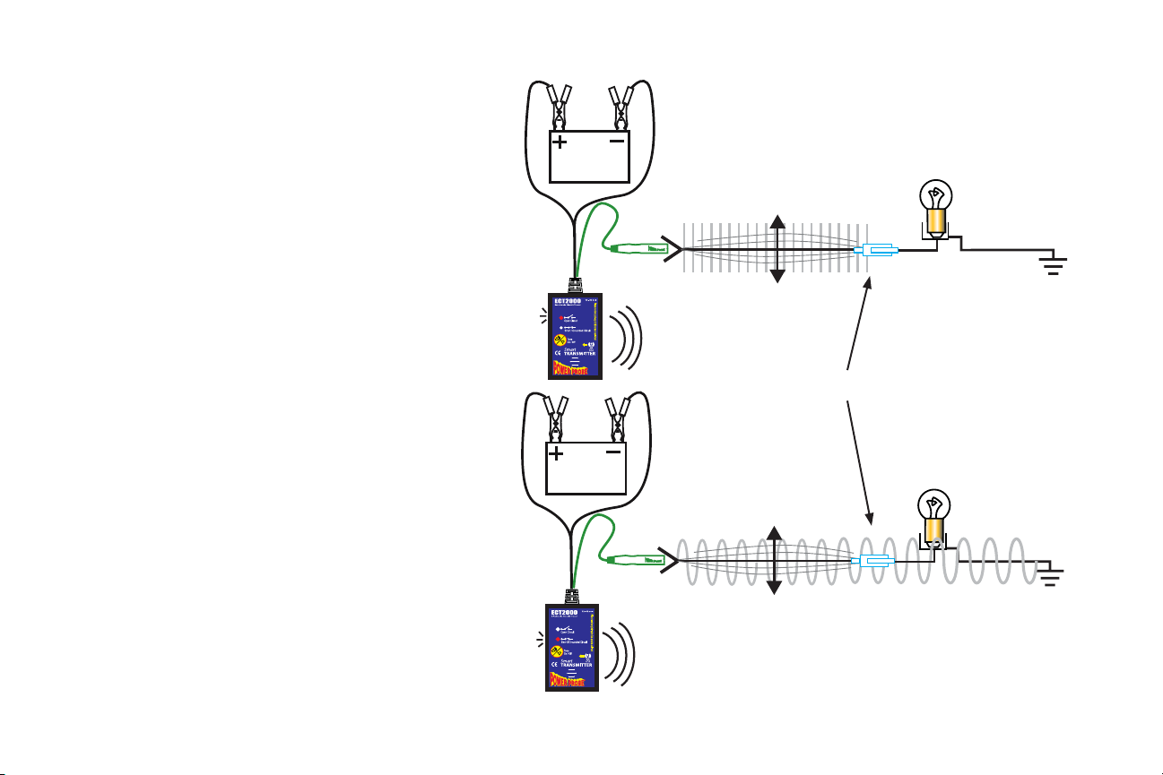
After connecting the SMART transmitter’s 20 ft. power lead to the vehicle’s battery, a signal is generated through the green signal wire and banana plug. This is connected to the circuit you want to trace. The signal will radiate along the circuit, which you can detect by using the SMART
receiver. There are two types of circuit signals that the SMART transmitter generates. They are the Grounded Circuit SIGNAL and the OPEN
CIRCUIT SIGNAL.
It is very important to familiarize yourself with both of these signals and how they work in your circuit. The “Grounded Circuit signal” and the
“open circuit signal” are different from each other, which you should understand. (See: “Characteristics of the Short/Grounded Circuit Signal”
pg.. 8 and “Characteristics of the Open Circuit Signal” pg. 9&10)
The 2 main features of the ECT2000 is that it transmits a signal into a circuit with the SMART transmitter and then you trace it with the
SMART receiver . The easiest way to insure that you are following the problem circuit is to isolate it from other parallel circuits.
English
Complete Circuit Signal
Open Circuit Signal
7
Page 8

Path of least resistance
Characteristics of the Short/Grounded Circuit Signal:
1. Strongest when fl owing exclusively through one wire
When the signal is conducting through only one wire, the signal
strength is at its maximum because 100% of the signal is traveling through that wire exclusively to return back to the negative
side of the battery. If the signal branches out to parallel circuits,
its strength divides and of course is weaker in each branch of the
divided circuit. But when the signal recollects through the single
negative cable to return to the battery, the signal strength is at
its maximum again because 100% of the signal is concentrated
through the single negative battery cable. (see “Isolate the Circuit
You are Tracing” pg. 18)
2. Travels the path of least resistance
In case of a short circuit that blows its fuse reliably, you can sometimes get away with not having to isolate the circuit. The majority
of the signal will follow the path of least resistance through the
short and then back to the battery. In fi g.1, you can see the majority of the signal travels right to the short circuit. You can also see
only a small portion of the signal running through parallel wires.
3. A 4 KHz Polarized Signal
The fact that the Grounded Circuit signal is a 4 KHz polarized signal provides directional information for the SMART receiver to pick up. This
capability to indicate the direction to the short or ground takes the guesswork out of tracing grounded circuits. (See “Direction to the Short” pg. 15)
4. Carries a current of only 100 mA.
When generating a short/Grounded Circuit signal, a maximum of 100 milliamp fl ows from the signal lead. This keeps you safe from damaging
sensitive computer circuits.
Major portion of signal
goes into short (ground)
Lights have resistance
and limit signal fl ow
Very small traces of
signal branch into
parallel circuits
Fig. 1
8
Page 9

Characteristics of the Open Circuit Signal are:
1. Transmits through NON Conductive Materials
The signal that the ECT transmits when tracing open
circuits, radiates what is called an E-fi eld. For the sake of
simplicity we will refer to an E-fi eld in this manual as an
“Open Circuit Signal”.
The open circuit signal radiates from wires and passes
through non conductive material such as dry carpet, plastic
panels or plastic molding. The SMART receiver is used to
detect these signals so you can trace and locate the open or
break in the circuit.
(See “Locking the Sensitivity” pg. 14)
2. Easily Shielded by Conductive Materials
The open circuit signal is however easily shielded by
conductive materials such as metal, wet carpet, neighboring
wires in a harness and even your hand. This means that if
conductive materials are between the transmitting wire and
the SMART receiver, the open circuit signal will not penetrate through and therefore not be detected by the receiver.
So it is necessary to be aware of possible shielding issues
and try to avoid them as much as possible.
A great alternative to the SMART receiver in detecting open
circuit signals is to use the Power Probe III by direct contact.
(see “Verify an Open Circuit” pg. 23)
Dry Carpet / Plastic Panels & Molding
Wet Carpet / Metal/ Shielding Wire Harness
Open signal passes
through dry nonconductive material
Holding the receiver by this corner,
prevents your hand from sheilding the
open circuit signal.
English
(continued on next page)
9
Page 10

3. Capacitive Coupling to Parallel Floating Circuits
Another characteristic of the open circuit signal is that it will capacitive couple to parallel fl oating circuits. (See: “Bench Tracing a Wire Harness”
pg. 24)
4. Travels to ALL Open Ends
In Fig. 1 we are injecting an open circuit signal into a
parallel circuit that has three wires. Two of those wires lead to
open switches and the other leads to the open/break. As you can
see the open circuit signal travels to all open ends. This makes it
necessary to isolate the problem circuit away from the others.
Signals are all
over the place,
because the
problem circuit
has not been
isolated
Problem circuit not isolated
5. Can only be present in a circuit when there is a resistance
greater than 100 ohms
(See: Open Circuit Signal vs Grounded Circuit Signal” pg. 22)
Fig. 1
6. Has NO Polarity
The open circuit signal does not have a polarity therefore the ECT
receiver gives no direction indication as to break in the wire. You
will need to logically reason the direction of the break in the circuit
and then continue to trace it.
7. 8 volt amplitude and 4 kilo-Hertz signal
The 4 Kilo-Hertz signal of the open circuit signal can be detected by the SMART receiver. (See: “Locking the Sensitivity for Open Circuits” pg. 14)
You can also use the Power Probe III for open circuit signal detection by direct contact. (See: “Verify an Open Circuit” pg. 23)
10
Page 11

The
SMART
The SMART receiver is designed to detect the “Grounded Circuit signals” and the open circuit signals from the SMART transmitter.
Auto shut-off feature
The SMART receiver will automatically
shut-off within 30 seconds when it is NOT
receiving a signal.
The “Open & Short Pick-Up” located on the
side of the receiver housing labeled “Open and
Short Pick-up” is to sense and detect complete
and open circuit signals.
The “Power/Sensitivity Lock” button does a few things.
1. It turns the SMART receiver ON and enters “pulse
mode” (see “Pulse Mode” pg. 12)
2. It turns the SMART receiver OFF.
(providing it is not receiving a signal)
3. It locks the sensitivity of the reception into desired
strengths. (see “Locking the Sensitivity” pg. 14)
4. It UN-locks the sensitivity and returns the SMART
receiver back to “pulse mode”.
Receiver
The “Wire Harness Probe” is for
probing a harness to detect the open
circuit signal. (See “Tracing Circuits
that are Shielded” pg.21 )
The “Open Circuit” LED on
the other side of the housing
indicates when it is receiving
an open circuit signal.
The “Direction to Short/
Ground” indicators point you
in the direction to the short
or ground of the complete
circuit. (See “Direction to the
Short Circuit” pg. 15)
English
11
Page 12

Battery Installation
1. To install the batteries, remove the battery cover on the back of the housing and insert (2) AAA batteries into the
battery compartment. Be sure the polarity of the batteries are correct then replace the battery cover.
Testing the SMART Receiver
To test the SMART receiver, connect the SMART transmitter to the vehicle’s battery, turn on the SMART receiver by
pressing the “Power/Sensitivity Lock” button. Place the “Open & Short Pick-Up” of the receiver on top of the green
signal lead. The SMART receiver should detect the open circuit signal and indicate this by the open circuit LED indicator fl ashing and pulsing a beeping tone.
To test the SMART receiver for the “short/Grounded Circuit signal” connect the green signal lead to the negative post
of the battery. Then you can test the Grounded Circuit signal by
placing the ”Open & Short Pick-Up” of the receiver parallel to
the green signal lead. The SMART receiver should detect the
“Grounded Circuit signal” and the show the direction to ground
by the “Direction to Short or Ground” indicator.
Pulse Mode
When you fi rst turn on the SMART receiver it enters into “Pulse
Mode”. “Pulse Mode” is great for the initial detection of the
transmitting signal. You can also get a feel for the strength of
the transmitting signal.
As you place the “Open and Short Pick-Up” near an transmitting signal, an LED indicator will blink repeatedly along with
an audible beep.
The SMART receiver has 7 sensitivity levels. You can sense
each level by observing and listening to the slight increase in
pulse frequency as you slowly lower the receiver nearer to the
transmitting circuit. The closer you place the “Open and Short
Pick-Up” to the transmitting signal, the faster it will pulse.
Pulling the receiver away from the transmitting signal it will pulse slower.
No signal zone
(no pulse)
Weak signal zone
(slow pulse)
Strong signal zone
(rapid pulse)
12
Page 13

When the SMART receiver is in “pulse mode”:
1. It detects both “grounded” and “open” circuit signals.
2. It picks up and determines strong from weak signals by the pulse frequency rate.
3. The sensitivity is ready to be locked in, by pressing the “Power/Sensitivity Lock” button.
4. It detects and displays the direction to ground or a short circuit.
While in “pulse mode” and then pressing the “power/sensitivity lock” button, the SMART receiver’s sensitivity will now be locked and no longer
be in “Pulse Mode”. To return to “Pulse Mode” press the “power/sensitivity lock button again.
The SMART Receiver’s Reception Sensitivity:
When the SMART receiver is in “pulse mode” you can lower it progressively closer to the transmitting signal and hear the increase in the pulse
frequency as it passes each of the 7 sensitivity levels. The fastest pulse frequency is when you are nearest to the transmitting signal. Once you
press the “Power/Sensitivity Lock” button the reception sensitivity is locked into that distance (plus/minus a couple of inches) from the transmitting circuit.
In order to lock the reception sensitivity of the SMART receiver, two conditions must be met.
1. The SMART receiver must be in “Pulse Mode”.
2. The SMART receiver must be receiving a signal
When these two conditions are met, you can now press the “Power/Sensitivity Lock” button to lock the distance of the SMART receiver and
reception sensitivity.
When the SMART receiver’s reception sensitivity is LOCKED:
1. The reception sensitivity is held at the distance set.
2. It won’t pick signals farther than the level set.
3. It detects only the type of signal you locked into.
For instance if you are locked into an “open circuit signal”, it will not pick up “Grounded Circuit signals”. If you are locked into a “Grounded
Circuit signal” it will not pick up “open circuit signals”.
English
13
Page 14

Locking the Sensitivity for Short/Grounded Circuits
To lock the SMART receiver’s sensitivity for short/grounded circuits, it must be
turned on and in “pulse mode”. Hold the “Open & Short Pick-Up” of the receiver
parallel and as near to the wire as you can while achieving the most rapid pulse
rate. (See: Fig. A) Now press the “Power/Sensitivity button”. The SMART receiver
is now locked into the strong “Grounded Circuit signal” and will ignore weaker
parallel circuit signals. If you need to readjust the receiver’s sensitivity so that it
will pick up weaker circuit signals and be more sensitive, press the “Power/Sensitivity Lock” button to return to ““pulse mode”.” This time, hold the receiver a little
farther away from the wire so that the pulse rate is a little slower, and then repress
the “Power/Sensitivity Lock” button.
Locking the Sensitivity for Open Circuits
To adjust the SMART receiver so that it is at its most sensitive setting in open
circuit tracing. First turn on the SMART receiver. It is now in “pulse mode”. Hold
it as close to the open circuit as you can while receiving the most rapid pulse
frequency.
Now lift the SMART receiver about 6 inches away from the circuit and press the
“Power/Sensitivity Lock” button. (See: Fig. B) At this level you should be able to
pick up the open circuit signal in that circuit and eliminate other signals that could
be capacitive coupling into neighboring fl oating circuits and causing you problems.
If you need to adjust the SMART receiver so that the reception sensitivity is more
sensitive, press the “Power/Sensitivity Lock” button to return to “pulse mode”.
Now hold the SMART receiver about 8 inches from the transmitting circuit and
then press the “Power/Sensitivity Lock” button again. Repeat these steps until you
achieve the proper setting for your application.
Fig. A
Close distance for
Short/Complete
circuits.
Fig. B
6-10” from the wire
for Open circuits.
14
Page 15

Direction to the Short
The short/Grounded Circuit signal is polarized. This gives the SMART receiver the information it needs to show you the direction
to the short or the direction to ground.
When you place the SMART receiver’s
“Open & Short Pick-Up” parallel to the wire
of the Grounded Circuit signal, “Direction to
Short/Ground” indicator will point you in the
direction to ground. If you were to fl ip the
SMART receiver in the opposite direction it
will detect the polarity change, the “Direction
to Short/Ground” indicator will fl ip, and it
will still point you in the direction to ground.
Keep in mind that the receiver’s “Open &
Short Pick-Up” must be held parallel to the
circuit for the “Direction to Short/Ground” to
indicate.
The ECT 2000 works equally well with either
positive chassis ground or negative chassis
ground. The only thing you need to keep
in mind is, when tracing short circuits the
SMART receiver always points you towards
the minus of the battery so if you have a short between your wiring
and the chassis is a positive ground system, you just need to trace in
the opposite direction the LED is pointing!
Direction indicator shows
direction to ground or short.
Direction indicator shows
direction to ground or short.
English
No reception when
NOT held parallel
to circuit.
15
Page 16

How to Use the
Adapters
Adapters in Diagnosing Circuits
Connection Accessories
Included in the ECT-2000 are the following connection accessories.
• Alligator Clip: for connecting onto any conductor such as a wire or a terminal.
• Blade Probe: for tapping into fuse socket terminals and connectors.
• Back Probe: for back probing connectors.
• Piercing Probe: for tapping into wires by piercing through the insulation.
• Light Bulb Socket Adapters: 3 common types for connecting easily to light bulb socket
terminals. There are times when the short or open tail or brake light circuit is located
nearer to the bulb socket. It is here where you may fi nd it much easier to diagnose the
circuit by injecting a signal into the light socket directly.
• Universal Wire Adapter: for making your own custom connector.
Using
Blade
Probe
in fuse
terminal
Fig. 3
Alligator
Clip to
inject the
signal
Fig.1 There are times when a short or open circuit is located
closer to the tail light or brake light circuit. It is here where you
may fi nd it much easier to diagnose the circuit by injecting a
signal into the light socket directly. The bulb socket adapters
provide a quick and easy way to connect to bulb socket termi-
Fig. 1
Fig. 2
nals.
Fig.2 Other times it maybe necessary to inject the signal at the
fuse panel using the fl at blade adapter.
#AA6
Back
Probe
#PPPP02 - Piercing Probe
#20014 - Universal Wire Adapter*
#AA4
Blade
Probe
#AA3
Light Bulb Adapters
#PNECT057
Alligator Clip Adapter
#AA1
#AA2
16
Using Bulb adapter
to inject the signal
Fig.3 Using the alligator clip adapter on an already exposed
wire or the piecing probe are other options.
Page 17

How to Trace Out a Short Circuit to Chassis Ground
A direct short to chassis ground that blows a fuse, is one of the simplest circuits to trace for one simple reason. The majority of the “Grounded
Circuit Signal” travels THROUGH THE SHORT CIRCUIT TO CHASSIS GROUND making it easy to trace. This sometimes eliminates the need
for isolating the circuit.
1. Remove the blown fuse
2. Connect the SMART transmitter’s “power lead” to the vehicles battery
3. Connect the “signal lead” to the shorted terminal of the fuse panel using the Blade probe.
4. Turn on the SMART receiver. It will be in “pulse mode”.
5. Place the “Open & Short Pick-Up” about 2” from the wire harness and parallel to the shorted wire until the “Direction to Short or Ground”
indicator beeps rapidly.
6. Press the “Power/Sensitivity Lock” button.
7. Trace the circuit in the direction of the indicator until you loose the signal.
8. If you reach an obstacle remove it or work through it. Remember to ISOLATE THE CIRCUIT YOU ARE TRACING. Inspect the circuit
and verify the short. (See: “Verify a short circuit to ground” pg. 18)
9. Isolate the short circuit you are tracing and reconnect the “signal lead directly to the new found part of the shorted wire. (See: “Isolate the
Circuit you are Tracing” pg. 18)
10. Continue to follow the signal until you loose it.
11. Inspect the circuit and verify the short.
12. Repeat steps 7 through 10 until you fi nd the cause of the short circuit.
13. Once you fi x the short, reconnect all the sections of the circuit you had disconnected earlier.
English
17
Page 18

Isolate the Circuit You are Tracing
Isolating the circuit you want to trace is absolutely necessary when
using “Open Circuit Signals”. It is always good to disconnect the
circuit you are tracing away from other parallel circuits. Once you
isolate the troubled circuit, you can then connect the SMART transmitter’s signal lead exclusively to your selected circuit. Connecting
exclusively to your ISOLATED circuit insures that the SIGNAL is
confi ned in just that one single circuit. The signal strength remains
constant throughout the isolated circuit. This makes the circuit
easier to trace. You also eliminate confusion of the signal branching
off to other areas that will lead you astray. When you are fi nished
diagnosing, don’t forget to reconnect the isolated circuit.
Isolating a short/grounded circuit is best done by removing the
loads in the circuit. This accomplishes two things: 1. It assures
that 100% of the signal is being transmitted down the wire you are
tracing, 2. if the circuit goes intermittent, the transmitter will alert
you. (See: “Circuit Wiggle & Flex Test” pg. 26)
Verify a Short Circuit to Ground
One of the best tools for verifying a short circuit to ground is the
Power Probe 1, 2, or 3. To verify a short circuit connect the Power
Probe to the circuit and press the power switch forward. If the Power
Probe’s circuit breaker trips, you have verifi ed the short.
Be careful not to power up circuits that are connected to the vehicles onboard
computer. You may have to unplug the computer or electronic modules when
performing short circuit verifi cation on electronic systems.
place, because
circuit has not
Fig. 1
Fig. 2
Signals are
all over the
the problem
been isolated
Signal injected directly
into the problem circuit.
Problem circuit not isolated
Disconnected
from circuit
These circuits are no longer
a problem because they are
disconnected from the
problem circuit.
18
Page 19

Short Circuit Inside a Wire Harness
A common occurrence inside of wiring harnesses is that there are two wires running close and parallel to each other. One wire is the positive wire
that fl ows one way and the ground wire that fl ows back the opposite direction. When the signal source runs closely parallel to the signal return, as
in this case, they cancel each other and the signal strength is considerably reduced.
You can pull one wire at a time away from the other wires, creating some distance between them. As you hold the wire away from the other wires,
the signal canceling effect is removed in that area and the signal strength will increase in the wire. You can now get a reading off of the wire with
the SMART receiver by holding it parallel to the receiver’s pick-up area. Take note of the directional indicator of the SMART receiver. Check for
the other wire that indicates the opposite direction. You can now assume that both wires are in the same circuit. Trace both wires as a pair along the
harness until you fi nd the problem. (see illustration)
+ supply signal
– return signal
__________________
= 0 reception
English
When supply and return signals run close and
parallel to each other, they can practically
cancel each other out to the point where there
will be no signal detection.
Short circuit
inside wire
harness
19
Page 20

Reception Distance and What that Means.
When tracing parallel circuits, you can determine if a one wire has a stronger “Grounded
Circuit signal” present over another wire. The wire that has a stronger signal carries a larger
current. This means the circuit that has the stronger signal also has a lower resistance compared to the other parallel branch. Just knowing this information can come in handy when
determining the fault of a circuit.
Once the SMART receiver is locked into the short/Grounded Circuit signal, (see “Locking the sensitivity of short/grounded circuits”) note the distance of the pick-up area to the
wire as you slowly lower it down near to the wire. For example you will notice the SMART
receiver’s indicator comes on about 2 inches with one
wire and 3 inches with the other wire. The wire that
makes the receiver come on 3 inches away is transmitting a stronger signal than the circuit that makes the
receiver come on only 2 inches away.
That’s important to know so you can understand and
determine which wire has a stronger signal.
This is why it is always recommended to isolate your
troubled circuit. Isolating your circuit insures that you
are following the correct circuit and it avoids confusion with other parallel wires or circuits.
(See “Isolating the Circuit”pg. 18)
20
Page 21

Other wires can shield
open circuit signals.
Wet carpet, metal and
even your own hand can
shield open circuit signals.
Plastic Harness Cover
Wire harness probe lets
you probe between wires
Tracing Circuits that are Shielded.
Quite often you will need to trace circuits in areas that are shielded from the
SMART receiver. This doesn’t have to be an impossible feat. Sometimes just a
little logic and planning can overcome many obstacles. If your circuit enters a
shielded area, consider if it may have an exit point as well. If you receive a signal
going into a shielded area and a signal going out, you can consider the problem
not in the shielded area. Since you found the exit point of the circuit exposing
the wire is unnecessary. If you fi nd that the signal does not exit the shielded area,
then you might need to remove the shield and probe further. (See: “Verify an
Open Circuit” pg. 23)
English
Break/Open
21
Page 22

Open Circuit Signal vs
Grounded Circuit Signal
Open circuit signals can only be present in a circuit
when there is a resistance of about 100 ohms or greater.
(Figure A)
If a switch was to close in this circuit, (Figure B) the
open circuit signals would cease to emit and the short/
Grounded Circuit signal would replace it. The SMART
transmitter will also sound a tone that tells you that the
circuit has just made contact with ground. (Tip: Wiggling and pulling wires that have an open circuit signal
on them can lead you to the problem. This is done by
the SMART transmitter alerting you if the circuit you
are pulling on makes contact to a grounded circuit.)
(See: “Circuit Wiggle & Flex Test” pg. 26)
The point here is that Short/Grounded Circuit signals
take priority over open circuit signals. So be sure your
open circuit that you are tracing does not have any kind
of continuity to ground present.
22
Page 23

How to Trace out an Open Circuit:
An open circuit does not complete a path to ground. The cause for an open circuit can vary from an open switch, unplugged connector, bad connections and breaks in wires.
1. Connect the SMART transmitter’s power lead to the vehicle’s battery.
2. Connect the SMART transmitter’s signal lead to the open circuit.
3. Turn on the SMART receiver. It will be in “pulse mode”.
4. Place the “Open & Short Pick-Up” near and parallel to the open wire until the “Open Circuit” LED indicator blinks and beeps. (be careful to
hold the SMART receiver from the outer edge to prevent your hand from shielding the signal)
5. Lift the SMART receiver away from the open circuit so that the pulse of the “Open Circuit” indicator slows down but doesn’t stop completely.
6. Press the “Power/Sensitivity Lock” button.
7. Hold the SMART receiver near to the open circuit and while the “Open Circuit” indicator is ON steady, follow the path of the circuit or wire
until you loose the signal.
8. If you reach an obstacle, remove it or work through it. Remember to ISOLATE THE CIRCUIT YOU ARE TRACING. Inspect the circuit and
verify the open circuit. (See” “Verify an Open Circuit” below.)
9. Continue Steps 7-8 until you fi nd the open or break in the circuit.
Verify an Open Circuit:
One of the best methods for verifying an open circuit is using the Power Probe III circuit
tester together with the SMART transmitter. Since the SMART transmitter’s open circuit
signal delivers 8 volts and a 4 kHz signal, it can be easily detected by directly contacting
the Power Probe III to the wire of the transmitting circuit.
Contact the probe of the Power Probe III to the open circuit with the open circuit signal
applied to it. You should hear the 4 kHz tone from the Power Probe III speaker. If you
don’t hear the 4 kHz tone, inspect the circuit closer to determine why? If you hear the 4
kHz tone, you are on the correct circuit.Testing the open circuit with SMART transmitter together with the PP3 has advantages over just a continuity test. This is because the
SMART transmitter’s toggle tone feature will alert you if the open circuit makes contact
with an intermittent grounded circuit. (See: “Circuit Wiggle & Flex Test” pg. 26)
23
English
Page 24

Bench Tracing a Wire Harness
There are cases where you may have a wire
harness removed from the vehicle, sitting on
the bench, and tracing an open circuit. Wire
harnesses that are removed from the vehicle’s
electrical system have only fl oating wires in
them. The open connectors of the harness are
connected neither to positive nor negative
therefore all of the harness’s circuits are open
and fl oating. It is important to be aware that
the open circuit signal will capacitive couple
into fl oating circuits that run parallel and next
to the transmitting signal wire. (See Figure A).
Floating circuits that couple the open circuit
signal also transmit the signal too and will
even couple back to the wire you want to
trace. This prevents the SMART receiver from
locating the break in the wire because all the
wires are transmitting signals. You can be easily led down the wrong circuit if you are not
aware of this.
To correct this problem, you need to tie all
parallel fl oating open circuits to either ground
or a positive voltage (see Figure B).
All neighboring wires and circuits must have
some potential of ground or positive on them
to prevent capacitive coupling from occurring.
24
+Voltage
Open Circuit Signal
+Voltage
Open Circuit Signal
It is recommended to trace OPEN circuits while the IGNITION is turned ON. This will supply a positive
voltage on certain circuits that can potentially capacitive couple. It is also a good idea to keep all of the
vehicle’s electrical loads (light bulbs, relays, motors, etc.) CONNECTED while tracing OPEN circuits.
This keeps certain neighboring circuits grounded, which also prevents them from capacitive coupling.
Not connected
Fig. A. Top and bottom wires are fl oating
because they are open. As you can see there are
signals coupling into them from the original circuit with the open circuit signal injected into it.
Connected
Fig. B. Top and bottom wires are now tied to
positive or negative and there is no capacitive
coupling. The open circuit signal now stops at
the break in the wire.
Not connected
Connected
Page 25

Tracing out Battery Drains or Current Draw
When you have a battery or current draw that is drawing enough
current to drain the battery over night or a couple of days, you
have a condition that the SMART ECT-2000 can assist you in. In
cases like this you can inject a signal into the main positive battery
cable after removing it from the positive battery post. Now you
can follow the signal along its path and look for the possible cause
of the battery drain.
Tracing battery drains are a little different than tracing a short or
open circuit. When you are tracing battery drains you are not looking for a loss of signal, you are simply following the circuit path
and unplugging wires and components along the way to give you
clues to the problem.
To trace battery drains and get nearer to the location of the current
draw:
1. Disconnect the positive terminal from the vehicle’s battery.
(You will need to consult your vehicle’s owner manual for
proper battery disconnecting instruction. Some vehicles
require that voltage potential be maintained at all times on
certain components for instance, radios, onboard computers,
memory, CPUs, etc.)
2. Connect the SMART transmitter’s 20ft power lead to the
positive and negative post of the battery.
3. Connect the signal lead to the disconnected positive terminal.
Trace the circuit that is transmitting the strong signal with the
SMART receiver. (The directional indicators only show you
the direction to ground. It will not stop at the fault.)
4. Disconnect the wire and components along the circuit path to
narrow down the cause of the current draw.
ECT2000
Electronic Circuit Tracer
Open Circuit
Short / Grounded Circuit
Tone
On / Off
Smart
TRANSMITTER
12 - 42 volt
Place receiver pick-up in this area to self-test
English
25
Page 26
Circuit wiggle & fl ex test
At times it’s necessary to check for intermittent
connection problems. The circuit wiggle test allows you
to wiggle, twist, pull, push and fl ex wires or connectors
and observe a circuit change. The SMART transmitter
monitors the condition of the circuit and alerts you to
a change.
For instance, if you are injecting an open circuit signal
into an open circuit and you wiggle the wires, it might
make contact inside of a broken wire or a loose connector.
The SMART transmitter will sound off at the instant the
open circuit makes contact with a connection or ground.
At this point you can keep fl exing and wiggling the wire
to locate the problem.
If you are injecting an isolated Grounded Circuit and
the wires you wiggle causes it to loose contact, it will
instantly sound-off, alerting you to the fact that the circuit
has lost its connection to ground.
As the SMART transmitter is sounding, you can press the
“Tone On/Off” button and the tone will toggle off. When
you toggle it off, as it is alerting you to an open circuit,
it now silently monitors the open circuit until it makes
contact with ground again.
Wiggle, fl ex & pull the wire to
test for intermittent contacts
Intermittent connectors
26
Wiggle, fl ex & pull the wire to
test for intermittent contacts
Page 27

page
4 KHz polarized signal ............................ 8
accessories ............................................. 16
adapters ................................................. 16
applications of adapters ......................... 16
battery drains ......................................... 25
battery draws ......................................... 25
battery replacement ............................... 11
complete circuit signal ..................... 7 & 8
current draws ......................................... 25
direction to short/ground indicator ........ 11
direction to short/ground indicator ........ 15
divided circuit .......................................20
e-fi eld ...................................................... 9
fl ex test .................................................. 26
fl oating circuits ...................................... 24
hook-up ................................................... 6
intermittent circuit ................................. 26
isolate the circuit ................................... 18
least resistance ........................................ 8
lock reception condition ........................ 13
open & short pick-up ............................ 11
open circuit indicator LED .................... 11
open circuit signal ................................... 7
open circuit signal .......................... 9 & 10
open vs complete signal ........................ 22
parallel circuits ...................................... 10
parts ......................................................... 5
page
power lead .............................................. 6
power/sensitivity lock .......................... 11
pulse mode ............................................ 12
reception distance .................................. 20
reception sensitivity .............................. 13
self test .................................................... 6
sensitivity locking ................................. 14
shielding .................................................. 9
shielding ................................................ 21
short circuit inside harness .................... 19
signal canceling ..................................... 19
signal lead ...............................................6
SMART receiver ................................... 11
testing the SMART receiver .................. 12
tone on/off ............................................... 6
tracing a short circuit ............................ 17
tracing an open circuit ........................... 23
transmitter ............................................... 5
transmitter current ................................... 8
transmitter frequency .............................. 8
transmitter frequency ............................ 10
transmitter voltage ................................ 10
verify a short ......................................... 18
verify an open circuit ............................ 23
wiggle test ............................................. 26
wire harness probe ................................ 11
Index
This product has
been certifi ed for
EMC (Electro-Magnetic Compatibility)
compliance
English
27
 Loading...