

Page 1
Power Probe 3EZ
5000815
INTRODUCTION
Thank you for purchasing the Power Probe 3EZ (PP3EZ). The
PP3EZ includes all the powerful testing modes and features
of the Power Probe 3S plus now includes 2 new modes - EZ
Learning Mode and EZ Diagnostics Mode. The PP3EZ speeds
you through the diagnosing of 12 to 24 volt automotive electrical systems. After connecting the PP3EZ’s clips to the vehicle’s battery, the automotive technician can determine at a
glance, the voltage level and the polarity of a circuit without
running for a voltmeter or reconnecting hook-up clips from
one battery pole to the other. The power switch allows the
automotive technician to conduct a positive or negative battery current to the tip for activating and testing the function of
electrical components without wasting time with jumper leads.
WWW.POWERPROBETEK.COM
Page 2

INTRODUCTION CONTINUED
It allows you to follow and locate short circuits without wasting
precious fuses. The Power Probe can also test for continuity
with the assistance of its auxiliary without running to the battery as you would otherwise have to do with simple test lights.
The PP3EZ’s 20ft (extendable) cable allows you to test along
the entire length of the vehicle without constantly searching
for ground hook-ups.
Do not use the equipment for measurements on CAT II, CAT
III & CAT IV. An absolute must for every automotive technician
looking for a fast and accurate solution to electrical systems
diagnostics.
Before using the Power Probe 3EZ please read the instruction
booklet carefully.
If the equipment is used in a manner not specified by the
manufacturer, the protection provided by the equipment may
be impaired.
Warning! When the PP3EZ rocker switch is depressed battery current/voltage is conducted directly to the tip which
may cause sparks when contacting ground or certain circuits.
Therefore the power energized Power Probe could ignite
these vapors. Use the same caution as you would when using
an arc welder.
2
WWW.POWERPROBETEK.COM
Page 3

INTRODUCTION CONTINUED
Product is not water resistant, please avoid water contact
during operation.
If the test leads need to be replaced, you must use a new one
which should meet EN 61010-031 standard.
The Power Probe 3EZ is NOT to be used with 110/220V
HOME electrical, it is only for use with 12-24V systems.
The Power Probe 3EZ Conforms to UL STD. 61010-1, 61010-2030 and 61010-031; Certified to CSA STD. C22.2 NO. 61010-1,
61010-2-030 and 61010-031.
To switch languages on the PP3EZ, with the hook up clips removed from the battery, press and hold the right button. While
holding the right button, attach the hook up clips to the battery power. The language options will appear on the screen.
Choose the desired language by pressing the left button.
Press the right button to set the language.
WWW.POWERPROBETEK.COM
3
Page 4

TABLE OF CONTENTS
Hook-up and quick self-test 5
Turning the Audio Tone On & O 5
Circuit Breaker 5
Voltage & Polarity testing 5
Continuity testing 6
Introduction to “EZ” 7
Guided Diagnostics 8
Testing Section 9
Continuity Testing 10
Activating components in hand 11
Testing trailer lights and connections. 13
Activating electrical components in the Vehicle 14
Activating electrical components with Ground 16
Checking for bad ground contacts 18
Following & Locating Short Circuits 19
Red/Green Indicator & Audio Tone 19
Flip Screen Function 19
Modes 20
Specifications 27
Replacement Parts 29
Power Probe warranty 29
Power Probe TeK Contact Details Back Cover
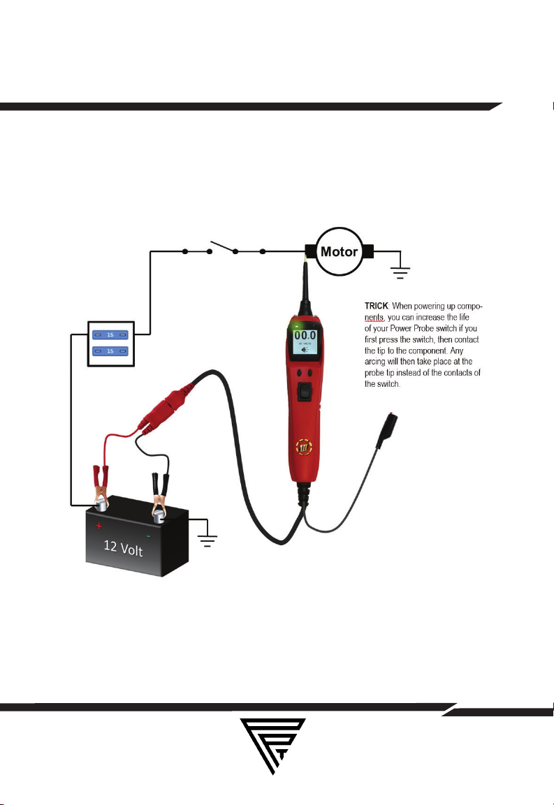
IMPORTANT TIP: When powering-up components, you can increase the life of your Power Probe switch if you first press the
switch, then contact the tip to the component. The arcing will
take place at the tip instead of the contacts of the switch.
4
WWW.POWERPROBETEK.COM
Page 5

HOOK UP AND QUICK SELF-TEST
Unroll the Power Probe cable. Connect the RED battery hookup clip to the POSITIVE terminal of the vehicle’s battery. Connect the BLACK battery hook-up clip to the NEGATIVE terminal of the vehicle’s battery. When the PP3EZ is first connected
to a battery (power source), it will sound a quick start up tone
and then go into Voltmeter Mode (See Mode #1) and the 2
bright white LEDs (dual headlights) will be on to illuminate the
test area of the probe tip.
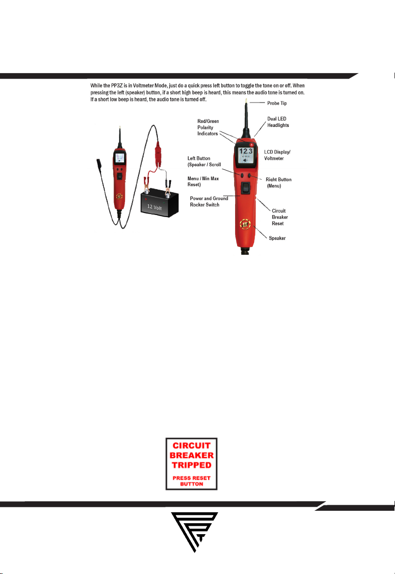
TURNING AUDIO TONE ON & OFF
While the PP3EZ is in Voltmeter Mode, press the left button to
toggle the tone on or o. When the left button is pressed, if a
short high beep is heard, this means the audio tone is turned
on. If a short low beep is heard, the audio tone has turned o.
WWW.POWERPROBETEK.COM
5
Page 6
TURNING AUDIO TONE ON & OFF
CIRCUIT BREAKER
In Voltmeter Mode (Mode #1) with the circuit breaker tripped,
the display will show “Circuit Breaker Tripped”(see page 11-12
for detail) All other functions of the PP3EZ are still active. This
means that you can still probe a circuit and observe the voltage reading. When the circuit breaker is tripped, the PP3EZ
will NOT be able to conduct battery current to the tip even
when the power switch is pressed. Intentionally tripping the
breaker and using the PP3EZ to probe can be considered an
added precaution against accidental pressing of the power
switch.
WWW.POWERPROBETEK.COM
6
Page 7

INTRODUCTION TO “EZ”
The Power Probe 3EZ is the latest addition to the Power
Probe line of circuit testers. It includes all the powerful testing
modes and features of the Power Probe 3S and now includes
2 new modes- EZ Learning Mode and EZ Diagnostics Mode.
EZ Learning Mode will guide you through a step by step
familiarization of the PP3EZ, showing you how to operate the
PP3EZ and how the probe responds in certain testing conditions.
EZ Diagnostics Mode will help guide you through specific
vehicle or component tests and let you know if readings obtained are acceptable or outside of the desired specification.
EZ Learning Mode – Scroll the Menu down using the Left
Button until EZ LEARNING is highlighted on the menu. Select
EZ LEARNING by pressing the Right Button. EZ Learning will
now take you through a step by step process illustrating how
the probe responds and the dierent types of readings that
can be obtained. This mode is to be used for familiarization
and guidance only and is not a mode used for actual circuit
testing.
Once EZ LEARNING mode is selected, it must be scrolled
through from start to finish before it will exit EZ LEARNING
mode. You can also exit EZ Learning by disconnecting power from the probe and the probe will enter normal test mode
when re-connected. NOTE: If you see a flashing screen in the
menu it means go to that selection and press enter.
7
WWW.POWERPROBETEK.COM
Page 8

EZ DIAGNOSTICS
EZ Diagnostic Mode – Scroll the Menu down using the Left
Button until EZ DIAGNOSTICS is highlighted on the menu. Select EZ DIAGNOSTICS by pressing the Right Button. EZ DIAGNOSTICS are preset test modes for dierent vehicle system
tests.
The available tests listed are: Battery Check, Charge Test,
Fuse Test, Voltage Test, Component Test, 5V Ref.
Each test section includes a readable QR code that will access online video content explaining the test procedure.
5V REF mode is used together with the Power Probe Tek 5V
Adapter Tip (# PPT5VA). With the Adapter Tip installed on the
probe and applying power, the probe will no longer output full
battery voltage. The 5 Volt Adapter will only output a current
limited 5V that can be used as a reference voltage to safely
power and test sensor and computer circuits.
FOR FULL EXPLANATIONS OF EACH TESTING MODE AND
SCREEN PLEASE GO TO:
www.powerprobetek.com/ezdiagnostics/ or scan the below
QR code:
WWW.POWERPROBETEK.COM
8
Page 9

TESTING SECTION
Continuity testing 10
Activating components out of vehicle’s electrical system 11
Testing trailer lights and connections. 13
Activating electrical components in the Vehicle 14
Activating electrical components with Ground 16
Checking for bad ground contacts 18
Following & Locating Short Circuits 18
WWW.POWERPROBETEK.COM
9
Page 10
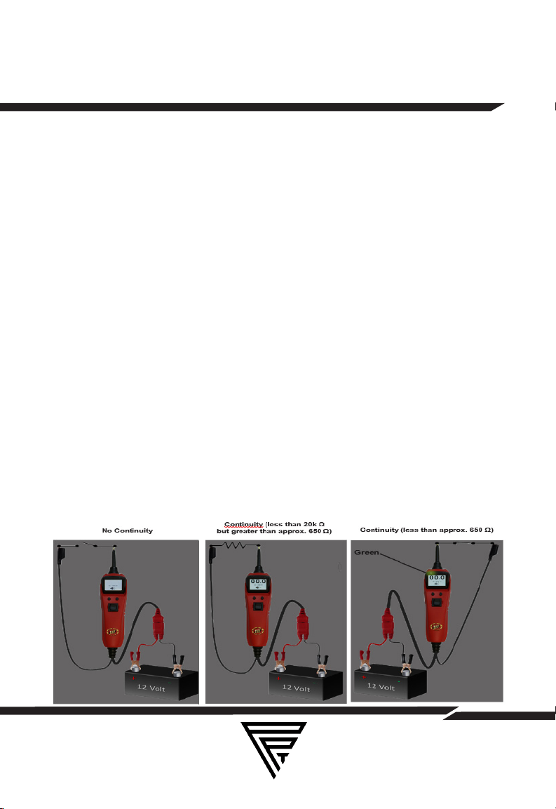
CONTINUITY TESTING
While the PP3EZ is in Voltmeter Mode, and by using the Power Probe tip in connection with chassis ground or the auxiliary
ground lead, continuity can be tested on wires and components attached or disconnected from the vehicle’s electrical
system.
The PP3EZ indicates continuity using 2 resistance levels.
When the Power Probe tip has a resistance to ground less
than 20K Ohms but greater than approx. 650 Ohms the LCD
will indicate “00.0” volts but no Green “-” LED. But when the
resistance to ground less than approx. 650 Ohms the LCD will
indicate “00.0” volts and also the Green “-” LED. The higher
resistance continuity function is useful for checking Spark Plug
Wires, (disconnected from ignition) Solenoids and magnetic
pickup coils, and the lower resistance continuity for testing relay coils and wiring. However the best way to prove continuity
of connections to either Ground or Battery is to power up the
connection using the Power Switch. If the Circuit Breaker trips
you know that you have a good solid low resistance connection.
WWW.POWERPROBETEK.COM
10
Page 11

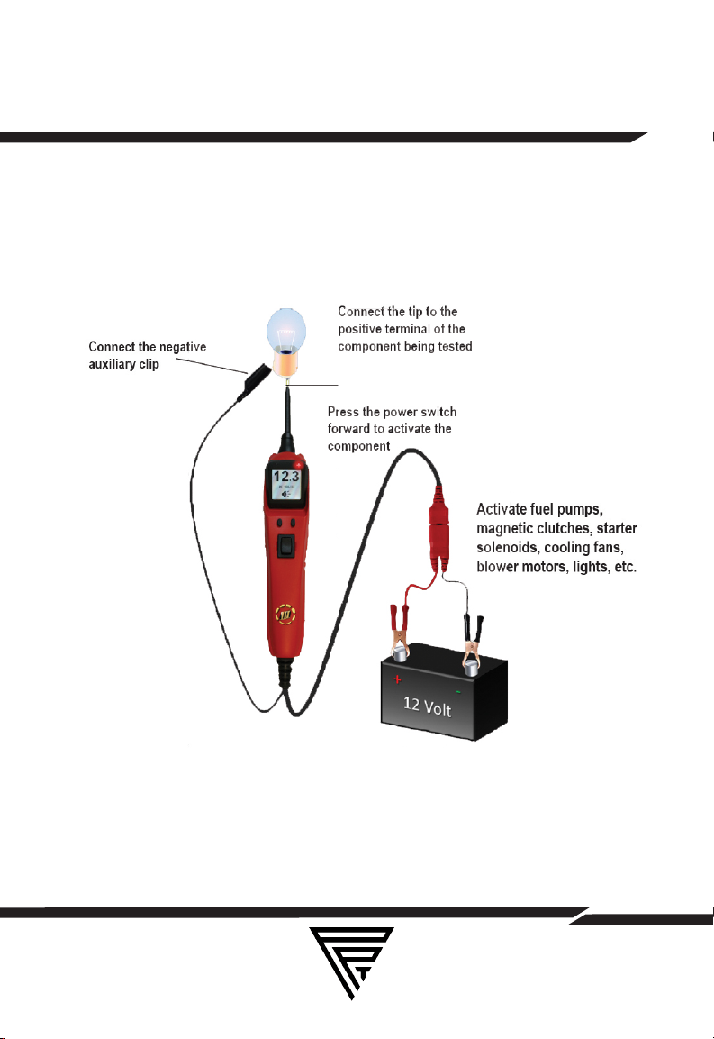
ACTIVATING COMPONENTS IN HAND
While the PP3EZ is in Voltmeter Mode and by using the Power
Probe tip in connection with the auxiliary ground lead, components can be activated right in your hand, thereby testing
their function. Connect the negative auxiliary clip to the negative terminal or ground side of the component being tested.
Contact the probe to the positive terminal of the component,
the green negative sign “-“ LED indicator should light GREEN
indicating continuity through the component.
While keeping an eye on the green LED negative sign, quickly
depress and release the power switch forward (+). If the green
negative sign “-“ LED went out and the red positive sign “+”
came on, you may proceed with further activation. If the green
negative sign “-“ LED went o at that instant or if the circuit
breaker tripped, the Power Probe has been overloaded. This
could happen for the following reasons:
• The contact you are probing is a direct ground or negative
voltage.
• The component you are testing is short-circuited.
•The component is a very high current component (i.e., starter
motor).
If the circuit breaker is tripped, reset it by waiting for it to cool
down (15 sec.) and then depressing the reset button.
11
WWW.POWERPROBETEK.COM
Page 12
ACTIVATING COMPONENTS IN HAND
WWW.POWERPROBETEK.COM
12
Page 13
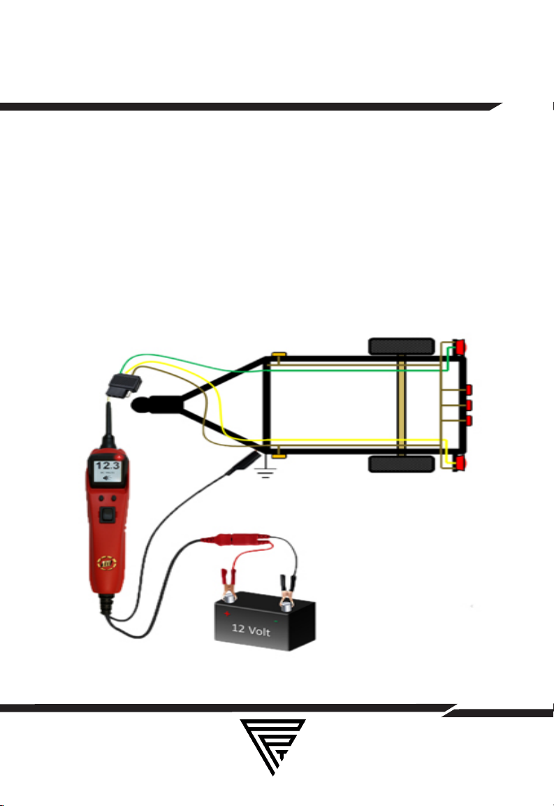
TRAILER LIGHT CONNECTIONS
1. Connect the PP3EZ to a good battery.
2.Clip the auxiliary ground clip to the trailer ground.
3. Probe the contacts at the jack and then apply voltage to
them. This lets you check the function and orientation of the
connector and trailer lights. If the circuit breaker tripped, that
contact is likely a ground. Reset the circuit breaker by letting
it cool down (15 sec.) and depressing the reset button until in
clicks into place.
WWW.POWERPROBETEK.COM
13
Page 14

ACTIVATING COMPONENTS ON
VEHICLE
To activate components with positive (+) voltage: Contact
the probe tip to the positive terminal of the component, the
green negative sign “-” LED should light. Indicating continuity
to ground. While observing the green indicator, quickly depress and release the power switch forward (+). If the green
indicator went out and the red positive sign (+) LED came on,
you may proceed with further activation. If the green indicator went o at that instant or if the circuit breaker tripped, the
Power Probe has been overloaded. This could happen for the
following reasons:
•The contact is a direct ground.
•The component is short-circuited.
•The component is a high current component (i.e., starter
motor).
If the circuit breaker tripped, reset it by allowing it to cool
down (15 sec.) and then depress the reset button.
Warning: Haphazardly applying voltage to certain circuits can
cause damage to a vehicle’s electronic components. Therefore, it is strongly advised to use the vehicle manufacturer’s
schematic and diagnosing procedure while testing.
14
WWW.POWERPROBETEK.COM
Page 15
ACTIVATING COMPONENTS ON
VEHICLE
WWW.POWERPROBETEK.COM
15
Page 16

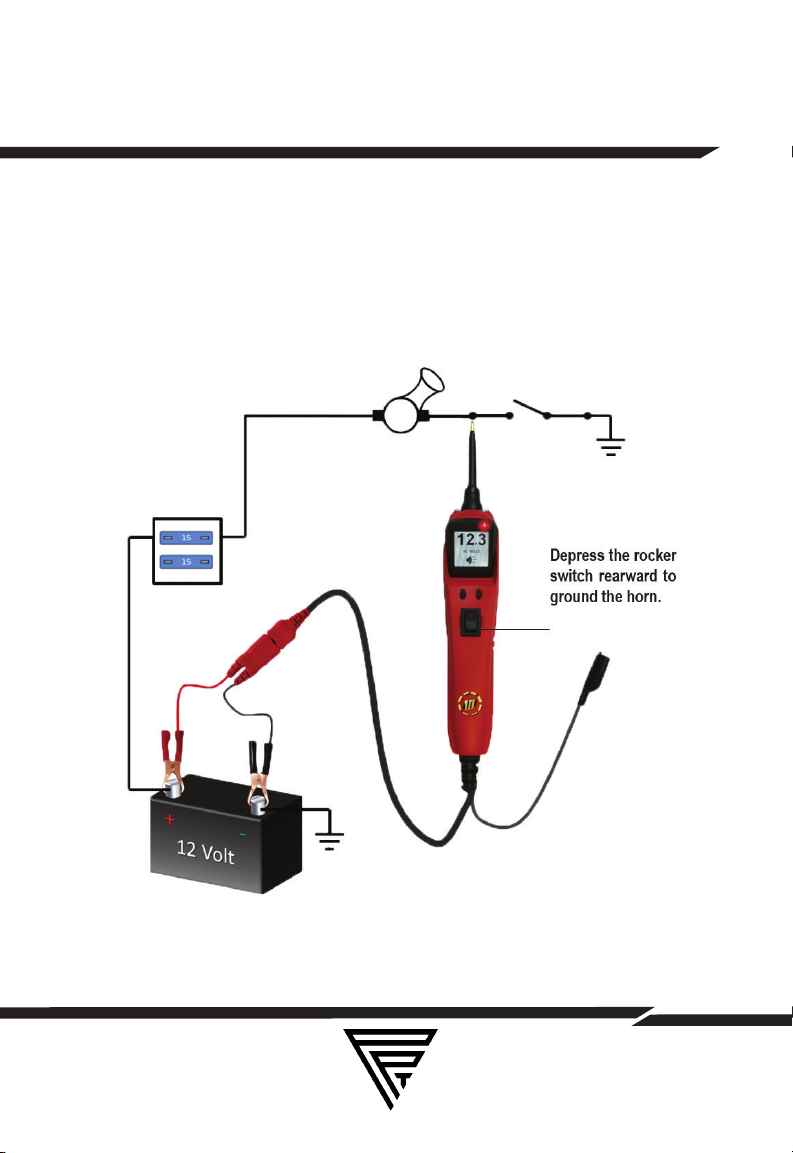
ACTIVATING COMPONENTS WITH
GROUND
Contact the probe tip to the negative terminal of the component, the LED indicator should light RED. While observing red
positive sign “+” LED, quickly depress and release the power
switch rearward (-). If the red indicator went out and the green
negative sign (-) came on you may proceed with further activation. If the green indicator went o at that instant or if the
circuit breaker tripped, the Power Probe has been overloaded. This could have happened for the following reasons:
• The contact is a direct positive voltage.
• The component is short-circuited.
• The component is a very high current component (i.e., starter
motor).
If the circuit breaker tripped, reset it by allowing it to cool
down (15 sec.) and then depress the reset button.
WARNING: With this function, if you are contacting a protected
circuit, a vehicle’s fuse can be blown or tripped if you apply
ground to it.
16
WWW.POWERPROBETEK.COM
Page 17
ACTIVATING COMPONENTS WITH
GROUND
WWW.POWERPROBETEK.COM
17
Page 18

CHECKING FOR BAD GROUNDS
Probe the suspected ground wire or contact with the probe
tip. Observe the green negative sign “-” LED. Depress the
power switch forward then release. If the green negative sign
“-” LED went out and the red positive sign “+” came on, this is
not a true ground.
If the circuit breaker tripped, this circuit is more than likely a
good ground. Keep in mind that high current components
such as starter motors will also trip the circuit breaker.
FOLLOWING AND LOCATING SHORT
CIRCUITS
In most cases a short circuit will appear by a fuse or a fusible
link blowing or an electrical protection device tripping (i.e.,
a circuit breaker). This is the best place to begin the search.
Remove the blown fuse from the fuse box. Use the Power
Probe tip to activate and energize each of the fuse contacts.
The contact which trips the PP3EZ circuit breaker is the shorted circuit. Take note of this wire’s identification code or color.
Follow the wire as far as you can along the wiring harness, for
instance if you are following a short in the brake light circuit
you may know that the wire must pass though the wiring
harness at the door sill. Locate the color-coded wire in the
harness and expose it. Probe through the insulation with the
Power Probe tip and depress the power switch forward to activate and energize the wire. If the Power Probe circuit breaker tripped you have verified the shorted wire. Cut the wire and
energize each end with the Power Probe tip. (continued)
WWW.POWERPROBETEK.COM
18
Page 19

FOLLOWING AND LOCATING SHORT
CIRCUITS
The wire end which trips the Power Probe circuit breaker
again is the shorted circuit and will lead you to the shorted
area. Follow the wire in the shorted direction and repeat this
process until the short is located. The Power Probe ECT3000
uses a wireless non-contact technique that guides you to the
short/open location.
RED/GREEN POLARITY INDICATORS &
TONES
The “RED/GREEN Polarity Indicator” lights-up when the probe
tip voltage matches the battery voltage within ± 0.5 volts. This
means that if you contact a circuit that is not a good ground
or a good hot, you will see this instantly by the “RED/GREEN
Polarity Indicator” NOT lighting. The Audio Tone runs parallel
to the “RED/GREEN Polarity Indicator and will also NOT react
when contacting a circuit that does not match the battery voltage within ± 0.5 volts. This is a very useful function that automatically alerts you of any excessive voltage drop in the circuit.
FLIP SCREEN FUNCTION
The PP3EZ has the adiitional ability to change the orientation
of the display screen. Press the right menu button to bring up
the menu, then use the left button to scroll to “FLIP SCREEN”
then press the right button again. The display screen will now
be inverted 180 degrees allowing the user to select either
display mode depending on the testing situation. Selecting
the “FLIP SCREEN” function again to restore the display to it’s
original orientation.
19
WWW.POWERPROBETEK.COM
Page 20

MODES
The Power Probe 3EZ has been designed to work the same
as the previous Power Probe circuit testers. Using the advanced features and modes is optional. However, understanding them will expand your diagnosing capabilities. The LCD
display indicates voltage levels of the circuit along with an
identifying symbol showing you what mode it is in. The additional features contain 5 new modes which give you specific
information about how the circuit is reacting.
The 5 Modes menu can be accessed by depressing the right
Menu button. Then press the left button to select the needed
test mode. Once the desired test mode is highlighted on the
menu screen, press the right Mode button to enter that test
mode.
Mode #1 Voltmeter Mode: While the PP3EZ is in “Voltmeter
Mode” and the probe tip is floating (not contacting a circuit),
the display will show “DC VOLTS.” If the audio tone is turned
on you will see a speaker symbol in the lower part of the display. Once you contact the probe tip to a circuit the LCD display will indicate the average voltage level of the circuit. The
red/green polarity indicator (See section Red/Green Polarity
Indicator and Audio Tone) will respond also, showing whether
the circuit is positive or negative. A secondary feature in this
mode is the peak to peak threshold detection and signal monitoring. When contacting a signal generating circuit such as a
speaker wire with audio signals on it, the PP3EZ detects the
peak to peak signals and displays the peak to peak voltage
WWW.POWERPROBETEK.COM
20
Page 21

MODES
on the display, the sound of the signals will be monitored and
heard through the PP3EZ speaker. The peak to peak threshold
levels are pre-selected by the operator in “Mode 5”. See Mode
#5 for more information on setting threshold levels. Placing
the PP3EZ probe tip next to a sparkplug wire (NOT probing it
directly), allows you to monitor the sound of the ignition pulses
at the same time display a peak to peak reading The PP3EZ
senses the pulses in ignition wires through capacitive coupling
(DO NOT CONTACT PROBE TIP DIRECTLY TO THE SECONDARY IGNITION CIRCUIT). By monitoring each plug wire in this
way you can locate missing cylinders.
Mode #2 Peak to Peak Mode: The Peak to Peak Mode measures the dierence between the positive and negative peak
voltage levels over a 1 second period. With this feature you
can measure and monitor for example, the diode rectifier
ripple voltage in a charging system while the engine is running. The peak to peak readings will give the technician the
data necessary to determine if a diode rectifier is defective or
not. A normal peak to peak reading while testing a charging
circuit is usually under a volt. If a defective rectifier is present
the peak to peak reading will be over 1 volt and possibly over
3 volts. Probing in “Peak to Peak Mode” is the optimum mode
to display the activity of circuits such as fuel injectors, distributor pick-ups, cam and crank sensors, oxygen sensors, wheel
speed sensors, hall eect sensors, or any other pulsed DC
signal. It also measures fly back voltage of injectors to quickly
find a problem.
WWW.POWERPROBETEK.COM
21
Page 22

MODES
Mode #3 Max Peak Mode: The Max Peak Mode monitors the
probed circuit and captures the highest detected voltage.
Place the PP3EZ into Max Peak Mode by selecting MAX PEAK
from the menu. Probe the circuit and the PP3EZ instantly displays and holds the highest voltage reading. This means you
can remove the probe away from the circuit and the voltage
reading remains displayed for your reference. You can reset
the Max reading on the LCD display by doing a quick tap of
the left button.
An APPLICATION for the use of the Max Peak Mode: Let’s say
you have a circuit that is supposed to be o and is suspected of turning on inappropriately or getting a signal for some
reason. Probing the circuit and monitoring it in the Max Peak
Mode will instantly indicate as the circuit increases in voltage.
You can monitor the circuit while wiggling wires and pulling on
connectors to see if the voltage increases. Since the maximum voltage reading is captured and held on the display, you
can inspect the reading at a later time.
Mode #4 Min Peak Mode: The Min Peak Mode monitors a
positive circuit and displays the lowest voltage that it has
dropped to. To do this: Place the PP3EZ into Min Peak Mode
by selecting MIN PEAK from the menu. The display will show
00.0 volts if the probe tip is not connected to any voltage.
Probe the positive circuit you want to test and press the left
button to reset the voltage reading. The LCD display will show
the lowest detected voltage of the circuit. If the circuit drops
in voltage anytime, a new lowest reading will be captured and
displayed. You can continue to reset the voltage display by
WWW.POWERPROBETEK.COM
22
Page 23

MODES
pressing the left button as often as necessary.
An APPLICATION for the use of the Min Peak Mode: Lets say
you have a circuit that is suspect of losing a connection and
the voltage drops, causing something to turn o or malfunction. Probing the circuit and monitoring it in Min Peak Mode
will instantly indicate as the circuit drops in voltage. You can
monitor the circuit while wiggling wires and pulling on connectors to see if the voltage drops. Since the minimum voltage
reading is captured and held on the display, you can inspect
it at a later time. You could also perform a battery load test by
monitoring the vehicle’s lowest battery voltage while cranking
the starter.
Mode #5 AC Threshold Level Setting for the Peak to Peak Detection in Voltmeter Mode” (Mode #1) This mode is only used
to adjust the threshold voltage in “Voltmeter Mode” for Peak
to Peak Detection and Signal Monitoring. To set the threshold level for the peak to peak detection in “Voltmeter Mode”,
press right menu button to bring up the menu selections, then
use the left button to highlight “AC THRESHOLD”, then press
the right button again to display the AC Threshold voltage
setting. The peak to peak threshold voltage settings loop incrementally from 50.0 to 0.2, to 0.5, to 1.0, to 2.0, to 5.0, to 10.0,
and return back to 50.0 again. An audio installer would find the
0.2v setting convenient. Once you select the desired threshold voltage, press and hold the right menu button again to
return to Voltmeter Mode (Mode #1). This AC Threshold setting
determines the amount of AC voltage required to automatically
switch to Peak to Peak Mode and activate the speaker to allow
audible monitoring of the AC signal
WWW.POWERPROBETEK.COM
23
Page 24

MODES
WWW.POWERPROBETEK.COM
24
Page 25

SPECIFICATIONS
Storage temperature/humidity: -20 to 700C, 70% RH max
Operating temperature/humidity: -10 to 500C, 70% RH max
Pollution degree: 2
DC Voltage 0 to +70 Volts +1 digit
P-P Voltage .............. 0 to +70 Volts
Frequency Response ......... 10Hz to 10kHz (for tone pass
through)
P-P display ........... 15Hz Square Wave
35Hz Sine Wave
DC Voltmeter Mode - Continuity to ground
- First Level - display is enabled less than 20K Ω
- Second Level green LED is enabled less than approx. 650 Ω
- + Peak Detector Response
- Single event capture less than 200mS pulse width
- Repetitive events less than 1mS pulse width
- Peak to Peak Mode ....... 0 to +70 Volts + 1 digit
- 4Hz to over 500kHz Square Wave input
- 4Hz to over 250kHz Sine Wave input
Over Volt Warning
If the probe tip connects to a voltage greater than +70 Volts
the display will show an “Over Volt” warning.
Remove the probe tip immediately to prevent internal damage
to the tool.
Over Load Warning
If the probe is connected to a battery with voltage greater than
34VDC the display will show an “Over Load” warning.
25
WWW.POWERPROBETEK.COM
Page 26

SPECIFICATIONS
WWW.POWERPROBETEK.COM
26
Page 27

REPLACEMENT PARTS
The Power Probe 3EZ is engineered for years of reliable
service. Some components can wear out over time with heavy
use. Replacement parts can be obtained from your tool dealer
or by contacting Power Probe Tek’s Technical Support department at 1-800-655-3585 or email to support@pp-tek.com
Replacement Probe Tips (# PPTK0024)
The Rocker Switch (# PPTK0021) can be easily replaced in the
field as the switch contacts can wear over time. Remove the
Rocker Switch by using a flat pry tool such as a screwdriver
and carefully pry the switch up from the probe face. Place the
new Rocker Switch straight into the switch opening and press
down firmly until the new switch is flush with the probe face.
Replacement Battery Clip Set (# PPTK0025)
POWER PROBE WARRANTY
Power Probe products undergo a strict quality control inspection for workmanship, function, and safety before leaving the
factory. From the date of purchase, we will warranty/ repair
Power Probe products for one (1) year against defects in parts
and workmanship. All repairs due to misuse will be charged a
fee not to exceed the cost of the tool. All warranty units must
be accompanied by a copy of the original sale receipt. In the
event of a malfunction or a defective unit, please call or write
Power Probe Technical Support or your Power Probe dealer.
27
WWW.POWERPROBETEK.COM
Page 28

NOTES:
760 Challenger Street Brea, California 92821
Phone: 800-655-3585 Local: 714-990-9443
fax: 714-990-9478
support@pp-tek.com
WWW.POWERPROBETEK.COM
28
Page 29

Power Probe 3EZ
5000815
INTRODUCCION
Gracias por comprar el Power Probe 3EZ (PP3EZ). El PP3EZ
incluye todas las funciones poderosas de prueba y Caracteisticas del Power probe 3S y ahora incluye 2 funciones nuevas:
function de aprendizaje EZ y function de diagnostico EZ. El
PP3EZ te ayuda repidamente a diagnosticar los sistemas
eléctricos automotrices de 12 a 24 voltios. Después de conectar las pinzasdel PP3EZ a la batería del vehículo, el técnico
automotriz puededeterminar de un vistazo, el nivel de voltaje
y la polaridad de uncircuito sin necesidad de un voltímetro.
El interruptor de encendido permite que el técnico automotriz conduzca una corrientede batería positiva o negativa a
la punta para activar y probar la función de los componentes
eléctricos sin perder tiempo con loscables de corriente.
WWW.POWERPROBETEK.COM
Page 30

CONTINUA LA INTRODUCCION
Le permite seguir y localizar corto circuitos sin desperdiciar
los preciados fusibles. El Power Probe también puede probar
la continuidad con la ayuda de su cable auxiliar sin correr hacia la batería, ya que de lo contrario tendría que usar con un
probador de corriente regular. El cable de 20 pies del PP3EZ
le permite realizar pruebas a lo largo de todo el vehículo sin
buscar constantemente conexiones a tierra. No use el equipo
para mediciones en CAT II, CAT III y CAT IV. Una necesidad
absoluta para todos los técnicos automotrices que buscan
una solución rápida y precisa para el diagnóstico de sistemas
eléctricos.
Antes de usar el Power Probe 3EZ, lea atentamente el manual
de instrucciones.
Si el equipo se utiliza de una manera no especificada por el
fabricante, la protección proporcionada para el equipo puede
verse afectada.
¡Advertencia! Cuando se presiona el interruptor de corriente
PP3EZ, la corriente / voltaje de batería se conduce directamente a la punta, lo que puede causar chispas al entrar en
contacto con tierra o ciertos circuitos. Por lo tanto, el Power
Probe puede encender estos vapores. Use la misma precaución que cuando usa un soldador de arco.
WWW.POWERPROBETEK.COM
30
Page 31

CONTINUA LA INTRODUCCION
El producto no es resistente al agua, evite el contacto con el
agua durante la operación.
Si los cables de prueba necesitan ser reemplazados, debe
usar uno nuevo que cumpla con la norma EN 61010-031.
El Power Probe 3EZ NO debe usarse con 110 / 220V de tu
casa, solo para uso con sistemas de 12-24v.
WWW.POWERPROBETEK.COM
31
Page 32

TABLA DE CONTENIDO - INDICE
Conexion y Auto Prueba Rapida 33
Activacion y Desactivasion del Tono Auditivo 34
Protector de Circuito (Disyuntor) 34
Introduccion de “EZ” 35
Guia de Diagnosticos 36
Seccion de Diagnostico 37
Probando Continuidad 38
Activando Componentes Eléctricos fuera de el Vehiculo 39
Prueba de Luces y Conexiones de un Remolque 41
Activacion de Componentes Eléctricos en el Vehiculo 42
Activando Componentes Eléctricos con Tierra 44
Probando Contactos de Tierra Malos 46
Localizando y Siguiendo Circuitos en Corto 46
Indicador Rojo/Verde y Tono de Audio 47
Funcion de el Giro de Pantalla 47
Especificaciones 53
Piezas de Repuesto 65
Garantia de el Power Probe 55
CONSEJO IMPORTANTE: Al encender los componentes,
puede aumentar la vida útil de su interruptor Power Probe si
primero presiona el interruptor y luego contacta la punta con
el componente. El arco se realizará en la punta en lugar de los
contactos del interruptor.
32
WWW.POWERPROBETEK.COM
Page 33

CONEXIÓN Y AUTO PRUEBA RÁPIDA
Desenrolle el cable de la sonda de alimentación. Conecte
el clip de conexión de la batería ROJA al terminal POSITIVO
de la batería del vehículo. Conecte el clip de conexión de la
batería NEGRA al terminal NEGATIVO de la batería del vehículo. Cuando el PP3EZ se conecta por primera vez a una batería
(fuente de alimentación), sonará un tono de inicio rápido y
luego pasará al modo de voltímetro (consulte Modo # 1) y los
2 LED blancos brillantes (dos luces) se encenderán para iluminar el área de prueba de la punta de la sonda.
WWW.POWERPROBETEK.COM
33
Page 34

ACTIVACION Y DESACTIVASION DEL TONO AUDITIVO
PROTECTOR DE CIRCUITO
En la funcion Voltímetro (funcion #1) con el protector de circuito activado, la pantalla mostrará “CIRCUITO PROTECTOR
ACTIVADO” (vea la página 11-12 para más detalles) Todas las
otras funciones del PP3EZ están activas. Esto significa que
aún puede probar un circuito y observar la lectura de voltaje. Cuando se activa el interruptor de energia, el PP3EZ NO
podrá conducir la corriente de la batería a la punta, incluso
cuando se presione el interruptor de energia. Si presionas el
interruptor de energia accidentalmente o intencionadamente
y usas el PP3EZ para probar se puede considerar una precaución adicional y no provera energia hasta que sea reactivado
el protector de circuito.
WWW.POWERPROBETEK.COM
34
Page 35

INTRODUCCION A “EZ”
El Power Probe 3EZ es la última adición a la línea de probadores
de circuitos Power Probe. Incluye todos Las funciones potentes
de prueba del Power Probe 3S y ahora incluye 2 funciones nuevas: funcion de APRENDIZAJE EZ y funcion de DIAGNOSTICO EZ.
La funcion de APRENDIZAJE EZ te guiará para que te pudas
familiarisar paso a paso con la herramienta, y que te mostrará
cómo operar el PP3EZ y cómo responde en ciertas condiciones
de prueba.
La funcion de Diagnóstico EZ te guiara a través de pruebas específicas de vehículos o componentes y le permitirá saber si las
lecturas obtenidas son aceptables o están fuera de las especificaciones deseadas.
La funcion de APRENDIZAJE EZ: En el menu principal navegar
hacia abajo con el botón izquierdo hasta que se resalte APRENDIZAJE EZ. Seleccione APRENDIZAJE EZ presionando el botón
derecho. APRENDIZAJE EZ ahora te guiará por un proceso paso
a paso que ilustra cómo responde la herramienta y los diferentes
tipos de lecturas que se pueden obtener. Esta funcion se debe
usar solo para familiarisar y orientar, y no es una funcion que
puedas utilizar para las pruebas de circuitos reales.
Una vez que se selecciona la funcion APRENDIZAJE EZ, se debe
desplazar de principio a fin para poder salir de la funcion. También puede salir de la funcion de APRENDIZAJE desconectando
la herramienta y cuando vuelva a conectar entrará en la funcion
de prueba normal. NOTA: Si ve una pantalla parpadeante en el
menú, significa que debe ir a esa selección y presionar boton
izquierdo.
WWW.POWERPROBETEK.COM
35
Page 36

DIAGNOSTICO EZ
La funcion de DIAGNOSTICO EZ: En el menu principal
navegar hacia abajo con el botón izquierdo hasta que se resalte DIAGNOSTICO EZ en el menú. Seleccione DIAGNOSTICO EZ presionando el botón derecho. DIAGNOSTICO EZ son
funciones de prueba preestablecidos para diferentes pruebas
del sistema eléctricos del vehículos.
Las pruebas disponible son: Prueba de la batería, Prueba de
carga, Prueba de fusible, Prueba de voltaje, Prueba de componente, Referencia de 5 voltios.
Cada sección de prueba incluye un código QR legible que
accesa al contenido de un video que explica el procedimiento de prueba.
La funcion de referencia de 5 voltios se usa junto con la punta
del adaptador ESPECIAL Power Probe Tek 5V. (N / P PPT5VA)
Con la punta del adaptador instalada en la herramienta y aplicando energia positiva, la punta ya no superará el voltaje total
de la batería. El adaptador de 5 voltios solo generará una corriente de 5 voltios limitada que se puede usar como voltaje
de referencia para alimentar y probar de manera segura los
circuitos del sensor y la computadora.
PARA OBTENER LAS EXPLICACIONES TOTALES DE CADA
FUNCION DE PRUEBA Y PANTALLA, CONSULTE:
www.powerprobetek.com/ezdiagnostics/ o si tienes acceso
de lectura de código QR:
WWW.POWERPROBETEK.COM
36
Page 37

FUNCIONES DE PRUEBAS
Prueba de continuidad 38
Activación de componentes fuera del sistema eléctrico del
vehículo 39
Prueba de luces y conexiones del remolque 41
Activación de componentes eléctricos en el vehículo 42
Activación de componentes eléctricos con Ground 44
Comprobando contactos de tierra malos 46
Siguiendo y Localizando Corto circuitos 46
WWW.POWERPROBETEK.COM
37
Page 38

PRUEBA DE CONTINUIDAD
Mientras que el PP3EZ está en la funcion Voltímetro y utilizando la punta de Power Probe en conexión con la tierra del chasis o el cable de tierra auxiliar, se puede probar la continuidad
de los cables y componentes conectados o desconectados
del sistema eléctrico del vehículo.
El PP3EZ indica continuidad utilizando 2 niveles de resistencia. Cuando la punta de la herramienta de alimentación tiene
una resistencia a tierra inferior a 20 K ohmios, pero superior o
aprox. 650 ohmios la pantalla LCD indicará “00.0” voltios pero
no verde “-” LED. Pero cuando la resistencia esta a menos de
650 ohmios la pantalla LCD indicará “00.0” voltios y también el
LED verde “-”. La función de continuidad de mayor resistencia
es útil para verificar los cables de la bujía, (desconectados de
las bujias) los solenoides y las bobinas de encendido, y la continuidad de resistencia más baja para probar rele de encendido y el cableado. Sin embargo, la mejor manera de probar la
continuidad de las conexiones a tierra o batería es encender la
conexión con el interruptor de energia. Si el Circuito de proteccion se activa, sabrá que tiene una buena conexión sólida de
baja resistencia.
WWW.POWERPROBETEK.COM
38
Page 39

ACTIVANDO COMPONENTES A MANO
Mientras que el PP3EZ se encuentra en la funcion Voltímetro
y utilizando la punta de la herramienta de alimentación en
conexión con el cable de tierra auxiliar, los componentes se
pueden activar directamente en su mano, probando así su
funcion
Conecte la pinza de el cable auxiliar negativo al lado negativo o al lado de tierra del componente que se está probando.
Conecte la herramienta con la punta en la terminal positiva
del componente, el indicador verde negativo “-” LED debe
encenderse VERDE indicando continuidad a través del componente.
Mientras observas el LED verde, presione y suelte rápidamente el interruptor de alimentación de voltaje hacia adelante
(+). Si el LED verde señal negativa “-” se apagó y el signo positivo rojo “+” se encendió, puede continuar con la activación
adicional. Si el LED verde señal negativa “-” se apagó en ese
instante o si el interruptor automático se disparó, el protector
de circuito se ha sobrecargado. Esto podría suceder por las
siguientes razones:
• El contacto que está probando es una tierra directa o voltaje
negativo.
• El componente que está probando está en corto circuito.
• El componente es un componente de corriente muy alta
(como por ejemplo el motor de arranque).
Si el protector de circuito se a activado, espere a que se enfríe (15 segundos) y luego presione el botón de reactivacion.
39
WWW.POWERPROBETEK.COM
Page 40

ACTIVANDO COMPONENTES FUERA DE EL VEHICULO
WWW.POWERPROBETEK.COM
40
Page 41

CONEXIONES DE LAS LUCES DEL REMOLQUE
1. Conecte el PP3EZ a una buena batería.
2. Conecte la pinza de el cable auxiliar en la tierra del remolque.
3. Pruebe los contactos en el conector y luego aplique voltaje
a ellos. Esto le permite verificar el funcionamiento y la orientación del conector y las luces del remolque. Si el protector de
circuito se activa, ese contacto probablemente sea el problema. reactive el protector de circuito dejándolo enfriar (15
segundos) y presionando el botón de reactivacion hasta que
encaje en su lugar.
WWW.POWERPROBETEK.COM
41
Page 42

ACTIVACIÓN DE COMPONENTES EN EL VEHÍCULO
Para activar componentes con voltaje positivo (+): Ponga en
contacto la punta de la herramienta con la terminal positiva
del componente, el LED verde señal negativa “-” debería
encenderse. Indicando continuidad de la tierra. Mientras
observa el indicador verde, deprima rápidamente y suelte el
interruptor de encendido hacia adelante (+). Si se apagó el
indicador verde y se encendió el LED rojo de señal positiva
(+), puede proceder con la activación adicional. Si el indicador
verde se apagó en ese instante o si se disparó el protector
de circuito, el circuito de proteccion se ha sobrecargado. Esto
podría suceder por las siguientes razones:
• El contacto es una tierra directa.
• El componente está corto circuito.
• El componente es un componente de alta corriente (por
ejemplo, el motor de arranque).
Si el protector de circuito se activó, se puede reactivar dejándolo enfriar (15 segundos) y luego presione el botón de
reactivacion.
Advertencia: la aplicación de voltaje de una manera constante
a ciertos circuitos puede dañar los componentes electrónicos de un vehículo. Por lo tanto, se recomienda estrictamente
utilizar los esquemas del fabricante de el vehículo y los procedimiento de diagnóstico durante la prueba.
42
WWW.POWERPROBETEK.COM
Page 43

ACTIVACIÓN DE COMPONENTES EN EL VEHÍCULO
WWW.POWERPROBETEK.COM
43
Page 44

ACTIVANDO COMPONENTES CON TIERRA
Ponga en contacto la punta de la herramienta en la terminal
negativa del componente, el indicador LED debería encenderse ROJO. Mientras observa la señal rojo positivo “+”, presione y suelte rápidamente el interruptor de energia hacia atrás
(-). Si el indicador rojo se apagó y la señal verde negativo (-)
se enciendio, puede continuar con la activación adicional. Si
el indicador verde se apagó en ese instante o si se activo el
protector de circuito, la herramienta se ha sobrecargado. Esto
podría haber sucedido por las siguientes razones:
• El contacto es un voltaje positivo directo.
• El componente está en corto circuito.
• El componente es un componente de corriente muy alta
(por ejemplo, motor de arranque).
Si el protector de circuito se activó, reactivalo dejándolo enfriar (15 segundos) y luego presione el botón de reactivacion.
ADVERTENCIA: Con esta función, si está en contacto con un
circuito protegido, el fusible de un vehículo se puede fundir o
activarse si aplica tierra.
44
WWW.POWERPROBETEK.COM
Page 45

ACTIVANDO COMPONENTES CON TIERRA
WWW.POWERPROBETEK.COM
45
Page 46

PROBANDO UNA TIERRA MALA
probaremos el cable de tierra que esta en cuestion, pónga la
punta de la de la herramienta en el cable. Observe la señal
verde negativo “-” LED. Presione el interruptor de energia
hacia adelante y luego suéltelo. Si el LED verde señal negativo “-” se apagó y el signo rojo positivo “+” se encendió, este
cable no es una tierra
Si el protector de circuito se activo, este circuito es una buena
tierra. Tenga en cuenta que los componentes de alta corriente como los motores de arranque también activan el protector
de circuito.
SIGUIENDO Y LOCALIZANDO CORTO
CIRCUITOS
En la mayoría de los casos, un corto circuito aparecerá con
un fusible o un fusible de enlace fundido o un dispositivo de
protección eléctrica que se activo (es decir, unprotector de
circuito). Este es el mejor lugar para comenzar la búsqueda.
Retire el fusible quemado de la caja de fusibles. Use la punta
de la herramienta de alimentación para activar y energetizar
cada uno de los contactos del fusible. El contacto que activa el protector de circuito PP3EZ ese circuito esta en corto.
Tome nota del código o color de identificación de este cable.
Siga el cable lo más que pueda a lo largo del arnés de cableado, por ejemplo, si está siguiendo un corto circuito en el
circuito de la luz de freno, es posible que sepa que el cable
debe pasar por el arnés de cableado de la puerta. Ubique
el cable con código de color en y saquelo de el arnés. Haga
una prueba a través del aislamiento con la punta de la herramienta de alimentación y presione el interruptor de encendido hacia adelante para activar y energetizar la cable.
Si se activo el protector del circuito de la herramienta de
alimentación, ha verificado que el cable esta corto circuito.
WWW.POWERPROBETEK.COM
46
Page 47

SIGUIENDO Y LOCALIZANDO CORTO CIRCUITOS
Corte el cable y energetize cada extremo con la punta de
Power Probe. El extremo del cable que activa el protector de
circuito de la herramienta de alimentación nuevamente es el
circuito que esta en corto. Siga el cable en la dirección de
corto circuito y repita este proceso hasta que se encuentre
el corto circuito. El Power Probe ECT3000 utiliza una técnica inalámbrica sin contacto que lo guía a la ubicación de un
circuito abierto.
INDICADORES Y TONOS DE POLARIDAD ROJA /
VERDE
El “Indicador de polaridad ROJA / VERDE” se ilumina cuando
el voltaje de la punta de la herramienta coincide con el voltaje de la batería dentro de ± 0.5 voltios. Esto significa que
si pruevas con un circuito que no es una buena tierra o que
es un buen circuito positivo, lo verás instantáneamente con
el “Indicador de polaridad ROJO / VERDE” sin iluminación. El
Tono de Audio no se escucha al mismo tiempo que el “Indicador de Polaridad ROJO / VERDE” y tampoco reaccionará
cuando entre en contacto con un circuito que no concuerde
con el voltaje de la batería dentro de ± 0.5 voltios. Esta es una
función muy útil que le avisa automáticamente de cualquier
caída de voltaje excesiva en el circuito.
FUNCIÓN DE GIRO DE PANTALLA
El PP3EZ tiene la capacidad adicional de cambiar la orientación
de la pantalla de visualización. Presione el botón derecho del
menú para que aparezca el menú, luego use el botón izquierdo
para navegar a “ GIRO DE PANTALLA “ y luego presione el botón
derecho otra vez. La pantalla de visualización se invertirá 180
grados, permitiendo al usuario seleccionar cualquier modo de visualización dependiendo de la situación de prueba. Seleccionando la función “GIRO DE PANTALLA” nuevamente para restaurar la
visualización a su orientación original.
47
WWW.POWERPROBETEK.COM
Page 48

FUNCIONES
El Power Probe 3EZ ha sido diseñado para funcionar de la
misma manera que los probadores de circuitos Power Probe
anteriores. El uso de funciones avanzadas es opcional. Sin
embargo, comprenderlos ampliará sus capacidades de diagnóstico. La pantalla LCD indica los niveles de voltaje del
circuito junto con un símbolo de identificación que le muestra
en qué funcion se encuentra. Las funciones adicionales contienen 5 funciones nuevas que le brindan información específica sobre cómo está reaccionando el circuito.
Se puede navegar el menú de 5 funciones presionando el
botón de Menú derecho. Luego presione el botón izquierdo
para seleccionar la funcion de prueba necesaria. Una vez que
al funcion de prueba es seleccionada en la pantalla de menú,
presione el botón de funcion derecha para ingresar a ese
funcion de prueba.
Funcion # 1 Voltimetro: Mientras el PP3EZ está en la “funcion
Voltimetro” y la punta de la herramienta no tocando algun
circuito, la pantalla mostrará “DC VOLTS”. Si el tono de audio
está activado, verá un símbolo de altavoz en la parte inferior
de la pantalla. Una vez que conecta la punta de la herramienta con un circuito, la pantalla LCD indicará el nivel de voltaje
promedio del circuito. El indicador de polaridad rojo / verde
(consulte la sección Indicador de Polaridad Rojo / Verde y
Tono de Audio) también responderá, mostrando si el circuito
es positivo o negativo. Una característica secundaria en este
modo es la detección de pico a pico y el monitoreo de la
señal. Al conectar un circuito generador de señal, como un
cable de una bocina con señales de audio, el PP3EZ detecta
las señales de pico a pico y muestra el voltaje de pico a pico
(CONTINUACIÓN)
WWW.POWERPROBETEK.COM
48
Page 49

MODES
en la pantalla, el sonido de las señales serán monitoreadas y
escuchadas a través del altavoz PP3EZ. Los niveles de limite
pico a pico son preseleccionados por el operador en “Funcion
5”. Vea funcion # 5 para más información sobre cómo establecer niveles de limite. Colocando la punta de la herramienta
PP3EZ al lado de un cable de bujía (NO lo prueba directamente), le permite monitorear el sonido de los pulsos de encendido al mismo tiempo mostrara una lectura de pico a pico
El PP3EZ detecta los impulsos en los cables de encendido a
través del acoplamiento capacitivo (NO CONECTE CON LA
PUNTA DE LA HERRAMIENTA DIRECTAMENTE AL CIRCUITO
DE ENCENDIDO SECUNDARIO). Al monitorear cada cable
de enchufe de esta manera, puede localizar los cilindros que
estan fallando.
Funcion # 2 PICO A PICO: la funcion pico a pico mide la diferencia entre los niveles en una onda de frecuencia positivo y
negativo durante el período de 1 segundo. Con esta función,
puede medir y controlar, por ejemplo, el voltaje de ondulación
del rectificador de diodos en un sistema de carga mientras el
motor está funcionando. Las lecturas pico a pico proporcionarán al técnico los datos necesarios para determinar si un rectificador de diodos es defectuoso o no. Una lectura normal de
pico a pico mientras se prueba un circuito de carga generalmente está bajo voltios. Si hay un rectificador defectuoso, la
lectura de pico a pico será de más de 1 voltio y posiblemente
de más de 3 voltios. La prueba en el “Funcion de pico a pico”
es el modo óptimo para mostrar la actividad de circuitos tales
como inyectores de combustible, captadores de distribución,
sensores de leva y cigüeñal, sensores de oxígeno, sensores
de velocidad de rueda, sensores de efecto Hall o cualquier
otro pulso Señal DC También mide el voltaje de retorno de los
inyectores para encontrar rápidamente un problema.
WWW.POWERPROBETEK.COM
49
Page 50

MODES
Funcion # 3 La funcion Pico Max: esta funcion monitorea el
circuito probado y captura el voltaje más alto detectado. Coloque el PP3EZ en la funcion MAX PEAK en el menú. Pruebe
el circuito y el PP3EZ instantáneamente visualiza y mantiene
la lectura de voltaje más alta. Esto significa que puede desconectar la punta de la herramienta del circuito y la lectura
de voltaje permanece visualizada para su referencia. Puede
restablecer la lectura máxima en la pantalla LCD haciendo un
toque rápido con el botón izquierdo.
Una APLICACIÓN para el uso de la funcion Pico Máx: digamos
que tiene un circuito que se supone que está apagado y se
sospecha que se enciende de manera inapropiada o recibe
una señal por alguna razón. probar el circuito y monitorearlo en el modo Pico Máx. Pico indicará instantáneamente a
medida que el circuito aumenta en voltaje. Puede supervisar
el circuito mientras mueve los cables y tira de los conectores
para ver si aumenta el voltaje. Como la lectura de la tensión
máxima se captura y se mantiene en la pantalla, puede inspeccionar la lectura más adelante.
Funcion # 4 La funcion Pico Min: Esta funcion monitorea un
circuito positivo y muestra el voltaje más bajo al que ha bajado. Para hacer esto: Coloque el PP3EZ en la funcion Pico Min
seleccionando MIN PEAK en el menú. La pantalla mostrará
00.0 voltios si la punta de la herramienta no está conectada a
ningún voltaje. Pruebe el circuito positivo que desea probar y
presione el botón izquierdo para reiniciar la lectura de voltaje.
La pantalla LCD mostrará el voltaje más bajo detectado del
circuito. Si el circuito cae en voltaje en cualquier momento,
se capturará y mostrará una nueva lectura más baja. Puede
continuar reiniciando la visualización de voltaje por (CONTINUACIÓN)
WWW.POWERPROBETEK.COM
50
Page 51

MODES
presionando el botón izquierdo tantas veces como sea necesario.
UNA APLICACIÓN para el uso de la funcion pico min: digamos
que tiene un circuito que es sospechoso de perder una conexión y el voltaje cae, provocando que algo se apague o falle.
con la herramienta probando el circuito y monitorizarlo en la
funcion de pico minimo lo indicará instantáneamente a medida
que el circuito disminuya en voltaje. Puede controlar el circuito
mientras mueve los cables y tira de los conectores para ver si
cae la tensión. Como la lectura de voltaje mínima se captura y
se mantiene en la pantalla, puede inspeccionarla más adelante. También podría realizar una prueba de carga de la batería
al monitorear el voltaje más bajo de la batería del vehículo al
arrancar el motor de arranque.
Funcion # 5 AC LIMITE para la detección de pico a pico en
el modo de voltímetro “(Funcion # 1) Este modo solo se usa
para ajustar el limite de el voltage en “funcion de voltímetro”
para la detección de pico a pico y monitoreo de señal. Para
establecer el nivel limite para la detección pico a pico en la
“funcion voltímetro”, presione el botón de menú derecho para
que aparezcan las selecciones del menú, luego use el botón
izquierdo para resaltar “AC LIMITE”, luego presione el botón
derecho otra vez para mostrar la configuración de el limite de
voltaje. Los ajustes de voltaje limite de pico a pico van desde
50.0 a 0.2, a 0.5, a 1.0, a 2.0, a 5.0, a 10.0, y regresan nuevamente a 50.0. Un instalador de audio encontraría conveniente
la configuración 0.2v. Una vez que selecciona el limite de
voltaje deseado, presione y mantenga presionado el botón de
menú derecho otra vez para regresar a la funcion de voltímetro (funcion # 1). Esta configuración de AC LIMITE determina la
cantidad de voltaje de AC que se requiere para cambiar automáticamente al modo de Pico a Pico y activar el altavoz para
permitir el monitoreo audible de la señal de AC.
WWW.POWERPROBETEK.COM
51
Page 52

MODES
WWW.POWERPROBETEK.COM
52
Page 53

ESPESIFICASIONES
emperatura / Humedad de almacenamiento: -20 a 70'C, 70% HR máx.
T
Temperatura / Humedad de funcionamiento: -10 a 50'C, 70% HR máx.
Grado de contaminación: 2
Voltaje CC 0 a +70 voltios +1 dígito
Voltaje P-P de 0 a +70 voltios
Respuesta de frecuencia 10 Hz a 10 kHz (para paso de tono)
Pantalla P-P 15 Hz onda cuadrada
Onda sinusoidal de 35 Hz
Modo voltímetro DC - Continuidad a tierra
- Primer nivel - la pantalla está habilitada <20K Ω
- Segundo nivel - LED verde habilitado <650 Ω
- + respuesta del detector de picos
- Captura de evento único con un ancho de pulso menor a 200 ms
- Eventos repetitivos de menos de 1mS de ancho de pulso
- Modo pico a pico - 0 a +70 voltios +1 dígito
- Entrada de onda cuadrada de 4 Hz a más de 500 kHz
- Entrada de onda sinusoidal de 4Hz a más de 250 kHz
Advertencia de sobrevoltaje
Si la punta de la sonda se conecta a un voltaje superior a +70 voltios, la
pantalla mostrará una advertencia de “Sobrevoltaje”.
Retire la punta de la sonda inmediatamente para evitar daños internos a la
herramienta.
Advertencia sobre carga
Si la sonda está conectada a una batería con un voltaje superior a 34 V
CC, la pantalla mostrará una advertencia de “Sobrecarga”.
WWW.POWERPROBETEK.COM
53
Page 54

SPECIFICATIONS
WWW.POWERPROBETEK.COM
54
Page 55

PIEZAS DE REPUESTO
El Power Probe 3EZ está diseñado para años de servicio
confiable. Algunos componentes se pueden desgastar con el
tiempo con un uso intensivo. Se pueden obtener repuestos
con su distribuidor de herramientas o comunicándose con
el departamento de soporte técnico de Power Probe Tek al
1-800-655-3585 o por correo electrónico a support@pp-tek.
com
Punta de repuesto - (# PPTK0024)
El interruptor oscilante (# PPTK0021) se puede reemplazar
fácilmente en el campo ya que los contactos del interruptor
pueden desgastarse con el tiempo. Quite el interruptor oscilante con una herramienta de palanca plana, con un destornillador, y extraiga cuidadosamente el interruptor de la superficie
de la herramienta. Coloque el nuevo interruptor oscilante
directamente en la abertura del interruptor y presione hacia
abajo firmemente hasta que el nuevo interruptor quede al ras
con la cara de la herramienta.
Conjunto de clip de batería de repuesto (# PPTK0025)
POWER PROBE WARRANTY
Los productos Power Probe se someten a una estricta inspección de control de calidad en cuanto a mano de obra, funcionamiento y seguridad antes de abandonar la fábrica. A partir
de la fecha de compra, garantizamos / reparamos los productos Power Probe por un (1) año contra defectos en piezas y
mano de obra. A todas las reparaciones debidas a un mal uso
se les cobrará una tarifa que no excederá el costo de la herramienta. Todas las unidades de garantía deben ir acompañadas
de una copia del recibo de venta original. En caso de un mal
funcionamiento o una unidad defectuosa, llame o escriba al
Soporte técnico de Power Probe o a su distribuidor de Power
Probe.
55
WWW.POWERPROBETEK.COM
Page 56

NOTES:
760 Challenger Street Brea, California 92821
Phone: 800-655-3585 Local: 714-990-9443
fax: 714-990-9478
support@pp-tek.com
WWW.POWERPROBETEK.COM
56
 Loading...