

Page 1

This .pdf document is bookmarked
Operating Instructions and Parts Manual
Tilting Table Hollow Chisel Mortiser
Model: 719 T
Powermatic
427 New Sanford Road
LaVergne, Tennessee 37086 Part No. M-2474002
Ph.: 800-274-6848 Revision B2 02/2014
www.powermatic.com Copyright © 2014 Powerm atic
Page 2

Warranty and Service
Powermatic warrants every product it sells against manufacturers’ defects. If one of our tools needs service or repair,
please contact Technical Service by calling 1-800-274-6846, 8AM to 5PM CST, Monday through Friday.
Warranty Period
The general warranty lasts for the time period specified in the literature included with your product or on the official
Powermatic branded website.
• Powermatic products carry a limited warranty which varies in duration based upon the product. (See chart
below)
• Accessories carry a limited warranty of one year from the date of receipt.
• Consumable items are defined as expendable parts or accessories expected to become inoperable within a
reasonable amount of use and are covered by a 90 day limited warranty against manufacturer’s defects.
Who is Covered
This warranty covers only the initial purchaser of the product from the date of delivery.
What is Co vered
This warranty covers any defects in workmanship or materials subject to the limitations stated below. This warranty
does not cover failures due directly or indirectly to misuse, abuse, negligence or accidents, normal wear-and-tear,
improper repair, alterations or lack of maintenance.
Warranty Limitations
Woodworking products with a Five Year Warranty that are used for commercial or industrial purposes default to a
Two Year Warranty. Please contact Technical Service at 1-800-274-6846 for further clarification.
How to Get Technical Support
Please contact Technical Service by calling 1-800-274-6846. Please note that you will be asked to pro vid e pr o of
of initia l p u rch a s e whe n calling. If a product requires further inspection, the Technical Service representative will
explain and assist with any additional action needed. Powermatic has Authorized Service Centers located throughout
the United States. For the name of an Authorized Service Center in your area call 1-800-274-6846 or use the Service
Center Locator on the Powermatic website.
More Information
Powermatic is constantly adding new products. For complete, up-to-date product information, check with your local
distributor or visit the Powermatic website.
How S tate Law Applies
This warranty gives you specific legal rights, subject to applicable state law.
Limitations on This Warranty
POWERMATIC LIMITS ALL IMPLIED WARRANTIES TO THE PERIOD OF THE LIMITED WARRANTY FOR EACH
PRODUCT. EXCEPT AS STATED HEREIN, ANY IMPLIED WARRANTIES OF MERCHANTABILITY AND FITNESS
FOR A PARTICULAR PURPOSE ARE EXCLUDED. SOME STATES DO NOT ALLOW LIMITATIONS ON HOW
LONG AN IMPLIED WARRANTY LASTS, SO THE ABOVE LIMITATION MAY NOT APPLY TO YOU.
POWERMATIC SHALL IN NO EVENT BE LIABLE FOR DEATH, INJURIES TO PERSONS OR PROPERTY, OR
FOR INCIDENTAL, CONTINGENT, SPECIAL, OR CONSEQUENTIAL DAMAGES ARISING FROM THE USE OF
OUR PRODUCTS. SOME STATES DO NOT ALLOW THE EXCLUSION OR LIMITATION OF INCIDENTAL OR
CONSEQUENTIAL DAMAGES, SO THE ABOVE LIMITATION OR EXCLUSION MAY NOT APPLY TO YOU.
Powermatic sells through distributors only. The specifications listed in Powermatic printed materials and on the official
Powermatic website are given as general information and are not binding. Powermatic reserves the right to effect at
any time, without prior notice, those alterations to parts, fittings, and accessory equipment which they may deem
necessary for any reason whatsoever.
Product Listing with Warranty Period
90 Days – Parts; Consumable items
1 Year – Woodworking Machinery used for industrial or commercial purposes
5 Year – Woodworking Machinery
NOTE: Powermatic is a division of JPW Industries, Inc. References in this document to Powermatic also apply to
JPW Industries, Inc., or any of its successors in interest to the Powermatic brand.
2
Page 3

Table of Contents
Warranty and Servic e .............................................................................................................................. 2
Table of Contents .................................................................................................................................... 3
Warnings ................................................................................................................................................. 4
Introduction ............................................................................................................................................. 6
Specifica tions ................................................................................................................ .......................... 6
Unpac king ............................................................................................................................................... 7
Contents of the Mortiser Carton ............................................................................................................ 7
Contents of the Stand Carton ............................................................................................................... 7
Electri c al Connec tions ............................................................................................................................. 8
Grounding Inst r uc tions ......................................................................................................................... 8
Converting from 115 to 230 Volt ........................................................................................................... 9
Extension Cords................................................................................................................................... 9
Assembly .............................................................................................................................................. 10
Securing Machine to Stand ................................................................................................................ 10
Wooden Table ................................................................................................................................... 10
Operating Handle ............................................................................................................................... 10
Installing Chisel and Bit ...................................................................................................................... 11
Work Stop .......................................................................................................................................... 11
Operating Controls ................................................................................................................................ 12
Start/Stop Switch ............................................................................................................................... 12
On-Off Switch Pad loc k ........................................................................................................................... 12
Adjustments ................................................................................................................... ....................... 1 3
90° Chisel to Wor k ta b le Calibrat io n .................................................................................................... 13
Chuck Extension A daptor ................................................................................................................... 13
Depth Stop Rod Adjustment ............................................................................................................... 14
Table Position .................................................................................................................................... 14
Forward/Backward Table Movement ............................................................................................... 14
Latera l Table Moveme n t ........................................................................................................ ......... 1 4
Table Til t Con tr ol ............................................................................................................................ 14
Chisel Parall el to Workpiece ............................................................................................................... 15
Operation .............................................................................................................................................. 1 5
Maintenance .......................................................................................................................................... 16
General .............................................................................................................................................. 16
Sharpening Chisel and Bit .................................................................................................................. 16
Bit................................................................................................................................................... 16
Chisel ............................................................................................................................................. 17
Lubrication ......................................................................................................................................... 17
Storage .............................................................................................................................................. 17
Optional Accessories ............................................................................................................................. 17
Replacement Parts ................................................................................................................................ 17
719T Mortiser Assembly ..................................................................................................................... 18
719T Mortiser Parts List ..................................................................................................................... 19
719T Mortiser St and P arts Li st ........................................................................................................... 2 2
719T Mortiser St and A ssembly........................................................................................................... 22
Optional Accessories ......................................................................................................................... 23
Dimensions for 719T with premium chisels mounted .............................................................................. 24
3
Page 4

Warnings
1. Read and understand the ent ire owner’s manual befor e att em pting assembly or operation.
2. Read and understand the warnings po sted on the m achine and i n thi s manual. Fail ure to comply wit h
all of these warnings m ay cause seriou s i njury.
3. Replace the warning labels if they become obscured or removed.
4. This mortiser is designed and i ntended f or use by properly trained and ex perienced per sonnel onl y. If
you are not f amiliar wit h the proper and safe operat ion of a mortiser, do not use unti l proper training
and knowledge have been obtained.
5. Do not use this mortiser for other than its intended use. If used for other purposes, Powermatic
disclaim s any real or i mplied warrant y and h olds itsel f harml ess from any injury t hat may r esult f rom
that use.
6. Always wear approv ed safety glasses/face shields while using this mortiser. Everyday eyeglasses
only have impact resistant lenses; they are NOT safety glasses. Also use a dust mask if cutting
operation i s dusty.
7. Before operating this morti ser, remove tie, ri ngs, watches and other jewelry , and roll sl eeves up past
the elbows. Secur e all loose cl othing and c onfine long hair . Non-sli p footwear or anti- skid fl oor strips
are recommended. Do not wear gloves.
8. Wear ear protector s (plugs or muffs) during ext ended peri ods of oper ation.
9. Some dust created by power sanding, sawing, grinding, drilling and other construction activities
contain chemi cals known to cause cancer , bir th defects or other r eproductiv e harm . Some exampl es
of these chemic als are:
• Lead from lead based paint.
• Crystalli ne sil ic a from bricks, cement and other m asonry pr oduc ts.
• Arsenic and chromium from chemically treated lumber .
Your risk of exposure varies, depending on how often you do this type of work. To reduce your
exposure to these chemicals, work in a well-ventilated area and work with approved safety
equipment, such as face or dust masks that are specifically designed to filter out microscopic
particles.
10. Do not operate this machi ne while tired or under the influence of drugs, alcohol or any medication.
11. M ak e c er tain the switch is in the OFF position before connecti ng the machine to the power supply.
12. M ak e c er tain the machine is properl y grounded.
13. M ak e all machine adjustments or maintenance with the machine unplugged from the power source.
14. Remove adjusting keys and wrenches. Form a habit of checking to see that keys and adjusting
wrenches are removed from the machine before turning it on.
15. Keep safety guards in place at all times when the machi ne is in use. If removed for maintenance
purposes, use extreme caution and replace the guards immediately after m aintenance is complete.
16. M ak e sure t he m or tiser is firmly secured to the stand before use.
17. Check damaged parts. Before further use of the machine, a guard or other part that is damaged
should be carefully checked to determine that it will operate properly and perform its intended
function. Chec k for alignment of moving par ts, binding of moving parts, breakage of parts, mounting
and any other condi ti ons that m ay affect its operati on. A guard or ot her part that i s damaged should
be properly repaired or replaced.
18. P r ov ide for adequate space surroundi ng work ar ea and non-glare, ov er head lighting.
19. K eep the floor around the machi ne cl ean and free of scrap material, oil and grease.
20. K eep v isitors a safe distance fr om the work area. Keep ch il dren away.
4
Page 5

21. M ak e y our workshop child proof wit h padloc k s, m aster swit c hes or by r em ov ing starter keys.
22. Giv e your work undivi ded attention. Looki ng around, carryi ng on a conversati on and “horse-play” ar e
careless acts that can r esul t in serious injury.
23. Maint ain a balanced stanc e at all times so that you do not fall or lean agai nst the chi sel and drill bits
or other moving parts. Do not overreach or use excessiv e forc e to perform any machine operation.
24. Use the ri ght t ool at the cor rect speed and feed r ate. Do not for ce a tool or attachment to do a job for
which it was not designed. T he ri ght tool will do the job better and safer.
25. Use recom mended accessories; improper accessories may be hazardous.
26. Do not use this tool in damp or wet locations.
27. Maintain tools with care. Keep chisel and drill bits sharp and clean for the best and safest
perform anc e. Foll ow instr uc tions for lubricating and changing accessories.
28. M ak e sure t he work piece is securely att ac hed or cl amped to the table. Do not cut mortises freehand.
29. Turn off the mac hine before cl eaning. Use a brush or compressed air to rem ov e c hips or debris — do
not use your hands.
30. Do not stand on the machine. Seri ous i njur y could occur if the machine tips ov er.
31. Never leave the mac hine r unning unattended. Turn the power off and do not leav e the mac hine until it
comes to a complete stop.
32. Remove loose items and unnecessary work pieces from the area before starting the machine.
Familiariz e you rself with the following safety no tices used in this manual:
This means that if precautions are not heeded, it may result i n mi nor injury and/or
possible machine damage.
This means that if precautions are not heeded, it may result i n serious injury or possibly
even death.
- - SAVE THESE INSTRUCTIONS - -
5
Page 6

Introduction
This manual is provided by Powermati c covering the safe operat ion and maintenance pr ocedures for a
Powermatic Model 719T Tilting Table Hollow Chisel Mortiser. This manual contains instructions on
installation, safety precautions, general operating procedures, maintenance instructions and parts
breakdown. This machine has been desi gned and const r uc ted to provide y ear s of trouble free oper ation if
used in accordance to instructions set forth in this manual. If there are any questions or comments,
please contact ei t her your loc al suppli er or Powermati c. Powerm atic can also be reached at our web site:
www.powermatic.com.
Specifications
Model No. .......................................................................................................................................... 719T
Stock No. .................................................................................................................................. 1791264K
Stock No – Mortiser only ............................................................................................................ 2474002T
Stock No – Stand only ............................................................................................................... 6294235T
Motor ..................................................................... TEFC, 1 HP, 1 PH, 115V/230V (Prewired 115V), 60Hz
Spindle speed............................................................................................................................ 1725 RPM
Table til t ................................................................................................................... ................... 0° to 35°
Chisel capacity ............................................................................................................................ 1/4" to 1"
Chisel shank diameters ................................................................................................... 5/8", 3/4", 1-1/8"
Maximum chisel stroke ................................................................................................................... 10-3/4"
Maximum head stroke ............................................................................................................................ 6"
Maximum chisel center to fence distance ................................................................................................ 4"
Chuck capacity .................................................................................................................................... 1/2"
Bushing size ..................................................................................................................... 5/8", 3/4", 1-1/8"
Longitudinal table travel .................................................................................................................. 15-1/2"
Cross table travel.................................................................................................................................... 4"
Table size ................................................................................................................................ 7" x 20-1/4 "
Fence size ......................................................................................................................... 4-1 /2" x 20-1/4 "
Base size .................................................................................................................................... 14" x 16"
Overall dimensions assembled ..................................................................... 21-1/4" L x 21-5/8" W x 74" H
Weight - Mortiser ...................................................................... Net weight 230 lbs., Gross weight 242 lbs.
Weight - Stand.............................................................................. Net weight 46 lbs., Gross weight 50 lbs.
The above specifications were current at the tim e this manual was published, but because of our policy of
continuous im provement, Powerm atic reserves the right t o change specific ations at any time and without
prior notic e, wit hout incurring obligati ons.
6
Page 7
Unpacking
Remove mortiser and stand from the shipping cartons. Report any damage immediately t o your distributor
and shipping agent. Do not discard any shipping material until the mortiser is assembled and running
properly.
Compare the c ontents of your c ontainer with t he following part s list and Fi gure 1 to mak e sure all part s
are intact. Missing parts, if any, should be reported to your distributor. Read this instruction manual
thoroughly to familiarize yourself with the correct assembly and maintenance procedures and proper
safety prec autions.
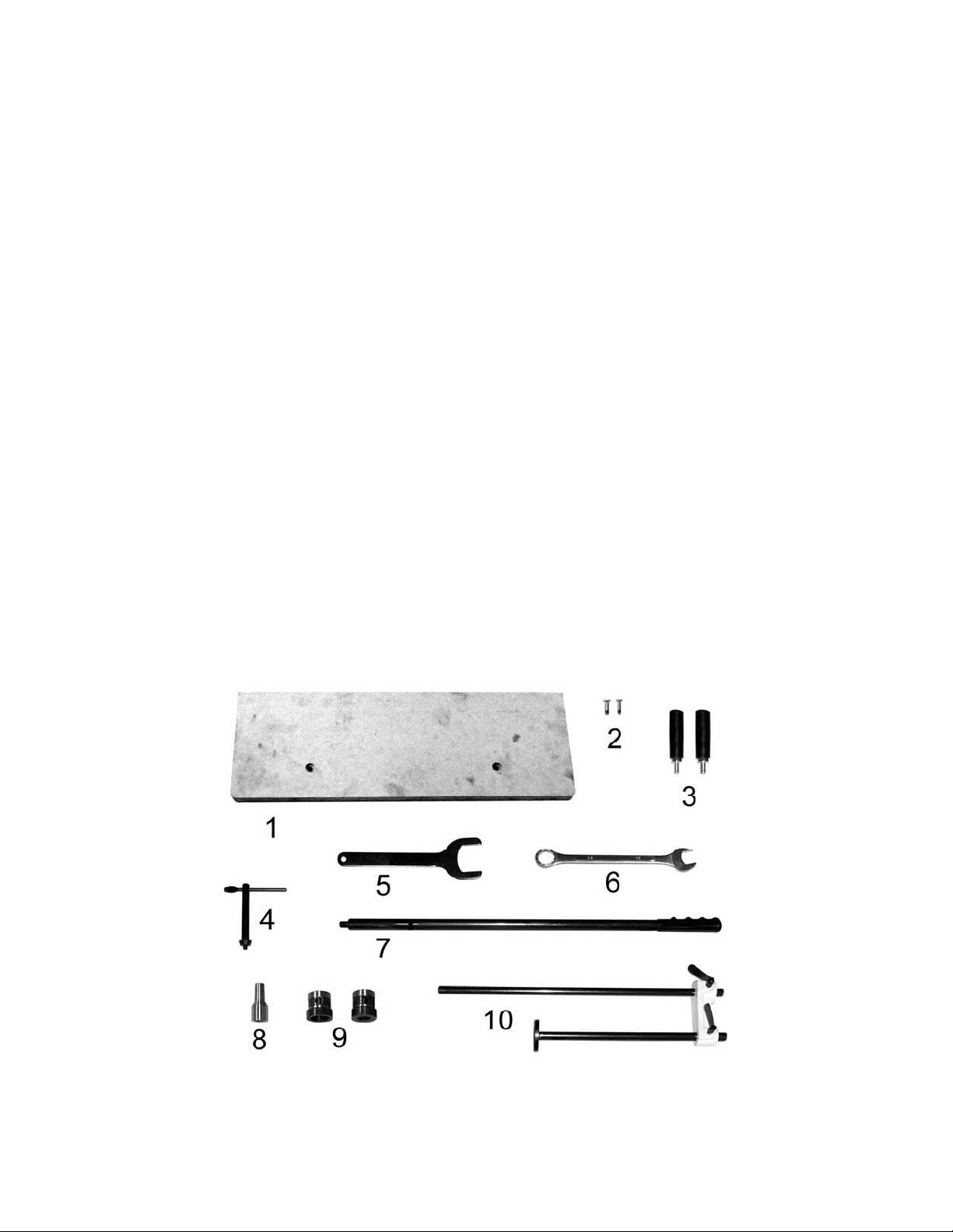
Contents of the Mortiser Carton
1 ea – Mortiser (not shown)
1. 1 ea – Wooden Table
2. 2 ea – M6 x 20 Phillips Head Screws
3. 2 ea – Handwheel Handles
4. 1 ea – Chuck Key
5. 1 ea – Chuck Removal Wrench
6. 1 ea – 23mm Box Wrench
7. 1 ea – Operating Handl e
8. 1ea – Chuck Extension A daptor
9. 2 ea – Chisel Bushings (3/4" , 1-1/8")
Note: The Mortiser also comes with a 5/8"
bushing already installed.
10. 1 Work Stop Assembly
Contents of the Stand Carton
1 Stand (not shown)
1 Hardware package – (4) M8 x 45 Hex Cap
Screws, (4) M8 Lock Washers (not sho wn)
Contents of the Mortis er Car ton
Figure 1
7
Page 8

Electrical Connections
A separate electrical circuit should be used for your machines. This circuit should not be less than #12 wire and
should be protected with a 20 Amp time lag fuse. If an extension cord is used, use only 3-wire extension cords which
have 3-prong grounding type plugs and matching receptacle, which will accept the machine’s plug. Before connecting
the machine to the power line, make sure the switch is in the Off position and be sure that the electric current is of the
same characteristics as indicated on the machine. All line connections should make good contact. Running on low
voltage will d amage the machi ne.
Grounding Instructions
Electrical connections must be made by a qualified electrician in compliance with all
relevant codes. This machine must be properly grounded to help prevent electrical shock and possible fatal
injury.
1. All grounded, cord-connected tools:
In the event of a malfunction or breakdown, grounding provides a path of least resistance for electric current to
reduce the risk of electric shock. This tool is equipped with an electric cord having an equipment-grounding conductor
and a grounding plug. The plug must be plugged into a matching outlet that is properly installed and grounded in
accordance with all local codes and ordinances.
Do not modify the plug provided - if it will not fit the outlet, have the proper outlet installed by a qualified electrician.
Improper connection of the equipment-grounding conductor can result in a risk of electric shock. The conductor with
insulation having an outer surface that is green with or without yellow stripes is the equipment-grounding conductor. If
repair or replacement of the electric cord or plug is necessary, do not connect the equipment-grounding conductor to
a live terminal.
Check with a qualified electrician or service personnel if the grounding instructions are not completely understood, or
if in doubt as to whether the tool is properly grounded.
Use only 3-wire extension cords that have 3-prong grounding plugs and 3 pole receptacles that accept the tool's plug.
Repair or replace damaged or worn cord immediately.
2. Grounded, cord-connected tools intended for use on a supply circuit having a nominal rating less than
150 volts:
This tool is intended for use on a circuit that has an outlet that looks like the one illustrated in Sketch A in Figure 1.
The tool has a grounding plug that looks like the plug illustrated in Sketch A in Figure 1. A temporary adapter, which
looks like the adapter illustrated in Sketch B and C, may be used to connect this plug to a 2 pole receptacle as shown
in Sketch C if a properly grounded outlet is not available. The temporary adapter should be used only until a properly
grounded outlet can be installed by a qualified electrician. This adapter is not permitted in Canada. The gr een-
colored rigid ear, lug, and the like, extending from the adapter must be connected to a permanent ground such as a
properly grounded outlet box.
Figure 2
8
Page 9

3. Grounded, cord- connected tools intended for use on a supply circuit having a nominal rating between
A
150 - 250 volts, inclusive.
This tool is intended for use on a circuit that has an outlet that looks like the one illustrated in Sketch D in Figure 1.
The tool has a grounding plug that looks like the plug illustrated in Sketch D in Figure 1. Make sure the tool is
connected to an outlet having the same configuration as the plug. No adapter is available or should be used with this
tool. If the tool must be reconnected for use on a different type of electric circuit, the reconnection should be made by
qualified service personnel; and after reconnection, the tool should comply with all local codes and ordinances.
4. Permanently connected tools:
This tool should be connected to a grounded metal permanent wiring system; or to a system having an equipmentgrounding conductor.
Converting from 115 to 230 Volt
Remove the cover of the push button switch and consult the diagram inside the cover. This diagram is also shown in
Figures 3 and 4. (The diagram inside the cover takes precedence – always check it first ).
Disconnect the machine from the power source.
This mortiser is supplied with four leads that are connected for 115V operation, as shown in Figure 3. Reconnect
these four leads for 230V operation, as shown in Figure 4.
The 115V attachment plug (shown in A, Figure 2) must be replaced with a UL/CSA listed plug suitable for 230V
operation (shown in D, Figure 2). The mortiser must comply with all local and national codes after the 230 volt plug is
installed.
Important: In all cases (115 or 230 volts), make certain the receptacle in question is properly grounded. If
you are not sure, have a registered electrician check the receptacle.
Figure 3 Figure 4
Extens ion Cords
If an extension cord is necessary, make sure the cord rating is suitable for the amperage listed on the machine’s
motor plate. An undersize cord will cause a drop in line voltage resulting in loss of power and overheating. Use the
chart in Figure 5 as a general guide in choosing the correct size extension cord for the Bandsaw. If in doubt, use the
next heavier gauge. The smaller the gauge number, the heavier the cord.
Recommended Minimum Gauge (AWG) of Extension Cords
Volts Total Length of Cord in Feet
115 V 25 ft. 50 ft. 100 ft. 150 ft.
230 V 50 ft. 100 ft. 200 ft. 300 ft.
Ampere Rating
< 6 18 16 16 14
6 to 10 18 16 14 12
10 to 12 16 16 14 12
12 to 16 14 12
Figure 5
WG
Not recommended Not recommended
9
Page 10

Assembly
Do not con nect t he mach ine
to power source until completely
assembled. Read and und erstand the entire
manual.
Securing Machine to Stand
The mortiser should be secured to the stand
with four M 8 x 45 hex c ap screws and M8 lock
washers (provided) using the holes in the bas e.
Make sure there i s enough room on each side
of the mortiser for the size stock you plan to
use.
Wooden Table
Referring to Fi gur e 6:
1. Place the wooden table (A) in position on
the slide (B).
2. Secure with two Phillips head screws
provided (C).
Operating Handle
Referring to Fi gur e 7:
1. Fasten operating handle (A) to the hub (B)
and tighten with a 14mm open-end wrench.
2. Raise mortising machine head to the up
position by moving the operating handle
(A) up.
Figure 6
Note: The handle assembly is spring-loaded
and can be repositioned by pulling out the
hub (B) and repositioning it on the pinion
shaft (C).
Figure 7
10
Page 11

Installing Chisel and Bit
T
S
Referring to Figure8:
1. Loosen the lock screw.
2. Insert the chisel bushing i nto the head with
the hole f acing forward to line up wit h the
lock screw. Screw in the lock screw just
enough so the screw ext ends into the hole
of the bushing, holding it in place.
3. Push the chisel up through the bushing,
bringing it to rest against the shoulder of
the bushing. Then lower the chisel
approxim ately 1/16" to 3/ 16", depending on
the type of wood being worked.
Note: Set the slot in the side of the chisel to the
left or right, if the workpiece is to be moved
laterally and front or back if it is to be moved
from front to back. Mov e the workpiece so that
the slot i n the chisel i s releasing chips int o the
already cut part of the workpiece (see
Figure 19).
4. Tighten the lock screw to hol d the chisel in
place.
5. Push the bit up through the chi sel opening
as far as it will go. Lock t he drill bit in pl ace
with the chuck key.
6. Loosen the lock screw and pu sh the chisel
up against the bushing, then tighten the
lock screw. This should prov ide the proper
distance between the points of the chisel
and the bit.
Note: This would be a good plac e to make sure
that the chi sel is paral lel to t he workpiece. See
the Chisel Parallel t o Workpiece section.
Figure 8
Work Stop
The work stop c an be m ount ed to ei t her end of
the table through the holes in the back of the
table, as shown in F igure 9. It is tightened into
place by means of thumbscrews.
HUMBSCREWS
Figure 9
HOLE
11
Page 12

Operating Controls
Start/Stop Switch
Referring to Figure 10: The S tart/Stop Switch is
located to the left of the motor on the side of
the morti ser. To turn the m ortiser on pre ss the
green START (A) butt on. To stop the morti ser,
push the red STOP (B) button.
Figure 10
On-Off Switch Padlock
The push button switch of the Mortiser will
accept a safety padlock (not included). To
safeguard your machine from unauthorized
operation and accidental starting by young
children, the use of a padlock is highly
recommended – see Figur e 11.
Figure 11
12
Page 13

Adjustments
90° Chisel to Worktable Calibration
Referring to Fi gur e 12:
Place a square (E) so it rests against the
worktable (B) and chisel (A). If the chisel to
table angle is 90°, no cali br ation is necessary.
If calibrati on is required:
1. Loosen the bolt (C) that allows the tilting
base to pivot.
T he tilting base is heavy. If
raised, take extra precaution not to let it
drop on hands or fingers. In ju ry can resu lt.
2. Adjust the adjustment screws (F) until the
chisel to table angle is 90°. Calibration is
then complete.
3. Retighten the bolt (C).
Upon completion, make sure that the pointer
points to 0°. Calibr ate if necessary.
Chuck Extension Adaptor
The provided Chuck Extension Adaptor (C) is
intended to lower the chuck for use with
after-market chisels (chisels other than the
POWERMATIC brand) that may require a
spacer due to varyi ng lengths in shanks.
Figure 12
To install the adaptor, first remove the chisel
and bit (see the Installing Chisel and Bit
section). Then, referring to Figure 13:
1. Loosen the lock screw (E) enough to
remove the chisel bus hing (F).
2. Remove the chisel bushing (F). This is
necessary to provide enough clearance
when installing the chuck and extension
adaptor.
3. Unscrew the chuck release nut (A)
countercl ockwise with the wrench prov ided
to force the chuck (D) off the shaft (B).
It may be necessary to hold the shaft
stationary whil e turning the nut. This can
be done by insert ing the chuck key handle
into the hole i n the chuck and all owing it to
wedge against the edge of the headstock.
4. When the chuck is off, return the chuck
release nut (A) to its original posi tion on the
shaft (B).
5. Push the adaptor (C) into the chuck (D).
Then push this assembly onto the motor
shaft (B).
Figure 13
13
Page 14

6. Reinstall the chisel bushing (F) and secure
B
it loosely with the lock screw (E).
7. Reinstall the chisel and bit (refer to the
Installing Chisel and Bit section).
Depth Stop Rod Adjustment
Referring to Fi gur e 14:
A depth stop rod (A) is provided to limit the
depth of the chisel . T o adjust:
1. Loosen lock lever (B) and lower the depth
stop rod (A) until it comes to rest on top of
the column stop (C).
2. With the operating handle (see Figure 2)
lower the head (E) until the chisel (D) is at
the desired depth.
3. The depth stop rod (A) should sti ll be
resting on top of the c olum n stop (C).
4. Tighten the lock lever (B).
Table Position
The 719T Mortiser is equipped with two
handwheels for t able (E, Fi g. 15) positi oning. I n
addition, the table can be tilted up to 35° for
angle mortising.
Forward/Backward Table Movement
1. Loosen the w ing screw on the right side of
the middle base under the table.
2. Turn the handwheel (A, Fig. 15) to move
the table the forward or backward.
3. Tighten the wing screw.
A
C
E
D
Figure 14
Lateral Table Movement
1. Loosen the wing scr ew loc ated on the bac k
of the middle base located near the
column.
2. Turn the handwheel (B, Fig. 15) to move
the table to the right or left.
3. Tighten the wing screw.
Table Tilt Control
The t ilt t able is h eavy. Wh en
raised, take extra precaution not to let it
drop on hands or fingers. In ju ry can resu lt.
1. Loosen bolt (C, Fig. 15) with the 23mm
wrench prov ided.
2. Pivot the table t o adjust the angl e up to 35°
using the scale (D) on the t ilt bracket as a
guide.
3. Tighten the bolt (C).
Figure 15
14
Page 15

Chisel Parallel to Workpiece
A
Referring to Fi gur e 16:
The chisel can be adjusted parallel to the
workpiece as follows:
1. With the left handwheel (A), move the table
back far enough to i nsert t he workpiece (B)
between the chisel (D) and fence.
2. Loosen the lock screw (C). This will allow
the chisel to rotate.
3. Bring the table f orward with the handwheel
(A) until the workpiece (B) rests against the
back surface of the chisel (D), but do not
force.
Further adjust t he c hisel by hand if needed.
4. Tighten the lock screw (C).
Operation
1. Set the depth stop (A, Fig. 17) to the
required depth of cut. Refer to the Depth
Stop Rod Adjustment sect ion.
Figure 16
5. Place workpiec e on table (C, Fig. 18) and
clamp it wit h the vi se (A, Fig. 18). Use the
left handwheel (D, Fig. 18) to move table
forward or backwar d to suit the posit ion of
the mortise on the workpi ec e.
6. Adjust the table stops according to the
length of cut required, then tighten the
thumbscrews ( B, Fig. 18) .
Before turning the machine
on, verify that the chuck key is not in the
chuck.
7. Turn on the machine and feed the chisel
and bit steadily into workpiece by pulling
down the operating handle.
Note: The rat e of feed must be fast enough t o
prevent bur ning at the tip of the bit, but not so
fast as to cause the machi ne to slow or stall.
The different rates of feed for different woods
must be learned thr ough ex per ience.
8. After t he fir st cut, the workpiece is moved
along with the r ight handwheel (E. Fig. 18)
for each successive cut. The direction of
movement must allow the chips to clear
freely. Mov e the workpiece so that the slot
in the chisel is releasing chips into the
already cut part of the workpiece
(Figure 19).
A
B
C
D
Figure 17
F
C
B
D
Figure 18
E
15
Page 16

Do not have the chisel slot
against t he blind end of the mortise, as th e
chips will not be able to clear the chisel.
This can cause overheating and possible
breakage of chi sel o r bit.
When cutting deep mortises, make the cut in
several stages of approximately 1" each, to
allow chips to c lear . T o prev ent br eakout at t he
back of the workpiece when cutting through
mortises, use a piece of scrap m aterial under
the workpiece as support.
Maintenance
Before any intervention on
the machine, disconnect it from the
electrical su pply by pulling out th e plug or
switching off the main switch! Failure to
comply may cause seriou s injury.
General
A coat of paste wax applied to the table and
column will hel p to keep the surfaces clean.
If the power cord is worn, cut, or damaged in
any way, have it repl ac ed immediately.
The Mortiser requi res only minor maintenance,
such as cleaning and lubrication and routine
adjustment and sharpening of the chisel and
bit.
Dust the machi ne down after each use and, as
necessary, use light applications of oil or
grease to lubri c ate linkages, moving parts, et c.
Sharpening Chisel and Bit
The chisel and bit should be kept sharp f or best
performance. Blunt edges will give inaccurate
mortises and can lead to overheating and
breakage to chisel or bit. If chisel and bit are
badly worn and become difficult to sharpen,
they should be repl ac ed.
Figure 19
Bit
Sharpen the bit by using a small, smooth file,
following the origina l shape of the bit. File the
inside edge of the spur, the sides of the brad
point, and t he cutting edge i nwards toward the
flute of the bit (Figur e 20) .
Do not fil e t he outside ed ge of t he spur, a s this
will affect the diameter of the bit.
Figure 20
16
Page 17

Chisel
Sharpen the chi sel with a mortise chisel cutter
with the correct size pilot. (Pilot size will differ
depending on the size of your chisel). Two or
three turns of the cutter in a carpent er's brace
chuck should be enou gh to sharpen the chi sel,
as shown in Figure 21.
Use a small, triangular, smooth file to relieve
the inner corners of the chisel (Figure 22).
Remove any burrs from the outside of the
chisel with a fine oilstone.
Lubrication
All of the ball bearings are packed with grease
at the factory. They require no further
lubrication.
Periodic ally grease the gears, racks, and table
pivot points wit h a #2 tube grease.
Periodic ally clean and oil any ex posed machine
surfaces, such as: dove-tail ways and slides,
and table surface.
Storage
If the mortiser will be stored for an extended
period, use the depth stop to help secure the
head in position; this will relieve stress upon
the hydraulic cylinder.
Optional Accessories
1791091 Premium Morti se Chi sel & Bit 1/ 4"
1791092 Premium Morti se Chi sel & Bit 5/ 16"
1791093 Premium Morti se Chi sel & Bit 3/ 8"
1791094 Premium Morti se Chi sel & Bit 1/ 2"
1791095 Premium Morti se Chi sel & Bit 3/ 4"
1791096 Premium Morti se Chi sel & Bit, set of 4 (1/4”, 5/16”, 3/8”, 1/2”)
Figure 21
Figure 22
Replacement Parts
Replacement par ts are li sted on the f ollowing page s. To order parts or reac h our servi ce depar tm ent, call
1-800-274-6848, Monday through Friday (see our website for business hours, www.powermatic.com).
Having the Model Number and Serial Number of your mac hine available when you cal l will allow us to
serve you quickly and accurately.
17
Page 18

719T Mortiser Assembly
18
Page 19

719T Mortiser Parts List
Index No. Part No. Description Size Qty
................. 2474002T ................719T Mortiser Assy (Index No. 1 thru 120) ........................................... 1
1 ............... 719T-101 .................Fixed Base ............................................................................................ 1
2 ............... 6294125...................Base, Middle ......................................................................................... 1
3 ............... 6294126...................Gib ........................................................................................................ 1
4 ............... TS-1523061 .............Socket Set Screw ...............................................M6×20 ........................ 3
5 ............... TS-1540041 .............Hex Nut ..............................................................M6 .............................. 9
6 ............... 6294129...................Lead Scr ew ........................................................................................... 1
7 ............... TS-1523031 .............Socket Set Screw ...............................................M6×10 ........................ 4
8 ............... 6294131...................Handwheel ............................................................................................ 1
9 ............... 6294132...................Shaft ..................................................................................................... 1
10 ............. 6294133...................Gear ...................................................................................................... 1
11 ............. 6294134...................C-Clip .................................................................................................... 1
12 ............. 6294135...................Handwheel ............................................................................................ 1
13 ............. BB-6002ZZ ..............Bearing...............................................................6002ZZ....................... 2
14 ............. 6294137...................C-Clip .................................................................................................... 2
15 ............. TS-1503041 .............Socket Head Cap Screw .....................................M6×16 ........................ 2
16 ............. 6294139...................Stop Block ............................................................................................. 1
17 ............. 6294140...................Gib ........................................................................................................ 1
18 ............. 6294141...................Main Table ............................................................................................ 1
19 ............. TS-1523011 .............Socket Set Screw ...............................................M6×6 .......................... 4
20 ............. 6294143...................Setting Collar ......................................................................................... 2
21 ............. 6294144...................Setting Rod ........................................................................................... 1
22 ............. 6294145...................Wing Screw ........................................................M6×16 ........................ 3
23 ............. 6294146...................Rack ...................................................................................................... 1
24 ............. TS-
25 ............. 6294148...................Rear Length Setting Rod ....................................................................... 1
26 ............. 6294149...................Length Setting Bl oc k .............................................................................. 1
27 ............. 6294150...................Front Length Setting Rod ....................................................................... 1
28 ............. 6294151...................Wooden Worktable ................................................................................ 1
29 ............. TS-2286201 .............Phillips Flat Head Machine Screw .......................M6×20 ........................ 2
30 ............. 719T-130 .................C olumn.................................................................................................. 1
31 ............. 6294154...................Wave Washer ........................................................................................ 2
32 ............. 6294155...................Gib ........................................................................................................ 1
33 ............. 6294156...................Headstock ............................................................................................. 1
34 ............. 719T-134 .................Rack ...................................................................................................... 1
35 ............. TS-1503031 .............Socket Head Cap Screw .....................................M6×12 ........................ 4
36 ............. 6294159...................Left Side Cover ...................................................................................... 1
37 ............. 6294160...................Right Side Cover ................................................................................... 1
38 ............. TS-1533042 .............Phillips Pan Head Machine Screw ......................M5×12 ........................ 4
39 ............. 6294162...................Gear ...................................................................................................... 1
40 ............. 6294163...................Collar .................................................................................................... 1
41 ............. 6294164...................Gear Shaft ............................................................................................. 1
42 ............. 6294165...................Handle Hub ........................................................................................... 1
43 ............. 6294166...................Spring .................................................................................................... 1
44 ............. 6294167...................Washer.................................................................................................. 1
45 ............. TS-1514021 .............Socket Head Flat Screw .....................................M6×16 ........................ 2
46 ............. 6294169...................Handle................................................................................................... 1
47 ............. 6294170...................Handle Grip ........................................................................................... 1
48 ............. 6294171...................Chuck ................................................................1/2” & Key .................. 1
49 ............. 6294172...................Motor, 1HP, 1PH, 115/230V................................................................... 1
50 ............. 6294173...................Switch Box ............................................................................................ 1
51 ............. TS-081C052 ............Phillips Pan Head Machine Screw ......................#10-24 × 3/4 ............... 2
52 ............. 6294175...................Switch ................................................................................................... 1
53 ............ TS-0749042 .............Phillips Pan Head Tapping Screw .......................#8 × 5/8 ..................... 2
54 ............. TS-1503051 .............Socket Head Cap Screw .....................................M6×20 ........................ 3
55 ............. 6294178...................Upper Cylinder Fitting ............................................................................ 1
1523071 .............Socket Set Screw ...............................................M6×25 ........................ 6
19
Page 20

Index No. Part No. Description Size Qty
56 ............. 719T-156 .................Hydraulic Cylinder ................................................................................. 1
57 ............. 6294180...................C-Clip .................................................................................................... 2
58 ............. 6294181...................Depth Setting Block ............................................................................... 1
59 ............. 719T-159 .................Depth Setting Rod ................................................................................. 1
60 ............. 6294183...................Universal Handle ................................................................................... 1
61 ............. TS-1505041 .............Socket Head Cap Screw .....................................M10×30 ...................... 4
62 ............. TS-2361101 .............Lock Washer ......................................................M10 ............................ 8
63 ............. 6294186...................Clamping J a w ........................................................................................ 1
64 ............. 6294187...................Clamping B lock ..................................................................................... 1
65 ............. 6294188...................Rapid Nut .............................................................................................. 1
66 ............ 6294189...................Friction Toe ........................................................................................... 1
67 ............. 6294190...................Spring .................................................................................................... 1
68 ............. 6294191...................Rivet ...................................................................................................... 1
69 ............. 6294192...................Locking Screw ....................................................................................... 1
70 ............. 6294193...................Stop Disc ............................................................................................... 1
71 ............. TS-1504051 .............Socket Head Cap Screw .....................................M8×25 ........................ 2
72 ............. TS-1550061 .............Flat Washe r ........................................................M8 .............................. 2
73 ............. TS-1504061 .............Socket Head Cap Screw .....................................M8×30 ........................ 2
74 ............. 6294197...................Chisel Locking Screw ............................................................................ 1
75 ............. 6294198...................Bushing ..............................................................1-1/8” ......................... 1
75A .......... 6294221...................Bushing ..............................................................3/4”............................. 1
75B .......... 6294222...................Bushing ..............................................................5/8”............................. 1
76 ............. 6294199...................Wheel Handle ........................................................................................ 2
77 ............. 6294200...................Collar .................................................................................................... 1
78 ............. 6294201...................E-Clip .................................................................................................... 2
79 ............ 6294202...................Back Cover ............................................................................................ 1
80 ............. TS-1532032
81 ............. 6294204...................Chuck Key ............................................................................................. 1
82 ............. 6294205...................Chuck Key Holder.................................................................................. 1
83 ............. TS-2361051 .............Lock Washer ......................................................M5 .............................. 1
84 ............. TS-1502011 .............Socket Head Cap Screw .....................................M5 × 8 ........................ 1
85 ............. 6294208...................Chuck Release Nut ................................................................................ 1
86 ............. 6294209...................Wave Washer ........................................................................................ 1
87 ............. 6294240...................Cylinder Holder ...................................................................................... 2
88 ............. 6294211...................Wrench (Chuck Removal) ...................................................................... 1
89 ............. 6294212...................Lower Cylinder Fitting ............................................................................ 1
90 ............. 6294213...................Wing Screw ........................................................M6 × 8 ........................ 2
91 ............. 6294214...................Roll Pin.................................................................................................. 1
92 ............. 6294215...................Key.....................................................................5 × 5 × 10 ................... 1
93 ............. 6294216...................Key.....................................................................5 × 5 × 12 ................... 1
94 ............. 6294217...................Power Cord ........................................................................................... 1
95 ............. 6294223...................Handle Protect or ................................................................................... 1
96 ............. 3005069...................Chuck Extension Adaptor ...................................................................... 1
97 ............. JWP15-065 ..............Wing Screw ........................................................M6×25 ........................ 2
98 ............. TS-0267051 .............Socket Set Screw ...............................................1/4-20 ×1/2 ................. 2
99 ............. TS-2361081 .............Lock Washer ......................................................M8 .............................. 2
100 ........... TS-2360121 .............Flat Washer ........................................................M12 ............................ 1
101 ........... TS-2361061 .............Lock Was h e r ......................................................M6 .............................. 3
102 ........... 6294243...................Roll Pin...............................................................M6 × 16 ...................... 1
103 ........... 6294244...................Cord Strain Relief .................................................................................. 1
104 ........... 719T-1104 ...............Pin ......................................................................................................... 1
105 ........... 719T-1105 ...............Poin ter................................................................................................... 1
106 ........... TS-1550041 .............Flat Washe r ........................................................M6 .............................. 1
107 ........... TS-1534032 .............Phillips Pan Head Machine Screw ......................M6 x 10 ...................... 1
108 ........... 719T-1108 ...............Tilt ing B ra c ke t........................................................................................ 1
109 ........... TS-155010 ...............Flat Washer ........................................................M16 ............................ 1
110 ........... 719T-1110 ...............Sha ft ..................................................................................................... 1
111 ........... 719T-1111 ...............Square Nut ............................................................................................ 1
112 ........... TS-1490051 .............Hex Cap Scr e w ..................................................M8 x 30 ...................... 2
.............Phillips Pan Head Machine Screw ......................M4 × 10 ...................... 6
20
Page 21

Index No. Part No. Description Size Qty
113 ........... TS-1540061 .............Hex Nut ..............................................................M8 .............................. 2
114 ........... TS-1491021 .............Hex Cap Scr e w ..................................................M10 x 20 .................... 4
115 ........... 719T-1115 ...............Tilt ing B ra c ke t........................................................................................ 1
116 ........... TS-2342161 .............Hex Nut, Nylon Lock ...........................................M16 ............................ 2
117 ........... 719T-1117 ...............Wa ve Washe r ........................................................................................ 2
118 ........... 719T-1118 ...............Bolt ........................................................................................................ 2
119 ........... 719T-1119 ...............Tilt ing B a se ........................................................................................... 1
120 ........... 719T-1120 ...............Box Wren ch ........................................................23mm ......................... 1
21
Page 22

719T Mortiser Stand Parts List
Index No. Part No. Description Size Qty
................. 6294235T ................Stand Assembly (Items 1 thru 8) ............................................................ 1
1 ............... 719T-201 .................Stand .................................................................................................... 1
2 ............... 719T-202 .................Shelf Cushion ........................................................................................ 1
................. 6294236...................Door Assembly (Index No. 3 thru 6) ....................................................... 1
3 ............... 6294226...................Door ...................................................................................................... 1
4 ............... 6294227...................Pin......................................................................................................... 2
5 ............... 6294228...................Door Latch............................................................................................. 1
6 ............... TS-2171012 .............Phillips Pan Head Machine Screw ......................M4 x 6 ........................ 2
7 ............... TS-2361081 .............Lock Was h e r ......................................................M8 .............................. 4
8 ............... TS-1490081 .............Hex Cap Screw ..................................................M8 × 45 ...................... 4
719T Mortiser Stand Assembly
22
Page 23

Optional Accessories
Index No. Part No. Description
................. 1791096...................Set of 4 Mortise Chisels and Bits (1/4”, 5/16”, 3/8” and 1/2”) .....................
................. 1791091...................Premium Mortise Chisel and Bit, 1/4” .......................................................
................. 1791092...................Premium Mortise Chisel and Bit, 5/16” .....................................................
................. 1791093...................Premium Mortise Chisel and Bit, 3/8” .......................................................
................. 1791094...................Premium Mortise Chisel and Bit, 1/2” .......................................................
................. 1791095...................Premium Mortise Chisel and Bit, 3/4” .......................................................
................. 6294245...................Chuck & Key, 1/2" ...................................................................................
................. 6294198...................Drill Bushing, 1-1/8" .................................................................................
................. 6294221...................Drill Bushing, 3/4" ....................................................................................
................. 6294222...................Drill Bushing, 5/8" ....................................................................................
................. 6294232...................Chuck Extension Adaptor Kit (Includes index # 1 thru 3) ..........................
1 ............... 6294210...................Drill Adaptor Shaft ...................................................................................
2 ............... 6294208...................Chuck Release Nut ..................................................................................
3 ............... 6294209...................Wa ve Washer ..........................................................................................
Powermatic
®
719T Mortiser (1791264K) S pecifications
in conjunction wit h Pow ermat ic’s Premium Chisel and Bit Sets
23
Page 24

Dimensions for 719T with premium chisels mounted
(Chisels and bit s purchased separately)
Powermatic 719T Mortiser and Chisel Dimensions
A Total Chisel Length (installed) 3-21/32” 3-7/8 3-7/8” 3-7/8” 5-13/16”
B Useful Chisel Plunge 1-13/16” 2-1/8” 2-3/4” 3-5/32” 5”
C Maximum Chisel Centerline to Fence 4-5/8” 4-5/8” 4-5/8” 4-5/8” 4-5/8”
D Maximum Working Clearance* 10” 9-7/8” 9-7/8” 9-7/8” 7-5/8”
E Maximum Total Clearance* 13-3/4” 13-3/4” 13-3/4” 13-3/4” 13-3/4”
F Maximum Clamping Capacity 5-7/8” 5-7/8” 5-7/8” 5-7/8” 5-7/8”
Maximum X-Axis Table Travel 16-1/2” 16-1/2” 16-1/2” 16-1/2” 16-1/2”
Maximum Y-Axis Table Travel 5” 5” 5” 5” 5”
Bushing size used 3/4” 3/4” 3/4” 3/4” 3/4”
* measured with provided wood table installed; add 11/16” to each figure if wood table is removed.
1791091
1/4”
chisel
1791092
5/16”
chisel
1791093
3/8”
chisel
1791094
1/2”
chisel
1791095
3/4”
chisel
427 New Sanford Road
LaVergne, Tennessee 37086
Phone: 800-274-6848
www.powermatic.com
24
 Loading...