

Page 1
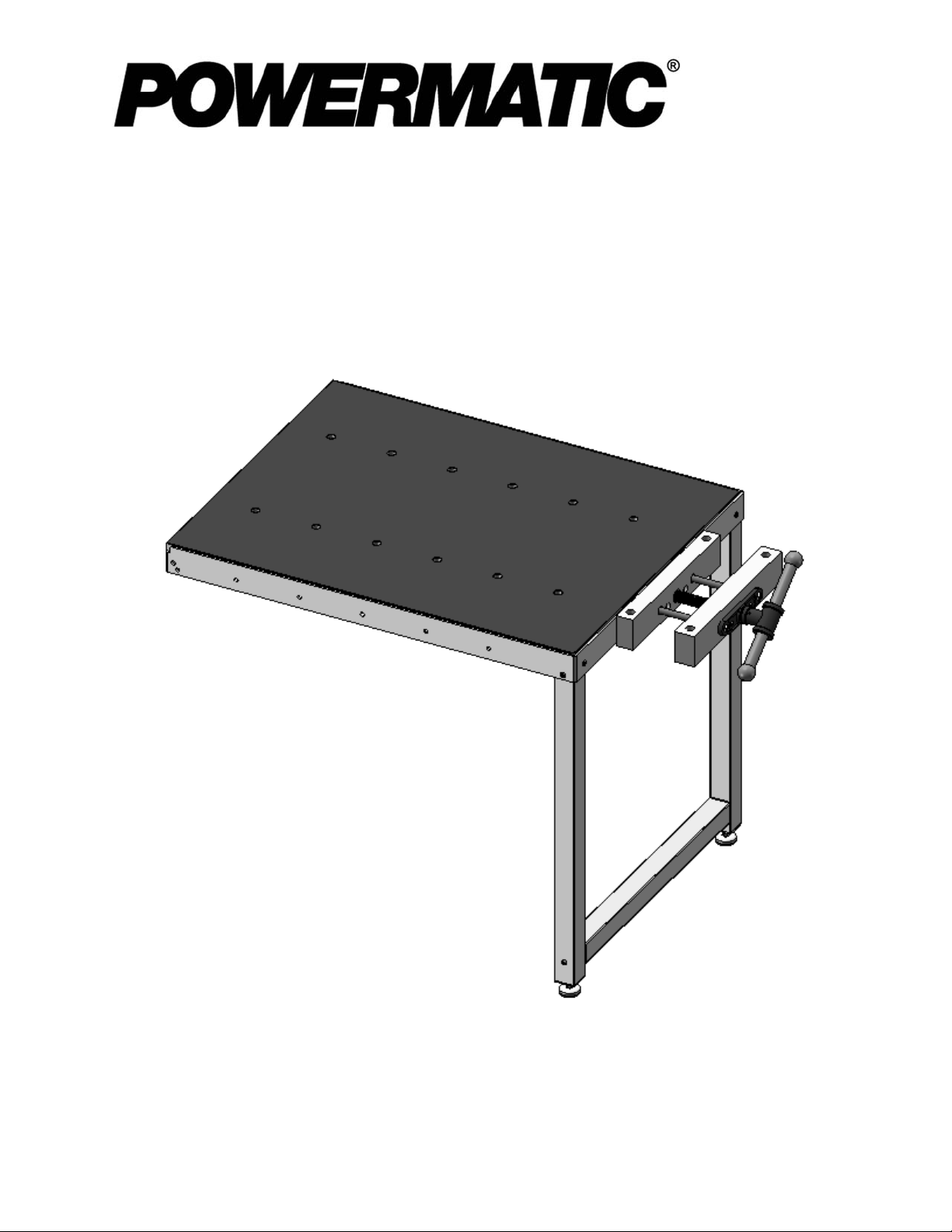
Instructions for 6827045B Accessory Workbenc h Table
The Powermatic Workbench Table is an optional accessory intended for use with the Powermatic
PM2000 Table S aw. It requires minor assembl y and will bolt to the rails of the table saw with no drilling
needed.
Read carefully the instructions on the following pages for assembly and adjustment pr oc edur es.
Powermatic
427 New Sanford Road
LaVergne, Tennessee 37086 Part No. M-6827045B
Ph.: 800-274-6848 Revision B 02/2014
www.powermatic.com Copyright © 2014 Powerm atic
Page 2

Warranty and Service
Powermatic warrants every product it sells against manufacturers’ defects. If one of our tools needs service or repair,
please contact Technical Service by calling 1-800-274-6846, 8AM to 5PM CST, Monday through Friday.
Warranty Period
The general warranty lasts for the time period specified in the literature included with your product or on the official
Powermatic branded website.
• Powermatic products carry a limited warranty which varies in duration based upon the product. (See chart
below)
• Accessories carry a limited warranty of one year from the date of receipt.
• Consumable items are defined as expendable parts or accessories expected to become inoperable within a
reasonable amount of use and are covered by a 90 day limited warranty against manufacturer’s defects.
Who is Covered
This warranty covers only the initial purchaser of the product from the date of delivery.
What is Co vered
This warranty covers any defects in workmanship or materials subject to the limitations stated below. This warranty
does not cover failures due directly or indirectly to misuse, abuse, negligence or accidents, normal wear-and-tear,
improper repair, alterations or lack of maintenance.
Warranty Limitations
Woodworking products with a Five Year Warranty that are used for commercial or industrial purposes default to a
Two Year Warranty. Please contact Technical Service at 1-800-274-6846 for further clarification.
How to Get Technical Support
Please contact Technical Service by calling 1-800-274-6846. Please note that you will be asked to provide proof
of initia l p u rch a s e whe n calling. If a product requires further inspection, the Technical Service representative will
explain and assist with any additional action needed. Powermatic has Authorized Service Centers located throughout
the United States. For the name of an Authorized Service Center in your area call 1-800-274-6846 or use the Service
Center Locator on the Powermatic website.
More Informatio n
Powermatic is constantly adding new products. For complete, up-to-date product information, check with your local
distributor or visit the Powermatic website.
How S tate Law Applies
This warranty gives you specific legal rights, subject to applicable state law.
Limitations on This Warranty
POWERMATIC LIMITS ALL IMPLIED WARRANTIES TO THE PERIOD OF THE LIMITED WARRANTY FOR EACH
PRODUCT. EXCEPT AS STATED HEREIN, ANY IMPLIED WARRANTIES OF MERCHANTABILITY AND FITNESS
FOR A PARTICULAR PURPOSE ARE EXCLUDED. SOME STATES DO NOT ALLOW LIMITATIONS ON HOW
LONG AN IMPLIED WARRANTY LASTS, SO THE ABOVE LIMITATION MAY NOT APPLY TO YOU.
POWERMATIC SHALL IN NO EVENT BE LIABLE FOR DEATH, INJURI ES TO PERSONS OR PROPERTY, OR
FOR INCIDENTAL, CONTINGENT, SPECIAL, OR CONSEQUENTIAL DAMAGES ARISING FROM THE USE OF
OUR PRODUCTS. SOME STATES DO NOT ALLOW THE EXCLUSION OR LIMITATION OF INCI DENT AL OR
CONSEQUENTIAL DAMAGES, SO THE ABOVE LIMITATION OR EXCLUSION MAY NOT APPLY TO YOU.
Powermatic sells through distributors only. The specifications listed in Powermatic printed materials and on the official
Powermatic website are given as general information and are not binding. Powermatic reserves the right to effect at
any time, without prior notice, those alterations to parts, fittings, and accessory equipment which they may deem
necessary for any reason whatsoever.
Product Listing with Warranty Period
90 Days – Parts; Consumable items
1 Year – Motors, Machine Accessories
2 Year – Woodworking Machinery used for industrial or commercial purposes
5 Year – W oodworking Machinery
NOTE: Powermatic is a division of JPW Industries, Inc. References in this document to Powermatic also apply to
JPW Industries, Inc., or any of its successors in interest to the Powermatic brand.
2
Page 3
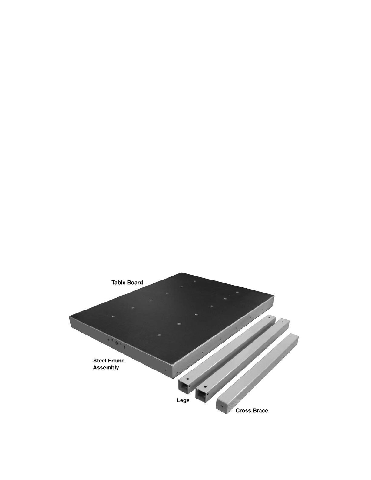
Unpacking
Compare cont ents of shipping carton against the li st and illustrations below and on page 3. Report any
damage immediat ely to your distributor. If any parts are missing, contact Powerm atic at 800-274- 6848.
Remove all l oose items f rom the workbench f rame, such as the v ise assembly, vise faces, vi se handle,
legs, cross brace, and hardware package.
Contents of Carton:
Refer to Figures 1 t hr ough 5:
9 Part No. Description Qty
6827045B-SFA............. Steel Frame Assembly ...................................... 1
6827045B-2 ................. Table Board ...................................................... 1
6827045B-3 ................. Leg ................................................................... 2
6827045B-4 ................. Cross Brace ...................................................... 1
6827045B-5 ................. Adjustable Foot ................................................. 2
6827045B-6 ................. Vise Face-1 ...................................................... 1
6827045B-7 ................. Vise Face-2 ...................................................... 1
6827045B-VA ............... Vise Assembly .................................................. 1
6827045B-12 ............... Wood Screw, M5x30L ....................................... 2
6827045B-15 ............... Vise Handle Shaft ............................................. 1
6827045B-16 ............... Vise Handle Cap ............................................... 2
6827045B-18 ............... Wood Screw, M3x16L ....................................... 2
TS-0680031 ................. Flat Washer, 5/16” ............................................ 4
TS-0561021 ................. Hex Nut, 5/16” .................................................. 4
6827045B-23 ............... Socket Head Cap Screw, 5/16”-18x2”L ............. 2
6827045B-24 ............... Serrate d Flange Nut, 5/16”- 18 ........................... 4
6827045B-25 ............... Socket Head Button Screw, 5/16”-18x2-1/2”L .... 6
6827045B-26 ............... Wood Screw, M5x16L ....................................... 9
6827045B-27 ............... Shim ................................................................. 8
Figure 1
3
Page 4

Shims
Vise Assembly
Figure 2 Figure 3
Vise Face-1
Vise Face-2
Figure 4
Figure 5
4
Page 5

Assembly of Accessory Workbench
If further c larification is needed for any assembl y
procedure, consult the breakdown on page 7.
Tools Required for Assembly :
(not included)
6mm hex (Allen) wrench
Cross point ( Phill ips) screwdriver
13mm open-end wrench
If desired, apply stain or finish over the natural
wood parts before assembly.
TIP: Steps 1 through 4 be low are eas ier if d one
with table ass embly ups ide down and f lat on t he
floor.
1. Position the table board upside do wn. ( P ut a
mat or cloth under it to prevent scratching
the surface. ) Pl ace t he st eel fram e on top of
the table board. S quare the steel frame with
the table board, and secure using nine
M5x16 wood screws through the holes in
the frame (see Figure 6).
Figure 6
2. With table still lying flat, mount the vise face1 to the steel f rame. The top surfac e of vise
face-1 should be flush with the top surface
of the workbench. Secure vise face-1 with
two 5/16”x2” socket head cap screws, f our
5/16” flat was hers, and two 5/16” hex nuts,
as shown in Figure 7.
3. Insert the vise assembly through the holes
in vise face-2, and through vise face-1.
Rotate the handle hub to thread it through
the bracket on the steel frame.
4. Make sure vise face-1 and vise face-2 are
flush at the top surfaces, then insert two
M5x30 wood screws. See Fi gures 7 and 8.
Continue hol ding the vise f aces flush while
tightening t he wood scre ws.
5. Slide the vis e handle s haft int o the hub, and
secure the two caps with the provided
M3x16 wood screws, as shown in Figure 9.
6. The two provided legs are identical . With the
workbench upside down, positi on one leg at
a corner (at t he vise end of the workbench) .
See Figure 10. Rotate the leg until the t wo
holes in the leg align with the holes in the
steel frame, as shown in Figur e 10.
Figure 7
Figure 8
7. Insert two socket head button screws into
the holes of the steel fram e and through the
holes in the leg. Install a serrated fl ange nut
on each screw and hand tight en only.
8. Install the other l eg i n the adjac ent cor ner of
the table in t he same manner. Hand tight en
only.
Figure 9
Page 6

9. Position the cross brace between the legs,
aligning the hol es at the end s of the cross
brace with the holes in the l egs, as shown in
Figure 10.
10. Insert a socket head button screw through
each leg and into t he threaded holes at the
ends of the cross brace. Tighten the screws.
11. Fully tighten the four flange nuts already
installed on the legs.
12. Install an adjustable foot into the threaded
hole at the end of each leg, as shown in
Figure 10.
NOTE: The adjustable foot will be used to
level the workbench after it has been
install ed on the saw. The adj ustable foot is
rotated in or out to the correct height, and
the accompanyi ng hex nut is then tightened
against the end of the leg to maintain the
setting (see inset photo, Figure 10).
13. Turn the workbench right side up, and
position it between the rail s of the tablesaw.
The workbench should be f l ush to, and lev el
with, the cast iron table of the saw. (Raise or
lower the adjustable feet as needed to
assist in this.)
Figure 10
14. Using the f asteners that came wit h the rails,
secure the workbenc h to the rail s. (Refer t o
the Accu-Fence Manual M-2195079Z for
more detailed information on this.)
15. After the workbench table has been
positioned against the table saw, the
workbench surf ace can be raised at certai n
points using the provided shims. This may
help “fine-tune” any leveling or flatness
adjustments. Use a straight edge (Figure
10) to check for fl atness. (More i nf ormati on
on these procedures is available in your
Accu-Fence manual.) Place a shim as
needed between the table underside and
the metal braces (see Figure 12).
Figure 11
Figure 12
6
Page 7

Parts List: PM2000 Accessory Workbench Table
(Refer to breakdown on page 7)
Index No. Part No. Description Size Qty
................. 6827045B ................Workbench Table (complete assembly)
................. 6827045B-SFA ........Ste e l Frame Ass e mbly (in d ex #1,17,19 ,2 1 ) ............................................ 1
1 ............... 6827045B-1 .............Ste e l Frame ........................................................................................... 1
2 ............... 6827045B-2 .............Table Board ........................................................................................... 1
3 ............... 6827045B-3 .............Leg ........................................................................................................ 2
4 ............... 6827045B-4 .............Cross Brace .......................................................................................... 1
5 ............... 6827045B-5 .............Adjustable Foot ..................................................................................... 2
6 ............... 6827045B-6 .............Vise Face-1 ........................................................................................... 1
7 ............... 6827045B-7 .............Vise Face-2 ........................................................................................... 1
................. 6827045B-VA ..........Vise Assembly (index # 8,9,10,11,13,14,22) .......................................... 1
8 ............... 6827045B-8 .............Spindle .................................................................................................. 1
9 ............... 6827045B-9 .............Guide Bar .............................................................................................. 2
10 ............. 6827045B-10 ...........Fa ce Bracket ......................................................................................... 1
11 ............. TS-1540071 .............Hex Nut ..............................................................M10-1.5P ................... 2
12 ............. 6827045B-12 ...........Wood Screw .......................................................M5x30L ...................... 2
13 ............. 6827045B-13 ...........Pin......................................................................6mm*32L .................... 1
14 ............. 6827045B-14 ...........Handle Hub ........................................................................................... 1
15 ............. 6827045B-15 ...........Vise Handle Shaft .................................................................................. 1
16 ............. 6827045B-16 ...........Vise Handle Cap ................................................................................... 2
17 ............. 6827045B-17 ...........Mounting Bracket................................................................................... 1
18 ............. 6827045B-18 ...........Wood Screw .......................................................M3x16L ...................... 2
19 ............. TS-0680031 .............Flat Washer ........................................................5/16 ” ........................... 6
20 ............. TS-0561021 .............Hex Nut ..............................................................5/16”-18 ...................... 4
21 ............. TS-0208041 .............Socket Head Cap Screw .....................................5/16”-18x3/4”L ............ 2
22 ............. TS-2360181 .............Flat Washer ........................................................M18 ............................ 1
23 ............. 6827045B-23
24 ............. 6827045B-24 ...........Serrated Flange Nut ...........................................5/16”-18 ...................... 4
25 ............. 6827045B-25 ...........Socket Head Button Screw .................................5/16”-18x2-1/2”L ......... 6
26 ............. 6827045B-26 ...........Wood Screw .......................................................M5x16L ...................... 9
27 ............. 6827045B-27 ...........Shim ...................................................................................................... 8
...........Socket Head Cap Screw .....................................5/16”-18x2”L ............... 2
Ordering Repl acement Parts
To order parts or reach our service department, call 800-274-6848 Monday through Friday (see our
website at www.power matic.com for business hours). Hav e the Model Number and Ser ial Number of your
machine available when you call to allow us to serve you quickly and ac c ur ately.
7
Page 8

Parts Breakdown: PM2000 Accessory Workbench Table
2
1
6
23
7
22
26
4
20
17
19
19
21
25
25
24
25
3
20
5
19
3
9
11
27
12
10
8
18
13
16
18
16
15
14
8
 Loading...