

Page 1
Operating Instructions and Parts Manual
10-inch Table Saw
Model 66
shown with optional extension table and legs,
mobile base, and motor cover
WMH TOOL GROUP
2420 Vantage Drive
Elgin, Illinois 60123 Part No. M-0460231NT
Ph.: 800-274-6848 Revision G 1/05
www.wmhtoolgroup.com Copyright © WMH Tool Group
Page 2

This manual has been prepared for the owner and operat ors of a Powerm atic 66 Table S aw. Its purpose,
aside from machine operation, is to promote safety using accepted operating and maintenance
procedures. To obtain maximum life and efficiency from your table saw and to aid in using it safely,
please read this manual thoroughly and follow the instruct ions carefully.
Warranty and Service
WMH Tool Gr oup warrants ever y product it sell s. If one of our tools needs s ervice or repai r, one of our
Authorized Repair St ations located throughout the United St ates can provide quick service or information.
In most cases, a WM H Tool Group Repair Station can assi st in authorizing r epair work, obtaining par ts, or
perform routi ne or m ajor maintenance repair on your Powermatic product.
For the nam e of an A uthoriz ed Repair St ation in your area, pl ease call 1-800-274-6848, or v isit our web
site at www.wmhtoolgroup.com
More Information
Remember, WMH Tool Group i s consistently adding new products to the li ne. For complete, up-to-dat e
product information, check with your local WMH Tool Group distributor, or visit our web site at
www.wmhtoolgroup.com
WMH Tool Group Warranty
WMH Tool Group makes every effort to assure that its products meet high qualit y and durability standards
and warrants to the original retail consumer/purchaser of our products that each product be free from
defects in mat erials and workmanship as foll ows: 1 YEA R LIMITED WARRANTY ON ALL PRODUCTS
UNLESS SPECIFIED OTHERWISE. This Warranty does not apply to defects due directly or i ndirectly to
misuse, abuse, negl igence or acc idents, norm al wear-and-tear , repair or alterati ons outside our f aciliti es,
or to a lack of maintenanc e.
WMH TOOL GROUP LIMITS ALL IMPLIED WARRANTIES TO THE PERIOD SPECIFIED ABOVE,
BEGINNING FROM THE DATE THE PRODUCT WAS PURCHASED AT RETAIL. EXCEPT AS STATED
HEREIN, ANY IMPLIED WARRANTIES OR MERCHANTABILITY AND FITNESS ARE EXCLUDED.
SOME STATES DO NOT ALLOW LIMITATIONS ON HOW LONG THE IMPLIED WARRANTY LASTS,
SO THE ABOVE LIMITATION MAY NOT APPLY TO YOU. IN NO EVENT SHALL WMH TOOL GROUP
BE LIABLE FOR DEATH, INJURIES TO PERSONS OR PROPERTY, OR FOR INCIDENTAL,
CONTINGENT, SPECIAL, OR CONSEQUENTIAL DAMAGES ARISING FROM THE USE OF OUR
PRODUCTS. SOME STATES DO NOT ALLOW THE EXCLUSION OR LIMITATION OF INCIDENTAL
OR CONSEQUENTIAL DAMAGES, SO THE ABOVE LIMITATION OR EXCLUSION MAY NOT APPLY
TO YOU.
To take advantage of this warranty, the product or part must be returned for examination, postage
prepaid, to an Authorized Repair Station designated by our office. Proof of purchase date and an
explanati on of the complaint m ust accompany the merchandi se. If our inspecti on discloses a defec t, we
will either repair or replace the product at our discret ion, or r efund t he purchase pri ce if we cannot readi l y
and quickly provide a repai r or replac ement. We will return the repai red product or replacem ent at WMH
Tool Group’s ex pense, but if it is determ ined there i s no defect, or that the def ect resulted f rom causes
not within the scope of WMH Tool Group’s warranty, then the user must bear the cost of storing and
returning t he product . This warranty gives you specifi c legal right s; you may also have ot her right s, which
vary from state t o state.
WMH Tool Group sells through distribut ors only. Members of the WMH Tool Group reserve the right to
effect at any time, wit hout prior notice, alter ations to parts, fittings and accessory equi pment, which they
may deem necessary for any reason whatsoever.
2
Page 3

Table of Contents
Warranty and Servic e ..............................................................................................................................2
Warning...................................................................................................................................................4
Introduction..............................................................................................................................................6
Specifications ..........................................................................................................................................6
Unpacking...............................................................................................................................................7
Contents of the Shipping Container......................................................................................................7
Installation and Assembly ........................................................................................................................8
Mounting Extensi on Wings...................................................................................................................8
Installing Blade.....................................................................................................................................9
Mounting Rails and Accu-Fence.........................................................................................................9
Optional Wood Extensi on Table ...........................................................................................................9
Splitter and Guar d Assembly................................................................................................................9
Motor Cover.......................................................................................................................................10
Grounding Instructions...........................................................................................................................10
Extensi on Cords.................................................................................................................................11
Adjustments...........................................................................................................................................11
Blade Raising and Tilting....................................................................................................................11
Miter Slot Alignment...........................................................................................................................11
Tilt Stop Adjustment...........................................................................................................................12
Miter Gauge Adjustm ent..................................................................................................................... 12
Belt Tensioning..................................................................................................................................12
Splitter Alignment...............................................................................................................................13
Insert Adjustment...............................................................................................................................13
Arbor and Arbor Beari ng Rem ov al......................................................................................................13
Blade Raisi ng Mechanism Adjustment................................................................................................13
Tilting Mechanism Adjustment............................................................................................................14
Operating Instructions for Table Saws....................................................................................................14
Rip Sawi ng.........................................................................................................................................16
Resawing...........................................................................................................................................17
Crosscutting .......................................................................................................................................17
Bevel and Miter Operat ions................................................................................................................18
Dado Cutting......................................................................................................................................19
Safety Devices...................................................................................................................................19
Maintenance..........................................................................................................................................20
Optional Accessories .............................................................................................................................23
Replacement Parts ................................................................................................................................23
Parts List: Trunnion Assembly............................................................................................................24
Trunnion Assembly.............................................................................................................................26
Parts List: Miter Gauge.......................................................................................................................27
Parts List: Spli tt er and Guard Assembly..............................................................................................28
Splitter and Guar d Assembly..............................................................................................................29
Parts List: Stand A ssembly.................................................................................................................30
Stand Assembly .................................................................................................................................31
Parts List: Table Extension and Legs (Optional Accessory)................................................................. 32
Electrical Connections ...........................................................................................................................33
Maintenance Checklist...........................................................................................................................37
3
Page 4

Warning
1. Read and understand the entire owners manual befor e attempti ng assembly or operation.
2. Read and understand the warnings po sted on the m achine and i n thi s manual. Failur e to comply wit h
all of these warnings m ay cause seriou s i njury.
3. Replace the warning labels if they become obscured or removed.
4. This table saw is desi gned and i nt ended f or use by properl y t rai ned and ex perienced per sonnel onl y.
If you are not familiar with the proper and safe operation of a table saw, do not use until proper
training and knowledge have been obtained.
5. Do not use this tabl e saw for other than its intended use. If used f or other purposes, WMH Tool Group
disclaim s any real or i mplied warrant y and h olds itsel f harml ess from any injury t hat may r esult f rom
that use.
6. Always wear approv ed safety glasses/face shiel ds whil e using this table saw. Everyday eyegl asses
only have impact resi stant lenses; they are not safet y glasses.
7. Before operating this table saw, remove tie, rings, watches and other jewelry, and r oll sleeves up past
the elbows. Remove all l oose clothing and confine long hair . Non-slip footwear or anti-ski d floor strips
are recommended. Do not wear gloves.
8. Wear ear protector s (plugs or muffs) during extended peri ods of oper ation.
9. Some dust created by power sanding, sawing, grinding, drilling and other construction activities
contain chemi cals known to cause cancer , bir th defects or other r eproductiv e harm . Some examples
of these chemic als are:
• Lead from lead based paint.
• Crystalli ne sil ic a from bricks, cement and other masonry pr oduc ts.
• Arsenic and chromium from chemically treated lumber.
Your risk of exposure varies, depending on how often you do this type of work. To reduce your
exposure to these chemicals, work in a well-ventilated area and work with approved safety
equipment, such as face or dust masks that are specifically designed to filter out microscopic
particles.
10. Do not oper ate this machine while tir ed or under t he influence of drugs, alcohol or any m edic ation.
11. Mak e c er tain the switch is in the OFF position before connecting the machine to the power supply.
12. Mak e c er tain the machine is properly grounded.
13. Mak e all machine adj ustments or maintenance with the machine unplugged from t he power source. A
machine under repair should be RED TAGGED to show it must not be used until maintenance is
complete.
14. Remove adjusting keys and wrenches. Form a habit of checking to see that keys and adjusting
wrenches are removed from the machine before turning i t on.
15. Keep safety guards in place at all times when the machine is in use. If removed for maintenance
purposes, use extreme caution and replace the guards immediately.
16. Chec k the alignment of t he splitter, fence and miter slot to the blade. A caution decal is installed on
each guard and split ter to remind the operator of the dangers of misalignment.
17. Check damaged parts. Before further use of the machine, a guard or other part that is damaged
should be carefully checked to determine that it will operate properly and perform its intended
function. Check for alignment of moving part s, binding of moving parts, br eakage of parts, mounting
and any other condi ti ons that m ay affect its operati on. A guard or ot her part that i s damaged shoul d
be properly repaired or replaced.
18. Pr ov ide for adequate space surroundi ng work area and non-glare, ov er head lighting.
19. Keep the floor around the machine cl ean and fr ee of scrap material, oil and grease.
4
Page 5

blahblahblah
20. Keep v isitors a safe distance from the work area. Keep ch il dren away.
21. Mak e y our workshop child proof with padloc k s, m aster switches or by removing starter keys.
22. Giv e your work undivi ded attention. Looking ar ound, carryi ng on a conversation and “ horse-play” ar e
careless acts that can r esul t in serious injury.
23. Maintain a balanced stance at all times so that you do not fall or lean against the bl ade or other
moving part s. Do not over r eac h or use exc essive force to perform any machine operation.
24. Use the right tool at the corr ect speed and f eed rat e. Do not force a t ool or att achment to do a job for
which it was not designed. T he ri ght tool will do the job better and saf er.
25. Use recommended accessories; improper accessories may be hazardous.
26. Maintain t ools with care. Keep blade sharp and cl ean for the best and safest perf ormance. Follow
instructions for lubricating and changing accessories.
27. Check the saw blade for cracks or missing teeth. Do not use a cracked or dull blade or one with
missing teeth or im pr oper set. Mak e sure the blade is securely locked on the arbor.
28. Keep hands cl ear of t he bl ade area. Do not reach pa st the bl ade t o cl ear part s or scrap with t he sa w
blade running. Never saw fr eehand. Avoid awkward oper ations and hand p ositions where a sudden
slip coul d cause your hand to c ontact the blade.
29. Do not attempt to saw boards with l oose knots or with nails or other f oreign material, on its surface.
Do not attempt to saw twisted, warp ed, bowed or “in wind” stock unl ess one edge has been jointed for
guiding purposes prior to sawing.
30. Do not attempt to saw long or wide boards unsupported where spring or weight could cause the
board to shift position.
31. Always use the splitter, blade guard, push stick and other safety devices for all operations where they
can be used. On op erati ons such as dadoi ng or m ol ding where the bl ade guard cannot be u sed, u se
feather boards, f ixtures and other safety devi ces and use extrem e caution. Reinstall the splitter and
blade guard immediately after completi ng the operation that required their removal.
32. Be sure t he sa w blade rotates clockwise when viewed from the motor side (left si de) of t he machine.
33. T ur n off the machi ne before cleaning. Use a brush or compressed air t o r emove chips or debris — do
not use your hands.
34. Do not stand on the machine. Serious injury could occur if the machine tips over.
35. Never leave the machine running unattended. Turn t he power off and do not leave the machine until it
comes to a complete stop.
36. Remove loose items and unnecessary work pi ec es from the area before starting the machine.
Familiarize you r self with the following safety notices used in this manual:
This means that if precautions are not heeded, it may result in mi nor i njury and/or
possible machine damage.
This means that if precautions are not heeded, it may result in serious injury or possibly
even death.
- - SAVE THESE INSTRUCTIONS - -
5
Page 6
Introduction
This manual is provided by W MH Tool Group cov ering the safe oper ation and mai ntenance procedure s
for a Powermatic Model 66 Table Saw. This manual contains instructions on installation, safety
precautions, gener al oper ati ng procedur es, mai ntenance i nstructi ons and parts breakdo wn. Thi s mac hine
has been designed and con structed t o provide year s of troubl e free operation if used in accordance wi th
instructi ons set forth i n this manual . If there are any questions or comm ents, please contact either your
local supplier or WMH Tool Group. WMH Tool Group can also be reached at our web site:
www.wmhtoolgroup.com.
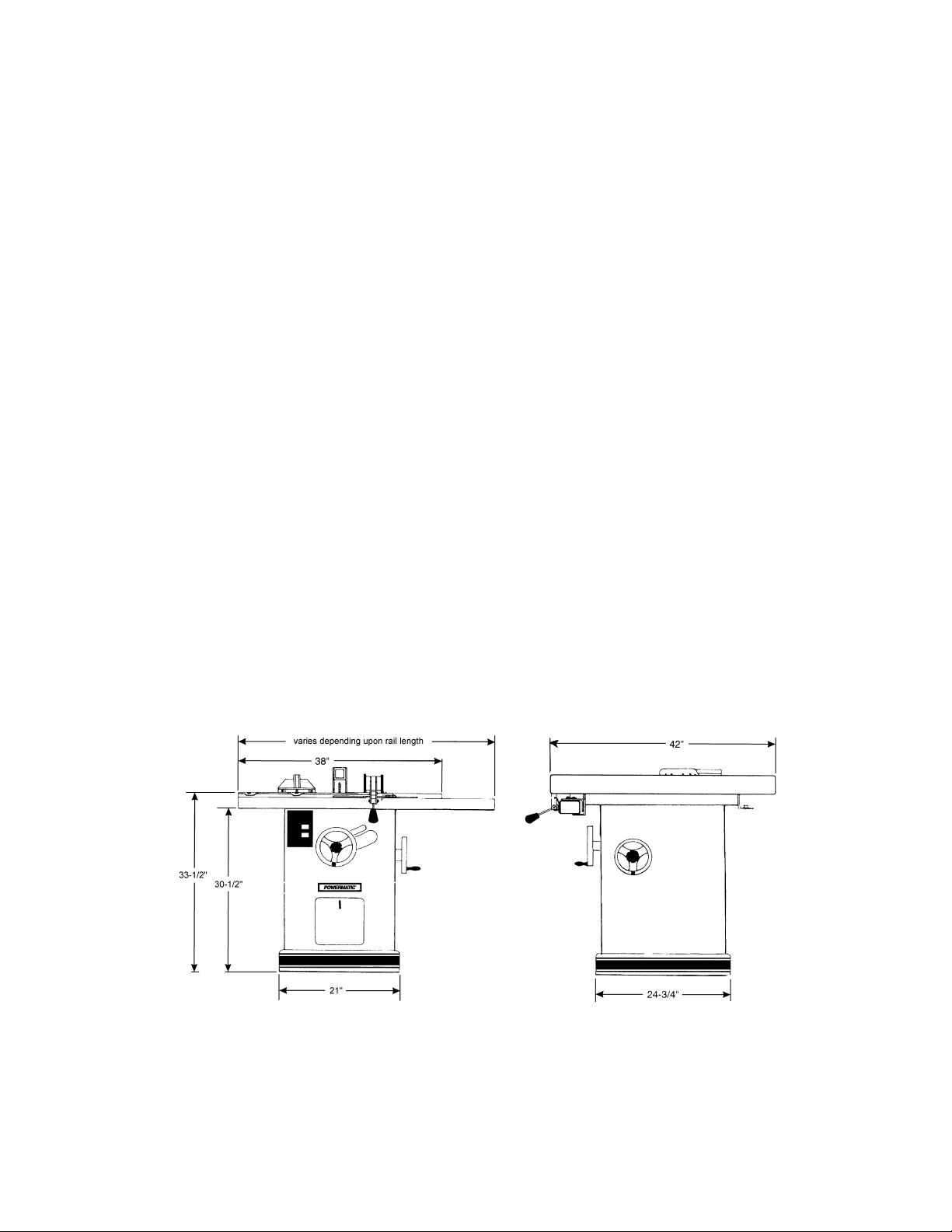
Specifications
Model number........................................................................................................................................66
Maximu m moto r size.........................................................................................................5HP, 3600 RPM
Table size with standard ex tensions (L x W)(in.) ....................................................................... 37-1/2 x 28
Table size without ex tension (L x W)(in.).................................................................................. 21-1/2 x 28
Rip fence (L x W x H)( in.)................................................................................................41-3/4 x 4 x 2-1/2
Arbor diameter (in.)...............................................................................................................................5/8
Saw blade diameter (i n.)........................................................................................................................10
Maximum speed of 10” saw blade (SFM ) ........................................................................................ 11,000
Blade tilt maxim um (deg. ) ......................................................................................................................45
Maximum depth of cut (in.).......................................................... 3-1/8 at 90-degrees; 2-1/8 at 45-degrees
Maximum cut to right of saw blade with st andar d extension (in.).............................................................25
Maximum width of cutoff in front of saw in 1” stock (i n.)..........................................................................15
Maximum width of cutoff in front of saw in 3-1/8” stock (in.)..............................................................12-1/4
Maximum diam eter of dado (in.)...............................................................................................................8
Maximum width of dado cut (i n.)........................................................................................................ 13/16
Drive belts ....................................................................................................................3VX (t wo required)
Table he igh t to flo o r ( in.)........................................................................................................................34
Dust port diameter (i n.) ............................................................................................................................4
Shipping weight wi th motor, fence and rails (lbs.).................................................................................614
The above specifications were current at the time this manual was publi shed, but because of our policy of
continuous im provement, WMH Tool Group reserv es the right to change specif ications at any tim e and
without pri or notic e, without incurring obligations.
6
Page 7
Unpacking
Open shipping cont ainer and check f or shipping
damage. Report any damage immediately to
your distributor and shipping agent. Do not
discard any shipping material until the Table
Saw is assembled and running properly.
Compare the cont ent s of y our cont ainer wit h the
following parts list to make sure all parts are
intact. Mi ssing parts, if any, should be reported
to your distributor. Read the instruction manual
thoroughly for assembly, maintenance and
safety instructions.
Contents of the Shipping Container
Box 1: 1 Table Saw
2 Extension Wings
1 Miter Gauge
1 Owner’s Manual
1 Warranty Card
Box 2: 1 Splitter and Guard Assembly
1 Splitter Support Shaft
Contents of Hardware Bag:
2 Arbor Wrenches
1 Hardware Bag*
Box 3: 1 Accu-Fence
1 Lock Handle
1 Accu-Fence Owner’s Manual
Box 4: 1 Front Rail
1 Rear Rail
1 Guide Tube
1 Hardware Bag
Box 5: 1 Motor Cover
2 Self-Tapping Screws
Optional:
Box 6: Formica Top Extension Table
Box 7: Legs for Extension Table
*The contents of the hardware bag are
illustrated below. The contents of the Accu-
Fence
Accu-Fence
and Rail hardware can be found in the
manual.
Read and understand the entire contents of this manual before attemp ting set-up
or operation! Failure t o co mpl y may cause seri ous injury.
7
Page 8
Installation and Assembly
Tools required for assembly:
7/16, 9/16, 3/8 and 1/ 2” wrenche s
1/8 and 3/32” hex wrenches
Flat head screwdriver
Hammer and wood block (or r ubber hammer)
1. Remove box and wood crating completely
from around saw.
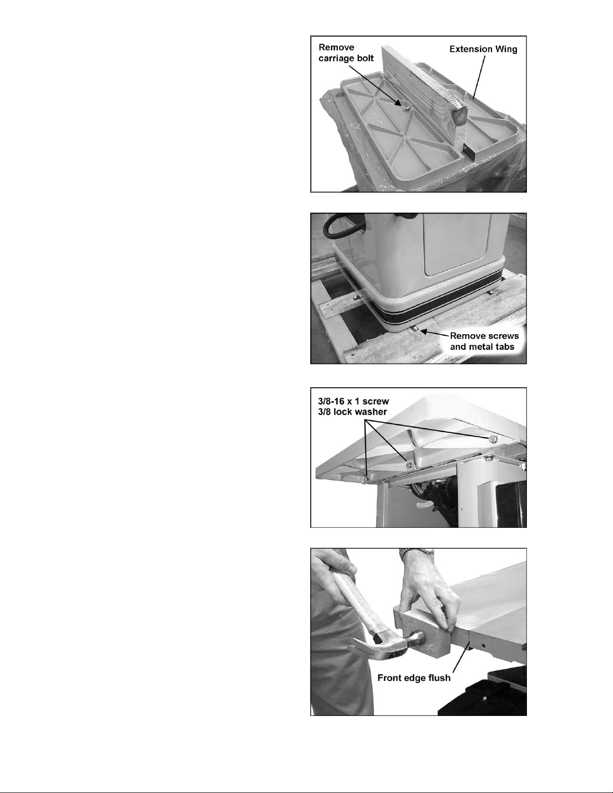
2. Use a 9/16” wrench t o remove the car riage
bolt, hex nut and washer holding the
extension wings together (Figure 1). Set
extension wings aside for later installation.
3. With a 7/16” wrench, rem ov e t he lag screws
(Figure 2) holding the saw to the wood
pallet. Caref ully sli de the saw from the pallet
onto the floor.
4. Tilt the saw, and pop off the metal tabs
(Figure 2) that secured the saw to the pallet,
by pushing down on them with y our foot .
The Table Saw sho uld be placed in an area with
a sturdy level floor, good ventilation and
sufficient lighting. Leave enough space around
the machi ne for mounting extension wing s and
rail assemblies, and loading and off-loading
stock and general maintenance work.
Figure 1
Figure 2
Exposed metal surfaces, such as the table top
and extension wings, have been given a
protectiv e coating at the fact ory. This should be
removed with a soft cloth moistened with
kerosene. Do not use acetone, gasoline, or
lacquer thinner for this purpose. Do not use
solvents on plastic parts, and do not use an
abrasive pad because it may scratch the
surfaces.
Mounting Extension Wings
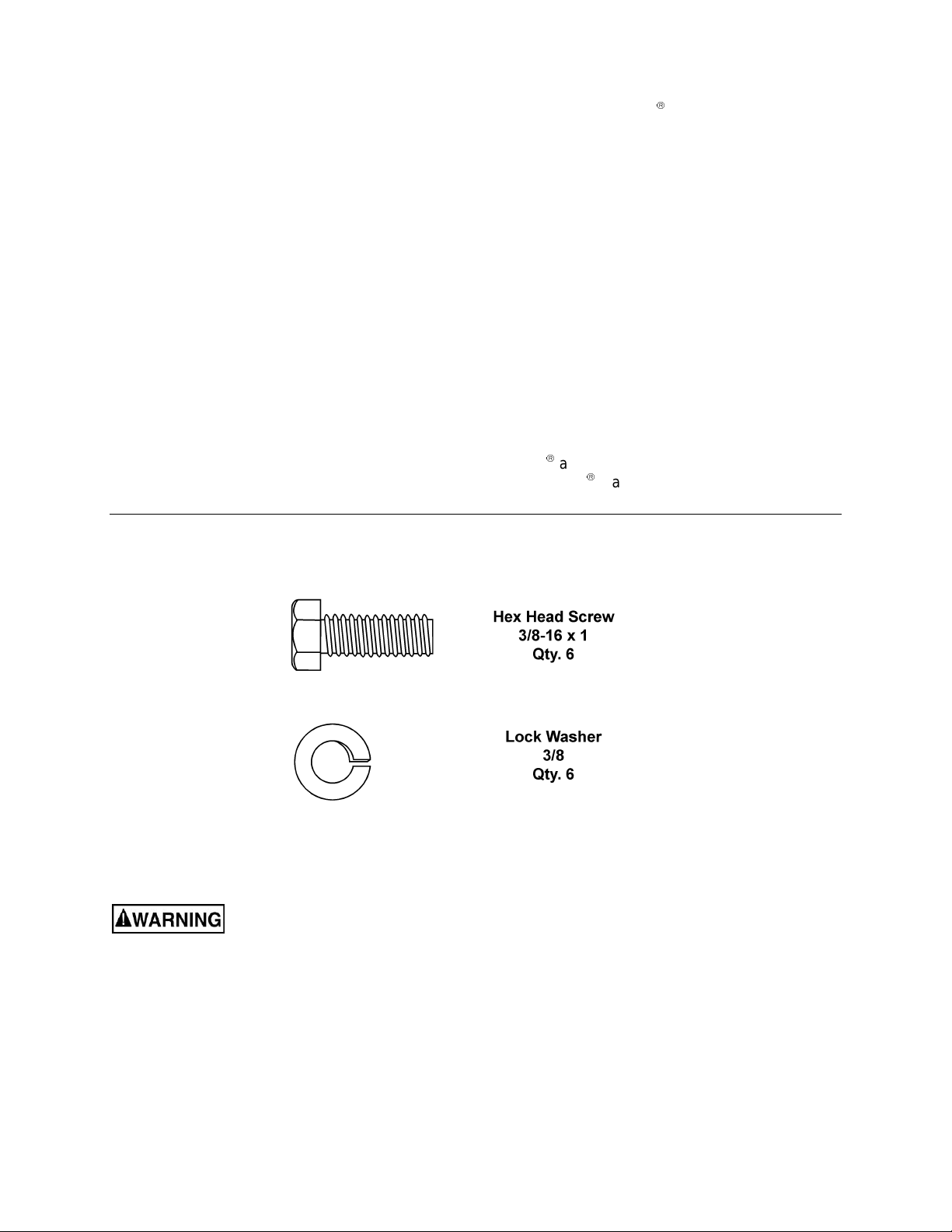
1. Mount the cast iron extension wings using
six 3/8-16 x 1 hex head screws and six 3/8
lock washers. See Figure 3. Have an
assistant hold t he extension wing up to the
table, and insert the screws and washers.
Finger tighten only.
NOTE: If an assistant i s not avail able, hold
the wing in vertical position up to the saw
table, insert the middle screw and lock
washer finger tight, then pivot the wing to
level position. Insert the other two screws
and washers fi nger tight .
2. It is important that the front edge of the wing
is flush with the front edge of saw table. S ee
Figure 4.
Figure 3
Figure 4
8
Page 9
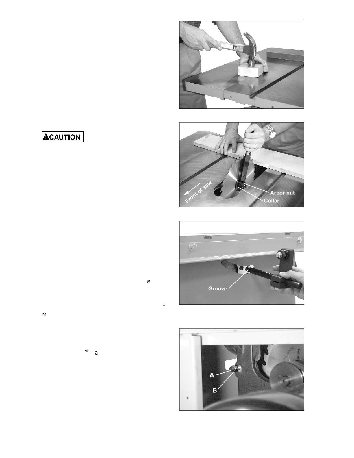
3. Level t he extension wing with the sa w table
across its enti re widt h, using a strai ght edge
and hammer with block of wood (or rubber
hammer). See Fi gure 5. As each area of the
wing becomes flush with the table, tighten
the screw under t hat area. Cont inue unti l all
three screws are fully tightened.
4. Repeat for the other ex tension wing.
Installing Blade
NOTE: The blade m ust be mounted first bef ore
rails can be adjusted.
To install or replac e a blade, proceed as follows:
Use care wh en working with
or around sharp saw blade.
1. Disconnect machine from power source.
2. Rem ove tabl e insert, then rem ove arbor nut
and collar.
3. Install blade, making sure the cutting teeth
at the top of t he blade poi nt toward the f r ont
of the saw.
Figure 5
4. Sli de the coll ar on to the ar bor and start the
arbor nut on the threads. (NOTE: Righthand threads; turn clockwise to tighten.)
Snug the arbor nut against the collar and
blade with the pr ovided arbor wrench, while
holding blade wit h thumb and finger tips.
5. Wedge a block of wood between the blade
and table to prevent blade rotation, then
tighten t he arbor nut securel y with the ar bor
wrench. See Figur e 6.
Mounting Rails and Accu-Fence
With the extension wings properly aligned, the
rail and f ence assem bl y can no w be m ounted t o
the saw. Consult the separate Accu-Fence
manual for instructions.
Optional Wood Extension Table
For instructions on mounting the accessory
wood extension table, or router table, consult
your Accu-F enc e
manual.
Splitter and Guard Assembly
Figure 6
Figure 7
1. Insert the grooved end of the splitter support
shaft through slot in rear of saw and into
hole in trunnion. See Figure 7. Make sure
the square head setscrew (A, Figure 8) is
backed out enough to allow easy insertion
of the splitter support shaft.
Figure 8
9
Page 10
2. With a 3/8" wrench, reach through the motor
s
opening in the stand and tight en the square
head setscrew (A, F igure 8) into the groov e
of the shaft. (NOTE: The groove will be in
the proper posi tion if the end of the shaf t is
made flush with the opposite side of the
trunnion hol e.) Then tighten the hex nut (B,
Figure 8) up against the trunnion.
3. The upright member of the rear splitter
support (C, Figure 9) must be oriented
toward the right of the shaft, as observed
from the rear of the saw.
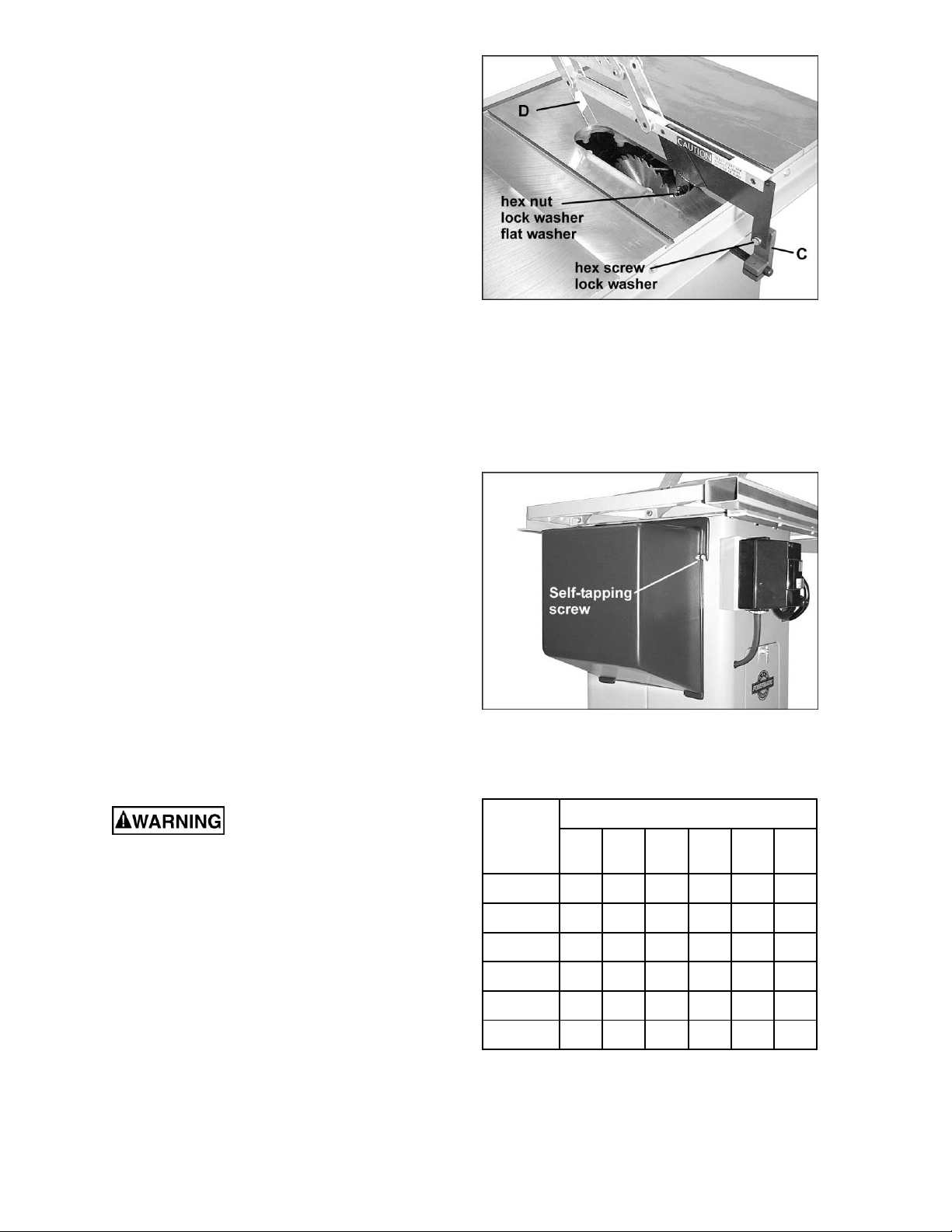
4. Mount the splitter assembly to the two
adjusting screws. See Figure 9. Place the
two flanges of t he spli tter assem bl y onto t he
crews as shown. S nug the scre ws. (NOT E:
Make sure the front shield (D, Figure 9)
faces in toward the blade)
5. The splitter and guard assembly must be
aligned wit h the blade before operati ng the
saw. Adjust the splitter according to the
directions on page 13, " S plitter Alignment."
Moto r Cover
Figure 9
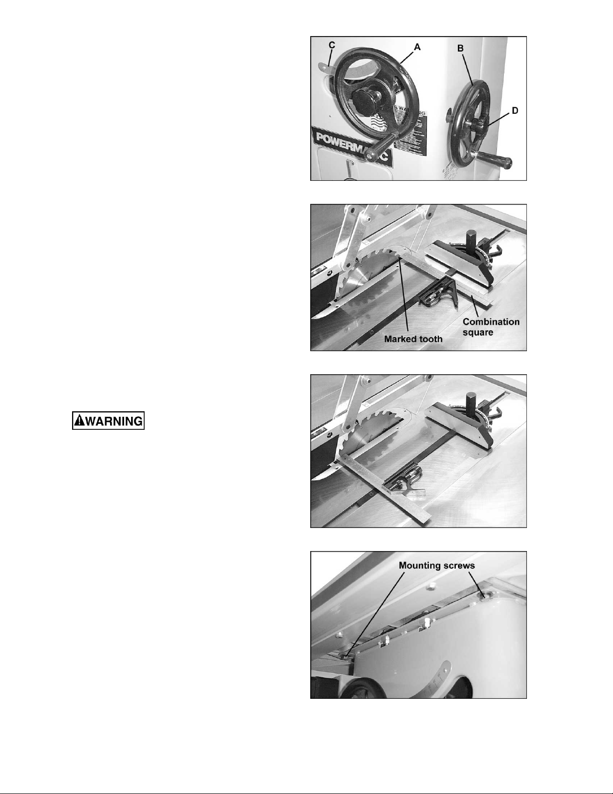
1. Locate the two 1/4-20 self tapping sheet
metal screws and install them in the
punched holes on the saw cabinet. Do not
screw down all the way, but leave t he heads
about 1/4" fr om the surf ac e. See Figure 10.
2. Lift the m otor cover over these scre ws with
the cover's bottom lip inside the saw's
cabinet.
3. Tighten the two screws.
Grounding Instructions
Electrical connections must
be made by a qualified electrician in
compliance with all relevant codes. This
machine must be properly grounded to help
prevent electrical shock and possible fatal
injury.
A power plug is not prov ided wit h the Model 66.
You may either connect the proper UL/CSA
listed pl ug or “hardwire” the mac hine directly t o
your electrical panel provided there is a
disconnect near the machine for the operator.
Consult electrical drawings on pages 33-36 for
further clarification of wiring setup.
This machine must be grounded. Grounding
provides a path of least resi stance to hel p divert
current away from the operator in case of
electrical malfunction.
Figure 10
Recommended Gauges (AWG) of Extension Cords
Extension Cord Length *
25
50
75
100
150
Amps
< 5 16 16 16 14 12 12
5 to 8 16 16 14 12 10 NR
8 to 12 14 14 12 10 NR NR
12 to 15 12 12 10 10 NR NR
15 to 20 10 10 10 NR NR NR
21 to 30 10 NR NR NR NR NR
*based on li miting the line voltag e dr op to 5V at 15 0% of t h e
rated amp eres.
NR: Not Recommended.
feet
feet
feet
feet
feet
200
feet
Figure 11
10
Page 11
Make sure the voltage of your power supply
matches the specif ications on the m otor plate of
the machine.
Extens ion Cords
If an extension cord is necessary, make sure the
cord rating i s suitable for the am perage listed on
the machine's motor plate. An undersize cord
will cause a drop in line voltage resulting in loss
of power and overheating.
The chart in Figure 11 shows the correct size
cord to use based on cord length and motor
plate amp rating. If in doubt, use the next
heavier gauge. The smaller the gauge number
the heavier the cor d.
Adjustments
Blade Raising and Tilting
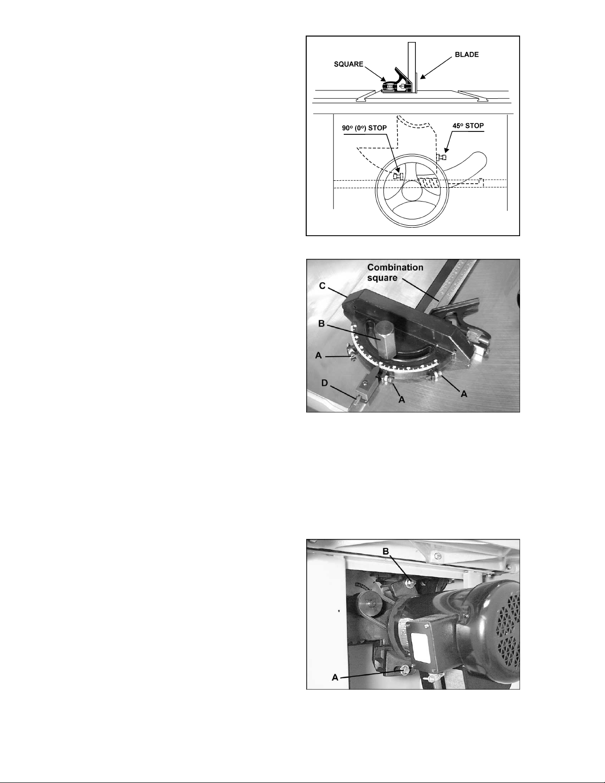
The front handwheel ( A, Figure 12) controls the
raising and lowering of the blade. The side
handwheel (B, Figure 12) controls blade tilt,
which is indicated by the scale (C, Figure 12).
The lock k nobs (D, Figure 12) are use d to lock
the setting of the handwheel s.
Figure 12
Figure 13
Miter Slot Alignment
Disconnect machine from
power source before making this
adjustment.
1. To check the alignment of the mitre slot to
the blade, raise the blade to its maximum
height at the 0 degree (vertical) position.
2. Mark one tooth with a grease pencil and
position the tooth slightly above the top
edge of the table at the front.
3. Raise the m iter gauge sli ghtly out of its slot
to serve as a shoul der. Using a com bi nat ion
square against the si de of the bar, slide t he
scale over until it touches the tip of the
blade, and lock the scale in position. See
Figure 13.
4. Rotat e the m arked t ooth so that i t is sl ightly
above the table top at the rear and, using
the square as before, check whether the
distance to the blade is the same. See
Figure 14. If the distance is not the same,
loosen the three m ounting screws that lock
the table t o the cabinet ( two in front , one in
back) as shown in Fi gure 15, and nudge the
table to bring the miter slot in line with the
blade.
Figure 14
Figure 15
11
Page 12
5. The blade must be kept centered with the
b
slot in the table insert to ensure clearance at
oth the 90 degree and 45 degree posi tions.
After alignment, secure the table to the
cabinet by re-tightening the three mounting
screws (Figur e 15) .
Tilt Stop Adjustment
Using a combination square, check the 90
degree (0) and 45 degree stops. (Figure 16
shows the 90 degree stop being checked.)
Adjust stop positi ons if required, using the stop
screws as shown. Check the accuracy of the
pointer at 90 degrees (0) and re-adjust if
required.
Miter Gauge Adjustment
1. Slide the miter gauge into one of the slots
on the table top.
2. The miter gauge is equipped with
individually adjustable index stops at 90
degrees and 45 degrees right and l eft. The
index stops can be adjusted by loosening
the hex nuts and turning t he three adjusting
screws (A, Figure 17) as needed. After
setting each stop, r etighten the hex nut.
Figure 16
3. To operate the miter gauge, loosen lock
handle (B, Fi gure 17) and move t he body of
the miter gauge (C, Figure 17) to the
desired angle. T he miter gauge body is set
to stop at 0 degrees and 45 degrees l eft or
right. To move the miter gauge beyond
these points, the stop rod (D, Figure 17),
must be pulled out.
4. If accurate crosscutting work is to be done
using the mit er gauge, check i t s squareness
to the slot wit h a square as shown in F igure
17. Re-adjust the st op posi tion as required.
Belt Tensioning
The saw is equipped with a set of two matched
belts. If they should need repl acement, replace
the complete set.
To tension the belts:
Loosen the hex screw (A, Figure 18) and nut (B,
Figure 18) on t he motor brac ket. Piv ot the mot or
and bracket to the right. Retighten screw (A,
Figure 18) and nut (B, Figure 18).
To remove and replace the belts, loosen the
screw (A, Fi gure 18) and nut (B , Fi gure 18) and
rotate t he mot or and brack et t o the l eft as f ar as
possible. Remove one belt at a time. After
installi ng new bel ts, re-tension as indicat ed.
Figure 17
Figure 18
12
Page 13

Splitter Alignment
One of the most critical adjustments to help
avoid kickback is the splitter adjustment. It
should be checked and readjusted, if required,
after each blade change.
1. Lift the miter gauge bar slightly out of its
slot. Place a combination square against the
side of the raised up miter gauge bar and
slide the scal e against the top of the blade
tooth and against the splitter as shown in
Figure 19.
2. Check the splitter for parallelism and for
clearance to the miter slot. If adjustment is
necessary, use the screws at the front
flange and at the rear splitter support.
3. Move the miter gauge to the opposite side
of the blade and using the combination
square, sli de the scale against the top of the
tooth and the splitter. Again check for
parallelism and clearance. Clearance should
be approxim ately equal on both si des of the
blade.
Insert Adjustment
Adjust the setscre ws in the insert wit h a 1/8 hex
wrench to ensure that the insert is stable and
flush with or slightly below the table top. See
Figure 20.
Arbor and Arbor Bearing Removal
1. To remove the saw arbor, first remove the
fence and rails, then remove the three
mounting screws holding the table to the
base (see Figure 15). Lift off the table.
Figure 19
Figure 20
2. Loosen the two set screws in the arbor
sheave (A, Figure 21) and remove the
sheave and key.
3. Loosen the set scre w (B, Figure 21) on the
saw raising arm. The arbor assembly and
bearings will slide out of the arm housing.
Blade Raising Mechanism
Adjustment
If bindi ng occ urs, cl ean off all sawdust and pi tc h
buildup and re-lubricate with a good nonhardening grease. If binding continues, check
the fit-up of the worm and worm gear segment.
The worm m ust be center ed wit h the worm gear
segment. If it is not centered, loosen the saw
raising arm set screws, move the arm as
required, and r e-l ock t he set screws. See Fi gure
22.
Figure 21
Figure 22
13
Page 14

If the saw raising arm has been re-locat ed, the
table may have t o be realigned so a s to provi de
clearance between the saw blade and table
insert slot. The splitter will also have to be
realigned.
NOTE: The saw arm set screw must be tight to
avoid the possibility of movement which could
cause the blade to hit the insert.
Tilting Mechanism Adjustment
If binding occ urs in the tilting m echanism, clean
off the saw dust and pitch ac cumulation and regrease. If binding continues, check the
alignment and readjust as required to center
worm with the worm gear segment on the
trunnion.
If there is excessive play, loosen bracket
mounting screws (A, Figure 23) and turn
adjustment screw (B, Figure 23) clockwise to
raise pinion. A tight mesh without binding is
ideal. Re-tighten mounting screws and check
over the 90 degree t o 45 degree range of tilt f or
excessive pl ay or binding. Re-adjust if required.
Operating Instructions for
Tabl e Saws
1. Familiarize yourself with the location and
operation of all controls and adjustments
and the use of accessories such as the
miter gauge and ri p fence.
2. Serious injury can result from kickbacks
which occur when a work piece binds on the
saw blade or binds bet wee n the saw blade
and rip fence or other fixed object. This
binding can cause the work piece to lift up
and be thrown toward the operator. Listed
below are the conditions which can cause
kickbacks:
• Confining the cutoff piece when
crosscutting or ripping.
• Releasing the work piece before
completing t he operation or not pushing
the work piece all the way past the saw
blade.
• Not using the splitter when ripping or not
maintaining alignment of the splitter with
the saw blade.
• Using a dull saw blade.
• Not maintaining alignment of the rip
fence so that it tends to angle toward
instead of away from the saw blade
front to back.
Figure 23
14
Page 15

• Applying feed f orce when ripping to the
r
cutoff (free) section of the work piece
instead of t he section between t he saw
blade and fence.
• Ripping wood that is twisted (not flat ), or
does not have a strai ght edge, or has a
twisted grain.
3. To minimize or prevent injury from
kickbacks:
Avoid conditions listed above.
Wear a safety face shield, goggles, or
glasses.
Do not use the miter gauge and rip
fence in the same operation unless
provision is made by use of a facing
board on the fence so as to allow the
cutoff secti on of the workpiece to com e
free befor e the next cut is started (See
Figure 32).
As the machine receives use, the
operation of the anti-kickback pawls
should be checked periodically. See
Figure 24. If the pawls do not stop the
reverse motion of a workpiece, resharpen all the point s.
Where possible, keep your face and
body out of l ine wit h potenti al kick backs
including when starting or stopping the
machine.
4. Dull, badl y set, improper, or im properly filed
cutting tools and cutting tools with gum or
esin adhering to t hem can cause acci dents.
Never use a cracked saw blade. T he use of
a sharp, well m aintained, and correct c utti ng
tool for the operation will help to avoid
injuries.
5. Support the workpiece properly and hold it
firmly against the gauge or fence. Use a
push stick or push block when ri pping short,
narrow (6" width or less), or thi n workpieces.
Use a push block or miter gauge hold-do wn
when dadoing or mol ding.
Figure 24
6. For incr eased safety in crosscutti ng, use an
auxiliary wood facing attached to the miter
gauge using the holes provided in the
gauge, Figure 25.
7. Never use the fence as a lengt h stop when
crosscutting. Do not hold or touch the free
end or cutoff section of a workpiece. On
through-sawing operations, the cutoff
section must NOT be confined.
8. Always keep your hands out of the line of
the saw blade and nev er reach back of the
cutting blade with either hand to hold the
workpiece.
Figure 25
15
Page 16

9. Bevel ripping cuts should always be made
with the fence on the right side of the saw
blade so that the blade tilts away from the
fence and minimizes the possibility of the
work binding and the r esul ting kickback.
Rip Sawing
1. Ripping i s where the work piece is fed wit h
the grain i nto the saw blade using the f ence
as a guide and a positioning device to
ensure the desired widt h of cut. See Figure
26.
Before starting a rip cut, be
sure the fence is clamped securely and
aligned properly.
Never rip freehand or use the miter gauge in
combination with the fence.
Never rip workpieces shorter than the saw
blade diamet er.
Never reach behind the blade with either
hand to hold down or remove the cutoff
piece with the saw blade rotat ing.
2. Al ways use the sa w guard, spli tter and ant ikickback pawls. Make sure the splitter is
properly aligned. When wood is cut along
the grain, the kerf tends to close and bind
on the blade and kick bac k s can occ ur.
Figure 26
NOTE: A caution decal is installed on the
guard and split ter assembly, warning of the
hazard of misalignment.
3. The ri p fence should be set for the width of
the cut by using the scale on the front rail, or
by measuring the distance between the
blade and fenc e. See Figure 27. Stand out
of line wi th the saw blade and workpiece to
avoid sawdust and splinters coming off the
blade or a kickbac k, if one should oc c ur .
4. If the workpiece does not have a straight
edge, provide one by nailing an auxiliary
straight edged board on i t to sli de along t he
fence. To cut properly, the boar d must make
good contact with the t able. If it is warped,
turn the hollow side down.
5. In ripping, use one hand to hold the board
down against the fence or fixture, and the
other to push i t into the blade between t he
blade and the fence. If the workpiece is
narrower than 6" or short er than 12", use a
push stick or push bl ock to push it through
between the fence and saw blade. See
Figure 28.
Figure 27
Figure 28
16
Page 17

6. Never push in a location such that the
r
t
pushing hand is in li ne with the blade. Move
the hand serving as a hold-down a safe
distance from the blade as the cut nears
completion.
7. For very narrow ri pping where a push stick
cannot be used, use a push block or
auxiliary fence. Always push the workpiece
completely past the blade at the end of a cut
to minimize the possibility of a kickback.
8. When ri pping long boards, use a support at
the front of the table, such as a roll er stand,
and a support or "tailman" at the rear as
shown in Figure 29.
9. Never use the rip fence beyond the point
where the carriage is flush with the end of
the rails.
10. Have t he bl ade extend about 1/8" abov e the
top of the workpiece. Exposing the blade
above this point can be haz ar dous.
Resawing
1. Resawing is a ripping operation in which
thick boa
Narrow boards up to 3" can be resawn in
one pass. Wider boards up to 6" must be
resawn in two pas ses.
2. In resawing wider boards, adjust the blade
height so as to over lap the two cuts by 1/2"
as shown in Fi gure 30. Too d eep a fi rst cut
can result i n binding and possibl e kickbacks
on the second cut. Always use the same
side of the boar d against the f ence f or both
cuts.
ds are cut into thinner ones.
Figure 29
Figure 30
Crosscutting
1. Crosscutting is where the workpiece is fed
cross grain into the saw blade using the
miter gauge to support and position the
workpiece. See Figure 31. Crosscutting
should never be done fr eehand nor should
the fence be use d as a n end stop unl ess an
auxiliary block is clamped in front of the
blade area such that t he cutoff piece comes
free of the block before cutting starts. See
Figure 32. Length stops should not be used
on the free end of the workpiece in the
cutoff area.
2. Do not
Before starting a cut, be sure the miter
gauge is securely clamped at the desired
angle. Hold the workpiece f irmly against the
able and back against the miter gauge.
Always use the saw guard and splitter and
make sure the splitt er is properly aligned.
crosscut workpieces shorter than 6" .
Figure 31
Figure 32
17
Page 18

3. For 90 degree crosscutting, most operators
prefer t o use the left-hand m iter gauge slot.
When using it in this position, hold the
workpiece against t he miter gauge with the
left hand and use t he right hand to adv ance
the workpiece, as sho wn in Figure 32. When
using the right hand slot for miter and
compound crosscutting so that the blade
tilts away from the miter gauge, the hand
positions are reversed.
4. When usi ng the miter gauge, t he workpiece
must be held fi rmly and advanced sm oothly
at a slow rate. If the workpiece is not held
firmly, it can vibr ate causing i t to bi nd on the
blade and dull the saw teeth.
5. To improve the effectiveness of the miter
gauge in crosscutting, some user s mount an
auxiliary wooden extension face (with a
glued-on strip of sandpaper) to the miter
gauge as shown in Figur e 33.
6. Prov ide auxiliary support f or any workpiece
extending beyond the table top with a
tendency to sag and lift up off the t abl e.
7. Stop rods can be used in the holes provi ded
in the miter gauge for repetitive work of
equal length. Do not use a stop rod on the
free end of a workpiece. It should be used
on the side of the miter gauge opposit e the
saw blade.
Figure 33
8. Have the blade ext end about 1/ 8" abov e t he
top of the workpiece. Exposing the blade
above this point can be haz ar dous.
Bevel and Miter Operations
1. A bevel cut is a special type of operation
where the saw blade is tilted at an angle
less than 90 degrees to the table top. See
Figure 34. Oper ations are performed in the
same manner as ripping or crosscutting
except the fence or miter gauge should be
used on the right -hand side of the saw blade
to provide added safety in avoiding a
binding action between the saw blade and
the table top. When beveling wi th the miter
gauge, the workpi ece must be hel d fi rmly to
prevent creeping.
2. Crosscuts made at an a ngle to the edge of
the workpiece are cal led miters. S ee Figure
35. Set and secure the miter gauge at the
required angl e, and make the cut the same
as a normal crosscut exc ept the workpiece
must be held extra firmly to prevent
creeping.
Figure 34
Figure 35
18
Page 19

NOTE: When making compound miters
(with blade t ilt ed) use the m i ter gauge in t he
right hand slot to provide more hand
clearance and safety.
3. Hav e the blade extend only 1/8" abov e the
top of the workpiece. Exposing the blade
above this point can be haz ar dous.
Dado Cutting
Dadoing is cutting a wide groove into a
workpiece or cutt ing a rabbet al ong the edge of
a workpiece. A dado i nsert, shown i n Figur e 36,
is necessary f or this ty pe of operation.
Do not use the standard
table insert for dadoing operations.
The process of cutti ng 1/8" to 13/ 16" groov es in
workpieces is accomplished by the use of a
stacked dado blade set or an adjustable blade
mounted on the saw arbor.
By using various combinations of the stacked
dado blades, or properly setting the dial on an
adjustable blade, an accurate widt h dado c an be
made. This is very useful for shelving, making
joints, tenoning, etc.
The guard, splitter, and anti-kickback pawls
supplied with the saw should be used for all
cutting operations where they can be used.
When performing operations where the guard
can not be used, as in some dadoing
operations, alternativ e safety precautions should
be taken. These include push sticks, feather
boards, fill er pieces, fixtures, jigs and any other
appropriate device that can be utilized to keep
operator's hands away from the blade.
Figure 36
Upon completion of the operation requiring
removal of the guard, the ent i re guard a ssem bl y
must be placed back on the machine in its
proper working order.
Never use a dado head in a
tilted position. Never operate the saw
without th e guard, splitter an d anti-kickback
pawls for operations where they can be
used.
Safety Devices
Feather Board (Figure 37).
The feather board should be made of straight
grain hardwood approx imately 1" thick and 4" to
8" wide depending o n the size of t he machine.
The length is developed in accordance with
intended use.
Feather boards can be fastened t o the table or
rip fence by use of C-clam ps.
Figure 37
19
Page 20

Alternatively, drilled and tapped holes in the
l
table top allow the use of wing nuts and washers
as a method of clamping. If this method of
fastening is used, provide slots in the feather
board for adjustm ent.
Figure 37 shows a m ethod of at taching and use
of the feather board as a vertical comb. The
horizontal application is essentially the same
except that the attachment is to the table top.
Filler Piece (Fi gur e 38) .
A filler piec e is necessary f or narr ow rippi ng and
permits the guar d to remain on the machi ne. It
also provi des space for the safe use of a push
stick.
Push Block & Push Stick (Figures 39 & 40).
These items help feed the workpiece along
fence and blade while keeping the operator's
hands at a safe distance from the blade.
Maintenance
Good saw operation requires periodic pr ev entive
maintenance.
Keep the inside of the c abinet and t runnion area
clean. A stif f brush will remove sawdust before
it cakes and pi tch or gum is easil y rem oved wit h
a commercial solvent or with a good oven
cleaner. To accomplish this, remove the tabl e
by removing the three mounting screws (see
Figure 15) and exposing the working
mechanisms of the saw. After c leaning the tilting
and raising worm and worm gear segm ents and
the trunnions, grease these three areas with a
good grade non-hardening grease.
Check periodically for excessive play in the
tilting and raising mechanism and in the saw
arbor and re-adjust as required.
Check periodical
Readjust or repl ac e belts as required.
The table surf ac e m ust be k ept clean and free of
rust for best result s. Apply a coat of paste wax
to the surface to facilitate this. An alternative is
to apply white talcum powder, rubbed in
vigorously once a week with a blackboard
eraser; this will fill casting pores and form a
moisture barrier. This method provides a table
top that is slick and all ows rust rings to be easi ly
wiped from the surface. Important also is the
fact that talcum powder will not stain wood or
mar finishes as wax pi ckup does.
y for belt tension and wear.
Figure 38
Figure 39
20
Page 21

Figure 40
21
Page 22

Troubleshooting
Trouble Probable Cause Remedy
Excessive vibration.
Cuts out-of- square
when crosscutting.
Motor stalls or
workpiece binds or
burns.
Cuts not true at 90 or
45 degrees.
Tilt or raising cl am p k nobs not
tightened.
Blade out of balance. Change blade. [page 9]
Bad motor. Replace motor.
Loose arbor or motor sheave. Tighten set screws. [page 13]
Miter gauge out of adj ustm ent. Reset stops and pointer. [page 12]
Miter slot mi sali gned. Realign table. [page 11]
Excessive feed. Reduce feed.
Bad motor. Replace motor.
Dull or incorrec t blade. Replace blade. [page 9]
Miter slot mi sali gned. Realign miter sl ot. [page 11]
Fence misalignment. Realign fence. [see Fence manual]
Stop screws not set properl y . Readust stop screws. [ page 12]
Lock knob not released. Loosen lock knob.
Tighten knobs.
Tilt or saw raising
handwheels diff icult
to turn.
Motor overheat s.
Motor starts slowly or
fails to come up to
speed.
Motor fails to develop
full power.
Worm and worm gear segment caked
with sawdust and pit c h.
Worm and worm gear segment out of
alignment.
Motor overloaded.
Improper cooling of motor.
Low voltage.
Centrifugal swit c h not operating. Replace switch.
Bad motor. Replace motor.
Power line overloaded. Correct overload c ondition.
Undersize wires in supply system. Increase supply wir e si z e.
Low voltage.
Clean and re-grease.
Realign worm and worm gear
segment. [page 13]
Correct overload c ondition such as
reducing the feed rate.
Clean sawdust from fan and duct
areas of motor.
Request voltage check from power
company and correct low voltage
condition.
Request voltage check from power
company and correct condition.
Bad motor. Replace motor.
22
Page 23

Optional Accessories
709689 Scoring Saw attachment retrofit kit.
2042335 M obile base extended for Model 66 Saw (closed stand).
2042336 M obile base standard (fits saw stand only ) .
2042342 M obile base open bottom for Model 66 Saw (open stand).
2042372 M obile base with 30" fence with Rout-R-Lift.
2195042K Accu-Fence
2195079 Accu-Fence
2195049K Accu-Fence
2195063K Accu-Fence
2250116 B lade guard and Splitter Assembl y . Wt. 10 lbs. (4.5 kg).
2328001 Table Insert.
2328002 Dado Insert Plate for 8" dado head. Wt. 1 lb. (.45 kg).
2726008 Replacement side panel kit for Model 66 Accu-Fence
2440020 Rear Loc k A ssem bly for Accu-Fence
2471015 M iter Gauge. Wt. 4 lbs. (1.8kg).
3104663 M otor cover (old style).
3104667 M otor cover for serial # 95662522 and up
3186008 8" ( 203.2 mm) Cast Iron Extension Wing.
6080143 B lade 35 tooth carbide tip.
6080144 B lade 50 tooth carbide tip.
6253118K S liding Table Retrofi t Kit, 50" crosscut capac ity.
6284600 Tenoning Jig.
2328003 Zero Clearance Insert.
6441000 S et of 2 legs for 6827028 table.
6682004 Rout-R-Lift with delux e fence.
6827028 Formica topped table f or 50" c apaci ty T-square system.
6827031 Table 28" x 35-3/8" with Rout- R- Lift hole for model 66 saw.
6827032 Table 28" x 24" with Rout-R-Lif t hole for model 66 saw.
and rail system for rippi ng 50" to ri ght and 12" to left of saw blade.
- fence assembly only, no rails - for Model 66.
and rail system for Model 66 w/sli ding table.
and rail system for rippi ng 30" to ri ght and 12" to left of saw blade.
.
.
Replacement Parts
Replacement part s are li sted on the f ollowing page s. To order par ts or reac h our servi ce depar tment, call
1-800-274-6848 between 7:00 a.m. and 6:00 p.m. (CST), Monday through Friday. Having the Model
Number and Serial Number of your machine available when you call will allow us to serve you quickly and
accurately.
23
Page 24

Parts List: Trunnion Assembly
Index No. Part No. Description Size Qty
................. 2810012.................. Trunnion Assembly (Items 1 thr u 65) ............ .........................................1
................. 2271035.................. Handwheel Assembl y (Item s 2 thr u 7).......... .........................................2
2............... 2271036.................. Handle Assembly (It em s 4, 6, 7) .................. .........................................2
3............... 3271084.................. Handwheel ..................................................8” diameter.......................2
4............... 3271085.................. Handle......................................................... .........................................2
5............... TS-1524031 ............ Socket Set Screw*.......................................M8 x 12.............................2
6............... 6716221.................. Slotted Fillister Head Cap Screw* ................M10 x 95.25......................2
7............... 6516029.................. Hex Jam Nut*..............................................M10 ..................................2
8............... 2810013.................. Center Trunnion Sub-Assembly .................. .........................................1
(Items 9, 25, 29, 30, 35, 40 thru 43, and 46)
9............... 3810041.................. Center Trunnion with Fasteners (Item s 29, 30, 59, 60) ...........................1
................. 2701010.................. Tilting Bracket Assembly (Items 11 thru 18, 64)......................................1
................. 2865001.................. Tilting Shaft Assembly (Items 13, 15, 16)..... .........................................1
11.............3065006.................. Tilting Br a ck e t.............................................. .........................................1
13.............3701031.................. Tilting Sh aft ................................................. .........................................1
14.............6861901.................. Nylon Washe r*.............................................E12, 3/4 I.D.......................4
15.............6626080.................. Spring Pin* ..................................................5mm dia. x 28...................2
16.............3865001.................. Worm........................................................... .........................................2
17.............3096247.................. Shaft Collar with Fasteners.......................... .........................................2
18.............TS-1520411............ Socket Set Screw*.......................................M8 x 8...............................4
19.............3582222.................. Shaft Locking Pin......................................... .........................................2
20.............3237360.................. Gear Segment with Fasteners (I tems 21 thru 24) ...................................1
21.............TS-1491061............ Hex Head Cap Screw*.................................M10 x 40...........................1
22.............TS-2210451............ Hex Head Cap Screw*.................................M10 x 45...........................1
23.............TS-1550071............ Flat Washer*................................................M10..................................2
24.............TS-2361101............ Lock Wash e r *..............................................M10..................................2
25.............2025039.................. Bearing Arm Assembly (Items 26 thru 34).... .........................................1
26.............3025265.................. Bearing Arm ................................................ .........................................1
27.............6714273.................. Stud*...........................................................M12 x 67...........................1
28.............6714274.................. Square Head Set Screw* .............................M10 x 25...........................1
29.............TS-149105.............. Hex Head Cap Screw*.................................M10 x 35...........................1
30.............6516029.................. Hex Jam Nut................................................M10..................................1
31.............2087001.................. Dust Chute .................................................. .........................................1
32.............TS-1490011............ Hex Cap Scre w* ..........................................M8 x 12.............................1
33.............TS-1551051............ Lock Wash e r *..............................................M8....................................1
34.............TS-1525021............ Socket Set Screw*.......................................M10 x 12...........................1
35.............2690067.................. Screw Assembly Splitter* (Items 36 thru 39). .........................................1
36.............3691046.................. Adjusting Screw........................................... .........................................1
37.............6572007.................. Spanner Nut ................................................M20 x 1.5..........................1
38.............TS-1491021............ Hex Head Cap Screw ..................................M10 x 20...........................1
39.............TS-2361101............ Lock Wash e r ................................................M10..................................1
40.............3711005.................. Pivot Shaft................................................... .........................................1
41.............6811327.................. Spacer......................................................... .........................................2
42.............6578006.................. Hex Nut*......................................................1
43.............6670092.................. Retainer Ring*............................................. .........................................1
44.............3480015.................. Motor Mount................................................ .........................................1
45.............3810023.................. Front Trunnion............................................. .........................................1
46.............2865002.................. Raising Shaft Assembly (Items 15, 16, 47)... .........................................1
47.............3701032.................. Raising Shaft............................................... .........................................1
48.............3735075.................. Spacer......................................................... .........................................1
................. 2024018.................. Arbor Assembly (Items 52 thru 58)............... .........................................1
52.............3700123.................. Arbor Shaft .................................................. .........................................1
53.............6670015.................. Retainer Ring...............................................#5100-78 ..........................2
54.............3737214.................. Spacer......................................................... .........................................1
55.............6060009.................. Bearing NSK................................................6204 .................................2
56.............6863004.................. Wavy Wash er..............................................W1819-020.......................1
57.............3838006.................. Collar........................................................... .........................................1
1
/8 -12..............................1
24
Page 25

Index No. Part No. Description Size Qty
58.............3530006.................. Nut..............................................................5/8-12 ACME....................1
59.............3604036.................. Pointer......................................................... .........................................1
60.............6780015.................. Button Head Socket Cap Screw*..................M4 x 10.............................1
61.............6780016.................. Square Head Set Screw* .............................M10 x 65...........................1
63.............3810040.................. Rear Trunnion.............................................. .........................................1
64.............6420002.................. Woodruff Key...............................................#608 .................................3
65.............3868032.................. Arbor Wren ch.............................................. .........................................2
66.............3700090.................. Splitter Support Shaft................................... .........................................1
67.............6716035.................. Hex Head Screw..........................................3/8-16 x 1-3/4....................4
68.............6861300.................. Lock Was h e r................................................3/8..................................10
69.............6516001.................. Hex Nut.......................................................3/8-16...............................6
70.............6714159.................. Socket Set Screw........................................1/4-20 x 3/8.......................1
71.............6807132.................. Arbor Sheave...............................................2-Groove........................... 1
72.............6716031.................. Hex Head Screw..........................................3/8-16 x 1..........................1
73.............6861501.................. Flat Washer.................................................1/2....................................2
74.............6518001.................. Hex Nut.......................................................1/2-13...............................2
75.............6472028.................. Electric Motor, 3HP, 1Ph, 3600 RPM, 230V, 145 TC Frame...................1
................. 6472033.................. Electric Motor, 3HP, 1Ph, 3600 RPM, 230V, 145 TC Frame (50Hz)
................. 6471720.................. Electric Motor, 2HP, 3Ph, 3600 RPM, 230/460V, 145 TC Frame
................. 6471723.................. Electric Motor, 2HP, 1Ph, 3600 RPM, 115/230V, 145 TC Frame
................. 6472024.................. Electric Motor, 3HP, 3Ph, 3600 RPM, 200V, 147 TC Frame
................. 6472025.................. Electric Motor, 3HP, 3Ph, 3600 RPM, 230/460V, 145 TC Frame
................. 6472307.................. Electric Motor, 5HP, 3Ph, 3600 RPM, 230/460V, 184 C Frame
................. 6472335.................. Electric Motor, 5HP, 1Ph, 3600 RPM, 230V, 184 C Frame
76.............6718017.................. Hex Head Cap Screw..................................1/2-13 x 1-3/4....................1
77.............6807133.................. Motor Sheave..............................................2-Groove...........................1
78.............6715013.................. Socket Set Screw........................................5/16-18 x 3/8.....................1
79.............6077225.................. Belt (2 required)........................................... .........................................2
80.............6516009.................. Hex Jam Nut................................................3/8-16...............................1
81.............6716079.................. Square Head Screw .....................................3/8-16 x 1..........................1
82.............6716082.................. Square Head Screw .....................................3/8-16 x 2-1/2....................1
................. 2380019.................. Hardware Kit* (not shown) .......................... ...........................................
* Items included with hardware kit.
25
Page 26

Trunnio n Assembly
26
Page 27

Parts List: Miter Gauge
Index No. Part No. Description Size Qty
................. 2471015.................. Mitre Gauge Assembly (Item s 1 Thru 14)........... ...................................1
1............... 3044053.................. Mitre Gauge Bar................................................ ...................................1
2............... 3230038.................. Mitre Gauge....................................................... ...................................1
3............... 3604035.................. Mitre Gauge Pointer........................................... ...................................1
4............... 3585221.................. Stop Pin............................................................. ...................................1
5............... 3841202.................. Mitre Gauge Bar Washer ................................... ...................................1
6............... 6506001.................. Hex Nut............................................................. # 6-32.........................3
7............... 6623012.................. Dowel Pin ..........................................................1/4 x 1 ........................1
9............... 6706015.................. Fillister Head Machi ne Screw............................. 6-32 x 5/8...................3
11.............6714053.................. Flat Head Cap Screw......................................... 1/4-20 x 3/8 ................1
12.............6861101.................. Plain Flat Washer.............................................. 1/4..............................1
13.............3695221.................. Locking Screw................................................... 1/4 x 3-3/8..................1
14.............3268050.................. Mitre Gauge Handle Knob.................................. ...................................1
15.............3055435.................. Pointer Blo ck ..................................................... ...................................1
27
Page 28

Parts List: Splitter and Guard Assembly
Index No. Part No. Description Size Qty
................. 2787008.................. Splitter Rear Support Assembly (It em s 1 thru 7) ...................................1
1............... 6715034.................. Hex Head Cap Screw........................................ 5/16-18 x 1-1/4...........1
2............... 6861200.................. Lock Was h e r......................................................5/16............................1
3............... 3776050.................. Splitter Rear Support ........................................ ...................................1
4............... 6572007.................. Spanner Lock Nut.............................................. 3/4-16 ........................1
5............... 3690232.................. Adjustm ent Screw.............................................. 3/4-16 x 1-1/2 ............1
6............... 2406001.................. Knob Assembly.................................................. ...................................1
7............... 3700090.................. Splitter Support Shaft ........................................ ...................................1
................. 2250116.................. Guard and Splitter Assembly (Items 8 thru 28)... ...................................1
8............... 6851101.................. Flat Washer.......................................................1/4..............................2
9............... 6714158.................. Hex Head Cap Screw........................................ 1/4-20 x 5/8 ...............1
10.............6714192.................. Flat Head Socket Screw.....................................1/4 x 20 x 7/8..............8
11.............3250112.................. Blade Guard ..................................................... ...................................2
12.............3838015.................. Pivot Was h e r..................................................... ...................................4
13.............6514012.................. Lock Nut............................................................ 1/4-20.........................4
14.............6626029.................. Spring Pin.......................................................... 3/16 x 1 ......................1
15.............6626050.................. Spring Pin.......................................................... 3/8 x 1-3/4..................1
16.............3720018.................. Guard Shi eld...................................................... ...................................1
17.............6710032.................. Round Head Machine Screw.............................. No. 10-24 x 1/4...........2
18.............3720017.................. Front Shield....................................................... ...................................1
19.............6714053.................. Flat Head Machine Screw.................................. No. 10-24 x 3/8...........2
20.............3055095.................. Pivot Bl ock......................................................... ...................................1
21.............3025074.................. Pivot Arm........................................................... ...................................4
22.............3070108.................. Pivot Bushing..................................................... ...................................8
23.............6514001.................. Hex Nut............................................................. 1/4-20.........................2
24.............3581006.................. Anti-kickback Pawl............................................. ...................................2
25.............3044307.................. Splitter Bar......................................................... ...................................1
26.............3750011.................. Splitter............................................................... ...................................1
27.............3735203.................. Spacer............................................................... ...................................2
28.............3837206.................. Washer.............................................................. ...................................4
29.............6861301.................. Flat Plain Washer.............................................. 3/8 ............................1
30.............3330285.................. Caution Label (not shown) ................................. ...................................1
28
Page 29

Splitter and Guard Assembly
29
Page 30

Parts List: Stand Assembly
Index No. Part No. Description Size Qty
1............... 6716031.................. Hex Head Screw................................................ 3/8-16 x 1...................9
2............... 6861300.................. Lock Was h e r......................................................3/8..............................9
3............... 3186008.................. Standard Extension ........................................... 8"................................2
................. 2328002.................. Dado Insert Assembl y (Item s 4 & 5) .................. ...................................1
4............... 6714081.................. (Pkg of 5) Socket Set Screw (Nylok).................. 1/4-20 x 3/8................1
5............... 3328026.................. Dado Insert........................................................ ...................................1
................. 2136002.................. Door Assembly (Items 21 & 22).......................... ...................................1
6............... 3136018.................. Dust Removal Door............................................ ...................................1
7............... 6440003.................. Latch................................................................. ...................................1
8............... 3604003.................. Pointer............................................................... ...................................1
9............... 6708045.................. Round Head Machine Screw.............................. # 8-32 x 3/8................1
10.............3684232.................. Plated Tab le Angle Sc a le................................... ...................................1
11.............6746001.................. Pan Head Self-Tapping Screw........................... 6-32 x 1/4...................2
12.............2759036.................. Stand Assembly (Weldment).............................. ...................................1
13.............6861301.................. Flat Washer.......................................................3/8..............................3
14.............3797044.................. Table................................................................. ...................................1
................. 2328001.................. Table Insert Assembly (Items 4 & 15)................. ...................................1
15.............3328025.................. Table Insert ....................................................... ...................................1
16.............3104667.................. Motor Cover (Optional) ...................................... ...................................1
17.............6715101.................. Square Head Screw ........................................... 5/16-18 x 2-3/4 ...........2
18.............6515001.................. Hex Nut............................................................. 5/16-18.......................2
19.............6746023.................. Hex Head Self-Tapping Screw........................... 1/4-20 x 5/8................2
20.............3408257.................. Warning Label (not shown) ................................ ...................................1
30
Page 31

Stand Assembly
31
Page 32

Parts List: Table Extension and Legs (Optional Accessory)
Index No. Part No. Description Size Qty
................. 2389003.................. Extension Kit (Items 1 thru 10) .......................... ...................................1
................. 2423001.................. Extension Table Support Leg Assembly (Items 1 thru 8) ........................1
1............... 2423006.................. Inner Extension Leg Assembly........................... ...................................1
2............... 3186009.................. Outer Extension Leg.......................................... ...................................1
3............... 6515001.................. Hex Nut............................................................. 18-5/16.......................2
4............... 6861200.................. Lock Was h e r......................................................5/16............................2
5............... 6715036.................. Hex Head Screw................................................ 5/16-18 x 5/8 ..............2
6............... 6716031.................. Hex Head Screw................................................ 3/8-16 x 1 ..................7
7............... 6861300.................. Lock Was h e r......................................................3/8..............................7
8............... 6861201.................. Flat Washer.......................................................5/16............................2
9............... 3186010.................. Round Extension ............................................... 21"..............................1
10.............3186011.................. Square Exension ............................................... 21" ............................. 1
32
Page 33

Electrical Connections
33
Page 34

34
Page 35

35
Page 36

36
Page 37

Maintenance Checklist
Model 66 Table Saw
These should be performed monthly, or more frequently if needed:
[ ] Inspect entire machine for loose bolts, nuts, screws. Tight en and r eplace as necessary.
[ ] Thoroughly cl ean trunnion area, removing sawdust and c hips with soft bristle brush.
[ ] Remove pitch from t r unnions, quadr ant gears, elevating and tilt worm gears, and saw blades
using oven cleaner.
[ ] Lubricate trunnions, quadrant gears, elev ating and tilt worm gears with a good grade, non-
hardening lit hi um - based grease.
[ ] Clean table surface. If rusted, use paste mixture of household ammonia, a good commercial
detergent and 000 steel wool . Wash table down with hot, soapy water, rinse and dry
thoroughly. Coat surface with baby powder, rubbing br iskly into surfac e with a clean
blackboard eraser. A subsequent l ight coat of paste wax is recomm ended.
[ ] Check belt condi tion and tension; replace as needed.
[ ] Check motor for loose wiri ng and sa wdust c ongestion, pull ey s tight and in line.
[ ] Check all bearings. Replace any bad or suspect bearings immediately.
[ ] Check and reset blade stops at 45 degree and 90 degr ee posi tions.
[ ] Check guard and splitter alignment and operati on. Reset as needed.
[ ] Check miter gauge stops for accuracy.
37
Page 38

NOTES
38
Page 39

39
Page 40

WMH Tool Gr ou p
2420 Vantage Drive
Elgin, Illinois 60123
Phone: 800-274-6848
www.wmhtoolgroup.com
40
 Loading...