

Page 1

This .pdf document is bookmarked
Operating Instructions and Parts Manual
10-inch Contractor Table Saw
Model 64B
Powermatic
427 New Sanford Road
LaVergne, Tennessee 37086 Part No. M-1791229
Ph.: 800-274-6848 Revision B 04/2014
www.powermatic.com Copyright © 2014 Powerm atic
Page 2

1.0 Warranty and Service
Powermatic warrants every product it sells against manufacturers’ defects. If one of our tools needs service or repair,
please contact Technical Service by calling 1-800-274-6846, 8AM to 5PM CST, Monday through Friday.
Warranty Period
The general warranty lasts for the time period specified in the literature included with your product or on the official
Powermatic branded website.
• Powermatic products carry a limited warranty which varies in duration based upon the product. (See chart
below)
• Accessories carry a limited warranty of one year from the date of receipt.
• Consumable items are defined as expendable parts or accessories expected to become inoperable within a
reasonable amount of use and are covered by a 90 day limited warranty against manufacturer’s defects.
Who is Covered
This warranty covers only the initial purchaser of the product from the date of delivery.
What is Co vered
This warranty covers any defects in workmanship or materials subject to the limitations stated below. This warranty
does not cover failures due directly or indirectly to misuse, abuse, negligence or accidents, normal wear-and-tear,
improper repair, alterations or lack of maintenance.
Warranty Limitations
Woodworking products with a Five Year Warranty that are used for commercial or industrial purposes default to a
Two Year Warranty. Please contact Technical Service at 1-800-274-6846 for further clarification.
How to Get Technical Support
Please contact Technical Service by calling 1-800-274-6846. Please note that you will be asked to provide pro of
of initia l p u rch a s e whe n calling. If a product requires further inspection, the Technical Service representative will
explain and assist with any additional action needed. Powermatic has Authorized Service Centers located throughout
the United States. For the name of an Authorized Service Center in your area call 1-800-274-6846 or use the Service
Center Locator on the Powermatic website.
More Informa t ion
Powermatic is constantly adding new products. For complete, up-to-date product information, check with your local
distributor or visit the Powermatic website.
How S tate Law Ap plies
This warranty gives you specific legal rights, subject to applicable state law.
Limitations on This Warranty
POWERMATIC LIMITS ALL IMPLIED WARRANTIES TO THE PERIOD OF THE LIMITED WARRANTY FOR EACH
PRODUCT. EXCEPT AS STATED HEREIN, ANY IMPLIED WARRANTIES OF MERCHANTABILITY AND FITNESS
FOR A PARTICULAR PURPOSE ARE EXCLUDED. SOME STATES DO NOT ALLOW LIMITATIONS ON HOW
LONG AN IMPLIED WARRANTY LASTS, SO THE ABOVE LIMITATION MAY NOT APPLY TO YOU.
POWERMATIC SHALL IN NO EVENT BE LIABLE FOR DEATH, INJURIES TO PERSONS OR PROPERTY, OR
FOR INCIDENTAL, CONTINGENT, SPECIAL, OR CONSEQUENTIAL DAMAGES ARISING FROM THE USE OF
OUR PRODUCTS. SOME STATES DO NOT ALLOW THE EXCLUSION OR LIMITATION OF INCIDENTAL OR
CONSEQUENTIAL DAMAGES, SO THE ABOVE LIMITATION OR EXCLUSION MAY NOT APPLY TO YOU.
Powermatic sells through distributors only. The specifications listed in Powermatic printed materials and on the official
Powermatic website are given as general information and are not binding. Powermatic reserves the right to effect at
any time, without prior notice, those alterations to parts, fittings, and accessory equipment which they may deem
necessary for any reason whatsoever.
Product Listing with Warranty Period
90 Days – Parts; Consumable items
1 Year – Motors, Machine Accessories
2 Year – Woodworking Machinery used for industrial or commercial purposes
5 Year – Woodworking Machinery
NOTE: Powermatic is a division of JPW Industries, Inc. References in this document to Powermatic also apply to
JPW Industries, Inc., or any of its successors in interest to the Powermatic brand.
2
Page 3

2.0 Table of contents
Section Page
1.0 Warranty and Service ..................................................................................................................................... 2
2.0 Table of contents ............................................................................................................................................ 3
3.0 Safety warnings .............................................................................................................................................. 4
3.1 Kickback ..................................................................................................................................................... 5
4.0 About this manual .......................................................................................................................................... 6
5.0 Glossary ......................................................................................................................................................... 7
6.0 Features ......................................................................................................................................................... 8
7.0 Specifications ................................................................................................................................................. 8
8.0 Setup and Assembly .................................................................................................................................... 10
8.1 Shipping contents ..................................................................................................................................... 10
8.2 Unpacking and cleanup ............................................................................................................................ 11
8.3 Stand assembly ........................................................................................................................................ 12
8.4 Mounting saw to stand ............................................................................................................................. 13
8.5 Installing handwheels/hooks .................................................................................................................... 13
8.6 Installing table extensions ........................................................................................................................ 14
8.7 Leveling table extensions ......................................................................................................................... 14
8.8 Rails and Fence ....................................................................................................................................... 14
8.9 Wood Extension Table ............................................................................................................................. 14
8.10 Switch bracket ........................................................................................................................................ 15
8.11 Motor cover ............................................................................................................................................ 15
8.12 Table insert ............................................................................................................................................. 15
8.13 Installing and removing blade ................................................................................................................. 15
8.14 Riving knife ............................................................................................................................................. 16
8.15 Blade guard ............................................................................................................................................ 16
9.0 Electrical connections .................................................................................................................................. 16
9.1 Grounding instructions ................................................................................................... .......................... 16
9.2 Voltage conversion ................................................................................................................................... 17
9.3 Extension cords ........................................................................................................................................ 17
9.4 Switch lockout .......................................................................................................................................... 18
10.0 Adjustments ............................................................................................................................................... 18
10.1 Fence alignment ..................................................................................................................................... 18
10.2 Blade raising/tilt mechanism ................................................................................................................... 18
10.3 Miter gauge ............................................................................................................................................ 18
10.4 Positive blade stops ............................................................................................................................... 19
10.5 Riving knife alignment ............................................................................................................................ 20
10.6 Low profile riving knife ............................................................................................................................ 20
10.7 Trunnion adjustment ............................................................................................................................... 20
10.8 Table to blade alignment ........................................................................................................................ 20
10.9 Belt tension and replacement ................................................................................................................. 21
11.0 Operations .................................................................................................................................................. 21
12.0 Safety devices ............................................................................................................................................ 26
13.0 Maintenance ............................................................................................................................................... 27
14.0 Optional accessories .................................................................................................................................. 28
15.0 Troubleshooting the 64B Table Saw .......................................................................................................... 29
16.0 Replacement Parts ..................................................................................................................................... 29
16.1.1 Table and Cabinet Assembly – Exploded View ................................................................................... 30
16.1.2 Table and Cabinet Assembly – Parts List ........................................................................................... 31
16.2.1 Motor and Trunnion Assembly – Exploded View ................................................................................. 32
16.2.2 Motor and Trunnion Assembly – Parts List ......................................................................................... 33
16.3.1 Stand Assembly – Exploded View ....................................................................................................... 35
16.3.2 Stand Assembly – Parts List ............................................................................................................... 35
16.4.1 Blade Guard and Miter Gauge Assemblies – Exploded View ............................................................. 36
16.4.2 Blade Guard and Miter Gauge Assemblies – Parts List ...................................................................... 37
17.0 Electrical Connections ................................................................................................................................ 38
17.1 Connections for 115 volt (64B Table Saw) ............................................................................................ 38
17.2 Connections for 230 volt (64B Table Saw) ............................................................................................ 39
3
Page 4

3.0 Safety warnings
1. Read and understand the entire owner's
manual before attempting assembly or
operation.
2. Read and understand the warnings posted on
the machine and in this manual. Failure to
comply with all of these warnings may cause
serious injury.
3. Replace the warning labels if they become
obscured or removed.
4. This table saw is designed and intended for
use by properly trained and experienced
perso nnel on ly. If you are no t fam iliar w ith the
proper and safe operation of a table saw, do
not use until proper training and knowledge
have been obtained.
5. Do not use this table saw for other than its
intended use. If used for other purposes,
Powermatic disclaims any real or implied
warranty and holds itself harmless from any
injury that may result from that use.
6. Always wear approved safety glasses/face
shields while using this table saw. Everyday
eyeglasses only have impact resistant lenses;
they are not safety glasses.
7. Before operating this table saw, remove tie,
rings, watches and other jewelry, and roll
sleeves up past the elbows. Remove all loose
clothing and confine long hair. Non-slip
footwear or anti-skid floor strips are
recommended. Do not wear gloves.
8. Always use the blade guard on all ''throughsawing'' operations. A through-sawing
operation is one in which the blade cuts
completely through the workpiece.
9. Kickback occurs when the workp iece i s throw n
towards the operator at a high rate of speed. If
you do not have a clear understanding of
kickback and how it occurs, DO NOT operate
this table saw!
10. Wear ear protectors (plugs or muffs) during
extended periods of operation.
11. S ome dust created by power sanding, sawing,
grinding, drilling and other construction
activities contain chemicals known to cause
cancer, birth defects or other reproductive
harm. Some examples of these chemicals are:
• Lead from lead based paint.
•
Crystalline silica from bricks, cement and
other masonry products.
Arsenic and chromium from chemically
•
treated lumber.
Your risk of exposure varies, depending on
how often you do this type of work. To reduce
your exposure to these chemicals, work in a
well-ventilated area and work with approved
safety equipment, such as face or dust masks
that are specifically designed to filter out
microscopic particles.
12. Do not operate this machine while tired or
under the influence of drugs, alcohol or any
medication.
13. Make certain switch is in the OFF position
before connecting machine to power supply.
14. Make certain the machine is properly
grounded.
15. Make all machine adjustments or maintenance
with the machine unplugged from the power
source.
16. Remove adjusting keys and wrenches. Form a
habit of checking to see that keys and
adjusting wrenches are removed from the
machine before turning it on.
17. Keep safety guards in place at all times when
the machine is in use. If removed for
maintenance purposes, use extreme caution
and replace the guards immediately after
completion of maintenance.
18. Check damaged parts. Before further use of
the machine, a guard or other part that is
damaged should be carefully checked to
determine that it will operate properly and
perform its intended function. Check for
alignment of moving parts, binding of moving
parts, breakage of parts, mounting and any
other conditions that may affect its operation.
A guard or other part that is damaged should
be properly repaired or replaced.
19. Provide for adequate space surrounding work
area and non-glare, overhead lighting.
20. Keep the floor around the machine clean and
free of scrap material, oil and grease.
21. Keep visitors a safe distance from the work
area. Keep children away.
22. Make your workshop child proof w ith padlocks,
master switches or by removing starter keys.
23. Give your work undivided attention. Looking
around, carrying on a conversation and “horseplay” are careless acts that can result in
serious injury.
24. Maintain a balanced stance at all times so that
you do not fall into the blade or other moving
parts. Do not overreach or use excessive force
to perform any machine operation.
Page 5

25. Use the right tool at the correct speed and
feed rate. Do not force a tool or attachment to
do a job for which it was not designed. The
right tool will do the job b etter and more safel y.
26. Use recommended accessories; improper
accessories may be hazardous.
27. Maintain tools with care. Keep saw blades
sharp and clean for the best and safest
performance. Follow instructions for lubricating
and changing accessories.
28. Turn off the machine before cleaning. Use a
brush or compressed air to remove chips or
debris — do not use your hands.
29. Do not stand on the machine. Serious injury
could occur if the machine tips over.
30. Never leave the machine running unattended.
Turn the power off and do not leave the
machine until it comes to a complete stop.
31. Remove loose items and unnecessary work
pieces from the area before starting the
machine.
32. Keep hands out of the line of saw blade.
33. Use a push-stick when required.
34. Pay particular attention to instructions on
reducing risk of kickba ck.
35. Do not perform any operation freehand.
36. Never reach around or over saw blade.
37. Don’t use in dangerous environment. Don’t
use power tools in damp or wet location, or
expose them to rain. Keep work area well
lighted.
3.1 Kickback
The most common accidents among table saw
users, according to statistics, can be linked to
kickback, the high-speed expulsion of material from
the table that can strike the operator. Kickback ca n
also result in the operator’s hands being pulled into
the blade.
Kickback Prevention
Tips to avoid the most common causes of
kickback:
• Make sure the riving knife is always aligned
with the blade. A workpiece can bind or stop
the flow of the cut if the riving knife is
misaligned, and result in kickback.
• Use a riving knife during every cut. The riving
knife maintains the kerf in the workpiece,
which will reduce the chance of kickback.
• Never attempt freehand cuts. The workpiece
must be fed parallel to the blade, otherwise
kickback will likely occur. Always use the rip
fence or miter gauge to support the workpiece.
• Make sure that rip fence is parallel to blade. If
not, the chances of kickback are very high.
Take the time to check and adjust the rip
fence.
• Feed cuts through to completion. Anytime you
stop feeding a workpiece that is in the middle
of a cut, the chance of binding, resulting in
kickback, is greatly increased.
Protection Tips from Kickback
Kickback can happen even if precautions are taken
to prevent it. Listed below are some tips to protect
you if kickback does occur:
• Stand to the side of the blade when cutting. An
ejected workpiece usually travels directly in
front of the blade.
• Wear safety glasses or a face shield. Your
eyes and face are the most vulnerable part of
your body.
• Never place your hand behind the blade. If
kickback occurs, your hand will be pulled into
the blade.
• Use a push stick to keep your hands farther
away from the moving blade. If a kickback
occurs, the push stick will most likely take the
damage that your hand would have received.
5
Page 6

Familiarize yourself with the following safety notices used in this manual:
This means that if preca utions are not heeded, it m ay result in minor injury a nd/or possible
machine damage.
This means that if precautions are not heeded, it may result in serious injury or possibly even
death.
4.0 About this manual
This manual is provided by Powermatic covering the safe operation and maintenance procedures for a
Powermatic Model 64B Contractor Table Saw. This manual contains instructions on installation, safety
precautions, general operating procedures, m aintenance instructio ns and parts breakdown. Your m achine has
been designed and constructed to provide years of trouble-free operation if used in accordance with the
instructions as set forth in this document.
This manual is not intended to be an exhaust ive guide to table saw operational methods, use of jigs or aftermarket accessories, choice of stock, etc. Additional knowledge can be obtained from e xperienced users or
trade articles. Whatever accepted methods are used, always make personal safety a priority.
If there are questions or comments, please contact your local supplier or Powermatic. Powermatic can also be
reached at our web site: www.powermati c.com.
Retain this manual for future reference. If the machine transfers ownership, the manual should accompany it.
Read and understand the entire contents of this manual before attem pting assembly
or operation. Failure to comply may cause serious injury.
6
Page 7

5.0 Glossary
Arbor: Metal shaft that connects the drive
mechanism to the blade.
Bevel Edge Cut: Tilt of the saw arbor and blade
between 0° and 45° to perform an angled cutting
operation.
Blade Guard: Mechanism mounted over the saw
blade to prevent accidental contact with the cutting
edge.
Crosscut: Sawing operation in which the miter
gauge is used to cut across the grain of the
workpiece.
Dado Blade: Blade used for cutting grooves and
rabbets. A stacked dado set can be used for w ider
grooves.
Dado Cut: Flat bottomed groove in t he face of the
workpiece made with a dado blade.
Featherboard: Device used to keep a board
against the rip fence or table that allows the
operator to keep hands away from saw blade.
Freehand: Moving a workpiece into the blade
using only the hands, without a fixed positioning
device. (This is a dangerous, unacceptable
procedure – always use appropriate devices to
feed the workpiece though the saw blade during
cutting operations.)
Kerf: The resulting cut or gap made by a saw
blade.
Kerf, Standard: 1/8" gap made with a standard
blade.
Kickback: An event in which the workpiece is lifted
up and thrown back toward the operator, caused
when a workpiece binds on the saw blade or
between the blade and rip fence (or other fixed
object). To minimize or prevent injury from
kickbacks, see the Operations section.
Miter Gauge: A component that controls the
workpiece movement while performing a crosscut
of various angles.
Non-Through Cut: A sawing operation that
requires the removal of the blade guard and
standard riving knife, resulting in a cut that does
not protrude through the top of the workpiece
(includes Dado and rabbet cuts).
The blade guard and riving knife must be reinstalled after performing a non-through cut to
avoid accidental contact with the saw blade during
operation.
Parallel: Two lines or surfaces lying at equal
distance from each other at e very point along t heir
lengths. For example, a rip fence must be paral lel
to the side face of the saw blade.
Pawls, Anti-Kickback: Plates with a serrated
edge, usually mounted to the splitter, that prevent
the cut workpiece being drawn back toward the
blade and producing kickback.
Perpendicular: 90° (right angle) intersection or
position of the vertical and horizontal planes such
as the position of the saw blade (vertical) to the
table surface (horizontal).
Push Board/Push Stick: An instrument used to
safely push the workpiece through the cutting
operation.
Rabbet: A cutting operation that creates an
L-shaped channel along the edge of the board.
Resaw: Process of cutting a thick workpiece into
thinner pieces.
Rip Cut: A cut made along the grain of the
workpiece.
Riving Knife: A metal plate fixed relative to the
blade, which moves with the blade as cutting depth
is adjusted. Thus, it maintains not only the kerf
opening in the workpiece, but also the knife-toblade distance. A low-profile rivi ng kn ife sit s lower
than the top edge of the blade, and is used for non-
through cuts.
Splitter (Spreader): A stationary metal plate to
which the blade guard is attached that maintains
the kerf opening in the workpiece when perform ing
a cutting operation. A splitter that rises and lowers
with the blade is called a riving knife.
Straightedge: A tool used to c heck that a surface
is flat or parallel.
Through Sawing: A saw ing operatio n in whic h the
workpiece thickness is completely sawn through.
Proper blade height usually allows 1/8" of the top
of blade to extend above the wood stock. Keep t he
blade guard down, the anti-kickback pawls down,
and the riving knife in place over the blade.
7
Page 8
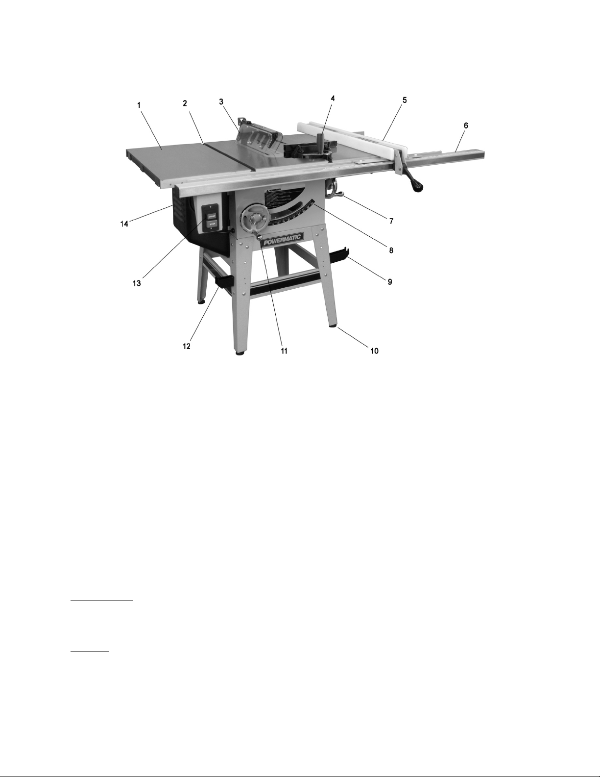
6.0 Features
Figure 1
1 – Cast iron table extensions
2 – T-slots
3 – Transparent blade guard with riving knife
4 – Precision miter gauge with extension face
5 – Accu-Fence®
6 – Rail set (30” shown)
7 – Blade tilt handwheel (with lock knob)
8 – Blade tilt angle scale
9 – Accu-Fence storage hook
10 – Adjustable foot pads
11 – Blade elevation handwheel (with lock knob)
12 – Miter gauge storage hook
13 – Industrial style push button switch
14 – Motor cover
7.0 Specifications
Model number .................................................................................................................................................... 64B
Stock Numbers:
Model 64B basic saw – with stand, no fence or rails ................................................................................. 1791229
Model 64B basic saw – with 30” Rail Set, Accu-Fence
Model 64B basic saw – with 50” Rail Set, Accu-Fence
Materials:
Stand ............................................................................................................................................................. steel
Saw body ....................................................................................................................................................... steel
Tables........................................................................................................................................... ground cast iron
Handwheels ............................................................................................................................................. cast iron
Trunn ion ...................................................................................................................... ............................ cas t iron
Fence body ................................................................................................................. steel with HDPE side plates
®
, 27”x17” Wood Extension Table .........................1791229K
®
, 27”x36” Wood Extension Table, Legs ................1791230K
8
Page 9

Motor an d Electrical s:
Motor type .............................................................................. totally enclosed fan cooled, induction, capacitor start
Horsepower ............................................................................................................................... 1-3/4 HP (1.3 kW)
Phase .......................................................................................................................................................... sing le
Volta ge ....................................................................................................................... .. 115/230V (prewired 115V)
Cycle ........................................................................................................................................................... 60 Hz
Motor speed .......................................................................................................................................... 3450 RPM
Listed FLA (full load amps) ....................................................................................................................... 1 5/7 .5 A
Starting a mp s .................................................................................................................................................. 52A
Running amps (no load) .................................................................................................................................... 6A
Start capacitor ............................................................................................................................ 400MFD 125VAC
Run capacitor ....................................................................................................................................... 30μF 250V
Power transfer ............................................................................................................................................... v-belt
On/of f s witch ........................................................................................... manual industrial-style, with padlock hole
Power cord length .............................................................................................................................. 7 ft. (213cm)
Power plug installed ......................................................................................................................................... yes
Recommended circuit size
1
................................................................................... 30A (for 115V) or 20A (for 230V)
Noise emission:
Without loa d ........................................................................................................ 78 dB at 20 inches from blade
With load ............................................................................................................. 85 dB at 20 inches from blade
Arbor and blade:
Blade Diamet er2 (in.) ........................................................................................................................ ..10” (254mm)
Arbor Diameter (in.) .............................................................................................................................5/8” (16mm)
Arbor speed .......................................................................................................................................... 3800 RPM
Arbor lo c k ........................................................................................................................................................ yes
Maximum cut depth at 90 degrees ................................................................................................... 3 -1 /8” (79 mm)
Maximum cut depth at 45 degrees ................................................................................................... 2 -1 /8” (54 mm)
Max imum rip to right o f b la d e ................................................................................... 30” (7 6 2mm) or 50” (1270mm)
Max imum rip to left of b la d e ................................................................................................................12” (305 mm)
Dado maximum width .................................................................................................................... 13/16” (20.7mm
Dado maximum diameter ..................................................................................................................... 8” (20 0mm )
Blade height per one revolution of handwheel .......................................... 5/32” (4mm) for 90°; 1/8” (2.9mm) for 45°
Blade tilt .............................................................................................................................................. left, 0 to 45°
Table:
Table working surface ......................................................................................... 20-1/8” L x 27” W (511 x 686mm)
Table working surface, with extensions .............................................................. 44-1/4” L x 27” W (1124 x 686mm)
Table working surface, with extensions and optional wood table:
With 30” rip capacity ..................................................................................... 71-1/4” L x 27” W (1810 x 686mm)
With 50” rip capacity ..................................................................................... 79-5/8” L x 27” W (2022 x 686mm)
Table area in front of blade at maximum height ............................................................................. 11-1/2” (292mm)
Table heigh t from floor ........................................................................................................................36 ” (9 1 4mm)
Miter s lot .................................................................................................. tw o T-sl ots, 3/4" W x 3/8” D ( 19 x 10mm)
Edge bevel ..................................................................................................................................................... fron t
Dust collection:
Dust po rt outs id e dia meter ................................................................................................................... 4” (100m m)
Minimum extraction volume required .......................................................................................... 350 cfm (9.9 cmm)
Other:
Stand style .....................................................................................................................................................open
Stand footpr int ........................................................................................................ 21-1/2”L x24”W (546 x 610mm)
Overall Dimensions, shipping carton (basic saw only) .......................... 39” L x 25” W x 22” H (98.6 x 63.6 x 56.4cm)
Overall Dimensions, fully assembled, accessories mounted:
With 30” rip capacity ................................................................... 71-1/4” L x 43” W x 42” H (181 x 109 x 107cm)
With 50” rip capacity ................................................................... 79-5/8” L x 43” W x 42” H (202 x 109 x 107cm)
Weights:
Net................................................................................................................................................. 293 lb (133 kg)
Shipping......................................................................................................................................... 304 lb (138 kg)
1
subject to local and national electrical codes.
2
blade not included.
9
Page 10

8.0 Setup and Assembly
8.1 Shipping contents
(Figures 2 through 7)
1 Saw body with switch – A
2 Cast iron table extensions – B
1 Motor cover – C
2 Handwheels – D
2 Handwheel locking knobs – E
2 Handles – F
1 Arbor wrench – G
2 Open end wrenches (14-17, 10-12mm) – H
4 Hex keys (2.5/3/4/6mm) – I
1 Blade guard with anti-kickback pawls – J
1 Riving knife – K
1 Low profile riving knife – L
1 Miter gauge – M
1 Push stick – N
1 Table insert – O
1 Hardware package (p/n 64B-HP):
6 Hex cap screws M10x30 – HP-1
6 Lock washers 10mm – HP-2
6 Flat washers 10mm – HP-3
1 Stand assembly:
1 Upper brace, with cutout – P
1 Upper brace, long – Q
2 Upper braces, short – R
2 Lower braces, long – S
2 Lower braces, short – T
4 Legs – U
4 Foot pads – V
2 Fence hooks – W
1 Miter gauge hook – X
1 Small hook – Y
1 Stand hardware package (p/n 64B-SHP)
4 Hex cap screws M8x25 – SHP-1
8 Pan head screws M5x15 – SHP-2
24 Carriage bolts M8x16 – SHP-3
40 Flat washers 8mm – SHP-4
28 Lock washers 8mm – SHP-5
36 Hex nuts M8– SHP-6
8 Hex nuts M5 – SHP-7
1 Instructions and Parts Manual
1 Warranty Card
NOTE: The Accu-Fence, rail set, optional wood
extension table and legs, are all packaged
separately and supplied with their own hardware.
Figure 2
Figure 3
Figure 4 – Hardware package (64B-HP)
Figure 5 – Stand assembly
10
Page 11

Figure 6
Figure 7 – Stand hardware package (64B-SHP)
8.2 Unpacking and cleanup
Open shipping container and check for shipping
damage. Report any damage immediately to your
distributor and shipping agent. Do not discard any
shipping material until the Table Saw is assembled
and running properly.
Compare the contents of your container with the
previous list to make sure all parts are intact.
Missing parts, if any, should be reported to your
distributor. Read the instruction manual thoroughly
for assembly, maintenance and safety ins tructions.
Tools required for assembly (provided):
10, 12, 14 and 17 mm wrenches
Hex key set
Arbor wrench
Additional tools required (not supplied):
Cross point screwdriver
Rubber mallet or dead-blow hammer (or steel
hammer over a block of wood)
11
Page 12

8.3 Stand assembly
Assembly tip: A ratchet wrench with sockets and
extensions will speed assembly time.
1. Assemble stand, using Figure 8 as a guide.
Use the provided carriage bolts, flat washers
lock washers, and hex nuts (SHP-3/4/5/6).
Only make fasteners snug at this time. They
will be fully tightened later, after stand has
settled under the weight of the saw.
2. Note the or ientation of the c ut-out brace (P) to
the front brace with Powermatic label (R). The
cut-out brace must be to the left, to allow
protrusion of the motor.
3. When stand has been assembled, turn it over
and install the rubber foot pads (V). (Should
you ever need height adjustment on the foot
pad, loosen the two hex nuts, rotate t he pad,
then retighten the hex nuts against the metal
of the stand.)
4. Turn stand right-side up. The fasteners are not
fully tight, but they should be snug enough to
withstand the weight of the saw. If the stand
needs more stability, snug fasteners a little
more.
5. The four large holes on top of the stand should
be reasonably aligned through the upper
braces for easy insertion of the screws.
Figure 8
12
Page 13

Figure 9
8.4 Mounting saw to stand
Refer to Figure 9
The table saw is heavy! Get
persons to assist you in lifting it. Failure to
comply may result in serious personal injury
and/or damage to the machine.
1. Carefully lift table saw out of carton.
2. Place table saw atop the stand, orienting the
motor in the cut-out of the stand, and aligning
the four holes on its bottom edge with those in
the stand.
3. Insert four screws, with flat washers, lock
washers and hex nuts (SHP-1/4/5/6), as
shown.
4. Securely tighten all four hex nuts (SHP-6),
using a 12mm wrench and an additional
wrench to hold the screw steady while
tightening the nut. (NOTE: If you need more
room to wrench the back screws, follow
instructions below for tilting motor out of the
way.)
5. Finish tightening all fasteners in the stand.
8.5 Installing handwheels/hooks
Refer to Figure 9.
1. Install a handwheel onto the tilting and raising
shafts, as shown. Fit the slot of the handwheel
onto the roll pin on the shaft, then secure by
screwing on the locking knob.
2. Inst al l a hand le ont o ea ch ha ndwhe el , u si ng a
14mm wrench on the flat to tighten it.
3. Install hooks (W and X) with two screws and
hex nuts (SHP-2/7). Placement is personal
preference, as all legs have holes for them.
NOTE: The two larger hooks will be on the
same side, to hold the fence. The smaller hook
holds the miter gauge.
4. Mount small hook (Y) to the front, to hold
additional accessories such as arbor wrench,
push stick, rivin g knife, etc.
5. Tilt arbor using right handwheel, and remove
Styrofoam packing from above motor.
13
Page 14

8.6 Installing table extensions
Refer to Figure 10.
Figure 10
1. Attach a table extension to the saw table.
Make sure edge bevel on table extension
faces front, to match that of saw table. Use
three screws, lock washers and flat washers
(HP-1/2/3). Lightly snug screws with 17mm
wrench.
Assembly Tip: If you are doing this without an
assistant, lift table extension vertically to the
table edge. Install center screw and washer,
and make snug. Then pivot the extension
parallel to saw table to insert the other two
screws.
2. Repeat for opposite table extension. Lightly
snug screws.
3. The front edge of table extensions must be
flush with front edge of saw table. If needed,
tap front edge of extension with a rubber
mallet to make flush. See Figure 11.
1. Start by tightening the three screws (17mm
wrench) under the table extension that secure
it to the saw table. Tighten these just enough
to hold the extension in place but loose
enough to change the extension height by
tapping on it.
2. Lay the straight edge (A, Figure 12) across t he
saw table and extension, extending it out past
the edge of the extension as shown.
3. Mo ve the st r a ight edg e t o severa l place s along
the t able ext ensi on, a s yo u co nti nue to nudg e
the extension level with the saw table. When
extension is level with saw table, securely
tighten each of the three screws.
4. Repeat steps 1 through 3 for opposite table
extension.
Figure 12
8.8 Rails an d Fence
With table extensions properly aligned, the rails
and Accu-Fence® asse mbly c an now be m ounted
to the saw. Consult the manual, no. M-2195075Z,
that accompanies the fence.
NOTE: The two tapped holes at the ends of the
table extensions are not used. There may be
additional holes in the table’s edge that are not
required for this rail installation.
Figure 11
8.7 Leveling table extensions
Refer to Figure 12.
Level table extensions to saw table using a straight
edge. A metal straight edge is ideal, though a
carefully jointed board may also be used.
8.9 Wood Extension Table
For instructions on mounting the accessory wood
extension table, consult your Accu-Fence®
manual, document no. M-2195075Z.
14
Page 15

8.10 Switch bracket
Refer to Figure 13.
Remove existing screw and washers from the
farthest left hole on the guide tube, and use them
to secure the control switch to bottom of guide
tube, as shown in Figure 13 (10mm wrench).
between table and table insert, slightly raise that
area of the table insert above main table surface.
Figure 13
8.11 Motor cover
Refer to Figure 14.
1. At the motor side, slide the hinge pins of the
motor cover down into the cylinders.
2. To secure cover, loosen knob (B), and swing
cover shut, while pushing in on the side. The
slot (C) should slide beneath the knob.
3. Tighten knob (B).
Figure 15
8.13 Installing and removing blade
A blade is not provided with the 64B.
1. Using front handwheel, raise blade arbor fully
and tighten lock knob.
Refer to Figures 16 and 17.
2. Remove nut (A) and flange (B), and install
blade onto arbor, making sure the teet h point
downward toward front of saw.
3. Install flange (B) and nut (A).
4. Rotate arbor until hole (C, Figure 17) aligns
with arbor lock pin (D). Push tab (E) to seat pin
into hole, and hold to prevent blade rotation.
5. Tighten nut (A) with arbor wrench.
6. Release arbor lock (E).
Figure 14
8.12 Table insert
Refer to Figure 15.
Place insert into table opening (the finger hole is
toward front of saw). Verify that insert lies flush
with table surface by resting a straight edge acro ss
it at var ious points. If insert is not flush a long it s
length, turn any of six set screws (D) to raise or
lower that area of the insert.
NOTE: If while lowering blade, the points on the
anti-kickback pawls tend to catch in the seam
Figure 16
15
Page 16

Figure 17
2. Push guard down so that the pins slide into the
slots in the riving knife, then pull guard
backward to seat.
3. Secure with top latch (K).
4. The transparent guard leaves (L) should drop
freely to the table.
5. Lift the latch (J) to free t he pawls. Pawls must
be lowered into operating position before using
the saw!
9.0 Electrical connections
8.14 Riving knife
Refer to Figure 18.
The saw is supplied with two riving knives: One
extends above the blade and accepts the blade
guard; the other is a low-profile knife that acts
alone for non-through cutting.
To install a riving knife:
1. Remove table insert, and raise arbor all the
way u p.
2. Slide prongs of riving knife into slot between
block (F, Figure 18) and plate (G), and push
riving knife down as far as it will go.
3. Push lever (H) downward, toward blade, until
tight.
4. The riving knife must be parallel to saw blade.
See section 10.5.
Electrical connections must
be made by a qualified electrician in
compliance with all relevant codes. This
machine must be properly grounded to help
prevent electrical shock and possible fatal
injury.
The 64B table saw is rated at 115/230V power, and
is pre-wired for 115 volt. T he table saw com es with
a plug designed for use on a circuit with a
grounded outlet that looks like the one pictured in
A, Figure 19.
Before connecting to power source, be sure switch
is in off position.
It is recommended that the table saw, when
operated on 115 volt power, be connected to a
dedicated 30 amp circuit with a 30 amp circuit
breaker or time-delay fuse marked “D”. When
operated on 230 volt power, it is recommended
that the table saw be connected to a dedicated 20
amp circuit with a 20 amp circuit breaker or t imedelay fuse marked “D”. Local codes take
precedence over recommendations.
9.1 Grounding instructions
Figure 18
8.15 Blade guard
Refer to Figure 18.
1. Lift the anti-kickback pawls (I) and secure
them with the latch (J).
1. All Grounded, Cord-connected Tools:
In the event of a malfunction or breakdown,
grounding provides a path of least resistance for
electric current to reduce t he risk of electr ic shock.
This tool is equipped with an electric cord having
an equipment-grounding conductor and a
grounding plug. The plug must be inserted into a
matching outlet that is properly installed and
grounded in accordance with all local codes and
ordinances.
Do not modify the plug provided - if it will not fit the
outlet, have the proper outlet installed by a
qualified electrician.
Improper connection of the equipment-grounding
conductor can result in a risk of electric shock. The
cond uctor with insulation having an outer surf ace
that is green with or without yellow stripes is the
equipment-grounding conductor.
16
Page 17

If repair or replacement of the electric cord or plug
is necessary, do not connect the equipmentgrounding conductor to a live terminal.
Use only 3-wire extension cords that have 3-prong
grounding plugs and 3-pole receptacles that accept
the tool's plug.
Repair or replace damaged or worn cord
immediately.
Figure 19
2. Grounded, cord-connected tools intended for
use on a supply circuit having a nominal rating less
than 150 volts:
This tool is intended for use on a circuit that has an
outlet that looks like the one illustrated in A, Figure
19. An adapter, shown in B and C, may be used to
connect this plug to a 2-pole receptacle as shown
in B if a properly grounded outlet is not available.
The temporary adapter should be used only unt il a
properly grounded outlet can be installed by a
qualified electrician. This adapter is not permitted
in Canada. The green-colored rigid ear, lug, and
the like, extending from the adapter must be
connected to a permanent ground such as a
properly grounded outlet box.
3. Grounded, cord-connected tools intended for
use on a supply circuit having a nominal rating
between 150 - 250 volts, inclusive:
This tool is intended for use on a circuit that has an
outlet that looks like the one illustrated in D, Figure
19. The tool has a grounding plug that looks like
the plug illustrated in D. Make sure the tool is
connected to an outlet having the same
configuration as the plug. No adapter is available
or should be used with this tool. If the tool must be
reconnected for use on a diff erent type of electric
circuit, the reconnection should be made by
qualified service personnel; and after reconnection,
the tool should comply with all local codes and
ordinances.
Check with a qualified
electrician or service personnel if the
grounding instructions are not completely
understood, or if in doubt as to whether the
tool is properly grounded. Failure to comply
may cause serious or fatal injury.
9.2 Voltage conversion
If230Vsinglephaseoperationisdesired,follow
theseinstructions:
1. Disconnect table saw from power source.
2. Open the motor junction box, and consult the
diagram on the inside of the junction box
cover. Similar diagrams are shown in section
17.0.
NOTE: In case of discrepancy, the junction
box label takes precedence.
3. The four motor leads are connected for 115V
operation; reconnect these leads for 230V
operation, as shown in the diagrams.
4. The 115 volt attachment plug, supplied with
the saw, must be replaced with a UL/CSA
listed plug suitable for 230 volt operation.
Consult an electrician for proper procedures to
install the plug. The saw must comply with all
local and national codes after the 230 volt plug
is inst alled.
In all cases (115V or 230V) make certain the
receptacle in question is properly gr ounded. If
you are not sure, ha ve a registered electricia n
check the receptacle.
9.3 Extension cords
USE PROPER EXTENSION CORD. Make sure
your extension cord is in good condition. When
using an extension cord, be sure to use one heavy
enough to carry the current your product will draw.
An undersized cord will cause a drop in line volta ge
resulting in loss of power and overheating. Table 1
shows correct size to use depending on cord
length and nameplate ampere rating. If in doubt,
use the next heavier gauge. The smaller the gauge
number, the heavier the cord.
Ampere
Rating
More
Than
00 06 18 16 16 14
06 10 18 16 14 12
10 12 16 16 14 12
12 16 14 12
Not
More
Than
Volts
120
240
AWG
Extension Cord Recommendations
Total length of
cord in feet
25
50
50
100
Table 1
100
200
Not
Recommended
150
300
17
Page 18

9.4 Switch lockout
The table saw is equipped with a push-button
switch that will accept a safety padlock, as shown
in Figure 20. To safeguard your machine from
unauthorized operation and accidental starting by
young children, the use of a padlock (not included)
is highly recommended. Place t he key i n a locatio n
that is inaccessible to children and others not
qualified to use the tool.
Figure 20: Switch Lock Out
10.0 Adjustments
10.1 Fence alignment
Before using the Accu-Fence®, verify that it is
properly aligned with the blade. Consult the
manual, no. M-2195075Z, that accompanied the
fence.
10.2 Blade raising/tilt mechanism
Do not try to force tilting
mechanism past the 45º or 90º stops. T his may
cause blade to go out of alignment.
Refer to Figure 21:
To raise or lower blade, loosen lock knob (A) a nd
turn handwheel (B) on front of saw until desired
height is reached. Tighten lock knob. The blade
should be adjusted about 1/8" above top surface of
material being cut.
To tilt blade, turn lock knob (C) counter-clockwise
to loosen, turn handwheel (D) until desired angle is
obtained, and retighten lock knob (C).
10.3 Miter gauge
Refer to Figure 22.
10.3.1 Setting miter angle
The precision miter gauge has a rack and pinion
adjustment for setting the angle. To operate:
1. Slide miter gauge into one of the slots on table
top.
2. Loosen lock handle (A, Figure 22) by turning
counterclockwise.
3. Pull out spring-loaded knob (C) and rotate
knob until body (B) of miter gauge is at the
desired angle as indicated on the scale.
4. Tighten lock handle (A).
10.3.2 Indent settings
There are indents at the 0º, 30º and 45º right and
left positions. At these settings, release knob (C) to
engage stop rod. Then tighten lock handle (A).
Note: Do not rely solely on the indents for an
accurate setting. After the stop rod engages at the
0º, 30º and 45º positions, make a fine adjustment
with the knob (C) if necessary, setting it against the
scale indicator (G).
10.3.3 Extension plate
The extension plate (D, F igure 22) ca n be adjusted
by sliding to the right or left or removed entirely.
To adjust, loosen two lock handles (E), position the
extension plate and retighten lock handles. Make
sure end of extension plate is not in the blade’s
path.
NOTE: The lock handles (E) are adjustable. Pull
out on a handle, rotate it to different position, then
relea se , m a k ing s ure it se a ts itse lf upon the p i n.
To rem ove exte nsion plate , slide it completely off
and remove lock handles (E) and mounting
hardware.
10.3.4 Calibration
1. Place miter gauge in one of the slots on the
table top.
2. Set miter gauge at 90º to blade (0º setting on
the scale) by loosening lock handle (A), then
pulling out spring-loaded knob (C) and turning
the body (B) until 0º is indicated on scale.
3. Measure the accuracy of the gauge against
the slot with a combination square.
If adjustment is necessary:
Figure 21
4. Adjust body (B) until it i s perf ec tly square (90º)
to miter slot.
5. Tighten lock handle (A).
6. Verify that scale indicator (G) reads 0º. If
fur t he r ad jus t ment i s neede d :
18
Page 19

7. Loosen screw (F) and adj ust indicator (G) until
it reads 0º.
8. Tighten screw (F).
NOTE: The bar of the miter gauge has two slots
with set screws (H). Adjust these set screws (4mm
hex key) to eliminate any play between bar and
miter slot.
Figure 22
10.4 Positive blade stops
Figure 23
10.4.2 45° Blade stop
Repeat steps 1 through 4 above for 45° setting, as
shown in Figure 24. The 45° stop is shown at C,
Figure 25.
The stops for 90°, 45° blade tilt, and elevation
settings have all been factory set, and should
require no immediate adjustment. The settings
should be confirmed by the operator, however, and
especially if cuts become inaccurate.
10.4.1 90° Blade stop
1. Disconnect machine from power source.
2. Make sure table insert has been leveled with
table surface. See section 8.12.
3. Raise blade all the way, and place a 90°
square on the table and against the blade
(Figure 23). Make sure t hat a blade toot h does
not obstruct the actual reading.
4. Tilt blade with handwheel as needed until
square and blade are flush.
5. If adjustment is required, loosen the two
setscrews on 90° stop collar (A, Figure 25 –
3mm hex key) and rotate collar along the lead
screw to needed position. Verify the new
setting.
6. Loosen screw on pointer (B, Figure 25), and
adjust pointer to zero. Retighten screw.
Figure 24
Figure 25
10.4.3 Blade elevation stops
Lower blade all the way; it should drop completely
below the table surface. If it does not, adjust
amount of drop using two stop screws (D, Figure
26).
19
Page 20

Figure 26
Figure 28
10.5 Riving knife alignment
The riving knife m ust be aligned with the blade for
proper and safe operation of the table saw. This
has been set by the manufacturer, b ut should be
verified by the operator.
1. Disconnect machine from power source.
2. Install riving knife and tighten le ver (H, Figure
18).
3. Place a straig ht edge against blade and riv ing
knife; it should lie flush against both surfaces.
See Figure 27.
4. If correction is needed, remove straight edge,
table insert, and riving knife and locate four set
screws (E, Figure 28) through the corner holes
of clamp block.
5. Rotate any of the four set screws as needed to
tilt the angle of the clamp block, and thus the
riving kni fe.
6. Install riving knife and verify the setting with
the straight edge. Make furt her adjustm ents as
needed.
10.6 Low profile riving knife
A low prof ile riv ing k nif e is inc lude d wit h yo ur saw.
It mounts and adjusts in the same manner as the
standard riving knife. The low profile riving knife
sits just below top of blade and is used for making
non- through c uts. The blade guard is not used with
this knife, so extra precautions should be taken
during operation.
10.7 Trunnion adjustment
If backlash develops in the trunnion assembly, it
can be adjusted out using the screws (6mm hex
key) at front and back of cabinet (F, Figure 25
shows front screw). Front and rear trunnions
should receive the same amount of spring tension
from the screws.
10.8 Table to blade alignment
Refer to Figures 29 and 30.
The table has been squared to the blade by the
ma nuf ac t ure r a nd no adj us tm e nt is nec e s sar y now .
If cuts become inaccurate, check table-blade
squareness and correct if necessary. Use the miter
slot to do this:
Figure 27
1. Disconne ct saw from power s ource.
2. Raise blade to maximum height.
3. Mark one tooth (A, Figure 29) with a grease
pencil and position the tooth slightly above t he
top edge of table at the front.
4. Raise the miter gauge slightly out of its slot to
serve as a shoulder. Using a sliding square (B)
against the side of the bar, slide the scale over
until it touches the tip of the blade, and lock
the scale in position.
20
Page 21

Figure 29
1. Loosen screw (A) and hex nut (B) and pivot
motor upward to release tension on belt. If
greater movement is needed, remove screw
(A) and pivot motor further.
2. Replace belt.
3. Reinstall screw (A) and push down on motor to
tension new belt.
4. Tighten screw (A) and hex nut (B).
Figure 31
Figure 30
5. Rotate marked tooth (A) so that it is slightly
above table top at the rear and, using the
square as before, verify that the distance to
the blade is the same. See Figure 30. If the
distances are not the same, make a careful
note of the difference.
6. Loosen table screws (item #30, section
16.1.1), and nudge table according to the
distance you noted.
7. Retighten screws firmly.
8. Verify the alignment, angle pointer setting,
fence setting, etc. Make any needed
adjustments.
10.9 Belt tension and replacement
Tension of the drive belt should be inspected after
the first few days of operation, as it may stretch
slight l y d uri ng in it ial use; al so in spe ct it pe rio d ical l y
thereafter.
To tighten belt:
1. Disconnect machine from power source.
2. Loosen screw (A, Figure 31) and hex nut (B,
Figure 31).
3. Press down on motor while retightening screw
(A) and hex nut (B).
If belt shows signs of wear, fraying, cracks, etc. it
should be replaced:
11.0 Operations
NOTE: If the saw is to be used without the metal
stand provided, care must be taken to provide a
hole in the stand or bench used by the operator to
facilitate removal of sawdust.
If there is any tendency to
slide, walk, or tip over during operation, the
stand or bench MUST be secured to the floor.
Familiarize yourself with the location and operation
of all controls and adjustments and the use of
accessories such as miter gauge and rip fence.
11.1 Start/st op switch
This table saw has a manual
switch. If the power goes out during oper ation,
push the STOP button. Otherwise, the saw will
start up when power is restored.
11.2 Kickback prevention
Serious injury can result from kickbacks which
occur when a workpiece binds on the saw blade or
binds between the blade and rip fence or other
fixed object. This binding can cause the workpiece
to lift up and be thrown toward the operator.
Listed below are conditions which can cause
kickbacks:
Confining the cutoff piece when
crosscutting or ripping.
21
Page 22

Releasing the workpiece before
completing operation or not pushing work
piece all the way past saw blade.
Not using the splitter/riving knife when
ripping or not maintaining alignment of the
splitter/riving knife with the saw blade.
Using a dull saw blade.
Not maintaining alignment of the rip fence
so that it tends to angle toward rather than
away from the saw blade front to back.
Applying feed force when ripping to the
cutoff (free) section of the workpiece
instead of the section between saw blade
and fence.
Ripping wood that is twisted (not flat), or
does not have a straight edge, or has
twisted grain.
To minimize or prevent injury from kickbacks:
Avoid conditions listed above.
Wear a safety face shield, goggles, or
glasses.
Do not use the miter gauge and rip fence
in the same operation unless provision is
made by use of a facing board on the
fence so as to allow the cutoff section of
the workpiece to come free before the
actual cut begins (See Figure 39).
As the machine receives use, the
operation of the anti-kickback pawls
should be checked periodically (Figure
32). If the pawls do not stop the reverse
motion of a workpiece, resharpen all the
points.
narrow (6" width or less), or thin work. Use
a push block or miter gauge hold-down
when dadoing or molding.
Never use the fence as a length stop
when crosscutting. Do not hold or touch
the free end or cutoff section of a
workpiece. On through-sawing operations,
the cutoff section must NOT be confined.
Always keep your hands out of line of the
saw blade and never reach back of the
cutting blade with either hand to hold the
workpiece.
Bevel ripping cuts should always be made
with the fence on the right side of saw
blade so that the blade tilts away from the
fence and minimizes the possibility of the
work binding and the resulting kickback.
11.3 Rip sawing
Ripping is where the workpiece is fed with the grain
into the saw blade using the fence or other
positioning device as a guide to ensure desired
width of cut (Figure 33).
Before starting a ripping cut,
verify that fence is clamped securely and
aligned properly.
Never rip freehand or use miter gauge in
combination with the fenc e.
Never rip workpieces shorter than the saw
blade diameter.
Never reach behind the blade with either
hand to hold down or remove the cutoff
piece with the saw blade rotating.
Figure 32
Where possi ble, keep your face and body
out of line with potential kickbacks
including when starting or stopping the
machine.
Dull, badly set, improper, or improperly
filed cutting tools, and cutting tools with
gum or resin adhering to them can cause
accidents. Never use a cracked saw
blade. The use of a sharp, well
maintained, and correct cu tting tool for the
operation will help avoid injuries.
Support the work properly and hold it
firmly against gauge or fence. Use a push
stick or push block when ripping short,
Figure 33
Always use blade guard, splitter/riving knife and
anti-kickback pawls. Make sure splitter/riving knife
is properly aligned. When wood is cut along the
grain, the kerf tends to close and bind on the blade
and kickbacks can occur.
22
Page 23

Figure 34
The rip fence (A, Fig. 34) should be set for the
width of the cut by using the scale on the front rail,
or by measuring the distance between blade (A)
and fence (B). Stand out of line with saw blade and
workpiece to avoid sawdust and splinters coming
off the blade or a potential kickback.
If the work piece does not have a straight edge,
nail an auxiliary straight edged board on it to
provide one against the fence. To cut proper ly, the
board must make good contact with the table. If it
is slightly warped, turn the hollow side down. Do
not attempt to cut boards with significant warp.
In ripping, use one hand to hold the board down
against the fence or fixture, and the other to push it
into the blade between blade and fence. If
workpiece is narrower than 6" or shorter than 12",
use a push stick or push block to p ush it through
between fence and blade (Figure 35). Never push
in a location such that the pushing hand is in line
with the blade. Move the hand serv ing as a holddown a safe distance from blade as cut nears
completion.
For very narrow ripping where a push stick ca nnot
be used, use a push block or auxiliary fence.
Always push the workpiece completely past the
blade at the end of a cut to minimize the possibility
of a kickback.
Figure 36
When ripping long boards, use a support at front of
table (C, Figure 36), such as a roller stand, and a
support or "tailman" at the rear (D).
Never use the rip fence beyond the point where the
carriage is flush with the end of the rails.
Have the blade extend about 1/8" above the top of
the workpiece. Exposing the blade above this po int
can be hazardous.
11.4 Resawing
Resawing is a ripping operation in which thick
boards are cut into thinner ones. Note: A band saw
is the ideal tool for resawing.
If the table saw is used for
resawing, take precautions such as using an
auxiliary fence, resaw barrier or similar devices
to stabilize the workpiece and provide operator
safety.
Narrow boards up to 3" can be resawn in one pass.
Wider boards up to 6" must be resawn in two
passes.
In resawing wider boards, adjust the blade height
so as to overlap the two cuts by 1/2" as shown in
Figure 37. Too deep a first cut can result in binding
and possible kickbacks on the second cut. Always
use the same side of the board against the fence
for both cuts.
Figure 35
23
Page 24

Figure 37
11.5 Crosscutting
Crosscutting is where the workpiece is fed cross
grain into the saw blade using the miter gauge to
support and position the workpiece (Figure 38).
Do not crosscut workpieces shorter than 6". Before
starting a cut, be sure the miter gauge is securely
clamped at the desired angle. Hold the workpiece
firmly against the table and back against the miter
gauge. Always use the saw guard and riving knife
and make sure the riving knife is properly aligned.
For 90 degree crosscutting, most operators prefer
to use the left-hand miter gauge slot. When using it
in this position, hold the workpiece against the
gauge with the left hand and use the right hand to
advance the workpiece. When using the right hand
slot for miter and compound crosscutting so that
the blade tilts away from the gauge, the hand
positions are reversed.
When using the miter gauge, the workpiece must
be held firmly and advanced smoothly at a slow
rate. If the workpiece is not held firmly, it can
vibrate causing it to bind on the blade and dull the
saw teeth.
Figure 38
Crosscutting should never be done freehand nor
should the fence be used as an end stop unless an
auxiliary block (E, Figure 39) is clamped to the
front of the blade area such that the cutoff piece
comes free of the block before cutting begins.
Figure 39
Length stops should not be used on the free end of
the workpiece in the cutoff area.
To augment the effectiveness of the miter gauge in
crosscutting, some users mount an auxiliary
wooden extension face (F, Figure 40) with a gl uedon strip of sandpaper (G) to the miter gauge.
Provide auxiliary support for any workpiece
extending beyond the table top with a tendency to
sag and lift up off the table.
Have the blade extend about 1/8" above the top of
the workpiece. Exposing the blade above this po int
can be hazardous.
Figure 40
11.6 Bevel and miter operations
Bevel cut – A bevel cut is a special type of
operation where the saw blade is tilted at a n angle
less than 90 degrees to the table top (Figure 41).
Operations are performed in the same manner as
ripping or crosscutting, except the fence or miter
gauge should be used on the right-hand side of the
blade to provide added safety in avoiding a binding
action between blade and table top. When beveling
with the miter gauge, the workpiece must be held
firmly to prevent creeping.
24
Page 25

Figure 41
Mitering – Crosscuts made at an angle to the edge
of the workpiece are cal led miters (Figure 42). Set
the miter gauge at the required angle, and make
the cut the same as a normal crosscut except the
workpiece must be held extra firmly to prevent
creeping.
The process of cutting 1/8" to 13/16" grooves in
workpieces is accomplished by the use of a
stacked dado blade set or an adjustable type blade
mounted on the saw arbor. By using various
combinations of stacked dado blades, or properly
setting the dial on an adjustable blade, an accurate
width dado can be made. This is very useful for
shelving, making joints, tenoning, etc.
The guard, riving knife, and anti-kickback pawls
supplied with the saw should be used for all cutting
operations where they can be used. When
performing operations where the guard cannot be
used, as in some dadoing operations, alternative
safety precautions should be taken. These include
push sticks, feather boards, filler pieces, fixtures,
jigs and any other appropr iate device that can be
utilized to keep operators’ hands away from the
blade. Upon completion of t he operation requiri ng
removal of the guard, the entire guard assembly
must be placed back on the machine in its proper
working order.
Never use a dado head in a
tilted position. Never operate the saw without
the blade guard, riving knife and anti-kickback
pawls for operations where they can be used.
Figure 42
Note: When making compound miters (with blade
tilted) use the miter gauge in the right ha nd s lot to
provide more hand clearance and safety.
Have the blade extend only 1/8" above the top of
the workpiece. Exposing the blade above this po int
can be hazardous.
11.7 Dado cutting
Dadoing is cutting a wide groove into a workpiece
or cutting a rabbet alo ng the edge of a workpiece.
A dado insert (optional accessory, not provided)
shown in Figure 43, is necessary for this type of
operation.
Do not use the sta ndard table
insert for dadoing operations.
Figure 43
25
Page 26

12.0 Safety devices
Feather board
Feather boards can be purchased at most tool
stores, or made by the operator to suit particular
applications. The feather board (Figure 44) should
be made of straight grain hardwood appro ximately
1" thick and 4" to 8" wide depending on the size of
the machine. The length is developed in
accordance with intended use.
Feather boards can be faste ned to the table or rip
fence by use of C-clamps. Alternatively, drilled and
tapped holes in the table top a llow the use of w ing
nuts and washers as a method of clamping. If this
method of fastening is used, provide slots in the
feather board for adjustment. (The illustration
shows a method of attaching and use of the
feather board as a vertical comb. The horizontal
application is essentially the sam e except that the
attachment is to the table top.)
Figure 45 – Filler Piece
Push stick and push block
The use of a push block or push stick provide s an
added level of safety for the operator. A p ush stick
is included with your table saw, but you may wish
to make others personalized for different cutting
procedures. The templates in Figures 46 and 47
offer construction details.
Figure 44
Filler piece
A filler piece (Figure 45) is necessary for narrow
ripping and permits the blade guard to remain on
the machine. It also provides space for the safe
use of a push stick.
Figure 46 – Push Block Template
26
Page 27

Wipe down table surface and T-slots, and
apply a rust preventive to them.
Clean pitch and resin from saw blade.
Weekly:
Clean motor housing with compressed air.
Wipe down fence rails with a dry silicon
lubricant.
Lubrication
Refer to Figure 48.
Lower the arbor all the way, and lubricate the
following elements with a lithium grease every 12
months, or more frequently if needed. Clean the
elements first with a solvent/degreaser and a soft
rag.
Blade angling trunnions (A, Figure 48).
Wipe a light coat of grease on the
elevating rods (B).
Threads of blade elevating screw (C)
Threads of blade tilting screw (D).
Raise and lower arbor, and tilt it back and forth, to
distribute the grease.
Figure 47 – Push stick template
13.0 Maintenance
Always disconnect power to
the machine before performing maintenance.
Failure to do this may result in serious
personal in jury.
Cleaning
Clean the table saw according to the schedule
below to ensure maximum performance. The
schedule assumes the saw is being used every
day.
Daily:
Check all adjustments after lubricating.
Figure 48
Miscellaneous
Always be aware of the condition of your machi ne.
Routi ne ly check the condition of t he follow i ng it e m s
and repair or replace as necessary:
Mounting bolts (tighten)
Power switch
Saw blade (cracks, worn or dull teeth, etc.)
Blade guard and riving knife
Drive belt (cracks, frays, worn areas, etc.)
27
Page 28

14.0 Optional accessories
These accessory items, purchased separately, can
enhance the functionality of your table saw.
Contact your dealer to order, or cal l Powermatic at
the phone number on the cover.
p/n 1791088 – Dado insert for 64B table saw
p/n 708118 – Universal mobile base
Figure 49
28
Page 29

15.0 Troubleshooting the 64B Table Saw
Table 2
Trouble Probable Cause Remedy
No incoming power. Check all plug connections.
Table saw will not start.
Excessive vibration.
Cuts out-of-square
when crosscutting.
Motor st a lls or
workpiece binds or
burns.
Cuts not true at 90 or 45
degrees.
Tilting or Rais in g
handwheel difficult to
turn.
Motor overheats
Motor starts slowly or
fails to come up to full
speed.
Motor fails to develop
full power.
Fuse blown, or circuit breaker tripped. Replace fuse, or reset circuit breaker.
Cord damaged. Replace cord.
Tilting or raising lock knobs not tightened. Tighten lock knobs on handwheels.
Machine not resting evenly on floor.
Blade out of balance. Replace blade.
Pulle y loose.
Belt is worn, cracked or frayed. Replace belt.
Motor not functioning properly.
Miter gauge out of adjustment.
Miter slot misaligned. Realign table to blade (Section 10.8).
Excessive feed. Reduce feed.
Dull or incorrect blade.
Miter slot misaligned. Realign table to blade (Section 10.8).
Fence misaligned.
Motor malfunction.
Stop screws not set properly. Readjust screws (Section 10.4).
Lock knob not released. Loosen lock knob.
Worm and worm gear segment caked with
sawdust and pitch.
Worm and worm gear segment out of
alignment.
Motor overloaded.
Im proper cool ing of m otor ; lack of air
circulation.
Low voltage.
Centrifugal switch not operating.
Motor malfunction.
Power line overloaded. Correct overload condition.
Undersized wires in supply system. Increase supply wire size.
Low voltage.
Motor malfunction.
Adjust foot pad(s). If saw is secured to
floor, use shi ms as needed.
Check motor pulley and spindle pulley.
Tighten set screws if needed.
Have motor checked by a qualified
inspector. Repair or replace.
Re-set stops and pointer on gauge.
(Section 10.3).
Replace blade; use proper type of blade
for cut needed.
Realign fenc e (see Accu-Fence®
manual).
Have motor checked by a qualified
inspector. Repair or replace.
Clean and regrease worm and worm gear
segment.
Realign worm wi th segment.
Identify and correct overload condition,
e.g. excessive feed rate of stock.
Clean sawdust from fan and duct areas of
motor.
Request voltage check from power
company and correct low voltage
condition.
Replace centrifugal switch (qualified
personnel only).
Have motor checked by a qualified
inspector. Repair or replace.
Request voltage check from power
company and correct low voltage
condition.
Have motor checked by a qualified
inspector. Repair or replace.
16.0 Replacement Parts
Replacement parts are listed on the followi ng pages. To order parts or reach our service departm ent, call 1800-274-6848 Monday through Friday (see our website for business hours, www.powermatic.com). Having the
Model Number and Serial Number of your machine available when you call will allow us to serve you quickly
and accurately.
29
Page 30

16.1.1 Table and Cabinet Assembly – Exploded View
30
Page 31

16.1.2 Table and Cabinet Assembly – Parts List
IndexNo PartNo Description Size Qty
1 ................ 64B-101..................... Table ........................................................................ ...................................... 1
2 ................ 64B-102..................... Table Extension ....................................................... ...................................... 2
.................. 64B-TIA ..................... Table Insert Assembly (#3 thru #4).......................... ...................................... 1
3 ................ 64B-103..................... Table Insert .............................................................. ...................................... 1
4 ................ TS-1522011 .............. Socket Set Screw .................................................... M5x5 ............................. 6
5 ................ 64B-105..................... Cover ....................................................................... ...................................... 1
6 ................ 3520B-126................. Handle ..................................................................... ...................................... 1
7 ................ 64B-107..................... Handwheel ............................................................... ...................................... 1
8 ................ 64B-108..................... Cover Plate .............................................................. ...................................... 1
9 ................ 64B-109..................... Lead Screw .............................................................. ...................................... 1
10 .............. 64B-110..................... Angle Scale.............................................................. ...................................... 1
11 .............. BB-6201ZZ ................ Ball Bearing ............................................................. 6201ZZ.......................... 1
12 .............. 64B-112..................... Cabinet .................................................................... ...................................... 1
13 .............. TS-1523021 .............. Socket Set Screw .................................................... M6x8 ............................. 4
14 .............. TS-1523011 .............. Socket Set Screw .................................................... M6x5 ............................. 4
15 .............. 64B-115..................... Bushing .................................................................... ...................................... 2
16 .............. 64B-116..................... Bushing .................................................................... ...................................... 2
17 .............. 64B-117..................... Spring Pin ................................................................ Ø4x25 mm .................... 1
18 .............. TS-1540061 .............. Hex Nut .................................................................... M8 ................................. 2
19 .............. TS-2361081 .............. Lock Washer ............................................................ M8 ................................. 6
20 .............. TS-1550061 .............. Flat Washer ............................................................. M8 ................................. 6
21 .............. TS-1504071 .............. Socket Head Cap Screw.......................................... M8x35 ........................... 2
22 .............. 64B-122..................... Spring Pin ................................................................ Ø3x12 mm .................... 2
23 .............. 64B-123..................... Lock Bushing ........................................................... ...................................... 1
24 .............. 64B-124..................... Lock Knob ................................................................ ...................................... 1
25 .............. LM000636 ................. Warning Label.......................................................... ...................................... 1
26 .............. 6290630 .................... Strain Relief ............................................................. 7W-2 ............................. 3
27 .............. TS-1550031 .............. Flat Washer ............................................................. M5 ................................. 1
28 .............. 64B-128..................... Lock Knob ................................................................ ...................................... 1
29 .............. 64B-129..................... I.D label.................................................................... ...................................... 1
30 .............. TS-1490031 .............. Hex Cap Screw ........................................................ M8x20 ........................... 4
31 .............. TS-1491041 .............. Hex Cap Screw ........................................................ M10x30 ......................... 6
32 .............. TS-2361101 .............. Lock Washer ............................................................ M10 ............................... 6
33 .............. TS-1550071 .............. Flat Washer ............................................................. M10 ............................... 6
34 .............. 64B-134..................... Power Cord .............................................................. ...................................... 1
35 .............. 64B-135..................... Motor Cord ............................................................... ...................................... 1
36 .............. TS-081C082 .............. Phillips Pan Head Machine Screw ........................... #10-24x1-1/2”................ 2
37 .............. 6296133 .................... Switch Push Button.................................................. ...................................... 1
38 .............. 6291367 .................... Switch Bracket ......................................................... ...................................... 1
39 .............. TS-0733031 .............. Star Washer ............................................................. #10 ................................ 2
40 .............. 6296128 .................... Switch ...................................................................... ...................................... 1
41 .............. 6291366 .................... Switch Box ............................................................... ...................................... 1
42 .............. TS-0560071 .............. Hex Nut .................................................................... #10-24 ........................... 2
43 .............. TS-1533032 .............. Phillips Pan Head Machine Screw ........................... M5x10 ........................... 2
44 .............. TS-0733041 .............. Star Washer ............................................................. 1/4" ................................ 2
45 .............. TS-1540031 .............. Hex Nut .................................................................... M5 ................................. 2
46 .............. TS-0720071 .............. Lock Washer ............................................................ 1/4" ................................ 1
47 .............. TS-0050031 .............. Hex Cap Screw ........................................................ 1/4"-20x3/4” .................. 1
48 .............. JPS10TSR-103 ......... Push Block ............................................................... ...................................... 1
49 .............. 6290642 .................... Arbor Wrench........................................................... ...................................... 1
50 .............. JBOS5-105................ Open End Wrench ................................................... #14-#17 ......................... 1
51 .............. JBOS5-106................ Open End Wrench ................................................... #10-#12 ......................... 1
52 .............. TS-152707 ................ Hex Key ................................................................... 6mm .............................. 1
53 .............. TS-152705 ................ Hex Key ................................................................... 4mm .............................. 1
54 .............. TS-152704 ................ Hex Key ................................................................... 3mm .............................. 1
55 .............. JPS10TSR-105 ......... Hex Key ................................................................... 2.5mm ........................... 1
.................. 64B-HP...................... Hardware Package (includes #31-33) ..................... ...................................... 1
31
Page 32

16.2.1 Motor a n d Trunnion Assembly – Exploded View
32
Page 33

16.2.2 Motor a n d Trunnion Assembly – Parts List
IndexNo PartNo Description Size Qty
1 ................ 64B-124..................... Lock Knob ................................................................ ...................................... 1
2 ................ 3520B-126................. Handle ..................................................................... ...................................... 1
3 ................ 64B-107..................... Handwheel ............................................................... ...................................... 1
4 ................ 64B-117..................... Spring Pin ................................................................ Ø4x25 mm .................... 1
5 ................ 64B-205..................... Lead Screw .............................................................. ...................................... 1
6 ................ 64B-206..................... Thrust Bearing ......................................................... 51104 ............................ 1
7 ................ 64B-207..................... Bushing .................................................................... ...................................... 1
8 ................ TS-154012 ................ Hex Nut .................................................................... M20-2.5P ...................... 1
9 ................ 64B-209..................... Bushing .................................................................... ...................................... 1
10 .............. 64B-210..................... Spacer ..................................................................... ...................................... 1
11 .............. TS-1522031 .............. Socket Set Screw .................................................... M5x10 ........................... 2
12 .............. TS-0267041 .............. Socket Set Screw .................................................... 1/4 ”-20x3/8”................... 4
13 .............. 64B-213..................... Gear ......................................................................... ...................................... 2
14 .............. 64B-214..................... Pointer ..................................................................... ...................................... 1
15 .............. TS-1533052 .............. Phillips Pan Head Machine Screw ........................... M5x15 ........................... 8
16 .............. 64B-216..................... Lock Washer ............................................................ ...................................... 2
17 .............. 64B-217..................... Guide Shaft .............................................................. ...................................... 1
18 .............. TS-1541031 .............. Nylon Lock Hex Nut ................................................. M8 ................................. 1
19 .............. 64B-219..................... Bearing .................................................................... ...................................... 1
20 .............. 64B-220..................... Gear Cover .............................................................. ...................................... 1
21 .............. TS-1532042 .............. Phillips Pan Head Machine Screw ........................... M4x12 ........................... 3
22 .............. TS-1550021 .............. Flat Washer ............................................................. M4 ................................. 3
23 .............. 64B-223..................... Poly-V Belt ............................................................... 188J .............................. 1
24 .............. 64B-224..................... Socket Head Cap Screw.......................................... M8x65 ........................... 1
25 .............. TS-1550061 .............. Flat Washer ............................................................. M8 ................................. 2
26 .............. 64B-226..................... Spring ...................................................................... ...................................... 1
27 .............. 64B-227..................... Trunnion................................................................... ...................................... 2
28 .............. TS-1491031 .............. Hex Cap Screw ........................................................ M10x25 ......................... 4
29 .............. TS-2361101 .............. Lock Washer ............................................................ M10 ............................... 4
30 .............. 64B-230..................... Center Trunnion ....................................................... ...................................... 1
31 .............. 64B-231..................... Screw ....................................................................... ...................................... 1
32 .............. 64B-232..................... Support Base ........................................................... ...................................... 1
33 .............. TS-1482031 .............. Hex Cap Screw ........................................................ M6x16 ........................... 2
34 .............. TS-1550041 .............. Flat Washer ............................................................. M6 ................................. 2
35 .............. 64B-235..................... Cover ....................................................................... ...................................... 1
36 .............. TS-1550031 .............. Flat Washer ............................................................. M5 ................................. 5
37 .............. 6290693 .................... Arbor Nut ................................................................. ...................................... 1
38 .............. 6290598 .................... Flange ...................................................................... ...................................... 1
39 .............. 64B-239..................... Arbor ........................................................................ ...................................... 1
40 .............. 64B-240..................... Clamp ...................................................................... 3” ................................... 2
41 .............. 64B-241..................... Hose ........................................................................ ...................................... 1
42 .............. 64B-242..................... Nut ........................................................................... ...................................... 1
43 .............. 64B-243..................... Lock Handle ............................................................. ...................................... 1
44 .............. 64B-244..................... Bolt........................................................................... ...................................... 1
45 .............. 64B-245..................... Holding Plate ........................................................... ...................................... 1
46 .............. TS-1524011 .............. Socket Set Screw .................................................... M8x8 ............................. 4
47 .............. 64B-247..................... Support Base ........................................................... ...................................... 1
48 .............. 64B-248..................... Low Profile Riving Knife ........................................... ...................................... 1
49 .............. TS-1550041 .............. Flat Washer ............................................................. M6 ................................. 1
50 .............. 64B-250..................... Bolt........................................................................... ...................................... 1
51 .............. 64B-251..................... Spring ...................................................................... ...................................... 1
52 .............. 64B-252..................... Moving Rod.............................................................. ...................................... 2
53 .............. TS-1504041 .............. Socket Head Cap Screw.......................................... M8x20 ........................... 2
54 .............. TS-1504071 .............. Socket Head Cap Screw.......................................... M8x35 ........................... 2
55 .............. 64B-255..................... S-Ring ...................................................................... S15................................ 1
56 .............. 64B-256..................... Bushing .................................................................... ...................................... 2
57 .............. 64B-257..................... Lead Screw .............................................................. ...................................... 1
58 .............. 64B-258..................... Thrust Bearing ......................................................... ...................................... 1
59 .............. 64B-259..................... Ball Bearing ............................................................. 6202-5/8” bor e .............. 2
33
Page 34

IndexNo PartNo Description Size Qty
60 .............. 64B-260..................... Shaft ........................................................................ ...................................... 1
61 .............. 64B-261..................... Bracket..................................................................... ...................................... 1
62 .............. 64B-262..................... Bearing .................................................................... ...................................... 4
63 .............. 64B-263..................... Thread Housing ....................................................... ...................................... 1
64 .............. 64B-264..................... Bushing .................................................................... ...................................... 1
65 .............. 6290630 .................... Strain Relief ............................................................. 7W-2 ............................. 1
66 .............. 64B-266..................... Hex Nut (L.H Thread) .............................................. M14-2.0P ...................... 1
67 .............. 64B-267..................... Key........................................................................... 5x5x25 mm ................... 1
68 .............. 64B-268..................... Motor Pulley ............................................................. ...................................... 1
69 .............. 64B-269..................... Plate......................................................................... ...................................... 1
70 .............. TS-2361051 .............. Lock Washer ............................................................ M5 ................................. 2
71 .............. TS-1523031 .............. Socket Set Screw .................................................... M6x10 ........................... 2
72 .............. 64B-272..................... Motor........................................................................ . ..................................... 1
.................. 64B-272MF ............... Motor Fan (not shown)............................................. ...................................... 1
.................. 64B-272MFC ............. Motor Fan Cover (not shown) .................................. ...................................... 1
.................. 64B-272CS................ Centrifugal Switch (not shown) ................................ ...................................... 1
.................. 64B-272SCC ............. Starting Capacitor Cover (not shown)...................... ...................................... 1
.................. 64B-272RCC ............. Running Capacitor Cover (not sh own)..................... ...................................... 1
.................. 64B-272SC................ Starting Capacitor (not shown) ................................ 400MFD, 125VAC ......... 1
.................. 64B-272RC ............... Running Capacitor (not shown) ............................... 30μf, 250VAC ............... 1
.................. 64B-272JB ................ Juncti on Box (not shown) ........................................ ...................................... 1
.................. 64B-272JBC .............. Junction Box Cover (not shown) .............................. ...................................... 1
.................. 64B-272OL ................ Overload (not shown) .............................................. ...................................... 1
.................. 64B-272DC ............... Dust Cover (not shown) ........................................... ...................................... 1
73 .............. TS-1550071 .............. Flat Washer ............................................................. M10 ............................... 1
74 .............. TS-1491031 .............. Hex Cap Screw ........................................................ M10x25 ......................... 1
75 .............. TS-0680081 .............. Flat Washer ............................................................. 5/8” ................................ 1
76 .............. 64B-276..................... Nylon Lock Hex Nut ................................................. 5/8”-11........................... 1
77 .............. TS-1482061 .............. Hex Cap Screw ........................................................ M6x30 ........................... 2
78 .............. TS-2311061 .............. Hex Nut .................................................................... M6 ................................. 2
.................. 64B-ALA .................... Arbor Lock Assembly (82# thru 88#) ....................... ...................................... 1
79 .............. TS-1502041 .............. Socket Head Cap Screw.......................................... M5x16 ........................... 2
80 .............. TS-2361051 .............. Lock Washer ............................................................ M5 ................................. 2
81 .............. TS-1550031 .............. Flat Washer ............................................................. M5 ................................. 2
82 .............. 64B-282..................... Bracket..................................................................... ...................................... 1
83 .............. 64B-283..................... Spring Pin ................................................................ Ø3x25 mm .................... 1
84 .............. 64B-284..................... Lock Shaft ................................................................ ...................................... 1
85 .............. 64B-285..................... Spring ...................................................................... ...................................... 1
86 .............. TS-1550061 .............. Flat Washer ............................................................. M8 ................................. 1
87 .............. 64B-287..................... Handle ..................................................................... ...................................... 1
88 .............. TS-1541001 .............. Hex Nylon Lock Nut ................................................. M4 ................................. 1
34
Page 35

16.3.1 Stand Assembly – Exploded View
16.3.2 Stand Assembly – Parts List
IndexNo PartNo Description Size Qty
1 ................ 64B-301..................... Leg ........................................................................... ...................................... 4
2 ................ 64B-302..................... Upper Side Brace .................................................... ...................................... 1
3 ................ 64B-303..................... Upper Short Brace ................................................... ...................................... 2
4 ................ 64B-304..................... Upper Long Brace.................................................... ...................................... 1
5 ................ 64B-305..................... Lower Short Brace (includes stripe)......................... ...................................... 2
6 ................ 64B-306..................... Lower Long Brace (includes stripe) ......................... ...................................... 2
7 ................ 64B-307..................... Powermatic Nameplate Label .................................. 1-1/2”W x 10”L .............. 1
8 ................ 64B-308..................... Miter Gauge Hook.................................................... ...................................... 1
9 ................ 64B-309..................... Fence Body Hook .................................................... ...................................... 2
10 .............. 64B-310..................... Hook ........................................................................ ...................................... 1
11 .............. 64B-311..................... Rubber Foot Pad ..................................................... ...................................... 4
12 .............. 64B-312..................... Carriage Bolt ............................................................ M8x16 ......................... 24
13 .............. TS-1550061 .............. Flat Washer ............................................................. M8 ............................... 40
14 .............. TS-2361081 .............. Lock Washer ............................................................ M8 ............................... 28
15 .............. TS-1540061 .............. Hex Nut .................................................................... M8 ............................... 36
16 .............. TS-1533052 .............. Phillips Pan Head Machine Screw ........................... M5x15 ........................... 8
17 .............. TS-1540031 .............. Hex Nut .................................................................... M5 ................................. 8
18 .............. TS-1490041 .............. Hex Cap Screw ........................................................ M8x25 ........................... 4
.................. 64B-SHP ................... Stand Hardware Package (#12 thru #18) ................ ...................................... 1
.................. 3520B-158................. Black Stripe.............................................................. ............................... per ft.
35
Page 36

16.4.1 Blade Guard and Miter Gauge Assemblies – Exploded View
36
Page 37

16.4.2 Blade Guard and Miter Gauge Assemblies – Parts List
IndexNo PartNo Description Size Qty
.................. 64B-BGA ................... Blade Guard Assembly (#1 thru #31) ...................... ...................................... 1
1 ................ 64B-401..................... Riving Knife.............................................................. ...................................... 1
.................. 64B-UGA ................... Upper Guard Assembly (#2 thru #31) ...................... ...................................... 1
2 ................ 64B-402..................... Support Arm............................................................. ...................................... 1
3 ................ 64B-403..................... Left side Blade Guard .............................................. ...................................... 1
4 ................ 64B-404..................... Right Side Blade Guard ........................................... ...................................... 1
5 ................ 64B-405..................... Plate......................................................................... ...................................... 1
6 ................ 64B-406..................... Anti-Kickback Pawl .................................................. ...................................... 2
7 ................ 64B-407..................... Spring ...................................................................... ...................................... 1
9 ................ TS-1533032 .............. Phillips Pan Head Machine Screw ........................... M5x1 0 ........................... 2
10 .............. TS-0640071 .............. Nylon Lock Hex Nut ................................................. 1/4”-20........................... 8
11 .............. TS-0813051 .............. Flat Head Screw ...................................................... 1/4”-20x5/8”................... 8
12 .............. TS-0680021 .............. Flat Washer ............................................................. 1/4” ................................ 8
13 .............. 64B-413..................... Spring Pin ................................................................ Ø6x30 mm .................... 1
14 .............. 64B-414..................... Spring Pin ................................................................ Ø3.5x28 mm ................. 2
15 .............. 64B-415..................... Spring Pin ................................................................ Ø5x35 mm .................... 1
17 .............. 64B-417..................... Shaft ........................................................................ ...................................... 1
18 .............. 64B-418..................... Holding Bracket ....................................................... ...................................... 1
19 .............. TS-1541021 .............. Nylon Lock Hex Nut ................................................. M6 ................................. 2
20 .............. TS-1482071 .............. Hex Cap Screw ........................................................ M6x35 ........................... 1
21 .............. 64B-421..................... Lock Handle ............................................................. ...................................... 1
22 .............. 64B-422..................... Holding Bracket ....................................................... ...................................... 1
24 .............. 64B-424..................... Front Shield ............................................................. ...................................... 1
25 .............. TS-1502021 .............. Socket Head Cap Screw.......................................... M5x10 ........................... 2
26 .............. 64B-426..................... Pivot Arm ................................................................. ...................................... 4
27 .............. 64B-427..................... Warning Label.......................................................... ...................................... 1
28 .............. TS-1481081 .............. Hex Cap Screw ........................................................ M5x35 ........................... 1
29 .............. TS-1550031 .............. Flat Washer ............................................................. M5 ................................. 1
30 .............. 64B-430..................... Bushing .................................................................... ...................................... 2
31 .............. TS-1541011 .............. Nylon Lock Hex Nut ................................................. M5 ................................. 1
.................. 1791789 .................... Miter Gauge Assembly (#32 thru #52) ..................... ...................................... 1
32 .............. PM2000-323.............. Miter Gauge Body .................................................... ...................................... 1
33 .............. PM2000-324.............. Pin............................................................................ ...................................... 1
34 .............. PM2000-325.............. Miter Bar .................................................................. ...................................... 1
35 .............. PM2000-326.............. Guide Washer .......................................................... ...................................... 1
36 .............. PM2000-327.............. Flat Head Machine Screw........................................ M6x 9 ............................. 1
37 .............. TS-0050051 .............. Hex Cap Screw ........................................................ 1/4”-20x1”...................... 2
38 .............. PM2000-329.............. Socket Head Cap Screw.......................................... M5x8 ............................. 2
39 .............. PM2000-330.............. Support Base ........................................................... ...................................... 1
40 .............. PM2000-331.............. Knob ........................................................................ ...................................... 1
41 .............. TS-1521011 .............. Socket Set Screw .................................................... M4x4 ............................. 1
42 .............. PM2000-333.............. Locking Handle ........................................................ ...................................... 2
43 .............. TS-0810012 .............. Phillips Pan Head Machin e Screw ........................... #10-24x1/4” ................... 1
44 .............. PM2000-335.............. Pointer ..................................................................... ...................................... 1
45 .............. PM2000-336.............. Spring ...................................................................... ...................................... 1
46 .............. PM2000-337.............. Gear Shaft ............................................................... ...................................... 1
47 .............. PM2000-338.............. Scale ........................................................................ ...................................... 1
48 .............. PM2000-339.............. Rivet......................................................................... ...................................... 2
49 .............. PM2000-340.............. Handle ..................................................................... ...................................... 1
50 .............. TS-0680031 .............. Flat Washer ............................................................. 5/16” .............................. 1
51 .............. PM2000-342.............. Fence ....................................................................... ...................................... 1
52 .............. PM2000-343.............. Socket Set Screw .................................................... M8x6 ............................. 2
37
Page 38

17.0 Electrical Connections
17.1 Connections for 115 volt (64B Table Saw)
400MFD 125 VAC
30uf 250 VAC
115V
38
Page 39

17.2 Connections for 230 volt (64B Table Saw)
400MFD 125 VAC
30uf 250 VAC
230V
39
Page 40

427 New Sanford Road
LaVergne, Tennessee 37086
Phone: 800-274-6848
www.powermatic.com
40
 Loading...