

Page 1

EDGE SANDER
Model 6108
Instruction Manual & Parts List
M-0460222
(800) 274-6848
www.powermatic.com
Page 2

This manual has been prepared for the owner and operators of a Powermatic Model 6108 Edge
Sander. Its purpose, aside from machine operation, is to promote safety through the use of
accepted correct operating and maintenance procedures. Completely read the safety and maintenance instructions before operating or servicing the machine. To obtain maximum life and
efficiency from your sander, and to aid in using the machine safely, read this manual thoroughly
and follow all instructions carefully.
Warranty & Service
The WMH Tool Group warrants every product it sells. If one of our tools needs service or repair, one of our
Authorized Repair Stations located throughout the United States can give you quick service.
In most cases, any one of these WMH Tool Group Repair Stations can authorize warranty repair, assist you in
obtaining parts, or perform routine maintenance and major repair on your JET, Powermatic, Performax, or
Wilton tools.
For the name of an Authorized Repair Station in your area, please call 1-800-274-6848.
More Information
Remember, the WMH Tool Group is consistently adding new products to the line. For complete, up-to-date
product information, check with your local WMH Tool Group distributor.
WMH Tool Group Warranty
The WMH Tool Group makes every effort to assure that its products meet high quality and durability standards
and warrants to the original retail consumer/purchaser of our products that each product be free from defects in
materials and workmanship as follow: 1 YEAR LIMITED WARRANTY ON ALL PRODUCTS UNLESS SPECIFIED OTHERWISE. This Warranty does not apply to defects due directly or indirectly to misuse, abuse,
negligence or accidents, normal wear-and-tear, repair or alterations outside our facilities, or to a lack of maintenance.
THE WMH TOOL GROUP LIMITS ALL IMPLIED WARRANTIES TO THE PERIOD SPECIFIED ABOVE, FROM
THE DATE THE PRODUCT WAS PURCHASED AT RETAIL. EXCEPT AS STATED HEREIN, ANY IMPLIED
WARRANTIES OR MERCHANTIBILITY AND FITNESS ARE EXCLUDED. SOME STATES DO NOT
ALLOW LIMITATIONS ON HOW LONG THE IMPLIED WARRANTY LASTS, SO THE ABOVE LIMITATION MAY
NOT APPLY TO YOU. THE WMH TOOL GROUP SHALL IN NO EVENT BE LIABLE FOR DEATH, INJURIES
TO PERSONS OR PROPERTY, OR FOR INCIDENTAL, CONTINGENT, SPECIAL, OR CONSEQUENTIAL
DAMAGES ARISING FROM THE USE OF OUR PRODUCTS. SOME STATES DO NOT ALLOW THE EXCLUSION OR LIMITATION OF INCIDENTAL OR CONSEQUENTIAL DAMAGES, SO THE ABOVE LIMITATION OR
EXCLUSION MAY NOT APPLY TO YOU.
To take advantage of this warranty, the product or part must be returned for examination, postage prepaid, to an
Authorized Repair Station designated by our office. Proof of purchase date and an explanation of the complaint
must accompany the merchandise. If our inspection discloses a defect, we will either repair or replace the
product, or refund the purchase price if we cannot readily and quickly provide a repair or replacement, if you are
willing to accept a refund. We will return repaired product or replacement at WMH's expense, but if it is
determined there is no defect, or that the defect resulted from causes not within the scope of WMH's warranty,
then the user must bear the cost of storing and returning the product. This warranty gives you specific legal
rights; you may also have other rights which vary from state to state.
The WMH Tool Group sells through distributors only. Members of the WMH Tool Group reserve the right to
effect at any time, without prior notice, those alterations to parts, fittings, and accessory equipment which they
may deem necessary for any reason whatsoever.
Page 3

TABLE OF CONTENTS
SAFETY: General Rules ...................................................................................................................... 4
Specific Rules ...................................................................................................................... 5
Decal Instruction .................................................................................................................. 5
SPECIFICATIONS ................................................................................................................................5
RECEIVING THE SANDER .................................................................................................................. 6
INSTALLATION .................................................................................................................................... 6
Electrical Connections .................................................................................................................. 6
OPERATION ........................................................................................................................................ 6
ADJUSTMENTS .................................................................................................................................. 6
Changing Sanding Belt ................................................................................................................. 6
Sanding Belt Tension Spring Fatigue Compensation .................................................................... 7
Front Work Table Inclination ......................................................................................................... 7
Steel Platen Adjustment ............................................................................................................... 8
Motor/Sanding Belt Alignment ...................................................................................................... 8
MAINTENANCE ................................................................................................................................... 9
Lubrication .................................................................................................................................... 9
Sanding Belt Selection .................................................................................................................. 9
TROUBLE SHOOTING ................................................................................................................. 10-11
PARTS LIST & EXPLODED VIEW ................................................................................................ 12-13
ELECTRICAL SCHEMATICS ....................................................................................................... 14-15
OPTIONAL ACCESSORIES .............................................................................................................. 16
Page 4

SAFETY: General Rules
12. USE SAFETY GLASSES. Also use face or
dust mask if cutting operation is dusty.
As with all power tools there is a certain amount of
hazard involved with the operation and use of the
tool. Use the tool with the respect and caution demanded where safety precautions are concerned.
This will considerably lessen the possibility of personal injury. When normal safety precautions are
overlooked or completely ignored, personal injury
to the operator can result.
1. KNOW YOUR TOOL. Read the owner’s
manual carefully. Learn the tools applications and
limitations, as well as the specific potential hazards peculiar to it.
2. KEEP GUARDS IN PLACE and maintained
in working order.
3. GROUND ALL TOOLS. If tool is equipped
with three-prong plug, it should be plugged into a
three-hole electrical receptacle. If an adapter is
used to accommodate a two-prong receptacle, the
adapter plug must be attached to a known ground.
Never remove the third prong.
4. REMOVE ADJUSTING KEYS AND
WRENCHES. Form habit of checking to see that
keys and adjusting wrenches are removed from
tool before turning it on.
5. KEEP WORK AREA CLEAN. Cluttered areas and benches invite accidents.
6. AVOID DANGEROUS ENVIRONMENT.
Don’t use power tools in damp or wet locations, or
expose them to rain. Keep work area well lighted.
7. KEEP CHILDREN AND VISITORS AWAY. All
children and visitors should be kept a safe distance
from work area.
8. MAKE WORKSHOP CHILDPROOF - with
padlocks, master switches, or by removing starter
keys.
9. DON’T FORCE TOOL. It will do the job bet-
ter and be safer at the rate for which it was designed.
10. USE RIGHT TOOL. Don’t force tool or attachment to do a job it was not designed for.
11. WEAR PROPER APPAREL. Do not wear
loose clothing, gloves, neckties, or jewelry that can
get caught in moving parts. Nonslip footwear is
recommended. Wear protective hair covering to
contain long hair.
4
13. SECURE WORK. Use clamps or a vise to
hold work when practical. It’s safer than using your
hand and frees both hands to operate tool.
14. DON’T OVERREACH. Keep your proper foot-
ing and balance at all times.
15. MAINTAIN TOOLS IN TOP CONDITION.
Keep tools sharp and clean for best and safest performance. Follow instructions for lubricating and
changing accessories.
16. DISCONNECT TOOLS before servicing and
when changing accessories such as chisel and bit.
17. USE RECOMMENDED ACCESSORIES.
Consult the owner’s manual for recommended accessories. The use of improper accessories may
cause hazards.
18. AVOID ACCIDENTAL STARTING. Make sure
switch is in “OFF” position before plugging in cord.
19. NEVER STAND ON TOOL. Serious injury
could occur if the tool is tipped or if the cutting tool
is accidentally contacted.
20. CHECK DAMAGED PARTS. Before further
use of the tool, a guard or other part that is damaged should be carefully checked to ensure that it
will operate properly and perform its intended function - check for alignment of moving parts, binding
of moving parts, breakage of parts, mounting, and
any other conditions that may affect its operation.
A guard or other part that is damaged should be
properly repaired or replaced.
21. NEVER LEAVE TOOL RUNNING UNAT-
TENDED. TURN POWER OFF. Don’t leave tool
until it comes to a complete stop.
22. DRUGS, ALCOHOL, MEDICATION. Do not
operate tool while under the influence of drugs, alcohol, or any medication.
23. ADDITIONAL HEALTH HAZARDS. Some
dust created by power sanding, sawing, grinding,
drilling and other construction activities contains
chemicals known to cause cancer, birth defects or
other reproductive harm. Some examples of these
chemicals are:
* Lead from lead-based paint.
* Crystalline silica from bricks and cement and
other masonry products
* Arsenic and chromium from chemically-treated
lumber.
Page 5

Your risk from these exposures varies, depending
on how often you do this type of work. To reduce
your exposure to these chemicals, work in a wellventilated area, and work with approved safety
equipment, such as those dust masks that are specifically designed to filter out microscopic particles.
SAFETY: Specific Rules
5. Make sure the abrasive belt is tracking properly.
6. Support your workpiece with the work table.
7. When front work table is to be used at an incline, check that the work table is firmly fixed on
the machine.
1. Before you turn on the machine, make sure
everyone is clear of it. Keep hands away from
abrasive belt.
2. Never remove safety guards during operation.
3. Make sure the abrasive belt is not torn or
loose.
4. Make sure the direction of rotation is the same
as that marked on the machine label. If not, the
power connection must be changed.
SAFETY: Decal Instruction
8. Sand with the grain of the wood.
9. Hold the workpiece firmly, to prevent it being
driven from your hands.
10. Feed workpiece against rotation of abrasive
belt.
11. Do not put excess pressure on the abrasive
belt. It is not necessary and will only lead to damage to the belt or the workpiece.
CAREFULLY READ INSTRUCTION MANUAL
BEFORE OPERATING MACHINE.
DO NOT OPERATE WITHOUT ALL GUARDS AND
COVERS IN POSITION.
BE SURE MACHINE IS ELECTRICALLY GROUNDED.
REMOVE OR FASTEN LOOSE ARTICLES OF CLOTHING
SUCH AS NECKTIES, ETC. CONFINE HAIR.
USE SAFETY FACE SHIELD, GOGGLES, OR GLASSES
TO PROTECT EYES AND OTHER PERSONAL SAFETY
EQUIPMENT AS REQUIRED.
STOP MACHINE BEFORE MAKI NG ADJUSTMENTS OR
CLEANING CHIPS FROM WORK AREA.
KEEP THE FLOOR AROUND THE MACHINE CLEAN AND
FREE FROM SCRAPS, SAWDUST, OIL OR GREASE TO
MINIMIZE THE DANGER OF SLIPPING.
SPECIFICATIONS (6108 Edge Sander)
Sanding belt size ............................................................. 6" x 108"
Front table ................................................................... 37" x 7-3/4"
Side table ........................................................................ 19" x 12"
Dust chute ........................................................................... 4" dia.
Belt speed ................................................................. 3,150 SFPM
Overall dimensions ......................... 64-1/2" L x 23" W x 43-1/4" H
Motor .......................... 1-1/2 HP, 1 Ph, 115/230V (prewired 115V)
2 HP, 3 Ph, 230/460V (prewired 230V)
Drive wheel ................................................................. 7" O.D. x 6"
Net weight ........................................................................ 491 lbs.
5
Page 6
RECEIVING THE SANDER
Remove sander from its crate. Check for damage
and ensure all parts are intact. Any damage should
be reported immediately to your distributor and
shipping agent. Before assembling, read the
manual thoroughly, familiarizing yourself with correct assembly and maintenance procedures and
proper safety precautions.
of the three power leads. If single-phase, check the
motor connection (refer to wiring diagram in connection box.)
ADJUSTMENTS
CAUTION: Disconnect sander from power
source before making adjustments.
Contents:
1 Sander
2 Work tables
1 Dust chute
1 Steel platen
1 Hardware bag containing 1 phillips screwdriver,
1 open-end wrench, 4 allen wrenches
INSTALLATION
Remove the bolts securing the sander to the shipping base. Install the machine on firm, level ground
with 5/16" lag bolts through the holes in the bottom of the base. Use shims if necessary to level
the machine before tightening the lag bolts.
Remove any protective coating from exposed metal
surfaces with a soft cloth moistened with a good commercial solvent. DO NOT use acetone, gasoline, lacquer thinner or any type of flammable solvent. Do
not use solvents on plastic parts.
ELECTRICAL CONNECTIONS
Wire the sander to a grounded, metal-enclosed wiring system in accordance with the requirements of
the National Electric Code (ANSI/NFPA70).
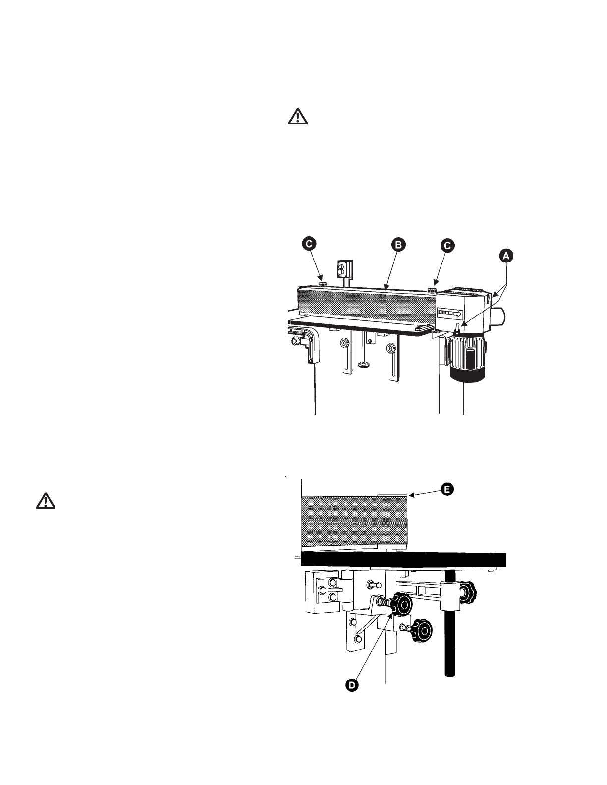
CHANGING SANDING BELT
1. Loosen the two latches (A), on the dust chute,
and open the dust hood, Figure 1.
2. Remove the sanding belt safety guard (B) by
removing the two knobs (C) which are on the guard.
FIGURE 1
3. Rotate the sanding belt tension adjustment knob
(D) clockwise to release idler pulley device (E). See
Figure 2. Remove the old belt.
WARNING: ELECTRICAL WIRING SHOULD
BE DONE BY A QUALIFIED ELECTRICIAN. THE
MACHINE MUST BE PROPERLY GROUNDED TO
HELP AVOID ELECTRIC SHOCK AND ASSOCIATED HAZARDS INCLUDING POSSIBLE DEATH.
If your edge sander is 3-phase, there is a four conductor power source cable. If single-phase, it has a
three conductor power source cable. On both models, the ground conductor is green or yellow & green.
NEVER connect the green wire to a live terminal.
OPERATION
The sander is equipped with a push-button magnetic
control system.
When starting the machine, make sure the rotational
direction is correct. If it is not, the power connection
will have to be changed: If 3-phase, change any two
6
FIGURE 2
Page 7

NOTE: Identify the sanding belt direction before you
install the belt, because the belt's rotational direction
must be the same as the machine. An arrow on the
reverse side of the belt shows the proper direction
and should match the arrow direction on the machine
guard. If the belt has no arrow indicator, find the
joint of the belt (where it is layered) and install it according to Figure 3.
FIGURE 3
4. Place the new sanding belt between the contact wheel and idler pulley, then adjust the tension
adjustment knob (D). Counterclockwise will maximize the tension, clockwise will minimize it.
5. Check that the new belt is tracking correctly by
rotating it with one hand, Figure 4, and use your other
hand to make any adjustments to the track adjustment knob (F). To lower the abrasive belt, rotate the
track adjustment knob clockwise. To raise it, rotate
counterclockwise.
NOTE: The track adjustment mechanism is
very sensitive - make these corrections gently.
6. Replace safety guard (B), close dust hood and
re-tighten knobs (A).
7. Turn machine on and off quickly several times
to check that the sanding belt rotation is normal and
that it tracks properly. If not, repeat the above procedure.
SANDING BELT TENSION SPRING
FATIGUE COMPENSATION
Adjustment of the sanding belt will cause spring fatigue when used for a long period. If this happens,
it's not necessary to change the spring. Simply rotate the tension adjustment screw (A), Figure 5, clockwise until you achieve the proper tension compensation.
FIGURE 5
When properly adjusted, the sanding belt should keep
the same steady level during rotation without moving too high or too low.
FIGURE 4
FRONT WORK TABLE INCLINATION
Using the inclined table method on this edge sander
may give you better sanding surface contact, decreased sanding marks and burr residue, with results equal to that of an oscillating sanding machine.
To adjust the front work table:
1. Loosen the two fixed knobs (A), Figure 6.
2. Raise the front work table (B) by rotating the
adjustment knob (C) and incline it to the degree desired.
3. Re-tighten the fixed knobs (A).
7
Page 8

FIGURE 6
FIGURE 8
STEEL PLATEN ADJUSTMENT
The steel platen is located between the motor contact wheel and the idler pulley. The surface of the
steel platen should protrude about 1/8"-1/4" past the
motor contact wheel and the idler pulley in order to
assure that the sanding belt will be in contact totally
with the steel platen.
Adjust as follows:
1. Remove sanding belt (refer to "Changing Sanding Belt").
2. Loosen the two fixed screws (A), Figure 7, on
the steel platen at the rear of the machine.
MOTOR/SANDING BELT ALIGNMENT
The motor and sanding belt on the edge sander were
factory aligned. However, if they are out of alignment due to shipping, adjust as follows:
1. Adjust front work table to its lowest position.
2. Loosen the two fixed screws on the dust chute
and remove chute from machine.
3. Remove safety guard.
4. Rotate the belt by hand to ensure that it is completely parallel with the steel platen, top left to top
right. Use a straight edge if necessary to measure
this.
5. If the sanding belt left to right is not parallel with
the steel platen, then the motor is not adjusted properly. Loosen the motor mounting screws (A), Figure
9, and adjust with the two jack screws (B).
FIGURE 7
3. Using a straight edge (B), to measure the protruding distance between the surface of the steel
platen and the two pulleys (i.e. motor contact wheel
& idler pulley). See Figure 8.
4. Tap the steel platen with your hand until the protruding distance is 1/8" to 1/4". The platen/motor
contact wheel & platen/idler pulley distances should
be the same.
5. Re-tighten the fixed screws (A) on the platen,
and replace sanding belt.
8
FIGURE 9
6. If the right side of the sanding belt (near the
motor) is too high, adjust motor inclination inward,
until the sanding belt is parallel with the steel platen.
Then tighten the four motor fixed screws (E).
7. Rotate the sanding belt by hand again to make
sure it is completely parallel with steel platen.
8. Replace safety guard and dust hood, and adjust the sanding belt tracking if necessary.
Page 9

MAINTENANCE
LUBRICATION
CAUTION: Disconnect sander from power
source before performing maintenance.
Do not operate the sander until it is properly lubricated.
All ball bearings are sealed for life and do not require
lubrication.
Apply a drop of light machine oil occasionally on the
hinge of the tension mechanisms as shown in Figure 10. Service the machine every 6 weeks.
SANDING BELT SELECTION
Use the chart, Figure 11, for selecting an abrasive
belt. Aluminum oxide is recommended for general
use in the home workshop.
Figure 12 groups abrasives into five classes, indicating the grit numbers that fall into each.
FIGURE 10
EVISARBAESUESRAOC
munimulAdoowdraH04-0308-06021-001
edixOmunimulA0408-06001
reppoC05-04001-08021-001
leetS03-4208-06001
yrovI08-06021-001082-021
citsalP08-05081-021042
TIRG
MUIDEM
FIGURE 11
EPYTENIFYREVENIFMUIDEMESRAOC
edixOmunimulA063-022081-021001-0806-0463-42
FIGURE 12
ENIF
YREV
ESRAOC
9
Page 10

TROUBLE SHOOTING
MELBORPESUACELBISSOPNOITULOS
.tratstonlliwrednaSrekaerbtiucricronwolbesuF.1
.deppirt
.degamaddroC.2
.yltneuqerftuoskcikdaolrevOootrothgilootdrocnoisnetxE.1
.gnol
erusserpdeefroetibevissecxE.2
.taergoot
tcerrocrofderiwtonrotoM.3
.egatlov
otpuemoctonseodtlebgnidnaS
.deeps
.ylevissecxesetarbivenihcaM.roolfnevenunohcnebrodnatS.1
.gnol
.tnerruc)esuoh(woL.2
.egatlov
.taergoot
.yltcerroc
noisnetrofgnirpsehT.4
ootrothgilootdrocnoisnetxE.1
tcerrocrofderiwtonrotoM.3
erusserpdeefroetibevissecxE.4
.gnitnuomrotomreporpmI.2
denoisnettontlebgnidnaS.3
.nekorbrodeugitafsimsinahcem
.esoolootsileehwtcatnoC.5
.rekaerb
.naicirtcele
.droc
.ecroftonod
.gniriwtcerroc
.droc
.gniriwtcerroc
.ecroftonod
.gnitnuom
sitlebfogninoisneT.3
.gnikrowsignirpsehtfo
tiucricteserroesufecalpeR.1
deifilauqybdecalperdrocevaH.2
ezisetauqedahtiwecalpeR.1
-yleerftucottlebgnidnaswollA.2
rofetalpemanrotomotrefeR.3
ezisetauqedahtiwecalpeR.1
.naicirtceledeifilauqatcanoC.2
rofetalpemanrotomotrefeR.3
-yleerftucottlebevisarbawollA.4
.ecafrusleveltalfnonoitisopeR.1
.yrassecenfiroolfotnetsaF
rotomtsujdadnakcehC.2
bonkehthguorhtdehsilpmocca
erusekaM.gnirpsehtslortnoctaht
noisnetllufehtosdesaelersibonk
.gnirpswenhtiwecalpeR.4
rotomniwercspacnethgiT.5
.tfahs
.nekorbtlebgnidnaS.6
.tlebgnidnaswenhtiwecalpeR.6
10
.tlebgnidnasdaB.7
.tlebgnidnaswenhtiwecalpeR.7
.latemnobojetauqedanI.tlebgnidnasgnorW.1nocilisroedixomunimulaesU.1
rotnilfton,stlebgnidnasedibrac
.tenrag
.krownoskramgnidnaSrofesraocoottlebgnidnaS.1
.deriuqerhsinif
.hsiniflanif
.tirgtlebgnidnasgnorW.2
roftlebgnidnasenifyrevesU.1
kcotsroftirgresraocesU.2
.lavomer
.niargssorcadednaskroW.3
esu,gnidnasecafrusnehW.3
hsinifnehttlebgnidnasenifyrev
fonoitceridnignikrow,dnahyb
.niarg
ffoburylkciuqsniarggnidnaS
.tleb
.seitreporplanigiro
stitsolsahtlebgnidnaS.1
stlebgnidnaserotstonoD.1
erehwroyrdylemertxesitierehw
.hgihylemertxeeraserutarepmet
.egarotstcerrocnI.2
.ylreporptlebgnidnaserotS.2
.tidloftonoD
Page 11

TROUBLE SHOOTING (continued)
MELBORPESUACELBISSOPNOITULOS
.sezalgtlebgnidnaS.ecafrusdetniapgnidnaS.1
.ymmugrotewsidooW.2
.snrubkroW.ecafrustlebgnidnasgnorW.1
.lavomer
.taergooterusserpdeeF.2
.netalp
.sselnoitomdlehkroW.3
.krownoskramgnidnaS.sselnoitomdlehkroW.1.gnivomkrowpeeK.1
ylkciuqsgolc,snrubtlebgnidnaS
.gnidnasssenkcihtno
.krownisnoitatnednIenonisselnoitomdlehkroW.1
.tops
.strotsidyellupreldidnegnidnaSdeefroetibevissecxE.1
.erusserp
.dnahmorfdellupkroW.troppusoN.1tnorfehtnopotskrowehtesU.1
ehttanekorbsahtlebgnidnaS
.tnioj
.peedootgnitiB.1noitcagnidnasthgilsroftsujdA.1
.elbat
.noitceridgnorwnigninnurtleB.1htiwnoitceridnoitatorhctaM.1
.gnivomkrowpeeK.3
.gnivomkrowpeeK.1
.ecroftonod,yleerf
.tlebtnilf/niargdne-nepoesU.1
.kcotstnereffidesU.erucoN.2
kcotsroftirgresraocesU.1
leetsotnikrowecrofreveN.2
.sessapdetaeperekamdna
dnasottlebgnidnaswollA.1
.draugenihcamnoworra
.erauqstonegdedednaS.gnidnasdnaheerffotluseR.1
.derisedsi
.dengilasimelbaT.2
.ylgnidroccatsujdA
.levebsahtlebgnidnaS.dengilasimrotoM.1.tnemngilarotomtsujdA.1
elihwdeppordsahtlebgnidnaS
.gnidnas
.ylirotcafsitasnugnidnasrednaSleetsfogninoitisoptcerrocnI.1
.yltcerroc
.nekorbrodeugitaf
.yltcerroc
.netalp
denoisnettontlebgnidnaS.1
.bonkhtiw
signirpsmsinahcemnoisneT.2
gnikcarttontlebgnidnaS.3
.yellup
.gnikcarttsujdA.3
elbatnotalfeceipkrowpeeK.1
egdeerauqsanehwsemitllata
leetsottnemngilaelbatkcehC.2
.seerged09ebdluohstI.netalp
noisnettlebgnidnastsujdA.1
.gnirpswenhtiwecalpeR.2
"4/1ot"8/1netalpleetstsujdA.1
reldidnaleehwtcatnocehtevoba
11
Page 12

PARTS LIST: Model 6108 Edge Sander
NO. PART NO. DESCRIPTION
1 6294030 TABLE, END
4 6294031 PLATE, STEEL END
5 6294032 SCREW, HEX. HD. WOOD,
1/4-20 X 1-1/4
6 6294033 BAR, SUPPORT
7 6294034 SUPPORT, TABLE
8 6294035 KNOB
9 6294036 WASHER, 3/8"
10 6294037 SCREW, HEX HD. 3/8-16 X 1-1/2"
11 6294038 KNOB
12 6294039 NUT, WING
13 6294040 HOLDER, SPRING
14 6294041 SCREW, HEX HD. 3/8-16 X 1-5/8"
15 6294042 NUT, HEX 3/8
16 6294043 SPRING
17 6294044 PLATE, COVER
18 6294045 BOLT, SOC. HD. CAP,
5/16-18 X 2"
19 6294046 HOLDER, IDLER PULLEY
20 6294047 SCREW, SOC. HD. CAP,
1/4-20 X 5/8"
21 6294048 TABLE, FRONT
22 6294049 PLATE, FRONT STEEL
23 6294050 ANGLE, TABLE
24 6294051 SCREW, HEX HD., 3/8-16 X 1"
25 6294052 SCREW, HEX HD., 3/8-16 X 5/8"
26 6294053 HOLDER, HINGE
27 6294054 BLOCK, SPRING ADJUSTING
28 6294055 SPRING
29 6294056 SUPPORT,SWITCH
30 6294057 BOLT, KNOB
31 6294058 RING, RETAINING
32 6294059 BEARING, #6205-LB
33 6294060 GUARD, SAFETY
34 6294061 PULLEY
35 6294062 BELT, ABRASIVE
36 6294063 SUPPORT, GUARD
37 6294064 SHAFT, PULLEY
38 6294065 PLATEN, STEEL
39 6294066 GRAPHITE
40 6294067 RING, RETAINING
41 6294068 SHAFT, HINGE
42 6294069 ANGLE, SUPPORT
43 6294070 BASE
44 6294071 KNOB, TABLE ADJUSTING
45 6294072 SCREW, HEX HD., 1/4-20 X 3/8"
46 6294073 WASHER, 1/4"
47 6294074 SCREW, HEX HD., 5/16-18 X 5/8"
NO. PART NO. DESCRIPTION
48 6294075 WASHER, 5/16"
49 6294076 COVER, BACK
50 6294077 SCREW, WING, 1/4-20 X 5/8"
51 6294078 PIECE, CLAMPING
52 6294079 SCREW, SOC. HD. CAP,
5/16-18 X 1"
53 6294080 WHEEL, CONTACT
54 6294081 SCREW, HEX HD.,
1/2-12 X 2-1/2"
55 6294082 NUT, HEX 1/2"
56 6294083 SCREW, SET, 5/16-18 X 3/8"
57 6294084 MOTOR, 2 HP, 3 PH
6294085 MOTOR, 1-1/2 HP, 1 PH
58 6294086 KEY
59 6294087 HOOD, DUST
60 6294088 ASSEMBLY, PUSH BUTTON
61 6294089 BOX, SWITCH
62 6294090 WASHER
63 6294091 CONTACTOR w/ THERMAL
OVERLOAD RELAY (2 HP)
64 6294092 CONTACTOR w/ THERMAL
OVERLOAD RELAY (1-1/2 HP)
65 6294093 TRANSFORMER 115/230V
6294122 TRANSFORMER 230/460V
66 6294115 STOP, WORK
67 6294116 SCREW, HEX HD 5/16-18 X 2-1/2"
68 6294117 WASHER, 5/16"
69 6294118 NUT, HEX 5/16"
70 6294119 WASHER, 1/2"
71 6294120 LABEL, DIRECTION
72 6294121 WASHER, SPRING, 5/16"
73 6294101 WIRE, MOTOR
74 6294102 CORD, POWER
75 6294103 PROTECTOR, WIRE
76 6294104 SCREW, SOC. HD. CAP,
1/4-24 X 3/8"
77 6294105 WIRE
78 6294106 SCREW, ROUND HD.,
3/16-24 X 5/8"
79 6294107 LABEL, WARNING
80 6294108 CARD, I.D.
81 6294109 LABEL, CAUTION
82 6294110 LABEL, LOGO
83 6294111 STRIPE, COLOR
84 6294112 WASHER, 3/8"
85 6294113 SCREW, HEX HD., 3/8-16 X 3/4"
86 6294114 SCREW, HEX HD., 3/8-16 X 2-1/4"
12
Page 13

EXPLODED VIEW: Model 6108 Edge Sander
13
Page 14

ELECTRICAL SCHEMATIC (6108 Edge Sander)
14
Page 15

ELECTRICAL SCHEMATIC (6108 Edge Sander)
15
Page 16

OPTIONAL ACCESSORIES
6294094 Abrasive Belt, 6" x 108", 40 Grit.
6294095 Abrasive Belt, 6" x 108", 60 Grit.
6294096 Abrasive Belt, 6" x 108", 80 Grit.
6294062 Abrasive Belt, 6" x 108", 100 Grit.
6294098 Abrasive Belt, 6" x 108", 120 Grit.
6294099 Abrasive Belt, 6" x 108", 150 Grit.
6294100 Abrasive Belt, 6" x 108", 200 Grit.
16
Page 17

171819
Page 18

Page 19

To order parts or reach our service department, please call our toll free number between 8:00 A.M. and
4:30 P.M. (CST), Monday through Friday. Having the Model Number and Serial Number of your machine
available when you call will allow us to serve you quickly and accurately. Locating the stock number of the
part(s) required from your parts manual will also expedite your order.
Phone: (800) 274-6848
Fax: (800) 274-6840
If you are calling from Canada, please call 800-238-4746
E-mail: powermatic@wmhtoolgroup.com
Website: www.powermatic.com
Page 20

02/02
WMH Tool Group
P.O. Box 1349
Auburn, WA 98071-1349
Phone: (800) 274-6848
Fax: (800) 274-6840
E-mail: powermatic@wmhtoolgroup.com
Website: www.powermatic.com
C
POWERMATIC ALL RIGHTS RESERVED
 Loading...