

Page 1
8" JOINTER
Model 60A
Instruction Manual & Parts List
M-0460258
(800) 274-6848
www.wmhtoolgroup.com
Page 2

This manual has been prepared for the owner and operators of a Powermatic Model 60A, 8"
Jointer. Its purpose, aside from machine operation, is to promote safety through the use of
accepted correct operating and maintenance procedures. Completely read the safety and maintenance instructions before operating or servicing the machine. To obtain maximum life and
efficiency from your jointer and to aid in using the machine safely, read this manual thoroughly
and follow all instructions carefully.
Warranty & Service
The WMH T ool Group warrants every product it sells. If one of our tools needs service or repair , one of our
Authorized Repair S tations located throughout the United S tates can give you quick service.
In most cases, any one of these WMH Tool Group Repair S tations can authorize warranty repair, assist you in
obtaining parts, or perform routine maintenance and major rep air on your JET , Powermatic, Performax, or
Wilton tools.
For the name of an Authorized Repair S tation in your area, please call 1-800-274-6848.
More Information
Remember, the WMH Tool Group is consistently adding new products to the line. For complete, up-to-date
product information, check with your local WMH T ool Group distributor .
WMH T ool Group W arranty
The WMH Tool Group makes every effort to assure that its products meet high quality and durability standards
and warrants to the original retail consumer/purchaser of our products that each product be free from defects in
materials and workmanship as follow: 1 YEAR LIMITED WARRANTY ON ALL PRODUCTS UNLESS SPECIFIED OTHERWISE. This Warranty does not apply to defects due directly or indirectly to misuse, abuse,
negligence or accidents, normal wear-and-tear, rep air or alterations outside our facilities, or to a lack of maintenance.
THE WMH TOOL GROUP LIMITS ALL IMPLIED W ARRANTIES TO THE PERIOD SPECIFIED ABOVE, FROM
THE DATE THE PRODUCT WAS PURCHASED A T RET AIL. EXCEPT AS ST A TED HEREIN, ANY IMPLIED
WARRANTIES OR MERCHANTIBILITY AND FITNESS ARE EXCLUDED. SOME ST A TES DO NOT
ALLOW LIMITATIONS ON HOW LONG THE IMPLIED WARRANTY LASTS, SO THE ABOVE LIMIT A TION MA Y
NOT APPL Y TO YOU. THE WMH T OOL GROUP SHALL IN NO EVENT BE LIABLE FOR DEA TH, INJURIES
TO PERSONS OR PROPERTY, OR FOR INCIDENT AL, CONTINGENT , SPECIAL, OR CONSEQUENTIAL
DAMAGES ARISING FROM THE USE OF OUR PRODUCTS. SOME ST A TES DO NOT ALLOW THE EXCLUSION OR LIMITA TION OF INCIDENT A L OR CONSEQUENTIAL DAMAGES, SO THE ABOVE LIMIT A TION OR
EXCLUSION MA Y NOT APPL Y T O YOU.
T o take advant age of this warranty , the product or part must be returned for examination, postage prep aid, to an
Authorized Repair S tation designated by our office. Proof of purchase date and an explanation of the complaint
must accompany the merchandise. If our inspection discloses a defect, we will either repair or replace the
product, or refund the purchase price if we cannot readily and quickly provide a repair or replacement, if you are
willing to accept a refund. We will return repaired product or replacement at WMH's expense, but if it is
determined there is no defect, or that the defect resulted from causes not within the scope of WMH's warranty ,
then the user must bear the cost of storing and returning the product. This warranty gives you specific legal
rights; you may also have other rights which vary from state to state.
The WMH Tool Group sells through distributors only . Members of the WMH Tool Group reserve the right to
effect at any time, without prior notice, those alterations to parts, fittings, and accessory equipment which they
may deem necessary for any reason whatsoever.
Page 3

TABLE OF CONTENTS
Safety Rules ......................................................................................................................................4-5
Decal Instruction...................................................................................................................................6
Specifications ....................................................................................................................................... 7
Features ...............................................................................................................................................7
Receiving the Jointer ............................................................................................................................8
Installation & Assembly.........................................................................................................................8
Electrical Installation..................................................................................................................... 9
Mounting Drive Belt ...................................................................................................................... 9
Aligning Pulleys ............................................................................................................................9
Mounting Pulley Guard ................................................................................................................. 9
Mounting Dust Adaptor ................................................................................................................. 9
Adjustments ....................................................................................................................................... 10
Removing Cutterhead Guard...................................................................................................... 10
Leveling T ables...........................................................................................................................10
Adjusting Depth of Cut................................................................................................................ 11
Spring Cutting.............................................................................................................................12
Squaring the Fence .................................................................................................................... 12
Fence Movement & Tilting ........................................................................................................... 12
Installing New Knives .................................................................................................................. 13
Sharpening the Knives................................................................................................................. 14
Cutterhead Removal .................................................................................................................... 15
Bearing Replacement .................................................................................................................. 16
T able Removal............................................................................................................................. 16
Basic Jointer Operation ....................................................................................................................... 17
Surfacing (Planing)...................................................................................................................... 17
Edging (Jointing) ......................................................................................................................... 18
Beveling ...................................................................................................................................... 18
Skewing (Shear cutting) .............................................................................................................. 19
Rabbeting.................................................................................................................................... 19
Push Blocks ............................................................................................................................... 20
Parts Lists & Exploded Views:
Cutterhead Guard Assembly ....................................................................................................... 21
Base & Table Assembly ......................................................................................................... 22-24
Cutterhead Assembly .................................................................................................................. 25
Fence Assembly .................................................................................................................... 26-27
S tand Assembly ..................................................................................................................... 28-29
Knife-Setting Gauge (Optional Accessory)................................................................................... 30
Electrical:
1-1/2 HP, Single Phase, 230 Volt ................................................................................................31
NHD: Single Phase/230 V olt ....................................................................................................... 32
NHD: Three Phase/230/460 V olt.................................................................................................. 33
Magnetic St arters........................................................................................................................ 34
Optional Accessories .......................................................................................................................... 34
Preventive Maintenance Check List ..................................................................................................... 35
Page 4

!
Safety Rules
As with all machines, there is a certain amount of hazard involved with the use of this jointer. Use the machine
with the respect and caution demanded where safety precautions are concerned. When normal safety precautions are overlooked or ignored, personal injury to the operator can result.
Read the manual. Read, understand, and follow the safety instructions found in this manual. Know the limitations and hazards in using the model 60 - 8" Jointer. Decals are placed on each machine as reminders of good
safety practice.
Installation. If mounting machine to the floor, use high quality anchor bolts through the mounting holes on the
base. If using a mobile base, be sure to lock the wheels.
Location. Use extra care in the location of the jointer in the shop. Place the machine so that potential kickback
area is not in line with aisles, doorways, wash stations, or other work areas.
Electrical grounding. Make certain that the machine frame is electrically grounded and that a ground lead is
included in the incoming electrical service. If a cord and plug are used, make certain the grounding lug connects
to a suitable ground. Follow the grounding procedure indicated in the National Electric Code.
Eye safety. Always wear approved safety goggles, glasses, or a face shield when operating this machine.
There are no exceptions to this rule.
Personal protection. Before operating the machine, remove tie, rings, watch and other jewelry and roll up
sleeves above the elbows. Remove all loose clothing and confine long hair. Protective type footwear should be
used. Where the noise exceeds the level of exposure allowed in Section 1910.95 of the OSHA Regulations, use
hearing protective devices. Do not wear gloves.
Guards. Be sure machine guards are in place and in good working order. Use them at all times on operations
where they can be used. If a guard must be removed for any operation, make sure it is replaced immediately
following completion of that operation.
Work area. Keep the floor around the machine clean and free of scrap material, saw dust, oil and other liquids
to minimize the danger of tripping or slipping. Be sure the table is free of all scrap, foreign material and tools
before starting to cut. Make certain the work area is well lighted and that a proper exhaust system is used to
minimize dust. Powermatic recommends the use of anti-skid floor strips on the floor area where the operator
normally stands and that each machine's work area be marked off. Provide adequate work space around the
machine.
Disconnect machine before performing any service or maintenance. A machine under repair should be RED
T AGGED to show it should not be used until the maintenance is complete.
Housekeeping. Before turning on machine, remove all extra equipment such as keys, wrenches, scrap, stock,
and cleaning rags away from the machine.
Power on. On machines equipped with a manual
starter make sure the starter is in "OFF" position
before connecting power to machine.
Never surface stock less than 12 inches long, or
3 inches wide, or 3 inches thick without a hold-down
push block.
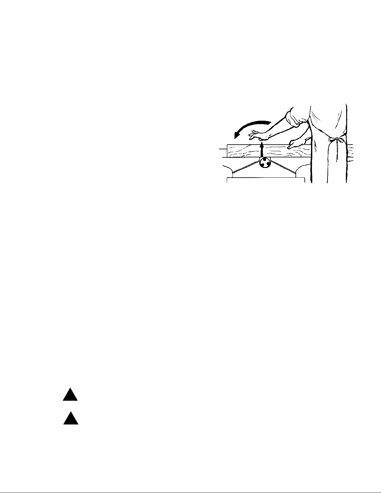
Three inch rule. When working a piece of wood on the
jointer , follow the 3 inch radius rule. The hands must
never be closer than 3 inches to the cutterhead. See
Figure i.
4
FIGURE i
Page 5
Avoid tip-in. Never apply pressure to stock directly over the cutterhead. This may result in the stock tipping into
the cutterhead along with the operator's fingers. Follow the 3 inch rule. Position hands away from extreme ends
of stock, and push through with a smooth, even motion.
Avoid Kickback. "Pull-out" and the danger of kicked back stock can occur when the work piece has knots,
holes, or foreign materials such as nails. It can also occur when the stock is fed against the grain on the jointer .
The grain must run in the same direction you are cutting. Before attempting to joint, or plane, each work piece
must be carefully examined for stock condition and grain orientation.
NOTE: At certain times it may be necessary to plane against the grain when working with a swirl grain wood or
burls. With this type work the operator must use a lesser depth of cut and a slow rate of feed.
Hand safety . It is good practice to move the
hands in an alternate motion from back to front as
the work continues through the cut. Never pass
the hands directly over the cutter knife. As one
hand approaches the knives remove it from the stock
in an arc motion and place it back on the stock in a
position beyond the cutter knife (Figure ii).
NOTE: At all times hold the stock firmly.
Misuse. Do not use this jointer for other than its
intended use. If used for other purposes, Powermatic
disclaims any real or implied warranty and holds itself
harmless for any injury or damage which may result
from that use. Do not equip or use this jointer with a motor larger than 2 Horsepower at 3600 R.P.M. or operate
the cutterhead in excess of 7,000 R.P.M. Use of a larger horsepower motor or higher cutterhead speed voids the
warranty and Powermatic holds itself harmless for any injury which may result.
FIGURE ii
If you are not thoroughly familiar with the operation of jointers, obtain advice from your supervisor , instructor or
other qualified person.
Drugs, alcohol, medication. Do not operate tool while under the influence of drugs, alcohol, or any medication.
Health hazards. Some dust created by power sanding, sawing, grinding, drilling and other construction
activities contains chemicals known to cause cancer, birth defects or other reproductive harm. Some
examples of these chemicals are:
* Lead from lead-based paint.
* Crystalline silica from bricks and cement and other masonry products.
* Arsenic and chromium from chemically-treated lumber.
Your risk from these exposures varies, depending on how often you do this type of work. To reduce your
exposure to these chemicals, work in a well-ventilated area, and work with approved safety equipment, such
as those dust masks that are specifically designed to filter out microscopic particles.
Familiarize yourself with the following safety notices used in this manual:
!
CAUTION: (This means that if precautions are not heeded, it may result in minor or moderate injury
and/or possible machine damage)
WARNING: (This means that if precautions are not heeded, it could result in serious injury or
!
possibly even death).
5
Page 6
!
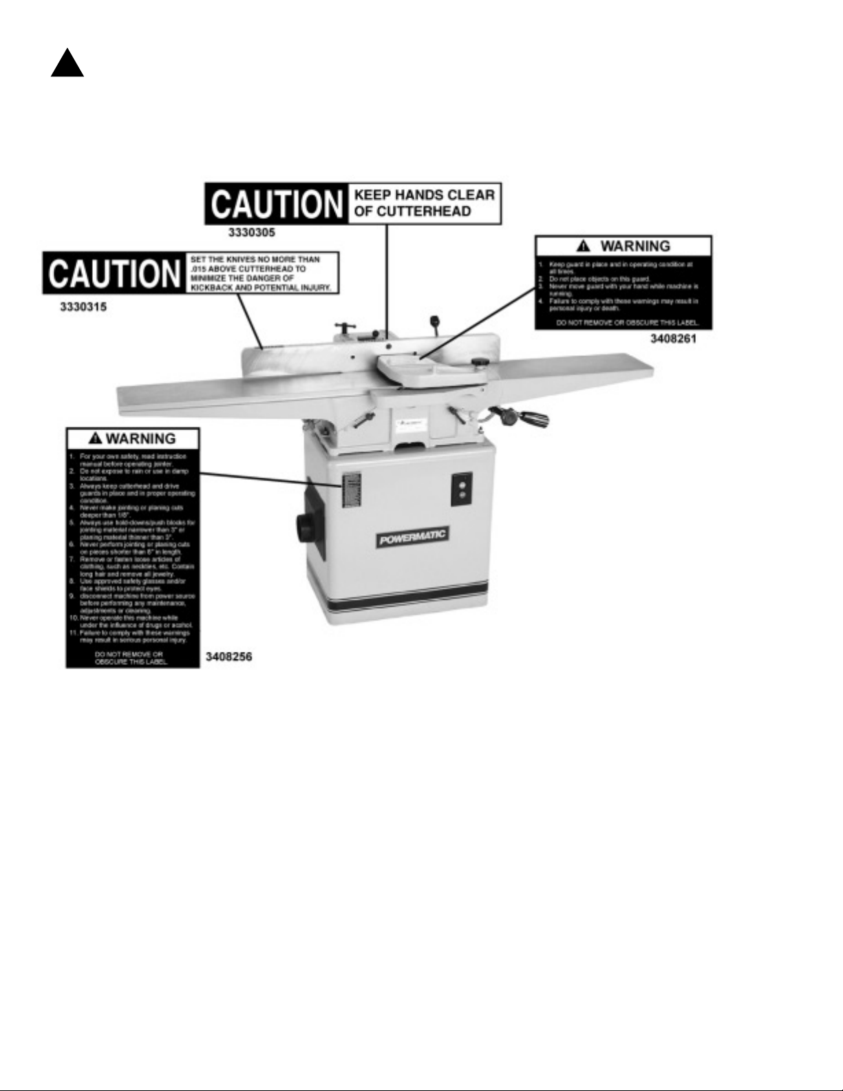
SAFETY DECALS
Familiarize yourself with the location of these decals on your jointer.
6
Page 7
SPECIFICATIONS: Model 60A, 8" Jointer
Table.......................................................................................................................... ...8-1/2" x 72"
Head cutting arc ..........................................................................................................................3"
Knives (3) H.S. steel............................................................................................ 1/8" x 11/16" x 8"
Speed of head (maximum) .............................................................................................7,000 rpm
Knife-cuts-per-minute .......................................................................................................... 21,000
Maximum depth of cut ..............................................................................................................1/2"
Maximum rabbeting cut..................................................................................................... 1/2" x 8"
Fence size overall ...............................................................................................................4" x 36"
Height, less stand ................................................................................................................ 12-1/2"
Height, with stand ................................................................................................................ 35-7/8"
Motor recommended ..................................................................................................... 3/4 to 2 HP
Weight, domestic crated with stand & motor.......................................................................584 lbs.
NOTE: The above specifications were current at the time this manual was published, but due to our policy of
continuous improvement Powermatic reserves the right to change specifications without notice and without
incurring obligations.
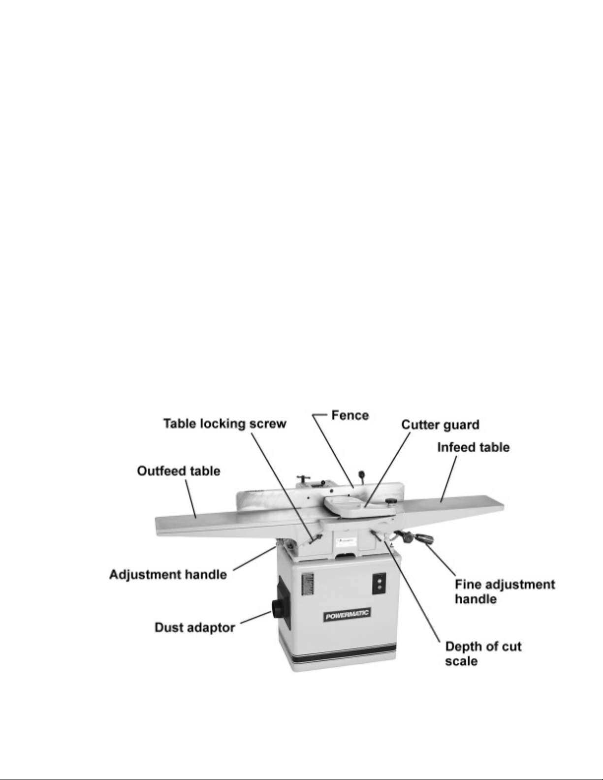
FEATURES of the Model 60A
7
Page 8
RECEIVING THE JOINTER
Remove the jointer assembly and stand from their
respective shipping crates and inspect for damage.
Any damage should be reported to your distributor
and shipping agent immediately . Before proceeding
further, read your manual thoroughly to familiarize
yourself with proper assembly, set-up, maintenance
and safety procedures.
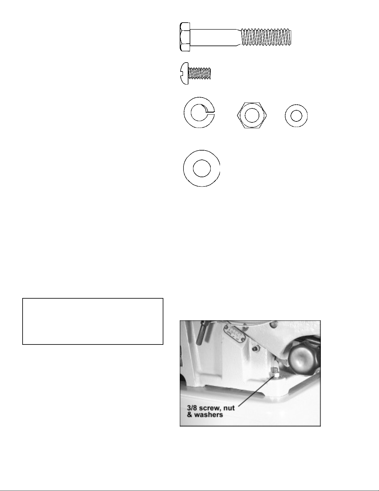
Crate 1 contents:
1 Stand with motor
1 Door
Hex Head Screw
3/8-16x 2-1/4
Qty. 3
Handle Screw
1/4-20 x 1/2
Qty. 4
Crate 2 contents:
1 Table & fence assembly
1 Dust collector adaptor
1 Drive belt
1 Belt guard
1 Cutterhead guard
1 Hardware bag
1 Open-end wrench
The contents of the hardware bag are drawn full scale
in Figure 1.
NOTE: Exposed metal parts such as the table and
fence have been given a protective coating at the factory. This should be removed with a soft cloth and
solvent (such as mineral spirits) once the machine
has been assembled. Do not use an abrasive pad.
INSTALLATION & ASSEMBLY
T ools required
3/8 Lock Washer
Qty. 3
3/8 Flat Washer
Qty. 3
3/8-16 Hex Nut
Qty. 3
FIGURE 1
1/4 Flat Washer
Qty. 4
9/16", 1/2", and 5/8" wrenches
Phillips screwdriver
5/32" hex wrench
Locate jointer on a level floor . If using a mobile base,
be sure to lock the wheels before assembling, operating or adjusting the jointer.
1. With a hoist or an assistant, lift the table and
fence assembly on to the stand, making sure it faces
the right direction (the cutterhead pulley and motor
pulley should line up).
2. Align the holes in the bottom of the jointer bed
with the holes in the top of the stand, and secure with
three 3/8-16 x 2-1/4 mounting screws, three 3/8 hex
nuts, three 3/8 flat washers, and three 3/8 lock washers. Tighten with a 9/16" wrench. See Figure 2.
8
FIGURE 2
Page 9
ELECTRICAL INSTALLATION
WARNING: If the machine does not come
!
wired to run, the electrical and motor
wiring must be done by a qualified
electrician. The machine must be properly
grounded to help avoid electrical shock
and possible death.
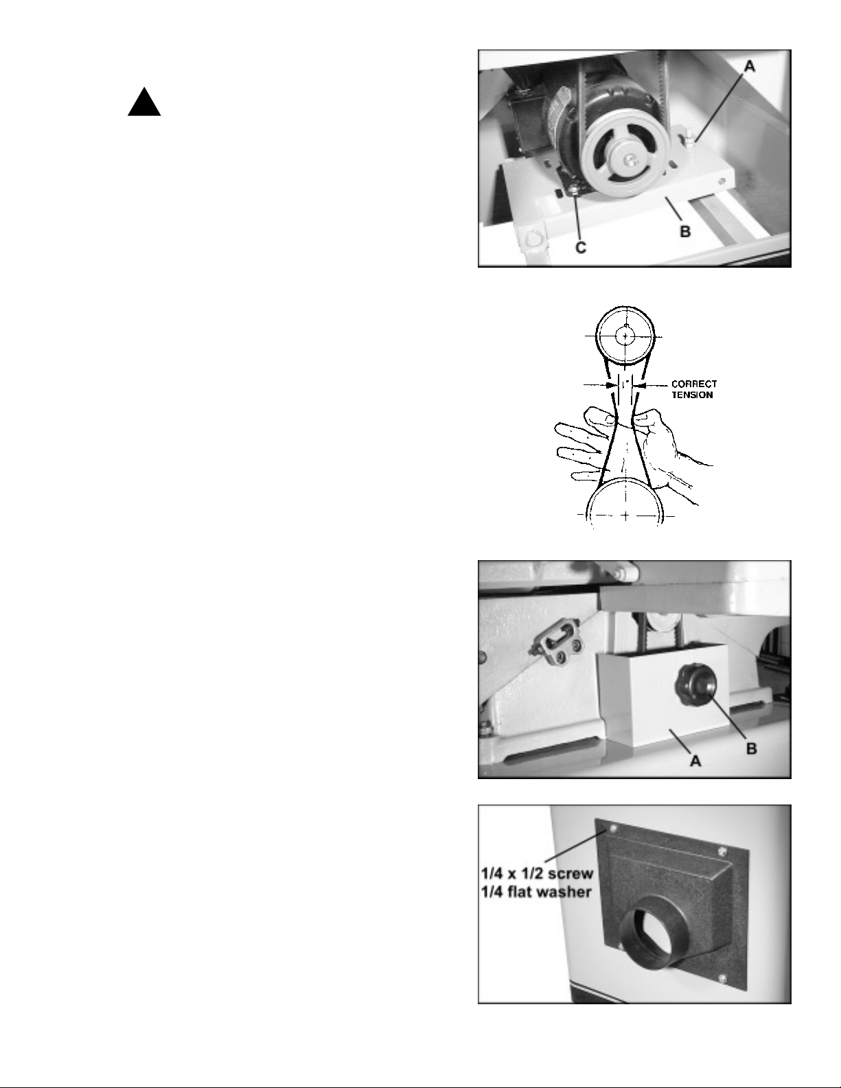
MOUNTING DRIVE BELT
1. Place the belt over the cutterhead pulley and
through the hole in the stand.
2. With a 9/16" wrench, loosen the nut on the adjusting screw (A) of the motor support plate (B) and
lift the motor support up until the belt can be rolled
onto the motor pulley . See Figure 3.
3. Push down on the motor support and retighten
the nut on the adjusting screw (A) to create tension
on the belt.
4. Using thumb and index finger, compress belt at
center until it becomes taut. See Figure 4. At this
point the distance between the in-sides of the belt
should be one inch. Raise or lower the adjusting
screw on the motor support as necessary until this
proper tension is achieved.
ALIGNING PULLEYS
Check that the motor and cutterhead pulleys are
aligned. If adjustments are necessary, loosen the
screws (C) in the motor support plate, as shown in
Figure 3, and slide the motor back or forward as needed.
Re-tighten screws when finished.
FIGURE 3
FIGURE 4
MOUNTING PULLEY GUARD
Place the pulley guard (A) as shown in Figure 5, and
secure by screwing on the knob (B).
MOUNTING DUST ADAPT OR
Place the dust adaptor over the opening in the jointer
stand, and secure with four 1/4-20 x 1/2 handle screws
and four 1/4 flat washers. See Figure 6.
FIGURE 5
FIGURE 6
9
Page 10
ADJUSTMENTS
Check all mounting screws and set screws to see
that they are locked.
CAUTION: Disconnect machine from
!
power source before making adjustments.
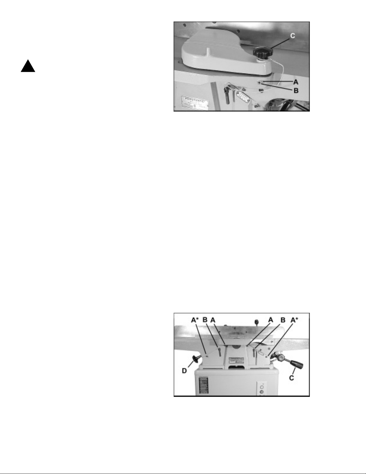
REMOVING CUTTERHEAD GUARD
Some adjustment procedures, as well as rabbeting
operations, will require removal of the guard.
1. Loosen lock nut (A) on rabbeting ledge with a
1/2" wrench. Loosen set screw (B) with a 5/32" hex
wrench. See Figure 7.
2. Vertically lift guard assembly out of the hole.
3. To re-install the guard properly, tension must
be placed on the spring. Push the guard shaft down
into the hole on the rabbeting ledge, and turn the top
knob (C) clockwise until the desired tension is
reached.
4. Continue holding the knob, and tighten the set
screw (B). Tighten the lock nut (A) to prevent set
screw from backing out.
5. With the fence moved back toward the rear
edge of the table, test the guard tension by swinging
the guard away from the fence and then releasing it.
If tension is too strong or too weak, re-adjust as necessary.
NOTE: The guard must operate freely and must not
drag on the rabbeting ledge or infeed table. If dragging occurs, replace the guard assembly .
FIGURE 7
LEVELING TABLES
Periodically check the parallelism of the infeed and
outfeed tables by placing a steel straight edge (or carefully jointed wood) across both tables. Non-parallelism caused by loose gibs may be corrected by the
following procedure:
1. Loosen lock nuts on the gib screws (A), then
loosen the gib screws, and the table lock handle (B).
See Figure 8.
2. Remove lower gib screw (A*) and check screw
hole to make sure that punch mark in the gib is aligned
with the screw hole. If punch mark is not visible, or it
does not line up with screw hole, use a screwdriver to
lightly tap the gib back up into alignment.
3. Replace the lower gib screw (A*) but do not
tighten.
10
FIGURE 8
Page 11
4. Carefully tighten the table lock screw (B) as
shown in Figure 8. The table will begin to move toward the straightedge.
5. When aligned, reset the gib screws (A) until
tight. If table does not align with straightedge, use
the adjusting arm (C) for the infeed table, or
handwheel (D) for the outfeed table, until the table is
flush with the straightedge.
6. Tighten the gib screws (A) then back off approximately 1/4 turn or until the table moves freely,
and reset lock nuts on the gib screws.
If table will not line up:
Remove gib screws and table locking handle and remove gib. Check gib to see that set screws do not go
all the way through the gib or dimple the opposite
side. If either of these conditions exist, replace with
a new gib.
Also, check to be sure the ways are clean and free of
pitch and sawdust. Lubricate gib and way with a good
grade of non-hardening grease.
Replace the gib making certain that the punch mark
lines up with locking screw holes. Replace gib screws.
Repeat steps 3 thru 6.
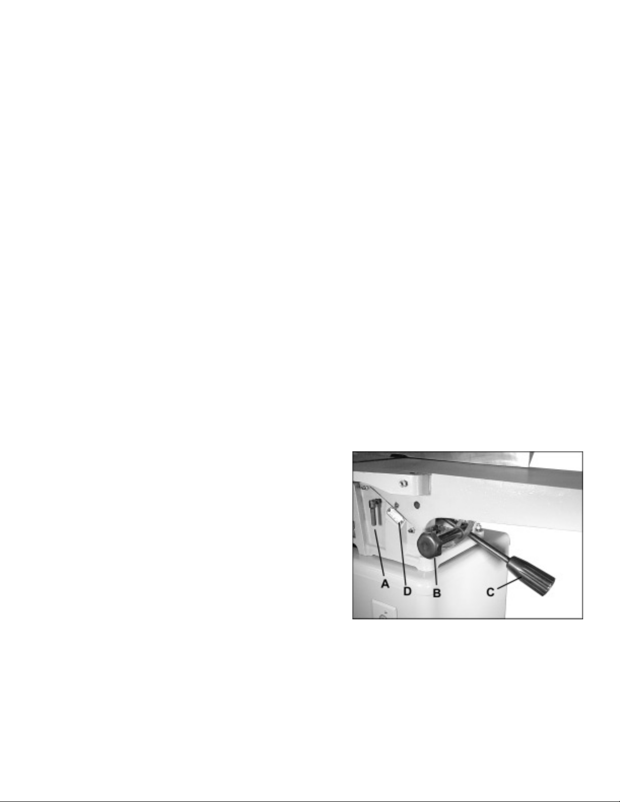
ADJUSTING DEPTH OF CUT
Depth of cut is determined by the height of the infeed
table relative to the cutterhead.
To adjust infeed table:
1. Loosen the lock screw (A), and the locking
handle (B). See Figure 9.
2. Raise or lower the height adjustment handle (C)
until the scale (D) reads approximately at the correct
depth of cut.
3. Turn the locking handle (B) until it is snug, then
fine-tune the adjustment with the height adjustment
handle (C) by rotating it until the scale reads exact.
(Clockwise raises the table, counterclockwise lowers
the table.) The fine adjustment handle has 1/16" travel
per rotation.
4. When set, retighten lock screw (A).
Periodically check the accuracy of the depth of cut
scale (D) by raising the infeed table until it is flush
with the peak of the cutterhead arc (using a straight
edge across table and cutterhead). The scale should
read zero depth. If it does not, readjust the pointer.
FIGURE 9
11
Page 12
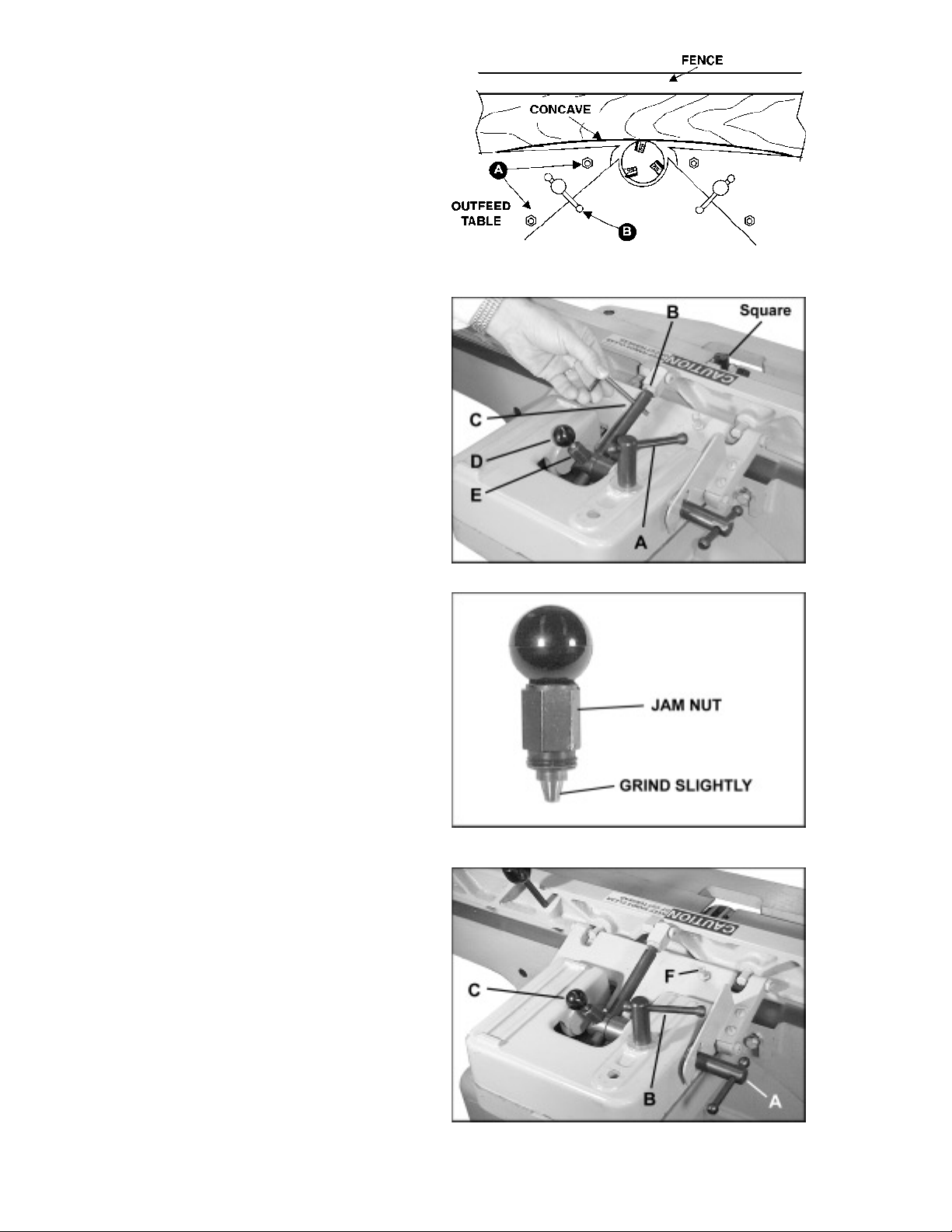
SPRING CUTTING
To spring cut, the outfeed table is lowered below the
level of the cutterhead, as in Figure 10. Loosen both
gib screws (A) on the outfeed table. Amount of enddrop is controlled with the table lock screw (B).
Tighten handle to reduce amount of drop. A 1/32"
drop usually creates the ideal concave for spring joints.
Return the outfeed table to be in line with the
cutterhead knives on completion of the cut.
SQUARING THE FENCE
Before operating the jointer, it is important to check
that the fence is perpendicular to the table.
1. Loosen the lock screw (A), as shown in Figure
1 1, and adjust the fence to the 90 degree position.
(NOTE: There will be some play in the fence when it
is unlocked. All play must be removed by tilting the
fence toward or away from the table while locking the
lock screw. Always remove the backlash by tilting
the fence in the same direction while tightening.)
FIGURE 10
2. Place a 90 degree square on the outfeed table
near the cutterhead, and up against the fence. If the
fence does not come to 90 degrees, make the following correction.
3. Loosen lock nut (B) and insert a tool (such as a
hex head wrench) into the hole in the tilt rod (C).
4. Turn tilt rod clockwise or counterclockwise until
the fence lies flush against the square. Tighten lock
nut (B).
5. Check your adjustment by loosening lock screw
(A) and pulling up plunger (D), allowing fence to tilt
out of 90 degrees. Then return it to 90 degree position.
6. Should the fence fail to return to 90 degrees
and play is evident in the fence, remove the plunger
mechanism (D) by loosening the jam nut (E) with a
5/8" wrench. Inspect the conical portion of the plunger
assembly . If the tilt rod shows signs of wear or scarring, grind the conical portion of plunger, Figure 12,
until it will fully engage in the annular groove in the tilt
rod. Replace plunger assembly and tighten jam nut.
FIGURE 11
FIGURE 12
FENCE MOVEMENT & TILTING
The fence may be moved forward and back across
the table by loosening the lock screw (A) as shown in
Figure 13.
12
FIGURE 13
Page 13

NOTE: Lift up slightly on the fence while moving it to
prevent scratching the jointer table.
The fence may also be tilted forward or backward:
1. To tilt the fence forward in the cradle-cut position, loosen the fence lock screw (B). Pull up on the
fence lock plunger (C) and tilt the fence forward.
2. Check the setting with a machinists protractor
or adjustable square.
3. The two jam nuts (D & E) on the end of the tilt
rod are factory pre-set to stop the forward tilt at 45
degrees. See Figure 14. The front nut (D) is used
for adjusting and the rear nut (E) to lock the setting.
When all adjustments have been made retighten the
fence lock screw (B), Figure 13.
4. T o tilt the fence backward, loosen the fence lock
screw (B). Raise or lower the tilt stop screw (F). When
the desired degree of cut is reached, retighten the
fence lock screw (B).
FIGURE 14
INSTALLING NEW KNIVES
When installing new knives remove only one knife at
a time. Clean the knife slot and install the new knife.
Adjust and lock new knife in cutterhead assembly
before proceeding to next knife.
1. Disconnect jointer from power source.
2. Remove the old knives by loosening gib locking bolts and removing gib, knife, and jack screws,
Figure 15.
3. With a hex head wrench, turn jack screws down
one turn. Clean the jack screws, gib, knife slot, and
knife thoroughly and replace jack screws.
4. Sandwich knife and gib together and drop into
knife slot. Be certain that the back of the knife is
resting on the seat of the jack screw plug.
5. To position the knife for rabbeting cuts, a 1/32
inch shop scale should be placed flat on the end of
the cutterhead or the rabbet slot, whichever extends
the farthest. Slide the knife out until it is flush with the
end of the shop scale. Set the knife locking gib 1/32
inch in from the end of the knife. See Figure 16.
FIGURE 15
FIGURE 16
13
Page 14

Setting the proper knife height:
WARNING: Set the knives no more than
!
.015 inches above the body of the cutter head to minimize the hazard of kickback
and severe personal injury .
6. Snug the two outside gib locking screws.
7. If you have a Quick-Set Knife Gauge (available
from POWERMATIC), place it on the outfeed table
and "0" the indicator as shown in Figure 17.
8. Lift the knife gauge off the outfeed table to see
how far below the bottom of the gauge the indicator
travels. The indicator should read between .025 and
.050 as shown in Figure 18.
9. If the indicator reads outside of this range,
loosen the setscrew in the side of the gauge and adjust the indicator so that it will read within the range
above. Zero the indicator as shown in Figure 17. Repeat this process until indicator reads within the .025
to .050 range. Always zero the indicator (as shown in
Figure 17) before each use.
10. Now place it on the outfeed table to the rear of
the cutterhead with the flat indicator point over the
cutterhead. See Figure 19.
FIGURE 17
FIGURE 18
11. Insert a hex head wrench into the jack screw
and rock the cutterhead back and forth. Watch the
pointer on the knife gauge. The pointer will begin
moving toward "0". When the pointer reaches "0", it
is parallel with the outfeed table.
12. Move the gauge to the front of the cutterhead
and repeat the above procedure.
This adjusting process puts the knife into the knife
slot with the tip parallel and flush with the outfeed
table. Once the correct knife height has been established, secure the gib locking screws. (Begin with
the center screw to prevent buckling or uneven
knives.)
SHARPENING THE KNIVES
After extended use it will be necessary to sharpen
the knives on the cutterhead assembly .
CAUTION: Wear approved eye protection
!
when sharpening knives.
FIGURE 19
1. Disconnect machine from power source and
remove the cutterhead guard (see page 10).
14
Page 15

2. Place a shop scale across the infeed and outfeed
tables, as shown in Figure 20.
3. Set tables to the exact height of the high knife
at the high point of its arc.
4. Clamp a block of wood across the infeed table
so that the end of a sharpening stone may be placed
against the wood block during the jointing operation.
This will help to prevent kickback of the stone. See
Figure 21. Lower the outfeed table .003 inches.
5. Re-connect power and turn machine on.
CAUTION: Keep hands clear of turning
!
cutterhead.
6. Place a hard 10" Arkansas oilstone over
cutterhead with ends resting on infeed and outfeed
tables. Slide the oil stone back and forth across the
tables until knives are jointed lightly. Turn the machine off and visually inspect each knife. If only the
high knife has been touched, lower the outfeed table
and continue the sharpening process until every knife
has been touched by the stone.
FIGURE 20
7. After sharpening knives, place a shop scale on
the outfeed table. Raise the outfeed table to the original setting parallel with the knife at the high point of
the arc.
Weekly sharpening will keep knives in the proper
cutting condition. If knives are excessively worn or
nicked, they must be reground to a new bevel. If this
is the case, follow the above procedure.
CUTTERHEAD REMOV AL
To remove the cutterhead, proceed as follows: (see
Figure 22)
1. Disconnect jointer from power source.
2. Remove fence assembly and drive belt.
3. Remove the nuts and washers from the two
bearing housing retaining screws (A) front and rear .
FIGURE 21
4. Loosen lock knobs (B) and lower infeed and
outfeed tables.
5. Loosen the two hex head screws attaching
fence support (C) with a 9/16" wrench, and turn support 90 degrees on edge as shown.
6. Lift cutterhead straight up from machine.
FIGURE 22
15
Page 16

NOTE: Af ter re-assembly of cutterhead to jointer, the
infeed table will have to be releveled (see "Leveling
Tables", page 10)
BEARING REPLACEMENT
1. Disconnect machine from power source.
2. Remove the the cutterhead assembly (see
"Cutterhead Removal", page 15).
3. Remove bearing housings, Figure 23.
4. Remove bearings with an arbor press or wheel
puller .
5. Use fine emery cloth to remove any fine rust.
Clean the cutterhead shaft and coat with oil.
6. Press new bearing onto shaft, replace bearing
housings, and re-install cutterhead assembly .
FIGURE 23
T ABLE REMOV AL
1. Disconnect machine from power source.
2. Remove the entire fence assembly except for
the support bracket.
3. Remove the cutterhead guard (see page 10).
4. Lower the infeed and outfeed tables and remove
cutterhead (see pg. 15).
5. Loosen the gib set screws and table lock
screws.
CAUTION: After gib screws are loosened,
!
table could suddenly slide down.
6. Remove infeed or outfeed table by sliding upward.
16
Page 17

BASIC JOINTER OPERATION
Before making actual cuts on the stock, make some
practice runs with the power disconnected and the
infeed table raised to "0". This will acquaint the operator with the feel of jointer operations.
This section briefly discusses some of the basic cuts
using a jointer: surfacing, edging, beveling, skewing,
and rabbeting.
SURF ACING (Planing)
The use of push blocks or handle pads will help to
ensure against the operator's hands coming into contact with the cutterhead in the event of a kickback and
as the trailing end of the board passes over the
cutterhead.
Adjust the infeed table for depth of cut. Cuts of approximately 1/16 inch at a time are recommended, as
this allows better control over the material being surfaced. More passes can then be made to reach the
desired depth.
Never surface pieces shorter than 12" or thinner than
3/8" without the use of a special work holding fixture.
Never surface pieces thinner than 3" without the use
of a push block. On stock 8" to 12" long, use a single
two-handed push block, as in Figure 24.
With narrow stock use the type push block shown in
Figure 25.
When surfacing short stock over 4" wide, use two push
blocks to guide material over cutterhead. See Figure
26.
FIGURE 24
FIGURE 25
On stock longer than 12" use two push blocks. Place
a push block near the front of piece and start feeding
wood with the right hand until guard has opened and
cut is started. With the push block, direct pressure
down against the table and back against the fence.
See Figure 27. Place second push block near the
rear of infeed table and continue feeding stock. Before the left hand is in the 3" area of the cutterhead,
move it over to the outfeed side. As soon as possible
follow with the right hand over to the outfeed side and
continue through with the cut.
NOTE: When the stock is longer than twice the length
of the infeed and outfeed tables, an assistant or support table must be used to support the stock.
FIGURE 26
FIGURE 27
17
Page 18

EDGING (Jointing)
Never edge a board that is less than 3" wide, less
than 1/4" thick, or 12" long without using a push block.
CAUTION: When workpiece is twice the
!
length of the jointer infeed or outfeed
table, use an infeed or outfeed support.
Begin by feeding stock with the right hand and applying pressure to front of stock with push block. When
edging, make cuts of approximately 1/16" for hardwood and 1/8" for softwood.
When edging stock wider than 3", lap the fingers over
the top of the wood, extending them back over the
fence such that they will act as a stop for the hands in
the event of a kickback. See Figure 28. Keep stock
against the fence.
BEVELING
When beveling never make a cut deeper than 1/16".
Make certain the material being beveled is over 12"
long, more than 1/4" thick and 1" wide. Set fence to
desired angle.
FIGURE 28
CAUTION: Although the fence may be
!
tilted in or out for a bevel cut, Powermatic
recommends for safety reasons that the
fence be tilted in toward the operator,
making a cradled cut.
For stock wider than 3", hold with the fingers close
together near the top of the stock, lapping over the
board and extending over the fence. See Figure 29.
When beveling material less than 3" wide, use beveled push blocks and apply pressure toward the fence,
as shown in Figure 30. Keep fingers near the top of
the push block.
When beveling short material, use one beveled holddown and apply pressure toward the fence. Keep
thumb above the ledge on the hold-down block. See
Figure 31.
When beveling around four edges of a workpiece, make
cross grain cuts first. This will help clean up any chipping or splintering when beveling the end grain.
When beveling long boards, follow the same procedure used for surfacing long boards (page 17).
FIGURE 29
FIGURE 30
18
FIGURE 31
Page 19

SKEWING (Shear cutting)
When edging or facing burl or birds-eye maple, it is
not unusual to deface or mar the surface being finished. This is caused by the cutterhead blades at
times cutting against the grain. In order to prevent the
defacing or marring of this type wood, it is necessary
to skew , or angle finish, the material being worked.
1. Release the fence locking handle and remove
the two hex nuts and flat washers holding the fence to
the fence support. Remove the fence assembly .
2. Remove the key from the fence slide base.
3. Replace the fence assembly at the desired angle
across the cutterhead. See Figure 32. Secure the
fence to the support with the lock nut, then tighten the
fence locking handle.
RABBETING
WARNING: A rabbet cut requires removal
!
of the cutterhead guard. Use extreme
caution and keep hands clear of the
cutterhead. Always replace guard
immediately after rabbeting operation is
completed.
The width and thickness of the wood to be rabbeted
depends on the width and length of the rabbet. However, never rabbet a piece of wood less than 12" long.
Use push blocks to rabbet cut whenever possible.
1. Disconnect machine from power source.
FIGURE 32
2. Set fence for the desired width of the rabbet.
3. Check the width of the rabbet by measuring the
distance from the end of a knife in the cutterhead to
the fence.
4. Lower infeed table 1/32" at a time and make
successive cuts until the desired depth of rabbet has
been obtained. See Figure 33. NOTE: It is easier
and safer to take a series of shallow cuts.
When rabbeting long pieces, follow the same procedure for surfacing long pieces (page 17).
FIGURE 33
19
Page 20

PUSH BLOCKS
Push blocks are simple, yet necessary tools to assist the operator, especially when jointing thin or short
stock. Two push pads are included with the
Powermatic 60A Jointer .
Figure 34 shows three commonly-used types of push
block that can be easily made from scrap materials.
20
FIGURE 34
Page 21

PARTS LIST: Cutterhead Guard Assembly (60A Jointer)
No. Part No. Description Quantity
1 3250047 Cutterhead Guard ......................................................................................................... 1
2 6760078 Socket Set Screw, #10-32 x 3/8 ................................................................................... 2
3 3406017 Knob ............................................................................................................................. 1
4 6095024 Bronze Bushing, 5/8 x 3/4 OD x 1-1/4 .......................................................................... 1
5 3096220 Guard Spring Collar ...................................................................................................... 1
6 6622005 Cotter Key Pin, 1/8 x 1-1/4 x 1/4................................................................................... 1
7 6114013 Sash Chain, 8 x 2-3/8" Lg ............................................................................................. 1
8 6813022 Extension Spring, J-8-1, 1/2 OD x 3-3/4 Lg .................................................................. 1
9 3711009 Pivot Shaft .................................................................................................................... 1
10 6515007 Hex Jam Nut, 5/16-18................................................................................................... 1
11 6715119 Dog Point Socket Set Screw, 5/16-18 x 1 Lg................................................................ 1
12 6102001 Cable ............................................................................................................................ 1
13 6284104 Cable Fitting ................................................................................................................. 1
21
Page 22

PARTS LIST: Base & Table Assembly (60A Jointer)
No. Part No. Description Quantity
2042373 Jointer Table and Cutterhead Assembly ................................................................... 1
1 6296000 Rear Table .................................................................................................................. 1
2 6285865 Set Screw, 1/4-20 x 3/8 lg ......................................................................................... 6
3 6296001 Collar .......................................................................................................................... 1
4 6296002 Bracket....................................................................................................................... 1
5 6296003 Key, 5mm x 5mm x 12mm ........................................................................................ 1
6 6296004 Lead Screw ................................................................................................................ 1
7 6296005 Bracket....................................................................................................................... 1
8 6285852 Spring Washer, 3/8 x 5/8........................................................................................... 2
9 6296007 Cap Screw, 3/8-16 x 1-1/4 lg ..................................................................................... 2
10 6296162 Spring Washer, 1/2 x 3/4 ........................................................................................... 2
1 1 6296009 Cap Screw, 1/2-13 x 1-1/2 lg ..................................................................................... 2
12 6296010 Bolt ............................................................................................................................. 2
13 6285966 Hex Nut, 5/16-18 ........................................................................................................ 9
14 6296011 Set Screw, 1/4-20 x 1 ................................................................................................ 4
15 6296012 Base ........................................................................................................................... 1
16 6296013 Gib .............................................................................................................................. 2
17 6296159 Cap Screw, 5/16-18 x 1 ............................................................................................. 2
18 6296015 Retaining Ring, ETW-6 .............................................................................................. 3
19 6296132 Bar .............................................................................................................................. 1
20 6296016 Bolt ............................................................................................................................. 1
21 6296017 Shaft ...........................................................................................................................1
22 6296018 Lock Bracket .............................................................................................................. 1
23 6296019 Bracket ....................................................................................................................... 1
24 6296020 Ball ............................................................................................................................. 2
25 6296021 Shaft ...........................................................................................................................1
26 6296022 Retaining Ring, ETW-12 ............................................................................................ 2
27 6296023 Worm .......................................................................................................................... 1
28 6296024 Key, 5mm x 5mm x 20mm ........................................................................................ 1
29 6296025 Adjusting Base ........................................................................................................... 1
30 6296160 Flat Washer, 1/4 x 1-1/2 x 1/32 thk .......................................................................... 4
31 6296027 Hex Screw, 1/4-20 x 3/4 lg ........................................................................................ 1
32 6296029 Worm Shaft ................................................................................................................ 1
33 6296028 Handle ........................................................................................................................ 1
34 6296161 Flat Washer, 1/4 x 3/4 x 1/16 thk ............................................................................. 2
35 6296031 Cap Screw, 1/4-20 x 1/2 lg ........................................................................................ 6
36 6296163 Spring Washer, 1/4 x 1/2 ........................................................................................... 4
37 6296033 Clamp Knob ............................................................................................................... 1
38 6296164 Flat Washer, 1/2 x 1-1/8 x 1/8 thk ............................................................................ 1
39 6296035 Lock Plate .................................................................................................................. 1
40 6296036 Plate ........................................................................................................................... 1
41 6296037 Front Table ................................................................................................................. 1
42 6296038 Handwheel.................................................................................................................. 1
43 6296039 Screw, 5/16-18 x 1/2 lg ............................................................................................. 1
44 6296165 Flat Washer, 3/8 x 3/4 x 1/16 thk ............................................................................. 1
45 6296041 Locking Link ............................................................................................................... 1
46 6296042 Washer, 3/8 ................................................................................................................ 2
47 6296043 Hex Screw, 3/8-16 x 1-1/4 lg..................................................................................... 2
48 6296044 Pointer ........................................................................................................................ 1
49 6296045 Screw, #8-32 x 1/4 lg................................................................................................. 1
50 6296056 Bolt ............................................................................................................................. 1
51 6296057 Belt Guard .................................................................................................................. 1
52 6296058 Knob ........................................................................................................................... 1
53 6296060 Set Screw, 5/16-18 x 3/4 lg....................................................................................... 2
54 6296061 Set Block ................................................................................................................... 1
55 6296062 Bolt ............................................................................................................................. 1
56 6296063 Collar .......................................................................................................................... 1
57 6296166 Flat Washer, 5/16 x 3/4 x 1/8 thk ............................................................................. 6
22
Page 23

PARTS LIST: Base & Table Assembly (60A Jointer)
No. Part No. Description Quantity
58 6285830 Nut, 5/16-18 NC ......................................................................................................... 3
59 6296167 Depth Scale ............................................................................................................... 1
60 VS020500 Rivet, 2mm x 5mm ..................................................................................................... 2
61 6296152 Set Screw, 1/4-20 x 1/4 ............................................................................................. 4
62 6296151 Collar .......................................................................................................................... 2
63 6285917 Push Block ................................................................................................................ 2
64 6296168 Cap Screw, 5/16-18NC x 1/2..................................................................................... 1
65 6296166 Washer, 5/16 x 3/4 x 1/8 thk .................................................................................... 1
23
Page 24

Base & Table Assembly (60A Jointer)
24
Page 25

PARTS LIST: Cutterhead Assembly (60A Jointer)
No. Part No. Description Quantity
1 6296046 Knife ............................................................................................................................. 3
2 6296153 Knife Bar ...................................................................................................................... 3
3 6296048 Key, 5mm x 5mm x 25mm ......................................................................................... 1
4 6296049 Bearing, #6203-2NSE .................................................................................................. 2
5 6296050 Bearing Housing .......................................................................................................... 2
6 6296158 Set Screw, 1/4-20 x 1/2 Lg ......................................................................................... 2
7 6296051 Pulley ........................................................................................................................... 1
8 6285853 Bolt............................................................................................................................... 2
9 6285852 Spring Washer, 3/8 x 5/8............................................................................................. 2
10 6296154 Square Head Screw................................................................................................... 15
11 6296053 Cutterhead ................................................................................................................... 1
12 6296054 Spring ........................................................................................................................... 6
13 6296055 Pan Head Screw, M5-08P x 12mm ............................................................................ 6
14 6296155 Knife Gauge ................................................................................................................. 2
15 6296156 Knife Gauge Rod ......................................................................................................... 1
16 6296157 E-clip, ETW-6 .............................................................................................................. 2
25
Page 26

PARTS LIST: Fence Assembly (60A Jointer)
No. Part No. Description Quantity
2195007 Fence Assembly (Items 1 thru 39) ................................................................................ 1
1 3406201 T eardrop Knob .............................................................................................................. 1
2 3709009 P.F. Control Operator Shaf t........................................................................................... 1
2440005 Plunger Lock Assembly (Items 3 thru 6) ....................................................................... 1
3 3406208 Round Nylon Knob, 1/4-20 x 1 Diameter ...................................................................... 1
4 3601204 Fence Stop Plunger ...................................................................................................... 1
5 3529012 Fence Stop Operating Nut ............................................................................................ 1
6 6813002 Spring, J101 ................................................................................................................. 1
2670015 Rod Assembly (Items 7 thru 9, 14 thru 16, & #2440005 assembly) .............................. 1
7 3670109 Degree Tilt Rod............................................................................................................. 1
8 6567006 Hex Jam Nut, 7/16-20................................................................................................... 1
9 3064038 Table Stop Bracket ....................................................................................................... 1
10 3055120 Mounting Block ............................................................................................................. 1
11 6715064 Shoulder Bolt, 3/8 x 3/4 ................................................................................................ 1
12 6715223 Flat Head Socket Cap Screw , 5/16-18 x 1-3/4.............................................................. 1
13 3773314 Pivot Stud ..................................................................................................................... 2
14 3092046 Fence Tilting Clamp...................................................................................................... 1
15 3728003 Fence Tilting Sleeve ..................................................................................................... 1
16 3526205 Thin Hex Nut, 5/8-18 ................................................................................................... 2
2695038 Fence Lock Screw Assembly (Items 17 thru 19) ....................................................... 1
17 3406016 Knob ............................................................................................................................. 2
18 3695206 Lock Screw .................................................................................................................. 1
19 3268002 Handle .......................................................................................................................... 2
20 3042197 Fence Slide Base ........................................................................................................ 1
21 3195121 Table Fence.................................................................................................................. 1
22 3282009 Fence Mounting Hinge ................................................................................................ 1
23 3695006 Lock Screw .................................................................................................................. 1
24 6715088 Square Head Machine Screw, 5/16-18 x 1 ................................................................. 1
25 6515007 Hex Jam Nut, 5/16-18 ................................................................................................. 1
26 6716117 Slotted Head Set Screw, 3/8-16 x 1-1/2 ..................................................................... 4
27 6516009 Hex Jam Nut, 3/8-16 ................................................................................................... 4
28 6714114 Round Head Machine Screw, 1/4-20 x 3/8 Lg ............................................................ 2
29 6861101 Flat Washer, 1/4 .......................................................................................................... 2
30 3064233 Fence Lock Bracket .................................................................................................... 1
31 6861501 Flat Washer, 1/2 .......................................................................................................... 3
2386003 Fence Sliding Key Assembly (Items 32 thru 33) ....................................................... 1
32 6626056 Spring Pin, 5/32 x 3/4 ................................................................................................. 1
33 3388031 Key, 3/8 x 10-5/16 ....................................................................................................... 1
2526001 Fence Sliding Nut Assembly (Items 34 thru 35) ........................................................ 1
34 3528004 Fence Slide Locknut ................................................................................................... 1
35 6626038 Spring Pin, 1/4 dia. x 1.0 Lg ....................................................................................... 1
36 6716039 Hex Head Screw, 3/8-16 x 1-1/4................................................................................. 1
37 6861300 Spring Lock Washer, 3/8 ............................................................................................. 1
38 6861301 Flat Washer, 3/8 .......................................................................................................... 1
39 3776020 Fence Support ............................................................................................................. 1
26
Page 27

Fence Assembly (60A Jointer)
27
Page 28

PARTS LIST: Stand Assembly (60A Jointer)
No. Part No. Description Quantity
1 6077234 Belt............................................................................................................................... 1
2 6807135 Motor Sheave, 2 HP .................................................................................................... 1
3 6861301 Flat Washer ................................................................................................................. 3
4 6861300 Lock Washer ................................................................................................................ 3
5 6716124 Hex Head Screw, 3/8-16 x 2-1/4 Lg ............................................................................ 3
6 2136013 Door Assembly ............................................................................................................ 1
7 2759030 Jointer Stand Assembly .............................................................................................. 1
8 2004017 Dust Collector Adaptor ................................................................................................ 1
9 6516001 Hex Nut, 3/8-16 ........................................................................................................... 3
10 6471706 Motor, 2 HP, 3 Ph, 208/230/460V ............................................................................... 1
6471707 Motor, 2 H P, 1 Ph, 230V ............................................................................................. 1
11 6756007 Slotted Oval C'Sunk Machine Screw, #6-32 x 3/4 Lg................................................ 2
12 6816292 Starter (Single Phase) ................................................................................................. 1
13 6816295 Starter (Three Phase) .................................................................................................. 1
14 6816296 Starter (Three Phase) .................................................................................................. 1
15 6821496 Pushbutton Switch ...................................................................................................... 1
16 6710015 Socket Head Cap Screw, #10-24 x 1/2Lg .................................................................. 2
17 6510001 Hex Nut, #10-24 ........................................................................................................... 2
18 6860802 Lock Washer, #10 ........................................................................................................ 2
19 6715032 Hex Head Cap Screw, 5/16-18 x 1-1/4Lg................................................................... 4
20 6861200 Lock Washer, 5/16 ....................................................................................................... 4
21 6861201 Flat Washer, 5/16 ........................................................................................................ 4
22 6515001 Hex Nut, 5/16 .............................................................................................................. 4
23 6746023 Hex Washer Head Self Tap Screw, 1/4-20 x 5/8Lg.................................................... 4
24 6050002 Cloth Bag (contains Items 3, 4, 5 & 9) (not shown) .................................................. 1
25 3312341 Powermatic Logo ......................................................................................................... 1
26 3408256 Warning Label .............................................................................................................. 1
27 3119080 American Flag Decal ................................................................................................... 1
28 6471400 Motor, 1-1/2 HP, 1 Ph, 115V ....................................................................................... 1
29 6821365 Pushbutton Switch ...................................................................................................... 1
30 6807134 Motor Sheave, 1-1/2 HP .............................................................................................. 1
31 6710153 Self Tap Screw, #10-24 x 1Lg ...................................................................................... 1
32 6940042 Wire Lug ...................................................................................................................... 2
33 6935003 Connector .................................................................................................................... 2
28
Page 29

Stand Assembly (60A Jointer)
29
Page 30

PARTS LIST: Knife-Setting Gauge 2230035 (Optional Accessory)
No. Part No. Description Quantity
1 3042511 Base............................................................................................................................. 1
2 6391008 Pointer.......................................................................................................................... 1
3 6391006 Indicator ....................................................................................................................... 1
4 6714011 Set Screw .................................................................................................................... 1
30
Page 31

ELECTRICAL (60A Jointer)
Refer to Stand Assembly parts list, page 28.
31
Page 32

ELECTRICAL (60A Jointer)
32
Page 33

ELECTRICAL (60A Jointer)
33
Page 34

ELECTRICAL (60A Jointer)
MAGNETIC STARTERS
Single phase controls
(Stand Assembly 2365016)
ST ARTER
MOTOR CONTACT O R
6471707 2 HP - 230V ......................... 6816292
SWITCH
6821496 Switch (Qty . 1)
Three phase controls
(S tand Assembly 2365014, 2365015)
MOTOR CONT ACTO R
6471706 2 HP - 208/230V ................. 6816295
6471706 2 HP - 460V ........................ 6816296
SWITCH
6821496 Switch (Qty. 1)
OPTIONAL ACCESSORIES
Part No. Description
2042337 Mobile base.
2230035 Knife-setting gauge.
2397077 "Controlled chip" cutterhead retrofit kit
2759091 Jointer stand only .
6285917 Push block.
6427002 (3) heat-treated M-2 high speed tool steel knives, wt. 1 lb.
ST ARTER
34
Page 35

PREVENTIVE MAINTENANCE CHECK LIST
Model 60A Jointer
OPERATOR DATE:
MODEL NO. S/N ASSET NO.
S - Satisfactory A - Acceptable, but needs attention U - Unsatisfactory (red tag)
1. All knives set to be no more than .015 to .025 from cutterhead body. S A U
2. Knives locked securely in cutterhead. S U
3. Knives sharp and free of nicks and grooves. S U
4. Guard in place and working properly . S U
5. Outfeed table in line with top of arc of cutterhead. S A U
All blades arc within .002
6. All safety decals in place. S U
7. Working area around machine marked off. S U
8. Anti-skid strips on floor area where operator normally stands. S U
9. V arious types of push blocks and sticks readily available to operator. S A U
10. Kickback path not aimed at other work areas, aisles, or doorways. S U
1 1. Fence clamps tightly to base and to fence bracket. S A U
12. No missing parts or loose screws. S A U
13. Machine is bolted to floor. S A U
14. Gibs are adjusted to light drag on adjustments for both infeed and outfeed tables. S A U
15. Locks on infeed and outfeed tables are in position and operate properly. S A U
16. Table free of pitch, resin, or any foreign material. S A U
17. Other problems. SAU
FORWARD A COPY OF THIS FILLED OUT FORM TO
YOUR SUPERVISOR FOR IMMEDIATE ACTION
35
Page 36

363738
Page 37

Page 38

Page 39

T o order parts or reach our service dep artment, please call our toll-free number between 8:00 a.m. and 4:30 p.m.
(CST), Monday through Friday . Having the Model Number and Serial Number of your machine available when
you call will allow us to serve you quickly and accurately . Locating the stock number of the part(s) required from
your parts manual will also expedite your order .
Phone No.: (800) 274-6848
Fax No. (800) 274-6840
If you are calling from Canada, please call 800-238-4746
E-mail: powermatic@powermatic.com
Website: www .wmhtoolgroup.com
39
Page 40

05/02
P.O. Box 1349
Auburn, WA 98071-1349
Phone: (800) 274-6848
Fax: (800) 274-6840
E-mail: powermatic@powermatic.com
Website: www.wmhtoolgroup.com
C
POWERMA TIC ALL RIGHTS RESERVED
 Loading...