

Page 1

This .pdf document is bookmarked
Operating Instructions and Parts Manual
Vertical Panel Saw
Model 511
Powermatic
427 New Sanford Road
LaVergne, Tennessee 37086 Part No. M-0460280
Ph.: 800-274-6848 Revision E1 11/2014
www.powermatic.com Copyright © 2014 Powerm atic
shown with optional Adjustable Stop Assembly
Page 2

Warranty and service
Powermatic warrants every product it sells against manufacturers’ defects. If one of our tools needs service or repair,
please contact Technical Service by calling 1-800-274-6846, 8AM to 5PM CST, Monday through Friday.
Warranty Period
The general warranty lasts for the time period specified in the literature included with your product or on the official
Powermatic branded website.
• Powermatic products carry a limited warranty which varies in duration based upon the product. (See chart
below)
• Accessories carry a limited warranty of one year from the date of receipt.
• Consumable items are defined as expendable parts or accessories expected to become inoperable within a
reasonable amount of use and are covered by a 90 day limited warranty against manufacturer’s defects.
Who is Covered
This warranty covers only the initial purchaser of the product from the date of delivery.
What is Co vered
This warranty covers any defects in workmanship or materials subject to the limitations stated below. This warranty
does not cover failures due directly or indirectly to misuse, abuse, negligence or accidents, normal wear-and-tear,
improper repair, alterations or lack of maintenance. Powermatic woodworking machinery is designed to be used with
Woo d. Us e of these machin es in the pro cessi ng of metal, plastics, or oth er materials may v oid the warrant y. The
exceptions are acrylics and other natural items that are made specifically for wood turning.
Warranty Limitations
Woodworking products with a Five Year Warranty that are used for commercial or industrial purposes default to a
Two Year Warranty. Please contact Technical Service at 1-800-274-6846 for further clarification.
How to Get Technical Support
Please contact Technical Service by calling 1-800-274-6846. Please note that you will be asked to provide pro of
of initia l p u rch a s e whe n calling. If a product requires further inspection, the Technical Service representative will
explain and assist with any additional action needed. Powermatic has Authorized Service Centers located throughout
the United States. For the name of an Authorized Service Center in your area call 1-800-274-6846 or use the Service
Center Locator on the Powermatic website.
More Information
Powermatic is constantly adding new products. For complete, up-to-date product information, check with your local
distributor or visit the Powermatic website.
How State Law Appli es
This warranty gives you specific legal rights, subject to applicable state law.
Limitations on This Warranty
POWERMATIC LIMITS ALL IMPLIED WARRANTIES TO THE PERIOD OF THE LIMITED WARRANTY FOR EACH
PRODUCT. EXCEPT AS STATED HEREIN, ANY IMPLIED WARRANTIES OF MERCHANTABILITY AND FITNESS
FOR A PARTICULAR PURPOSE ARE EXCLUDED. SOME STATES DO NOT ALLOW LIMITATIONS ON HOW
LONG AN IMPLIED WARRANTY LASTS, SO THE ABOVE LIMITATION MAY NOT APPLY TO YOU.
POWERMATIC SHALL IN NO EVENT BE LIABLE FOR DEATH, INJURIES TO PERSONS OR PROPERTY, OR
FOR INCIDENTAL, CONTINGENT, SPECIAL, OR CONSEQUENTIAL DAMAGES ARISING FROM THE USE OF
OUR PRODUCTS. SOME STATES DO NOT ALLOW THE EXCLUSION OR LIMITATION OF INCIDENTAL OR
CONSEQUENTIAL DAMAGES, SO THE ABOVE LIMITATION OR EXCLUSION MAY NOT APPLY TO YOU.
Powermatic sells through distributors only. The specifications listed in Powermatic printed materials and on the official
Powermatic website are given as general information and are not binding. Powermatic reserves the right to effect at
any time, without prior notice, those alterations to parts, fittings, and accessory equipment which they may deem
necessary for any reason whatsoever.
Product Listing with Warranty Period
90 Days – Parts; Consumable items
1 Year – Motors, Machine Accessories
2 Year – Woodworking Machinery used for industrial or commercial purposes
5 Year – Woodworking Machinery
NOTE: Powermatic is a division of JPW Industries, Inc. References in this document to Powermatic also apply to
JPW Industries, Inc., or any of its successors in interest to the Powermatic brand.
2
Page 3

Table of cont ents
Warranty and service ............................................................................................................................................ 2
Warning ................................................................................................................................................................. 4
General Operating Instructions ............................................................................................................................. 7
Operating Tips ................................................................................................................................................... 7
511 Panel Saw Features ....................................................................................................................................... 8
Introduction ........................................................................................................................................................... 9
Specifications ........................................................................................................................................................ 9
Installation of Panel Saw ..................................................................................................................................... 10
Uncrating ......................................................................................................................................................... 10
Grounding Instructions .................................................................................................................................... 10
Extension Cords .............................................................................................................................................. 11
Operation ............................................................................................................................................................ 11
Operating Tips ................................................................................................................................................. 11
Crosscutting .................................................................................................................................................... 12
Ripcutting ........................................................................................................................................................ 13
Adjustments ........................................................................................................................................................ 14
Changing the Blade ......................................................................................................................................... 14
Adjusting Crosscut Rulers ............................................................................................................................... 15
Alignment ........................................................................................................................................................ 15
Maintenance ........................................................................................................................................................ 17
Optional Accessories .......................................................................................................................................... 18
Replacement Parts .............................................................................................................................................. 18
511 Panel Saw – Exploded View I .................................................................................................................. 19
511 Panel Saw – Exploded View II ................................................................................................................. 20
Parts List: 511 Panel Saw ............................................................................................................................... 21
511 Panel Saw, Motor with Pushbutton Assembly 2475002 .......................................................................... 23
511 Panel Saw Dust Collection System .......................................................................................................... 24
Electrical Connections ..................................................................................................................................... 25
Parts List: Skilsaw, Model 586, Type 2 (511 Panel Saw) ................................................................................ 26
3
Page 4

Warning
Read and understand the entire owner’s manual before attempting assembly or operation.
Read and understand the warnings posted on the machine and in this manual. Fail ure to comply with all of
these warnings may cause serious injury.
Replace the warning labels if they become obscured or removed.
This panel saw is designed and intended for use by properly trained and experienced personnel only. If you are
not familiar with the proper a nd safe operatio n of a panel saw, do not use until proper tra ining and k nowledge
have been obtained.
Do not use this panel saw for other than its intended use. If used for other purposes, Powermatic disclaims any
real or implied warranty and holds itself harmless from any injury that may result from that use.
Always wear approved safety glasses/face shields while using this panel saw. Everyday eyeglasses only have
impact resistant lenses; they are not safety glasses .
Before operating this panel saw, remove tie, rings, watches and other jewelry, and roll sleeves up past the
elbows. Remove all loose clothing and confine long hair. Non-slip footwear or anti-skid floor strips are
recommended. Do not wear gloves.
Wear ear protectors (plugs or muffs) during extended periods of operation.
Some dust created by power sanding, sawing, grinding, drilling and other construction activities contain
chemicals known to cause cancer, birth defects or other reproductive harm. Some examples of these
chemicals are:
• Lead from lead based paint.
• Crystalline silica from bricks, cemen t and other masonry products.
• Arsenic and chromium from chemically treated lumber.
Your risk of exposure varies, dependi ng on how often you do this type of w ork. To reduce your exposure to
these chemicals, work in a well-ventilated area and work with approved safety equipment, such as face or dust
masks that are specifically designed to filter out microscopic particles.
Do not operate this machine while tired or under the influence of drugs, alcohol or any medication.
Make certain the switch is in the OFF position before connecting the machine to the power supply.
Make certain the machine is properly grounded through the three wire cord that comes with the unit.
Make all machine adjustments, blade changes or m ai ntenance wit h the m achine unpl ugged or locked o ut from
the power source.
Remove adjusting keys and wrenches. Form a habit of checking to see that keys and adjusting wrenches are
removed from the machine before turning it on.
Keep safety guards in place at all times when the machine is in use. If removed for maintenance purposes, use
extreme caution and replace the guards immediately.
Check damaged parts. Before further use of the machine, a guard or ot her part that is damaged should be
carefully checked to determine that it will operate properly and perform its intended function. Check for
alignment of moving parts, binding of moving parts, breakage of parts, mounting and any other conditions that
may affect its operation. A guard or other part that is damaged should be repaired or replaced. Machine should
be properly tagged until repaired.
Provide for adequate space surrounding work area and non-glare, overhead lighting.
Keep the floor around the machine clean and free of scrap material, oil and grease.
Keep visitors a safe distance from the work area. Keep children away.
Make your workshop child proof with padlocks, master switches or by removing starter keys.
Give your work undivided attention. Looking around, carrying on a conversation and “horse-play” are careless
acts that can result in serious injury.
Maintain a balanced stance at all times so that you do not fall or lean against the blade or other moving parts.
Do not overreach or use excessive force to perform any machine operation.
4
Page 5

Use the right tool at the correct speed and feed rate. Do not force a tool o r attachment to do a job f or which it
was not designed. The right tool will do the job better and safer.
Use recommended accessories; improper accessories may be hazardous.
Maintain tools with care. Keep blades sharp and clean for the best and saf est perform ance. Follow instructions
for lubricating and changing accessories.
Turn off the machine before cleaning. Use a brush or com pressed air to remove chips or debris — do not use
your hand s.
Do not stand on the machine. Serious injury could occur if the machine tips over.
Never leave the machine running unattended. Turn the power off and do not leave the machine until it comes to
a complete stop.
Remove loose items and unnecessary work pieces from the area before starting the machine.
Use common sense; keep hands away from and out from under saw carriage at all times.
Do not attempt to disassemble or repair counter-balance.
When the machine is not in use, keep the saw carriage locking knob securely tightened.
Familiarize yourself with the following safety notices used in this manual:
This means that if precautions are not heeded, it may result i n mi nor injury and/or
possible machine damage.
even death.
This means that if precautions are not heeded, it may result i n serious injury or possibly
- - SAVE THESE INSTRUCTIONS - -
5
Page 6
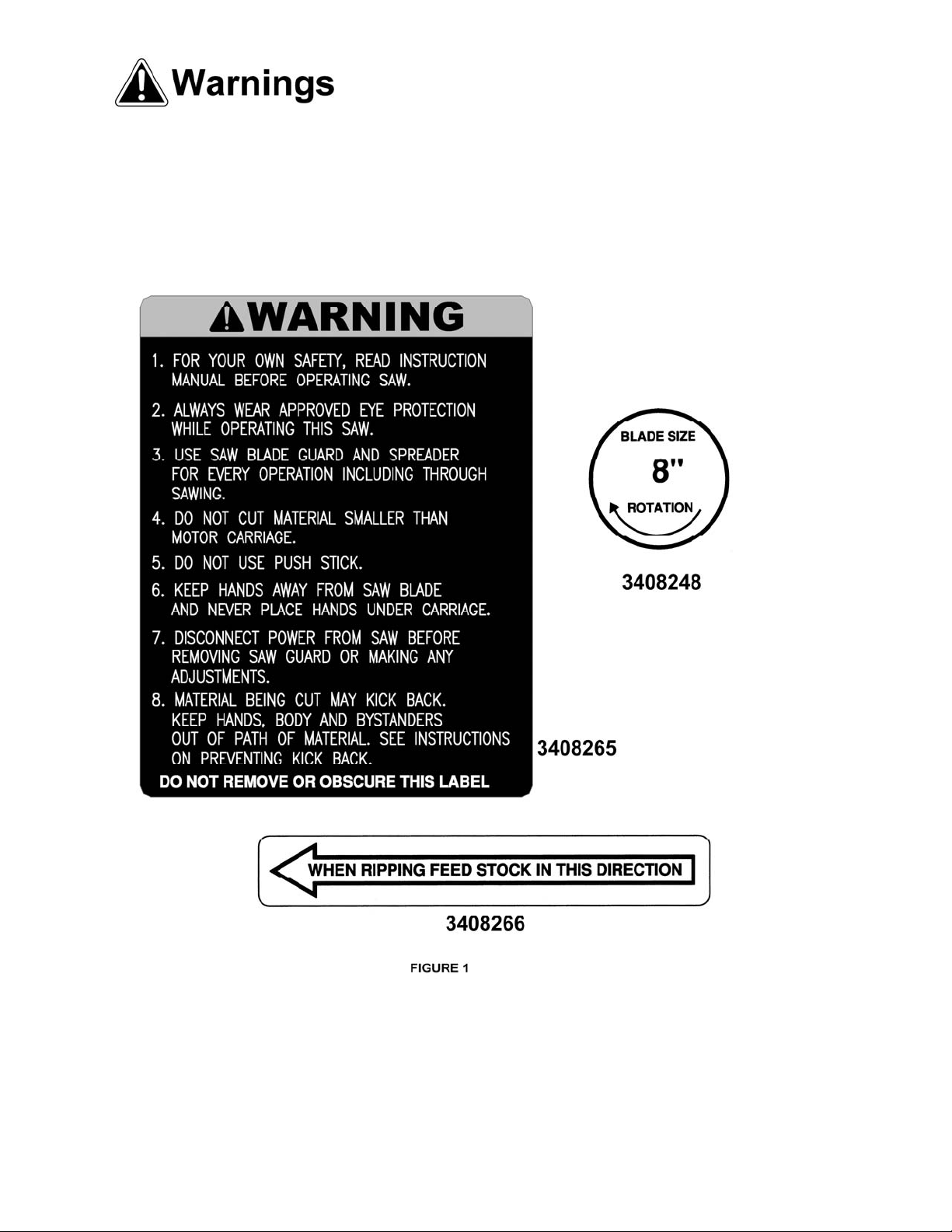
Familiarize yourself with the location and content of these decals on your machine.
6
Page 7

General Operating Instructions
The suggestions listed below are meant to give you a general idea of how your new Panel Saw is intended to
be operated. No amount of instruction can replace good common sense and experience. Be sure the operators
of your new Panel Saw are given enough time and material to become familiar with the general operating
characteristics of this m achine and have FULLY READ AND UNDERSTAND all general operating and safety
instructions. The panel saw is pre-aligned at the factory. No assembly or adjustments are necessary.
NOTE: When your Panel Saw is located in position for operation, secure the machine in a manner that will
prevent it from being tipped over.
Operatin g Tips
1. If you expect smooth, clean, chip-free cuts, follow these tips:
• Use industrial carbide saw blades whic h are SHARP . Dull blades or improperly sharpened blades w ill
cause chipping, unclean cuts, chatter and will overload the saw motor.
• NOTE: ALWAYS USE A SHARP SAW BLADE. IF IN DOUBT REPL ACE IT WITH A NEW BLADE.
• Feeding the material through the machine horizontally or moving the saw carriage through the material
vertically MUST BE DONE SLOWLY, SMOOTHLY AND WHENEVER POSSIBLE WITHOUT
STOPPING. Overfeeding will result in poor quality cuts, shorten the life of the carbide saw blades and
overload the saw motor.
2. Caution must be used when setting material onto the material roller carriage. Heavy materia l MUST NOT
BE DRO PPE D ON TO TH E RO LLER CA RR IAG E. Fa ilure t o fo llow this r u le wi ll u lt im ate ly ca use t he r ol ler
carriage to be pounded out of alignment.
3. For best results place material to be cut onto the Panel Saw with the back side facing the operator. This
will provide the smoothest possible cut on the face side of the panel.
4. Panels being cut horizontally (ripping) mus t always be fed against the rotation of the sa w blade.
5. Do not force the saw. It will perform better and can be more easily controlled if allowed to work at the rate
for which it was designed.
6. If the saw is stopped in mid-cut, allow the blade to stop. Then back up the saw (if crosscutting) or t he
board (if ripping) and restart the saw to continue the cut.
7. Thin material, such as pa neling, should be prope rly supported over its length to prevent bindi ng in the
blade.
8. Panel Saws are designed to cut large panels down to size. As the overall panel size becomes smaller and
smaller other types of sawing machines can become more convenient and safer to use.
7
Page 8
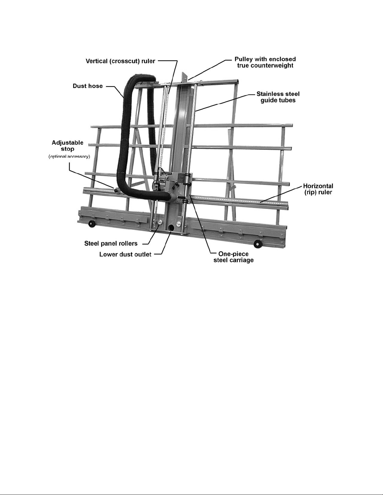
511 Panel Saw Features
Figure 2
8
Page 9

Introduction
This manual is provided by Powermatic, covering the safe operation and maintenance procedures for a Model
511 Vertical Panel Saw. This manual contains instructions on installation, safety precautions, general operating
procedures, maintenance instructions and parts b reakdown. This m achine has been designed and constructed
to provide years of trouble free operation if used in accordance with instructions set forth in this manual. If there
are any questions or comments, please contact either your local supplier or Powerm atic. Powermatic can also
be reached at our web site: www.powermatic.com.
Specifications
Model Number ................................................................................................................................................... 511
Stock Number ........................................................................................................................................... 1510007
Panel Capacity ............................................................................................................................................. 10 feet
Maximum Crosscut Length (in .) .......................................................................................................................... 62
Maximum Rip Length ............................................................................................................................... Unlimited
Maximum Cut Thickness (in.) .......................................................................................................................... 1-1/2
Cut Accuracy, Straight and Square (in.) ........................................................................................................... 1/64
Saw Blade Diameter (in.) ...................................................................................................................................... 8
Power Requirements ...................................................................................................................... 120V, 13 Amps
Footprint (L x W x H)(in.) ................................................................................................................... 120 x 39 x 90
Net Weight (lbs.) ............................................................................................................................................... 435
Shipping Weight (lbs.) ........................................................................................................ ............................... 500
The above specifications were current at the time this manual was published, but because of o ur policy of
continuous improvement, Powermatic reserves the right to change spec ifications at any time and wit hout prior
notice, without incurring obligations.
9
Page 10

Installation of Panel Saw
Uncrating
Remove t he panel sa w from the shipping container
and check for damage. Report any damage to the
freight company immediately.
A wooden block and three cables have been
fastened to the counterweight to secure it during
shipment. This wooden block and cables must be
removed before operation of the saw. Fol low steps
1 through 4:
1. Make sure the cable attached to the motor
carriage is placed over t he pulley o n top of the
panel saw.
2. Loosen the locking knob on the motor carriage
and move the carriage down to the bottom of
the panel saw. See Figure 3. Tighten the
locking knob securely.
3. At the back of the panel saw, on top of the
counterweight housing, lift up on the wood
block and cut the cables attached to the block.
See Figure 4. DO NOT cut the main cable that
runs through the pulley.
4. Remove the cables and wood block so that the
counterweight can slide freely inside the
housing.
Make sure there is enough space o n both side s of
the panel saw for loading, passing, and off-loading
panels.
Grounding Instructions
Improper connection of the
grounding wire can result in electric shock. If
you are unsure whether an outlet is properly
grounded, consult a qualified electrician.
Do not modify the plug provided with the saw and
never remove the grounding prong from the plug. If
cord or plug is damaged, have it repaired before
using the machine. If plug will not fit the outlet,
have a proper outlet installed by a qualified
electrician.
Figure 3
Figure 4
The plug must be connected to a properly
grounded outlet, shown in Figure 5, grounded and
installed in accordance with all codes and
ordinances. If the machine should electrically
malfunction or break down, grounding provides a
path of least-resistance to carry electricity away
from the operator, reducing risk of electric shock.
The grounding prong on the plug is connected
through the green wire inside the cord to the
grounding system in the machine.
The green wire must be the only wire connected to
the machine’s grounding system and must never
be attached to an electrically “live” terminal.
Figure 5
10
Page 11

A temporary adapter, shown in Figure 6, can be
used to connect a grounded plug to a two-prong
outlet. The green rigid ear or lug extending from
the adapter must be connected to a permanent
ground such as a properly grounded outlet box or
receptacle. Simply remove the center screw from
the outlet, insert the adapter and re-attach the
screw through the grounding ear to the outlet. If in
doubt of proper grounding, call a qualified
electrician. A temporary adapter should only be
used until a properly grounded outlet can be
installed by a qualified electrician. The Canadian
Electrical Code prohibits use of temporary
adapters.
Extens ion Cords
Grounded tools require a three-wire extension
cord. As the distance from the supply outlet
increases, a heavier gauge extension cord must be
used. Using extension cords with inadequately
sized wire causes a serious drop in voltage,
resulting in loss of power and possible tool
damage.
Figure 7 shows recommended gauges. The
smaller the gauge number of the wire, the greater
capacity of the cord (for example, a 12-gauge cord
can carry a higher current than a 14-gauge cord). If
one extension cord is used for more than one tool,
add their nameplate amperes and use t he sum to
determine the required minimum wire size.
If you are using an extension cord outdoors, be
sure it is marked with the suffix “W-A” (“W” in
Canada) to indicate that it is acceptable for outdoor
use.
Figure 6
Be sure your extension cord is properly wired a nd
in good condition. Always replace a damaged cord
or have it repaired by a qualified person before
using it. Protect extension cords from sharp
objects, excessive heat, and damp or wet areas.
Operation
Crosscut r ulers: The panel sa w c o m e s w i th o ne rip
(vert ica l) ru ler a nd two cros scut ( horiz onta l) r uler s.
The rip ruler is preset at the factory. The crosscut
rulers should be checked and, if necessary,
adjusted before operating the saw. Also, they
should be adjusted after every blade change. See
“Adjusting Crosscut Rulers” on page 15.
Operatin g Tips
1. Use industrial carbide saw blades that are
sharp. Dull blades may cause chipping, chatter
or overloading of the motor. If you’re not sure
whether a blade is sharp, replace it wit h a new
one.
Figure 7
11
Page 12

2. Feed material through the saw (ripping) or
lower the carriage (crosscutting) slowly,
smoothly and whenever possible without
stopping. Overfeeding can result in poor
quality cuts, shorten the life of the blade, and
overload the motor.
3. Do not drop heavy material onto the rol lers, as
this will eventually pound them out of
alignment.
4. For best results, place workpiece onto saw
with its backside facing the operator. This
provides the smoothest cut on the face side of
the panel.
5. Feed workpiece against the rotation of the saw
blade when making horizontal cuts (ripping).
6. Panel saws are for cutting large panels down
to size. As the panel gets smaller, other types
of tools become safer and more convenient to
use.
Crosscutting
A crosscut is a vertical cut that is made from the
top to the bottom of the workpiece. See Figure 8.
Figure 8
Do not place hands on or
under the carriage or in path of saw blade.
For safety and accuracy, the workpiece must be
supported on at least two rollers while crosscutting.
See Figure 8.
When the optional Short Panel Fence is used, the
workpiece must extend at least 4" beyond both
sides of the carriage, Figure 9.
Here is the basic procedure for crosscutting:
1. Position the saw motor in the crosscutting
position with the blade oriented vertically.
2. Loosen carriage locking knob and move
carriage to the top of the guides.
3. Move the adjustable stop (optional accessory
no. 511-ASA), shown in Figure 10, to the
measurement on the horizontal scale (either
left or right side of carriage) that matches the
desired width of your cut.
4. Place the workpiece on top the rollers. DO
NOT DROP it on the rollers.
5. Slide workpiece into position against the
adjustable stop, while double checking the cut
size via the crosscut rulers. Make sure
workpiece is adequately supported. Use one
hand to guide it.
Figure 9
Do not hold workpiece so that
your hand is behind the carriage or guides or
near the path of the blade.
Figure 10
12
Page 13

6. Start motor and allow it to reach full speed.
7. Pull carriage down slowly and smoothly as the
blade moves through the workpiece. Keep
one hand on the handle at all times and do not
force the saw.
NOTE: If the blade binds in the workpiece, or
the workpiece shifts during the cut, stop the
motor, return the carriage to the top of the
guides, restart motor, and t hen begin the cut
again.
8. Support and remove the cut-off piece as the
saw completes its cut.
9. Once the cut is complete, turn off the motor
and wait for the blade to come to a full stop
(NOTE: A coasting saw blade can mar the
edge of a freshly cut workpiece).
10. Remove the workpieces, return the carriage to
the top of the guides, and lock the carriage.
Ripcutting
A ripcut is a horizontal cut made right to left. See
Figure 11. The workpiece m ust always be moved
in the direction of the arrow on the carriage.
Ripping must be done in
direction of the arrow on saw carriage to
prevent risk of injury.
The minimum length recommended for rip
(horizontal) cuts is 2-1/2 feet, so that the workpiece
can be supported by at least four rollers. (This
measurement also applies when using the optio nal
Short Panel Fence). Pieces shorter than 4 feet can
be rotated 90 degrees and be crosscut.
Here is the basic procedure for ripcutting:
1. Make sure there is enough space on both
sides of saw to completely load, pass, and
offload the workpiece.
2. Pull indexing pin on turntable (Figure 12), and
rotate turntable counterclockwise. The
indexing pin will lock into place.
3. Select height of saw blade above t he rollers.
Move the carriage until the index tab is aligned
with the corresponding dimension on the
vertical ruler. Lock the carriage securely to the
guides with the locking knob.
4. Start motor and allow it to reach full speed.
5. Place workpiece on the side of machine
according to direction of cut shown by the
arrow on the carriage. DO NOT DROP
workpiece on rollers.
6. With the motor at full speed, move the
workpiece slowly and smoothly through the
saw. Do not force the workpiece, as it may
cause binding.
Figure 11
Figure 12
13
Page 14

NOTE: If the blade binds in the workpiece, or
the workpiece shifts during the cut, stop the
motor, back the workpiece out of the saw,
reposition workpiece, restart motor, and then
begin the cut again.
Do not place hands, clothing
or body parts under carr iage or in cutting path
of blade. Do not look directly down line of cut
as dust and debris are generated during this
operation.
7. As the workpiece passes through the saw,
move to the other side and complete the cut
by pulling the workpiece past the blade.
Support the upper piece to prevent it from
pinching the blade or the kerf protector, or
falling away from the machine.
8. When cut is finished, turn off motor and wait
for blade to come to a complete stop. Remove
workpieces.
9. Rotate turntable back to vertical position and
return it to the top of the guides. Lock the
carriage.
Adjustments
The 511 Panel Saw is preset at t he factory, so no
adjustments should be necessary at first.
However, certain alignments should be checked,
and as the saw gets more use adjustments may be
needed.
Changing the Blade
1. Disconnect saw from power source and
observe appropriate lockout procedures to
prevent machine from being accidentally
powered.
2. Tighten carriage lock and remove the blade
guard by unscrewing and removing t he knob,
shown in Figure 13.
3. Engage spindle lock (Figure 14) o n the motor
to keep spindle from turning. Use the wrench
provided to loosen and remove the arbor bolt
(NOTE: left hand threads, turn clockwise to
loosen). See Figure 1 5.
4. Rem ove outer flange, blade, and inner flange.
See Figure 15.
5. Clean spindle, flanges, bolts and blade to
remove dust and debris.
6. Re-install inner flange, and install new blade
with arrow pointing as shown in Figure 15.
Reinstall outer flange and tighten arbor bolt
with wrench.
7. Re-install blade guard.
8. Loosen carriage lock and move carriage to the
top of the guides. Reconnect power.
Figure 13
Figure 14
Figure 15
14
Page 15

Adjusting Crosscut Rulers
The panel saw comes with one rip (vertical) ruler
and two crosscut (horizontal) rulers. The rip ruler is
preset at the factory. The crosscut rulers should be
checked and, if necessary, adjusted before
operating the saw. Also, they may have to be
adjusted after every blade change. With the blade
installed, do the following:
1. Remove blade guard.
2. Loosen carriage locking knob and lower
carriage down to the rulers.
3. Using a square that measures at least 14" on
one side, line up one edge of the square with
the tips of the saw blade, and the other edge
with the crosscut ruler. See Figure 16.
4. If these are out of square, loosen the three
bolts that hold the angle bracket to which the
scale is attached. Slide the angle bracket so
that its measure matches the measure on the
square.
5. Repeat the above steps for the crosscut ruler
on the other side.
6. Make a test cut to verify that the ruler is lined
up correctly .
Figure 16
Alignment
If the saw ever needs realignment, it should be
performed in the following order:
1. Align rollers.
2. Align guides perpendicular to rollers.
3. Align blade parallel to guides.
To ensure accuracy over t he full movement of t he
saw, construct a test square as follows, (Figure
17):
Use a 6-foot metal ruler and two 4-foot metal rulers
(using the 3-, 4-, and 5-ft. measurements ensures
squareness). Drill holes and attach the rulers with
pop rivets or small nuts and bolts.
The 6-foot ruler is used to check squareness of the
rollers. The 4-foot ruler is used to check
squareness of the guide tubes.
Figure 17
15
Page 16

Step 1: Align Rollers
The two outermost rollers are fixed, so adjust all
other rollers to them. Place the 6-foot edge of the
square across the rollers to check for alignment.
The edge of the square should touch all rollers. If it
does not, adjust as follows:
1. Clamp the straightedge to the top of the
outermost rollers and flat to the frame.
Position the clamps above the outermost
rollers.
2. Turn each roller to ensure it does not jam or
have excessive clearance from the
straightedge. If this occurs, loosen the roller
nut, shown in Figure 18.
3. The adjustable rollers have an eccentric hub.
Turning the roller when the roller nut is loose
changes the position of the roller. Turn the
roller until it touches the straightedge, making
sure the straightedge does not bend. NOTE:
The roller panel may have to be loosened in
order to turn the roller. See Figure 18.
4. When the roller is positioned, tighten t he roller
nut. NOTE: If a fixed roller has been replaced,
the above procedure should be repeated.
5. Leave the test square clamped to the rollers
for the next step.
Step 2: Align Guides
Figure 18
Disconnect saw from power
source before aligning the guides.
If the saw does not cut at 90 degrees, t he guides
may not be perpendicular to the rollers. Adjust as
follows:
1. Make sure the rollers are aligned.
2. Remove the blade guard and mark a blade
tooth as a reference (NOTE: If the saw has a
high speed steel blade, mark a tooth that
points toward the edge of your test square,
which is still clamped above the rollers.)
3. Pull the carriage down until the reference tooth
of the blade just touches the vertical edge of
the test square, Figure 19. Continue pulling
the carriage down; if the blade does not
contact the square, or the blade binds on the
square, the guides are not aligned properly.
4. Loosen the guide bracket nuts, Figure 20, but
do not remove the bracket. With a dead blow
mallet, strike the bracket on the side in the
direction you want the guides to go. Do not
strike the guides.
5. Confirm the squareness of guides to rollers as
described above. When satisfied, re-tighten
guide bracket nuts.
Figure 19
Figure 20
16
Page 17

STEP 3: Align Blade Parallel to Gu ides
The blade must move parallel to the guides or tail
burning may occur, and the kerf may be wider than
the set of the blade. Always adjust the rollers and
guides before adjusting the blade. To check for
blade alignment:
1. Make sure rollers and guides are aligned first.
2. If the blade “heels”, or leaves burn marks on
the cut, move the carriage to a crosscut
position and make a test cut. Examine both
sides of the cut to determine which side of the
blade is causing the problem.
3. Disconnect power from the saw.
4. Place your test square on the rollers and lower
the carriage so the test square overhangs the
blade.
5. Place the test square against the blade. The
entire face of the blade should contact the test
square; if it does not, the blade is in need of
alignment.
6. Loosen, but do not remove, the two nuts
holding the indexing pin assembly. See Figure
21.
7. If burn marks appear on the left side of the
workpiece, rotate saw clockwise until entire
face of blade contacts your straightedge. If
burn marks appear on the right side of
workpiece, rotate saw counterclockwise until
entire face of blade contacts your
straightedge.
8. Retighten nuts holding indexing pin assembly.
9. Make a test cut and further adjustments if
necessary.
Maintenance
Figure 21
Always unplug panel saw
before performing any adjustments or
maintenance. Do not disassemble or do any
rewiring to the electrical system; contact a
qualified electrician. Always follow proper
lockout/tagout procedures during servicing.
Keep the machine in good working order by
adopting a routine maintenance program.
Daily:
Use a mild soap and a damp cloth to clean the
machine. Before using the saw each time, clean
dust from the motor housing vents. Keep the
handles clean, dry and free from oil or grease.
Examine the condition of guards, switches, and
power cords. Check for misalignment, binding of
moving parts, broken parts, loose screws and
bolts, etc. If vibration or unusual noise occurs, turn
off the saw and correct the problem immediately.
17
Page 18

Do not use cleaning solvents
such as gasoline, turpentine, lacquer thinner,
paint thinner, or ammonia, as these are harmful
to plastic and some of the insulated parts on
the machine. Never use flammable or
combustible solvents around tools.
Do not immerse the saw in
liquid as this may create risk of injury, electric
shock and damage to the saw.
Periodically:
1. The carriage is designed to move smoothly
along the guide tubes. If the guide tubes
become caked with dust, the carriage may not
slide evenly or become stuck. Occasionally
clean the guide tubes with a damp cloth and
apply a dry lubricant such as a spray silicone.
2. Rotate the motor to horizontal position and
check the motor oil level at the plug. Figure 22
shows the location of the oil plug. If low, fill
with SAE 70 or 80 gear oil to proper leve l. The
gear oil should be changed at least once a
year, or more frequently if the panel saw
receives heavy use.
Every six months:
1. Examine the motor brushes, and replace as
necessary.
2. Inspect and clean gears, spindles, bearings,
housing, etc.
3. Inspect switch, cord, armature, etc.
4. Test to ensure proper mechanical and
electrical performance.
Figure 22
Optional Accessories
511-ASA ....... Adjustable Stop Assembly
Replacement Parts
Replacement parts are listed on the followi ng pages. To order parts or reach our service departm ent, call 1800-274-6848, Monday through Friday (see our website for business hours, www.powermatic.com). Having the
Model Number and Serial Number of your machine available when you call will allow us to serve you quickly
and accurately.
18
Page 19

511 Panel Saw – Exploded View I
refer to parts list, pages 22-24
19
Page 20

511 Panel Saw – Exploded View II
20
Page 21

Parts List: 511 Panel Saw
Index No. Part No . Description Size Qty
.................. 2078021 .................... Carriage Assembly (I tems 15, 17 & 24) ................... ...................................... 1
1 ............... 2218033 .................... Frame Assembly ...................................................... ...................................... 1
2 ............... 2423020 .................... Leg Assembly .......................................................... ...... ................................ 1
3 ............... 3064715 .................... Leg Fold Out Bracket ............................................... ...................................... 2
.................. 511-ASA .................... Adjustable Stop Assembly [Optional Access.] (Index # 4,5,43) ...................... 1
4 ............... 3761160 ................... Adjustable Stop........................................................ ...................................... 1
5 ............... 3064716 ................... Stop Clamp Bracket ................................................. ...................................... 1
6 ............... 3019093 .................... Scale Mounting Angle .............................................. ...................................... 2
7 ................ 3673091 .................... Panel Roller ............................................................. .................................... 10
8 ................ 3745052 .................... Roller Bushing ......................................................... ...................................... 2
9 ................ 3578352 .................... Roller Panel ............................................................. ...................................... 2
10 .............. 3575079 ................... Foam Pad ................................................................ ...................................... 2
11 .............. 2253075 ................... Guide Tube Assembly ............................................. ...................................... 1
12 .............. 3449005 .................... Motor Carriage Lock Assembly (index # 41, 71, 98, 99)................................. 1
13 ............. 3596129 ................... Scale Mounting Plate ............................................... ...................................... 1
14 .............. 3601213 .................. Indexing Plunger ...................................................... ...................................... 1
15 .............. 3079220 .................. Motor Carriage ......................................................... ...................................... 1
16 .............. 3575078 .................. Bearing Wear Pad ................................................... ...................................... 1
17 .............. 3745049 ................ Rotating Disc Spacer ............................................... ...................................... 1
18 ............. 3042513 ................ Motor Mounting Base............................................... ...................................... 1
19 .............. 3064746 ................... Lower Mounting Bracket .......................................... ...................................... 1
20 ............. 2250234 .................... Guard Assembly ...................................................... ...................................... 1
21 ............. 3064745 .................... Upper Mounting Bracket .......................................... ...................................... 1
22 .............. 3046221 .................... Guide Roller ............................................................. .................................. 216
23 .............. 2750008 .................... Splitter Assembly ..................................................... ...................................... 1
24 .............. 3127019 .................... Rotating Disc ........................................................... ...................................... 2
25 .............. 3064720 .................... Indexing Pin Bracket ................................................ ...................................... 1
26 .............. 3268220 ................... Pull Handl e .............................................................. ...................................... 1
27 .............. 3064750 ................... Handle Bracket ........................................................ ....... ............................... 1
28 .............. 3326003 .................... Scale Indicator ......................................................... ...................................... 1
29 .............. 3088029 .................... Counterbalance Channel ......................................... ...................................... 1
31 .............. 3848016 .................... Counter Weight ........................................................ ...................................... 1
32 .............. 3070250 .................... Pulley Bushing ......................................................... ...................................... 1
33 .............. 3064741 .................... Pulley Mounting Bracket (LH) .................................. ...................................... 1
34 .............. 3064742 .................... Pulley Mounting Bracket (RH) ................................. ...................................... 1
35 .............. 6715289 .................... U-Bolt ....................................................................... ...................................... 8
36 .............. 6861301 .................... Flat Washer ............................................................. 3/8 ............................... 24
37 .............. 6516002 .................... Nylon Loc Nut .......................................................... 3/8-16 .......................... 30
38 .............. 6716216 .................... Screw ....................................................................... 3/8-16 X 3-1/2 ............... 2
39 .............. 6716217 .................... Screw ....................................................................... 3/8-16 X 2-1/2 ............. 12
40 .............. 6516028 .................... Wing Nut .................................................................. 3/8-16 ............................ 2
41 .............. 6715020 .................... Socket Head Cap Screw.......................................... 5/16-18 X 1 ................... 6
42 .............. 6861200 .................... Lock Washer ............................................................ 5/16 ............................. 15
43 .............. 6430051 .................... Locking Knob ........................................................... ...................................... 1
44 .............. 6715017 .................... Socket Set Screw .................................................... 5/16-18 x 1 .................... 1
45 .............. 6108003 .................... Caster ...................................................................... 4" ................................... 2
46 .............. 6714270 .................... Eyebolt ..................................................................... 1/4-20 w/ Nut................. 2
47 .............. 6514022 .................... Nylon Loc Nut .......................................................... 1/4-20 ............................ 2
48 .............. 6514011 .................... Jam Nut ................................................................... 1/4-20 ............................ 1
49 .............. 6714269 .................... Hex Head Screw ...................................................... 1/4-20 X 3/4 .................. 4
50 .............. 6714015 .................... Screw ....................................................................... 1/4-20 X 1/2 .................. 2
51 .............. 80-3133 ..................... Knob ........................................................................ ...................................... 1
52 .............. 6515001 .................... Hex Nut .................................................................... 5/16-18 ........................ 16
53 .............. 6861201 .................... Flat Washer ............................................................. 5/16 ............................. 18
54 .............. 6716030 .................... Screw ....................................................................... 3/8-16 X 3/4 ................ 14
55 .............. 6430052 .................... Knob ........................................................................ ...................................... 1
56 .............. 6813142 .................... Spring ...................................................................... ...................................... 1
57 .............. 6430050 .................... Locking Knob ........................................................... ...................................... 1
21
Page 22

Index No. Part No . Description Size Qty
58 .............. 6716218 .................... Hex Head Screw ...................................................... 3/8-16 X 5 ..................... 1
59 .............. 2063181 .................... Motor Bracket Strain Relief Assembly ..................... ...................................... 1
60 .............. 6823020 .................... Indicator Stripe......................................................... ........................... 2 inches
61 .............. 3598060 .................... Tapered Plug ........................................................... ...................................... 1
62 .............. 6646048 .................... Counterbalance Pulley............................................. ...................................... 1
63 .............. 6102053 .................... Nylon Coated Cable................................................. ...................................... 1
64 .............. 6710154 .................... Self-Tapping Screw ................................................. #10-24 ........................... 6
65 .............. 6640017 .................... Tubing Plug.............................................................. .................................... 18
66 .............. 6687015 .................... Tape Scale............................................................... ...................................... 2
67 .............. 3069021 .................... Carriage Brush Assembly (Index # 107 thru 113).... ...................................... 1
68 .............. 3076230 .................... Roller Cam ............................................................... ...................................... 4
69 .............. 6284104 .................... Cable Fitting............................................................. ...................................... 4
70 .............. 6330009 .................... Grip Foam Handle ................................................... ...................................... 1
71 .............. 6400012 .................... Insert Threaded w/Flange ........................................ 5/16-18 .......................... 2
72 .............. 6164014 .................... Cord ......................................................................... ...................................... 1
73 .............. 2475003 .................... Motor........................................................................ ...................................... 1
74 .............. 6811286 .................... Shim......................................................................... . ..................................... 4
75 .............. 6821497 .................... Pushbutton Switch ................................................... ...................................... 1
76 .............. 6823018 .................... Poly Tape................................................................. .................................. 5 ft.
77 .............. 6710014 .................... Socket Head Cap Screw.......................................... #10-24 x 3/8 Lg ............. 1
79 .............. 6861323 .................... Nylon Washer .......................................................... 3/8 x 1 x 1/16 ................ 2
80 .............. 6714167 .................... Hex Head Screw ...................................................... 1/4-20 x 7/8 Lg .............. 1
81 .............. 6930004 .................... Connector Duplex .................................................... ...................................... 1
82 .............. 6861101 .................... Flat Washer ............................................................. 1/4 ................................. 1
83 .............. 3408265 .................... Warning Label.......................................................... ...................................... 1
85 .............. 3312339 .................... Label Logo ............................................................... .... .................................. 1
86 .............. 3119080 .................... Label American Flag ................................................ ...................................... 1
87 .............. 3408249 .................... Label Motor .............................................................. ...................................... 1
88 .............. 3408248 .................... Label Blade Rotation ............................................... ...................................... 1
89 .............. 3408266 .................... Label Directional Arrow............................................ ...................................... 1
91 .............. 6714048 .................... Hex Head Screw ...................................................... 1/4-20 x 1 ...................... 2
92 .............. 6715035 .................... Hex Head Screw ...................................................... 5/16-18 x 3/4 ................. 1
93 .............. 6860802 .................... Washer .................................................................... #10 ................................ 2
94 .............. 3856318 .................... Ground Wire ............................................................ ...................................... 1
95 .............. 6710155 .................... Ground Screw (Green) ............................................ #10-24 ........................... 1
97 .............. 6286447 .................... Lock Washer ............................................................ 1/4 ................................. 3
98 .............. 3449006 .................... Lock w/ Inse rts (6400012) ....................................... ...................................... 1
99 .............. 3449007 .................... Lock ......................................................................... ...................................... 1
100 ............ 6716124 .................... Hex Head Screw ...................................................... 3/8-16 x 2-1/2 Lg ........... 4
102 ............ 3673092 .................... Roller ....................................................................... 1-1/2 wide ..................... 4
103 ............ 3064743 .................... Support Bracket ....................................................... .................................... 10
104 ............ 3076235 .................... Roller Cam ............................................................... ...................................... 8
105 ............ 6716043 .................... Hex Head Screw ...................................................... 3/8-16 x 2-3/4 .............. 10
106 ............ 2475002........Motor w/ Pushbutton Assembly (Items 50, 59, 73, 75, 77, 81, 87, 94, 95, 97) ............ 1
107 ............ 3069022 .................... Side Brush ............................................................... ...................................... 2
108 ............ 3069023 .................... Top Brush ................................................................ ...................................... 1
109 ............ 3069024 .................... Bottom Brush ........................................................... ...................................... 1
110 ............ 3069025 .................... Bottom Brush Holder ............................................... ...................................... 1
111 ............ 3069026 .................... Left Side Brush Holder............................................. ...................................... 1
112 ............ 3069027 .................... Top Brush Holder..................................................... ...................................... 1
113 ............ 3069028 .................... Right Side Brush Holder .......................................... ...................................... 1
114 ............ 6710063 .................... Button Socket Head Cap Screw .............................. #10-24 x 1/2 .................. 8
115 ............ 6510015 .................... Hex (Nylon) Lock Nut............................................... #10-24 ........................... 8
116 ............ JW1032 ..................... Hose ........................................................................ 4" ................................... 1
117 ............ 6940064 .................... Cable Tie ................................................................. ...................................... 7
118 ............ JW1317 ..................... Hose Clamp ............................................................. 4" (2-Ring) ..................... 1
119 ............ JW1015 ..................... Y Fitting.................................................................... 4" ................................... 1
120 ............ JW1022 ..................... Hose Clamp (Worm Drive)....................................... 4” ................................... 4
121 ............ 3064748 .................... Hose Bracket ........................................................... ...................................... 1
122 ............ 6821498 .................... Ground Kit................................................................ ...................................... 1
123 ............ 6860801 .................... External Tooth Washer ............................................ #10 ................................ 1
22
Page 23

511 Panel Saw, Motor with Pushbutton Assembly 2475002
refer to parts list, pages 21-23
23
Page 24

511 Panel Saw Dust Collection System
refer to parts list, pages 21-23
24
Page 25

Electrical Connections
refer to parts list, pages 21-23
25
Page 26

Parts List: Skilsaw, Model 586, Type 2 (511 Panel Saw)
NOTE: For all parts and service on the Skil worm drive motor, contact Skil at 877-754-5999, or
www.skiltools.com, to find a Skil service center near you.
Index No. Part No . Description Powermatic Part No.
1 ............... 325089 ............ Bearing Cover
2 ............... 23331 .............. Washer
3 ............... 23324 .............. Lock Pin Bushing
5 ............... 325655 ............ Lock Pin
6 ............... 44638 .............. “O” Ring
7 ............... 23394 .............. Spring
8 ............... 17016 .............. Flat Washer
9 ............... 15726 .............. “O” Ring
10 .............. 318324 ............ Self Locking Nut
11 .............. 17875 .............. Ball Bearin g
13 .............. 357524 ............ Worm & Saw Shaft Assy.
14 .............. 306355 ............ L ock Washer (2)
15 .............. 329955 ............ S crew (2)
16 .............. 44639 .............. “O” Ring
17 .............. 23384 .............. Oil Plug
18 .............. 341365 ............ S crew (3)
19 .............. 352140 ............ S crew (2)
20 .............. 315299 ............ S crew (4)
21 .............. 303855 ............ H ood
22 .............. 27002 .............. Screw
25 .............. 24748 .............. Ball Bearing (2)
26 .............. 23330 .............. Seal Collar
27 .............. 329927 ............ Oi l Seal
29 .............. 352057 ............ Ge ar Housing
30 .............. 353289 ............ S crew (4)
31 .............. 23335 .............. Expansion Cham ber
32 .............. 23336 .............. Cover Plate
33 .............. 23318 .............. Fan
34 .............. 329954 ............ S crew (4)
35 .............. 329929 ............ S crew
36 .............. 166 .................. Ba ll Bearing
37 .............. 4521 ................ Loading Spring Washer
38 .............. 329937 ............ A rmature
39 .............. 4341 ................ Washer
40 .............. 319494 ............ R ubber Bumper
42 .............. 316596 ............ Te rmina l (3)
43 .............. 329940 ............ Brush Holder (2) .......................... 6861259
45 .............. 329947 ............ Fie ld
46 .............. 63 .................. Termina l (2)
47 .............. 329958 ............ Te rmina l (2)
48 .............. 4459 ................ Loading Spring Washer
49 .............. 17348 .............. Ball Bearin g
53 .............. 320173 ............ S crew (Ground to housing)
1
Oil Seals and “O” rings must be prelubricated before installation.
+
Matched set (Ref #13).
2
To obtain proper nut tension, torque nut to 90- 100 in. lbs. then back off 1/4 turn.
3
To replace #315286 stud in stripped housing use #13440 over sized stud.
1
1
2
2 +
1
26
Page 27

Index No. Part No . Description Powermatic Part No.
54 .............. 320881 ............ C ord and Plug
55 .............. 5970 ................ Strain Relief
56 .............. 27039 .............. Set Screw (2)
57 .............. 1619X01351 .... Brush and Spring (2) .................... 6861260
58 .............. 306278 ............ Brush Cap (2) .............................. 6861261
59 .............. 315286 ............ S tud
3
60 .............. 350005 ............ P lug Button
61 .............. 23334 .............. Gasket
62 .............. 352115 ............ B earing Plate
1
63 .............. 25245 .............. Oil Seal
65 .............. 352091 ............ Gu ard Plate
71 .............. 266 .................. Wre nch ........................................ 6861262
79 .............. 341359 ............ S nap Ring
80 .............. 352088 ............ S aw Blade Bolt ............................ 6861258
81 .............. 3719 ................ Cord Clamp
82 .............. 352118 ............ I nner Washer .............................. 6861257
83 .............. 329952 ............ S crew (2)
84 .............. 901964 ............ Ou ter Washe r
............................. 6861256
85 .............. 352053 ............ M otor Housin g
.................. 6475009 .......... Moto r
Electrical repairs should be attempted
only by trained personnel. Contact the nearest SKIL
Service Center or other competent repair service.
27
Page 28

427 New Sanford Rd.
LaVergne, TN 37086
Phone: 800-274-6848
www.powermatic.com
28
 Loading...