

Page 1
20" WOODTURNING LATHE
Model 3520A
Instruction Manual & Parts List
M-0460221
(800) 248-0144
www.powermatic.com
Page 2

This manual has been prepared for the owner and operators of a Powermatic Model 3520A Lathe.
Its purpose, aside from proper machine operation, is to promote safety through the use of accepted
correct operating and maintenance procedures. Completely read the safety and maintenance
instructions before operating or servicing the machine. To obtain maximum life and efficiency from
your lathe, and to aid in using the machine safely, read this manual thoroughly and follow all
instructions carefully.
Warranty & Service
WM H Tool Group warrants every product it sell s. If one of our tool s needs service or repair, one of our Authorized
Repair Stations located throughout the United States can give you qui c k servi c e.
In most cases, any one of these WMH Tool Group Repair Stations can authorize warranty repair, assist you in
obtaining parts, or perform rout ine maintenance and major repair on your J E T, Performax, Powermatic or Wilton
tools.
For the nam e of an Authorized Repair Station in your area, call 1-800-274- 6848.
More Information
WM H Tool Group is consistently adding new products to the li ne. For complete, up- to-date product informati on,
check with your local WMH Tool Gr oup distribut or or vi si t wmhtoolgr oup.com.
Limited Warranty
WM H Tool Group (including JET, Performax, Powerm atic and Wilton brands) mak es every ef fort t o assure that its
products meet hi gh quality and dur ability standards and warrants to the or iginal retail consum er /purchaser of our
products that each product be free from defects in mat erials and workmanship as fol lows: 2 YEAR LIMITED
WARRANTY ON THIS P OWERMATIC PRODUCT. This warranty does not appl y to defects due direc tly or indirectly
to mi suse, abuse, negligence or accidents, normal wear-and-tear, repair or alt er ations outside our f ac ilities, or to a
lack of mai ntenance.
WMH TOOL GROUP LIMITS ALL IMPLIED WARRANTIES TO THE PERIOD SPECIFIED ABOVE, FROM THE
DATE THE PRODUCT WAS PURCHASED AT RETAIL. EXCEPT AS STATED HEREIN, ANY IMPLIED
WARRANTIES OR MERCHANTI B I LI TY AND FITNESS ARE EXCLUDED. SOME STATES DO NOT ALLOW
LIMITATIONS ON HOW LONG THE IMPLIED WARRANTY LASTS, SO THE ABOVE LIMITATION MAY NOT
APPLY TO YOU. WMH TOOL GROUP SHALL IN NO EVENT BE LIABLE FOR DEATH, INJURIES TO PERSONS
OR PROPERTY, OR FOR INCIDENTAL, CONTINGENT, SPECIAL, OR CONSEQUENTIAL DAMAGES ARISING
FROM THE USE O F OUR PRODUCTS . SOME STATES DO NOT ALLOW THE EXCLUSION OR LIMITATIO N OF
INCIDENTAL OR CONSEQUENTIAL DAMAGES, SO THE ABOVE LIMITATION OR EXCLUSION MAY NOT APPLY
TO YOU.
To take advantage of this warranty, the product or part must be returned for ex amination, postage prepaid, to an
Authorized Repai r Station designated by our office. P r oof of pur chase date and an explanation of the complaint
must accompany the merchandise. If our inspecti on discloses a defect , W M H Tool Group will either repair or
replace the pr oduc t, or refund the purchase pric e if we cannot readily and quickly pr ovi de a r epair or replacem ent, if
you are willing to accept a refund. WMH Tool Gr oup will return repaired product or replac ement at our expense, but
if it is deter mined ther e is no defect , or that the defect r esul ted from causes not within t he scope of our warranty,
then the user must bear the cost of storing and returning the product. This warranty gives you specific legal rights;
you may al so have other r ights, which vary fr om state to state.
WM H Tool Group sells through distributors only. W M H Tool Group reserves the right to effect at any tim e, without
prior notice, those alterations to parts, fittings, and accessory equipment which they may deem nec essary for any
reason whatsoever.
2
Page 3

TABLE OF CONTENTS
Safety Rules.........................................................................................................................................4-5
Safety: Decals.........................................................................................................................................6
Specifications..........................................................................................................................................7
Receiving ................................................................................................................................................8
Installation...............................................................................................................................................8
Power Connection............................................................................................................................8
Inverter Drive System...................................................................................................................... 8
Maintenance............................................................................................................................................ 8
Adjustments:
Belt Adjustment ...............................................................................................................................8
Tool Support....................................................................................................................................8
Spindle............................................................................................................................................ 9
Speed Range Adjustment ................................................................................................................9
Table 1: Wood T ur ning Lathe Speeds ......................................................................................................9
Tools....... ..............................................................................................................................................10
Operating Instructions............................................................................................................................10
Spindle Turning.....................................................................................................................................10
Stock Selection..............................................................................................................................11
Mounting Stock..............................................................................................................................11
Cutting Techniques........................................................................................................................12
Roughing Out.........................................................................................................................12
Beads ....................................................................................................................................12
Coves....................................................................................................................................12
"V" Cuts.................................................................................................................................12
Parting Off.............................................................................................................................13
Sanding & Finishing...............................................................................................................13
Face Plate & Bowl Turning ....................................................................................................................13
Mounting Stock..............................................................................................................................13
Faceplate or Chuck?......................................................................................................................14
Wood Selection .............................................................................................................................14
Checks & Cracks....................................................................................................................14
Distortion ...............................................................................................................................14
Tools for Bowl Turning...................................................................................................................14
Bowl Turning Techniques ...............................................................................................................14
To Shape Outside of Bowl......................................................................................................14
To Shape Interior of B owl.......................................................................................................15
Sanding & Finishing...............................................................................................................15
Trouble-Shooting...................................................................................................................................16
Parts Lists & Exploded Views:
Headstock Assembly.................................................................................................................17-19
Stand & Bed Assembly .............................................................................................................20-21
Optional Accessories: Indexer & Bed Extensions......................................................................22-23
Optional Accessories: Tool Supports..............................................................................................24
Optional Accessory: Out boar d Turning St and.................................................................................25
Optional Accessories .....................................................................................................................26
Electrical Sc hematics:
3520A............................................................................................................................................27
3520A w/ Remote On/Of f Switch ..............................................................................................28-29
3520A School Lathe (#1352002)....................................................................................................30
3520A School Lathe – 2330009 K it................................................................................................31
AC Inverter Readi ngs ............................................................................................................................32
Instructions for Mounting Indexing Assembly ( Optional Accessory)........................................................33
3
Page 4

!
SAFETY RULES
As with all machines, t her e is a certain amount of hazard involved wit h the use of thi s l athe. Use the mac hine with
the respect and caution demanded where safet y pr ecautions are concerned. When normal safety precautions are
overlooked or ignor ed, personal injury to the operator can result.
Read, understand and follow the safet y and oper ati ng i nstruct ions f ound i n thi s m anual . Know the l i m i tat ions and
hazards associated with t his machine. A warning dec al is placed on each machi ne as a reminder of basic safet y
practice.
Electrical grounding. Make certain that the machine frame is electrically grounded and that a ground lead is
included in the incoming electrical service. In cases where a cord and plug are used, make certain that the
grounding plug connec ts to a suitable ground. F ollow the grounding proc edure indicated in the National El ectrical
Code.
Eye safety. W ear an approv ed safety shield, goggles, or glasses to protect eyes. (NOTE: Comm on eyeglasses
are only impact-r esi stant, they are not safety glasses.)
Personal protection. Before operating t he m achi ne, rem ove ti e, r ings, watch and ot her j ewelry and rol l up sl eev es
above t he elbows. Remov e al l l oose outer clot hing and conf ine long hair . Protecti v e type foot wear should be used.
Wher e the noise exceeds the l evel of ex posure allowed in Sect ion 1910.95 of the OSHA Regul ations, use hearing
protecti ve devic es. Do not wear gloves.
Guards. Keep the machine guards in pl ace, m ake cert ain they ar e operable, and use them at all ti mes. DO NOT
operate the m achine with guards off.
Don't Overreach. Maintain a balanced stanc e and keep your body under contr ol at all times. Do not overreach or
use excessive force to perform any operation.
Maintain Tools in Top Condition. Keep tools sharp and clean for safe and best performance. Dull tools can grab
in the work and be jer k ed from the operator`s hands causing serious i njury.
Check the condition of the stock to be tur ned. Make sure it is free of knots, warpage, check ed ends, improper ly
made or cured glue joints and other condit ions which can cause it t o be thrown out of the lathe.
Securely fasten spur centers to the material being used.
Check centers and center sockets i n the headstock and tai lstock to be sure they are free of dirt or rust and oil
lightly bef or e inserting centers.
Test each set-up by revolving the work by hand to insure it cl ear s the work r est and bed and c hec k setup at the
lowest speed before inc r easi ng it to the operating speed.
Use the correct cutting t ool for the operation to be performed and keep all tools in a sharpened condition.
Use low speeds for r oughing and for long or large diameter work. If vibr ation occurs, stop the machi ne and c or rect
the cause. See Table on page 9 for speed recommendations.
When sanding, remov e the tool rest from the machi ne, apply l ight pressure, and use a slow speed to avoid heat
build up.
When turn ing larg e diameter pieces, such as bowls, always operate the lathe at low speeds. See Table 1 for
speed recomm endations.
Never use dull turni ng tools - sharp tools help to prev ent the tool from gr abbing in the work and being jerked from
the operator's hands.
Take measuremen t s on the part only with the spindle stopped.
4
Page 5

Do not attempt to engage the spindle lock pin until t he spi ndle has stopped. If leaving the machine area, turn it off
and wait until the spindle stops before departing.
Give the work you are doing your undivided attention. Looking around, c arrying on a conversation and
"horseplay" are car eless acts that can result in serious inj ur y .
Make no adjustments excep t speed change with t he spindle rotati ng and always disconnect machine from
power source when performing maintenance to avoid accidental star ting or elec trical shock.
Provide for adequate surrounding work space and overhead non-glar e lighting. Powermat ic recom mends the
use of non-skid floor strips on the floor area where the operator normally stands and marking off a work area f or
each machi ne.
Don't stand in line with any lar ge diameter par t being turned or allow anyone else to do so.
When stopping the lathe, never grab the par t or face plate to slow it down. Let the work coast to a stop.
Use only Po wermatic or factory aut hor ized replac ement parts and acc essories, otherwise the warranty and
guarantee are null and v oid.
Drugs, alcohol, medication. Do not operate tool while under the inf luence of dr ugs, alcohol, or any medication.
Do not use this Powermatic wood lathe for other than its int ended use. If used for other purposes, Powerm atic
disclai ms any real or impl ied warranty and holds i tself harmless fr om any injury that may result from that use.
Health Hazards. Some dust cr eated by power sanding, sawing, grinding, drilling and other construction activi ties
contains chemicals known to cause cancer , birth defects or other r epr oduc tive harm. Some exampl es of these
chemic als are:
* Lead from lead-based paint .
* Crystalline silica from bricks and cement and other masonry products.
* Arsenic and chromium from chemi c ally-treated lumber.
Your risk f rom these exposures v aries, dependi ng on how often y ou do this type of work. To reduce your exposure
to these chemi cals, work in a well-v entilated area, and work with appr oved safety equi pment, such as those dust
masks that are speci fically designed to fi lter out microscopic parti c les.
Familiarize yourself with the following safety notices used in this manual:
!
CAUTION: (This m eans that if pr ec autions are not heeded, it may r esult in minor or moderate injury
and/or possible machine dam age)
!
WARNING: (Thi s means that if precautions are not heeded, it could result in serious injury or
possibly even death).
5
Page 6

!
SAFETY: DECALS
Familiarize yourself with the location and content of this decal on your machine.
6294773
6
Page 7

SPECIFICATIONS: 3520A Lathe
Table with standar d extensions..................................................................................................................... 28” x 38”
Distance Between Centers............................................................................................................................. 34-1/2"
Swing Over Bed ....................................................................................................................................................20"
Ov er all Length.....................................................................................................................................................50"
Spindle Speeds .......................................................................................................................0-1200 / 0-3200 RPM
Motor........................................................................................................................................................2HP, 220V
Lathe Power Requirements...........................................................................................................220V, 3P H or 1P H
Spindle T hread Size .........................................................................................................................1-1/4" x 8 T.P.I.
Head/Tailstock Taper..................................................................................................................................#2 Morse
Height...............................................................................................................................................44" (Adjustable)
Weight........................................................................................................................................................... 650 lbs
Tailstock Quill Travel.................................................................................................................................... Over 4"
3" Faceplate................................................................................................................................................standard
14" Toolrest.................................................................................................................................................standard
Drive System....................................................................................................................Poly V Belt, Inverter Drive
Spindle Lock................................................................................................................................................standard
Knock Out Rod............................................................................................................................................standard
Drive Center................................................................................................................................................standard
Ball Bearing (liv e) Center...............................................................................................................................standard
Hole through Tail St oc k S pindle............................................................................................................................3/8"
Hole through Head St oc k Spindle .........................................................................................................................5/8"
Footprint of stand...................................................................................................................................50" L x 24" W
NOTE: T he above speci fications were current at the time this m anual was published, but because of our policy of
continuous improvement, Powermatic reserves the right t o c hange specifications without notice and without
incurring obligat ions.
7
Page 8

RECEIVING
Remove the lathe from the shippi ng c ontainer and
check for damage. Report any damage to your
distributor im mediately. Acc essories are pac k aged in
a separate carton which will be on the shelf of the
machine stand. Clean protec tive coati ng from the
bed, spindles, work rest and face plat e wi th kerosene
or a good commercial solv ent. Read the i nstr uc tion
manual t horoughly for assembly, maintenanc e,
operation and saf ety instructions.
INSTALLATION
Install the four lev eling screws in the l egs, adjust to a
stable, level position and t ighten the jam nuts to lock
in place.
Insert the guard support r od in the guard m ounting
bracket at t he rear of t he headstoc k . Positi on a
locking collar on eac h si de of the mounting brac k et so
that the l oc k pin lines up with the holes in the guard
pivot rod, one for guard position and one for load
position. The spring loaded lock pin will hold the
guard in each posit ion.
Power Connection
The lathe will operate on single phase or t hr ee phase
230 volt power supply. A t hr ee wir e pigtail for use on
230 volt single phase power is att ac hed to the inverter
and may be hard wired to the power source or
connected to a receptacle pl ug. Connect the 230 volt
supply to the black and white leads and ground t he
green lead.
If t hr ee phase power is used, i t will be necessary to
replace the pigtail wire with a 12/4 wire and c onnec t
the three hot leads to the inverter at R, S and T as
shown in the wiring diagr am. Al ways connect the
ground lead.
Before connec ting to t he power source make sure the
on/off switch is i n the off positi on and turn the speed
dial count erclockwise. I f the switch is in the on
position when the power is connect ed, the inverter will
trip out. If this happens, disconnect power, turn
switch off, wait 30 seconds and then reconnec t power.
NOTICE: IF THERE IS A POWER OUTAGE WHILE
OPERATING THE L ATHE, T URN THE SWITCH TO
THE OFF POSITION, DISCONNECT POWER
SOURCE, WAIT 30 S E CONDS THEN RE CONNECT
POWER SOURCE AND RESUME NORMAL
OPERATION.
Inverter Drive Syst em
The model 3520A lathe utilizes the latest technology
in A.C. inverter dri ves to provi de infinitely v ar iable
spindle speeds. The invert er c ontrols the speed of
the motor by var ing the f r equency of t he vol tage
supplied to the motor. The inverter provi des an
acceleration ramp that eli minat es the shock of normal
across the line starting. Also a braking feature
eliminates long c oasting periods when the lat he is
turned off.
The 2 HP mot or is speciall y desi gned for use with
inverter drives, and is balanced to reduc e noise and
minimi z e vi bration.
The A.C. I nverter does not require any pr ogr amming,
it is pre- pr ogr ammed from the fact or y . The buttons
on the face of the inverter shou ld never be
pushed at any time. Use only the controls on the
front of the headstock .
MAINTENANCE
Maintenance on t he 3520A lathe should be performed
at periodi c intervals to insure that the machine is in
proper working order, that all fasteners are tight, and
the machine is in adj ustment. The more use the
machine is subjected to, the more often it should be
inspected and maintained. Inspection and
maint enanc e should be performed at least twice a
year.
WARNING: To prevent accid ental starting or
electrical sh ock, disconnect machine from
!
power source before performing any
maintenance.
Periodic cleaning of the l athe is important to k eep the
lathe in pr oper working order. T he lathe bed should
be cleaned and oiled periodi c ally so that headstoc k ,
tailstock, and tool support will slide properly. With air
hose periodically blow out headstock to keep saw dust
and chips from collecting on belt and sheaves, and
blow off dust and chips that c ollect on inv er ter (DO
NOT DISASSEMBLE INVERTER TO CLEAN).
ADJUSTMENTS
Belt Adjustment
The drive belt sheaves are initally ali gned at the
factor y , but if any service i s performed that af fects
their al ignment it is very i mportant that they be
realigned. To reali gn them, loosen the two set screws
on the spindle sheave and slide it in the proper
position. Use of a straight edge along the edge of
both sheaves will simplify the positioning. When
properly aligned, ther e shoul d be no pulsing sounds or
noise coming from the belt .
8
Page 9

Tool Support
The tool support (shown in Figure 5), i s designed to
allow adj ustment f or height, position on the bed, and
angle to the work. Y our 3520A lat he comes standard
with the 14" tool support. Other supports are
available; consult the "Optional Equipment" list on
page 24.
Periodic ally t he tool rest should be disassembled and
the parts cl eaned and oi l ed to provi de f ree m ovem ent
of the parts to insure good clamp action.
Spindle
The spindle bearing preload i s set at the factory for
general turning applic ations. There shoul d be no " end
play" of spindle l ooseness along i ts axis. If any
looseness ever occur s i t may be removed by
tightening the bearing lock nut on the left end of the
spindle. Be very c ar eful not to ov er tighten the lock
nut or the spindle bearings will overheat. It should be
tightened just enough to rem ove the end play and the
spindle should rot ate ver y freel y .
TABLE 1: WOOD TURNING LAT HE SPEEDS
DIAMETER OF WORK ROUGHING RPM
Speed Rang e Adjustment
To provide the maxi mum hor sepower to the spi ndle at
the v er y slow speeds, set the driv e belt in the low
range.
To change speed ranges, open the access door in
front of the headstock , loosen the pivot lock handle
located i n the motor tension slot, r aise the motor up
by lifti ng up on the motor plate handle and r elock the
lock handle to hold the motor up. T her e should be
sufficient sl ac k in the belt to reposition it t o the other
step. Loosen the tension l oc k handle and lower the
motor t o tension the belt. Be sure that the Poly-V
grooves of the belt seat properly in the corresponding
groove of the pulley. Do not overtension; a very light
pressure on the motor plate handle is adequate to
prevent belt slippage.
GENERAL CUTTING
RPM
FINISHING RPM
Under 2" 1520 3000 300 0
2 to 4" 760 1600 2480
4 to 6" 510 1080 165 0
6 to 8" 380 810 1240
8 to 10" 300 650 1000
10 to 12" 255 540 830
12 to 14" 220 460 710
14 to 16" 190 400 620
16" to 20" 175 325 500
20" to 24" 175 260 400
9
Page 10
TOOLS
If possible, select only quali ty, high speed steel turning tools. High speed tools hol d an edge and last longer t han
ordinary car bon steel. As one becomes proficient in t ur ning, a variet y of specialty tool s for specific appl icati ons can
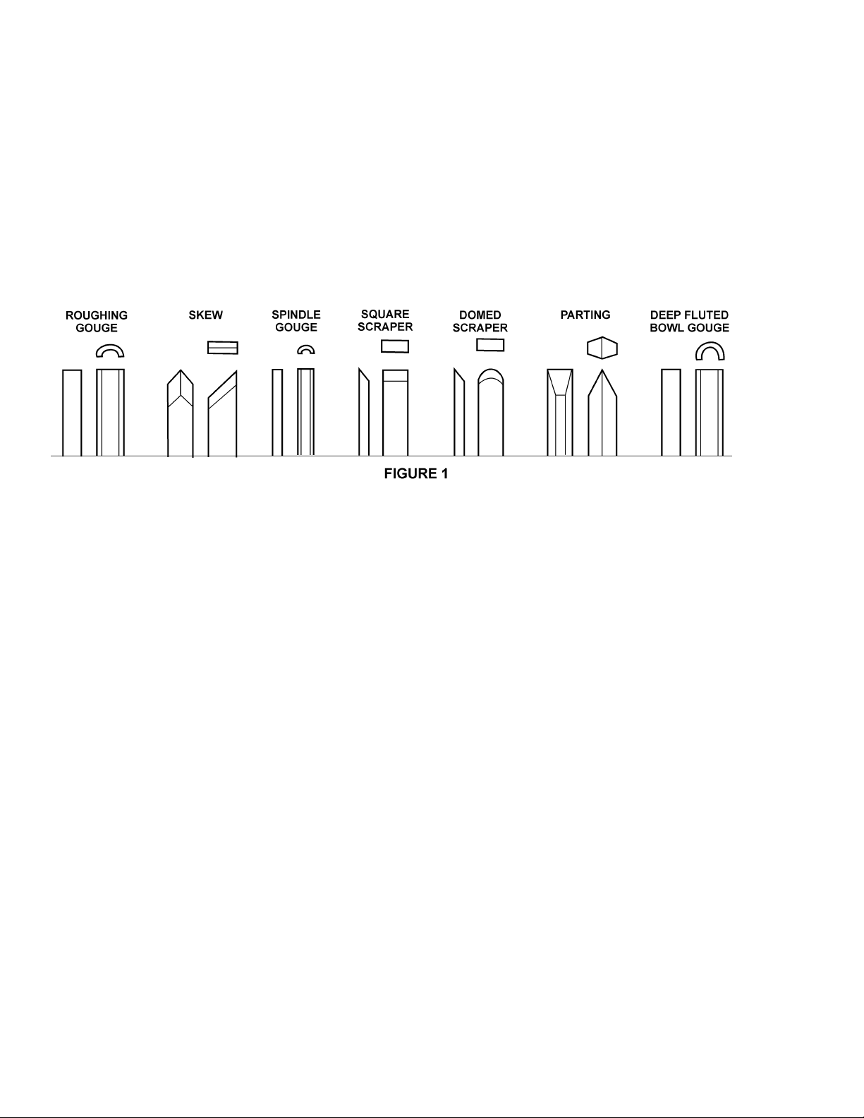
be acquired. The fol lowing tools provide the basics for most woodturning projects:
Large Roughing Gouge - 1" to 1-1/4", used to elimi nate waste wood.
Skews - 1-1/2" and 1" or 1- 1/4", used to m ak e finishing cuts and detai ls.
Spindle Gouges - 1/4", 3/8", 1/2", used to turn beads, coves and other details.
Square Scraper - 1/2", used to create square shoulders.
Large Domed S craper - 1-1/2", used to r educ e r idges on interior of bowls.
Parting Tool - 1/8", used to set diameters for sizing.
Deep Fluted Bowl Gouge - 1/4", 3/8" and 1/2", used for turning bowls & plates.
For safety and best performance, keep t ools sharp . If a tool stops cutting or requires excessiv e pr essure to make a
cut, it needs to be sharpened. A number of brand name sharpening ji gs and fixtures are available, however , a
woodturner should learn t o sharpen t ools freehand. For best results, use a slow speed grinder (1800 rpm) fitted with
a 60-grit wheel ( for shaping) and a 100-grit wheel (for final sharpeni ng and touchup). The gr inder should be located
near your lat he and at a comfortable height. A diamond dresser will keep the wheels true and eli minat e glazing.
Never allow the tool to rest in one place on the wheel, keep it m ovi ng and use a l ight touch.
Carbon steel tools can overheat easily and should be c ooled frequently. If the edge turns blue, i t has lost its temper
and should be ground past the blue ar ea. High-speed steel tools are not as lik ely to overheat, but can be damaged if
allowed to get r ed hot. High speed steel t ools should not be quenched for cooli ng. Honing with a diamond lap or
slipstone will save trips to the grinder and keep the edge fresh.
OPERATING INSTRUCTIONS
Before operating the lathe, check eac h tim e that everythi ng is in proper working or der :
1. Lev el your m ac hine: use the adjustable levelers to help reduce vibration.
2. Check bearings: adjust only i f endplay exists.
3. Check belt s: shoul d be snug but not over ly ti ght.
4. Ways - keep clean, use steel wool and wax to prevent buildup of rust and finishes.
5. Toolrest - use mill file to remove nicks and dings.
6. Spindl e tapers - should be clean and free of dust and chips for pr oper seat ing of t aper s. Clean with
scotchbrit e or taper cleaner.
7. Tailstock - cl ean and lubricate ram and l oc k ing device.
8. Lighting - proper lighting is essential.
9. Dust extr actor - to remove excess sanding dust.
10. Anti- fatigue mat - will help make long hours in fr ont of t he lathe mor e c omf or table.
10
Page 11
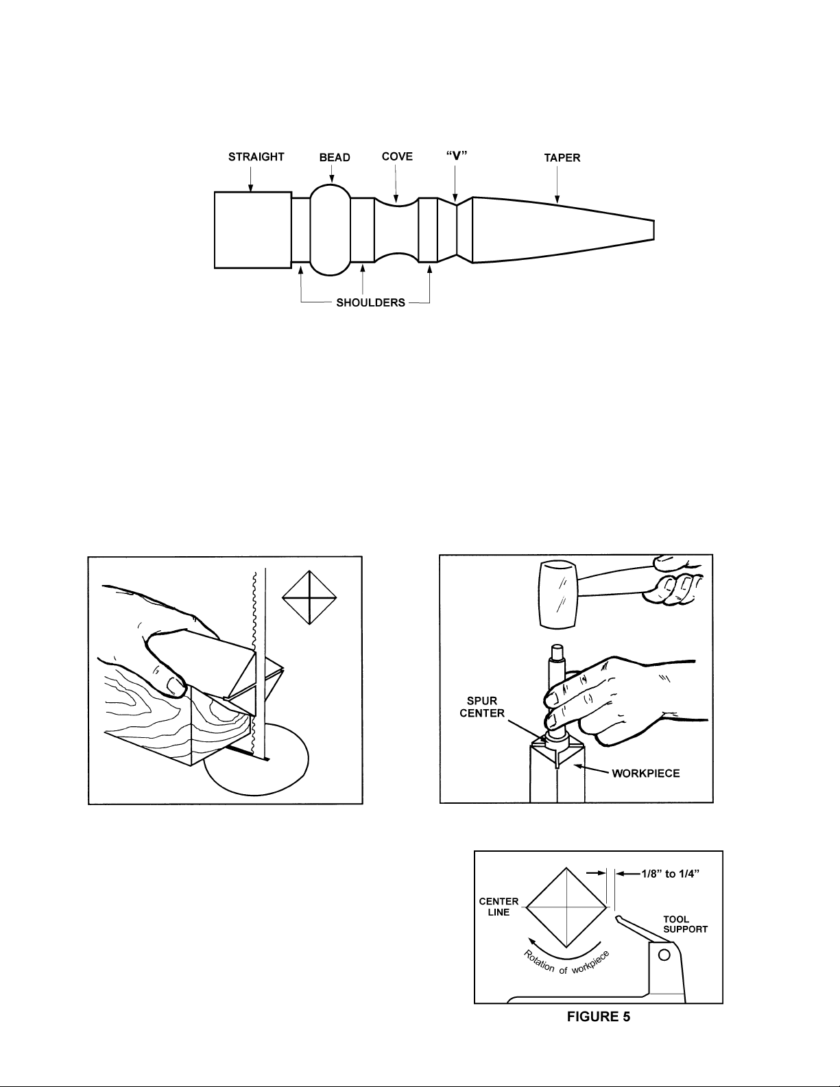
SPINDLE TURNING
Spindle t urning takes plac e between the centers of the lathe. It requir es a spur or drive center in t he headstoc k and
a revolving or live center in the tail st oc k . A cup center rather than a cone cent er will reduce the risk of splitting the
stock. Figure 2 shows the basic profi le shapes in spindle turning.
FIGURE 2
STOCK SELECTI O N
Stock for spindles should be straight grained and free of checks, crack s, k nots and other defec ts. It should be cut
1/8" to 1/4" larger than the finished diamet er and may require additional length to remove ends if requir ed. Larger
stock should have the corners remov ed to produce an octagon making the piece easier to rough down to a cylinder.
1. With a combinati on square or plastic center finder, loc ate and mark c enter on each end of stoc k . Accuracy is
not crit ical on full rounds but extremely import ant on stock where square sections are to remain. P ut a dimple in the
stock with an awl or nai l, or use a spring-loaded automat ic center punc h.
2. Extremely har d woods may r equire kerfs cut into the spur drive end of stoc k, Figur e 3, or may need to have the
spur center driven i nto the stock with a wood m allet or dead blow hammer , Figure 4. NOTE : Never use a steel face
hammer and never drive stock o nto spur while it is mounted in t he lathe spindle.
FIGURE 3 FIGURE 4
MOUNTING ST OCK
1. Install workpiece by inserting the att ac hed spur center
into the spindle taper on the headstoc k .
2. Bring tailstock into position, lock it to the bed, and
advance the spindle with the handwheel in order t o seat the
cup center into the workpiece.
3. Move tool support i nto position. It should be parallel
to the workpiece, just below the cent er line and approxim ately
1/8" to 1/4" from the corners of the workpiece to be t ur ned,
as in Figure 5. Lock tool support to bed.
11
Page 12

4. Rotate workpiece by hand to check f or pr oper clearance.
5. Start l athe at lowest speed and bring i t up to the appropriate RPM for the size of stock used (refer to table on
page 9).
CUTTING TECHNIQUES
ROUGHING OUT:
1. Begin with a large roughing gouge. P lace the tool on the tool support with the heel of the tool on the surfac e to
be cut.
2. Slowly and gently raise tool handle until cutt ing edge comes i nto contact wit h the workpiece.
3. Beginning at the tailstock end of the
workpiece, roll the flute ( hollowed-out
portion) of the tool in the directi on of the
cut, Figure 6. Make long sweeping cuts
in a conti nuous motion t o r ough the piece
down to a cylinder . Keep as much of the
bevel of t he tool as possible in contact
with the workpiece to ensure control and
avoid catches.
NOTE: Alw ays cut dow n-hill, or from
large diamet er to small d iameter.
Always work toward the end of a workpiece, never st art cuttin g at the end.
4. Once the workpiec e is roughed
down to a cylinder , smooth it with a large
skew. Keep the skew handle perpendicul ar
to the spindle and use only the center
third of the cutting edge f or a long smoothing
cut (touching one of t he points of t he skew to t he spi nning workpiece may cause a catch and rui n the workpiece).
6. Add detail s t o the workpiece with skew, parting tool, scraper or spindle gouge.
BEADS:
1. Make a parti ng c ut for what i s to be a bead to the desired depth. Place the par ting tool on the tool support and
move tool forward to m ak e the full bevel of the tool c ome in cont act with the workpi ec e. Gentl y r aise handle to make
cut to the appropriate depth.
2. Repeat for other side of the bead.
3. Using a small skew or spindle gouge, start in the center between the two cuts and cut down each side to form
the bead. Roll the tool in direct ion of c ut.
COVES:
1. Use a spindle gouge. Wit h the fl ute
of the t ool at 90 degrees to the workpiece,
touch the point of t he tool to the workpiece
and roll in towards the bottom of the cove,
Figure 7. Sto p at the bo tto m; attempting
to go up the opposite side may cause
the too l to catch.
2. Move the tool over the desi r ed wi dth
of the cove.
3. With the flute facing the opposite
direction, repeat step 1 for other si de of
cove. Stop at bottom of cut.
"V" CUTS:
1. Use the long point of the skew.
(NOTE: Do not press the long point of the
skew directly into the workpiece to create the "V"; this will result in a burned or burnished "V" with fi ber s bei ng rolled
up at both sides.)
12
Page 13

2. Lightly mark the c enter of t he "V" with the tip of the skew.
3. Move the point of the skew to the ri ght half of the desi r ed wi dth of your c ut.
4. With the bevel par allel to the right si de of the cut, raise the handle and push the tool in to the desired dept h, as
shown in Figure 8.
5. Repeat from the l eft side. The two cuts should meet at the bottom and leave a clean "V" cut.
6. Additi onal cuts may be taken to add to either the depth or width of the cut.
PARTING OFF:
1. Use parting tool .
2. Adjust lat he speed to lower RPM
for part ing through a workpiec e.
3. Place tool on tool support and r aise
the handle until it starts to cut and continue
to cut towards the cent er of the workpiece.
4. Loosely hold on to the piece in one
hand as it separates fr om the waste wood.
SANDING & FINIS HING:
Leaving clean cut s will reduce the
amount of sanding requir ed. Adjust the
lathe to a l ow speed, and begin with fine
sandpaper (120 grit or finer) . Coarser
sandpaper will leave deep scratches that
are dif fic ult to remove, and dull c r isp detail s
on the spindle. Progress through each grit
without skipping grits (e.g., do not j ump fr om 120 grit to 220 grit ) . Fold t he sandpaper into a pad; do not wrap
sandpaper around your fingers or the workpiece.
To apply a fini sh, the workpiece can be l eft on the lathe. Turn off the lat he and use a brush or paper towel to apply
the finish. Rem ove excess finish before restart ing lathe. Allow to dr y and sand agai n with 320 or 400 grit sandpaper.
Apply second coat of f inish and buff.
FACE PLATE & BOWL TURNING
Face plate turning i s normall y done on the inboard side of the headstock over the bed. Larger workpieces m ust be
turned on the outboard side (remove tailstock and t ool support, and move headstoc k to opposite end of bed).
MOUNTING STOCK
Use of a fac e plate is the most common method for holding a bloc k of wood for t ur ning bowls and plates:
1. Select stoc k at least 1/8" t o 1/4" larger than each dimension on the f inished workpiece.
2. Always select the largest diam eter fac e plate that c an be
used for the workpi ec e to be turned.
3. True one surfac e of the workpiec e for mounting agai nst the
face pl ate.
4. Using the fac e plate as a tem plate, mark the l oc ation of the
mounti ng holes, and drill pilot holes of the appropriate size. Face
plates are drilled for No. 12 screws. (Phillips and square drive
screws will hold up better than slotted screws. Sheel metal screws
are
case hardened with deeper and sharper threads than wood
screws.)
If t he mounti ng screws on the face plate interfere with the
workpiece, a gl ue or waste bloc k c an be used:
13
Page 14

5. Make a block the same diameter as the face plate, Figure 9. B oth glue block and workpiece should have good
flat surfaces for gluing.
6. Glue the block to the workpiece. Avoid using br own paper or newspaper between the bloc k and workpiece. It
may work fine if you are using scrapers, but a slight catch with a bowl gouge can separate t he two.
NOTE: When using a glue block, be c areful with the adhesive you select. Dry workpieces can be bonded with
ordinary whit e or y ellow glue but must be clamped to ensure a good bond. Gr een workpieces require cyanoac r y late
(super glue).
FACEPLATE OR CHUCK?
While faceplates are t he si mplest, most reliable m ethod of hol ding a block of wood for t urning, chuck s can also be
used. As there are dozens of c huc k s to c hoose from, the woodturner should first consider all the different ty pes of
turning that will be done, and read reports or discuss with other turners who own chucks before making a deci si on.
A chuck is not a r equirement but is handy when working on more than one piece at a time. Rather than removing
screws, you simply open the chuck and change workpiec es. The most popul ar ones are four jaw scroll chucks with a
variety of jaws to accomodate different si z e tenons. Most also com e with a screw chuck as well.
WOOD SELECTION
Firewood is the cheapest, most widel y avai lable stock to use while learni ng to turn bowls. Si mply waste wood for a
while practicing tur ning techni ques. Devel op skill with each tool before attempting to make a finished piece. I t is best
to start with dr y wood, wit hout worrying about dry ing or distortion. Onc e turning becomes comfortable, try green
wood which cuts very easi ly. As the t ur ner gains experience, he or she will find extraordinary grain and figure in the
form of burls, crotches and bark inclusions.
CHECKS & CRACKS
Green wood will check and crack. For best resul ts, leave logs in as long lengths as you can handle. A s the material
starts to dry, surface cracks will develop on the ends of t he log. Cut off two to three inches and you should find
good, sound wood. Also cut the log in half along the pith to avoid having it i n the fi nished piece. Most c hec k s
radiate from the pith. A s you t urn bowls from gr een wood, make sure you maintain a c onsi stent wall thickness
throughout the piece. Leaving a pi ec e thick in some areas and thin in others will cause the wood to dry unevenl y
and promote checks and cracks.
DISTORTION
Distortion is a problem associated with tur ning green wood. It will vary from one type of wood to the next. T y pically,
frui twoods tend to distort more than other s do. It also varies with t he time of year t he tree was cut and how the logs
are stored.
TOO LS FOR BOWL TURNING
The deep fluted bowl gouge is the most essential and versati le tool for m ost bowl and facepl ate style turning. The
bowl gouge is heav ier and easier to control than other types of gouges. It also allows removal of wood m uc h faster
and with less v ibration than other gouges. Most average sized bowl work can be ac c omplished with a 3/8" or 1/2"
bowl gouge. A 1/4" bowl gouge is best suited for smaller bowl s and l ight f inishing cuts. Larger 3/4" and 1" bowl
gouges are only used for extremely l ar ge pieces.
Large domed scrapers can al so be used to hel p c lean up the interior surfaces of bowls. A light touch with the scraper
slightly tilted will eliminate some of the ridges occasionally left by an inexperienced bowl gouge.
BOWL TURNING T ECHNIQUES
TO SHAPE OUTSIDE OF BOWL:
1. Odd shaped burls, crot c hes and other irregular shaped bl ank s require special pr epar ation bef ore mounting in a
chuck or onto a faceplat e. Remove the bark, if there is any, from what appears to be the center of the top of the
workpiece.
2. Drive spur center i nto the top of the workpiece wit h a mallet or dead blow hammer.
3. Slip t he spur c enter into t he headstoc k taper and bring t he tailstoc k with a live or ball bearing c enter into
position. Lock the tai lstock to t he bed and advance t he spi ndle in order to seat the cup center into the workpi ec e.
Tighten the quill lock.
4. Position tool support below the centerli ne and about 1/4" f rom the workpi ec e. (NOTE: For larger outboard
turning, an optional outboard turning stand is used to place the t ool support; see your Powerm atic deal er ) .
14
Page 15

5. Turn workpiece by hand to ensure proper clearanc e.
6. Start l athe at lowest speed and bring i t up to the maximum safe speed for the si z e of work to be tur ned ( see
chart on page 9). If the machine starts to v ibrate, lower the speed until vi bration stops.
7. Rough out the outside of the bowl with the 1/2" deep fluted bowl gouge, holding the tool f irmly against your hip.
For best control, use your whole body to move the gouge through the workpiece.
8. As bowl takes shape, work on the bottom (tailstock end) to acc omodate attaching a face plate.
9. Turn a short tenon (about 1/8" long) the size of the hole in t he facepl ate, Figur e 10. This will allow centering the
workpiece when the fac eplate is att ac hed. (NOTE: If y ou plan to use a chuck, turn a tenon of the appropriat e length
and diamet er to fit your chuck .)
10. Stop the lathe, rem ove workpiece
and attach face plate or c huc k ( see
"Mounting S tock" above).
11. Finish turning the outsi de of bowl
with 1/2" or 3/ 8" bowl gouge. Leav e
additional mat er ial at base of bowl for
support while turning interior. This will
be removed lat er .
TO SHAPE INTERIOR OF BOWL:
1. Stop lathe and move tailstock away.
Remove center from tailstoc k to prev ent
bumping it with el bow.
2. Adjust tool support in front of the
bowl just below centerline, at a r ight angle
to the lathe ways.
3. Rotate workpiece by hand to check
clearance.
4. Face off top of bowl by mak ing a li ght shearing cut across the t op of workpiece, from rim to center.
5. Place 1/2" bowl gouge on toolrest at center of the workpiece with t he flut e faci ng top of bowl. The tool handle
should be level and poi nted toward four o'clock, as shown in Fi gure 11.
6. Use left hand to control c utting edge
of gouge, while right hand swings tool
handle around toward your body ( see
Figure 11). The flute should start out
faci ng top of workpi ec e, and rotate
upward as it moves deeper into the bowl
to mai ntain a cl ean even curve.
As tool goes deeper int o bowl,
progressively work out toward rim. It may
be necessary to turn the t oolrest into the
piece as you get deeper into the bowl.
(NOTE: Try to make one, very light
continuous movement f r om the rim to t he
bottom of the bowl t o ensure a clean,
sweeping curve through the piece. Should
there be a few small ri dges l eft, a light
cut with a l ar ge domed scraper can even
out the surfac e.)
7. Develop wall thickness at the rim and maintain it as you work deeper into t he bowl ( Once the piece is thin
toward the bottom, you cannot make it thinner at the rim ). When the int er ior is finished, move tool support t o exterior
to re-def ine bottom of bowl. ( General rule of thumb: the base should be approximately 1/3 the overall diameter of
the bowl).
8. Wor k the tight ar ea ar ound facepl ate or chuck with 1/ 4" bowl gouge.
9. Begin the separation with a parting tool, but do not cut al l the way through yet .
15
Page 16

SANDING AND FINISHING:
1. Remove the toolrest and adjust lathe speed to approximately 500 RPM. Hi gh speed can build friction while
sanding and cause heat check i n some woods.
2. Begin with fine sandpaper (120 grit) and progress through each grit, using only li ght pressure. Coarser
sandpaper tends to leave deep scratches that ar e har d to eliminate. Use power-sanding techniques to avoid
concentric sanding marks around your fi nished piece. Avoi d r ounding ov er the rim and foot with sandpaper; try t o
keep detail s cr isp. Finish sanding with 220 grit .
3. Remove sanding dust with tac k r ags or c ompressed air and, with lathe turned off , apply first coat of finish. Let
stand for several minutes, wipe off excess. Allow to dry before sandi ng again with 320 or 400 grit sandpaper.
4. Turn lathe back on and continue the separation cut almost al l the way through the base. S top at about 3" and
use a small fine tooth saw to separate the bowl from the waste.
5. Apply second finish coat and allow to dry before buf fing.
16
Page 17

TROUBLE-SHOOTING (3520A Lathe)
PROBLEM POSSIBLE CAUSE SOLUTION
Excessive vibration. 1. Defective spindle bearings. 1. Replace bearings.
2. Worm or defective belt. 2. Replace bel t.
3. Defective mot or . 3. Replace motor.
4. Workpiece warped, out-of-round, 4. Correct problem by plani ng
has major flaw, or was improperly or sawing, or scrap workpiece.
prepared for turning.
Motor or spindle stalls. 1. Excessive cut . 1. Reduce cut depth.
2. Defective mot or . 2. Replace motor.
3. Excessive bel t wear. 3. Replace belt.
4. Impr oper belt adj ustment. 4. Readjust belt.
Motor overheats. 1. Motor overl oaded. 1. Correct overload condition,
such as reducing cut depth.
2. Impr oper cooling on motor. 2. Clean sawdust from fan and
duct areas of motor.
Motor starts slowly or 1. Low voltage. 1. Request v oltage check from
fails to come up to speed. power company and correc t
low voltage condition.
2. Defective mot or . 2. Replace motor.
Motor f ails to develop full 1. Power line overloaded. 1. Correct over load condition.
power. 2. Undersize wires in suppl y system. 2. Increase supply wire size.
3. Low vol tage. 3. Request vol tage check from
power company and correc t
low voltage condition.
4. Defective mot or . 4. Replace motor.
Tools tend to gr ab or dig in. 1. Dull tools. 1. Sharpen tool s.
2. Tool support set too low. 2. Reposition tool support hei ght.
3. Tool support set too far from workpiece. 3. Reposit ion tool support c loser
to workpiece.
4. Impr oper tool bei ng used. 4. Use corr ec t tool for operation.
Lathe runs at one speed. 1. Elect ronic AC i nverter defective, not 1. Replace el ectronic A C inverter,
programmed properly or loose wiring. reprogram, or check wir ing.
Headstock moves when 1. Excessive pressure being applied by 1. Sl ide headstock down the left
applying pressure with tailstock (more than 500 lbs. of force) si de of the l athe against the
tailstock. NOTE: The screw action of the tailstock stop then apply pr essure to
is capable of applyi ng excessive pressure workpiece with tailstock.
to workpiece and headstock. Apply onl y
sufficient force by tailstock to hold work piece securely in place. E xcessive
pressure can cause damage to m ac hine.
17
Page 18

PARTS LIST: Headstock A ssembly (3520A Lathe)
No. Part No. Descrip t ion Quantity
2277128 Headstock Assembly ........................................................................................ 1
1 6294792 Headstock ........................................................................................................1
2 3719189 Motor Sheave...................................................................................................1
3 2595036 Mot or A ssem bly Plat e.......................................................................................1
4 6294793 Mot or , 2HP, 220V, 60Hz...................................................................................1
5 6350031 Mot or P late Locking Handle..............................................................................1
6 6060014 Bearing.............................................................................................................1
7 6430045 Knob.................................................................................................................2
8 6716139 Flat Head Socket Screw, 3/8-16 x 1..................................................................4
9 6714159 Sock et Set Screw, 1/ 4- 20 x 3/8.........................................................................2
10 6861300 Lock Washer, 3/8..............................................................................................3
11 6716012 Socket Head Cap Screw, 3/8-16 x 1 .................................................................3
12 3271081 Handwheel........................................................................................................1
13 6714160 Slotted Head Steel Set Scr ew, 1/ 4- 20 x 1/4 ......................................................2
14 6549006 Bearing Lock Nut..............................................................................................1
15 6864006 Bearing Lock Washer .......................................................................................1
16 6060185 Bearing.............................................................................................................1
17 3708013 Headstock Clamping Shaft ...............................................................................1
18 6095038 Bushing ............................................................................................................1
19 3268219 Headstock Handle ............................................................................................1
21 6294780 Invert er (Program med 3520A) ..........................................................................1
22 6760070 Socket Head Cap Screw, 10/32 x 5/8.............................................................10
23 3064711 Lathe Guard Bracket.........................................................................................1
24 6143004 Retaining Collar................................................................................................2
25 6714003 Socket Set Scr ew, 1/ 4- 20 x 3/8.........................................................................2
26 6644005 Plunger.............................................................................................................1
27 6296165 Flat Washer, 3/8 x 3/4 x 1/16 Thk.....................................................................2
29 6294728 Guard Assembly...............................................................................................1
30 6295930 Head Spindle....................................................................................................1
31 3388100 Key, 5/16..........................................................................................................1
32 6294725 Spur Center 1", MT 2.........................................................................................1
33 TS-0270011 S oc k et Set Screw, 5/16-18 x 1/4.......................................................................2
34 6295915 Control Pot .......................................................................................................1
35 3578349 Control Panel....................................................................................................1
36 6295923 Clamp Washer..................................................................................................1
37 TS-0810012 P an Head S c r ew, #10-32 x 1/4 ......................................................................... 1
38 6430047 Control Panel K nob...........................................................................................1
39 6294794 Push/Pull Switch...............................................................................................1
40 6601000 "O" Ring ........................................................................................................... 1
41 6294781 Lock Knob ........................................................................................................1
42 6295911 Pad...................................................................................................................1
43 3578348 Door Panel .......................................................................................................1
44 6508007 Nut ...................................................................................................................2
45 6860704 Lock Washer ....................................................................................................2
46 6365012 Door Hinge.......................................................................................................1
47 6708019 Socket Head Cap Screw, 8/32 x 5/8..................................................................4
48 6520009 Flex Lock Nut, 5/8-11 .......................................................................................1
49 3092093 Head Clamp ..................................................................................................... 1
50 3058001 Tool Support Clamp Bol t...................................................................................1
51 6760102 Socket Set Scr ew, 10/ 32 x 1.............................................................................1
52 3719188 Spindle Sheave ................................................................................................1
53 6077228 Micro V Bel t......................................................................................................1
6294743 Knockout Rod Assembl y ( Items 55 & 56).......................................................... 1
55 3670021 Knockout Rod...................................................................................................1
56 3406201 Teardrop Knob..................................................................................................1
57 6083021 Contact Block ...................................................................................................1
18
Page 19

PARTS LIST: Headstock A ssembly (3520A Lathe) continued
No. Part No. Descrip t ion Qu a ntity
58 6821492 FWD/REV Switch............................................................................................. 1
59 6860800 Plain Flat Washer, #10 ..................................................................................... 1
60 6294782 Hex Nut............................................................................................................ 1
61 3448048 Lock Plate........................................................................................................1
62 6813062 Compression Spring......................................................................................... 1
63 3601006 Spindle Lock Plunger ....................................................................................... 1
64 3097007 Locking Collar..................................................................................................1
65 6715015 Socket Head Set Scr ew, 5/ 16- 18 x 1/4............................................................. 2
66 6294783 Motor Label......................................................................................................1
67 6294784 Speed Label..................................................................................................... 1
68 6294785 Control Panel Label.......................................................................................... 1
69 6294736 3" Face Plate, 1-1/4-8 ......................................................................................1
70 6294786 Spindle Lock Br ac k et ....................................................................................... 1
71 6294787 Power Cord...................................................................................................... 1
72 6294788 Control Cord..................................................................................................... 1
73 6294744 Face Plate Wrench .......................................................................................... 1
75 6294789 Motor Key ........................................................................................................1
76 6294790 Motor Cord....................................................................................................... 1
77 6294791 Hex Nut............................................................................................................ 2
78 6295733 Brake Resistor.................................................................................................. 1
79 TS-0640091 Ny lon Lock Hex Nut, 3/8-16.............................................................................. 1
80 TS-1502071 S oc k et Head Cap Screw, M5 x 30.................................................................... 1
81 TS-1550031 Flat Washer, M5 .............................................................................................. 1
82 TS-1540031 Nut, M5............................................................................................................1
83 6295912 Clamp .............................................................................................................. 1
84 6295913 Clamp PG16 ....................................................................................................2
85 6295914 Clamp PG11 ....................................................................................................1
86 6295796 Nylon Set Screw, 1/ 4- 20 x 3/8..........................................................................2
87 6860802 Lock Washer, #10 ............................................................................................ 2
19
Page 20

Headstock Assembly (3520A Lathe)
20
Page 21

PARTS LIST: Stand & Bed Assembly (3520A Lathe)
No. Part No. Description Q u anti ty
1 6295920 Bed ..................................................................................................................... 1
2 3423053 Lathe Leg............................................................................................................ 2
3 6716012 Socket Head Cap Screw...................................................................................... 2
4 3761159 Stop Block........................................................................................................... 2
5 6294752 Tool Support A ssembly (Consists of items 7, 8, 10, 14, 31, 48, 49, 51)................ 1
6 6294742 Tool Support 14" ................................................................................................. 1
7 6294756 Snap Ring ...........................................................................................................2
8 6294757 Tool Support Clamp Shaft................................................................................... 1
10 6294759 Tool Suppor t Clamp B olt ..................................................................................... 1
14 6294763 Tool Rest Handle................................................................................................. 2
16 6295907 Tailstock.............................................................................................................. 1
17 6295908 Tailstock Quill ..................................................................................................... 1
18 6295902 Live Center Assembly (Consists of item s 52, 53, 54, 55)..................................... 1
19 3728005 Quill Lock Sleeve................................................................................................ 1
20 6295910 Tailstock Quill Handle .........................................................................................1
21 6760102 Socket Set Screw, 10/32 x 1................................................................................ 1
22 6623086 Dowel Pin............................................................................................................ 1
23 6295909 Quill Lead Screw.................................................................................................1
26 6295918 Handwheel.......................................................................................................... 1
28 6715013 Socket Set Screw, 5/16-18 x 3/8.......................................................................... 3
29 3708012 Tailstock Clamping Shaft..................................................................................... 1
30 6294769 Hex Nut............................................................................................................... 1
31 6095038 Bushing...............................................................................................................2
32 3268217 Tailstock Handle.................................................................................................. 1
33 6430045 Black Knob.......................................................................................................... 1
34 3096003 Collar ..................................................................................................................1
37 6294772 Lock Washer....................................................................................................... 8
38 6295792 Socket Head Cap Sc r ew, 3/ 8- 16 x 1-1/4.............................................................. 8
39 6516009 Hex Jam Nut Plain, 3/8-16 .................................................................................. 4
40 6442000 Reid Leveler........................................................................................................ 4
41 6294773 Warning Label..................................................................................................... 1
42 6294774 Powermatic Name Plate...................................................................................... 1
43 6294775 I.D. Label ............................................................................................................ 1
44 6295751 Handle ................................................................................................................ 1
47 3058001 Tailstock Clamp Bolt ........................................................................................... 1
48 3092095 Tailstock/Toolrest Clamp..................................................................................... 2
49 6520009 Flex Lock Nut, 5/8-11.......................................................................................... 2
51 6295899 Tool Suppor t Base............................................................................................... 1
52 6295903 Live Center Body................................................................................................. 1
53 6295904 Live Center Tip.................................................................................................... 1
54 6295905 Live Center Cap .................................................................................................. 1
55 6295906 Live Center Rod .................................................................................................. 1
21
Page 22

Stand & Bed Assembly (3520A Lathe)
22
Page 23

OPTIONAL ACCESSORIES: Indexer & Bed Extensions (3520A Lathe)
No. Part No. Description Quantity
6294729 Indexing A ssem bly (Items 1 thru 5)
1 3097006 Indexing Collar..................................................................................................1
2 3406005 Adjusting Screw Knob.......................................................................................1
3 3585220 Indexing Pin......................................................................................................1
4 6714139 Socket Set Screw, 1/4-20 X 5/8.........................................................................2
5 TS-0267021 Socket Set Screw, 1/ 4- 20 x 1/4.........................................................................1
6294727 18" Short Bed Extension (Items 6 thru 9)
6 TS-0680041 Flat Washer, 3/8 ...............................................................................................3
7 6295921 Short Bed .........................................................................................................1
8 6716017 Socket Head Cap Screw, 3/8-16 x 1-3/4............................................................3
9 6861300 Lock Washer, 3/8..............................................................................................3
6294726 50" Full B ed E xtension (I tems 6 & 8 thru 14)
6 TS-0680041 Flat Washer, 3/8 ...............................................................................................3
8 6716017 Socket Head Cap Screw, 3/8-16 x 1-3/4............................................................3
9 6861300 Lock Washer, 3/8..............................................................................................7
10 6516009 Plain Hex J am Nut, 3/ 8-16................................................................................2
11 6295920 Long Bed..........................................................................................................1
12 3423053 Lathe Leg..........................................................................................................1
13 6442000 Leveler .............................................................................................................2
14 6716015 Socket Head Cap Screw, 3/8-16 x 1-1/2............................................................ 4
15 6294734 Spindle Adapter, 1-1/4"-8 t o 1- 1/2"-8
16 6294735 2" Spindle Extension
23
Page 24

OPTIONAL ACCESSORIES: Indexer & Bed Extensions (3520A Lathe)
24
Page 25

OPTIONAL ACCESSORIES: Tool Supports (3520A Lathe)
No. Part No. Description
1 3585011 Tool Support P in 5/8 X .495 X 3.50
2 6294745 Ball Bearing Tailstock Center (not shown)
4 6294730 12" Metal Spinning Tool Support Assembl y (Item s 1 and 4)
6294731 26" Tool Support Assembly (Items 6 thru 8)
7 6294795 Tool Support P ost
8 6716219 Socket Head Cap Screw, 3/8- 16 x 6-1/4
9 6294740 Bowl Turning Tool Support, R.H.
10 6294751 Bowl Turni ng Tool Support, L.H.
11 6294741 16" Tool S uppor t
12 6294739 6" Tool S uppor t
6294742 14" Tool Support
25
Page 26

OPTIONAL ACCESSORY: Outboard Turning Stand (3520A Lathe)
No. Part No. Description
6294732 Heavy Duty Outboard Turni ng S tand (Items 1 thru 9)
1 3042503 Turning Stand B ase
2 6295897 Offset Tool Suppor t Pin, 1.00 dia.
3 6295898 Offset Tool Suppor t Casting 1.00 hole
4 2695026 Screw Lock Assembly
7 3423055 Turning Stand S c r ew Leg
8 6861700 Lock Washer, 5/8
9 6769002 Socket Head Cap Screw, 5/8- 18 x 2
26
Page 27

OPTIONAL ACCESSORIES (3520A Lathe)
No. Part No. Description
1 6294736 3" Face Plat e, 1-1/4-8 (STD.)
2 6294737 4" Face Plat e, 1-1/4-8 (O P T.)
3 6294738 7" Face Plat e, 1-1/4-8 (O P T.)
4 6294744 Face Plate Wrenc h
OPTIONA L ACCESSORY
Part No. Descriptio n
6294733 Remote ON/OF F Switch
OPTIONAL ACCESSORIES
Part No. Descriptio n
6294725 Spur Center, 1"
6294728 Guard Assembly
6294743 Knock Out Rod
27
Page 28

ELECTRICAL SCHEMATIC: 3520A Lathe
28
Page 29

ELECTRICAL: Remote ON/OFF Switch (Optional)
NOTE:
The lathe can only operate when both the
headstock and remote switches are in the
"ON" position.
STEP 1:
Disconnect all elect r ical power to lathe.
STEP 2:
Remove the two screws from the control panel.
Do NOT disconnect control panel from wiring harness.
STEP 3:
Run the remot e swit c h' s wiring harness through the opening in the back of the headstock and out through
the front of t he headstoc k .
STEP 4:
Connect the remote switch wiri ng harness to the back of the Push/Pull switch
(Refer to the elect r ical schematic on page 29).
STEP 5:
Reinstall the control panel to the headstock.
From t he back of t he headstoc k , lightly pull out any excess wire that may be inside the headstock.
STEP 6:
The magnetic back on the r emote switch will allow the switch to be placed anywhere on the lathe.
STEP 7:
Connect elect rical power to the lathe and resume operation.
29
Page 30

ELECTRICAL SCHEMATIC: 3520A Lathe with Remote Switch (Optional)
30
Page 31

ELECTRICAL SCHEMATIC: 3520A School Lathe (#1352002)
31
Page 32

ELECTRICAL SCHEMATIC: 3520A School Lathe - 2330009 Kit
32
Page 33

AC INVERTER READINGS: Lathe Speed Chart
33
Page 34

Instructions for Mounting Indexing Assembly (Optional Accessory)
1. Remove the handwheel. Loosen the two set screws and slide the handwheel off.
2. If your l athe was purchased before January 1998, you must drill a 1/4" hole into the headstock so that
the index er will work properly. Before the 1/ 4" hole can be dri lled you must first make sure t hat the 1/4"
hole will line up with the holes in the indexer. To do thi s you will need a small center punch that can be
placed through one of the tapped holes in the indexer. I nstall the indexer ont o the spindle. Slide the
indexer up to the headstock l eavi ng approximately an 1/8" gap between the f ac e of the indexer and the
headstock. (The hub of the i ndexer, which has the two set screw holes, should be pointing away from
the headstock.) Usi ng one of the tapped holes in the i ndexer as a guide, place the center punc h
through one of the holes in the indexer. With a hammer, strike the end of the center punc h making a
mark on the headst oc k .
3. Remove the index er from the spindle.
4. Using a 1/4" drill bit, drill a hole at the mark made by the center punch.
5. Install the indexer ont o the spindle. S lide the indexer up to the headstock leaving appr oximately an 1/8"
gap between the face of the i ndexer and the headstock.
6. Locate one of the set screws on the indexer over the keyway slot on the spindle. Tighten securel y both
set sc rews.
7. Install i ndexing pi n into the indexer by screwing it int o one of the tapped holes. The indexing pi n k nob
should be turned until the i ndexing pi n engages t he 1/4" drilled hole. Tighten i ndexing pin securely.
8. Remove indexi ng pin from indexer before o perating lathe!
34
Page 35

To order parts or reac h our servi c e depar tment, please call our toll-free number between 8:00 a.m . and 4:30 p.m.
(CST), M onday through Friday . Hav ing the Model Number and Serial Number of your machine available when you
call will allow us to serve you quickly and accurately. Locating the stock number of the part(s) required fr om your
parts manual will also expedit e y our or der .
Phone No.: (800) 248- 0144
Fax No. (800) 274-6840
If you ar e c alli ng from Canada, please call 800-238-4746
E-mai l: powermat ic@wmht oolgroup.com
Webs ite: www.power ma tic.com
35
Page 36

03/03
WM H Tool Group
427 Sanford Rd.
LaVergne, TN 37086
Phone:(800) 248-0144
Fax: ( 800) 274-6840
E-mai l: powermat ic@wmht oolgroup.com
Webs ite: www.power ma tic.com
Powermatic ALL RIGHTS RESERVED
36
 Loading...