

Page 1

BELT & DISC SANDER
Model 31A
Instruction Manual & Parts List
M-0460267
(800) 274-6848
www.powermatic.com
Page 2

This manual has been prepared for the owner and operators of a Powermatic Model 31A Belt & Disc
Sander. Its purpose, aside from machine operation, is to promote safety through the use of accepted
correct operating and maintenance procedures. Completely read the safety and maintenance
instructions before operating or servicing the machine. To obtain maximum life and efficiency from
your sander, and to aid in using the machine safely, read this manual thoroughly and follow all
instructions carefully.
Warranty & Service
The WMH Tool Group warrants every product it sells. If one of our tools needs service or repair, one of our
Authorized Repair Stations located throughout the United States can give you quick service.
In most cases, any one of these WMH Tool Group Repair Stations can authorize warranty repair, assist you in
obtaining parts, or perform routine maintenance and major repair on your JET, Performax, Powermatic or Wilton
tools.
For the name of an Authorized Repair Station in your area, please call 1-800-274-6848.
More Information
Remember, the WMH Tool Group is consistently adding new products to the line. For complete, up-to-date product
information, check with your local WMH Group distributor.
WMH Tool Group Warranty
The WMH Group (including JET, Performax, Powermatic and Wilton brands) makes every effort to assure that its
products meet high quality and durability standards and warrants to the original retail consumer/purchaser of our
products that each product be free from defects in materials and workmanship as follow: 1 YEAR LIMITED
WARRANTY ON ALL PRODUCTS UNLESS SPECIFIED OTHERWISE. This Warranty does not apply to defects
due directly or indirectly to misuse, abuse, negligence or accidents, normal wear-and-tear, repair or alterations
outside our facilities, or to a lack of maintenance.
THE WMH TOOL GROUP LIMITS ALL IMPLIED WARRANTIES TO THE PERIOD SPECIFIED ABOVE, FROM THE
DATE THE PRODUCT WAS PURCHASED AT RETAIL. EXCEPT AS STATED HEREIN, ANY IMPLIED
WARRANTIES OR MERCHANTIBILITY AND FITNESS ARE EXCLUDED. SOME STATES DO NOT
ALLOW LIMITATIONS ON HOW LONG THE IMPLIED WARRANTY LASTS, SO THE ABOVE LIMITATION MAY
NOT APPLY TO YOU. THE WMH TOOL GROUP SHALL IN NO EVENT BE LIABLE FOR DEATH, INJURIES TO
PERSONS OR PROPERTY, OR FOR INCIDENTAL, CONTINGENT, SPECIAL, OR CONSEQUENTIAL DAMAGES
ARISING FROM THE USE OF OUR PRODUCTS. SOME STATES DO NOT ALLOW THE EXCLUSION OR
LIMITATION OF INCIDENTAL OR CONSEQUENTIAL DAMAGES, SO THE ABOVE LIMITATION OR EXCLUSION
MAY NOT APPLY TO YOU.
To take advantage of this warranty, the product or part must be returned for examination, postage prepaid, to an
Authorized Repair Station designated by our office. Proof of purchase date and an explanation of the complaint must
accompany the merchandise. If our inspection discloses a defect, we will either repair or replace the product, or
refund the purchase price if we cannot readily and quickly provide a repair or replacement, if you are willing to accept
a refund. We will return repaired product or replacement at WMH's expense, but if it is determined there is no defect,
or that the defect resulted from causes not within the scope of WMH's warranty, then the user must bear the cost of
storing and returning the product. This warranty gives you specific legal rights; you may also have other rights which
vary from state to state.
The WMH Tool Group sells through distributors only. Members of the WMH Group reserve the right to effect at any
time, without prior notice, those alterations to parts, fittings, and accessory equipment which they may deem
necessary for any reason whatsoever.
2
Page 3

TABLE OF CONTENTS
Safety Rules ............................................................................................................................................................... 4-5
Safety Decal .................................................................................................................................................................. 6
Specifications ................................................................................................................................................................ 7
Receiving....................................................................................................................................................................... 8
Installation & Assembly ................................................................................................................................................. 8
Electrical Connections ............................................................................................................................................ 8
Adjustments................................................................................................................................................................... 9
Abrasive Belt Installation ........................................................................................................................................ 9
Abrasive Belt Alignment.......................................................................................................................................... 9
Platen Adjustment................................................................................................................................................. 10
Sanding Table Adjustment.................................................................................................................................... 10
Work Stop ............................................................................................................................................................. 10
Belt Arm Positioning ............................................................................................................................................. 11
Changing Motor Voltage ....................................................................................................................................... 11
Operating the Sander.................................................................................................................................................. 11
Template Forms.................................................................................................................................................... 11
Fence/Table.......................................................................................................................................................... 12
Types of Operations ............................................................................................................................................. 13
Maintenance................................................................................................................................................................ 13
Lubrication ............................................................................................................................................................ 13
Grit Comparison Chart ................................................................................................................................................ 14
Accessories ................................................................................................................................................................. 14
Troubleshooting........................................................................................................................................................... 15
Parts Lists & Exploded Views: ...............................................................................................................................16-20
Body Assembly ................................................................................................................................................ 16-18
Stand Assembly............................................................................................................................................... 19-20
Electrical Schematics ............................................................................................................................................. 20-23
3
Page 4

!
SAFETY RULES
As with all machines, there is a certain amount of hazard involved with the use of this sander. Use the machine with
the respect and caution demanded where safety precautions are concerned. When normal safety precautions are
overlooked or ignored, personal injury to the operator can result.
Read, understand and follow the safety and operating instructions found in this manual. Know the limitations and
hazards associated with this machine.
Electrical grounding. Make certain that the machine frame is electrically grounded and that a ground lead is
included in the incoming electrical service. In cases where a cord and plug are used, make certain that the
grounding plug connects to a suitable ground. Follow the grounding procedure indicated in the National Electrical
Code.
Eye safety. Wear an approved safety shield, goggles, or glasses to protect eyes. (NOTE: Common eyeglasses are
only impact-resistant, they are not safety glasses.)
Personal protection. Before operating the machine, remove tie, rings, watch and other jewelry and roll up sleeves
above the elbows. Remove all loose outer clothing and confine long hair. Protective type footwear should be used.
Where the noise exceeds the level of exposure allowed in Section 1910.95 of the OSHA Regulations, use hearing
protective devices. Do not wear gloves.
Guards. Keep the machine guards in place at all times when the machine is in use. If removed for maintenance
purposes, use extreme caution and replace guards on completion of the maintenance task before operating the
sander. DO NOT operate the machine with the guards off except for the belt end guard which swings away to allow
for contour sanding. Keep that guard in place except when contour sanding and swing it back into position
immediately after completing the contour sanding task.
Work area. Keep the floor around the machine clean and free of scrap material, saw dust, oil and other liquids to
minimize the danger of tripping or slipping. Make certain the work area is well lighted and that a proper exhaust
system is used to minimize dust. Powermatic recommends the use of anti-skid floor strips on the floor area where
the operator normally stands and that each machine’s work area be marked off. Provide adequate work space
around the machine.
Avoid accidental starting: Make certain motor switch is in off position before connecting power to the machine.
Operator position. Maintain a balanced stance and keep your body under control at all times. Do not over-reach.
Do not stand in line with the belt in the direction that it is moving when the work stop is not in use.
Belt and Disc Direction. Proper belt direction is from the idler pulley towards the drive pulley. Proper disc rotation
is counterclockwise facing the disc. CAUTION: Sand on the section of the disc from the center to the left edge. DO
NOT use the right hand portion for sanding.
Housekeeping. Before turning on machine, remove all extra equipment such as keys, wrenches, scrap, and
cleaning rags away from the machine.
Careless acts. Give the work you are doing your undivided attention. Looking around, carrying on a conversation,
and “horseplay” are careless acts that can result in serious injury.
Disconnect machine before performing any service or maintenance.
Hand safety. Keep fingers and hands away from the belt or disc. DO NOT clear sawdust from the table with the
hands; use a brush. On small or thin parts, use a push stick or jig to keep the hands from contacting the abrasive. If
using the optional fence, avoid getting fingers too close to the fence to prevent pinching. Never wear gloves while
operating the sander.
Machine capacity. Do not try to force the sander to remove material faster than the power available from the drive
motor. The use of light pressure on either disc or belt sanding and moving the part back and forth will maximize belt
or disc life, help to minimize the chances of an accident and keep the force within the capacity of the drive motor.
4
Page 5

Machine adjustments. Make all machine adjustments with power off except belt tracking. Belt tracking should be
checked manually before starting the sander, but final adjustment may have to be made after starting up the sander.
Table safety. Be sure the table is locked in position before placing stock on it and that its front edge is within 1/16”
or less, of the disc or belt.
Job completion. If the operator leaves the machine area for any reason, the sander should be turned "off" and the
abrasive belts should come to a complete stop before his departure. In addition, if the operation is complete, he
should clean the sander and the work area. Never clean the sander with power "on" and never use the hands to
clear sawdust and debris; use a brush.
Replacement parts. Use only Powermatic or factory authorized replacement parts and accessories; otherwise the
warranty and guarantee is null and void.
Misuse. Do not use this Powermatic sander for other than its intended use. If used for other purposes, Powermatic
disclaims any real or implied warranty and holds itself harmless for any injury or damage which may result from that
use.
If you are not thoroughly familiar with the operation of sanders, obtain advice from your supervisor, instructor or
other qualified person.
Drugs, alcohol, medication. Do not operate this machine while under the influence of drugs, alcohol, or any
medication.
Health hazards. Some dust created by power sanding, sawing, grinding, drilling and other construction activities
contains chemicals known to cause cancer, birth defects or other reproductive harm. Some examples of these
chemicals are:
* Lead from lead-based paint.
* Crystalline silica from bricks and cement and other masonry products.
* Arsenic and chromium from chemically-treated lumber.
Your risk from these exposures varies, depending on how often you do this type of work. To reduce your exposure
to these chemicals, work in a well-ventilated area, and work with approved safety equipment, such as those dust
masks that are specifically designed to filter out microscopic particles.
Familiarize yourself with the following safety notices used in this manual:
CAUTION: (This means that if precautions are not heeded, it may result in minor or moderate injury
!
and/or possible machine damage)
WARNING: (This means that if precautions are not heeded, it could result in serious injury or
!
possibly even death).
5
Page 6

!
SAFETY: Decal for Model 31A Sander
Familiarize yourself with the location and content of this decal on your machine.
31A-102
6
Page 7
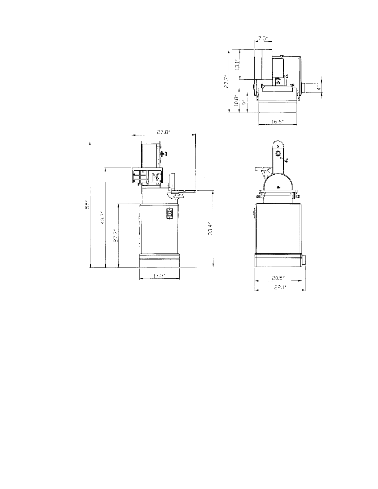
SPECIFICATIONS: Model 31A Sander
FIGURE 1
Disc size ..........................................................................................................................................................................12”
Disc speed........................................................................................................................................................... 2378 RPM
Sanding belt size .............................................................................................................................................. 6” W x 48” L
Upper & lower wheel ...........................................................................................................................4-3/8” Dia. x 6-1/4” L
Belt speed ...........................................................................................................................................2409 feet per minute
Motor ...................................................................................................... 1-1/2 HP, 1 Ph, 115/230V, 12/6 Amp, 1750 RPM
Belt position......................................................................................................................................0 , 45, and 90 degrees
Table size – disc......................................................................................................................................... 14-1/2” x 6-1/2”
Disc table tilt ................................................................................................................ 15 degrees up to 45 degrees down
Fence table tilt ...............................................................................................................0 degrees up to 45 degrees down
Fence size .................................................................................................................................................. 13” W x 7-1/2” L
Net weight ............................................................................................................................................................ 246.4 lbs.
NOTE: The above specifications were current at the time this manual was published, but because of our policy of
continuous improvement, Powermatic reserves the right to change specifications without notice and without incurring
obligations.
7
Page 8
RECEIVING
Remove the sander and base and any loose parts from
their containers. Check for damage and ensure all parts
are intact. Any damage should be reported to your
distributor and shipping agent immediately upon
discovery. Before proceeding with assembly, read the
manual thoroughly; familiarize yourself with correct
assembly and maintenance procedures and proper
safety precautions.
Contents of crate:
1 base assembly with motor
1 sander body
1 abrasive belt
1 abrasive disc
1 fence assembly
1 hardware bag
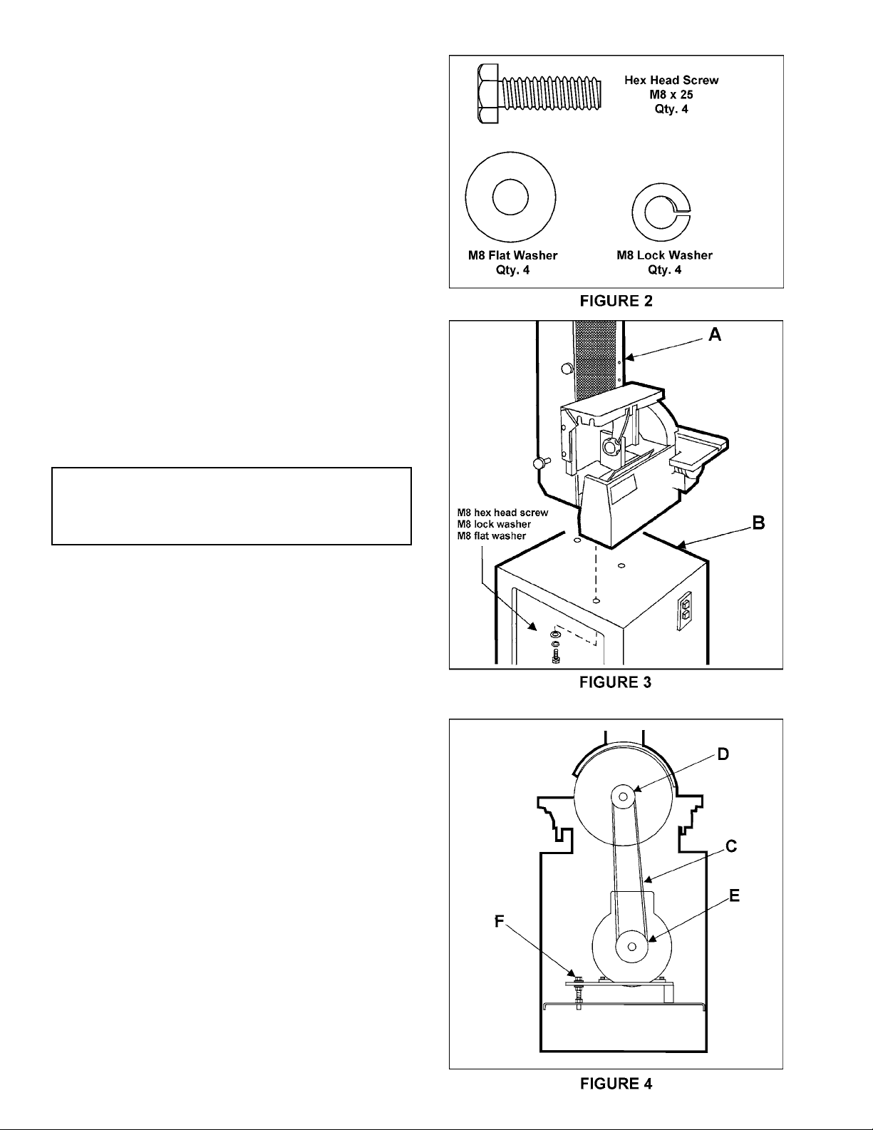
The contents of the hardware bag are drawn in Figure 2.
INSTALLATION & ASSEMBLY
Tools required
adjustable wrench (or socket wrench set)
hex wrenches
1. If the machine is to be secured to the floor, use
high quality lag screws through the four holes inside the
bottom of the base. If using a mobile base, be sure to
lock the wheels before assembling, operating or making
adjustments to the sander. (A mobile base for your
sander is available from Powermatic – stock # 708221.)
2. Mount the sander body (A) to the stand (B) with
four M8 x 25 hex head screws, four M8 lock washers
and four M8 flat washers as shown in Figure 3.
3. The drive belt (C) is already mounted on the drive
sheave (D) behind the disc, as shown in Figure 4.
However, it should be checked to ensure that it is in the
sheave groove.
4. Position the belt (C) around the motor sheave (E)
and tension the belt by adjusting the nuts (F) on the
tensioning screw.
NOTE: Proper tension is achieved when there is
moderate deflection in the belt midway between the two
sheaves.
ELECTRICAL CONNECTIONS
Wire the sander in accordance with the requirements of
the National Electrical Code (ANSI/NFPA70). See wiring
diagram on pages 20-21. Make sure your power source
matches the rating on the machine’s motor nameplate.
8
Page 9

WARNING: Electrical wiring should be done
!
by a qualified electrician. The machine must
be properly grounded to help avoid electrical shock
and associated hazards including possible death.
ADJUSTMENTS
Before putting power to the sander, inspect the machine
thoroughly. Check to ensure that all screws are tight, all
mechanical functions work freely, belt runs freely and
tracks properly, and the disc runs freely and does not
come into contact with the guard or table.
Turn the motor on and check for proper rotation direction
of the belts. The sanding belt should move from the
idler pulley toward the drive pulley while the disc should
rotate counter-clockwise with the operator facing the
disc.
Run the sander without sanding for a short period to
ensure the belt tracks properly and the disc adhesive
sticks properly to the disc.
ABRASIVE BELT INSTALLATION
To install or replace an abrasive belt, proceed as follows
(Figures 5 and 6):
1. Loosen the knob (A) and swing the belt end guard
(B) out of position.
2. Remove the side guard (C) by loosening and
removing the two screws holding it. Release tension on
the belt by loosening the tension knob (E) at the back of
the belt arm. Loosen the tracking screw (F) on the side of
the belt arm and move the drum forward.
3. Slide the worn sanding belt off the idler and driving
drums and install a new belt.
4. Retighten the belt tension screw (E) and tracking
screw (F). Check the tracking manually to ensure the belt
tracks properly. Put the side guard (C) back on and
secure with the screws. Swing the end guard (B) back
into position and re-tighten the knob (A).
ABRASIVE BELT ALIGNMENT
1. To properly align the abrasive belt, tighten the belt
tension screw (E) until the belt is relatively tight. See
Figure 5.
2. Manually rotate the belt with one hand while at the
same time adjusting the tracking screws with the other
hand until the belt is tracking in the center of the idler and
driving pulley. Caution is necessary since excessive
tension can stretch a belt to the point where it will not
track.
9
Page 10

3. Make final adjustments to the tracking by
momentarily starting and stopping the motor while at the
same time adjusting the tracking screw (F), Figure 5, at
the side of the belt arm. To lock the screw in place,
rotate the tracking screw locking nut (G) against the belt
arm.
PLATEN ADJUSTMENT
Due to wear, occasionally the platen may have to be
readjusted. To do this, proceed as follows:
Swing the end guard out of position and remove the side
guard. Loosen the two hex screws (A) on the opposite
side of the belt arm and adjust the platen. See Figure 7.
The platen should be 1/32” to 1/16” above the tangent
points of the pulleys and in contact with the belt at both
ends. A straight edge can be used with the belt to align
the platen.
SANDING TABLE ADJUSTMENT
The sanding table may be adjusted from any angle from
15 degrees up to 45 degrees down. To adjust, loosen the
lock wheels (A) on both sides and pivot table to the
desired angle as shown on the trunnion scale (B). Retighten the lock wheel (A). See Figure 8.
A 45-degree stop (C) is located under the table. Check
the angle of the table against the stop to make sure it is
45 degrees. If it is not, adjust by loosening the hex nut
and screwing the stop in or out as needed. Re-tighten
hex nut.
A zero-degree stop (D) is located behind the disc. See
Figure 9. The block should be set for quick placement of
the table to the 0 position (90 degree table). The block
must be swung out of position for the table to be tilted
downward. If major adjustment of the zero-degree stop is
necessary, loosen the socket head cap screws (E) to
raise or lower the bracket. For fine adjustment, loosen
the hex nut (F) and turn the screw in or out as needed.
Re-tighten hex nut (F).
Periodically check zero position on the table by using a
combination square. The angle between the table and
disk should be 90 degrees when the trunnion pointer is at
zero
WORK STOP
Your sander is equipped with a work stop for use with the
belt arm in the horizontal position (see Figure 17). When
installed, the work stop will prevent a work piece from
being thrown from the belt. If removed for throughsanding, the work stop should be immediately reinstalled
after the through-sanding operation (unless the fence
attachment is used in its place for 45-degree or vertical
10
Page 11

positions of the arm). Use a 10mm hex wrench to
remove or install the work stop.
BELT ARM POSITIONING
Your sander is equipped with a shot pin arrangement to
lock the belt arm in 0-degree, 45-degree, and 90 degree
positions. To position the belt, loosen the locking handle
(A) shown in Figure 10. Pull out on the shot pin (B),
shown in Figure 11, and swing the belt arm into the
desired position. Then release the shot pin. Check that
the pin has gone into position by attempting to move belt
arm back and forth. Re-tighten locking handle (A-Figure
10). When positioning the arm at any non-standard
angle, make sure the locking handle is tightened
securely.
NOTE: If the locking handle conflicts with the motion of
the belt arm, pull up on the handle and turn it out of the
way, as shown in Figure 10.
CHANGING MOTOR VOLTAGE
WARNING: ELECTRICAL WIRING SHOULD
!
BE DONE BY A QUALIFIED ELECTRICIAN. THE
MACHINE MUST BE PROPERLY GROUNDED TO
HELP AVOID ELECTRICAL SHOCK AND
ASSOCIATED HAZARDS INCLUDING POSSIBLE
DEATH.
To change the motor voltage, remove the terminal box
cover and rewire per the circuit shown on the cover. On
magnetic starter models, starter wiring and transformer
wiring (when used) will also have to be changed as
shown on the decals attached.
OPERATING THE SANDER
The belt and disc sander can be equipped with a variety
of abrasives and grit sizes to handle a wide variety of
materials, from soft woods to hardened steel. It can be
used to rapidly remove material and produce a mirror
finish. Using various types of fixtures, they can be used
to sand template forms, angles, freehand contours, and
flats on edges, surfaces and ends.
TEMPLATE FORMS
A template similar to that shown in Figure 12, can be
made to faciliate sanding multiple pieces to the same
size.
11
Page 12

FENCE/TABLE
The fence attachment is used with the belt sander and
can be positioned alternately as a table (with the belt arm
in upright position) or as a fence (with the belt arm in
horizontal position). The fence attachment surface has a
slot for a mitre gauge when the attachment is used as a
table. The fence attachment can be tilted between 90degree and 45-degree angles by loosening the knob (A)
on the center portion of the attachment. Manually move
the fence to the desired angle and tighten the knob (A).
See Figure 13.
To position the fence at an angle across the belt (for
skew sanding as shown in Figure 14), use a 3/16 hex
wrench to loosen the two socket head screws (B, Fig.
13). Rotate the fence attachment by sliding it around the
bolts using the curved slot (C). When the desired
position is reached, re-tighten the screws (B).
To change the fence attachment from fence to table, or
vice-versa, remove the two socket head screws (B)
shown in Figure 13. Remove the fence attachment and
rotate the pivot plate (D) 180 degrees lining the holes up
with the holes in the sander. See Figure 15. Place the
fence attachment on the pivot plate with the table
perpendicular to the belt. Line up the slots with the holes
on the pivot plate and the sander, then replace and
tighten the screws (B).
CAUTION: Always mount the base of the fence
!
attachment through the pivot plate. Failure to
do so could lead to damage to the fence attachment
and also ruin the sanding belt.
The chart on page 13 lists the various grits and materials
used and lists the grit symbols. It is generally better to
start with a slightly coarser abrasive than would seem
practical because it will give faster material removal,
generate less heat, and will sand more freely. As it dulls,
it will tend to act like a finer abrasive.
Too often, the user will expect one belt or disc to take
care of all situations; however, the materials to be
sanded, the desired finish and the amount of material to
be removed all have an effect on the selection grade of
grit, abrasive material and construction. Contact
suppliers of abrasive belts and discs for their
recommendations on the work to be done.
12
Page 13

TYPES OF OPERATIONS
Flat surface sanding is demonstrated in Figure 16,
where the major surface is sanded in a flat plane.
Edge sanding is a common type of long surface sanding
that can be done using the fence. See Figure 17.
Edge sanding and flat surface sanding can also be done
with the belt in a vertical position, by using the fence
assembly as a table.
Miters and compound miter cuts can be sanded using
the table and the optional miter gauge (available from
your Powermatic dealer). Special fixtures can also be
designed to use on the table for circular and form
sanding.
Contour sanding can be done using the idler pulley with
the end guard swung down. See figure 18.
CAUTION: Always swing the end guard
!
back in position and fasten it down
immediately after the completion of any operation
that required the guard to be moved out of position.
CAUTION: Keep in mind that abrasive sanding
!
develops heat, so burns can occur on wood if
you try to remove material too fast. With metal, it
may be necessary to have a container of water
nearby to keep the workpiece cool enough to hold it
by hand.
Flat surface and contour sanding can be done in the
horizontal, 45-degree, and vertical position of the belt
arm. To change position, pull out the shot pin and swing
arm to the desired position, then release shot pin (Figure
11).
MAINTENANCE
Make periodic or regular inspections to ensure that your
sander is properly adjusted, that all screws are tight, the
belts in good condition, that dust has not collected in the
motor or electrical enclosures and there are no loose or
worn electrical fittings or wiring.
LUBRICATION
All bearings used on the Model 31 Sander are sealed for
life and require no lubrication.
Monthly lubrication schedule:
The idler slide, Figure 19, and table trunnion (B-Fig. 8),
with good quality, non-hardening grease.
The table clamp screw (A-Fig. 8 on page 9) and belt arm
shot pin (B-Fig. 11 on page 10) with SAE No. 10 oil.
13
Page 14

GRIT COMPARISON CHART
Accessories
SANDING BELTS
57617110 6” x 48” Sanding Belt, 24 Grit, Closed Coat*
57617210 6” x 48” Sanding Belt, 40 Grit, Closed Coat
57617410 6” x 48” Sanding Belt, 60 Grit, Closed Coat
57617510 6” x 48” Sanding Belt, 80 Grit, Closed Coat
57617610 6” x 48” Sanding Belt, 100 Grit, Closed Coat
57617710 6” x 48” Sanding Belt, 120 Grit, Closed Coat
57512210 6” x 48” Sanding Belt, 150 Grit, Closed Coat
57512310 6” x 48” Sanding Belt, 180 Grit, Closed Coat
57432910 6” x 48” Sanding Belt, 24 Grit, Open Coat*
57422110 6” x 48” Sanding Belt, 40 Grit, Open Coat
57422210 6” x 48” Sanding Belt, 60 Grit, Open Coat
57422310 6” x 48” Sanding Belt, 80 Grit, Open Coat
57422410 6” x 48” Sanding Belt, 100 Grit, Open Coat
57422510 6” x 48” Sanding Belt, 120 Grit, Open Coat
57422610 6” x 48” Sanding Belt, 150 Grit, Open Coat
57422710 6” x 48” Sanding Belt, 180 Grit, Open Coat
14
SANDING DISCS
57698525 12” Sanding Disc, 36 Grit
57698650 12” Sanding Disc, 50 Grit
57698750 12” Sanding Disc, 60 Grit
57698850 12” Sanding Disc, 80 Grit
57698950 12” Sanding Disc, 100 Grit
57699050 12” Sanding Disc, 120 Grit
*NOTE:
Open coat - 70% grain coverage,
for woodworking applications.
Closed coat - 100% grain coverage
for metalworking and some
woodworking applications
Page 15

TROUBLE SHOOTING for Model 31A Sander
Problem Cause Solution
Machine fails to start. 1. Faulty switch. 1. Replace switch.
2. Bad motor. 2. Replace motor.
3. Not connected to power source. 3. Check connection.
4. Connected to wrong voltage. 4. Reconnect to correct voltage.
Belt won’t track. 1. Platen shifted or worn. 1. Raise platen to1/32” beyond the apex of the
drum.
2. Drum is worn. 2. Replace drum.
3. Belt is streched unevenly. 3. Replace belt.
Abrasive disc comes free 1. Improperly bonded. 1. Clean adhesive off aluminum and
of aluminum discs. reapply adhesive.
Belt slips or stalls on 1. Abrasive belt tension inadequate. 1. Tighten belt.
application of pressure. 2. Reduce pressure.
3. Tighten motor belt.
Disc stalls. 1. Motor belt loose. 1. Tighten motor belt.
2. Disc shaft key missing. 2. Replace pin.
Excessive abrasive belt 1. Too much pressure. 1. Reduce pressure.
replacement. 2. Not using full width of belt. 2. Stroke across belt using full width.
Belt arm won’t index. 1. Shot pin stuck. 1. Remove arm and free shot pin.
2. Broken spring. 2. Remove arm and replace spring.
15
Page 16

PARTS LIST: Body Assembly (Model 31A Sander)
No. Part No. Description Quantity
1 31A-1 Cast Base ........................................................................................................... 1
2 31A-2 Dust Chute (Disc) ............................................................................................... 1
3 31A-3 Sanding Disc ...................................................................................................... 1
4 31A-4 Disc Table........................................................................................................... 1
5 31A-5 Trunnion.............................................................................................................. 2
6 31A-6 90
7 31A-7 Trunnion Holder .................................................................................................. 2
8 31A-8 Set Screw, M10 x 55 .......................................................................................... 2
9 31A-9 Lock Knob, M10 x 57.......................................................................................... 1
10 31A-10 Ring Spanner...................................................................................................... 2
11 31A-11 Sanding Belt Guard ............................................................................................ 1
12 31A-12 Idler Bearing Housing ......................................................................................... 1
13 31A-13 Shaft ................................................................................................................... 1
14 31A-14 Key, 6 x 6 x 25 .................................................................................................... 2
15 31A-15 Bearing, 6204ZZ ................................................................................................. 2
16 31A-16 Aluminum Drum .................................................................................................. 2
17 31A-17 Hex Nut, M16 x 2 (L.H. Threads) ....................................................................... 1
18 31A-18 Knob ................................................................................................................... 1
19 31A-19 Index Pin.............................................................................................................1
20 31A-20 Knob, M6 x 12 .................................................................................................... 3
21 31A-21 Pan Head Screw w/ Flange, M6 x 12 ................................................................. 3
22 31A-22 Locking Handle, M10 x 1.25P ............................................................................ 1
23 31A-23 Lock Handle, M10 x 45....................................................................................... 1
24 31A-24 Side Plate Casting .............................................................................................. 1
25 31A-25 Rocker Arm......................................................................................................... 1
26 31A-26 Hex Head Bolt .................................................................................................... 1
27 31A-27 Platen.................................................................................................................. 1
28 31A-28 Side Cover.......................................................................................................... 1
29 31A-29 Bearing 6205ZZ .................................................................................................. 2
30 31A-30 Pan Head Screw w/ Flange, M5 x 8 ................................................................... 1
31 31A-31 Bearing Housing ................................................................................................. 1
32 TS-1551061 Lock Washer, M8................................................................................................ 3
33 TS-1504051 Socket Head Cap Screw, M8 x 25 ..................................................................... 3
34 31A-32 Key, 6 x 6 x 40 .................................................................................................... 1
35 31A-33 Shaft ................................................................................................................... 1
36 31A-34 Special Washer .................................................................................................. 2
37 31A-35 Pulley .................................................................................................................. 1
38 31A-36 Belt Guard........................................................................................................... 1
39 31A-37 Guard.................................................................................................................. 1
40 TS-1550041 Flat Washer, M6 x 16 ......................................................................................... 2
41 TS-1551041 Lock Washer, M6................................................................................................ 2
42 31A-38 Hex Head Bolt, M6 x 12...................................................................................... 2
43 31A-39 Hex Head Bolt, M6 x 20...................................................................................... 2
44 TS-1551041 Lock Washer, M6................................................................................................ 2
45 31A-40 Work Rest ........................................................................................................... 1
46 31A-41 Pivot Plate...........................................................................................................1
47 31A-42 Fence Table........................................................................................................ 1
48 31A-43 Fence End Bracket ............................................................................................. 2
49 31A-44 Fence Base ........................................................................................................ 1
50 31A-45 Long Link ............................................................................................................ 1
51 31A-46 Short Link............................................................................................................1
52 31A-47 Socket Head Button Screw, M6 x 12.................................................................. 4
53 31A-48 Hex Head Bolt .................................................................................................... 3
54 31A-49 Set Screw, M8 x 35 ............................................................................................ 1
55 TS-1540061 Hex Nut, M8........................................................................................................ 2
56 31A-50 Spring Pin, 6mm dia x 20 .................................................................................. 1
0
Stop Bracket................................................................................................. 1
16
Page 17

No. Part No. Description Quantity
57 31A-51 Set Screw, M6 x 8............................................................................................... 1
58 31A-52 Lock Washer, M16.............................................................................................. 2
59 31A-53 Hex Head Flange Bolt, M6 x 20.......................................................................... 4
60 31A-54 Lock Washer, M6................................................................................................ 2
61 31A-55 Hex Head Bolt, M6 x 8........................................................................................ 2
62 TS-1504041 Socket Head Cap Screw, M8 x 20...................................................................... 2
63 TS-1551051 Lock Washer, 8mm............................................................................................. 2
64 31A-56 Hex Nut, M16 x 2 (L.H. Threads)........................................................................ 1
65 31A-57 Socket Head Flat Screw, M6 x 16 ...................................................................... 1
66 31A-58 Socket Head Flat Screw, M8 x 20 ...................................................................... 2
67 31A-59 Spring.................................................................................................................. 1
68 31A-60 Pin, 6mm dia x 16 ............................................................................................... 2
69 TS-1550071 Flat Washer, M10 x 20........................................................................................ 2
70 TS-1505031 Socket Head Cap Screw, M10 x 25.................................................................... 2
71 31A-61 Roll Pin, 6mm dia x 24........................................................................................ 2
72 31A-62 Roll Pin, 6mm dia x 45........................................................................................ 4
73 31A-63 V-belt, A50 ..........................................................................................................1
74 31A-64 Roll Pin, 5mm dia x 30....................................................................................... 1
75 31A-65 Stop Block........................................................................................................... 1
78 31A-68 Lock Knob, 8mm x 20 ......................................................................................... 1
79 31A-69 Flat Washer, M8 x 30 dia.................................................................................... 1
80 31A-70 Lock Knob, M10 x 1.25P..................................................................................... 1
81 31A-71 Tilting Scale ........................................................................................................ 1
82 31A-72 Rivet, 2mm dia. x 5 ............................................................................................. 1
83 31A-73 Pan Head Bolt, M6 x 8........................................................................................ 1
84 31A-74 Pointer................................................................................................................. 1
85 TS-1550041 Flat Washer, M6 x 13.......................................................................................... 1
86 TS-1550071 Flat Washer, M10 x 20 dia.................................................................................. 2
87 TS-1540041 Hex Nut, M6........................................................................................................ 1
88 TS-1523071 Socket Set Screw, M6 x 25 ................................................................................ 1
89 TS-1550031 Flat Washer, M5 .................................................................................................1
90 TS-1503051 Socket Head Cap Screw, M6 x 20...................................................................... 2
91 TS-1524051 Socket Set Screw, M8 x 20 ................................................................................ 1
92 31A-75 Hex Head Bolt, M6 x 25...................................................................................... 1
93 TS-1540041 Hex Nut, M6........................................................................................................ 1
94 31A-76 Pin ....................................................................................................................... 1
95 31A-77 Mitre Gauge Assembly ....................................................................................... 1
17
Page 18

Body Assembly (Model 31A Sander)
18
Page 19

PARTS LIST: Stand Assembly (Model 31A Sander)
No. Part No. Description Quantity
1 31A-78 Stand................................................................................................................... 1
2 31A-79 Dust Outlet.......................................................................................................... 1
3 31A-80 Motor Pulley........................................................................................................ 1
4 31A-81 Motor, 1.5 HP, 1 Ph, 115/230V, 12/6 A, 1750 RPM .......................................... 1
31A-103 Motor, 2 HP, 3 Ph, 230/460V.............................................................................. 1
5 31A-82 Door .................................................................................................................... 1
6 31A-83 Door Latch Assembly.......................................................................................... 1
7 31A-84 Motor Mounting Bracket ..................................................................................... 1
8 31A-85 Cord Plate........................................................................................................... 1
9 31A-86 Strain Relief ........................................................................................................3
10 TS-1533042 Pan Head Screw, M5 x 12.................................................................................. 2
11 31A-87 Switch Box ..........................................................................................................1
12 TS-1540031 Hex Nut, M5........................................................................................................ 2
13 31A-88 Star Washer (External), 5M ................................................................................ 2
14 31A-89 Switch Cover....................................................................................................... 1
15 TS-1550021 Flat Washer, M4 .................................................................................................4
16 TS-1551021 Lock Washer, M4................................................................................................ 4
17 31A-90 Pan Head Screw, M4 x 8 .................................................................................... 2
18 31A-91 Pan Head Screw, M5 x 8 .................................................................................... 2
19 31A-92 Hex Head Screw, M10 x 135.............................................................................. 1
20 31A-93 Self Tapping Screw, M3.5 x 38........................................................................... 2
21 31A-94 Switch, 1Ph ......................................................................................................... 1
31A-104 Switch, 3Ph......................................................................................................... 1
22 TS-1551061 Lock Washer, M8................................................................................................ 4
23 31A-95 Hex Head Screw, M8 x 25 .................................................................................. 8
25 TS-1551061 Lock Washer, M8................................................................................................ 4
26 TS-1550061 Flat Washer, M8 x 18........................................................................................ 12
27 TS-1540061 Hex Nut, M8........................................................................................................ 1
28 31A-97 Motor Cord, 1Ph ................................................................................................. 1
31A-105 Motor Cord, 3Ph ................................................................................................. 1
29 31A-98 Power Cord, 1Ph ................................................................................................ 1
31A-106 Power Cord, 3Ph ................................................................................................ 1
30 31A-99 Hex Nut, M10..................................................................................................... 1
31 31A-21 Pan Head Screw w/ Flange, M6 x 12 ................................................................. 4
32 TS-1523041 Socket Set Screw, M6 x 12 ................................................................................ 1
33 31A-100 Pan Head Screw, M4 x 5 .................................................................................... 2
34 31A-101 Spacer Washer ................................................................................................... 2
35 31A-99 Hex Nut, M10..................................................................................................... 2
36 TS-1550071 Flat Washer, M10 ............................................................................................... 2
37 31A-102 Warning Label - Model 31A Sander (not shown) ............................................... 1
19
Page 20

Stand Assembly (Model 31A Sander)
20
Page 21

ELECTRICAL SCHEMATIC (Model 31A Sander)
21
Page 22

ELECTRICAL SCHEMATIC (Model 31A Sander)
22
Page 23

ELECTRICAL SCHEMATIC (Model 31A Sander)
23
Page 24

ELECTRICAL SCHEMATIC (Model 31A Sander)
24
Page 25

25
Page 26

26
Page 27

To order parts or reach our service department, please call our toll-free number between 8:00 a.m. and 4:30 p.m.
(CST), Monday through Friday. Having the Model Number and Serial Number of your machine available when you
call will allow us to serve you quickly and accurately. Locating the stock number of the part(s) required from your
parts manual will also expedite your order.
Phone No.: (800) 274-6848
Fax No. (800) 274-6840
If you are calling from Canada, please call 800-238-4746
E-mail: powermatic@wmhtoolgroup.com
Website: www.powermatic.com
27
Page 28

07/02
WMH Tool Group
P.O. Box 1349
Auburn, WA 98071-1349
Phone:(800) 274-6848
Fax: (800) 274-6840
E-mail: powermatic@wmhtoolgroup.com
Website: www.powermatic.com
Powermatic ALL RIGHTS RESERVED
28
 Loading...