

Page 1
20" THICKNESS PLANER
Model 208
Instruction Manual & Parts List
M-0460217
(800) 274-6848
www .powermatic.com
Page 2

This manual has been prepared for the owner and operators of a Powermatic Model 208 Planer .
Its purpose, aside from machine operation, is to promote safety through the use of accepted
correct operating and maintenance procedures. Completely read the safety and maintenance
instructions before operating or servicing the machine. To obtain maximum life and efficiency
from your planer and to aid in using the machine safely, read this manual thoroughly and follow
all instructions carefully.
Warranty & Service
The WMH T ool Group warrants every product it sells. If one of our tools needs service or repair , one of our
Authorized Repair S tations located throughout the United S tates can give you quick service.
In most cases, any one of these WMH Tool Group Repair S tations can authorize warranty repair, assist you in
obtaining parts, or perform routine maintenance and major rep air on your JET , Powermatic, Performax, or
Wilton tools.
For the name of an Authorized Repair S tation in your area, please call 1-800-274-6848.
More Information
Remember, the WMH Tool Group is consistently adding new products to the line. For complete, up-to-date
product information, check with your local WMH T ool Group distributor .
WMH T ool Group W arranty
The WMH Tool Group makes every effort to assure that its products meet high quality and durability standards
and warrants to the original retail consumer/purchaser of our products that each product be free from defects in
materials and workmanship as follow: 1 YEAR LIMITED WARRANTY ON ALL PRODUCTS UNLESS SPECIFIED OTHERWISE. This Warranty does not apply to defects due directly or indirectly to misuse, abuse,
negligence or accidents, normal wear-and-tear, rep air or alterations outside our facilities, or to a lack of maintenance.
THE WMH TOOL GROUP LIMITS ALL IMPLIED W ARRANTIES TO THE PERIOD SPECIFIED ABOVE, FROM
THE DATE THE PRODUCT WAS PURCHASED A T RET AIL. EXCEPT AS ST A TED HEREIN, ANY IMPLIED
WARRANTIES OR MERCHANTIBILITY AND FITNESS ARE EXCLUDED. SOME ST A TES DO NOT
ALLOW LIMITATIONS ON HOW LONG THE IMPLIED WARRANTY LASTS, SO THE ABOVE LIMIT A TION MA Y
NOT APPL Y TO YOU. THE WMH T OOL GROUP SHALL IN NO EVENT BE LIABLE FOR DEA TH, INJURIES
TO PERSONS OR PROPERTY, OR FOR INCIDENT AL, CONTINGENT , SPECIAL, OR CONSEQUENTIAL
DAMAGES ARISING FROM THE USE OF OUR PRODUCTS. SOME ST A TES DO NOT ALLOW THE EXCLUSION OR LIMITA TION OF INCIDENT A L OR CONSEQUENTIAL DAMAGES, SO THE ABOVE LIMIT A TION OR
EXCLUSION MA Y NOT APPL Y T O YOU.
T o take advant age of this warranty , the product or part must be returned for examination, postage prep aid, to an
Authorized Repair S tation designated by our office. Proof of purchase date and an explanation of the complaint
must accompany the merchandise. If our inspection discloses a defect, we will either repair or replace the
product, or refund the purchase price if we cannot readily and quickly provide a repair or replacement, if you are
willing to accept a refund. We will return repaired product or replacement at WMH's expense, but if it is
determined there is no defect, or that the defect resulted from causes not within the scope of WMH's warranty ,
then the user must bear the cost of storing and returning the product. This warranty gives you specific legal
rights; you may also have other rights which vary from state to state.
The WMH Tool Group sells through distributors only . Members of the WMH Tool Group reserve the right to
effect at any time, without prior notice, those alterations to parts, fittings, and accessory equipment which they
may deem necessary for any reason whatsoever.
Page 3

TABLE OF CONTENTS
SAFETY
General Rules ................................................................................................................................. 4
Specific Rules ................................................................................................................................. 4
FEATURES & SPECIFICATIONS ......................................................................................................... 5
RECEIVING THE PLANER .................................................................................................................... 6
INSTALLATION & ASSEMBLY
Lifting Handles ................................................................................................................................6
Stand Assembly .............................................................................................................................. 6
Table Extension Rollers .................................................................................................................. 6
Motor, Motor Pulley & Belt .............................................................................................................. 6
ADJUSTMENTS
Table Roller Adjustment .................................................................................................................. 7
Adjusting Table Extension Rollers .................................................................................................. 8
Depth of Cut ................................................................................................................................... 8
Cutterhead Adjustment ................................................................................................................... 9
Knife Adjustment ............................................................................................................................ 9
Replacing & Resetting Knives ...................................................................................................... 10
Checking Working Table Parallel to Cutterhead ........................................................................... 10
Adusting Working Table Parallel to Cutterhead ............................................................................ 11
The Transmitting Rollers of Your Planer ...................................................................................... 11
Adusting Infeed & Outfeed Roller Spring Tension........................................................................ 11
Anti-Kickback Fingers ................................................................................................................... 12
Height of Infeed Roller, Chipbreaker, Pressure Bar & Outfeed Roller ......................................... 12
Feed Speed Control ..................................................................................................................... 13
Changing Accessories for Lowest Feed Speed ........................................................................... 13
Return Rollers ............................................................................................................................... 13
Dust Collector Hood ..................................................................................................................... 13
MAINTENANCE ................................................................................................................................... 14
Changing Gearbox Lubricant........................................................................................................ 14
PARTS LIST & EXPLODED VIEW
Base Assembly ............................................................................................................................. 15
Cutterhead Assembly .............................................................................................................. 16-17
Table Assembly ............................................................................................................................ 18
Column Assembly ......................................................................................................................... 19
Gearbox Assembly .................................................................................................................. 20-21
OPTIONAL ACCESSORIES ................................................................................................................ 22
Page 4

SAFETY : General Rules
scrap material and sawdust to mimimize the danger of slipping.
READ THE MANUAL: Always read the owner's
manual carefully before attempting to use the
machine. Know the limitations and hazards associated with its use.
INST ALLATION: If mounting machine to the floor ,
use high quality anchor bolts through the mounting holes on the base. If using a mobile base, be
sure to lock the wheels.
PROTECTION: Take every precaution to protect
yourself, others around you, and the machine itself, from improper use. Safety is a combination
of using common sense, knowing how to use the
machine, and being alert at all times when using
the machine.
EYES: Always wear approved safety goggles,
glasses, or a face shield when operating this machine. There are no exceptions to this rule.
DRESS CODE: Do not wear loose clothing, neckties, jewelry , or gloves that can get caught in moving parts. Confine long hair . Keep sleeves above
the elbow.
PLACEMENT: Place machine so that potential
kickback area is not in line with aisles, doorways,
wash stations, or other work areas.
POWER ON: On machines equipped with a
manual starter make sure the starter is in "OFF"
position before connecting power to machine.
CHECK DAMAGED PARTS: Check for alignment of moving parts, binding of moving parts,
breakage of parts, mounting, and any other condition that may affect the machine's operation. A
guard or other part that is damaged should be properly repaired or replaced.
TURN POWER OFF: Never leave machine running attended. Do not leave machine until it comes
to a complete stop.
IF YOU ARE NOT thoroughly familiar with the
operation of planers, obtain advice from your supervisor, instructor or other qualified person.
DRUGS, ALCOHOL, MEDICATION: Do not operate tool while under the influence of drugs, alcohol, or any medication.
WARNING: The dust generated by certain woods
and wood products can be dangerous to your
health. Always operate machinery in well ventilated areas and provide for proper dust removal.
Use wood dust collection systems whenever possible.
ELECTRICAL GROUNDING: Y our machine must
be electrically grounded. If a cord and plug are
used, make certain the grounding lug connects to
a suitable ground. Follow the grounding procedure
indicated by the National Electric Code. Keep
power tools in dry areas free from moisture.
GUARDS: Be sure machine guards are in place
and in good working order. Use them at all times
on operations where they can be used. If a guard
must be removed for any operation, make sure it
is replaced immediately following completion of
that operation.
POWER OFF: Make sure the machine is either
unplugged or electrically disconnected and locked
out when performing maintenance or service work.
HOUSEKEEPING: Before turning on machine, remove all extra equipment such as keys, wrenches,
scrap, stock, and cleaning rags from the machine.
Keep the area around machine clean and free of
SAFETY: Specific Rules
KEEP CUTTERHEAD SHARP and free of all rust
and pitch.
CHECK MA TERIAL for loose knots, nails and other
defects.
REMOVE SHAVINGS only with the power "off".
CHECK that the switch is in "off" position before
plugging in power cord.
BEFORE MOVING table upward or downward,
loosen locking knobs. After choosing proper position, tighten locking knobs.
BE SURE the knives of cutterhead are correct and
all hex screws are secured tightly before use.
4
Page 5
KEEP HANDS AWAY from the feed rolls and
cutterhead.
REMOVE adjusting tools and loose articles from
machine before operating.
DO NOT OPERA TE machine while the gear cover
is open.
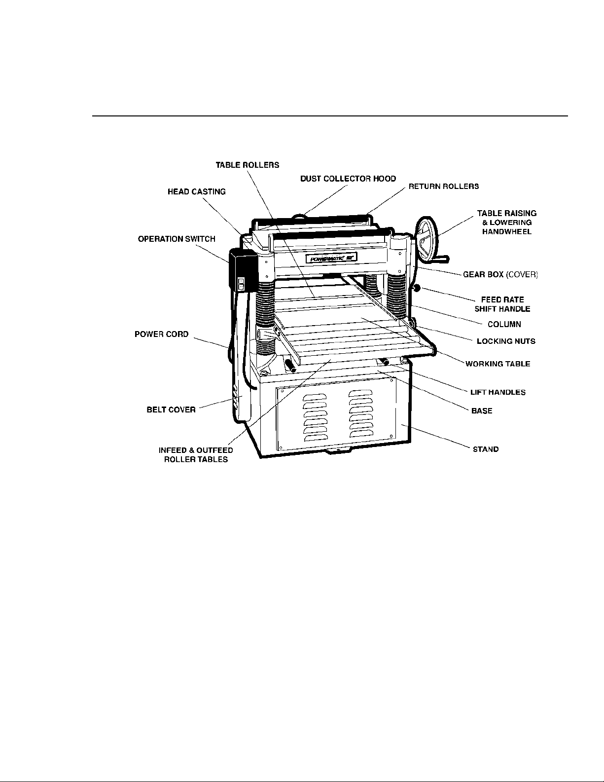
FEATURES & SPECIFICATIONS - Model 208, 20" planer
FIGURE 1
Table Area ................................................................................................ 25-3/4" x 20"
Maximum planing width ........................................................................................... 20"
Maximum planing thickness.......................................................................................8"
Full width cutting depth ......................................................................................... 3/32"
Minmum planing length........................................................................................6-3/4"
Knives ......................................................................................................................... 4
Blade size............................................................................................... 20" x 1" x 1/8"
Cutterhead speed ........................................................................................ 5,000 RPM
Cuts per minute.................................................................................................. 20,000
Cutterhead diameter ..........................................................................................3-3/16"
Feeding speed.......................................................................................... 24 & 31 FPM
Motor ................................................................................................. 3HP, 1Ph, 230V
5HP, 3Ph, 230/460V
Dust chute ...........................................................................................................5" dia.
Overall dimensions ........................................................ 26" L x 36-5/8" W x 41-3/8" H
Net weight ........................................................................................................ 640 lbs.
5
Page 6
RECEIVING THE PLANER
ST AND ASSEMBL Y
Carefully unpack the planer and any loose items
from the wood crate and inspect for damage. Any
damage should be reported to your distributor and
shipping agent immediately. Before proceeding
further, read your manual thoroughly to familiarize yourself with proper assembly, maintenance
and safety procedures.
Remove the screws that hold planer to the shipping crate. Remove the protective coating from
the table, bed rolls, feed rolls, cutterhead and loose
items packed with the machine, including lifting
handles and motor pulley. This coating may be
removed with a soft cloth moistened with Kerosene. DO NOT use acetone, gasoline or lacquer
thinner for this purpose. DO NOT use solvents on
plastic parts.
CAUTION: Use care when cleaning the
cutterhead as knives are very sharp.
INSTALLATION & ASSEMBLY
For best planing performance, locate planer on
solid, level foundation and anchor to the floor with
good quality lag screws:
1. With machine in position, test table surface lengthwise and crosswise with machinist
level. Place metal shims under low corners.
2. Check that all four corners are supported,
then tighten lag screws.
3. Re-test level of table surface in both directions, and adjust if necessary.
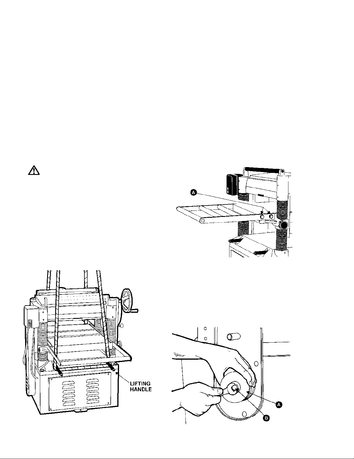
TABLE EXTENSION ROLLERS
Mount the table extension rollers to the table using the provided hex hd. screws (A) and washers,
Figure 3. The rollers should be adjusted before
using the planer, see "Adjusting Table Extension
Rollers" pg. 8.
LIFTING HANDLES
There are four lifting handles, Figure 2, furnished
with the machine. If any type of sling is used to lift
the machine, be sure to attach to lifting handles
only. Make sure machine is kept in level position
while lifting. The lifting handles can be pushed
back in when not in use.
FIGURE 3
MOTOR, MOTOR PULLEY & BELT
1. Assemble the motor pulley (A) to the motor shaft by aligning it with the key in the shaft,
and tighten the screw (B) in the motor shaft, as
shown in Figure 4.
FIGURE 2
6
FIGURE 4
Page 7
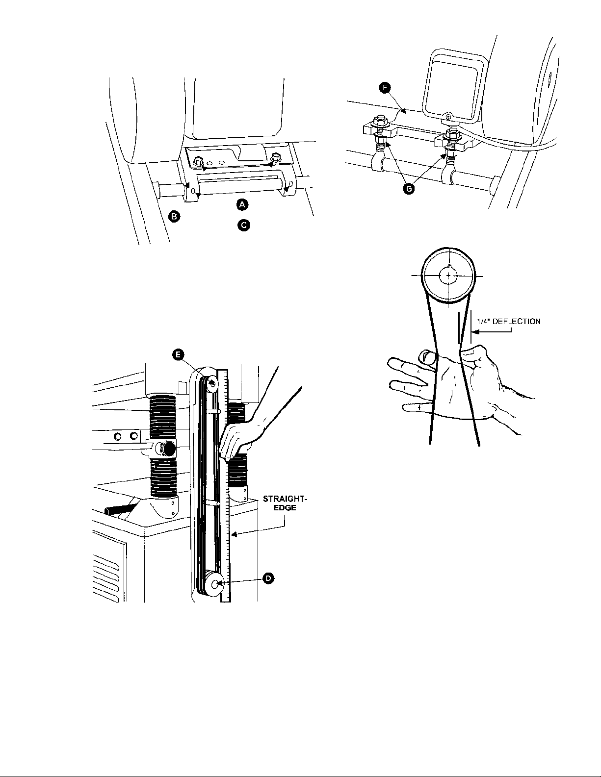
2. Assemble the motor to the motor mounting plate (B), using the provided hardware (A), Figure 5.
FIGURE 5
3. Using a straight edge, align the motor pulley (D) and cutterhead pulley (E) as shown Figure
6. The motor plate can be moved for alignment
by loosening the set screws (C) in the motor plate
(B) as shown in Figure 5.
FIGURE 7
FIGURE 6
4. Assemble the belts to the two pulleys, Figure 6. Adjust for the proper belt tension by raising
or lowering the motor plate (F), Figure 7, then
tighten the nuts (G). Proper tension is obtained
when there is approximately 1/4" deflection of the
center span of the pulleys by using light finger pressure, Figure 8.
FIGURE 8
ADJUSTMENTS
TABLE ROLLER ADJUSTMENT
Your planer is supplied with two table rollers (A),
Figure 9, which turn as the stock is fed into the
planer , thus reducing friction. It is not possible to
give exact dimensions on the proper height setting of the table rollers because each type of wood
behaves differently.
As a general rule, however, when planing rough
stock, the table rollers should be set at high position. When planing smooth stock the rollers should
be set at low position.
NOTE: When raising the roller higher above the
table, the range is from .003" to .006", see Figure
10.
7
Page 8
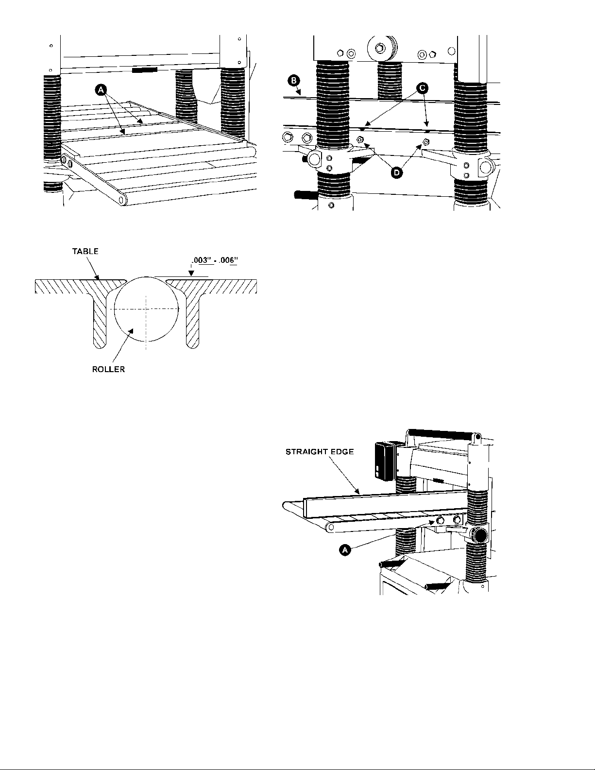
FIGURE 9
FIGURE 10
The table rollers are factory set for average planing and are parallel to the table surface. If you
desire to adjust the table rollers higher or lower,
proceed as follows:
1. Disconnect machine from power source.
2. Lay a straight edge (B), Figure 11, across
both rollers.
3. On one side of the table, loosen the screws
(C) with an Allen wrench, and turn the eccentric
shafts (D) to raise or lower the rollers.
4. When the proper height is achieved,
tighten screws (C).
5. Adjust the rollers from the opposite side
of the table in the same manner.
FIGURE 11
ADJUSTING TABLE EXTENSION
ROLLERS
Place a straight edge over the extension rollers
and the table, as shown in Figure 12, to make sure
the extension rollers and the table are at the same
height.
If necessary, adjust the table extension rollers as
follows:
1. Loosen the screws and washers (A) to
move the table extension roller to the proper position, then retighten the screws.
2. Adjust both front and rear extension rollers in the same manner.
IMPORTANT: Be sure that the height of front and
rear rollers are the same. The table rollers must
always be set parallel to the table.
8
FIGURE 12
ADJUSTING DEPTH OF CUT
The cutting depth scale is a combination inch/metric scale (A), Figure 13, with a cutting range from
0 to 8" (204mm). The distance of upward or downward movement is controlled by the handwheel
(B). One revolution is .059" (1.5mm). Before
Page 9
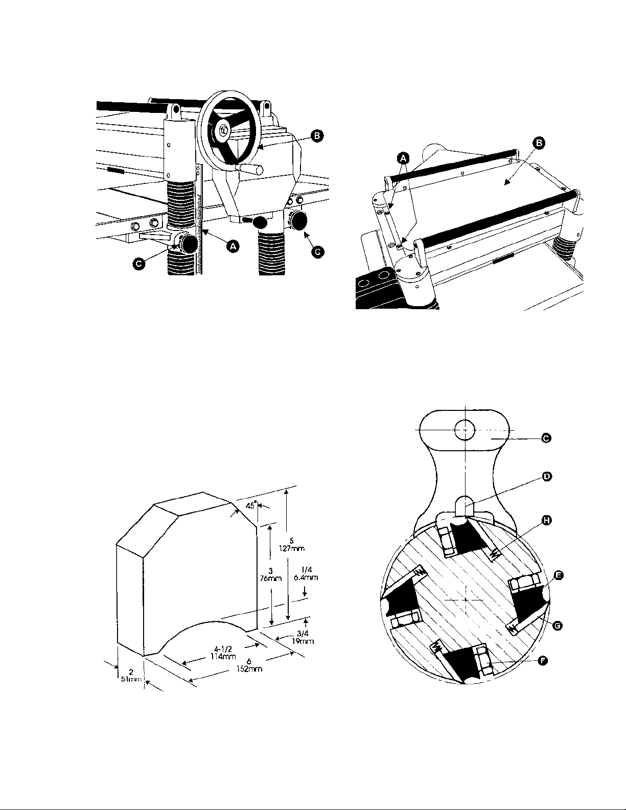
moving the table up or down, loosen the lock nuts
(C). After obtaining the proper table position,
tighten the lock nuts (C).
FIGURE 13
KNIFE ADJUSTMENT
When checking or adjusting the cutterhead knives,
proceed as follows:
1. Disconnect machine from power source.
2. Remove the six screws (A) and remove
upper cover (B), Figure 15.
CUTTERHEAD ADJUSTMENT
Although your planer was carefully adjusted at the
factory , it should be checked before being put into
operation. Any inaccuracies due to rough handling in transit can easily be corrected by following these directions.
To check the adjustments you will need a straight
edge, feeler gauge, and a home-made gauge
block made of hardwood. This gauge block can
be made by following the dimensions shown in
Figure 14.
FIGURE 15
3. To check and adjust knives, use the provided knife gauge (C) and check all four knives,
Figure 16. Knives should just contact the bottom
of the center protrusion (D) of the knife gauge.
FIGURE 14
FIGURE 16
4. If an adjustment to one or more of the
knives is necessary, slightly loosen the knife gib
(E), Figure 16, by turning the six locking screws
9
Page 10

(F) into the gib. Turn the screws just enough to
relieve stress in the cutterhead without disturbing
the setting of the knives. Do this for all four knives
at the same time.
5. With the gauge in place over a knife (G),
continue to loosen the locking screws (F) until the
lifter springs (H), begin raising the knife. When
knife comes into contact with the center protrusion (D) of the gauge, snug up the gib by lightly
backing out the six locking screws (F) against the
slot. NOTE: At this time, only tighten the knife
into the slot just enough to hold knife in position.
6. If additional knives must be reset, repeat
step 5.
7. After all four knives are set with screws
just snug, back out and tighten the six locking
screws (F), Figures 16 & 17, against the slot starting with the end screws first, then the center
screws, until the knife is securely held in the
cutterhead. Tighten remaining three knives in the
same manner.
IMPORTANT: Double check all screws for tightness.
same manner.
5. Thoroughly clean the knife slots, gibs,
springs and locking screws. Check the locking
screws; if the threads appear worn or stripped or
if the heads are becoming rounded, replace them.
6. Inspect the cutting edge of the knives for
nicks or wire edge. Hone the knives slightly using
a stone or if the knives are to be sharpened, maintain a cutting angle of 35 degrees as shown in
Figure 16.
7. Insert springs (H), knives (G) and gib (E)
into slot of cutterhead. Back out locking screws
(F) just enough to hold the knife in the cutterhead.
8. Place knife gauge (C) over knife as shown
in Figure 16.
9. While holding down on the knife gauge,
loosen all six locking screws (F) by turning them
into the gib (E) until cutting edge of knife comes
into contact with the protrusion (D) of the gauge.
Snug up the gib by slightly backing out the six locking screws against the slot.
NOTE: At this time, only tighten the knife into the
slot just enough to hold the knife in position.
10. Replace and reset the other three knives
in the same manner.
1 1. After all four knives are set with the screws
just snug, back out and tighten the six screws (F)
against the slot starting with the end screws first
and then the center screws until the knife is securely held in the cutterhead. Tighten the remaining three knives in the same manner.
FIGURE 17
REPLACING & RESETTING KNIVES
If the knives are removed for sharpening, care
must be exercised in replacing and resetting them.
Proceed as follows:
1. Disconnect machine from power source.
2. Remove six screws and upper cover (see
Figure 15).
3. To remove knife, loosen the gib (E), Figure 16, by turning the six locking screws (F) into
the gib. Remove gib (E), knife (G), and springs
(H). NOTE: The inner two springs will pop out
when the knife and gib are removed.
4. Remove the remaining three knives in the
10
WARNING: AFTER REPLACING AND
CHECKING KNIVES,
FULLY. MAKE CERTAIN THE DIRECTION OF
KNIVES IS CORRECT AND ALL 24 LOCKING
SCREWS ARE TIGHTENED SECURELY!
CHECK AGAIN CARE-
CHECKING WORKING T ABLE P ARALLEL
TO CUTTERHEAD
The working table is set parallel to the cutterhead
at the factory and no further adjustment should be
necessary . If your machine is planing a t aper, first
check to see if the knives are set properly in the
cutterhead. Then check to see if the working table
is set parallel to the cutterhead. Proceed as follows:
1. Disconnect machine from power source.
2. Place the gauge block (A), Figure 18, on
the working table directly under front edge of head
casting (B). Make slight contact by gently raising
table.
Page 11

FIGURE 18
ners.
NOTE: Turning sprocket clockwise will increase
the distance between the working table and
headcasting; counter-clockwise will decrease the
distance. This adjustment is very sensitive and it
should not be necessary to turn the sprocket more
than one or two teeth.
6. When adjustments are correct, replace
chain around corner sprocket, slide sprocket (C)
back to re-tension chain, tighten bolt (B) and replace and tighten bolt (A).
KNOW THE TRANSMITTING ROLLERS
OF YOUR PLANER
3. Move the gauge block to opposite end of
the working table. NOTE: Distance from the working table to edge of the head casting should be
the same.
4. Adjust opposite end in the same manner.
ADJUSTING WORKING T ABLE
P ARALLEL TO CUTTERHEAD
If the working table is not parallel to the cutterhead,
perform the adjustment procedures as follows:
1. Disconnect the machine from power
source.
2. Tilt planer on its side to expose underside
of base, as shown in Figure 19.
3. Remove bolt (A) and loosen bolt (B) which
will allow you to move the idler sprocket assembly
(C) far enough to release tension on the chain, as
shown in Figure 19.
A. Anti-Kickback Fingers
B. Infeed Roller
C. Chipbreaker
D. Cutterhead
E. Pressure Bar
F. Outfeed Roller
The infeed roller (B) and outfeed roller (F), Figure
20, are those parts of your planer that feed the
stock while it is being planed. The infeed roller
and the outfeed roller are under spring tension and
this tension must be sufficient to feed the stock
uniformly through the planer without slipping but
should not be so tight that it causes damage to
the board. The tension should be equal at both
ends of each roller.
FIGURE 19
4. Remove chain from the particular sprocket
on corner of base that must be adjusted.
5. Turn the sprocket by hand to bring that
corner into adjustment with the other three cor-
FIGURE 20
ADJUSTING INFEED & OUTFEED
ROLLER SPRING TENSION
To adjust the spring tension of the infeed and
outfeed rollers, turn screws (G & H) with an Allen
wrench, Figure 21. Turn screws on opposite end
of infeed/outfeed rollers in the same manner.
11
Page 12

FIGURE 21
ANTI-KICKBACK FINGERS
The anti-kickback fingers (A), Figure 20, are provided on your planer to prevent kickback of stock.
They operate by gravity and it is necessary to inspect them occasionally to make sure they are free
of gum and pitch, so that they move independently
and operate correctly.
To check and adjust the outfeed roller below the
cutting circle, proceed as follows:
1. Disconnect machine from power source.
2. Make sure the knives are adjusted properly as previously explained under "Checking &
Adjusting of Knives."
3. Place the gauge block (J) on the table directly underneath the cutterhead (D), Figure 23.
Using a 0.02" (0.5mm) feeler gauge (K) placed
on top of the gauge block, raise the working table
until the knife just touches the feeler gauge when
the knife is at its lowest point. Do not move the
working table any further until the outfeed roller is
adjusted.
HEIGHT OF INFEED ROLLER, CHIPBREAKER, PRESSURE BAR & OUTFEED
ROLLER
The infeed roller, chipbreaker, pressure bar and
outfeed roller are adjusted at the factory. The
infeed roller and the chipbreaker should be set at
0.004" (0.1mm) below the cutting circle; the pressure bar should be set at 0.008" (.02mm) below
the cutting circle; and the outfeed roller should be
set at 0.02" (0.5mm) below the cutting circle. See
Figure 22.
If an adjustment to the infeed roller, chipbreaker,
pressure bar or outfeed roller is necessary, use
the following steps as an example of procedure.
FIGURE 22
FIGURE 23
4. Move the gauge block (J) under one end
of the outfeed roller (F), Figure 24. The bottom of
the outfeed roller should just touch the top of the
gauge block. If an adjustment to the outfeed roller
is necessary , loosen the lock nut (L) and turn screw
(M) until the outfeed roller just touches the gauge
block. Then tighten lock nut (L).
5. Check and adjust opposite end of the
outfeed roller in the same manner.
12
Page 13

FIGURE 24
FEED SPEED CONTROL
Your machine is equipped with a spiral, serrated
infeed roller and a solid steel outfeed roller . When
the feed rollers are engaged, they turn to feed the
stock. The feed rollers slow automatically when
the machine is under heavy load for best planing
in all conditions. The feed rollers are driven by
chains (A), Figure 25, and the sprockets (B) which
take power directly from the cutterhead through
the oil bath gear box (C).
The gear box has two feed speeds. These are
set by pulling out or pushing in the shift lever (D)
while the machine is running. The feed speed
range is shown in Figure 26.
change the sprocket and the chain on your machine, proceed as follows:
1. Disconnect machine from power source.
2. Remove the three hex hd screws (E) and
washers, Figure 25.
3. Remove the three sprockets (B) from the
infeed roller, outfeed roller and the gear shaft at
the same time.
4. When sprockets (B) are removed, replace
the lower sprocket which will be assembled on the
gear shaft.
5. Assemble the three sprockets and chains
to the shafts, and tighten the hex hd. screws (E).
FPM
A/C
20/16 50P 12T
31/24 52P 18T
CHAIN
(F)
SPROCKET
(G)
FIGURE 25
CHANGING ACCESSORIES FOR
LOWEST FEED SPEED
The lowest feed speed for your planer (16.2 fpm
& 20.7 fpm) can be obtained by replacing the lower
(gear shaft) sprocket and the chain, Figure 26. To
FIGURE 26
RETURN ROLLERS
The two return rollers on the top of the machine
serve as a convenient rest for stock . They save
time and motion for the operator as the stock is
returned to the infeed side.
DUST COLLECTOR HOOD
The dust collector hood comes standard with the
model 208 planer , and helps maintain a clean and
safe work area. It is assembled to the planer with
hex head screws and washers.
13
Page 14

MAINTENANCE
Lubrication Guide for Model 208, 20" Planer
No. Position Interval Suitable Types of Oil Fig. No.
1 Chain Frequently Grease 29
Gear Box When operated more than 2,500 hours HD-100, Mobil Gear 627, Shell Omala 100,
2
3 Rollers Frequently SAE-30 30
4 Worm Gear Frequently Grease 31
5 Lead Screw Frequently Grease 31
6 Column Frequently Clean and SAE-30 31
7 Chain Frequently Grease 32
8 Bushing Frequently SAE-30 33
FIGURE 28
ESSO Spartan EP-100
29
FIGURE 29
FIGURE 31
CHANGING GEARBOX LUBRICANT
The lubricant in the gear box must be replaced
every 2,500 hours. Multi-purpose gear box lubricant will be suitable.
To replace the gearbox lubricant:
1. Remove the drain plug (A), Figure 29, and
filler cap (B). Drain dirty oil thoroughly.
2. Tighten the drain plug (A).
3. Fill with clean lubricant through hole (B).
4. Tighten filler cap (B).
14
FIGURE 30
FIGURE 32
FIGURE 33
Page 15

PARTS LIST: Base Assembly (208 Planer)
No. Part No. Description
1 6292793 Stand
2 6292794 Cover
3 6292795 Machine Screw, M6 X 1.0P-20
4 6292796 Bar
5 6292797 Motor Mount
6 6292711 Set Screw, M8 X 1.25P-8
7 6292798 Collar
8 6292799 Adjusting Bolt
9 6292651 Nut, M12 X 1.75P
10 6292683 Washer, 1/ 2
1 1 6292800 Hex Head Screw M8 X 1.25P-25
No. Part No. Description
12 6292801 Washer, 5/16
13 6292802 Nut, M8 X 1.25P
14 6292803 Motor, 3HP 1Ph
6292824 Motor, 5HP 3Ph
15 6292804 Key
16 6292805 Hex Head Screw, M12X1.75P-60
17 6292825 Power Supply Wire, 3 Ph
6292806 Power Supply Wire, 1 Ph
18 6292807 Relief Bushing
19 6292801 Washer, 5/16
15
Page 16

PARTS LIST: Cutterhead Assembly (208 Planer)
No. Part No. Description
1 6292617 Head Casting
2 6292618 Set Screw, M10 X 1.5P-12
3 6292619 Cutterhead
4 6292623 Hex Head Screw, M8 X 1.25P-10
5 6292621 Single Sided Knives (Set of 4)
6 6292622 Knife Locking Bar
7 6292620 Spring
9 6292625 Knife Setting Gauge
11 6292813 Cap Screw, M6 X 1.0P-10
12 6292628 Bearing 6206 ZZ
13 6292629 Key, 8 X 8 X 36
14 6292630 Machine Pulley
15 6292631 Washer, 8 X 30 X 3
16 6292632 Set Screw, M6 X 1.0P-25
17 6292633 Motor Pulley
18 6292634 Infeed Roller
19 6292635 Bushing
20 6292636 Spring
21 6292637 Screw, M22 X 1.5P-20
22 6292638 Plate
23 6292639 Hex Head Screw, M8 X 1.25P-20
24 6292640 Set Screw, M6 X 1.0P-16
25 6292641 Nut, M6 X 1.0P
26 6292642 Key, 5 X 5 X 23
27 6292643 Sprocket 31T
28 6292644 Washer, 6.2 X 22 X 3
29 6292645 Hex Head Screw, M6 X 1.0P-16
30 6292646 Outfeed Roller
31 6292647 Sprocket
32 6292648 Locking Bolt
33 6292649 Retaining Ring STW-12
34 6292650 Chip Breaker
35 6292651 Nut, M12 X 1.75P
36 6292652 Plate Spring
37 6292653 Washer, 1/4
38 6292654 Hex Head Screw, M6 X 1.0P-12
39 6292655 Shaft
40 6292656 Bracket
41 6292657 Pressure Plate
42 6292658 Spring Washer
43 6292659 Shaft
44 6292660 Set Screw, M6 X 1.0P-12
45 6292661 Set Screw, M6 X 1.0P-20
46 6292662 Plate Spring, 0.6
47 6292663 Chip Deflector Plate
48 6292664 Anti-kickback Finger
49 6292665 Collar
50 6292666 Shaft
51 6292667 Retaining Ring
52 6292668 Cut Limiter Plate
53 6292669 Flat Head Machine Screw,
M5 X 0.8P-12
54 6292670 Upper Cover
55 6292671 Gasket
56 6292672 Dust Hood
57 6292673 Roller Stand
No. Part No. Description
58 6292674 Roller
59 6292675 Cap Screw, M6 X 1.0P-16
60 6292678 Gear Box Worm
61 6292677 Cap Screw, M6 X 1.0P-50
62 6292676 Worm
63 6292679 Bearing 6201 Z
64 6292680 Retaining Ring, RTW-32
65 6292681 Key 4 x 4 x 10
66 6292682 Handwheel
67 6292683 Washer, 1/2
68 6292684 Handle
69 6292685 Scale
70 6292686 Machine Screw, M5 X 0.8P X 10
71 6292687 Cut Limit Pointer
72 6292814 Flat Washer
73 6292689 Cover
74 6292690 Spring Pin
75 6292691 Safety Hatch
77 6292693 Safety Hatch
78 6292694 Cap Screw, M8 X 1.25P-40
79 6292695 Pulley Guard
80 6292696 Bolt
81 6292815 Hex Head Screw, M6X1.0P-16
82 6292698 Nut, 5/16-18NC
83 6292699 Belt
84 6292700 Pulley Cover
85 6292710 Knob, 5/16-18NC
86 6292701 Switch Board
87 6816292 Switch, 3 HP, 1 PH
6816295 Switch, 5 HP, 3 PH
6816296 Switch, 5 HP, 3 Ph, 460V
88 6292703 Nut, M5 X 0.8P
89 6292704 Name Plate
90 6292705 Rivet
91 6292706 Chain 06B
92 6292707 Relief Bushing
93 6292708 Power Supply Wire, 1 Ph
6292826 Power Supply Wire, 3 Ph
94 6292709 Tooth Washer, EOW-5
95 6292813 Cap Screw, M6 X 1.0P-10
96 6292711 Cap Screw, M8 X 1.25P-8
97 6292816 Label
98 6292713 Collar
99 6292714 Shaft
100 6292715 Idle Pulley
101 6292716 Bracket
102 6292717 Shaft
103 6292718 Hanger
104 6292719 Spring
105 6292720 Collar
106 6292817 Round Head Screw, M6X1.0P-12
107 6292818 Hex Head Screw, M8X1.25P-18
108 6292819 Label
109 6292820 Label
1 1 0 6292821 Cap Screw, M5X0.8P-10
16
Page 17

EXPLODED VIEW: Cutterhead Assembly (208 Planer)
17
Page 18

PARTS LIST: Table Assembly (208 Planer)
No. Part No. Description
1 6292721 Middle Table
2 6292722 Roll
3 6292679 Bearing 6201 Z
4 6292724 Eccentric Shaft
5 6292660 Set Screw, M6 X 1.0P-12
6 6292725 Lock Bar
7 6292726 Locking Bolt
8 6292727 Locksmith
9 6292728 Knob
10 6292729 Cap Screw M8 X 1.25P-20
No. Part No. Description
11 6292730 Roller Frame
12 6292731 Roller
13 6292732 Hex Head Screw, M10 X 1.5P-25
14 6292626 Washer, 3/ 8
15 6292808 Shaft
16 6292809 Bushing
17 6292811 Washer
18 6292810 Hex Head Screw, M6X1.0P-12
18
Page 19

PARTS LIST: Table Base Assembly (208 Planer)
NO. PART NO. DESCRIPTION
1 6292733 BASE
2 6292618 SCREW, SET M10 X 1.5P-12
3 6292734 COLUMN
4 6292735 COLUMN
5 6292736 SCREW, LEAD
6 6292737 SCREW, LEAD
7 6292738 NUT
8 6292739 BUSHING
9 6292740 RING, RETAINING RTW-38
10 6292741 KEY 4 X 4 X 10
11 6292742 GEAR , 24T
12 6292649 RING, RETAINING STW-12
13 6285855 BEARING 6202 ZZ
14 6292744 RING, RETAINING RTW-35
16 6292746 SPROCKET 10T
NO. P ART NO. DESCRIPTION
17 6292626 WASHER, 3/8 X 20 X 2
18 6292627 NUT, M10 X 1.25P
19 6292747 WASHER 8.2 X 22 X 3
20 6292748 SCREW, HEX. HD. M18 X
1.25P-25
21 6292749 BRACKET
22 6292750 SHAFT
23 6292751 SPROCKET 10T
24 6292752 RING, RETAINING STW-15
25 6292753 CHAIN #40
26 6292754 POST, CRANE
27 6292755 RING, RETAINING ETW-19
28 6292756 BAND, PIPE
29 6292757 SCREW, MACHINE M5 X 0.8P-8
30 6292758 BEND, EXPANSION
19
Page 20

PARTS LIST: Gearbox Assembly (208 Planer)
NO. P ART NO. DESCRIPTION
1 6292759 Gear Box
2 6292760 Oil Seal
3 6292761 Bearing, 6204ZZ
4 6292762 Gear 16T
5 6292763 Cap Screw, M6 X 1.0P-20
6 6292764 Washer
7 6292675 Cap Screw, M6 X 1.0-16
8 6292765 Bearing 6201
9 6292766 Gear 47T
10 6292767 Shaft 18T
1 1 6292768 Key 5 X 5 X 12
12 6292769 Gear 71T
13 6292770 Key 5 X 5 X 10
14 6292771 Shaft 18T
17 6292772 Gear Assembly
19 6292813 Cap Screw, M6 X 1.0-10
20 6292774 Key 6 X 6 X 40
21 6292775 Ball, 6 Diameter
22 6292776 Spring
NO. P ART NO. DESCRIPTION
23 6292777 Shaft
24 6292778 Oil Seal SC25 X 47 X 6
25 6292791 Sprocket 18T
6292779 Sprocket 12T
27 6292792 Chain 06B X 52P
6292780 Chain 06B X 50P
28 6292654 Hex Head Screw, M6 X 1.0P-12
29 6292781 Clutch
30 6292782 Handle
31 6292653 Washer, 1/4
32 6292654 Hex Head Screw, M6 X 1.0P-12
33 6292783 Oil Ring P-12
34 6292784 Knob
35 6292785 Pin
36 6292786 Packing Piece
37 6292787 Cover
38 6292788 Cap Screw, M6 X 1.0P-25
39 6292789 Oil Plug, PT1/4-19
40 6292790 Cap Screw, M8 X 1.25P-50
20
Page 21

EXPLODED VIEW: Gear Box Assembly (208 Planer)
21
Page 22

Electrical Schematic: Model 208-1 (Single Phase)
22
Page 23

Electrical Schematic: Model 208-3 (Three Phase)
23
Page 24

OPTIONAL ACCESSORIES (208 Planer)
6292621 Knives (set of 4)
6292822 Low speed gear kit.
6292773 Hardware Kit.
24
Page 25

252627
Page 26

Page 27

T o order parts or reach our service dep artment, please call our toll-free number between 8:00 a.m. and 4:30 p.m.
(CST), Monday through Friday . Having the Model Number and Serial Number of your machine available when
you call will allow us to serve you quickly and accurately . Locating the EDP number of the part(s) required from
your parts manual will also expedite your order.
Phone No.: (800) 274-6848
Fax No. (800) 274-6840
If you are calling from Canada, please call 800-238-4746
E-mail: powermatic@powermatic.com
Website: www.powermatic.com
Page 28

04/01
P.O. Box 1349
Auburn, WA 98071-1349
Phone: (800) 274-6848
Fax: (800) 274-6840
E-mail: powermatic@powermatic.com
Website: www .powermatic.com
C
POWERMA TIC ALL RIGHTS RESERVED
 Loading...