

Page 1
This .pdf document is bookmarked
Operating Instructions and Parts Manual
22-inch Planer
Models 201 and 201HH
Powermatic
427 New Sanford Road
LaVergne, Tennessee 37086 Part No. M-0460224
Ph.: 800-274-6848 Revision J 02/2014
www.powermatic.com Copyright © 2014 Powerm atic
Page 2

Warranty and Service
Powermatic warrants every product it sells against manufacturers’ defects. If one of our tools needs service or repair,
please contact Technical Service by calling 1-800-274-6846, 8AM to 5PM CST, Monday through Friday.
Warranty Period
The general warranty lasts for the time period specified in the literature included with your product or on the official
Powermatic branded website.
• Powermatic products carry a limited warranty which varies in duration based upon the product. (See chart
below)
• Accessories carry a limited warranty of one year from the date of receipt.
• Consumable items are defined as expendable parts or accessories expected to become inoperable within a
reasonable amount of use and are covered by a 90 day limited warranty against manufacturer’s defects.
Who is Covered
This warranty covers only the initial purchaser of the product from the date of delivery.
What is Co vered
This warranty covers any defects in workmanship or materials subject to the limitations stated below. This warranty
does not cover failures due directly or indirectly to misuse, abuse, negligence or accidents, normal wear-and-tear,
improper repair, alterations or lack of maintenance.
Warranty Limitations
Woodworking products with a Five Year Warranty that are used for commercial or industrial purposes default to a
Two Year Warranty. Please contact Technical Service at 1-800-274-6846 for further clarification.
How to Get Technical Support
Please contact Technical Service by calling 1-800-274-6846. Please note that you will be asked to provid e pr o of
of initia l p u rch a s e whe n calling. If a product requires further inspection, the Technical Service representative will
explain and assist with any additional action needed. Powermatic has Authorized Service Centers located throughout
the United States. For the name of an Authorized Service Center in your area call 1-800-274-6846 or use the Service
Center Locator on the Powermatic website.
More Information
Powermatic is constantly adding new products. For complete, up-to-date product information, check with your local
distributor or visit the Powermatic website.
How S tate Law A pplies
This warranty gives you specific legal rights, subject to applicable state law.
Limitations on This Warranty
POWERMATIC LIMITS ALL IMPLIED WARRANTIES TO THE PERIOD OF THE LIMITED WARRANTY FOR EACH
PRODUCT. EXCEPT AS STATED HEREIN, ANY IMPLIED WARRANTIES OF MERCHANTABILITY AND FITNESS
FOR A PARTICULAR PURPOSE ARE EXCLUDED. SOME STATES DO NOT ALLOW LIMITATIONS ON HOW
LONG AN IMPLIED WARRANTY LASTS, SO THE ABOVE LIMITATION MAY NOT APPLY TO YOU.
POWERMATIC SHALL IN NO EVENT BE LIABLE FOR DEATH, INJURIES TO PERSONS OR PROPERTY, OR
FOR INCIDENTAL, CONTINGENT, SPECIAL, OR CONSEQUENTIAL DAMAGES ARISING FROM THE USE OF
OUR PRODUCTS. SOME STATES DO NOT ALLOW THE EXCLUSION OR LIMITATION OF INCIDENTAL OR
CONSEQUENTIAL DAMAGES, SO THE ABOVE LIMITATION OR EXCLUSION MAY NOT APPLY TO YOU.
Powermatic sells through distributors only. The specifications listed in Powermatic printed materials and on the official
Powermatic website are given as general information and are not binding. Powermatic reserves the right to effect at
any time, without prior notice, those alterations to parts, fittings, and accessory equipment which they may deem
necessary for any reason whatsoever.
Product Listing with Warranty Period
90 Days – Parts; Consumable items
1 Year – Woodworking Machinery used for industrial or commercial purposes
5 Year – Woodworking Machinery
NOTE: Powermatic is a division of JPW Industries, Inc. References in this document to Powermatic also apply to
JPW Industries, Inc., or any of its successors in interest to the Powermatic brand.
2
Page 3

Table of Contents
Warranty and Servic e .............................................................................................................................. 2
Table of Contents .................................................................................................................................... 3
Warning ................................................................................................................................................... 4
Introduction ............................................................................................................................................. 6
Specifica tions ................................................................................................................ .......................... 6
Recei ving ................................................................................................................................................ 7
Installation ............................................................................................................................................... 7
Installing Dust Hood ............................................................................................................................. 8
Grounding Inst r uc tions ............................................................................................................................. 8
Inspection ................................................................................................................................................ 9
Adjustments ................................................................................................................... ......................... 9
Depth of Cut......................................................................................................................................... 9
Feed Rate Adjustment ......................................................................................................................... 9
Belt Tension ......................................................................................................................................... 9
Opening Hood .................................................................................................................................... 10
Knife Installation and Adjustment (Straight Cutterhead only) .............................................................. 10
Replacing or Rotating Knife Inserts (Heli c al Cutt er head only) ............................................................. 11
The Planer’s Feed System ..................................................................................................................... 12
Anti-Kickback Fingers ........................................................................................................................ 12
Infeed Roller ...................................................................................................................................... 12
Chipbre aker ....................................................................................................................................... 13
Pressure Bar ...................................................................................................................................... 13
Outfeed Roll er .................................................................................................................................... 14
Table Roller s ...................................................................................................................................... 14
Table Adj ustments ............................................................................................................................. 15
Operating Controls ................................................................................................................................ 16
Test Cutting and T r oubleshooting .......................................................................................................... 16
Maintenance .......................................................................................................................................... 18
Lubrication ......................................................................................................................................... 18
Troubleshooting: Planer Operating Problems ......................................................................................... 19
Troubleshooting: Mechanical and Electrical Problems ............................................................................ 20
Replacement Parts ................................................................................................................................ 21
Parts List: Base Assembly .................................................................................................................. 22
Gearbox Assembly ............................................................................................................................. 24
Parts List: Gearbox Assembly ............................................................................................................ 25
Column Assembly .............................................................................................................................. 26
Parts List: Column Assembly .............................................................................................................. 27
Table Assembly ................................................................................................................................. 28
Parts Lis t: Ta b le Assembly ................................................................................................................. 29
Parts List: Top Cover Assembly ......................................................................................................... 30
Cutterhead Assembly ......................................................................................................................... 31
Parts List: Cutt er head A ssembly ........................................................................................................ 32
Electri c al Connec tions – 1 Phase, 230 Volt ............................................................................................ 34
Electri c al Connec tions – 3 Phase, 230 Volt ............................................................................................ 35
3
Page 4

Warning
1. Read and understand the ent ire owner’s manual befor e att em pting assembly or operation.
2. Read and understand the warnings po sted on the m achine and i n thi s manual. Fail ure to comply wit h
all of these warnings m ay cause seriou s i njury.
3. Replace the warning labels if they become obscured or removed.
4. This planer i s designed and intended f or use by properly trai ned and experienced personnel only. If
you are not familiar with the proper and safe operation of a planer, do not use until proper training and
knowledge have been obtained.
5. Do not use this planer for other than its intended use. If used for other purposes, Powermatic
disclaim s any real or i mplied warrant y and h olds itsel f harml ess from any injury t hat may r esult f rom
that use.
6. Al ways wear ap prov ed saf ety glasses/face shields whil e usi ng thi s planer. Ev er yday eyegl asses onl y
have impact resistant lenses; they are not safety glasses.
7. Before operating t his planer, remove tie, rings, watches and other jewelr y, and roll sleeves up past
the elbows. Remove all loose clothing and c onfine long hair. Non-sli p footwear or anti-skid floor strips
are recommended. Do not wear gloves.
8. Wear ear protector s (plugs or muffs) during ext ended peri ods of oper ation.
9. Some dust created by power sanding, sawing, grinding, drilling and other construction activities
contain chemi cals known to cause cancer , bir th defects or other r eproductiv e harm . Some exampl es
of these chemic als are:
Lead from lead based paint.
Crystalline silica from bricks, c em ent and ot her m asonry pr oducts.
Arsenic and chromium from chemically treated lumber.
Your risk of exposure varies, depending on how often you do this type of work. To reduce your
exposure to these chemicals, work in a well-ventilated area and work with approved safety
equipment, such as face or dust masks that are specifically designed to filter out microscopic
particles.
10. Do not operate this machi ne while tired or under the influence of drugs, alcohol or any medication.
11. M ak e c er tain the machine is properl y grounded.
12. W ith the exception of feed rate adjustm ent, make all machine adjustments or maint enance with the
machine disconnec ted from t he power source. A mac hine under repair should be RED T AGGED to
show it should not be used until the maintenance is complet e.
13. Remove adjusting keys and wrenches. Form a habit of checking to see that keys and adjusting
wrenches are removed from the machine before turning it on.
14. Keep safety guards in place at all times when the machi ne is in use. If removed for maintenance
purposes, use extreme caution and replace the guards immediately after c om pletion of maintenance.
15. Check damaged parts. Before further use of the machine, a guard or other part that is damaged
should be carefully checked to determine that it will operate properly and perform its intended
function. Chec k for alignment of moving par ts, binding of moving parts, breakage of parts, mounting
and any other condi ti ons that m ay affect its operati on. A guard or ot her part that i s damaged should
be properly repaired or replaced.
16. P r ov ide for adequate space surroundi ng work ar ea and non-glare, ov er head lighting.
17. K eep the floor around the machi ne cl ean and fr ee of scrap material, oil and grease.
18. K eep v isitors a safe distance fr om the work area. K eep chi ldren away.
4
Page 5

19. M ak e y our workshop child proof wit h padloc k s, m aster swit c hes or by r em ov ing starter keys.
20. Giv e your work undivi ded attention. Looki ng around, carryi ng on a conversati on and “horse-play” ar e
careless acts that can r esul t in serious injury.
21. M aintain a balanc ed stance at all t imes so that you d o not fall or lean against mov ing parts. Do not
overreach or use excessiv e force to perform any machine operation. Stand to the side out of li ne with
the table and make sure no one el se i s standi ng in line with the table.
22. Use the ri ght t ool at the cor rect speed and feed r ate. Do not for ce a tool or attachment to do a job for
which it was not designed. T he ri ght tool will do the job better and m or e safely.
23. Mai ntain t ools with care. Keep kniv es sharp and clean f or the best and saf est perf ormanc e. Dull tool s
increase noise lev els and can cause ki ckbacks and glazed surf aces. Broken gi bs/kniv es that are not
securely loc ked in the cutterhead c an be thrown out of the planer causing severe or fatal injury as
well as severe damage to the machine. Follow instructions for lubricating machine and changing
accessories. Use recommended accessories; improper accessories may be hazar dous.
24. Do not attempt to pl ane boards shorter than 10” (254mm) in length wit hout butting a board of equal
thickness behind i t to help it thr ough the planer . Be sure the last board of a butted sequence i s 10” or
longer.
25. Do not feed stacked boards through a planer; a kickback may occur causing severe or fatal injury.
26. Do not pl ane a board with l oose knots or with nail s or any foreign m aterial on its surface. Twisted,
warped, or wind- in stock should f irst be joint ed on one surface bef ore attempting to pl ane a parallel
surface on the planer . Serious stock flaws cannot be rem ov ed by use of a planer alone.
27. If the board bei ng planed stops feedi ng, disengage or t urn the f eed off and turn the power off . Wait
until the cutt erhead comes to a complete stop before lowering the t able to remove the board. Never
lower the tabl e with t he power on and the stoc k st ill in the machine, as a kickback can occur.
28. Keep hands outside of the machine. Never reach under the guards to try to clear stock that has
stopped feedi ng. When star ti ng a cut , do not hav e any part of the hand s under that par t of t he board
that is over the table; the infeed roller will engage the board and force it down against the table
causing a pinching action.
29. Disconnect machine from power source before cl eaning. Use a brush or compressed air to remov e
chips or debris — do not use your hands.
30. Do not stand on the machine. Seri ous i njury could occur if the machine tips over.
31. Never leave the mac hine r unning unattended. Turn the power off and do not leav e the m ac hine until it
comes to a complete stop.
32. Remove loose items and unnecessary work pieces from the area before starting the machine.
Familiariz e you rself with the following safety no tices used in this manual:
This means that if precautions are not heeded, it may result i n mi nor injury and/or
possible machine damage.
This means that if precautions are not heeded, it may result i n serious injury or possibly
even death.
- - SAVE THESE INSTRUCTIONS - -
5
Page 6

Introduction
This manual is provided by Powermati c covering the safe operat ion and maintenance pr ocedures for a
Powermatic Model 201 and 201HH Planer. This manual contains instructions on installation, safety
precautions, gener al oper ati ng procedur es, mai ntenance i nstructi ons and parts breakdo wn. Thi s mac hine
has been designed and con structed t o provide year s of troubl e free operation if used in accordanc e with
instructi ons set forth i n this manual . If there are any questions or comm ents, please contact either your
local supplier or Powermatic. Powermati c can also be reached at our web site: www.powermati c .com.
Specifications
Model Number ....................................................................... 201................................................... 201HH
Stock Number (7.5HP , 1Ph, 230V) ................................ 1791261.................................................1791267
Stock Number (7.5HP , 3Ph, 230V) ...............................................................................................1791268
Working Wid th (in.) .................................................................. 22.......................................................... 22
Maximum Depth of Cut (in.) .................................................. 3/16....................................................... 3/16
Minimu m Thicknes s (in.) ......................................................... 1/8......................................................... 1/8
Maximum Thickness (in.) ..................................................... 9-1/4...................................................... 9-1 /4
Segmented Infeed Roller Diameter (in.) ..................................... 3............................................................ 3
Steel Outfeed Roller Diameter (in.) ............................................ 3 ............................................................ 3
Feed Speeds (FPM) .................................................... 20 and 30............................................... 20 and 30
Bed Rollers, Front Adjustable .................................................... 2............................................................ 2
Minimum Lengt h Work piec e (i n.).............................................. 10.......................................................... 10
Cutterhead Style .............................................................. stra ight.................................................... helical
Cutterhead Diameter (in.) .................................................... 3 -1/4...................................................... 3-1/4
Number of Knives ...................................................................... 4............................. 125 four-sided inserts
Number of Cutterhead Rows................................................... n/a............................................................ 5
Cutterhead Speed (RP M ) .................................................... 4800...................................................... 4800
Cuts per Minute ................................................................ 19,200......................................... not applicable
Table Size (LxW)(in.) ................................................. 32-1/2 x 24............................................. 32- 1/2 x 24
Table Support ............................................................... 2-column................................................ 2-column
Manual Table Height Adjustment (in.) ...................... 1 turn = 1/16.......................................... 1 turn = 1/16
Readout Scale ................................................................... mm/ in..................................................... mm/in
Dust Port Diameter (in.) ............................................................. 5............................................................ 5
Dust Collecti on Minimum CFM Required ................................ 900........................................................ 900
Shipping Weight , approximate (lbs.)..................................... 1430...................................................... 1430
Net Weight, approximate (lbs.) ............................................. 1350...................................................... 1350
Overall Dimensions (LxWxH)(in.) .............................. 42 x 49 x 59........................................... 42 x 49 x 59
The above specifications were current at the tim e this manual was publi shed, but because of our policy of
continuous im provement, Powerm atic reserves the right t o change specific ations at any time and without
prior notic e, wit hout incurring obligati ons.
6
Page 7
Receiving
Open shipping crate and check for shipping
damage. Report any damage immediately to
your distributor. Read the instruction manual
thoroughly for assembly, maintenance and
safety instructions.
Contents of crate:
1 planer
1 dust chute w/ fasteners
4 screws w/ hex nuts (for leveling feet)
4 leveling feet
1 knife-setting gauge (201 only)
2 star point screwdriv er s (201HH only)
1 set of 10 knife inserts (201HH only)
10 knife insert screws (201HH only)
1 6mm hex wrench
1 8mm hex wrench
1 10mm hex wrench
1 12mm & 14mm wrench
1 22mm & 24mm wrench
1 Operating Instruct ions and Parts Manual
1 Warranty Card
Installati on
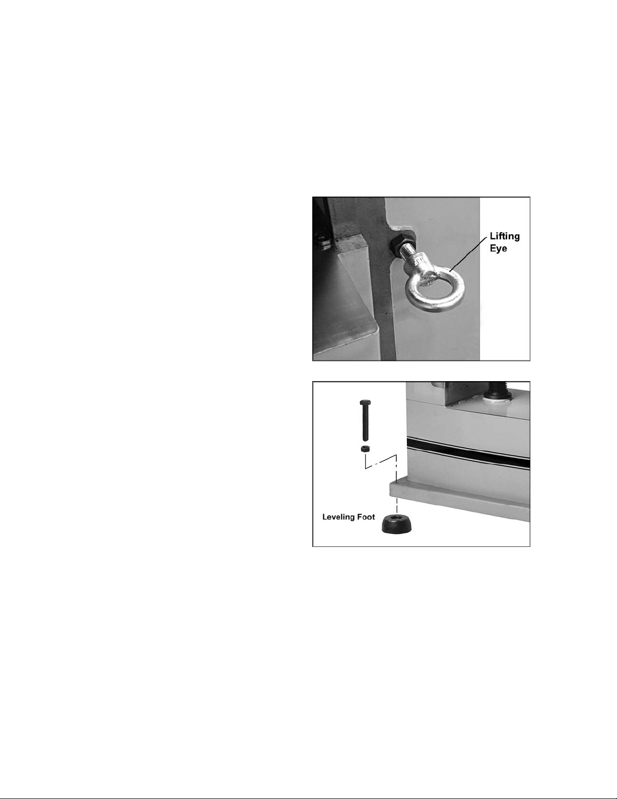
Remove the screws holding the base of the
machine to the ski d. Use the lif ting eyes on fr ont
and back of the pl aner f or hoisti ng it off the ski d.
See Figure 1. Make sure the hex nuts are
tightened bef ore lifting. The lifting eyes can be
removed once the planer is situated.
Place the planer on a solid foundation,
preferably a concrete floor. The four leveling feet
should be placed beneat h the corners, and the
screws and hex nuts used for leveling
adjustments. See Figure 2. Alternatively, you
can secure the mac hine t o the fl oor by usi ng l ag
screws through the holes in the base.
The machine area should be clean, dry, well
ventilated, and well lighted. Since planers can
create noise probl ems, the site selecti on should
be one which mi nim izes rev erberant sound f rom
walls, ceilings and other equipment. Electricals
should be installed so that they are protected
from damage and exposure.
Exposed metal parts have been given a
protectiv e coating at the fact ory. This should be
removed wit h a soft rag and k erosene or a good
commercial solvent. Do not use an abrasive
pad, as it may scratch polished metal surfaces.
Figure 1
Figure 2
IMPORTANT: All knives or knife inserts on
the cutterhead should be checked for
tightness before operating the planer.
7
Page 8

Installing Dust Hood
Mount the dust hood with t he eight M6 x 10mm
hex screws, eight spring washer s, and eight flat
washers. See Figure 3.
It is strongly recomm ended that a dust collection
system be connected to the 5” port on the
planer’s dust hood. The system should be of
sufficient volume for this size planer. If a dust
collection system is not used, the user is
cautioned against the health hazard and the
limitati ons in the OSHA regul ation for empl oyee
or student exposure t o dust par ticles.
Contact your deal er or visit waltermeier.com for
a line of availabl e dust c ollec tors.
Grounding Instructions
Electrical connections must
be made by a qualified electrician in
compliance with all relevant codes. This
machine must be properly grounded to help
prevent electrical shock and possible fatal
injury.
This mac hine m ust be grounded. I n the event of
a malfuncti on or break down, groundi ng prov i des
a path of least r esistance f or electric current to
reduce the ri sk of el ectri c shock .
Improper connection of the equipmentgrounding conductor can result in a risk of
electric shock. The conductor with insulation
having an outer surface that is green with or
without yellow stripes, is the equipmentgrounding conduct or . If r epair or replac em ent of
the electric cord or plug is necessary, do not
connect the equipment-groundi ng c onduc tor to a
live terminal.
Check with a qualified electrician or service
personnel if the grounding instructions are not
completely understood, or if in doubt as to
whether the tool is properly grounded.
Make sure the voltage of your power supply
matches the specif ications on the m otor plate of
the Planer. T he m achi ne shoul d be c onnec ted to
a dedicated cir c uit.
You may eit her install a pl ug or “hard-wire” the
Planer dir ectly t o a contr ol panel. If the Pl aner is
to be hard-wired to a panel, make sure a
disconnect is available for the operator. During
hard-wiring of the Planer, make sure the fuses
have been rem oved or the breakers have been
tripped i n the circuit t o whic h the machine will be
connected. Pl ace a warning placard on t he fuse
holder or circuit breaker to prevent it being
turned on while t he Pl aner is bei ng wir ed.
Figure 3
8
Page 9
Inspection
Before putt ing power to t he m achi ne, c heck that
all screws are tight, that all mec hanic al functions
work freel y and that the cutter head turns freel y
without knife contact with the chipbreaker or
pressure bar. On the helical cutterhead model,
check that all k nife inserts are properly torqued.
Adjustments
Tools required:
Philips screwdriver
Hex wrenches (provided)
Open-end wrench (provi ded)
Depth of Cut
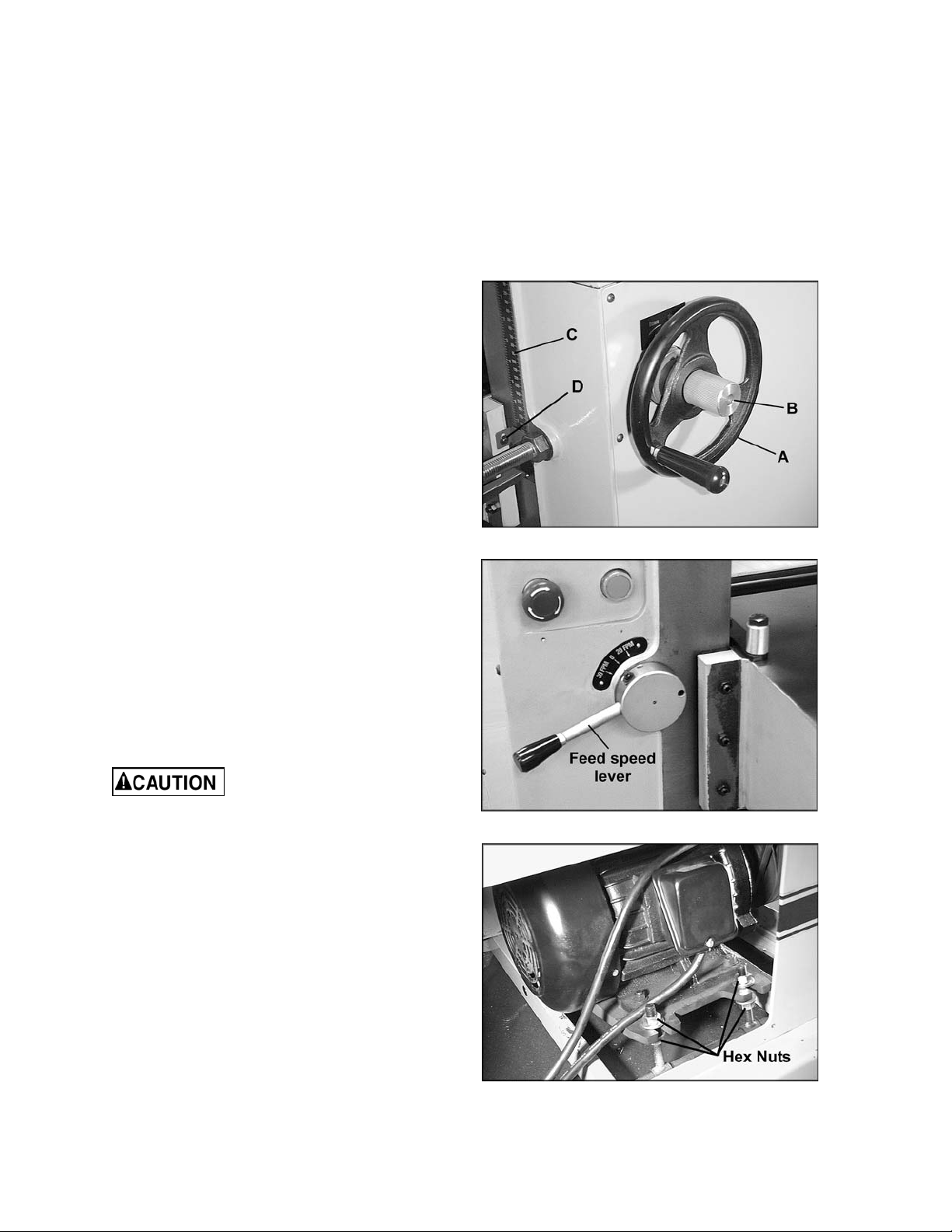
Depth of cut is controll ed by raising or l owering
the table. This is done by using the handwheel
(A), shown in Figure 4.
1. Loosen the lock knob (B , Fi gur e 4).
2. Raise or lower the table to the desired
position (c lockwise to raise). One revol ution
of the handwheel equals 1/16" . The distance
can be read on the scale (C, Fi gur e 4).
3. Retighten loc k knob (B, Fi gur e 4) .
Figure 4
4. The pointer (D, Figure 4) can be adjusted
slightly if the scale should ever need
recalibrating.
Feed Rate Adjustment
The Model 201 i s equi pped wit h select abl e f eed
speed roller s that feed stoc k at 20 and 30 feet
per minute. To adjust speed, turn l ever shown in
Figure 5, while the planer is r unning.
Alw ays change sp eeds whi le
the planer is running to avoid damage to the
gearbox.
Belt Tension
1. Disconnect machine from power source.
2. Remove lower rear cover of machine, and
use the hex nuts to adjust tension. See
Figure 6. A djust motor plate up or down until
correct belt tension is achieved. To lower
motor plate, loosen lower nuts and tighten
upper nuts. To raise motor plate, do the
opposite.
Figure 5
3. Correct tension is obtained when there is
approximately 1/4" deflection in the center
span of the belts using light finger pressure.
4. Re-tighten the nuts and re-install cov er.
Figure 6
9
Page 10
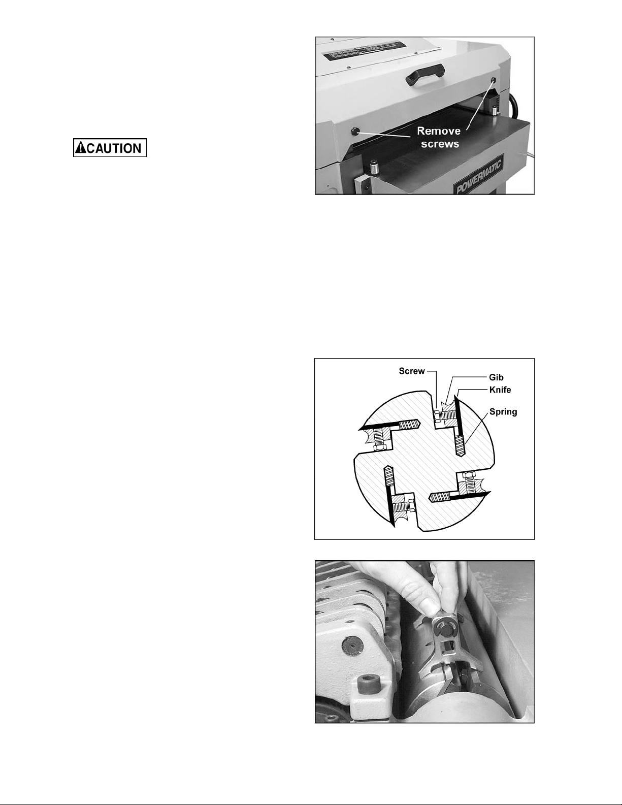
Opening Hood
To open the hood f or access to t he cutterhead,
remove the two hex screws with the 22mm
wrench provided. See Figure 7.
Knife Installation and Adjustment (Straight Cutterhead only)
Use care when p lacing hands
near knives as they are extremel y sharp and
can cause severe cuts.
Installing knives on a planer is an exacting
process. If the knives are not to be joi nted and
ground, end-to-end and knife-to-knife
relationship m ust be held within .001" (.03mm)
for accur ate and smooth plani ng. To help avoid
cutterhead distortion when changing out a set of
knives, rem ove and r eplac e the knife in one slot
before changing the next knife. Snug down each
knife until all four are ready to fully tighten, as
described below. It may be helpful to number
the knives with a f elt- tip marker to keep t rack of
progress.
Any knife adjustm ent or replacement should be
done to all four knives at t he same time. Failure
to do this may result in an out-of-balance
cutterhead which c an lead to bearing failure.
1. Disconnect machine from power source.
Figure 7
2. To remove a knife, loosen the ei ght screws
along its gib. See Fi gur e 8.
3. The springs will cause the knife to rise in the
slot. Carefull y remove knife from cutt erhead
by lifting straight out. Remove gib and
springs, and clean any dust, pitch or
accumulated foreign matter from the slot
and the gib.
4. Replace the springs and gib into the slot,
then insert new knife and lightly snug the
eight gib screws.
5. Place the knife-setting gauge on the
cutterhead as shown in Figure 9, with the
flanges resting upon t he cutterhead and the
center protr usion pu shing down upon t he ti p
of the knife. This will hold the high point of
the knife to the proper height above the
cutterhead (appr ox imately 1/8” or 3.18mm).
6. Use the gauge at both ends of the knife,
then check the center secti on to be sure it is
even. If the knife is low in the center, try
backing off slightl y on the center gib screw
to allow the blade to come up. Gently tap
blade down with a piece of wood until it
conform s to the gauge height. Re- check the
full length of the k nife.
Figure 8 – Model 201 only
Figure 9 – Model 201 only
10
Page 11

7. Rotate the cutterhead using the belt or
pulley, and repeat steps 2 through 6 for
each of the remaining three knives.
8. When all four knives have been installed
and made snug, begin the tightening
process.
NOTE: All knives and gibs should be in
place before tightening. Tightening one knife
in without the others in position can cause
cutterhead distortion.
9. The tightening process should proceed
working from the center outward on each
knife. Go onc e ar ound the cutterhead f ur ther
tightening all gib screws in sequence. Then
repeat the same sequence a second time,
this time full y tightening all screws.
After installing knives, re-
check all gib screws for tightness. Loose
gib screws can resu lt in knives b eing th rown
from the cu tterhead, cau sing severe damage
to the mach ine and possibl e serious or fat al
injury to t he ope r a t or or by s ta nders.
Replacing or Rotating Knife Inserts (Helical Cutterhead only)
The knife insert s on the model 201HH are f oursided. When dull, simply remove each insert,
rotate it 90° for a fresh edge, and re- install it.
No set-up gauge is necessary for the inserts.
Use the provided star point screwdriver to
remove the knif e insert screw. See Figure 10. It
is advisable to rotate all insert s at the same time
to maintain consistent cutting. However, if one
or more knife inserts develops a nic k , rotate only
those inserts that are affected.
Each knife insert has an etched referenc e mark
so that you can keep track of rotations.
IMPORTANT: When removing or rotating
inserts, clean saw dust from the screw, the
insert, and the cutterhead platform. Dust
accumulation between these elements can
prevent the insert from seating properly, and
may affect the quali ty of the cut.
Before installing each screw, lightly coat the
screw threads wit h m achine oi l and wi pe off any
excess.
Figure 10 – Model 201HH only
Securely tighten each screw which holds the
knife inserts before operating the planer!
Make sure all knife insert
screws are tigh ten ed secu rely. Loo se inserts
can be propelled at high speed from a
rotating cutterhead, causing injury.
11
Page 12

The Planer’s Feed System
(Refer to Figure 11)
1. Anti-kickback fingers
2. Infeed roller
3. Chipbreaker
4. Cutterhead
5. Pressure bar
6. Outfeed roller
Anti-Kickback Fingers
Anti-kickback fingers help prevent stock from
being thrown from the machine. These fingers
operate by grav ity and should be inspected f or
pitch or gum buildup befor e eac h day ' s us e. The
fingers must operate freely and move
independently for correct operation.
Infeed Roller
The function of the infeed roller is to feed the
material into the machine. It is a corrugated,
sectional roller with approximately 1/4"
independent movement of each section to
accommodate multiple board surfacing.
To provide pr oper drive, the infeed roll er should
be set so that the bottom of its arc is 1/16"
(1.6mm) bel ow the arc of t he cutt erhead k niv es.
The infeed r oller is under spring t ensi on and this
tension must be sufficient to feed the stock
uniformly through t he pl aner without slippi ng but
should not be so ti ght that i t causes damage to
the stock. T he tension should be equal at both
ends of the roller.
To adjust the infeed roller:
1. Disconnect machine from power source.
2. Place a dial gauge (not provided) under a
knife i n the c utt erhead. If a di al gauge i s not
available, use a finished block of wood with
notches cut out for the table rolls, in
conjunction wit h a feeler gauge. S ee Figure
13 for an exam ple of a wood block you can
make and use as a gauge.
3. Raise the tabl e with t he handwheel unt il the
gauge contacts a knife at the apex of its
curve. Zero the gauge at t hat position.
4. Move the gauge to the extreme left end of
the infeed roller and check the
measurement. It should be 1/16” bel ow the
knife measurement.
5. If it is not 1/16” below the k nife, correct by
loosening the hex nut and turning the
adjustment screw (A, Figure 14) with a hex
wrench.
Figure 11
Figure 12
12
Page 13

6. Move the gauge to t he extreme right end of
the infeed roller and check. Make similar
adjustments if needed.
7. Tighten hex nuts (A, Figure 14) when
finished.
IMPORTANT: The setting on both ends of the
infeed roll er must be the same to avoi d skewing
of the material as it is fed through the machine.
Chipbreaker
The chipbreak er is a sectionaliz ed type made of
spring-loaded secti ons mounted on a bar , which
complements the sectional infeed roller. The
functions of the chipbreaker are to break chips
into small pieces, help avoid splintering of the
wood, help avoid board bounce on thinner
boards, to direct the flow of chips out of the
machine, and to permi t multiple board surfacing.
The chipbreaker has been factory set at 1/32”
(0.8mm) below the cut ti ng arc of t he knives, and
has been spring-tensioned pr oper ly.
Figure 13
User-made Gauge Bloc k
A chipb reaker set too low or
with excessive tension may prevent stock
from feeding into th e machi ne.
Pressure Bar
Most planing problems can be traced to
improper sett ing of the pressure bar. It s f uncti on
is to hold down the mat eri al after it passes under
the cutter head and throughout the remainder of
the cut. I ts basic setting i s to be in li ne with the
arc of the cutterhead knives.
If the pressure bar is too high, a shallow "clip"
will occur at each end of the board. If it is too
low, stock will not f eed through.
Use a gauge to set the full length of the
pressure bar to be .000-.001" (.02mm) below
the arc of the cutter head.
Figure 15 shows the height adjustment screw
(C) and the spri ng ten sion adj ustm ent scre w (D)
for the pressure bar. Loosen the hex nut and
rotate the screw as needed. Make sure the
setting on both end s of the pressure bar is the
same. Tight en the hex nuts when adj ustment i s
complete.
Figure 14
This initial setup is a starting point and final
adjustment may have to be made during a test
cut.
Figure 15
13
Page 14

Outfeed Roller
The outfeed roller is of smooth, one-piece
construction to help avoid marring the finished
surface of the material being cut. It is spring
tensioned, and i ts f unct ion is to c onti nue to feed
the materi al through the machi ne after it leav es
the infeed roller. The correct free position
setting is 1/32" (0.8mm) below the arc of the
cutterhead knives.
Use a gauge, such as a bed and feed r oll gauge
or wood gauge block (see Figure 13) to check
the outf eed roll er i n the sam e manner as f or t he
infeed roller. Adjust as necessary using the
screws (E, Figur e 15). When fini shed adjusting,
tighten the hex nuts on the screws.
Table Rollers
The Planer has two table rollers which help
reduce friction of the stock on the table as it
feeds through t he machine. It is not possibl e to
give exact height setting of the table rollers
because each ty pe of wood beh aves di fferent ly.
As a general rule, however, the table rollers
should be set high when planing rough stock,
and set low for fi nish cut s.
The planer is equipped with a quick set table
roller adjustment. With a single lever, you can
raise the roll s from their fi nishing board hei ght to
a roughing board height. The range is 0.00 to
0.05”.
Figure 15 (repeated)
To adjust the hei ght of the table rollers, loosen
the handle (A, Figure 16) and move the quickset lever (B, Figure 16) until the indicator is at
the desired setti ng on the scale. Re-tighten the
handle (A, Figure 16) to lock the setting.
NOTE: The handle (A) is adjustable. To reposition it , simply lift out on the handle, rotat e it
on the pin and release, making sure it seats
itself properly on the pin.
The table rollers are adjusted at the factory. If
they should need further or “fine” adjustment:
1. Disconnect machine from power source.
2. Loosen lock handle and positi on the quick-
set lever (Fi gur e 16) to zero.
3. Use a dial gauge (not provi ded) to find the
distance from table top to the apex of the
table roller. Zero the gauge at this position.
4. Place t he gauge over the ex treme right side
of the t able roller and fi nd the high point of
the table roller arc. The gauge should still
read zero.
Figure 16
14
Page 15

5. If the gauge reading i s greater or le ss than
zero, reach beneat h the table with a wrench
and loosen the hex nut (C, F i gure 17) which
is above the cam (D, Figure 17) near the
end of the roller that needs adjusti ng. Rotate
the hex cap screw (E, Figure 17) until the
gauge reads zero.
6. Repeat the process for the left side of the
table roll er, and then r e-check the right side.
It is important that both ends of the table
roller be the same height to help prevent
skewing of t he board a s it f eeds through t he
machine.
7. Re-tighten the hex nuts (C, Figure 17) on
both ends of the table roller.
8. Repeat the procedure for the second table
roller.
Table Adjustments
The planer table is raised and lowered by twin
screws supported on beari ngs, and is guided by
machined surfaces on the side panels. The fitup to prevent the table from rocking is cont roll ed
by two gibs in front . See Figure 18. These gibs
are pre-set at the factory and require no
attention. If, after extensive use of the planer,
some looseness in the table develops, these
gibs can be adjusted individually using the gib
screws provided so that the ways are lightly
contacti ng on all four surfaces. The gibs sho uld
be tight enough t o prevent rocki ng or m ovem ent
of the table when the pl aner is i n operation.
Figure 17
Figure 18
To perform accurate planing, t he table must be
parallel wit h the cutter head. Lack of parall elism
results in a taper ov er the width of the board. T o
check parallelism do the following:
1. Pl ace a gauge on t he table and c ontacti ng a
knife at t he apex of its arc. Do t his at each
end of the cutterhead and compare the
measurements.
2. If the table is not parall el to the cutterhead,
place the gauge at the end t hat needs to be
raised.
3. Loosen the three socket head cap screws
(A, Figure 19) beneath the table.
4. Place a rod-like object (such as a hex
wrench) into one of the open holes (B,
Figure 19) and t urn the shaft ( C, Figure 19)
to raise the t able until the gauge reads the
proper measurement. Or, the same effect
can be achiev ed by lowering the other side
of the table.
5. Re-tighten the screws (A, Figure 19).
NOTE: Thi s adjustment may generate the need
to recalibrate the table height pointer.
Figure 19
15
Page 16

Operating Controls
The stop button is a mushroom style button
which is conv enient for “ emergency ” shutdowns.
After being pushed, the stop button remains
engaged. To re-start the planer, twist the stop
button clockwise until it pops back out.
Test Cutting and Troubleshooting
Using a piece of semi-finished stock, set up for a
1/16" (1.59mm) deep cut with t he quick-set table
roller adjustment (shown in Figure 16) set at
zero. Start the machine and, standing to one
side of the table, begin feeding the stock into the
machine.
Never stand directly in line
with stock or al lo w anyone else to do so, and
do not bend down to see how stock is
feeding. Shoul d a kickback occur, seriou s or
fatal injury could resul t .
The infeed roller should take the material and
force it under the chi pbreaker and cut terhead. I f
the materi al feeds through effortlessly, examine
the finished cut carefully for imperfections.
Learning to read a board for imperfections will
save hours in adjusting a planer to operate
properly.
Following are some problems that may arise
and their probable remedies. The Figure
illustrations are exaggerated for clarity. (Pages
19-21 also contai n Troubleshooting remedies).
Washboard Finish
A very pronounced washboard finish down the
full length of the board results from one knife
being too high and forced to do all the cutting.
See Figure 20. Re-set the high knife
accordingly.
Clip Marks
If "clip" marks occur 6" (152mm) in from each
end of the board, the pressure bar is too high.
See Figure 21. Turn both right and left hand
adjusting screws (see Figure 15) the same
amount, 1/4 turn clockwise or less, and take
another 1/16" (1.59mm) deep cut. Re-examine
the board.
Continue the operat e-adjust procedure until t he
clip marks disappear. Should the board fail to
feed through, back off sli ghtly on both adj usting
screws until feeding is smooth and the
imperfections do not re-appear. Lock the
pressure bar adj usting scre ws with t he jam nuts
provided.
Figure 20
(washboard)
Figure 21
(clip marks)
16
Page 17

Snipe
Some amount of snipe may be inevitable with
many planer operations, but proper planer
adjustments can so minimize snipe as to make it
negligible.
If noticeabl e snipes appear on each end of the
material, as shown in Fi gure 22, a tabl e rol ler is
too high causing a sl ight lift of t he material as it
passes through the machine. Normally these
snipes are more notic eable on the traili ng end of
the board than on the l ead end, and most of ten
occur during planing of rough lumber.
Table roll ers must be el ev ated for runni ng r ough
or resaw lumber through the machine. When
material i s turned over t o surf ace the ot her side,
and you neglect to lower the table rollers for a
finish cut, then def init e snipes will appear on the
ends of the material.
Chatter
Chatter marks usually appear on thin material.
See Figure 23. Even at their lowest point, the
table roll ers are too high to handle t hin material.
Solve the problem by either using a slav e board
or making an auxiliary table out of Formica
countertop m aterial with cleati ng at each end to
keep it stati onar y ov er the planer table.
Figure 22
(snipe)
Figure 23
(chatter)
Tapers
If the machine planes a taper across the full
width of the board, as shown in Fi gure 24, the
table is not parallel with the cutterhead. First
check that al l knives are properly inst alled with
equal protrusi on from the c utterhead. If they are,
then the table itself must be adjusted. See
“Table Adjustm ents” on page 15.
Twisting
If material twists while feeding through the
planer, the pr essure bar, out feed roller or table
rollers may be out of level. Ref er to adj ustment
settings on pages 13 and 14.
Feed Restriction
This is caused either by the table rollers being
set too low for roughi ng operations or by a low
pressure bar. A bout 90 percent of t he time the
pressure bar is too l ow. As the sharp edge of the
planer knives wear, you must compensate for
this wear by raising the pressure bar an equal
amount on each side. Your first indication of
knife wear is hesitation in feed of the material
through the machine after it leaves the
corrugated infeed roller on its way out of the
machine. Disconnect machine from power
and adjust the pressure bar acordingly. The
material will free up and feed thr ough smoothly
when the planer is restart ed.
Figure 24
(taper)
17
Page 18

Never attempt pressure bar
adjustment while planer is connected to
power.
Feed restriction can also occur due to pitch
buildup on the table. Be sure the table surface is
clean. Occasi onally dusti ng the surface with talc
will aid in smoother feeding and help prevent
pitch buildup.
Halted Feeding
If the infeed roller takes the stock, the
chipbreakers l ift, and just as you hear t he kniv es
contact the material, it stops feeding, then the
pressure bar i s too low. Re set the pressure bar
(see page 13).
Maintenance
Periodic inspecti ons are required to ensure that
the machine is in proper adjustment, that all
screws are tight, that belt s are in good condition,
that dust has not accumulated in the electrical
enclosures, and that t here are no loose or worn
electric al c onnec tions.
Buildup of sawdust and other debris can cause
your machine to plane inaccurately. Periodic
cleaning is not only recommended but
mandatory for accurate planing.
Close-fitting parts, such as the table locking
rods, the cutterhead slot and gibs, should be
cleaned with a cloth or brush and nonflammable solvent and freed from clinging
foreign matter.
Lubrication
The gear box oil should be changed at least
once a year. Rem ove the drain pl ug (A, Figure
25) to drain t he oi l i nt o an appropri ate c ontai ner.
Replace the drai n plug and f ill t he gear box wit h
60 to 90 weight gear oi l through the fill hole (B,
Figure 25). Capacit y is 0.494 gall on (1. 87L). The
sight glass (C, Figure 25) should be checked
periodical ly and oil topped off as necessary.
Figure 25
The recommended lubrication for roller chains
used in medium to slow speed operation is to
simply wipe the chain clean. When there is an
appreciable buildup of dust, dirt or wood
shavings, use an oi l clot h but never pour t he oil
directly on the chain. Over-oiling defeats the
purpose of t he l ubricati on, sinc e it t ends to i nvite
the collection of dust, shavings, etc. and works
into members of the chain. This hastens wear
and leads to prematur e r eplac em ent.
Use caution and proceed
slowly when working with or around the
cutterhead kni ves.
Remove resin and other accumulations from
feed rolls and table with a non-flammable
solvent.
Periodically check all the chains and belts for
proper tension and adjust accordingly if
required.
TIP: If a f oreign object nicks the kniv es on the
straight cutterhead (Model 201), instead of
throwing them away or trying to grind out the
deep nick, simply stagger the knives in the
head, moving one k nife no mor e than 1/4” to the
right and another knif e no m ore than 1/4” t o the
left. The nick will not be noti c eable.
The bearings on the cutterhead are factory
lubricated and sealed. They require no further
attention.
Periodically oil the bearings on the infeed and
outfeed roll ers, through the oil cups located on
the bearing block s (Fi gur e 26) .
Figure 26
18
Page 19

Troubleshooting: Planer Operating Problems
Trouble Probable Cause Remedy
Table rollers not set pr oper ly. Adjust tabl e rollers to proper height.
Snipe.
Fuzzy grain.
Torn grain.
Inadequate support of long boards.
Uneven feed roller pr essure front to
back.
Dull knives.
Lumber not butt ed pr operl y .
Planing wood with a high moisture
content.
Dull knives.
Too heavy a cut. Adjust proper dept h of cut.
Knives cutti ng against grain. Try to cut with the grai n for finish cut.
Dull knives.
Dull knives.
Support long boar ds with a r oller
stand.
Adjust feed roller tension.
Sharpen or replac e k niv es.
Rotate or replace k nife inserts.
Butt end-t o- end eac h piec e of stock
as they pass through.
Remove moisture from wood by
drying, or use different stock.
Sharpen or replac e k niv es.
Rotate or replace k nife inserts.
Sharpen or replac e k niv es.
Rotate or replace k nife inserts.
Sharpen or replac e k niv es.
Rotate or replace k nife inserts.
Rough/raised grai n.
Rounded, glossy
surface.
Poor feeding of
lumber.
Excessive dept h of cut. Decrease cutti ng depth.
Moisture cont ent too high.
Dull knives.
Inadequate f eed r oller pressure.
Planer table r ough or dir ty.
Belts are slipping.
Surface of feed rollers has been worn
too smooth.
Remove moisture from wood by
drying, or use different stock.
Sharpen or replac e k niv es.
Rotate or replace k nife inserts.
Adjust feed roller tension. If proper
tension cannot be achieved, replace
feed roller(s).
Clean off pitch and r esi due; apply
light coat of paste wax to planer table.
Check belt tension and m ak e any
needed adjustments.
Lightly roughen t he feed roller surface
with sandpaper.
19
Page 20

Troubleshooting: Mechanical and Electrical Problems
Trouble Probable Cause Remedy
Uneven depth of cut
side to side.
Board thickness does
not match dept h of
cut scale.
Chain is jumpi ng.
Machine will not
start/restart or
repeatedly trips
circuit breaker or
blo ws fuses.
Knives not set corr ec tly.
Planer table not parallel to cutterhead.
Depth of cut scale is inc or r ect. Adjust pointer on depth of cut scale.
Inadequate chain tension. Adjust chai n tension.
Sprockets mi sali gned. Align sprockets.
Sprockets worn. Replace sprockets.
No incoming power. Verify machine is connected to power.
Stop button is stil l engaged. Rotate stop button to disengage.
Overload automatic reset has not
reset.
Planer frequently trips.
Building circuit breaker trips or fuse
blows.
Loose electri c al c onnec tions.
Make sure knives are set correctly
and securely in c utt er head.
Adjust tabl e parallel to cutterhead.
See page 15.
When the planer overloads on the
circuit breaker built into the motor
starter, it takes time for the machine
to cool down before restar t. Allow
machine to adequately cool before
attempting r estar t. If problem persists,
check amp setting on t he m otor
starter insi de the electrical box.
One cause of overl oad trips which are
not electrical in nature is too deep a
cut. The solution is to take a lighter
cut. If too deep a cut is not the
problem, check the amp setting on
the overload r elay . Match the full load
amps on the motor as noted on the
motor plate.
If amp setting is corr ec t, then t here is
probably a loose electrical lead or a
failed component . S ee items below.
Verify that planer is on a circuit of
correct size. If circuit size is correct,
there is probabl y a loose el ectr ic al
lead. Check am p setting on motor
starter.
Go through all of the electrical
connections on the planer including
motor connecti ons, verifying the
tightness of eac h. Look for any signs
of electrical ar ci ng whic h is a sure
indicator of loose connections or
circuit overload.
20
Page 21

Trouble Probable Cause Remedy
Machine will not
start/restart or
repeatedly trips
circuit breaker or
blo ws fuses.
(continued)
Starter or motor failure (how to
distinguish).
Motor failure. If electri c mot or i s suspect, you have
Examine motor star ter for burned or
failed component s. If dam age is
found, replace motor starter.
If you have access to a voltmeter, you
can separate a starter f ailure from a
motor fai lu re by fi r st, verifyin g
incoming volt age at 220+/-20 and
second, checking the voltage
between starter and motor at 220+/-
20.
If incoming voltage is incorrect, you
have a power supply probl em .
If voltage between starter and motor
is incorrect, you have a starter
problem.
If voltage between starter and motor
is correct, you hav e a motor pr oblem.
two options: Have a qualified
electrican test the motor for function
or remove the motor and take it t o an
electric motor repai r shop and have it
tested.
Machine incorr ec tly wired. Double check to confi rm all electrical
connections are cor r ec t. Refer to
appropriate wir ing diagrams on pages
34-36 to make any needed
corrections.
Start/ stop switc h failure. If a start or stop switch is suspect, you
have two options: Have a qualified
electrician test the switch for function,
or purchase a new switch and
establish if t hat was the problem on
changeout.
Planer does not
come up to speed.
Low current. Contact a qualified electrician.
Replacement Parts
Replacement par ts are li sted on the f ollowing page s. To order parts or reac h our servi ce depar tm ent, call
1-800-274-6848, Monday through Friday (see our website for business hours, www.powermatic.com).
Having the Model Number and Serial Number of your mac hine available when you cal l will allow us to
serve you quickly and accurately.
21
Page 22

Parts List: Base Assembly
Index No. Part No. Description Size Qty
1 ............... 6012068...................Rubber Boot .......................................................................................... 2
2 ............... 6012069...................Lead Screw ........................................................................................... 1
3 ............... 6293370...................Key.....................................................................5 x 5 x 10 ................... 2
4 ............... 6012070...................Screw w/ Washer............................M4x0.7Px8Lg / 4mmx10x0.8T ......... 4
5 ............... 6012071...................Bushing ................................................................................................. 2
6 ............... 6012072...................R-Ring ................................................................RTW-68 ...................... 2
7 ............... 6012073...................Ball Bearing ........................................................6008-2NSE ................. 2
8 ............... 6012074...................Bearing...............................................................51105 ......................... 4
9 ............... 6012066...................Socket Head Cap Screw .....................................M8 x 1.25P x 25Lg .... 11
10 ............. 6012075...................Bracket .................................................................................................. 2
11 ............. 6012076...................Sprocket ................................................................................................ 3
12 ............. 6012077...................Washer...............................................................25mm ......................... 2
13 ............. 6012078...................Nut .....................................................................M25 x 1.5 ................... 2
14 ............. 6012079...................Hex Nut .............................................................M10 x 1.5P ................. 5
15 ............. 6012080...................Flat Washe r ........................................................10mm x 25 x 3T .......... 1
16 ............. 6012081...................Rocker Arm ........................................................................................... 1
17 ............. 6012082...................Shaft ..................................................................................................... 1
18 ............. 6012083...................Flat Washe r ........................................................8.5mm x 19 x 2T ......... 2
19 ............. 6012067...................Spring Was her....................................................8.2 mm x 15.4.............. 5
20 ............. 6012084...................Lead Screw ........................................................................................... 1
22
Page 23

21 ............. 6292745...................Key.....................................................................5 x 5 x 16 ................... 2
22 ............. 6012085...................Chain .................................................................#40 x 79pcs ................ 1
23 ............. 6012086...................Bevel Gear ............................................................................................ 1
24 ............. 6012087...................Screw .................................................................M5 x 0.8P x 10Lg........ 4
25 ............. 6012088...................Strain Relief Clip .................................................ACC-3 ........................ 4
26 ............. 6012089...................Pin......................................................................................................... 4
27 ............. 6012090...................Base ...................................................................................................... 1
28 ............. 6012091...................Screw .................................................................M6 x 1.0P x 10Lg...... 12
29 ............. 6012092...................Cover .................................................................................................... 2
30 ............. 6012093...................Special Hex Screw ................................................................................ 4
31 ............. 6012094...................Hex Nut ..............................................................M16 x 2.0 ................... 4
32 ............. 6012095...................Foot ....................................................................................................... 4
33 ............. 6012096...................Set Screw ...........................................................M8 x 1.25P x 30Lg ...... 1
34 ............. 6012097...................Hex Nut ..............................................................M8 x 1.25 ................... 3
35 ............. 6012098...................Set Screw ...........................................................M5 x 0.8P x 5Lg ......... 2
36 ............. 6012099...................Bevel Gear ............................................................................................ 1
37 ............. 6012100...................S-Ring ................................................................STW-20 ...................... 1
38 ............. 6012101...................Ball Bearing ........................................................6204-ZZ ..................... 1
39 ............. 6012102...................Support Block ........................................................................................ 1
40 ............. 6012103...................Shaft ..................................................................................................... 1
41 ............. 6012104...................Key.....................................................................8 x 7 x 18 ................... 1
42 ............. 6012105...................Ball Bearing ........................................................6005-ZZ ..................... 1
43 ............. 6012106...................Chain .................................................................#40 x 107pcs .............. 1
44 ............. 6012107...................Sprocket ................................................................................................ 1
45 ............. 6012052...................S-Ring ................................................................STW-25 ...................... 1
46 ............. 6012109
47 ............. 6012110...................Power Cord ........................................................1Ph ............................ 1
................. 6012267...................Power Cord ........................................................3Ph ............................ 1
48 ............. 6012111...................Switch ................................................................ 460V/3Ph ................... 1
................. 6012045...................Switch ................................................................230V/1Ph ................... 1
................. 6012294...................Switch ................................................................230V/3Ph ................... 1
49 ............. 6012112...................Switch Plate .......................................................................................... 1
50 ............. 6012113...................Strain Relief Bushing ..........................................M20 ............................ 1
51 ............. 6012114...................Cover .................................................................................................... 1
52 ............. 6012115...................Motor Cord .........................................................1Ph ............................ 1
................. 6012266...................Motor Cord .........................................................3Ph ............................ 1
53 ............. 6012048...................Socket Head Cap Screw .....................................M10 x 1.5P x 20Lg ...... 1
54 ............. 6012116...................Washer.................................................................................................. 1
55 ............. 6012117...................Belt.....................................................................A56 ............................ 1
56 ............. 6012118...................Motor Pulley .......................................................................................... 1
57 ............. 6012108...................Motor ..................................................................7.5HP 1Ph 230V ......... 1
................. 6012108-SC.............Start Capacitor ...................................................200MFD, 250VAC ...... 2
................. 6012108-RC ............Run Capacitor ....................................................20μF,450VAC ............. 1
................. 6012108-RC2 ..........Run Capacitor ....................................................35μF,450VAC ............. 1
................. 6012119...................Motor ..................................................................7.5HP 3Ph 230/460V .. 1
................. 2210-271 .................Key.....................................................................8x7x40 mm.................. 1
58 ............. 6012120...................Flat Washe r ........................................................10.3mm x 23 x 2T ....... 8
59 ............. 6012121...................Hex Nut ..............................................................M12 x 1.75 ................. 4
60 ............. 6012122...................Flat Washe r ........................................................13mm x 28 x 3T .......... 4
61 ............. 6012123
62 ............. 6012124...................Set Screw ...........................................................M8 x 1.25P x 12Lg ...... 5
63 ............. 6012125...................Spacer................................................................................................... 2
64 ............. 6012126...................Shaft ..................................................................................................... 2
65 ............. 6012127...................Motor Plate ............................................................................................ 1
66 ............. 6012128...................Hex Screw ..........................................................M10 x 1.5P x 40Lg ...... 4
67 ............. 6012129...................Set Screw ...........................................................M8 x 1.25P x 20Lg ...... 2
68 ............. 6012130...................Flat Head Screw .................................................M6 x 1.0P x 20Lg........ 4
69 ............. 6012269...................Terminal Cover ...................................................................................... 1
70 ............. 6012270...................Screw .................................................................3/16-24NC x 1/4 ......... 1
71 ............. 6012271...................Screw .................................................................M5 x 0.8P x 20L ......... 2
72 ............. 6012272...................Termina l Plate ....................................................................................... 1
...................Switch Cord ........................................................................................... 1
...................Adjusting Bolt ........................................................................................ 2
23
Page 24

Gearbox Assembly
24
Page 25

Parts List: Gearbox Assembly
Index No. Part No. Description Size Qty
................. 201-100 ...................Gearbox Assembly ................................................................................ 1
1 ............... 6012034...................Gearbox Body ....................................................................................... 1
2 ............... 6012035...................Ball Bearing ........................................................6201-2NSE ................. 6
3 ............... 6012036...................S-Ring ................................................................STW-16 ...................... 2
4 ............... 6012037...................Gear ...................................................................................................... 2
5 ............... 6012038...................Ball Bearing ........................................................6204-2NSE ................. 2
6 ............... 6012039...................Oil Seal ..............................................................TC24 x 40 x 8 ............. 1
7 ............... 6012040...................Shaft ..................................................................................................... 1
8 ............... 6293370...................Key.....................................................................5 x 5 x 10 ................... 4
9 ............... 6012041...................Gear ...................................................................................................... 2
10 ............. 6012042...................Gasket................................................................................................... 1
11 ............. 6012043...................Pin......................................................................................................... 4
12 ............. 6012044...................Gearbox Cover ...................................................................................... 1
13 ............. 6012142...................Hex Socket Ca p Sc re w .......................................M10 x 1.5P x 25Lg ...... 4
14 ............. 6012046...................Pulley .................................................................................................... 1
15 ............. 6012047...................Flat Washe r ........................................................10mm x 25 x 3T .......... 2
16 ............. 6012048...................Socket Head Cap Screw .....................................M10 x 1.5P x 20Lg ...... 1
17 ............. 6012049...................Socket Head Cap Screw .....................................M8 x 1.25P x 20Lg ...... 1
18 ............. 6012050...................Sprocket ................................................................................................ 1
19 ............. 6292789...................Oil Plug ..............................................................PT1/4"-19UNF ............ 2
20 ............. 33-1051-00-1 ...........Oil Seal ..............................................................TC20 x 40 x 7 ............. 1
21 ............. 6012051...................Shaft ..................................................................................................... 1
22 ............. 6012052...................S-Ring ................................................................STW-25 ...................... 1
23 ............. 6292745
24 ............. 6012053...................Shaft ..................................................................................................... 1
25 ............. 6012054...................Gear ...................................................................................................... 1
26 ............. 6012055...................Shaft ..................................................................................................... 1
27 ............. 6012056...................Gear ...................................................................................................... 1
28 ............. 6012057...................Gear Assembly ...................................................................................... 1
29 ............. 6012058...................Set Screw ...........................................................M5 x 0.8P x 5Lg ......... 1
30 ............. 6012059...................Spring Pin...........................................................4mm x 25Lg ............... 1
31 ............. 6012060...................Shift Fork ............................................................................................... 1
32 ............. 6012061...................Lever ..................................................................................................... 1
33 ............. 6012062...................E-Ring ................................................................ETW-12 ...................... 1
34 ............. 6012063...................Shift Shaft.............................................................................................. 1
35 ............. 6012064...................Eye Glass Oil Lev el ............................................................................... 1
36 ............. 6012065...................Spring Pin...........................................................5mm x 26Lg ............... 1
37 ............. 6012066...................Socket Head Cap Screw .....................................M8 x 1.25P x 25Lg ...... 3
38 ............. 6012067...................Spring Was her....................................................8.2 mm x 15.4.............. 4
39 ............. 6012082...................Shaft ..................................................................................................... 1
40 ............. 6012286...................Idle Sprocket ......................................................................................... 1
41 ............. 6012287...................Bracket .................................................................................................. 1
42 ............. 6012079...................Hex Nut ..............................................................M10 x 1.5P ................. 1
43 ............. 6012288...................Stand Off ............................................................................................... 1
44 ............. 6012289...................Check Nut ..........................................................M10 x 1.5P ................. 1
45 ............. 6012290...................E-Ring ................................................................ETW-7 ........................ 1
46 ............. 6012291...................Spring .................................................................................................... 1
47 ............. 6012292...................Stand Off ............................................................................................... 1
...................Key.....................................................................5 x 5 x 16 ................... 2
25
Page 26

Column Assembly
26
Page 27

Parts List: Column Assembly
Index No. Part No. Description Size Qty
1 ............... 6012193...................Lifting Eye ..........................................................M20 x 2.5P x 30Lg ...... 2
2 ............... 6012194...................Left Column ........................................................................................... 1
3 ............... 6012195...................Pin......................................................................................................... 4
4 ............... 6012079...................Hex Nut ..............................................................M10 x 1.5P ................. 1
5 ............... 6012080...................Flat Washer ........................................................10mm x 25 x 3T ........ 1 7
7 ............... 6012066...................Socket Head Cap Screw .....................................M8 x 1.25P x 25Lg ...... 6
8 ............... 6012067...................Spring Washe r....................................................8.2mm x 15.4.............. 7
9 ............... 6012083...................Flat Washer ........................................................8.5mm x 19 x 2T ......... 2
10 ............. 6012082...................Shaft ..................................................................................................... 1
11 ............. 6012197...................Sprocket ................................................................................................ 3
12 ............. 6012157...................Spring Was her....................................................10 .2mm x 18.4.......... 1 6
13 ............. 6012198...................Socket Head Cap Screw .....................................M10 x 1.5P x 40Lg ...... 2
14 ............. 6012199...................Pan Head Machine Screw ..................................M4 x 0.7P x 10Lg........ 4
15 ............. 6012200...................Spring Was h e r....................................................4.1 m m x 7.7 ............... 4
16 ............. 6012201...................Flat Washe r ........................................................4.3mm x 10 x 1T ......... 5
17 ............. 6012202...................Switch Box ............................................................................................ 2
18 ............. 6012203...................Left Sidecover ....................................................................................... 1
19 ............. 6012091...................Screw .................................................................M6 x 1.0P x 10Lg...... 16
20 ............. 6012204...................Hex Nut ..............................................................5/16”-18NC ................. 1
21 ............. 6012205...................Idler Assembly ....................................................................................... 1
22 ............. 6012206...................Stand Off ............................................................................................... 2
23 ............. 6012207...................Stop Switch ........................................................................................... 1
24 ............. 6012208...................Start Sw itch ........................................................................................... 1
25 .............
26 ............. 6012210...................Spring .................................................................................................... 1
27 ............. 6012211A ................Shifter Hub ............................................................................................ 1
28 ............. 6012212...................Set Screw ...........................................................M6 x 1.0P x 12Lg........ 1
29 ............. 6012213...................Shaft ..................................................................................................... 1
30 ............. 6012214...................Handle................................................................................................... 1
31 ............. 6012087...................Screw .................................................................M5 x 0.8P x 10Lg........ 4
32 ............. 6012088...................Cord Clip ............................................................A CC-3 ........................ 4
33 ............. 6012156...................Socket Head Cap Screw .....................................M10 x 1.5P x 35Lg .... 14
34 ............. 6012215...................Right Column......................................................................................... 1
35 ............. 6012216...................Ball Bearing ........................................................6004ZZ....................... 1
36 ............. 6293370...................Key.....................................................................5 x 5 x 10 ................... 1
37 ............. 6292745...................Key.....................................................................5 x 5 x 16 ................... 1
38 ............. 6012217...................Shaft ..................................................................................................... 1
39 ............. 6012218...................Housing ................................................................................................. 1
40 ............. 6012219...................Sleeve ................................................................................................... 1
41 ............. 6012220...................Socket Head Cap Screw .....................................M6 x 1.0P x 16Lg........ 2
42 ............. 6012221...................Rocker Arm ........................................................................................... 1
43 ............. 6012222...................Right Cover ........................................................................................... 1
44 ............. 6012223...................Handwheel ............................................................................................ 1
45 ............. 6012224...................Lock Knob ............................................................................................. 1
46 ............. 6012225...................Handwheel Swiv el A ssembly ................................................................. 1
47 ............. 6012226...................Label Shift er .......................................................................................... 1
48 ............. 6012227...................Rivet ...................................................................................................... 6
49 .............
51 ............. 6012230...................Scale ..................................................................................................... 1
52 ............. 6012293...................Hex Nut ..............................................................M20 x 2.5 ................... 1
53 ............. 6012231...................Height Adjust Label ............................................................................... 1
54 ............. 6012201...................Flat Washe r ........................................................4.3 x 10 x 1T .............. 1
55 ............. 6012232...................Screw .................................................................M4 x 0.7P x 8Lg ......... 1
6012209...................Ball Detent..........................................................6mm ........................... 1
6012228...................Pointer................................................................................................... 1
27
Page 28

Table Assembly
28
Page 29

Parts List: Table Assembly
Index No. Part No. Description Size Qty
1 ............... 6012233...................Bracket .................................................................................................. 4
2 ............... BB-6203ZZ ..............Ball Bearing ........................................................6203-ZZ ..................... 4
3 ............... 6012234...................Roller Assembly .................................................................................... 2
4 ............... 6012079...................Hex Nut ..............................................................M10 x 1.5P ................. 4
5 ............... 6012235...................Hex Screw ..........................................................M10 x 1.5P x 30Lg ...... 4
6 ............... 6012236...................Hex Screw ..........................................................M8 x 1.25P x 16Lg ...... 2
7 ............... 6012237...................Hex Screw ..........................................................M6 x 1.0P x 16Lg........ 2
8 ............... 6012238...................Hex Screw ..........................................................M10 x 1.5P x 50Lg ...... 2
9 ............... 6012239...................Pointer................................................................................................... 2
10 ............. 6012240...................Plate ...................................................................................................... 2
11 ............. 6012241...................Plate ...................................................................................................... 2
12 ............. 6012097...................Hex Nut ..............................................................M8 x 1.25P ................. 9
13 ............. 6012242...................Set Screw ...........................................................M8 x 1.25P x 35Lg ...... 6
14 ............. 6012243...................Table ..................................................................................................... 1
15 ............. 6012244...................Table Adjusting Hub .............................................................................. 2
16 ............. 6012245...................Bushing ................................................................................................. 2
17 ............. 6012070...................Screw w/Washer..........................M4 x 0.7P x 8Lg/4mm x 10 x 0.8T ...... 4
18 ............. 6012083...................Flat Washe r ........................................................8.5mm x 19 x 2T ....... 10
19 ............. 6012067...................Spring Was her....................................................8.2 mm x 15.4.............. 6
20 ............. 6012246...................Socket Head Cap Screw .....................................M8 x 1.25P x 40Lg ...... 6
21 ............. 6012048...................Socket Head Cap Screw .....................................M10 x 1.5P x 20Lg ...... 2
22 .............
23 ............. 6012098...................Set Screw ...........................................................M5 x 0.8P x 5Lg ......... 6
24 ............. 6012247...................Special Screw........................................................................................ 2
25 ............. 6012248...................Linking Plate .......................................................................................... 3
26 ............. 6012249...................Shaft ..................................................................................................... 1
27 ............. 6012250...................E-Ring ................................................................ETW-24 ...................... 1
28 ............. 6012251...................Set Screw ...........................................................M6 x 1.0P x 12Lg........ 1
29 ............. 6012252...................Hub ....................................................................................................... 1
30 ............. 6012213...................Shaft ..................................................................................................... 1
31 ............. 6012214...................Handle................................................................................................... 1
32 ............. 6293370...................Key.....................................................................5 x 5 x 10 ................... 3
33 ............. 6012253...................Handle................................................................................................... 1
34 ............. 6012254...................Fixing Pla te ........................................................................................... 1
35 ............. 6012255...................Fixing Pla te ........................................................................................... 1
36 ............. 6012256...................Pointer ................................................................................................... 1
37 ............. 6012257...................Flat Washe r ........................................................5.3mm x 12 x 1T ......... 1
38 ............. 6012087...................Screw .................................................................M5 x 0.8P x 10Lg........ 1
39 ............. 6012258...................Special Screw........................................................................................ 1
40 ............. 6012259...................Socket Head Cap Screw .....................................M8 x 1.25P x 16Lg ...... 4
41 ............. 6012260...................Shaft ..................................................................................................... 4
42 ............. 6012261...................Cam ...................................................................................................... 4
43 ............. 6012262...................Transfer Rod ......................................................................................... 2
44 ............. 6012263...................Spring Pin...........................................................5mm x 26L ................. 4
45 ............. 6012264...................Label ..................................................................................................... 1
46 ............. 6012227...................Rivet ...................................................................................................... 2
47 ............. 6012228...................Pointer ................................................................................................... 1
48 ............. 6012265...................Name Label ........................................................................................... 1
49 ............. 6012201...................Flat Washe r ........................................................4.3mm x 10 x 1.0 T ...... 1
50 ............. 6012232...................Screw .................................................................M4 x 0.7P x 8 Lg ........ 1
6012080...................Flat Washer ........................................................10mm x 25 x 3T .......... 2
29
Page 30

Parts List: Top Cover Assembly
Index No. Part No. Description Size Qty
1 ............... 6012181...................Dust Hood ............................................................................................. 1
2 ............... 6012091...................Screw .................................................................M6 x 1.0P x 10Lg...... 1 8
3 ............... 6012182...................Spring Washe r....................................................6.1mm x 12.3............ 18
4 ............... 6012183...................Flat Washer ........................................................6.6mm x 13 x 1T ....... 18
5 ............... 6012184...................Upper Cover .......................................................................................... 1
6 ............... 6012066...................Socket Head Cap Screw .....................................M8 x 1.25P x 25Lg .... 10
7 ............... 6012185...................Cast Hinge Half ..................................................................................... 4
8 ............... 6012079...................Nut .....................................................................M10 x 1.5P ................. 4
9 ............... 6012186...................Socket Head Cap Screw .....................................M10 x 1.5P x 60Lg ...... 2
10 ............. 6012187...................Deflection Plate ..................................................................................... 1
11 ............. 6012188...................Top Cover ............................................................................................. 1
12 ............. 6012189...................Handle................................................................................................... 1
13 ............. 6012067...................Lock Wash e r ......................................................8.2mm x 15.4.............. 6
14 ............. 6012097...................Hex Nut ..............................................................M8 x 1.25P ............... 10
15 ............. 6012190...................Special Screw........................................................................................ 2
16 ............. 6012191...................Cylinder ................................................................................................. 2
17 ............. 6012192...................Warning Label ....................................................................................... 1
18 ............. 6012282...................Screw w / Wash e r................................................M 6 x 1.0P x 10Lg........ 4
19 ............. 6012283...................Shoulder Screw ..................................................................................... 2
20 ............. 6012284...................Shoulder Screw ..................................................................................... 2
21 ............. 6012285...................Check Nut ..........................................................M8 x 1.25P ................. 2
30
Page 31

Cutterhead Assembly
31
Page 32

Parts List: Cutterhead Assembly
Index No. Part No. Description Size Qty
1 ............... 6012131...................Socket Head Cap Screw .....................................M10 x 1.5P x 75Lg ...... 2
2 ............... 6012080...................Flat Washer ........................................................10mm x 25 x 3T ........ 10
3 ............... 6012132...................Spring.................................................................................................... 2
4 ............... 6012133...................Socket Head Cap Screw .....................................M10 x 1.5P x 50Lg ...... 2
5 ............... 6012079...................Hex Nut ..............................................................M10 x 1.5P ................. 8
6 ............... 6012134...................Pressure Bar Casti ng............................................................................. 1
7 ............... 6012048A ................Socket Head Cap Screw (LH Thread) .................M10 x 1.5P x 20Lg ...... 2
8 ............... 6012135...................Washer.................................................................................................. 2
9 ............... 6012136...................Sprocket ................................................................................................ 3
10 ............. 6012137...................Chain (infeed r oller to outfeed roller) ...................#40 x 60 pcs ............... 1
................. 201-BHA ..................Bearing Housing Assembly (index #11-15,18,72,78) .............................. 4
11 ............. 6012138...................Socket Head Cap Screw .....................................M6 x 1.0P x 16Lg........ 8
12 ............. 6012139...................Plate
................. 6012139A ................Plate
13 ............. 6012140...................Set Screw ...........................................................M8 x 1.25P x 25Lg ...... 4
14 ............. 6012097...................Hex Nut ..............................................................M8 x 1.25P ................. 4
15 ............. 6012141...................Bearing Housing .................................................................................... 4
................. 6012141A ................Bearing Housing
16 ............. 6012104...................Key.....................................................................8 x 7 x 18 ................... 1
17 ............. 6012143...................Outfeed Roller ....................................................................................... 1
18 ............. 6012144...................Needle Bearing ...................................................NA-6906 ..................... 4
19 ............. 6012048...................Hex Socket Cap Screw (LH Threads) .................M10 x 1.5P x 20Lg ...... 7
20 ............. 6012116...................Washer.................................................................................................. 1
21 ............. 6012145...................Belt.....................................................................A81 ............................ 2
22 ............. 6012146...................Cutterhead Pulley .................................................................................. 1
23 ............. 6012147...................Bushing ................................................................................................. 1
24 ............. 6012148...................R-Ring ................................................................RTW-85 ...................... 1
25 ............. 6012149...................Ball Bearing ........................................................6209-2NSE ................. 1
26 ............. 6012150...................Set Screw ...........................................................M8 x 1.25P x 10Lg ...... 8
27 ............. 6012151...................Cutterhead Casting Left ......................................................................... 1
28 ............. 6012152...................Shaft ..................................................................................................... 2
29 ............. 6012153...................Shaft ..................................................................................................... 2
30 ............. 6012154...................Cutterhead * .......................................................................................... 1
31 ............. 6012155...................Ball Bearing ........................................................6007-2NSE ................. 1
32 ............. 6012156...................Socket Head Cap Screw .....................................M10 x 1.5P x 35Lg ...... 6
33 ............. 6012157...................Spring Was her....................................................10 .2mm x 18.4............ 4
34 ............. 6012158...................Cutterhead Casting Right....................................................................... 1
35 ............. 6012159...................Screw *...............................................................M5 x 0.8P x 12Lg...... 12
36 ............. 6012160...................Knife Gib * ............................................................................................. 4
37 ............. 6012161...................Washer.................................................................................................. 8
38 .............
6012162...................Spring.................................................................................................... 4
39 ............. 6012163...................Shaft ..................................................................................................... 4
40 ............. 6012150...................Set Screw ...........................................................M8 x 1.25P x 10Lg ...... 4
41 ............. 6012164...................Spacer................................................................................................... 2
42 ............. 6012165...................Key.....................................................................8 x 7 x 30 ................... 1
43 ............. 6012166...................Infeed Shaft ........................................................................................... 1
44 ............. 6012167...................Infeed Roller ........................................................................................ 22
45 ............. 6012168...................Shaft ................................................................................................. 132
46 ............. 6012169...................Spring ................................................................................................ 132
47 ............. 6012170...................Shaft ..................................................................................................... 2
48 ............. 6012098...................Set Screw ...........................................................M5 x 0.8P x 5Lg ......... 1
49 ............. 6012171...................Stock Limiter ......................................................................................... 1
50 ............. 6012172...................Shaft ..................................................................................................... 2
51 ............. 6012173...................Bracket, Left Hand ................................................................................. 1
52 ............. 6012174...................Sectional Chipbreaker ......................................................................... 10
53 ............. 6012175...................Spring .................................................................................................. 10
(s/n 1306201HH0429 and higher)
(s/n 1301201HH0426 and lower)........................................................ 4
(s/n 1306201HH0429 and higher) ...................................................... 4
(s/n 1306201HH0429 and higher) . ................................... 4
32
Page 33

54 ............. 6012176...................Bracket, Right Hand .............................................................................. 1
55 ............. 6012177...................Spacer................................................................................................. 7 2
56 ............. 6012178...................Anti-Kic kb a c k Finger ............................................................................ 62
57 ............. 6012179...................Knife (set of 4) * ..................................................................................... 1
58 ............. 6012180...................Gib Screw * ......................................................................................... 32
59 ............. 6012273...................Spring .................................................................................................... 2
60 ............. 6012274...................Chain (gearbox to outfeed roller).........................#40 x 72 pcs ............... 1
61 ............. 6012275...................Shaft ..................................................................................................... 1
62 ............. 6012276...................Idle Sprocket ......................................................................................... 1
63 ............. 6012277...................Bracket .................................................................................................. 1
64 ............. 6012278...................Shaft ..................................................................................................... 1
65 ............. 6012279...................Check Nut ..........................................................M8 x 1.25P ................. 1
66 ............. 6012083...................Flat Washe r ........................................................8.5mm x 19 x 2T ......... 1
67 ............. 6012280...................Socket Head Cap Screw .....................................M8 x 1.25P x 50Lg ...... 1
68 ............. 6012281...................Spring .................................................................................................... 1
69 ............. 6012097...................Hex Nut ..............................................................M8 x 1.25P ................. 2
70 ............. 6012296...................Spring * ................................................................................................. 8
71 ............. 201-KGA ..................Knife Setting Gauge Assembly (i ndex #71- 1 thru #71- 3) (not shown)* .... 1
71-1 .......... 6012295...................Knife Setting Gauge (not shown) * ......................................................... 2
71-2 .......... 6284833...................Shaft (not shown) * ................................................................................ 1
71-3 .......... 6284834...................E-Ring (not shown) *.............................................................................. 4
72 ............. 201-672 ...................Retainer Ring ........................................................................................ 4
73 ............. 201-673 ...................Retainer Ring ........................................................................................ 4
................. 1791225A ................Helical Cutter
74 ............. 201HH-674A ............Helical Cutterhead ** ............................................................................. 1
75 ............. 1791212...................Knife Insert (sold in set of 10) ** .................................................. 125 total
76 ............. JWP208HH-111 .......Knife Insert Screw ** ...........................................#10-32 x 1/2” .......... 125
77 ............. JJ6HH-113 ...............Star Point Screwdriver (not shown)** ..................................................... 2
78 ............. WP2510-71 ..............Oil Cup
head Assembly (index #74 thru #76) ** ............................. 1
(s/n 1306201HH0429 and higher) ................................................... 4
* Index # 30, 35, 36, 57, 58, 70, 71 are used only with the straight cutterhead on Model 201.
** Index # 74, 75, 76, 77 are used only wit h the helical cutterhead on Model 201HH.
33
Page 34

Electrical Connections – 1 Phase, 230 Volt
34
Page 35

Electrical Connections – 3 Phase, 230 Volt
35
Page 36

427 New Sanford Road
LaVergne, Tennessee 37086
Phone: 800-274-6848
www.powermatic.com
36
 Loading...