


SPORTSMAN 700 EFI
Table of contents
 Loading...
2007 SPORTSMAN 450 / 500 EFI / 500 X2 EFI
SERVICE MANUAL
FOREWORD
This service manual is designed prim arily for use by ce rtified Polaris Mas ter Service Dealer technicians in a properly
equipped shop and should be kept available for reference. All references to left and right side of the vehicle are from
the operator's perspective when seated in a normal riding position.
Some procedures outlined in this manual require a sound knowledge of mechanical theory, tool use, and shop
procedures in order to perform the work safely and correctly. Technicians should read the text and be familiar with
service procedures before starting the work. Certain pro cedur es require the use of special tools. Use only the proper
tools as specified.
Comments or suggestions about this manual may be d irected to: Service Publications Dept. @ Polaris Sales Inc. 2100
Hwy 55 Medina Minnesota 55340.
2007 Sportsman 450 / 500 EFI / 500 X2 EFI Service Manual PN 9920560
© Copyright 2006 Polaris Sales Inc. All information contained within this publication is based on the latest product information at the time of publication . Due to constant
improvements in the design and quality of production component s, some minor discrep ancies may result between t he actual vehicle and the inf ormation presented in t his
publication. Depictions and/or procedures in this publ ication are intended f or reference use only. No liability can be accepted for omission s or inaccuracies. Any r eprinting
or reuse of the depictions and/or procedures contained within, whether whole or in part, is expressly prohibited. Printed in U.S.A.
UNDERSTANDING MANUAL SAFETY LABELS AND DIRECTIONS
Throughout this manual, important information is brought to your attention by the following symbols:
WARNING
SAFETY ALERT WARNING indicates a potential hazard that may result in severe injury or death to the operator, bystander or
person(s) inspecting or servicing the vehicle.
CAUTION
SAFETY ALERT CAUTION indicates a potential hazard that may result in minor personal injury or damage to the vehicle.
CAUTION
CAUTION indicates special precautions that must be taken to avoid vehicle damage or property damage.
NOTE:
NOTE provides key information by clarifying instructions.
IMPORTANT:
IMPORTANT provides key reminders during disassembly, assembly and inspection of components.
TRADEMARKS
POLARIS ACKNOWLEDGES THE FOLLOWING PRODUCTS MENTIONED IN THIS MANUAL:
Loctite, Registered Trademark of the Loctite Corporation
Nyogel, Trademark of Wm. F. Nye Co.
Fluke, Registered Trademark of John Fluke Mfg. Co.
Mity-Vac, Registered Trademark of Neward Enterprises, Inc.
Torx, Registered Trademark of Textron
Hilliard, Trademark of the Hilliard Corporation
Warn, Trademark of Warn Industries
Some Polaris factory publications can be downloaded from www.polarisindustires.com, purchased from www.purepolaris.com or
by contacting the nearest Polaris dealer.

GENERAL
1
MAINTENENCE
ENGINE
FUEL SYSTEM
BODY / SUSPENSION
CLUTCH
2
3
4
5
6
TRANSMISSION
FINAL DRIVE
BRAKES
ELECTRICAL
INTERNATIONAL
7
8
9
10
11

NOTES

GENERAL INFORMATION
CHAPTER 1
GENERAL INFORMATION
MODEL NUMBER INFORMATION . . . . . . . . . . . . . . . . . . . . . . . . . . . . . . . . . . . . . . . . . . 1.2
MODEL NUMBER. . . . . . . . . . . . . . . . . . . . . . . . . . . . . . . . . . . . . . . . . . . . . . . . . . . . . . .1.2
ENGINE DESIGNATION NUMBERS. . . . . . . . . . . . . . . . . . . . . . . . . . . . . . . . . . . . . . . .1.2
VEHICLE IDENTIFICATION NUMBER (VIN). . . . . . . . . . . . . . . . . . . . . . . . . . . . . . . . . .1.2
TRANSMISSION I.D. LOCATION. . . . . . . . . . . . . . . . . . . . . . . . . . . . . . . . . . . . . . . . . . .1.2
ENGINE AND MACHINE SERIAL NUMBERS. . . . . . . . . . . . . . . . . . . . . . . . . . . . . . . . .1.2
PUBLICATIONS . . . . . . . . . . . . . . . . . . . . . . . . . . . . . . . . . . . . . . . . . . . . . . . . . . . . . . . .1.3
PAINT CODES . . . . . . . . . . . . . . . . . . . . . . . . . . . . . . . . . . . . . . . . . . . . . . . . . . . . . . . . .1.3
REPLACEMENT KEYS . . . . . . . . . . . . . . . . . . . . . . . . . . . . . . . . . . . . . . . . . . . . . . . . . .1.3
SPORTSMAN ‘DELUXE’ AND ‘STANDARD’ MODEL COMPONENT COMPARISON . .1.4
SPORTSMAN X2 ‘DELUXE’ AND ‘STANDARD’ MODEL COMPONENT COMPARISON1.5
2007 SPORTSMAN 450 . . . . . . . . . . . . . . . . . . . . . . . . . . . . . . . . . . . . . . . . . . . . . . . . . . 1.6
MODEL NUMBER: A07MH46AA, AZ . . . . . . . . . . . . . . . . . . . . . . . . . . . . . . . . . . . . . . .1.6
2007 SPORTSMAN 500 EFI . . . . . . . . . . . . . . . . . . . . . . . . . . . . . . . . . . . . . . . . . . . . . . . 1.8
MODEL NUMBER: A07MH50AX, AY, AZ / A07MN50AQ, AF / A07MH50FC. . . . . . . . .1.8
2007 SPORTSMAN X-2 500 EFI. . . . . . . . . . . . . . . . . . . . . . . . . . . . . . . . . . . . . . . . . . . 1.10
MODEL NUMBER: A07TH50AU, AZ / A07TN50AF, AQ / A07TH50EA . . . . . . . . . . . .1.10
MISC. NUMBERS/CHARTS . . . . . . . . . . . . . . . . . . . . . . . . . . . . . . . . . . . . . . . . . . . . . . 1.12
STANDARD TORQUE SPECIFICATIONS. . . . . . . . . . . . . . . . . . . . . . . . . . . . . . . . . . .1.12
SAE TAP DRILL SIZES . . . . . . . . . . . . . . . . . . . . . . . . . . . . . . . . . . . . . . . . . . . . . . . . .1.13
METRIC TAP DRILL SIZES . . . . . . . . . . . . . . . . . . . . . . . . . . . . . . . . . . . . . . . . . . . . . .1.13
DECIMAL EQUIVALENTS . . . . . . . . . . . . . . . . . . . . . . . . . . . . . . . . . . . . . . . . . . . . . . .1.13
CONVERSION TABLE. . . . . . . . . . . . . . . . . . . . . . . . . . . . . . . . . . . . . . . . . . . . . . . . . .1.14
GLOSSARY OF TERMS. . . . . . . . . . . . . . . . . . . . . . . . . . . . . . . . . . . . . . . . . . . . . . . . .1.15
1
1.1
GENERAL INFORMATION
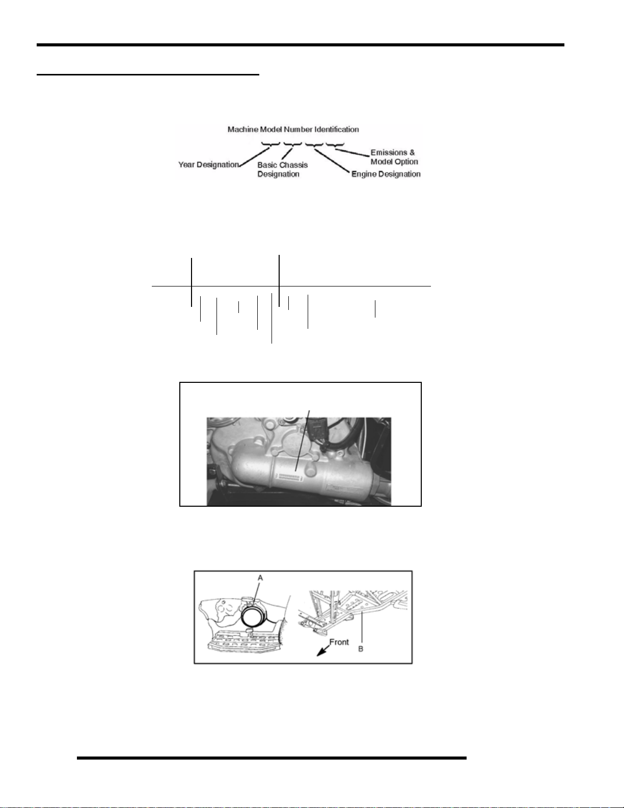
MODEL NUMBER INFORMATION
Model Number
The machine model number must be used with any correspondence regarding warranty or service.
A07 MN 50 AU
Engine Designation Numbers
EH50PLE - Single Cylinder, Liquid Cooled,4 Stroke, Electric Start
V ehicle Identification Number (VIN)
World
Mfg. ID
1 2 3 4 5 6 7 8 9 10 11 12 13 14 15 16 17
4 X A M N 5 0 A * 7 P 0 0 0 0 0 0
Vehicle Descriptor
}
Vehicle Identifier
Body Style
Transmission I.d. Location
Engine And Machine Serial Numbers
The machine model number and serial number are important for vehicle identification. Be sure to refer to the engine model number
and serial number whenever corresponding about an engine. This information can be found on the sticker applied to the top side
of the crankcase (A). An additional number is stamped on the side of the crankcase beneath the cylinder coolant elbow.
Engine
Powertrain
Emissions
The transmission I.D.number is located on top of
the transmission snorkel, right side of machine.
Model
Year
Check Digit
Plant No
Individual Serial Number
* This could be either
a number or a letter
The machine serial number is stamped on the lower left side of the frame tube (B).
1.2
Publications
GENERAL INFORMATION
Table 1-1: Publications
Year Model Model No.
A07MN50A
2007 Sportsman 500 EFI
2007 Sportsman X2 500 EFI
2007 Sportsman 450 EFI A07MH46A 9920629 9920557 N/A
2007
Sportsman X2 500 EFI
Quadricycle
A07MH50A (Standard)
A07MH50F (Standard Intl’)
A07TN50A
A07TH50A (Standard)
A07MH46E 9920650 9920899 N/A
(Deluxe)
(Deluxe)
Owner's
Manual PN
9920364 9920365 N/A
9920632 9920902 N/A
Parts
Manual PN
Paint Codes
Table 1-2: Paint Codes
PAINTED PART
Sportsman Frame Black 9440 P-067
COLOR
DESCRIPTION
DITZLER
NUMBER
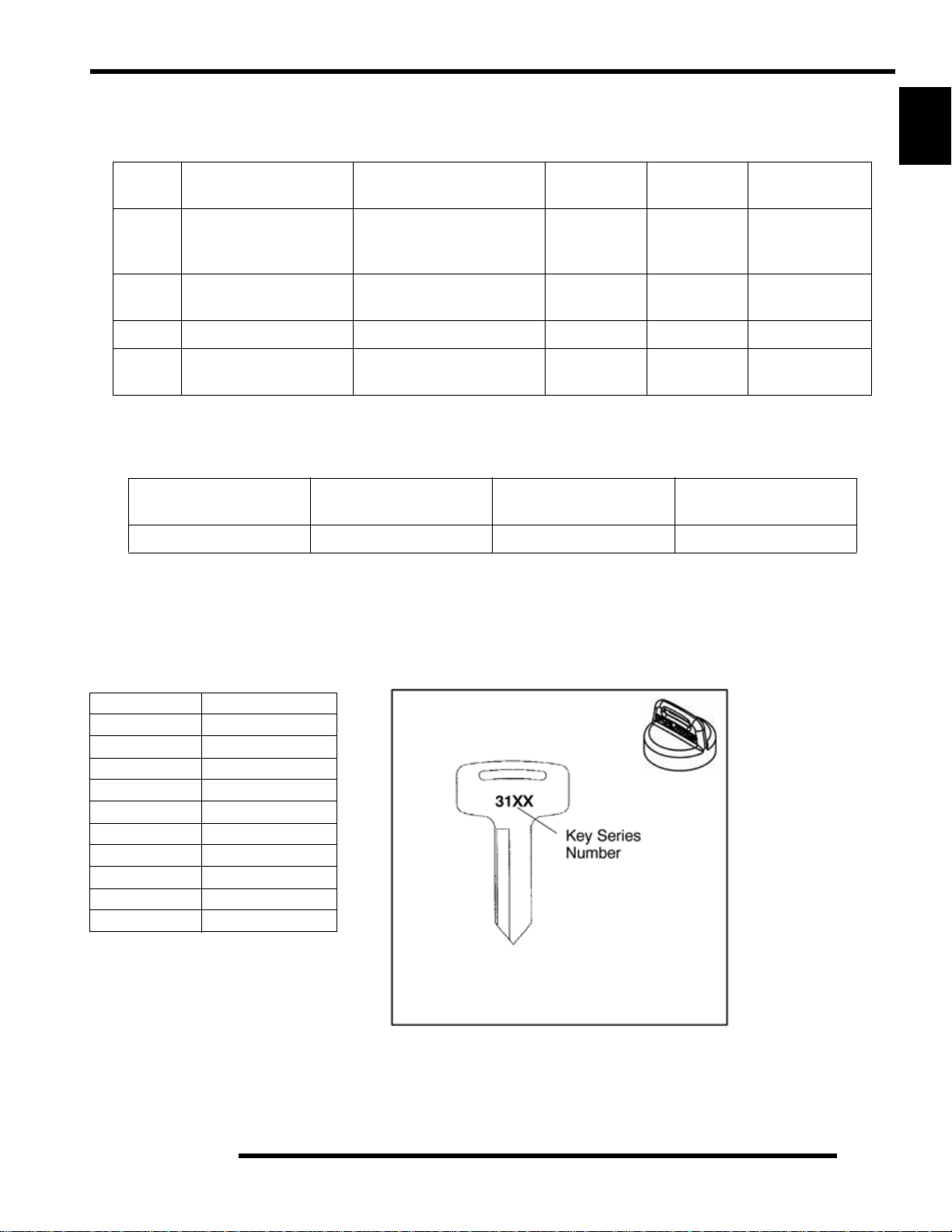
Replacement Keys
1
Parts
Micro Fiche PN
POLARIS
NUMBER
Replacement keys can be made from the original key (Phoenix excluded). To identify which series the key is, take the first two digits
on the original key and refer to the chart to the right for the proper part number. Should both keys become lost, ignition switch
replacement is required.
Table 1-3: Key Numbers
Series # Part Number
20 4010278
21 4010278
22 4010321
23 4010321
27 4010321
28 4010321
31 4110141
32 4110148
67 4010278
68 4010278
Key Cover
PN 5433534
1.3
GENERAL INFORMATION
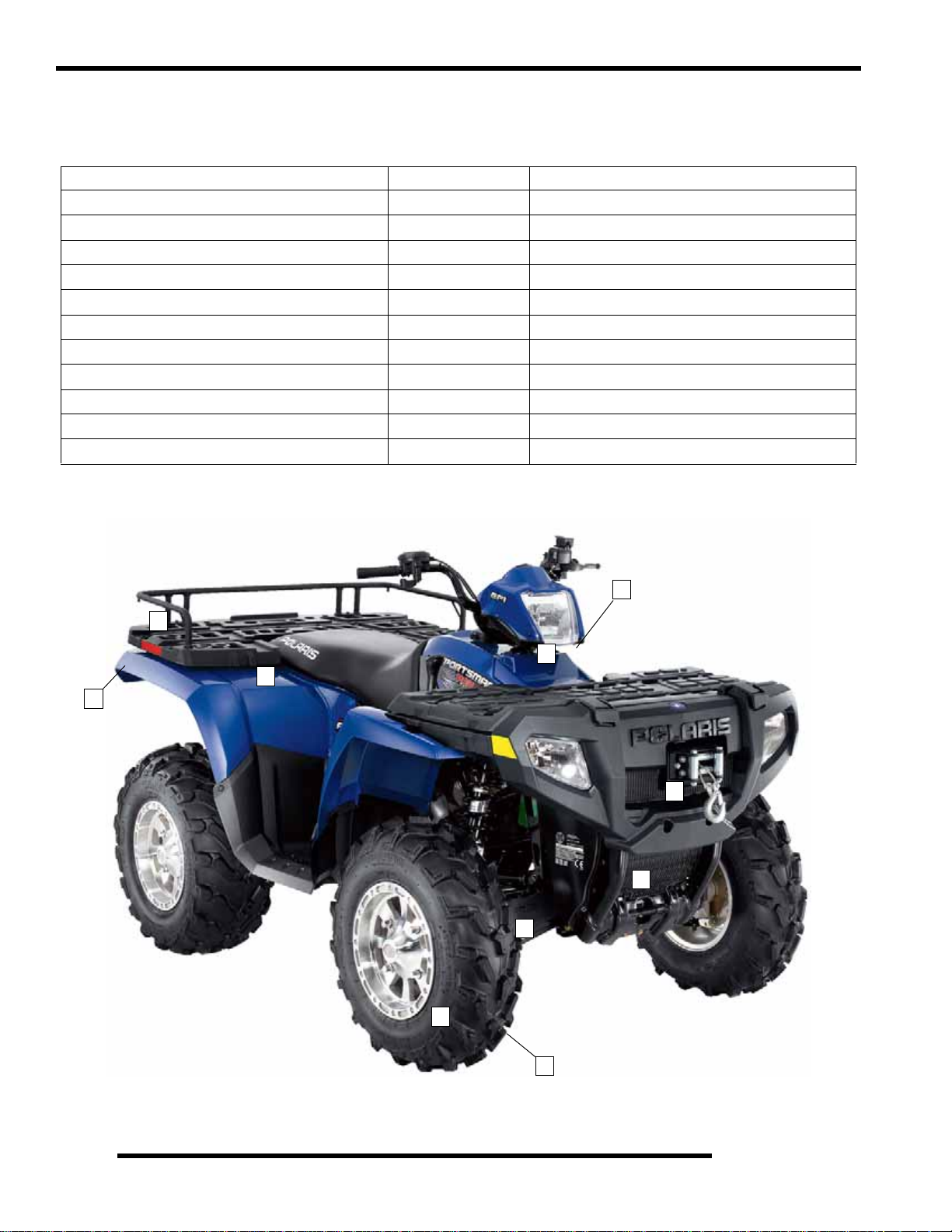
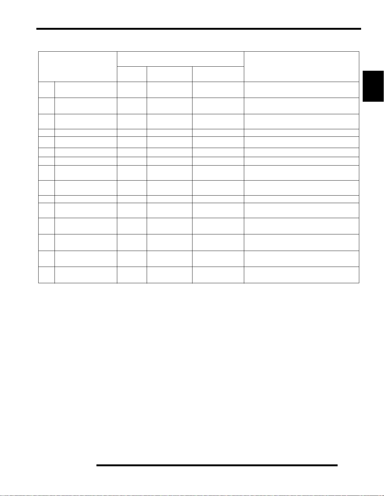
Sportsman ‘Deluxe’ and ‘Standard’ Model Component Comparison
For Model Year 2007, a Sportsman ‘Deluxe’ and ‘Standard’ model were offered. Use the following table as a guide:
SPORTSMAN ‘DELUXE’ MODEL Item Location SPORTSMAN ‘STANDARD’ MODEL
Winch 1 No Winch
PXT Tires 2 Titan Tires
PVT w/EBS 3 Non-EBS (X2 excluded)
Rear Work Lights 4 No Work Lights
Front Drive w/ Active Descent Control (ADC) 5 No Active Descent Control (ADC)
Speed Sensor Wiring for ADC 6 No Sensor Wiring Change
Rear Rack Extension 7 No Rack Extension
Cast Aluminum Wheels 8 Steel Wheels
Single Exhaust 9 Single Exhaust
Wire Harness w/ Active Descent Control (ADC) 10 Standard Wire Harness
PDM w/ Active Descent Control (ADC) 10 Standard PDM
3
7
10
9
4
1
5
6
Deluxe Model Pictured
8
1.4
2
GENERAL INFORMATION
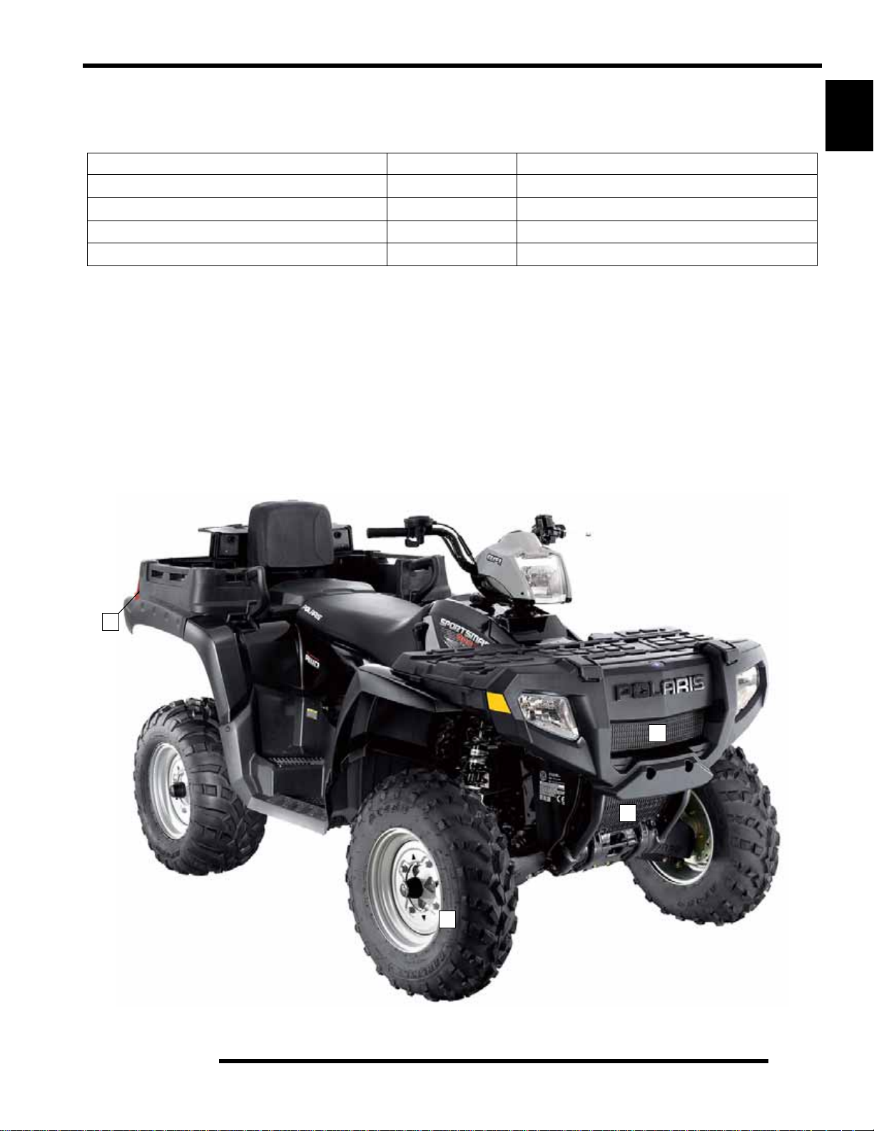
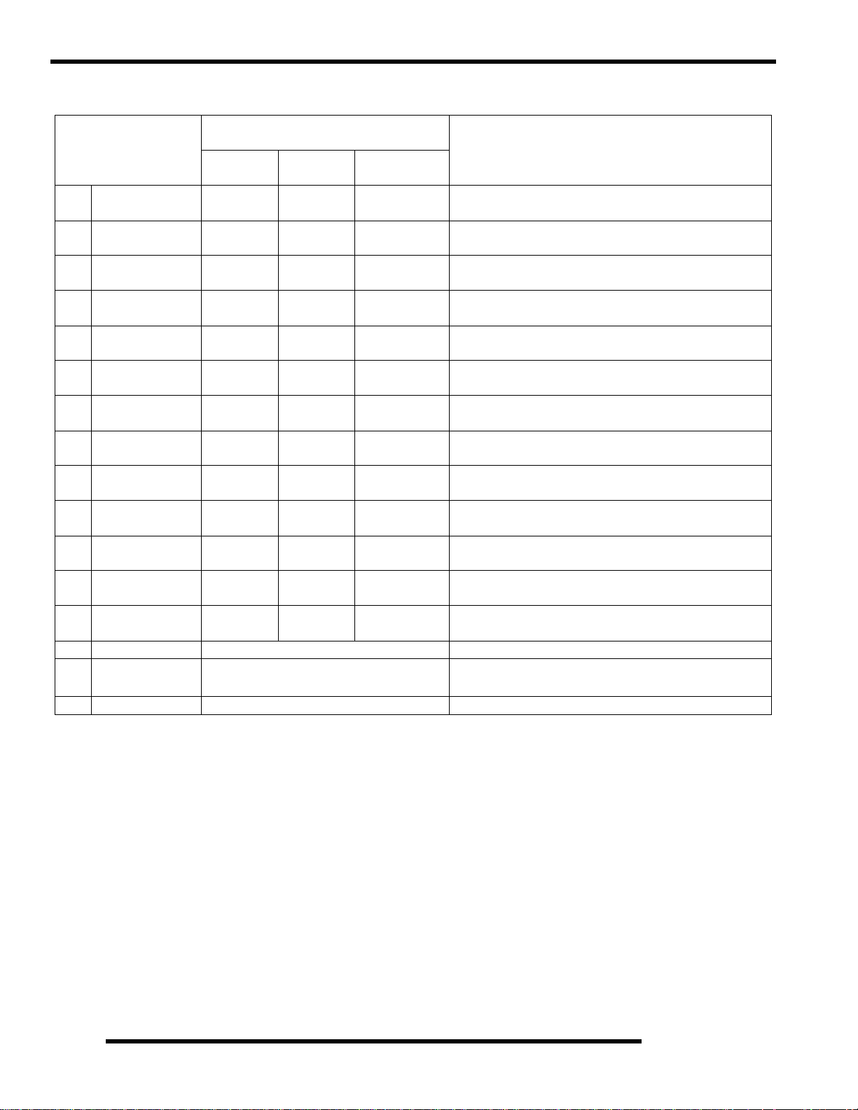
Sportsman X2 ‘Deluxe’ and ‘Standard’ Model Component Comparison
For Model Year 2007, an X2 ‘Deluxe’ and ‘Standard’ model were offered. Use the following table as a guide:
X2 ‘DELUXE’ MODEL Item Location X2 ‘STANDARD’ MODEL
Winch 1 No Winch
Rear Work Lights 2 No Work Lights
Front Drive w/ Active Descent Control (ADC) 3 No Active Descent Control (ADC)
Cast Aluminum Wheels 4 Steel Wheels
1
2
1
3
Standard Model Pictured
4
1.5
GENERAL INFORMATION
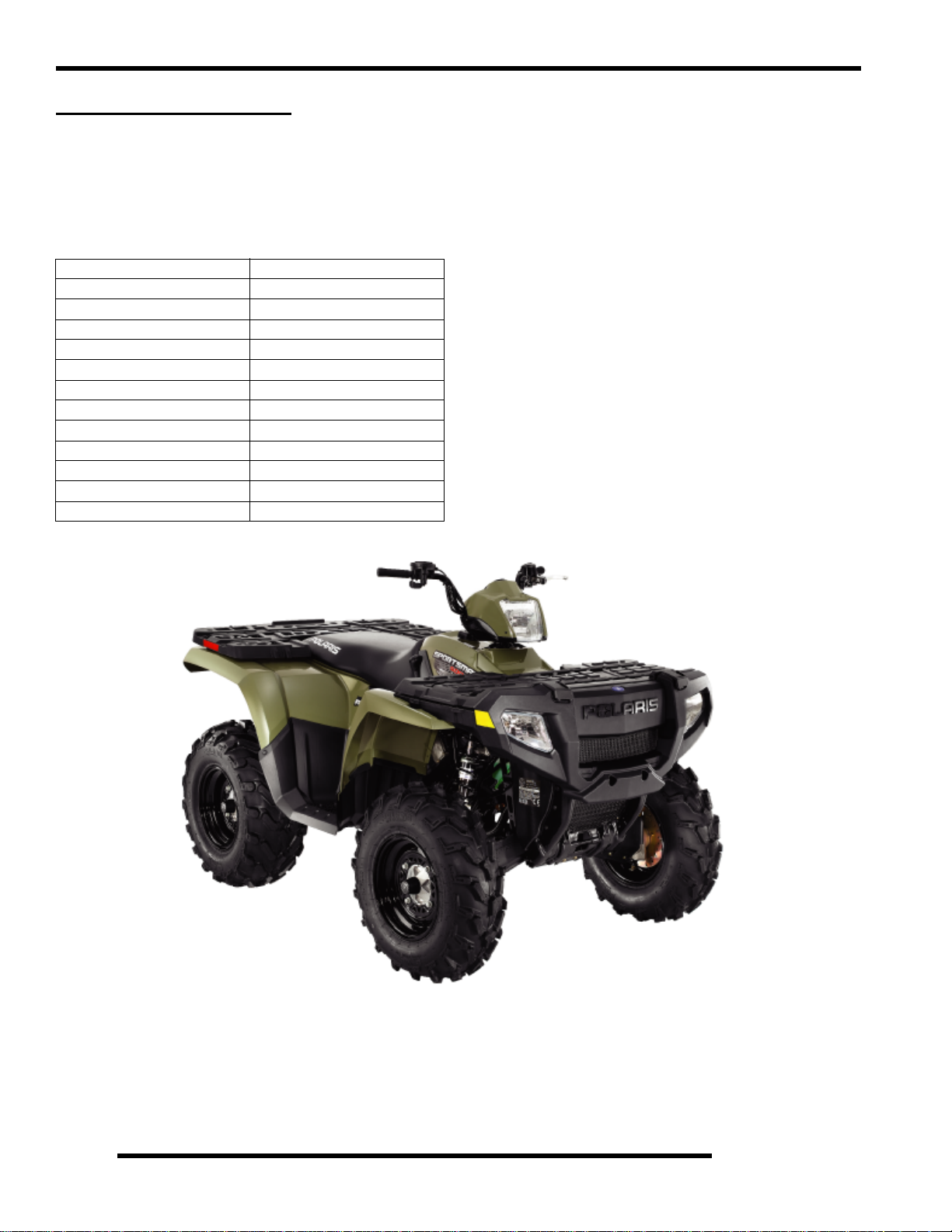
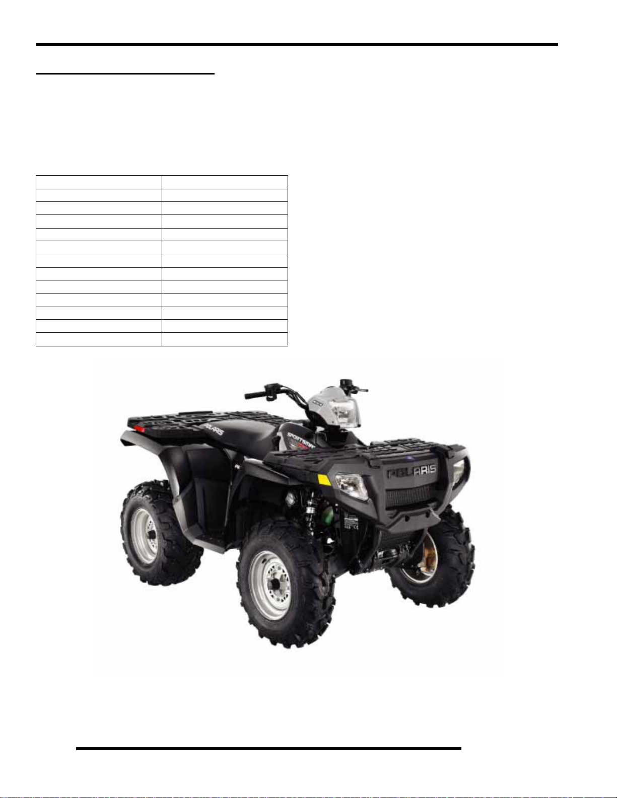
2007 SPORTSMAN 450
Model Number: A07MH46AA, AZ
Engine Model: EH46PLE
Table 1-4: Sportsman 450 General
Specifications
Category Dimension / Capacity
Length 83 in./211 cm
Width 48 in./122 cm
Height 48 in./122 cm
Wheel Base 50.5 in./128.3 cm
Ground Clearance 11 in./27.94 cm
Dry Weight 715 lbs./324 kg
Gross Vehicle Weight 1210 lbs./549 kg
Front Rack Capacity 90 lbs./40.8 kg
Rear Rack Capacity 180 lbs./81.6 kg
Towing Capacity 1225 lbs./555.6 kg
Body Style Spirit
Hitch Tongue Capacity 120 lbs./54.4 kg
1.6
GENERAL INFORMATION
Table 1-5: Sportsman 450
ENGINE
Platform Fuji Single Cylinder
Engine Model Number EH46PL E010
Engine Displacement 455cc
Number of Cylinders 1
Bore & Stroke (mm) 87.9 x 75 mm
Compression Ratio 9.8:1
Compression Pressure 50-90 psi
Engine Idle Speed
Engine Max Operating Rpm
Cooling System / Capacity Liquid - 2.25 qt / 2.1 ltr
Overheat Warning HOT on Instrument Cluster
Lubrication Pressurized Dry Sump
Oil Requirements / Capacity Polaris 0W-40 2 qt. / 1.9 ltr
Exhaust System Single Pipe USFS Approved
Fuel System
Carburetor Mikuni BST 34mm
Main Jet 167.5
Pilot Jet 42.5
Jet Needle / Clip Position 4IB33 - 3
Needle Jet P-6M (829)
Pilot Screw 2 3/4 Turns Out (initial)
Pilot Air Jet 1.3
Float Height
Fuel Delivery Fuel Pump
Fuel Capacity / Requirement 4.25 gal US / 19.9 liters
Electrical
Alternator Output 260 w @ 3000 RPM
Voltage Regulator 3-phase - PDM
Lights : Pod 50 watts
Grill 2 x 37 watts
Brake 26.9 watts
Tail 8.26 watts
Worklight 13 watts
Indicator 1 watt
Operating RPM
Ignition System DC/CDI Ignition
Ignition Timing
Spark plug / Gap BKR6E / .035 in. / 0.9 mm
Battery / Amp Hr Maintenance-Free / 12 Amp Hr.
Circuit Protection Solid State - PDM
Starting Electric / Recoil
Instrument Cluster Analog Speedo w/ LCD
6000 RPM
30
W/Compression Release
1100
50 RPM
6000 Rpm
13mm
87 Octane (minimum)
200 Rpm
1 (.51 0.40")
or 89 Oxygenated
°2° BTDC @ 5000 RPM
Table 1-6: Sportsman 450
Drivetrain
Transmission Type Drumshift - H/L/N/R/P
Transmission Capacity 32 oz. / 948 ml
Front Gearcase Capacity 8.97 oz. / 265 ml
Gear Ratio : Low
Rev
High
Front Drive
Clutch Type PVT Non-EBS
Belt 3211077
23.91:1
16.30:1
10.49:1
3.82:1
Steering / Suspension
Front Suspension / Shock A-arm / MacPherson Strut
Front Travel 8.2 in. / 20.8 cm
Rear Suspension / Shock Progressive Rate Independent -
w/ 2
" Coil-over shock
Rear Travel 9.5 in. / 24.13 cm
Ground Clearance 11 in. / 27.94 cm
Shock Preload Adjustment
Front / Rear
Turning Radius 65 in./165.10 cm unloaded
Toe Out 0-1/16 in / .0 - .159 mm
Front -Non Adjustable.
Rear - Ratchet Style- Std.
Wheels / Brakes
Wheel / Tire Size / Pattern - Front Steel 25x8 - 12 / 4-156
Wheel / Tire Size / Pattern - Rear Steel 25x11 - 12 / 4-156
Recommended Air Pressure Front & Rear - 5 psi
Brake - Front Dual Hydraulic Disc
Brake - Rear Single Hydraulic Disc
Brake Fluid DOT - approved only
Table 1-7: Sportsman 450 Jetting
AMBIENT TEMPERATURE
M e t e r s
(Feet)
Altitude
0-1800
(0-6000)
1800-3700
(6000-12000)
Below 40
Below 5 ° C
° F
+40 to +80 ° F
+5 to +28 ° C
175 167.5
162.5 157.5
Table 1-8: Sportsman 450 Clutching
M e t e r s
(Feet)
Altitude
0-1800
(0-6000)
1800-3700
(6000-12000)
Shift
Weight
10 WH
(5630710)
20-40
(5631356)
Drive
Clutch
Spring
Blu/Grey
(7042202)
Blu/Grey
(7042202)
Driven
Clutch
Spring
Black
(7041782)
Black
(7041782)
Driven-
Helix
40
2+2
(5131446)
40
2+2
(5131446)
1
°
°
1.7
GENERAL INFORMATION
2007 SPORTSMAN 500 EFI
Model Number: A07MH50AX, AY, AZ, AQ / A07MN50AL, AF / A07MH50FC
(Standard Models) (Deluxe Models) (International)
Engine Model: EH50PLE
Table 1-9: Sportsman 500 EFI General
Specifications
Category Dimension / Capacity
Length 83 in./211 cm
Width 48 in./122 cm
Height 48 in./122 cm
Wheel Base 50.5 in./128.3 cm
Ground Clearance 11.25 in./28.6 cm
Dry Weight 715 lbs./324 kg
Gross Vehicle Weight 1200 lbs./544 kg
Front Rack Capacity 90 lbs./40.8 kg
Rear Box Capacity 180 lbs./81.6 kg
Towing Capacity 1225 lbs./555.6 kg
Body Style Spirit
Hitch Tongue Capacity 120 lbs./54.4 kg
1.8
GENERAL INFORMATION
Table 1-10: Sportsman 500 EFI
ENGINE
Platform Fuji Single Cylinder
Engine Model Number EH50PL E210
Engine Displacement 499cc
Number of Cylinders 1
Bore & Stroke (mm) 92 x 75 mm
Compression Ratio
Compression Pressure 50-90 psi W/Compression Release
Engine Idle Speed
Engine Max Operating Rpm
Cooling System / Capacity Liquid - 2.5 qt / 2.4 ltr
Overheat Warning HOT on Instrument Cluster
Lubrication Pressurized Dry Sump
Oil Requirements / Capacity Polaris 0W-40 2 qt. / 1.9 ltr
Exhaust System Single Pipe USFS Approved
Fuel System
Fuel System Electronic Fuel Injection (EFI)
Fuel Pump (in tank assembly) 25L per hr. at 39 psi
Fuel Filter(s) 10 micron in-line
30 micron in tank Fuel Injector(s) Visteon
EFI Controller Visteon VP5U1U-12A650-AA
Fuel Capacity / Requirement 6 gal US / 22.7 liters
Electrical
Alternator Output 350 w @ 6000 RPM
Lights : Pod 50 watts
Grill 2 x 37 watts
Brake 2 x 8.26 watts
Tail 2 x 26.9 watts
Worklight 2 x 13 watts
Indicator 1 watt
Operating RPM
Ignition System DC/CDI Ignition
Ignition Timing
Spark plug / Gap BKR6E / .035 in. / 0.9 mm
Battery / Amp Hr Lead Acid / 30 Amp Hr.
Circuit Breakers Fan 12 amp / Switched Power 10
Starting Electric / Recoil
Instrument Cluster Analog Speedo w/ LCD
6000 RPM
13
amp / Fuel Pump 10 amp / ECU
15 amp / Ignition Coil 10 amp /
Accessory Power 10 amp /
10.2:1
1100
200 RPM
6000 Rpm
87 Octane (minimum)
200 Rpm
(not replaceable)
or 89 Oxygenated
° BTDC @ 1150 RPM
Lights 20 Amp
Table 1-11: Sportsman 500 EFI
Drivetrain
Transmission Type Drumshift - H/L/N/R/P
Transmission Capacity 32 oz. / 948 ml
Front Gearcase Capacity- CH 8.97 / 265 ml
Front Gearcase Capacity- ADC 9.3 / 275 ml
Gear Ratio : Low
Rev
High
Front Drive
Clutch Type PVT (Standard Models)
PVT w/EBS (Deluxe Models)
Belt 3211113 EBS
23.91:1
21.74:1
10.57:1
3.82:1
3211077 Non-EBS
Steering / Suspension
Front Suspension / Shock A-arm / MacPherson Strut
Front Travel 8.2 in. / 20.8 cm
Rear Suspension / Shock Progressive Rate Independent -
Coil - over shock
Rear Travel 9.5 in. / 24.13 cm
Ground Clearance 11 in. / 27.94 cm
Shock Preload Adjustment
Front / Rear
Turning Radius 65 in./165.10 cm unloaded
Toe Out 0-1/16 in / .0 - .159 mm
Front -Non Adjustable.
Rear - Ratchet Style- Std.
Wheels / Brakes
Wheel/Tire Size / Pattern - Front 26 x 8 - 12 / 4-156
Wheel/Tire Size / Pattern - Rear 26 x 11 - 12 / 4-156
Recommended Air Pressure Front & Rear - 5 psi
Brake - Front Dual Hydraulic Disc
Brake - Rear Single Hydraulic Disc
Brake Fluid DOT - approved only
Table 1-12: Sportsman 500 EFI Clutching
Altitude Shift
M e t e r s
(Feet)
0-1800
(0-6000)
1800-3700
(6000-12000)
Weight
10 WH
(5630710)
10 RH
(5630709)
Drive
Clutch
Spring
Blu/Green
(7041157)
Blu/Green
(7041157)
Driven
Clutch
Spring
White/Yel
(7041635)
White/Yel
(7041635)
Helix*
*No
Adjustment
EBS
(5131674)
EBS
(5131674)
1
1.9
GENERAL INFORMATION
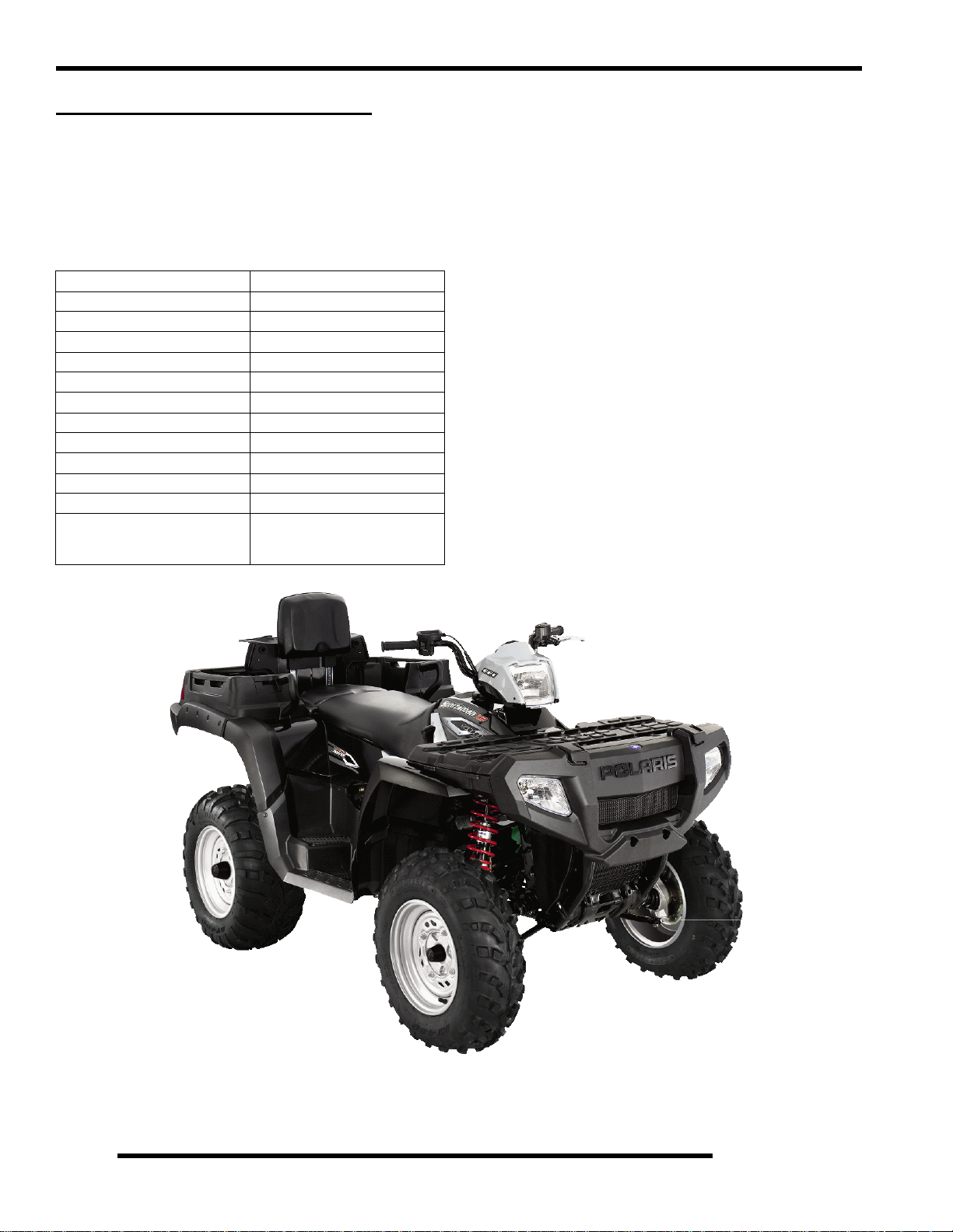
2007 SPORTSMAN X-2 500 EFI
Model Number: A07TH50AU, AZ, AQ / A07TN50AF / A07TH50EA
(Standard Models) (Deluxe Model) (Intl’ Quadricycle)
Engine Model: EH50PLE
Table 1-13: Sportsman X-2 500 EFI General
Specifications
Category Dimension / Capacity
Length 93 in./236 cm
Width 48 in./122 cm
Height 48 in./122 cm
Wheel Base 57 in./145 cm
Ground Clearance 11 in./28 cm
Dry Weight 798 lbs./362 kg
Gross Vehicle Weight 1500 lbs./680 kg
Front Rack Capacity 90 lbs./40.8 kg
Rear Box Capacity 400 lbs./81.6 kg
Towing Capacity 1225 lbs./555.6 kg
Body Style Spirit
Hitch Tongue Capacity 120 lbs./54.4 kg
Rear box capacity and tongue weight
not to exceed 400 lbs./181kg
1.10
GENERAL INFORMATION
Table 1-14: Sportsman X2 500 EFI
ENGINE
Platform Fuji Single Cylinder
Engine Model Number EH50PL E210
Engine Displacement 499cc
Number of Cylinders 1
Bore & Stroke (mm) 92 x 75 mm
Compression Ratio 10.2:1
Compression Pressure 60-90 psi
Engine Idle Speed
Engine Max Operating Rpm
Cooling System / Capacity Liquid - 2.5 qt / 2.4 ltr
Overheat Warning HOT on Instrument Cluster
Lubrication Pressurized Dry Sump
Oil Requirements / Capacity Polaris 0W-40 2 qt. / 1.9 ltr
Exhaust System Single Pipe USFS Approved
Fuel System
Fuel System Electronic Fuel Injection (EFI)
Fuel Pump (in tank assembly) 25L per hr. at 39 psi
Fuel Filter(s) 10 micron in-line
30 micron in tank Fuel Injector(s) Visteon
EFI Controller Visteon VP5U1U-12A650-AA
Fuel Capacity / Requirement 6 gal US / 22.7 liters
Electrical
Alternator Output 350 w @ 6000 RPM
Lights : Pod 50 watts
Grill 2 x 37 watts
Brake 2 x 8.26 watts
Tail 2 x 26.9 watts
Worklight 2 x 13 watts
Indicator 1 watt
Operating RPM
Ignition System DC/CDI Ignition
Ignition Timing
Spark plug / Gap BKR6E / .035 in. / 0.9 mm
Battery / Amp Hr Lead Acid / 30 Amp Hr.
Circuit Breakers Fan 12 amp / Switched Power 10
Starting Electric / Recoil
Instrument Cluster Analog Speedo w/ LCD
6000 RPM
10
amp / Fuel Pump 10 amp / ECU
15 amp / Ignition Coil 10 amp /
W/Compression Release
1150
50 RPM
6000 Rpm
87 Octane (minimum)
200 Rpm
(not replaceable)
or 89 Oxygenated
° BTDC @ 1150 RPM
Accessory Power 10 amp /
Lights 20 Amp
Table 1-15: Sportsman X2 500 EFI
Drivetrain
Transmission Type Drumshift - H/L/N/Rev/Park
Transmission Capacity 32 oz. / 948 ml
Front Gearcase Capacity- CH 8.97 / 265 ml
Front Gearcase Capacity- ADC 9.3 / 275 ml
Gear Ratio : Low
Rev
High
Front Drive
Clutch Type PVT w/EBS
Belt 3211113
23.91:1
21.74:1
10.57:1
3.82:1
Steering / Suspension
Front Suspension / Shock A-arm / MacPherson Strut
Front Travel 8.2 in. / 20.8 cm
Rear Suspension / Shock Progressive Rate Independent -
Coil - over shock
Rear Travel 8.75 in. / 22.2 cm
Ground Clearance 11 in. / 28 cm
Shock Preload Adjustment
Front / Rear
Turning Radius 82 in./208 cm unlocked
Toe Out 0-1/16 in / .0 - .159 mm
Front -Non Adjustable.
Rear - Ratchet Style- Std.
Wheels / Brakes
Wheel Size / Pattern - Front Steel 12x6 / 4-156
Wheel Size / Pattern - Rear Steel 12x8 / 4-156
Front Tire Size 25x8-12
Rear Tire Size 25x11-12
Recommended Air Pressure Front & Rear - 5 psi
Brake - Front Dual Hydraulic Disc
Brake - Rear Dual Hydraulic Disc
Table 1-16: Sportsman X2 500 EFI
Altitude Shift
M e t e r s
(Feet)
0-1800
(0-6000)
1800-3700
(6000-12000)
Weight
10 WH
(5630710)
10 RH
(5630709)
Drive
Clutch
Spring
Blu/Green
(7041157)
Blu/Green
(7041157)
Driven
Clutch
Spring
White/Yel
(7041635)
White/Yel
(7041635)
Helix*
*No
Adjustment
EBS
(5131674)
EBS
(5131674)
1
1.11
GENERAL INFORMATION
MISC. NUMBERS/CHARTS
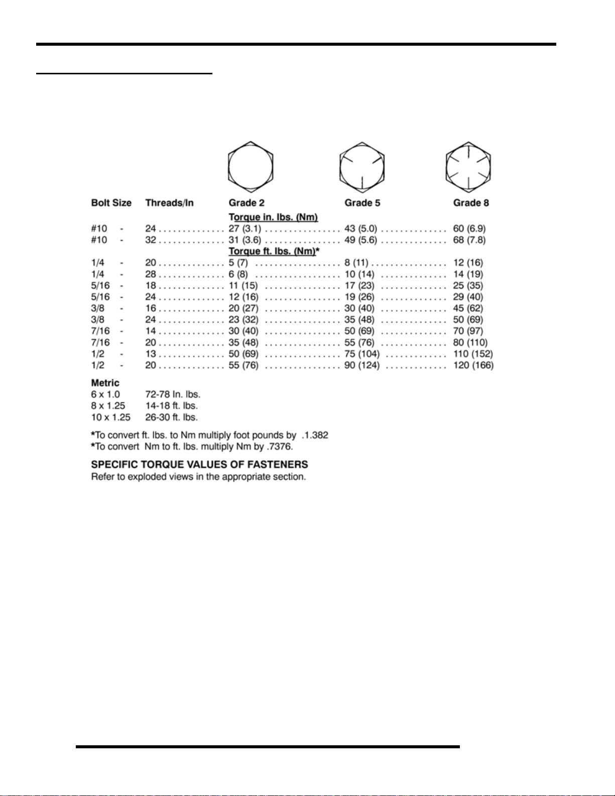
Standard Torque Specifications
The following torque specifications are to be used as a general guideline. There are exceptions in the steering, suspension, and engine
areas. Always consult the exploded views in each manual section for torque values of fasteners before using standard torque.
1.12
GENERAL INFORMATION
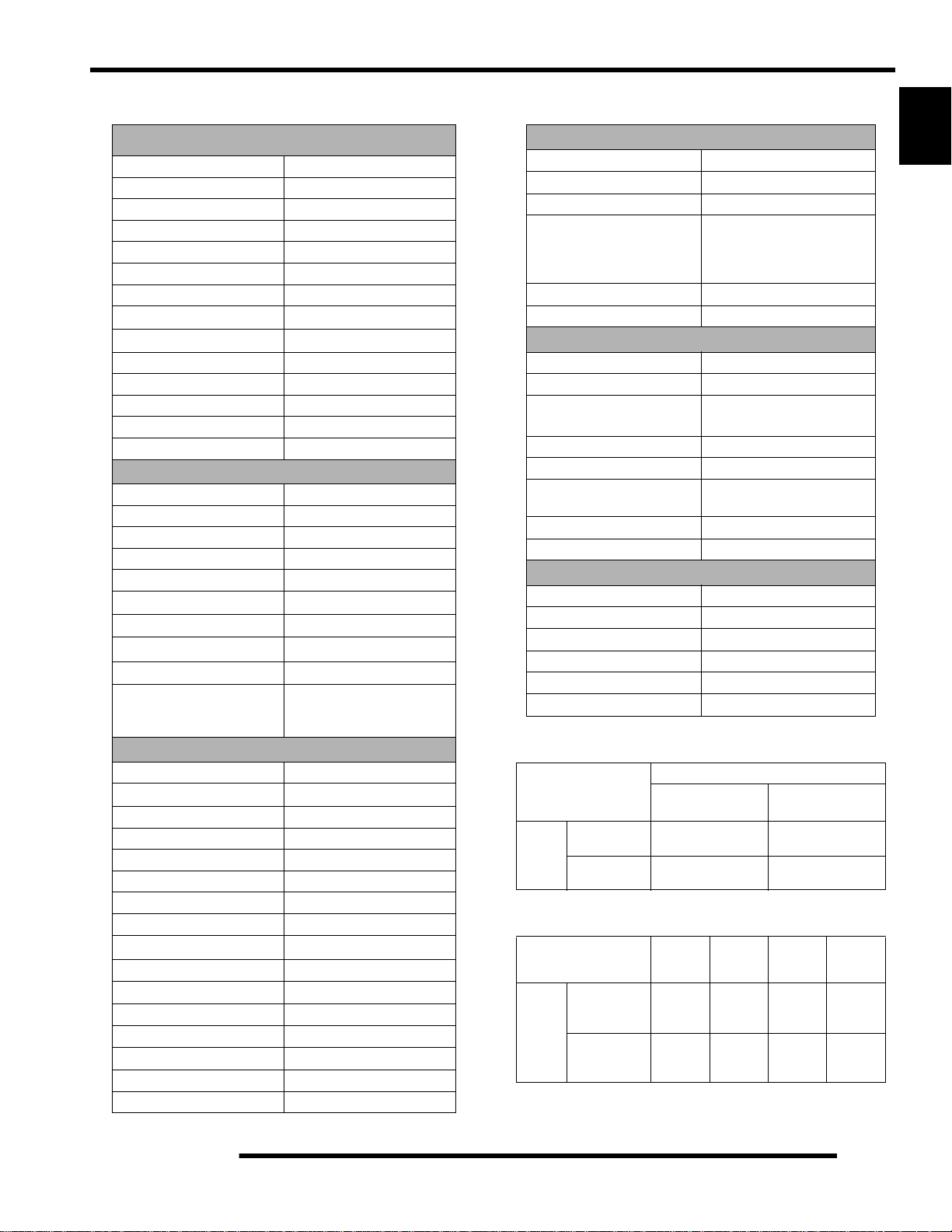
SAE Tap Drill Sizes
Thread Size/ Drill Size Thread Size / Drill Size
#0-80 3/64 1/2-13 27/64
#1-64 53 1/2-20 29/64
#1-72 53 9/16-12 31/64
#2-56 51 9/16-18 33/64
#2-64 50 5/8-11 17/32
#3-48 5/64 5/8-18 37/64
#3-56 45 3/4-10 21/32
#4-40 43 3/4-16 11/16
#4-48 42 7/8-9 49/64
#5-40 38 7/8-14 13/16
#5-44 37 1-8 7/8
#6-32 36 1-12 59/64
#6-40 33 1 1/8-7 63/64
#8-32 29 1 1/8-12 1 3/64
#8-36 29 1 1/4-7 1 7/64
#10-24 24 1 1/4-12 1 11/64
#10-32 21 1 1/2-6 1 11/32
#12-24 17 1 1/2-12 1 27/64
#12-28 4.6mm 1 3/4-5 1 9/16
1/4-20 7 1 3/4-12 1 43/64
1/4-28 3 2-4 1/2 1 25/32
5/16-18 F 2-12 1 59/64
5/16-24 I 2 1/4-4 1/2 2 1/32
3/8-16 O 2 1/2-4 2 1/4
3/8-24 Q 2 3/4-4 2 1/2
7/16-14 U 3-4 2 3/4
7/16-20 25/64
Metric Tap Drill Sizes
Tap Size Drill Size
3x.50 #39 0.0995 3/32
3x.60 3/32 0.0937 3/32
4x.70 #30 0.1285 1/8
4x.75 1/8 0.125 1/8
5x.80 #19 0.166 11/64
5x.90 #20 0.161 5/32
6x1.00 #9 0.196 13/64
7x1.00 16/64 0.234 15/64
8x1.00 J 0.277 9/32
8x1.25 17/64 0.265 17/64
9x1.00 5/16 0.3125 5/16
9x1.25 5/16 0.3125 5/16
10x1.25 11/32 0.3437 11/32
10x1.50 R 0.339 11/32
11x1.50 3/8 0.375 3/8
12x1.50 13/32 0.406 13/32
12x1.75 13/32 0.406 13/32
Decimal
Equivalent
Nearest
Fraction
Decimal Equivalents
1/64 . . . . . . . . . . .. . . . . . . .0156
1/32 . . . . . . .. . . . . . . .0312 . . 1 mm= .0394"
3/64 . . . . . . . . . . .. . . . . . . .0469
1/16 . . . . . . .. . . . . . . .0625
5/64 . . . . . . . . . . .. . . . . . . .0781 . . 2 mm = .0787"
3/32 . . . . . . .. . . . . . . .0938
7/64 . . . . . . . . . . .. . . . . . . .1094 . . 3 mm =.1181"
1/8 . . . . . . . . .1250
9/64 . . . . . . . . . . .. . . . . . . .1406
5/32 . . . . . . .. . . . . . . .1563 . . 4 mm = .1575"
11/64 . . . . . . . . . . .. . . . . . . .1719
3/16 . . . . . . .. . . . . . . .1875 . . 5mm= .1969"
13/64 . . . . . . . . . . .. . . . . . . .2031
7/32 . . . . . . .. . . . . . . .2188
15/64 . . . . . . . . . . .. . . . . . . .2344 . . 6 mm = .2362"
1/4 . . . . . . . . .25
17/64 . . . . . . . . . . .. . . . . . . .2656 . . 7 mm = .2756"
9/32 . . . . . . .. . . . . . . .2813
19/64 . . . . . . . . . . .. . . . . . . .2969
5/16 . . . . . . .. . . . . . . .3125 . . 8mm= .3150"
21/64 . . . . . . . . . . .. . . . . . . .3281
11/32 . . . . . .. . . . . . . .3438 . . 9 mm = .3543"
23/64 . . . . . . . . . . .. . . . . . . .3594
3/8 . . . . . . . . .375
25/64 . . . . . . . . . . .. . . . . . . .3906 . . 10 mm = .3937"
13/32 . . . . . .. . . . . . . .4063
27/64 . . . . . . . . . . .. . . . . . . .4219 . . 11 mm =.4331"
7/16 . . . . . . .. . . . . . . .4375
29/64 . . . . . . . . . . .. . . . . . . .4531
15/32 . . . . . .. . . . . . . .4688 . . 12 mm = .4724"
31/64 . . . . . . . . . . .. . . . . . . .4844
1/2 . . . . . . . . .5 . . . . . . . . . . . 13mm = .5118"
33/64 . . . . . . . . . . .. . . . . . . .5156
17/32 . . . . . .. . . . . . . .5313
35/64 . . . . . . . . . . .. . . . . . . .5469 . . 14 mm = .5512"
9/16 . . . . . . .. . . . . . . .5625
37/64 . . . . . . . . . . .. . . . . . . .5781 . . 15 mm = .5906"
19/32 . . . . . .. . . . . . . .5938
39/64 . . . . . . . . . . .. . . . . . . .6094
5/8 . . . . . . . . .625 . . . . . . . . . 16mm=. 6299"
41/64 . . . . . . . . . . .. . . . . . . .6406
21/32 . . . . . .. . . . . . . .6563 . . 17 mm =.6693"
43/64 . . . . . . . . . . .. . . . . . . .6719
11/16 . . . . . .. . . . . . . .6875
45/64 . . . . . . . . . . .. . . . . . . .7031 . . 18 mm = .7087"
23/32 . . . . . .. . . . . . . .7188
47/64 . . . . . . . . . . .. . . . . . . .7344 . . 19 mm = .7480"
3/4 . . . . . . . . .75
49/64 . . . . . . . . . . .. . . . . . . .7656
25/32 . . . . . .. . . . . . . .7813 . . 20 mm = .7874"
51/64 . . . . . . . . . . .. . . . . . . .7969
13/16 . . . . . .. . . . . . . .8125 . . 21 mm =.8268"
53/64 . . . . . . . . . . .
27/32 . . . . . .. . . . . . . .8438
55/64 . . . . . . . . . . .. . . . . . . .8594 . . 22 mm = .8661"
7/8 . . . . . . . . .875
57/64 . . . . . . . . . . .. . . . . . . .8906 . . 23 mm = .9055"
29/32 . . . . . .. . . . . . . .9063
59/64 . . . . . . . . . . .. . . . . . . .9219
15/16 . . . . . .. . . . . . . .9375 . . 24 mm = .9449"
61/64 . . . . . . . . . . .. . . . . . . .9531
31/32 . . . . . .. . . . . . . .9688 . . 25 mm = .9843"
63/64 . . . . . . . . . . .. . . . . . . .9844
1. . . . . . . . . . 1.0
. . . . . . . .8281
1
1.13

GENERAL INFORMATION
Conversion Table
Unit of Measure Multiplied by Converts to
ft. lbs. x 12 = in. lbs.
in. lbs. x .0833 = ft. lbs.
ft. lbs. x 1.356 = Nm
in. lbs. x .0115 = kg-m
Nm x .7376 = ft. lbs.
kg-m x 7.233 = ft. lbs.
kg-m x 86.796 = in. lbs.
kg-m x 10 = Nm
in. x 25.4 =mm
mm x .03937 = in.
in. x 2.54 = cm
mile (mi.) x 1.6 = km
km x .6214 = mile (mi.)
Ounces (oz.) x 28.35 = Grams (g)
Fluid Ounces (fl. oz.) x 29.57 = Cubic Centimeters (cc)
Cubic Centimeters (cc) x .03381 = Fluid Ounces (fl. oz.)
Grams (g) x 0.035 = Ounces (oz.)
lb. x .454 = kg
kg x 2.2046 = lb.
Cubic inches (cu. in) x 16.387 = Cubic centimeters (cc)
Cubic centimeters (cc) x 0.061 = Cubic inches (cu. in)
Imperial pints (Imp pt.) x 0.568 = Liters (l)
Liters (l) x 1.76 = Imperial pints (Imp pt.)
Imperial quarts (Imp qt.) x 1.137 = Liters (l)
Liters (l) x 0.88 = Imperial quarts (Imp qt.)
Imperial quarts (Imp qt.) x 1.201 = US quarts (US qt.)
US quarts (US qt.) x 0.833 = Imperial quarts (Imp qt.)
US quarts (US qt.) x 0.946 = Liters (l)
Liters (l) x 1.057 = US quarts (US qt.)
US gallons (US gal) x 3.785 =Liters (l)
Liters (l) x 0.264 = US gallons (US gal)
Pounds - force per square inch (psi) x 6.895 = Kilopascals (kPa)
Kilopascals (kPa) x 0.145 = Pounds - force per square inch (psi)
Kilopascals (kPa) x 0.01 = Kilograms - force per square cm
Kilograms - force per square cm x 98.1 = Kilopascals (kPa)
(3.14)xR
2
x H (height) = Cylinder Volume
°C to °F: 9 (°C + 40) 5 - 40 = °F
°F to °C: 5 (°F + 40)
9 - 40 = °C
1.14

Glossary Of Terms
GENERAL INFORMATION
ABDC: After bottom dead center.
ACV: Alternating current voltage.
ADC: Active Descent Control.
Alternator: Electrical generator producing voltage alternating current.
ATDC: After top dead center.
BBDC: Before bottom dead center.
BDC: Bottom dead center.
BTDC: Before top dead center.
CC: Cubic centimeters.
Center Distance: Distance between center of crankshaft and center of driven clutch shaft.
Chain Pitch: Distance between chain link pins (No. 35 = 3/8, or 1 cm). Polaris measures chain length in number of pitches.
Crankshaft Run-Out: Run-out or "bend" of crankshaft measured with a dial indicator while crankshaft is supported between
centers on V blocks or resting in crankcase. Measure at various points especially at PTO.
DCV: Direct current voltage.
Electrical Open: Open circuit. An electrical circuit which isn't complete.
Electrical Short: Short circuit. An electrical circuit which is completed before the current reaches the intended load. (i.e. a bare
wire touching the chassis).
Engagement RPM: Engine RPM at which the drive clutch engages to make contact with the drive belt.
ft.: Foot/feet.
Ft. lb. / Foot Pound: A force of one pound at the end of a lever one foot in length, applied in a rotational direction.
g: Gram. Unit of weight in the metric system.
gal.: Gallon.
ID: Inside diameter.
in.: Inch/inches.
Inch Pound: In. lb. 12 in. lbs. = 1 ft. lb.
kg/cm: Kilograms per square centimeter.
kg-m: Kilogram meters.
Kilogram/meter: A force of one kilogram at the end of a lever one meter in length, applied in a rotational direction.
l or ltr: Liter.
Left Side: Always referred to based on normal operating position of the driver.
m: Meter/meters.
Mag: Magneto.
Magnetic Induction: As a conductor (coil) is moved through a m agnetic field, a voltage will be generated in the windings.
Mechanical energy is converted to electrical energy in the stator.
mi.: Mile/miles.
mm: Millimeter. Unit of length in the metric system. 1mm = approximately .040,.
Nm: Newton meters.
OD: Outside diameter.
Ohm: The unit of electrical resistance opposing current flow.
oz.: Ounce/ounces.
PDM: Power Distribution Module.
Piston Clearance: Total distance between piston and cylinder wall.
psi.: Pounds per square inch.
PTO: Power take off.
qt.: Quart/quarts.
RPM:
Revolutions per minute.
Regulator: Voltage regulator. Regulates battery charging system output at approx. 14.5 DCV as engine RPM increases.
Resistance: In the mechanical sense, friction or load. In the electrical sense, ohms. Both result in energy conversion to heat.
Right Side: Always referred to based on normal operating position of the driver.
RPM: Revolutions per minute.
Seized Piston: Galling of the sides of a piston. Usually there is a transfer of aluminum from the piston onto the cylin der wall.
Possible causes: 1) improper lubrication; 2) excessive temperatures; 3) insufficient piston clearance; 4) stuck piston rings.
Stator Plate: The plate mounted under the flywheel supporting the battery charging coils.
TDC: Top dead center. Piston's most outward travel from crankshaft.
Volt: The unit of measure for electrical pressure of electromotive force. Measured by a voltmeter in parallel with the circuit.
Watt: Unit of electrical power. Watts = amperes x volts.
WOT: Wide open throttle.
1
1.15

GENERAL INFORMATION
NOTES
1.16

MAINTENANCE
CHAPTER 2
MAINTENANCE
MAINTENANCE. . . . . . . . . . . . . . . . . . . . . . . . . . . . . . . . . . . . . . . . . . . . . . . . . . . . . . . . . 2.3
PERIODIC MAINTENANCE CHART . . . . . . . . . . . . . . . . . . . . . . . . . . . . . . . . . . . . . . . .2.3
MAINTENANCE CHART KEY . . . . . . . . . . . . . . . . . . . . . . . . . . . . . . . . . . . . . . . . . . . . .2.3
PERIODIC MAINTENANCE CHART . . . . . . . . . . . . . . . . . . . . . . . . . . . . . . . . . . . . . . . .2.4
LUBRICATION / FLUIDS. . . . . . . . . . . . . . . . . . . . . . . . . . . . . . . . . . . . . . . . . . . . . . . . . . 2.7
SPORTSMAN COMPONENT LOCATIONS. . . . . . . . . . . . . . . . . . . . . . . . . . . . . . . . . . .2 .7
SPORTSMAN X2 COMPONENT LOCATIONS . . . . . . . . . . . . . . . . . . . . . . . . . . . . . . . .2.8
POLARIS LUBRICANTS, MAINTENANCE AND SERVICE PRODUCTS . . . . . . . . . . . .2.9
POLARIS LUBRICANT SYMBOL IDENTIFICATION. . . . . . . . . . . . . . . . . . . . . . . . . . .2.10
PRE-RIDE / DAILY INSPECTION . . . . . . . . . . . . . . . . . . . . . . . . . . . . . . . . . . . . . . . . .2.10
LUBRICATION COMPONENTS. . . . . . . . . . . . . . . . . . . . . . . . . . . . . . . . . . . . . . . . . . .2.11
FRONT GEARCASE LUBRICATION. . . . . . . . . . . . . . . . . . . . . . . . . . . . . . . . . . . . . . .2.12
TRANSMISSION LUBRICATION. . . . . . . . . . . . . . . . . . . . . . . . . . . . . . . . . . . . . . . . . .2.13
ADC DIFFERENTIAL HYDRAULIC CIRCUIT FLUID CHANGE. . . . . . . . . . . . . . . . . . .2.14
VEHICLE INSPECTION. . . . . . . . . . . . . . . . . . . . . . . . . . . . . . . . . . . . . . . . . . . . . . . . . . 2.14
SHIFT LINK ROD INSPECTION. . . . . . . . . . . . . . . . . . . . . . . . . . . . . . . . . . . . . . . . . . .2.14
THROTTLE INSPECTION . . . . . . . . . . . . . . . . . . . . . . . . . . . . . . . . . . . . . . . . . . . . . . .2.15
THROTTLE CABLE / ELECTRONIC THROTTLE CONTROL ADJUSTMENT . . . . . . .2.15
FUEL SYSTEM. . . . . . . . . . . . . . . . . . . . . . . . . . . . . . . . . . . . . . . . . . . . . . . . . . . . . . . .2.16
FUEL LINES . . . . . . . . . . . . . . . . . . . . . . . . . . . . . . . . . . . . . . . . . . . . . . . . . . . . . . . . . .2.16
VENT LINES. . . . . . . . . . . . . . . . . . . . . . . . . . . . . . . . . . . . . . . . . . . . . . . . . . . . . . . . . .2.16
FUEL FILTER. . . . . . . . . . . . . . . . . . . . . . . . . . . . . . . . . . . . . . . . . . . . . . . . . . . . . . . . .2.17
COMPRESSION TEST. . . . . . . . . . . . . . . . . . . . . . . . . . . . . . . . . . . . . . . . . . . . . . . . . .2.17
ENGINE MOUNTS . . . . . . . . . . . . . . . . . . . . . . . . . . . . . . . . . . . . . . . . . . . . . . . . . . . . .2.17
SPARK PLUG. . . . . . . . . . . . . . . . . . . . . . . . . . . . . . . . . . . . . . . . . . . . . . . . . . . . . . . . .2.18
ACTIVE DESCENT CONTROL (ADC) RESERVOIR LEVEL. . . . . . . . . . . . . . . . . . . . . 2.18
BATTERY MAINTENANCE . . . . . . . . . . . . . . . . . . . . . . . . . . . . . . . . . . . . . . . . . . . . . .2.18
LIQUID COOLING SYSTEM OVERVIEW . . . . . . . . . . . . . . . . . . . . . . . . . . . . . . . . . . .2.19
COOLANT STRENGTH / TYPE. . . . . . . . . . . . . . . . . . . . . . . . . . . . . . . . . . . . . . . . . . .2.19
COOLING SYSTEM HOSES . . . . . . . . . . . . . . . . . . . . . . . . . . . . . . . . . . . . . . . . . . . . .2.19
RADIATOR/GRILL SCREEN . . . . . . . . . . . . . . . . . . . . . . . . . . . . . . . . . . . . . . . . . . . . .2.19
COOLING SYSTEM PRESSURE TEST. . . . . . . . . . . . . . . . . . . . . . . . . . . . . . . . . . . . .2.20
COOLANT LEVEL INSPECTION . . . . . . . . . . . . . . . . . . . . . . . . . . . . . . . . . . . . . . . . . .2.20
RADIATOR COOLANT LEVEL INSPECTION . . . . . . . . . . . . . . . . . . . . . . . . . . . . . . . .2.20
AIR FILTER/PRE-FILTER SERVICE . . . . . . . . . . . . . . . . . . . . . . . . . . . . . . . . . . . . . . .2.20
AIR BOX SEDIMENT TUBE. . . . . . . . . . . . . . . . . . . . . . . . . . . . . . . . . . . . . . . . . . . . . .2.21
BREATHER FILTER INSPECTION . . . . . . . . . . . . . . . . . . . . . . . . . . . . . . . . . . . . . . . .2.22
BREATHER HOSE. . . . . . . . . . . . . . . . . . . . . . . . . . . . . . . . . . . . . . . . . . . . . . . . . . . . .2.22
RECOIL HOUSING. . . . . . . . . . . . . . . . . . . . . . . . . . . . . . . . . . . . . . . . . . . . . . . . . . . . .2.22
ENGINE OIL LEVEL. . . . . . . . . . . . . . . . . . . . . . . . . . . . . . . . . . . . . . . . . . . . . . . . . . . .2.23
OIL AND FILTER CHANGE . . . . . . . . . . . . . . . . . . . . . . . . . . . . . . . . . . . . . . . . . . . . . .2.23
OIL PUMP PRIMING PROCEDURE . . . . . . . . . . . . . . . . . . . . . . . . . . . . . . . . . . . . . . .2.25
VALVE CLEARANCE . . . . . . . . . . . . . . . . . . . . . . . . . . . . . . . . . . . . . . . . . . . . . . . . . . .2.25
INTAKE VALVE CLEARANCE ADJUSTMENT . . . . . . . . . . . . . . . . . . . . . . . . . . . . . . .2.26
EXHAUST VALVE CLEARANCE ADJUSTMENT . . . . . . . . . . . . . . . . . . . . . . . . . . . . .2.26
STEERING . . . . . . . . . . . . . . . . . . . . . . . . . . . . . . . . . . . . . . . . . . . . . . . . . . . . . . . . . . .2.26
TIE ROD END/STEERING INSPECTION . . . . . . . . . . . . . . . . . . . . . . . . . . . . . . . . . . .2.27
CAMBER AND CASTER . . . . . . . . . . . . . . . . . . . . . . . . . . . . . . . . . . . . . . . . . . . . . . . .2.27
WHEEL ALIGNMENT. . . . . . . . . . . . . . . . . . . . . . . . . . . . . . . . . . . . . . . . . . . . . . . . . . .2.27
TOE ALIGNMENT ADJUSTMENT. . . . . . . . . . . . . . . . . . . . . . . . . . . . . . . . . . . . . . . . .2.28
EXHAUST PIPE . . . . . . . . . . . . . . . . . . . . . . . . . . . . . . . . . . . . . . . . . . . . . . . . . . . . . . .2.28
BRAKE SYSTEM INSPECTION. . . . . . . . . . . . . . . . . . . . . . . . . . . . . . . . . . . . . . . . . . .2.29
BRAKE PAD INSPECTION . . . . . . . . . . . . . . . . . . . . . . . . . . . . . . . . . . . . . . . . . . . . . .2.30
HOSE/FITTING INSPECTION . . . . . . . . . . . . . . . . . . . . . . . . . . . . . . . . . . . . . . . . . . . .2.30
2
2.1

MAINTENANCE
AUXILIARY BRAKE TESTING. . . . . . . . . . . . . . . . . . . . . . . . . . . . . . . . . . . . . . . . . . . .2.30
AUXILIARY BRAKE ADJUSTMENT (HYDRAULIC) . . . . . . . . . . . . . . . . . . . . . . . . . . . 2.30
SUSPENSION SPRING PRELOAD ADJUSTMENT . . . . . . . . . . . . . . . . . . . . . . . . . . . 2.31
FRONT SUSPENSION. . . . . . . . . . . . . . . . . . . . . . . . . . . . . . . . . . . . . . . . . . . . . . . . . . 2.31
CV SHAFT BOOT INSPECTION . . . . . . . . . . . . . . . . . . . . . . . . . . . . . . . . . . . . . . . . . . 2.31
CONTROLS . . . . . . . . . . . . . . . . . . . . . . . . . . . . . . . . . . . . . . . . . . . . . . . . . . . . . . . . . . 2.31
WHEELS. . . . . . . . . . . . . . . . . . . . . . . . . . . . . . . . . . . . . . . . . . . . . . . . . . . . . . . . . . . . .2.31
WHEEL, HUB, AND SPINDLE TORQUE TABLE. . . . . . . . . . . . . . . . . . . . . . . . . . . . . .2.32
WHEEL REMOVAL FRONT OR REAR . . . . . . . . . . . . . . . . . . . . . . . . . . . . . . . . . . . . . 2.32
WHEEL INSTALLATION . . . . . . . . . . . . . . . . . . . . . . . . . . . . . . . . . . . . . . . . . . . . . . . . 2.32
TIRE PRESSURE. . . . . . . . . . . . . . . . . . . . . . . . . . . . . . . . . . . . . . . . . . . . . . . . . . . . . . 2.32
TIRE INSPECTION. . . . . . . . . . . . . . . . . . . . . . . . . . . . . . . . . . . . . . . . . . . . . . . . . . . . . 2.33
FRAME, NUTS, BOLTS, FASTENERS . . . . . . . . . . . . . . . . . . . . . . . . . . . . . . . . . . . . .2.33
STORAGE COMPARTMENTS. . . . . . . . . . . . . . . . . . . . . . . . . . . . . . . . . . . . . . . . . . . . 2.33
WINCH OPERATION (IF EQUIPPED). . . . . . . . . . . . . . . . . . . . . . . . . . . . . . . . . . . . . .2.34
ATV CLEANING & STORAGE . . . . . . . . . . . . . . . . . . . . . . . . . . . . . . . . . . . . . . . . . . . .2.36
MAINTENANCE SCHEDULE. . . . . . . . . . . . . . . . . . . . . . . . . . . . . . . . . . . . . . . . . . . . .2.38
2.2
MAINTENANCE
MAINTENANCE
Periodic Maintenance Chart
Careful periodic maintenance will help keep your vehicle in the safest, most reliable condition. Inspection, adjustment and lubrication
of important components are explained in the periodic maintenance chart.
Inspect, clean, lubricate, adjust and replace parts as necessary. When inspection reveals the need for replacement
parts, use genuine Polaris parts available from your Polaris dealer.
NOTE: Service and adjustments are critical. If you’re not familiar with safe service and adjustment procedures, have a
qualified dealer perform these operatio ns.
Maintenance intervals in the following chart are based upon average riding conditions and an average vehicle speed of approximately
10 miles per hour. Vehicles subjected to severe use must be inspected and serviced more frequently.
Severe Use Definition
• Frequent immersion in mud, water or sand
• Racing or race-style high RPM use
• Prolonged low speed, heavy load operation
• Extended idle
• Short trip cold weather operation
Pay special attention to the oil level. A rise in oil level during cold weather can ind icate contaminants collecting in the
oil sump or crankcase. Change oil immediately if the oil level begins to rise. Monitor the oil level, and if it continues to
rise, discontinue use and determin e th e cau se or se e you r dea ler.
Maintenance Chart Key
The following symbols denote potential items to be aware of during maintenance :
= CAUTION: Due to the nature of these adjustments, it is recommended this service be performed by an
authorized Polaris dealer.
= SEVERE USE ITEM --If vehicle is subjected to severe use, decrease interval by 50%
(Severe Use is defined as frequent vehicle immersion in mud, water or sand, racing or race-style high rpm
use, prolonged low speed - heavy load operation or e xte nded idle. M ore preven tat ive maint ena nce is r equire d
under these conditions. Fluid changes, cable and chassis lubrication are required more frequently. For
engine oil, short trip cold weather riding also constitutes se vere use. Pay specia l attention to oil lev el. A rising
oil level in cold weather can indicate contaminants collecting in the oil sump or crankcase. Change oil immediately and monitor level. If oil level begins to rise, discontinue use and determine cause.)
2
E= Emission Control System Service (California).
NOTE: Inspection may reveal the need for replacement parts. Always use genuine Polaris parts.
WARNING
Improperly performing the procedures marked with
a
could result in component failure and lead to
serious injury or death. Have an authorized Polaris
dealer perform these services.
2.3
MAINTENANCE
Periodic Maintenance Chart
Item Maintenance Interval
(whichever comes first)
Hours Calendar Miles
(KM)
Steering - Pre-Ride -
Front-suspension - Pre-Ride -
Rear-suspension - Pre-Ride -
Tires - Pre-Ride Brake fluid level - Pre-Ride -
Brake lever travel - Pre-Ride -
Brake systems - Pre-Ride Wheels /fasteners - Pre-Ride Frame fasteners - Pre-Ride -
Engine oil level - Pre-Ride -
E
Passenger Seat Lock Out - Pre-Ride - Verify Seat is secured
Dump Box Operation - Pre-Ride - Verify Box is latched
Air filter, pre-filter - Daily - Inspect; clean often
E
Air box sediment tube - Daily - Drain deposits when visible
E
Coolant - Daily -
Headlamp/tail lamp - Daily Air filter,
main element
E
Recoil housing - Weekly -
Brake pad wear 10 H Monthly 60 (100) Inspect periodically
Battery 20 H Monthly 125 (200) Check terminals; clean; test
Front gearcase oil (if
equipped)
Middle gearcase oil (if
equipped)
Rear gearcase oil
(if equipped)
Transmission oil 25 H Monthly 155 (250) Inspect level; change yearly
- Weekly - Inspect; replace as needed
25 H Monthly 155 (250) Inspect level; change yearly
25 H Monthly 155 (250) Inspect level; change yearly
25 H Monthly 155 (250) Inspect level; change yearly
Make adjustments as needed.
Check level daily, change coolant every 2
years
Check operation; apply dielectric grease if
replacing
Drain water as needed, check often if
operating in wet conditions
Remarks
Perform these procedures more often for vehicles subjected to severe use.
E Emission Control System Service (California)
Have an authorized Polaris dealer perform these services.
2.4
Periodic Maintenance Chart
MAINTENANCE
Item Maintenance Interval
(whichever comes first)
Hours Calendar Miles
(KM)
Engine breather
filter (if equipped)
E
Engine oil change
(break-in)
E
General
lubrication
Shift Linkage 50 H 6 M 310 (500) Inspect, lubricate, adjust
Steering 50 H 6 M 310 (500) Lubricate
Front suspension 50 H 6 M 310 (500) Lubricate
Rear suspension 50 H 6 M 310 (500) Lubricate
Throttle Cable/ETC
E
Switch
Air intake ducts/
E
flange
Drive belt 50 H 6 M 310 (500) Inspect; adjust; replace as needed
Cooling system
(if applicable)
Engine oil change
E
Oil filter change 100 H 6 M 620 (1000) Replace with oil change
E
Oil tank vent hose 100 H 12 M 620 (1000) Inspect routing, condition
E
Valve clearance 100 H 12 M 620 (1000) Inspect; adjust
E
25 H Monthly 155 (250) Inspect; replace if necessary
25 H 1 M 155 (250)
50 H 3 M 310 (500)
50 H 6 M 310 (500)
50 H 6 M 310 (500)
50 H 6 M 310 (500)
100 H 6 M 620 (1000)
Perform a break-in oil change at one
month
Lubricate all grease fittings, pivots,
cables, etc.
Inspect; adjust; lubricate; replace if
necessary
Inspect ducts for proper sealing/air
leaks
Inspect coolant strength seasonally;
pressure test system yearly
Perform a break-in oil change at 25
hours/one month
Remarks
2
Perform these procedures more often for vehicles subjected to severe use.
E Emission Control System Service (California)
Have an authorized Polaris dealer perform these services.
2.5
MAINTENANCE
Periodic Maintenance Chart
Item Maintenance Interval
(whichever comes first)
Hours Calendar Miles
(Km)
Fuel system 100 H 12M
E
Fuel Filter 100 H 12M
E
Radiator
(if applicable)
Cooling hoses
(if applicable)
Engine mounts 100 H 12M
Exhaust muffler /
pipe
Spark plug 100 H 12M
E
Ignition Timing 100 H 12M
E
Wiring 100 H 12M
Clutches (drive
and driven)
Front wheel
bearings
Brake fluid 200 H 24M
Spark arrestor 300 H 36M
Toe adjustment - Inspect periodically; adjust when part s are replaced
Auxiliary brake - Inspect daily; adjust as needed
Headlight aim - Adjust as needed
100 H 12M
100 H 12M
100 H 12M
100 H 12M
100 H 12M
620
(1000)
620
(1000)
620
(1000)
620
(1000)
620
(1000)
620
(1000)
620
(1000)
620
(1000)
620
(1000)
620
(1000)
1000
(1600)
1240
(2000)
1860
(3000)
Check for leaks at tank cap, lines, fuel valve, filter,
pump, carburetor; replace lines every two years
Replace yearly
Inspect; clean external surfaces
Inspect for leaks
Inspect
Inspect
Inspect; replace as needed
Inspect
Inspect for wear, routing, security; apply dielectric
grease to connectors subjected to water, mud, etc.
Inspect; clean; replace worn parts
Inspect; replace as needed
Change every two years
Clean out
Remarks
Perform these procedures more often for vehicles subjected to severe use.
E Emission Control System Service (California)
Have an authorized Polaris dealer perform these services.
2.6
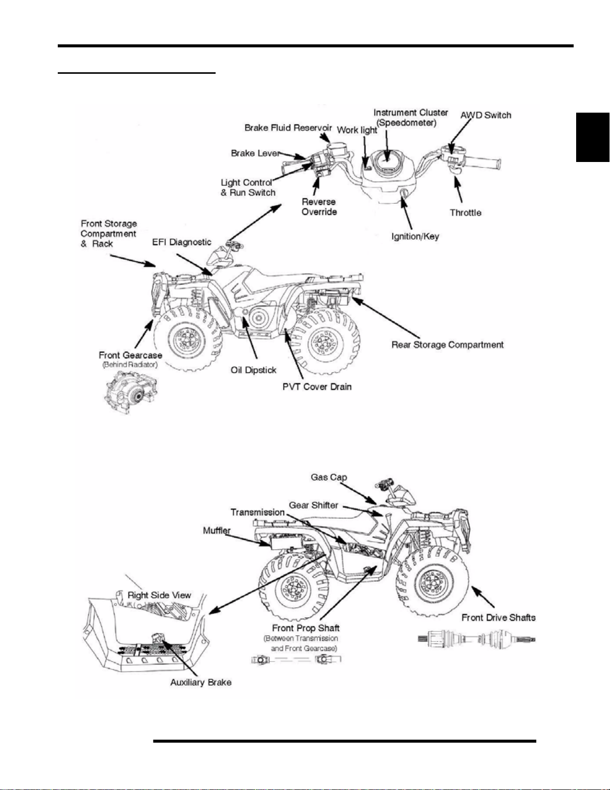
LUBRICATION / FLUIDS
SPORTSMAN Component Locations
MAINTENANCE
(Deluxe)
2
(Sportsman Only)
2.7
MAINTENANCE
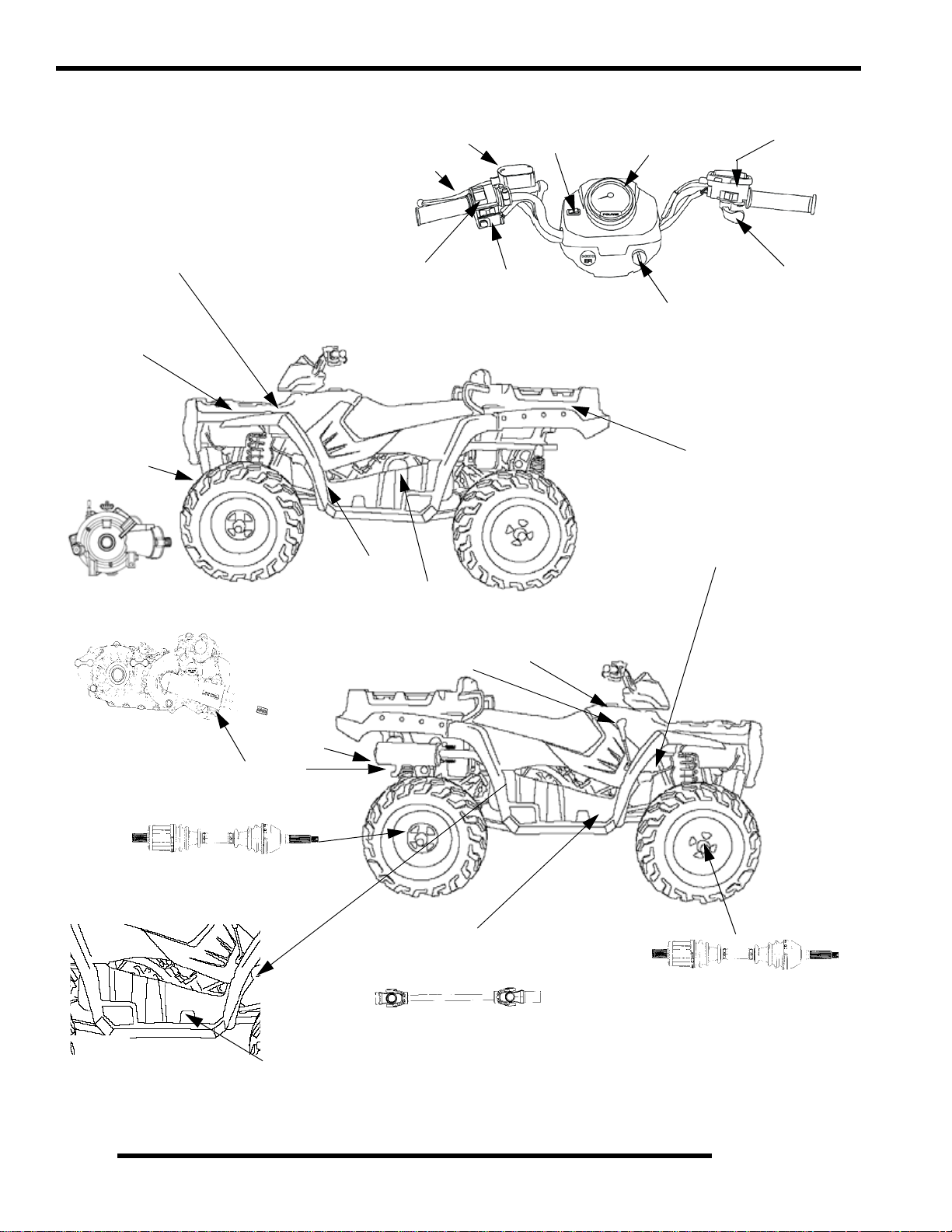
SPORTSMAN X2 Component locations
Brake Fluid Reservoir
Brake Lever
Worklight
Instrument Cluster
(Speedometer)
AWD/Turf Switch
Diagnostic
Port (under access panel)
Front St orage
Compartment
& Rack
Front Demand
Drive Unit
(Behind Radiator)
Light Control
& Run Switch
Oil Dipstick
PVT Cover
Gear Shifter
Reverse
Override
Gas Cap
Throttle
Ignition/Key
Rear Dump Box / Passenger Area
Battery (Under Tank)
2.8
Transmission
Rear Drive CV Shafts
Right Side View
Muffler
Auxiliary Brake
Front Prop Shaft
(Between Transmission
and Front Gearcase)
Front Drive CV Shafts
MAINTENANCE
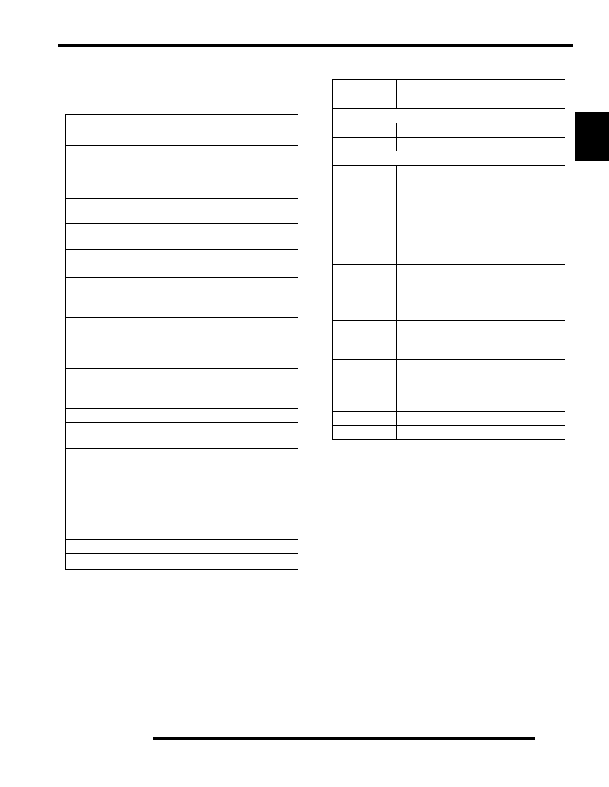
Polaris Lubricants, Maintenance and Service Products
Table 2-1:
PART
NUMBER
Engine Lubricant
2870791 Fogging Oil (12 oz. Aerosol)
2871281
2871844
2871567
Gearcase / Transmission Lubricants
2876251 Demand Drive L T Premium Hub Fluid
3234438 Polaris ADC Hydraulic Fluid
2873602
2873603
2876160
2872276
2870465 Oil Pump for 1 Gallon Jug
2871322
2871423
2871460 Starter Drive Grease (12 count)
2871515
2871551
2871312 Grease Gun Kit
2871329
Engine Oil (Quart) Premium Synthetic
Engine Oil (Gallon) Premium Synthetic
Engine Oil (16 Gallon) Premium 4
Premium Synthetic AGL Gearcase Lube
Premium Synthetic AGL Gearcase Lube
Premium ATV Angle Drive Fluid
Premium ATV Angle Drive Fluid
Grease / Specialized Lubricants
DESCRIPTION
0W-40 (4-cycle) (12 count)
0W-40 (4-cycle) (4 count)
Synthetic 0W-40 (4-cycle)
(12 oz. bottle) (12 count)
(1 Gal. bottle) (4 count)
(32 oz.) (12 count)
(2.5 Gal.) (2 count)
Premium All Season Grease
(3 oz. cartridge) (24 count)
Premium All Season Grease
(14 oz. cartridge) (10 count)
Premium U-Joint Lube
(3 oz.) (24 Count)
Premium U-Joint Lube
(14 oz.) (10 count)
Dielectric Grease (Nyogel
Table 2-1:
PART
NUMBER
2871323 60/40 Coolant (Gallon) (6 count)
2871534 60/40 Coolant (Quart) (12 count)
Additives / Sealants / Thread Locking Agents / Misc.
2874275
2871956
2871950
2871951
2871953
2871557
2871326
2870652 Fuel Stabilizer (16 oz.) (12 count)
2871957
2871958
2870990 DOT 3 Brake Fluid (12 count)
2871557 Crankcase Sealant, 3 Bond 1215 (5 oz.)
DESCRIPTION
Coolant
Loctite
Primer N, Aerosol
Loctite
Thread Sealant 565
(50 ml.) (6 count)
Loctite
Threadlock 242
(6 ml.) (12 count)
Loctite
Threadlock 262
(50 ml.) (10 count)
Loctite
Threadlock 271
(6 ml.) (12 count)
3-Bond 1215
Premium Carbon Clean
(12 oz.) (12 count)
Black RTV Silicone Sealer
(3 oz. tube ) (12 count)
Black RTV Silicone Sealer
(11 oz. cartridge) (12 count)
Sealant
(5 oz.)
2
2.9
MAINTENANCE
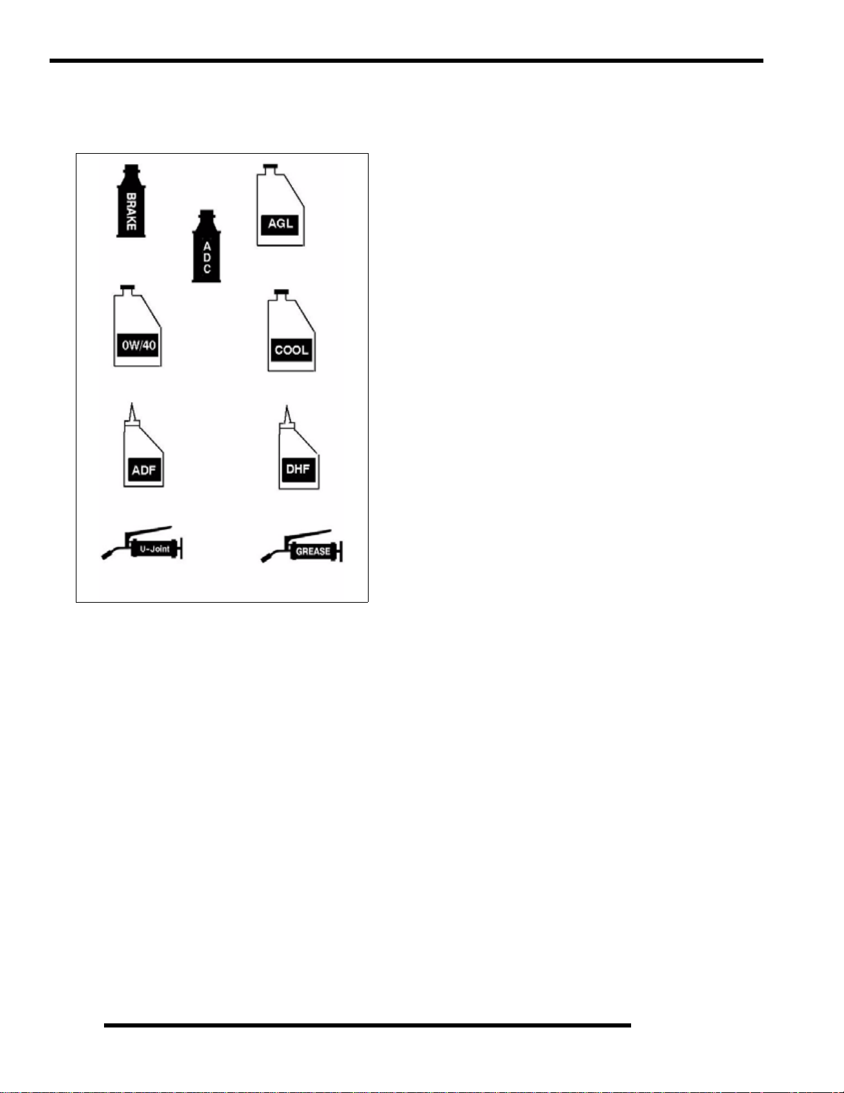
Polaris Lubricant Symbol Identification
NOTE: The symbols used are for quick reference in identifying
which lubricant/grease to use on each component.
Polaris DOT
Brake Fluid
Polaris ADC
Hydraulic Fluid
Polaris Synthetic
0W/40
Polaris ATV Angle
Drive Fluid
Polaris Synthetic AGL
Gearcase Lube
Polaris 60/40
Coolant
Polaris Demand Drive
LT Hub Fluid
Pre-ride / Daily Inspection
Perform the following pre-ride inspection daily, and when
servicing the vehicle at each scheduled maintenance.
• Verify seat lock-out operation
• Verify box lock-out operation
• Tires - check condition and pressures
• Fuel and oil tanks - fill both tanks to their proper level;
Do not overfill oil tank
• All brakes - check operation and adjustment (includes
auxiliary brake)
• Throttle -check for free operation
• Headlight/Taillight/Brakelight - check operation of all
indicator lights and switches
• Engine stop switch - check for proper function
• Wheels - check for loose wheel nuts and axle nuts;
check to be sure axle nuts are secured by cotter pins
• Air cleaner element - check for dirt or water; clean or
replace
• Steering - check for free operation, noting any unusual
looseness in any area
• Loose parts - visually inspect vehicle for any damaged
or loose nuts, bolts or fasteners
Polaris U-Joint Lube
Polaris All
Season Grease
• Engine coolant - check for proper level at the recovery
bottle
• ADC Fluid Level - check for proper level
2.10
Loading...