


GENERAL INFORMATION
CHAPTER 1 1
GENERAL INFORMATION
MODEL INFORMATION . . . . . . . . . . . . . . . . . . . . . . . . . . . . . . . . . . . . . . . . . . . . . . . . . . 1.2
MODEL IDENTIFICATION . . . . . . . . . . . . . . . . . . . . . . . . . . . . . . . . . . . . . . . . . . . . . . . . 1.2 ENGINE DESIGNATION NUMBER . . . . . . . . . . . . . . . . . . . . . . . . . . . . . . . . . . . . . . . . . 1.2 VIN IDENTIFICATION . . . . . . . . . . . . . . . . . . . . . . . . . . . . . . . . . . . . . . . . . . . . . . . . . . . 1.2 ENGINE SERIAL NUMBER LOCATION . . . . . . . . . . . . . . . . . . . . . . . . . . . . . . . . . . . . . 1.2 UNIT SERIAL NUMBER (VIN) LOCATION . . . . . . . . . . . . . . . . . . . . . . . . . . . . . . . . . . . 1.3
VEHICLE INFORMATION . . . . . . . . . . . . . . . . . . . . . . . . . . . . . . . . . . . . . . . . . . . . . . . . . 1.4
PUBLICATION NUMBERS. . . . . . . . . . . . . . . . . . . . . . . . . . . . . . . . . . . . . . . . . . . . . . . . 1.4 PAINT CODES . . . . . . . . . . . . . . . . . . . . . . . . . . . . . . . . . . . . . . . . . . . . . . . . . . . . . . . . . 1.4 REPLACEMENT KEYS . . . . . . . . . . . . . . . . . . . . . . . . . . . . . . . . . . . . . . . . . . . . . . . . . . 1.4
SPECIAL TOOLS . . . . . . . . . . . . . . . . . . . . . . . . . . . . . . . . . . . . . . . . . . . . . . . . . . . . . . . 1.4 GENERAL SPECIFICATIONS. . . . . . . . . . . . . . . . . . . . . . . . . . . . . . . . . . . . . . . . . . . . . . 1.5
GENERAL: 2009 RANGER RZR . . . . . . . . . . . . . . . . . . . . . . . . . . . . . . . . . . . . . . . . . . . 1.5 GENERAL: 2009 RANGER RZR “S” . . . . . . . . . . . . . . . . . . . . . . . . . . . . . . . . . . . . . . . . 1.5 DETAILED: 2009 RANGER RZR . . . . . . . . . . . . . . . . . . . . . . . . . . . . . . . . . . . . . . . . . . . 1.6 DETAILED: 2009 RANGER RZR “S” . . . . . . . . . . . . . . . . . . . . . . . . . . . . . . . . . . . . . . . . 1.7
MISC. SPECIFICATIONS AND CHARTS . . . . . . . . . . . . . . . . . . . . . . . . . . . . . . . . . . . . . 1.8
CONVERSION TABLE . . . . . . . . . . . . . . . . . . . . . . . . . . . . . . . . . . . . . . . . . . . . . . . . . . . 1.8 STANDARD TORQUE SPECIFICATIONS. . . . . . . . . . . . . . . . . . . . . . . . . . . . . . . . . . . . 1.9 SAE TAP / DRILL SIZES . . . . . . . . . . . . . . . . . . . . . . . . . . . . . . . . . . . . . . . . . . . . . . . . 1.10 METRIC TAP / DRILL SIZES . . . . . . . . . . . . . . . . . . . . . . . . . . . . . . . . . . . . . . . . . . . . . 1.10 DECIMAL EQUIVALENTS . . . . . . . . . . . . . . . . . . . . . . . . . . . . . . . . . . . . . . . . . . . . . . . 1.10 GLOSSARY OF TERMS. . . . . . . . . . . . . . . . . . . . . . . . . . . . . . . . . . . . . . . . . . . . . . . . . 1.11
1.1

GENERAL INFORMATION
MODEL INFORMATION
Model Identification
The machine model number must be used with any correspondence regarding warranty or service.
|
|
|
|
|
|
|
Machine Model Number Identification |
|
|
|
|
||||||||||||||||||
|
|
|
|
|
|
|
|
|
|
R |
0 9 |
|
V H |
7 6 |
A D |
|
|
|
|
|
|
|
|
|
|||||
|
|
|
|
|
|
|
|
|
|
|
|
} } } } |
|
|
|
|
|
|
|
|
|||||||||
|
|
|
|
|
|
Model Year |
|
|
|
|
|
|
|
|
|
|
|
Emissions & |
|
|
|
||||||||
|
|
|
|
|
|
|
|
|
|
|
|
|
|
|
|
|
Model Option |
||||||||||||
|
|
|
|
|
|
Designation |
|
|
Basic Chassis |
|
|
|
|||||||||||||||||
|
|
|
|
|
|
|
|
|
|
|
|
|
|
|
|
|
|
|
|
||||||||||
|
|
|
|
|
|
|
|
|
|
|
|
|
|
Engine Designation |
|
|
|
||||||||||||
|
|
|
|
|
|
|
|
|
|
|
|
Designation |
|
|
|
|
|
||||||||||||
|
|
|
|
|
|
|
|
|
|
|
|
|
|
|
|
|
|
|
|
|
|
|
|
||||||
Engine Designation Number |
|
|
|
|
|
|
|
|
|
|
|
|
|
|
|
|
|
|
|
|
|
|
|
|
|||||
EH076OLE022 ........................................................................ |
|
|
|
|
|
|
|
|
|
|
|
|
|
Twin Cylinder, Liquid Cooled, OHV 4 Stroke, Electric Start (RZR) |
|||||||||||||||
EH076OLE072 ................................................................. |
|
|
|
|
|
|
|
|
|
|
Twin Cylinder, Liquid Cooled, OHV 4 Stroke, Electric Start (RZR “S”) |
||||||||||||||||||
VIN Identification |
|
|
|
|
|
|
|
|
|
|
|
|
|
|
|
|
|
|
|
|
|
|
|
|
|
|
|
|
|
|
|
World |
|
Vehicle Description |
|
|
|
|
|
|
Vehicle Identifier |
|
|
|
|
||||||||||||||
|
Mfg. ID |
|
|
|
|
|
|
|
|
|
|
|
|||||||||||||||||
1 |
2 |
3 |
4 |
5 |
6 |
7 |
8 |
9 |
|
10 |
11 |
12 |
13 |
14 |
|
15 |
16 |
17 |
|
||||||||||
|
4 X A |
V H 7 6 A * |
9 P 0 0 0 0 0 0 |
|
|||||||||||||||||||||||||
|
|
|
|
|
|
|
|
} |
|
|
|
|
|
|
|
|
|
|
|
|
|
|
|
|
|
|
|
||
|
|
|
|
|
|
|
|
|
|
|
|
|
|
|
|
|
|
|
|
|
|
|
|
|
|
|
|
|
|
|
|
|
|
|
|
|
|
|
|
|
|
Model |
|
|
|
|
|
|
|
|
|
|
|
|
|
|
|||
|
|
|
|
|
|
|
|
Engine |
|
|
|
Year |
|
|
|
|
Individual |
|
Serial No. |
|
|
|
|||||||
|
|
|
|
|
|
|
|
|
|
|
|
|
|
|
|
|
|
|
|||||||||||
|
|
|
Body Style |
|
|
|
|
|
|
|
|
|
|
|
|||||||||||||||
|
|
|
|
|
|
|
|
|
|
|
|
|
|
|
|
|
|
|
|
|
|
|
|
|
|
||||
|
|
|
|
|
|
|
|
Emissions |
|
Plant |
No. |
|
|
|
|
|
|
* This could be either |
|||||||||||
|
|
|
|
Powertrain |
|
Check Digit |
|
|
|
|
|
|
|
|
|
|
|
a number or a letter |
|||||||||||
|
|
|
|
|
|
|
|
|
|
|
|
|
|
|
|
|
|
|
|
|
|
|
|
||||||
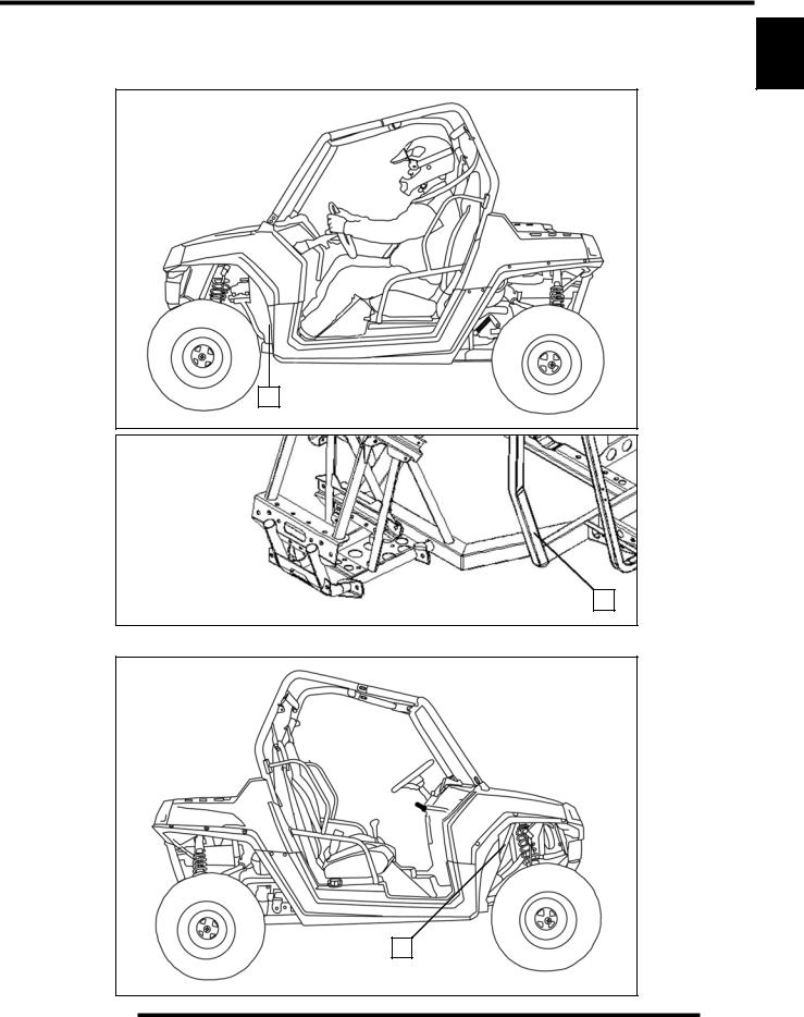
Engine Serial Number Location
Whenever corresponding about an engine, be sure to refer to the engine model number and serial number. This information can be found on the sticker applied to the cylinder head on the side of engine.
1.2
GENERAL INFORMATION
Unit Serial Number (VIN) Location
The machine model number and serial number (VIN) are important for vehicle identification. The VIN number (A) is stamped on a portion of the front left frame rail close to the left front wheel.
A |
A |
1 |
The VIN and model number are also located on a decal (B) attached to the frame support accessible through the front right wheel well.
B |
1.3

GENERAL INFORMATION
VEHICLE INFORMATION
Publication Numbers
Model |
Model No. |
Owner’s Manual PN |
Parts Manual PN |
|
|
|
|
2009 RANGER RZR |
R08VH76AD, AG, AH, AO |
9921878 |
9921879 |
|
|
|
|
2009 RANGER RZR “S” |
R08VH76AX |
9921878 |
9922130 |
|
|
|
|
NOTE: When ordering service parts be sure to use the correct parts manual.
NOTE: Polaris factory publications can be found at www.polarisindustries.com or purchased from www.purepolaris.com.
Paint Codes
Painted Part |
Color Description |
Polaris Number |
|
|
|
Frame / Bumpers / Racks |
Gloss Black |
P-067 |
|
|
|
Frame / Bumpers / Racks |
Matte Black |
P-458 |
|
|
|
Plastic - Hood / Dash / Fenders |
Indy Red |
P-293 |
|
|
|
Plastic - Hood / Dash / Fenders |
Sage Brush Green Metallic |
P-498 |
|
|
|
Replacement Keys
Replacement keys can be made from the original key. To identify which series the key is, take the first two digits on the original key and refer to the chart to the right for the proper part number.
|
|
|
|
KEY COVER |
|
Series# |
Part Number |
|
20 |
4010278 |
|
P/N 5533534 |
|
||
|
21 |
4010278 |
|
|
|
||
|
|
22 |
4010321 |
|
|
23 |
4010321 |
Key Series |
|
27 |
4010321 |
|
28 |
4010321 |
|
Number |
|
||
|
31 |
4110141 |
|
|
|
||
|
|
32 |
4110148 |
|
|
67 |
4010278 |
|
|
68 |
4010278 |
|
|
|
|
SPECIAL TOOLS
Special tools may be required while servicing this vehicle. Some of the tools listed or depicted are mandatory, while other tools maybe substituted with a similar tool, if available. Polaris recommends the use of Polaris Special Tools when servicing any Polaris product. Dealers may order special tools through Polaris’ official tool supplier, SPX Corporation, by phone at 1-800-328-6657 or on-line at http://polaris.spx.com/.
1.4
GENERAL INFORMATION
GENERAL SPECIFICATIONS
MODEL: 2009 RANGER RZR
MODEL NUMBER: R09VH76AD, AG, AH, AO
ENGINE MODEL: EH076OLE022
Category |
Dimension / Capacity |
|
|
|
|
Length |
102 in. / 259 cm |
|
|
|
|
Width |
50 in. / 127 cm |
|
|
|
|
Height |
68.5 in. / 174 cm |
|
|
|
|
Wheel Base |
77 in. / 196 cm |
|
|
|
|
Ground Clearance |
10 in. / 25.4 cm |
|
|
|
|
Dry Weight |
945 lbs. / 429 kg |
|
|
|
|
Gross Vehicle Weight |
1727 lbs. / 783 kg |
|
|
|
|
Front Storage |
25 lbs. / 11.3 kg |
|
Capacity |
||
|
||
Cargo Box Dimension |
42 in. x 22 in. / 107 cm x 56 cm |
|
|
|
|
Cargo Box Capacity |
300 lbs. / 136 kg |
|
|
|
|
Maximum Weight |
740 lbs. / 336.4 kg |
|
(Includes rider(s), cargo, accessories |
||
Capacity (Payload) |
||
and trailer tongue weight) |
||
|
||
|
|
|
Hitch Towing Capacity |
1500 lbs. / 680 kg |
|
|
|
|
Hitch Tongue Capacity |
150 lbs. / 68 kg |
|
|
|
MODEL: 2009 RANGER RZR “S”
MODEL NUMBER: R09VH76AX
ENGINE MODEL: EH076OLE072
Category |
Dimension / Capacity |
|
|
|
|
Length |
106 in. / 269 cm |
|
|
|
|
Width |
60.5 in. / 154 cm |
|
|
|
|
Height |
70.5 in. / 179 cm |
|
|
|
|
Wheel Base |
77 in. / 196 cm |
|
|
|
|
Ground Clearance |
12 in. / 30.5 cm |
|
|
|
|
Dry Weight |
1000 lbs. / 454 kg |
|
|
|
|
Gross Vehicle Weight |
1782 lbs. / 808 kg |
|
|
|
|
Front Storage |
25 lbs. / 11.3 kg |
|
Capacity |
||
|
||
Cargo Box Dimension |
42 in. x 22 in. / 107 cm x 56 cm |
|
|
|
|
Cargo Box Capacity |
300 lbs. / 136 kg |
|
|
|
|
Maximum Weight |
740 lbs. / 336.4 kg |
|
(Includes rider(s), cargo, accessories |
||
Capacity (Payload) |
||
and trailer tongue weight) |
||
|
||
|
|
|
Hitch Towing Capacity |
1500 lbs. / 680 kg |
|
|
|
|
Hitch Tongue Capacity |
150 lbs. / 68 kg |
|
|
|
1 |
1.5

GENERAL INFORMATION
MODEL: 2009 RANGER RZR
MODEL NUMBER: R09VH76AD, AG, AH, AO ENGINE MODEL: EH076OLE022
Engine |
||
Platform |
Polaris Domestic Twin Cylinder, |
|
Liquid Cooled, 4-Stroke |
||
|
||
|
|
|
Engine Model Number |
EH076OLE022 |
|
|
|
|
Engine Displacement |
760cc |
|
|
|
|
Number of Cylinders |
2 |
|
|
|
|
Bore & Stroke (mm) |
80 x 76.5 mm |
|
|
|
|
Compression Ratio |
9.78:1 |
|
|
|
|
Compression Pressure |
150-170 psi |
|
|
|
|
Engine Idle Speed |
1150 ± 100 RPM |
|
|
|
|
Engine Max Operating RPM |
6500 ± 200 RPM |
|
|
|
|
Lubrication |
Pressurized Wet Sump |
|
|
|
|
Oil Requirements |
PS-4 PLUS / 2W-50 Synthetic |
|
|
|
|
Oil Capacity |
2 qts. / 1.9 liters |
|
|
|
|
Coolant Capacity |
4.8 qts. / 4.5 liters |
|
|
|
|
Overheat Warning |
Instrument Cluster Indicator |
|
|
|
|
Exhaust System |
Single Headpipe / Single Silencer |
|
|
|
|
Fuel |
System |
|
Fuel System Type |
Bosch Electronic Fuel Injection |
|
|
|
|
Fuel Delivery |
Electronic Fuel Pump (in tank) |
|
|
|
|
Fuel Pressure |
39 psi |
|
|
|
|
Fuel Filters |
See Chapter 4 |
|
|
|
|
Fuel Capacity / Requirement |
7 gal. (26.5 liters) |
|
87 Octane (minimum) |
||
|
||
|
|
|
Electrical |
||
Alternator Max Output |
500 Watts @ 3000 RPM |
|
|
|
|
Lights: Main Headlights |
2 - Single Beam 55 W / Halogen |
|
|
|
|
Tail / Brake |
2 - 5 Watts / 2 - 5 Watts |
|
|
|
|
Starting System |
Electric Start |
|
|
|
|
Ignition System |
Bosch EFI (ECU Controlled) |
|
|
|
|
Ignition Timing |
13° BTDC @ 1200 RPM |
|
|
|
|
Spark plug / Gap |
Champion RC7YC3 / |
|
.035 in. (0.9 mm) |
||
|
||
|
|
|
Battery |
Yuasa YTX20HL / |
|
18 Amp Hr. / 310 CCA / 12 Volt |
||
|
||
|
|
|
Instrument Type |
Analog Speedometer |
|
with Multifunction LCD |
||
|
||
|
|
|
DC Outlet |
Standard 12 V |
|
|
|
|
Relays |
EFI / Fan |
|
|
|
|
Circuit Breaker |
Fan Motor: 20 Amp |
|
|
|
|
|
Chassis: 20 Amp |
|
|
EFI: 15 Amp |
|
Fuses |
Lights: 15 Amp |
|
|
Accessory: 15 Amp |
|
|
Speedo/ECU: 5 Amp |
|
|
|
|
|
|
|
|
Drivetrain |
|
||
|
Transmission Type |
|
Polaris Automatic PVT |
||||
|
|
|
|
|
|
|
|
|
Gear Ratio: Front / Rear |
|
|
|
|||
|
|
High |
|
|
3.14:1 |
||
|
|
Low |
|
|
8.71:1 |
||
|
|
Rev |
|
|
5.94:1 |
||
|
|
|
|
|
|
|
|
|
Drive Ratio - Front |
|
3.82:1 |
||||
|
|
|
|
|
|
|
|
|
Drive Ratio - Final |
|
3.70:1 |
||||
|
|
|
|
|
|
|
|
|
|
Shift Type |
|
In Line Shift - H / L / N / R / P |
|||
|
|
|
|
|
|
|
|
|
Front Gearcase Oil Requirements |
|
Polaris Demand Drive LT |
||||
|
|
Premium Fluid |
|||||
|
|
|
|
|
|
6.75 oz. (200 ml) |
|
|
|
|
|
|
|
|
|
|
Transmission Oil Requirements |
Polaris High Performance AGL |
|||||
|
|
Main Gearcase |
|
|
24 oz. (710 ml) |
||
|
|
|
|
|
|
|
|
|
Transmission Oil Requirements |
Polaris High Performance AGL |
|||||
|
|
Transfer Case |
|
|
14 oz. (414 ml) |
||
|
|
|
|
|
|
|
|
|
Rear Gearcase Oil Requirements |
|
Polaris Premium ADF |
||||
|
|
26 oz. (769 ml) |
|||||
|
|
|
|
|
|
||
|
|
|
|
|
|
|
|
|
|
Belt |
|
|
3211113 |
||
|
|
|
|
|
|
|
|
|
|
Steering / |
Suspension |
|
|||
|
|
Front Suspension |
|
Independent Dual A-arm |
|||
|
|
|
w/Anti-Sway Bar |
||||
|
|
|
|
|
|
||
|
|
|
|
|
|
|
|
|
|
Front Travel |
|
|
9 in. / 23 cm |
||
|
|
|
|
|
|
|
|
|
|
Rear Suspension |
Rolled IRS w/Anti-Sway Bar |
||||
|
|
|
|
|
|
|
|
|
|
Rear Travel |
|
|
9.5 in. / 24 cm |
||
|
|
|
|
|
|
|
|
|
Shock Preload Adjustment |
|
Cam Adjustment |
||||
|
|
Front / Rear |
|
|
|||
|
|
|
|
|
|
||
|
|
|
|
|
|
|
|
|
|
Toe Out |
|
|
1/8-1/4 in. / 3-6.35 mm |
||
|
|
|
|
|
|
|
|
|
|
|
|
Wheels |
/ Brakes |
|
|
|
|
Front Wheel Size |
|
12 x 6 / 10 gauge |
|||
|
|
Front Tire Size |
|
|
Maxxis / 25 x 8 R12 |
||
|
|
|
|
|
|
|
|
|
|
Rear Wheel Size |
|
12 x 8 / 10 gauge |
|||
|
|
Rear Tire Size |
|
|
Maxxis / 25 x 10 R12 |
||
|
|
|
|
|
|
|
|
|
Tire Air Pressure - Front / Rear |
|
8 psi (55 kPa) |
||||
|
|
|
|
|
|
|
|
|
Brake - Front / Rear |
|
Foot Actuated - 4 Wheel |
||||
|
|
Hydraulic Disc |
|||||
|
|
|
|
|
|
||
|
|
|
|
|
|
|
|
|
|
Brake Fluid |
|
|
DOT 4 |
||
|
|
|
|
|
|
|
|
CLUTCH CHART |
|
|
|
|
|||
|
|
|
|
|
|
|
|
|
Altitude |
|
Shift Weight |
Drive Spring |
Driven |
||
|
|
Spring |
|||||
|
|
|
|
|
|
|
|
|
|
|
|
|
|
|
|
|
|
0-1500 |
|
20-62 |
|
Blue / Red |
Red or Yellow |
|
Meters |
(0-5000) |
|
(5631700) |
(7043199) |
(3234452) |
|
|
(Feet) |
1500-3700 |
|
20-58 |
|
Blue / Red |
Red or Yellow |
|
|
(5000 - 12000) |
|
(5631216) |
(7043199) |
(3234452) |
|
|
|
|
|
|
|
|
|
1.6

GENERAL INFORMATION
MODEL: 2009 RANGER RZR “S” |
|
|
|
|
|
|
|
|
|
|
|
|
|
|
Drivetrain |
|
1 |
||||
MODEL NUMBER: R09VH76AX |
|
Transmission Type |
|
Polaris Automatic PVT |
||||||
|
|
|
|
|
|
|
|
|||
ENGINE MODEL: EH076OLE072 |
|
Gear Ratio: Front / Rear |
|
|
|
|
||||
|
|
|
|
High |
|
|
3.14:1 |
|
||
Engine |
|
|
|
|
|
|||||
|
|
Low |
|
|
8.71:1 |
|
||||
Platform |
Polaris Domestic Twin Cylinder, |
|
|
Rev |
|
|
5.94:1 |
|
||
Liquid Cooled, 4-Stroke |
|
|
|
|
|
|
|
|
|
|
|
|
Drive Ratio - Front |
|
3.82:1 |
|
|||||
|
|
|
|
|
||||||
Engine Model Number |
EH076OLE072 |
|
|
|
|
|
|
|
|
|
|
Drive Ratio - Final |
|
3.70:1 |
|
||||||
|
|
|
|
|
||||||
Engine Displacement |
760cc HO |
|
|
|
|
|
|
|
|
|
|
|
Shift Type |
|
In Line Shift - H / L / N / R / P |
|
|||||
|
|
|
|
|
|
|||||
Number of Cylinders |
2 |
|
|
|
|
|
|
|
|
|
|
|
|
|
|
|
Polaris Demand Drive LT |
|
|||
|
|
|
|
|
|
|
|
|
||
Bore & Stroke (mm) |
80 x 76.5 mm |
|
Front Gearcase Oil Requirements |
|
Premium Fluid |
|
||||
Compression Ratio |
11:1 |
|
|
|
|
|
|
6.75 oz. (200 ml) |
|
|
|
|
|
Transmission Oil Requirements |
Polaris High Performance AGL |
|
|||||
Compression Pressure |
165-185 psi |
|
||||||||
|
|
|
|
Main Gearcase |
|
|
24 oz. (710 ml) |
|
||
Engine Idle Speed |
1250 ± 100 RPM |
|
|
|
|
|
||||
|
|
|
Transmission Oil Requirements |
Polaris High Performance AGL |
|
|||||
Engine Max Operating RPM |
6600 ± 200 RPM |
|
||||||||
|
|
Transfer Case |
|
|
14 oz. (414 ml) |
|
||||
|
|
|
|
|
|
|
||||
Lubrication |
Pressurized Wet Sump |
|
|
|
|
|
||||
|
|
|
|
|
|
|
|
|
||
|
Rear Gearcase Oil Requirements |
|
Polaris Premium ADF |
|
||||||
|
|
|
|
|
||||||
Oil Requirements |
PS-4 PLUS / 2W-50 Synthetic |
|
|
|
||||||
|
|
26 oz. (769 ml) |
|
|||||||
|
|
|
|
|
|
|
|
|
||
Oil Capacity |
2 qts. / 1.9 liters |
|
|
|
|
|
|
|
|
|
|
|
Belt |
|
|
3211130 |
|
||||
|
|
|
|
|
|
|
||||
Coolant Capacity |
4.8 qts. / 4.5 liters |
|
|
|
|
|
|
|
|
|
|
|
Steering / Suspension |
|
|
||||||
|
|
|
|
|
|
|||||
Overheat Warning |
Instrument Cluster Indicator |
|
|
|
|
|
|
|
|
|
|
Front Suspension / Shock |
|
Independent Dual A-arm |
|
||||||
|
|
|
|
|
||||||
Exhaust System |
Dual Headpipe / Single Silencer |
|
|
FOX™ PODIUM X |
|
|||||
|
|
|
|
|
|
|
||||
Fuel |
System |
|
|
Front Travel |
|
|
12 in. / 30.5 cm |
|
||
Fuel System Type |
Bosch Electronic Fuel Injection |
|
Rear Suspension / Shock |
Rolled IRS w/Anti-Sway Bar |
|
|||||
|
|
|
|
FOX™ PODIUM X |
|
|||||
Fuel Delivery |
Electronic Fuel Pump (in tank) |
|
|
|||||||
|
|
|
|
|
|
|
||||
|
|
|
|
Rear Travel |
|
|
12 in. / 30.5 cm |
|
||
Fuel Pressure |
39 psi |
|
|
|
|
|
||||
|
|
|
Shock Preload Adjustment |
Threaded Shock Adjustment |
|
|||||
Fuel Filters |
See Chapter 4 |
|
||||||||
|
|
|
|
Front / Rear |
|
|
with Spanner Wrench |
|
||
Fuel Capacity / Requirement |
7 gal. (26.5 liters) |
|
|
|
|
|
||||
87 Octane (minimum) |
|
|
Toe Out |
|
|
1/8-1/4 in. / 3-6.35 mm |
|
|||
|
|
|
|
|
|
|||||
Electrical |
|
|
|
|
Wheels / Brakes |
|
|
|||
Alternator Max Output |
500 Watts @ 3000 RPM |
|
|
Front Wheel Size |
|
12 x 6 / Cast Aluminum |
|
|||
|
|
|
|
Front Tire Size |
|
Maxxis Bighorn / 26 x 9 R12 |
|
|||
Lights: Main Headlights |
2 - Single Beam 55 W / Halogen |
|
|
|
|
|||||
|
|
|
|
Rear Wheel Size |
|
12 x 8 / Cast Aluminum |
|
|||
Tail / Brake |
2 - 5 Watts / 2 - 5 Watts |
|
|
|
|
|||||
|
|
Rear Tire Size |
|
Maxxis Bighorn / 26 x 12 R12 |
|
|||||
|
|
|
|
|
|
|||||
Starting System |
Electric Start |
|
|
|
|
|||||
|
|
|
|
|
|
|
|
|
||
|
Tire Air Pressure - Front / Rear |
|
8 psi (55 kPa) |
|
||||||
|
|
|
|
|
||||||
Ignition System |
Bosch EFI (ECU Controlled) |
|
|
|||||||
|
|
|
|
|
|
|
|
|
||
|
Brake - Front / Rear |
|
Foot Actuated - 4 Wheel |
|
||||||
|
|
|
|
|
||||||
Ignition Timing |
13° BTDC @ 1200 RPM |
|
|
|
||||||
|
|
Hydraulic Disc |
|
|||||||
|
|
|
|
|
|
|
|
|
||
|
Champion RC7YC3 / |
|
|
|
|
|
|
|
|
|
Spark plug / Gap |
|
|
Brake Fluid |
|
|
DOT 4 |
|
|||
.035 in. (0.9 mm) |
|
|
|
|
|
|||||
|
|
CLUTCH CHART |
|
|
|
|
|
|||
|
|
|
|
|
|
|
|
|||
Battery |
Yuasa YTX20HL / |
|
|
|
|
|
||||
18 Amp Hr. / 310 CCA / 12 Volt |
|
|
|
|
|
|
|
|
|
|
|
|
|
|
|
|
|
|
|
|
|
Instrument Type |
Analog Speedometer |
|
Altitude |
|
Shift Weight |
Drive Spring |
Driven |
|
||
|
|
Spring |
|
|||||||
with Multifunction LCD |
|
|
|
|
|
|
|
|
||
|
|
|
|
|
|
|
|
|
|
|
|
|
|
|
0-1500 |
|
21-74 |
|
Red / White |
Red or Yellow |
|
DC Outlet |
Standard 12 V |
|
|
|
|
|||||
|
Meters |
(0-5000) |
|
(5632117) |
(7043349) |
(3234452) |
|
|||
|
|
|
|
|
||||||
Relays |
EFI / Fan |
|
||||||||
|
(Feet) |
|
|
|
|
|
|
|
||
|
1500-3700 |
|
21-70 |
|
Red / White |
Red or Yellow |
|
|||
|
|
|
|
|
|
|||||
Circuit Breaker |
Fan Motor: 20 Amp |
|
|
(5000 - 12000) |
|
(5632127) |
(7043349) |
(3234452) |
|
|
|
|
|
|
|
|
|
|
|
|
|
|
Chassis: 20 Amp |
|
|
|
|
|
|
|
|
|
|
|
|
|
|
|
|
|
|
|
|
|
EFI: 15 Amp |
|
|
|
|
|
|
|
|
|
Fuses |
Lights: 15 Amp |
|
|
|
|
|
|
|
|
|
|
Accessory: 15 Amp |
|
|
|
|
|
|
|
|
|
|
Speedo/ECU: 5 Amp |
|
|
|
|
|
|
|
|
|
|
|
|
|
|
|
|
|
|
|
|
1.7

GENERAL INFORMATION
MISC. SPECIFICATIONS AND CHARTS
Conversion Table
°C to °F: 9/5(°C + 32) = °F |
°F to °C: 5/9(°F - 32) = °C |
1.8
GENERAL INFORMATION
Standard Torque Specifications
The following torque specifications are to be used only as a general guideline. There are exceptions in the steering, suspension, and engine areas. Always consult the exploded views or each manual section for torque values of fasteners before using standard torque.
1 |
1.9

GENERAL INFORMATION
SAE Tap / Drill Sizes |
Decimal Equivalents |
Metric Tap / Drill Sizes
1.10
GENERAL INFORMATION
Glossary of Terms
ABDC: After bottom dead center. ACV: Alternating current voltage.
Alternator: Electrical generator producing voltage alternating current. ATDC: After top dead center.
BBDC: Before bottom dead center. BDC: Bottom dead center. BTDC: Before top dead center. CC: Cubic centimeters.
Center Distance: Distance between center of crankshaft and center of driven clutch shaft.
Chain Pitch: Distance between chain link pins (No. 35 = 3/8" or 1 cm). Polaris measures chain length in number of pitches. CI: Cubic inches.
Clutch Buttons: Plastic bushings which aid rotation of the movable sheave in the drive and driven clutch.
Clutch Offset: Drive and driven clutches are offset so that drive belt will stay nearly straight as it moves along the clutch face. Clutch Weights: Three levers in the drive clutch which relative to their weight, profile and engine RPM cause the drive clutch to close and grip the drive belt.
Crankshaft Run-Out: Run-out or "bend" of crankshaft measured with a dial indicator while crankshaft is supported between centers on V blocks or resting in crankcase. Measure at various points especially at PTO.
DCV: Direct current voltage
CVT: Centrifugal Variable Transmission (Drive Clutch System) DCV: Direct current voltage.
Dial Bore Gauge: A cylinder measuring instrument which uses a dial indicator. Good for showing taper and out-of-round in the cylinder bore.
Electrical Open: Open circuit. An electrical circuit which isn't complete.
Electrical Short: Short circuit. An electrical circuit which is completed before the current reaches the intended load. (i.e. a bare wire touching the chassis).
End Seals: Rubber seals at each end of the crankshaft.
Engagement RPM: Engine RPM at which the drive clutch engages to make contact with the drive belt. ft.: Foot/feet.
Foot Pound: Ft. lb. A force of one pound at the end of a lever one foot in length, applied in a rotational direction. g: Gram. Unit of weight in the metric system.
gal.: Gallon.
ID: Inside diameter. in.: Inch/inches.
Inch Pound: In. lb. 12 in. lbs. = 1 ft. lb. kg/cm²: Kilograms per square centimeter. kg-m: Kilogram meters.
Kilogram/meter: A force of one kilogram at the end of a lever one meter in length, applied in a rotational direction. l or ltr: Liter.
lbs/in²: Pounds per square inch.
Left or Right Side: Always referred to based on normal operating position of the driver. m: Meter/meters.
Mag: Magneto.
Magnetic Induction: As a conductor (coil) is moved through a magnetic field, a voltage will be generated in the windings. Mechanical energy is converted to electrical energy in the stator.
mi.: Mile/miles.
mm: Millimeter. Unit of length in the metric system. 1 mm = approximately .040". Nm: Newton meters.
OD: Outside diameter.
Ohm: The unit of electrical resistance opposing current flow. oz.: Ounce/ounces.
Piston Clearance: Total distance between piston and cylinder wall. psi.: Pounds per square inch.
PTO: Power take off.
PVT: Polaris Variable Transmission (Drive Clutch system) qt.: Quart/quarts.
Regulator: Voltage regulator. Regulates battery charging system output at approx. 14.5 DCV as engine RPM increases. Reservoir Tank: The fill tank in the liquid cooling system.
Resistance: In the mechanical sense, friction or load. In the electrical sense, ohms, resulting in energy conversion to heat. RPM: Revolutions per minute.
Seized Piston: Galling of the sides of a piston. Usually there is a transfer of aluminum from the piston onto the cylinder wall. Possible causes: 1) improper lubrication; 2) excessive temperatures; 3) insufficient piston clearance; 4) stuck piston rings. Stator Plate: The plate mounted under the flywheel supporting the battery charging coils.
TDC: Top dead center. Piston's most outward travel from crankshaft.
Volt: The unit of measure for electrical pressure of electromotive force. Measured by a voltmeter in parallel with the circuit. Watt: Unit of electrical power. Watts = amperes x volts.
WOT: Wide open throttle.
1 |
1.11

GENERAL INFORMATION
NOTES
1.12

MAINTENANCE
CHAPTER 2
MAINTENANCE
. . . . . . . . . . . . . . . . . . . . . . . . . . . . . . . . . .PERIODIC MAINTENANCE CHART |
. . . . . . . |
2.3 |
2 |
PERIODIC MAINTENANCE OVERVIEW. . . . . . . . . . . . . . . . . . . . . . . . . . . . . . . . . . . . . |
2.3 |
|
|
BREAK-IN PERIOD . . . . . . . . . . . . . . . . . . . . . . . . . . . . . . . . . . . . . . . . . . . . . . . . . . . . . |
2.3 |
|
|
MAINTENANCE CHART KEY |
2.3 |
|
|
|
|
||
PRE-RIDE - 25 HOUR MAINTENANCE INTERVAL . . . . . . . . . . . . . . . . . . . . . . . . . . . . |
2.4 |
|
|
50 - 300 HOUR MAINTENANCE INTERVAL . . . . . . . . . . . . . . . . . . . . . . . . . . . . . . . . . . |
2.5 |
|
|
COMPONENT INSPECTION / SERVICE LOCATIONS . . . . . . . . . . . . . . . . . . . . . . . . . . 2.6
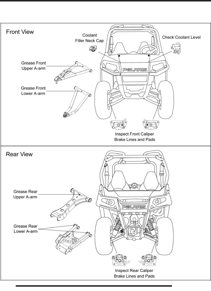
FRONT AND REAR VIEW . . . . . . . . . . . . . . . . . . . . . . . . . . . . . . . . . . . . . . . . . . . . . . . . 2.6 RH AND LH SIDE VIEWS. . . . . . . . . . . . . . . . . . . . . . . . . . . . . . . . . . . . . . . . . . . . . . . . . 2.7
LUBRICANTS / SERVICE PRODUCTS . . . . . . . . . . . . . . . . . . . . . . . . . . . . . . . . . . . . . . 2.8 MAINTENANCE REFERENCES . . . . . . . . . . . . . . . . . . . . . . . . . . . . . . . . . . . . . . . . . . . . 2.9 GENERAL VEHICLE INSPECTION AND MAINTENANCE. . . . . . . . . . . . . . . . . . . . . . . 2.10
PRE-RIDE / DAILY INSPECTION . . . . . . . . . . . . . . . . . . . . . . . . . . . . . . . . . . . . . . . . . 2.10 FRAME, NUTS, BOLTS, AND FASTENERS . . . . . . . . . . . . . . . . . . . . . . . . . . . . . . . . . 2.10 SHIFT CABLE INSPECTION / ADJUSTMENT. . . . . . . . . . . . . . . . . . . . . . . . . . . . . . . . 2.10
FUEL SYSTEM AND AIR INTAKE . . . . . . . . . . . . . . . . . . . . . . . . . . . . . . . . . . . . . . . . . 2.11
FUEL SYSTEM. . . . . . . . . . . . . . . . . . . . . . . . . . . . . . . . . . . . . . . . . . . . . . . . . . . . . . . . 2.11 FUEL LINE . . . . . . . . . . . . . . . . . . . . . . . . . . . . . . . . . . . . . . . . . . . . . . . . . . . . . . . . . . . 2.11 FUEL PUMP / FUEL FILTERS . . . . . . . . . . . . . . . . . . . . . . . . . . . . . . . . . . . . . . . . . . . . 2.11 VENT LINES. . . . . . . . . . . . . . . . . . . . . . . . . . . . . . . . . . . . . . . . . . . . . . . . . . . . . . . . . . 2.11 THROTTLE PEDAL INSPECTION . . . . . . . . . . . . . . . . . . . . . . . . . . . . . . . . . . . . . . . . . 2.12 THROTTLE FREEPLAY ADJUSTMENT . . . . . . . . . . . . . . . . . . . . . . . . . . . . . . . . . . . . 2.12 THROTTLE CABLE REPLACEMENT . . . . . . . . . . . . . . . . . . . . . . . . . . . . . . . . . . . . . . 2.12 AIR FILTER SERVICE . . . . . . . . . . . . . . . . . . . . . . . . . . . . . . . . . . . . . . . . . . . . . . . . . . 2.14
ENGINE . . . . . . . . . . . . . . . . . . . . . . . . . . . . . . . . . . . . . . . . . . . . . . . . . . . . . . . . . . . . . . 2.16
ENGINE OIL LEVEL . . . . . . . . . . . . . . . . . . . . . . . . . . . . . . . . . . . . . . . . . . . . . . . . . . . . 2.16 ENGINE OIL AND FILTER SERVICE. . . . . . . . . . . . . . . . . . . . . . . . . . . . . . . . . . . . . . . 2.17 ENGINE BREATHER HOSE INSPECTION . . . . . . . . . . . . . . . . . . . . . . . . . . . . . . . . . . 2.18 ENGINE AND TRANSMISSION MOUNT LOCATIONS . . . . . . . . . . . . . . . . . . . . . . . . . 2.18 COMPRESSION AND LEAKDOWN TEST. . . . . . . . . . . . . . . . . . . . . . . . . . . . . . . . . . . 2.18 EXHAUST - SPARK ARRESTOR. . . . . . . . . . . . . . . . . . . . . . . . . . . . . . . . . . . . . . . . . . 2.18
TRANSMISSION AND GEARCASES . . . . . . . . . . . . . . . . . . . . . . . . . . . . . . . . . . . . . . . 2.19
TRANSMISSION / GEARCASE SPECIFICATION CHART . . . . . . . . . . . . . . . . . . . . . . 2.19 TRANSMISSION LUBRICATION . . . . . . . . . . . . . . . . . . . . . . . . . . . . . . . . . . . . . . . . . 2.19 FRONT GEARCASE LUBRICATION . . . . . . . . . . . . . . . . . . . . . . . . . . . . . . . . . . . . . . . 2.21 REAR GEARCASE LUBRICATION . . . . . . . . . . . . . . . . . . . . . . . . . . . . . . . . . . . . . . . . 2.22
COOLING SYSTEM. . . . . . . . . . . . . . . . . . . . . . . . . . . . . . . . . . . . . . . . . . . . . . . . . . . . . 2.23
COOLING SYSTEM OVERVIEW . . . . . . . . . . . . . . . . . . . . . . . . . . . . . . . . . . . . . . . . . . 2.23 COOLANT LEVEL INSPECTION . . . . . . . . . . . . . . . . . . . . . . . . . . . . . . . . . . . . . . . . . . 2.23 COOLANT STRENGTH / TYPE . . . . . . . . . . . . . . . . . . . . . . . . . . . . . . . . . . . . . . . . . . . 2.23 COOLING SYSTEM PRESSURE TEST. . . . . . . . . . . . . . . . . . . . . . . . . . . . . . . . . . . . . 2.24 COOLING SYSTEM HOSES . . . . . . . . . . . . . . . . . . . . . . . . . . . . . . . . . . . . . . . . . . . . . 2.24 RADIATOR . . . . . . . . . . . . . . . . . . . . . . . . . . . . . . . . . . . . . . . . . . . . . . . . . . . . . . . . . . . 2.24 COOLANT DRAIN / RADIATOR REMOVAL . . . . . . . . . . . . . . . . . . . . . . . . . . . . . . . . . 2.24
FINAL DRIVE / WHEEL AND TIRE . . . . . . . . . . . . . . . . . . . . . . . . . . . . . . . . . . . . . . . . . 2.25
WHEEL, HUB, AND SPINDLE TORQUE TABLE. . . . . . . . . . . . . . . . . . . . . . . . . . . . . . 2.25 WHEEL REMOVAL. . . . . . . . . . . . . . . . . . . . . . . . . . . . . . . . . . . . . . . . . . . . . . . . . . . . . 2.25 WHEEL INSTALLATION. . . . . . . . . . . . . . . . . . . . . . . . . . . . . . . . . . . . . . . . . . . . . . . . . 2.25 TIRE INSPECTION. . . . . . . . . . . . . . . . . . . . . . . . . . . . . . . . . . . . . . . . . . . . . . . . . . . . . 2.26 TIRE PRESSURE. . . . . . . . . . . . . . . . . . . . . . . . . . . . . . . . . . . . . . . . . . . . . . . . . . . . . . 2.26 DRIVE SHAFT BOOT INSPECTION . . . . . . . . . . . . . . . . . . . . . . . . . . . . . . . . . . . . . . . 2.26
2.1

MAINTENANCE
ELECTRICAL AND IGNITION SYSTEM . . . . . . . . . . . . . . . . . . . . . . . . . . . . . . . . . . . . . 2.27
BATTERY MAINTENANCE . . . . . . . . . . . . . . . . . . . . . . . . . . . . . . . . . . . . . . . . . . . . . . 2.27 BATTERY REMOVAL. . . . . . . . . . . . . . . . . . . . . . . . . . . . . . . . . . . . . . . . . . . . . . . . . . . 2.27 BATTERY INSTALLATION. . . . . . . . . . . . . . . . . . . . . . . . . . . . . . . . . . . . . . . . . . . . . . . 2.27 BATTERY OFF SEASON STORAGE . . . . . . . . . . . . . . . . . . . . . . . . . . . . . . . . . . . . . . 2.28 BATTERY CHARGING (SEALED BATTERY) . . . . . . . . . . . . . . . . . . . . . . . . . . . . . . . . 2.28 SPARK PLUG SERVICE . . . . . . . . . . . . . . . . . . . . . . . . . . . . . . . . . . . . . . . . . . . . . . . . 2.28 ENGINE TO FRAME GROUND . . . . . . . . . . . . . . . . . . . . . . . . . . . . . . . . . . . . . . . . . . . 2.29
STEERING . . . . . . . . . . . . . . . . . . . . . . . . . . . . . . . . . . . . . . . . . . . . . . . . . . . . . . . . . . . 2.29
STEERING INSPECTION . . . . . . . . . . . . . . . . . . . . . . . . . . . . . . . . . . . . . . . . . . . . . . . 2.29 STEERING WHEEL FREEPLAY . . . . . . . . . . . . . . . . . . . . . . . . . . . . . . . . . . . . . . . . . . 2.29 STEERING INSPECTION / TIE ROD ENDS AND HUBS . . . . . . . . . . . . . . . . . . . . . . . 2.30 TOE ALIGNMENT INSPECTION . . . . . . . . . . . . . . . . . . . . . . . . . . . . . . . . . . . . . . . . . . 2.30 TOE ADJUSTMENT . . . . . . . . . . . . . . . . . . . . . . . . . . . . . . . . . . . . . . . . . . . . . . . . . . . . 2.31
SUSPENSION (RZR) . . . . . . . . . . . . . . . . . . . . . . . . . . . . . . . . . . . . . . . . . . . . . . . . . . . 2.31
SPRING PRELOAD ADJUSTMENT. . . . . . . . . . . . . . . . . . . . . . . . . . . . . . . . . . . . . . . . 2.31
SUSPENSION (RZR “S”). . . . . . . . . . . . . . . . . . . . . . . . . . . . . . . . . . . . . . . . . . . . . . . . . 2.32
SPRING PRELOAD ADJUSTMENT. . . . . . . . . . . . . . . . . . . . . . . . . . . . . . . . . . . . . . . . 2.32 SHOCK COMPRESSION ADJUSTMENT . . . . . . . . . . . . . . . . . . . . . . . . . . . . . . . . . . . 2.32
BRAKE SYSTEM. . . . . . . . . . . . . . . . . . . . . . . . . . . . . . . . . . . . . . . . . . . . . . . . . . . . . . . 2.33
BRAKE FLUID INSPECTION . . . . . . . . . . . . . . . . . . . . . . . . . . . . . . . . . . . . . . . . . . . . . 2.33 BRAKE PAD / DISC INSPECTION. . . . . . . . . . . . . . . . . . . . . . . . . . . . . . . . . . . . . . . . . 2.33 BRAKE HOSE AND FITTING INSPECTION . . . . . . . . . . . . . . . . . . . . . . . . . . . . . . . . . 2.33
2.2

MAINTENANCE
PERIODIC MAINTENANCE CHART
Periodic Maintenance Overview
Inspection, adjustment and lubrication of important components are explained in the periodic maintenance chart.
Inspect, clean, lubricate, adjust and replace parts as necessary. When inspection reveals the need for replacement parts, use genuine Pure Polaris parts available from your Polaris dealer.
NOTE: Service and adjustments are critical. If you’re not familiar with safe service and adjustment procedures, have a qualified dealer perform these operations.
2 |
Maintenance intervals in the following chart are based upon average riding conditions and an average vehicle speed of approximately 10 miles per hour. Vehicles subjected to severe use must be inspected and serviced more frequently.
Severe Use Definition
•Frequent immersion in mud, water or sand
•Racing or race-style high RPM use
•Prolonged low speed, heavy load operation
•Extended idle
•Short trip cold weather operation
Pay special attention to the oil level. A rise in oil level during cold weather can indicate contaminants collecting in the oil sump or crankcase. Change oil immediately if the oil level begins to rise. Monitor the oil level, and if it continues to rise, discontinue use and determine the cause or see your dealer.
Break-In Period
The break-in period consists of the first 25 hours of operation, or the time it takes to use 14 gallons (53 liters) of fuel. Careful treatment of a new engine and drive components will result in more efficient performance and longer life for these components.
•Drive vehicle slowly at first while varying the throttle position. Do not operate at sustained idle.
•Pull only light loads.
•Perform regular checks on fluid levels and other areas outlined on the daily pre-ride inspection checklist.
•Change both the engine oil and filter after 25 hours or one month.
•See “Owner’s Manual” for additional break-in information.
Maintenance Chart Key
The following symbols denote potential items to be aware of during maintenance:
= CAUTION: Due to the nature of these adjustments, it is recommended this service be performed by an authorized Polaris dealer.
= SEVERE USE ITEM: See information provided above.
E = Emission Control System Service (California).
NOTE: Inspection may reveal the need for replacement parts. Always use genuine Polaris parts.
 WARNING
Improperly performing the procedures marked could result in component failure and lead to serious injury or death. Have an authorized Polaris dealer perform these services.
2.3

MAINTENANCE
Pre-Ride - 25 Hour Maintenance Interval
|
|
|
Maintenance Interval |
|
||
|
Item |
|
(whichever comes first) |
Remarks |
||
|
Hours |
Calendar |
Miles |
|||
|
|
|
||||
|
|
(KM) |
|
|||
|
|
|
|
|
||
|
|
|
|
|
|
|
|
Steering |
- |
Pre-Ride |
- |
|
|
|
Front Suspension |
- |
Pre-Ride |
- |
|
|
|
|
|
|
|
|
|
|
Rear Suspension |
- |
Pre-Ride |
- |
|
|
|
|
|
|
|
|
|
|
Tires |
- |
Pre-Ride |
- |
|
|
|
Brake Fluid Level |
- |
Pre-Ride |
- |
Make adjustments as needed. |
|
|
|
|
|
|
||
|
Brake Pedal Travel |
- |
Pre-Ride |
- |
||
|
See Pre-Ride Checklist on Page 2.9. |
|||||
|
Brake Systems |
- |
Pre-Ride |
- |
|
|
|
Wheels / Fasteners |
- |
Pre-Ride |
- |
|
|
|
Frame Fasteners |
- |
Pre-Ride |
- |
|
|
E |
Engine Oil Level |
- |
Pre-Ride |
- |
|
|
|
|
|
|
|
|
|
E |
Air Filter / Pre-Filter |
- |
Pre-Ride |
- |
Inspect; clean often; replace as needed |
|
|
|
|
|
|
|
|
|
Coolant Level |
- |
Daily |
- |
Check level daily, change coolant every 2 |
|
|
years |
|||||
|
|
|
|
|
||
|
|
|
|
|
|
|
|
Head Lamp / Tail Lamp |
- |
Daily |
- |
Check operation; apply dielectric grease if |
|
|
replacing |
|||||
|
|
|
|
|
||
|
Air Filter, |
- |
Weekly |
- |
Inspect; replace as needed |
|
E |
Main Element |
|||||
|
|
|
|
|||
|
|
|
|
|
|
|
|
Brake Pad Wear |
10 H |
Monthly |
100 (160) |
Inspect periodically |
|
|
|
|
|
|
|
|
|
Battery |
25 H |
Monthly |
250 (400) |
Check terminals; clean; test |
|
|
Front Gearcase Oil |
25 H |
Monthly |
250 (400) |
Inspect level; change yearly |
|
|
(Demand Drive Fluid LT) |
|||||
|
|
|
|
|
||
|
Rear Gearcase Oil |
25 H |
Monthly |
250 (400) |
Inspect level; change yearly |
|
|
(ATV Angle Drive Fluid) |
|||||
|
|
|
|
|
||
|
|
|
|
|
|
|
|
Transmission - Main |
25 H |
Monthly |
250 (400) |
Inspect level; change yearly |
|
|
(AGL Gearcase Lubricant) |
|||||
|
|
|
|
|
||
|
|
|
|
|
|
|
|
Transmission - Transfer |
25 H |
Monthly |
250 (400) |
Inspect level; change yearly |
|
|
(AGL Gearcase Lubricant) |
|||||
|
|
|
|
|
||
|
Engine Breather |
25 H |
Monthly |
250 (400) |
Inspect; replace if necessary |
|
E |
Filter (if equipped) |
|||||
|
|
|
|
|||
|
Engine Oil Change |
25 H |
1 M |
250 (400) |
Perform a break-in oil change at one month |
|
E |
(Break-In Period) |
|||||
|
|
|
|
|||
Perform these procedures more often for vehicles subjected to severe use.
E Emission Control System Service (California)
Have an authorized Polaris dealer perform these services.
2.4
|
|
|
|
|
|
MAINTENANCE |
|
50 - 300 Hour Maintenance Interval |
|
|
|
|
|||
|
|
|
Maintenance Interval |
|
|
||
|
Item |
|
(whichever comes first) |
Remarks |
|
||
|
Hours |
Calendar |
Miles |
|
|||
|
|
|
|
||||
|
|
(KM) |
|
2 |
|||
|
Throttle Cable / Throttle |
|
|
Inspect; adjust; lubricate; replace if |
|||
|
50 H |
6 M |
300 |
(500) |
|||
E |
Pedal |
necessary |
|||||
E |
Throttle Body Air Intake |
50 H |
6 M |
300 |
(500) |
Inspect ducts for proper sealing / air leaks |
|
Ducts / Flange |
|
||||||
|
General Lubrication |
50 H |
3 M |
500 |
(800) Lubricate all fittings, pivots, cables, etc. |
|
|
|
Shift Linkage |
50 H |
6 M |
500 |
(800) |
Inspect, lubricate, adjust |
|
|
Steering |
50 H |
6 M |
500 |
(800) |
Lubricate |
|
|
Front Suspension |
50 H |
6 M |
500 |
(800) |
Lubricate |
|
|
Rear Suspension |
50 H |
6 M |
500 |
(800) |
Lubricate |
|
|
Cooling System |
50 H |
6 M |
500 |
(800) |
Inspect coolant strength seasonally; |
|
|
pressure test system yearly |
|
|||||
|
|
|
|
|
|
|
|
|
|
|
|
|
|
Check for leaks at tank cap, fuel line, fuel |
|
E |
Fuel System |
100 H |
12 M |
600 (1000) |
pump, and fuel rail. |
|
|
|
|
|
|
|
|
Replace lines every two years. |
|
E |
Spark Plug |
100 H |
12 M |
600 (1000) Inspect; replace as needed |
|
||
|
|
|
|
|
|
Perform a break-in oil change at 25 hours or |
|
E |
Engine Oil & Filter Change |
100 H |
6 M |
1000 |
(1600) |
one month / always replace oil filter when |
|
|
|
|
|
|
|
changing engine oil |
|
|
Drive Belt |
100 H |
12 M |
1000 |
(1600) Inspect; replace as needed |
|
|
|
Radiator |
100 H |
12 M |
1000 |
(1600) Inspect; clean external surfaces |
|
|
|
Cooling Hoses |
100 H |
12 M |
1000 |
(1600) |
Inspect for leaks |
|
|
Engine Assembly Mounts |
100 H |
12 M |
1000 |
(1600) Inspect, torque to specification |
|
|
|
Exhaust Muffler / Pipe |
100 H |
12 M |
1000 |
(1600) |
Inspect |
|
|
|
|
|
|
|
Inspect for wear, routing, security; apply |
|
|
Wiring |
100 H |
12 M |
1000 |
(1600) |
dielectric grease to connectors subjected to |
|
|
|
|
|
|
|
water, mud, etc. |
|
|
Clutches (Drive and Driven) |
100 H |
12 M |
1000 |
(1600) |
Inspect; clean; replace worn parts |
|
|
Front Wheel Bearings |
100 H |
12 M |
1000 |
(1600) Inspect; replace as needed |
|
|
|
Brake Fluid |
200 H |
24 M |
2000 |
(3200) |
Change every two years (DOT 4) |
|
|
Spark Arrestor |
300 H |
36 M |
3000 |
(4800) |
Clean out |
|
|
Toe Adjustment |
|
- |
|
|
Inspect periodically; adjust when parts are |
|
|
|
|
|
replaced |
|
||
|
|
|
|
|
|
|
|
|
Headlight Aim |
|
- |
|
|
Adjust as needed |
|
Perform these procedures more often for vehicles subjected to severe use.
EEmission Control System Service (California)
Have an authorized Polaris dealer perform these services.
2.5
MAINTENANCE
COMPONENT INSPECTION / SERVICE LOCATIONS
Front and Rear View
Standard RZR Shown
Standard RZR Shown
2.6
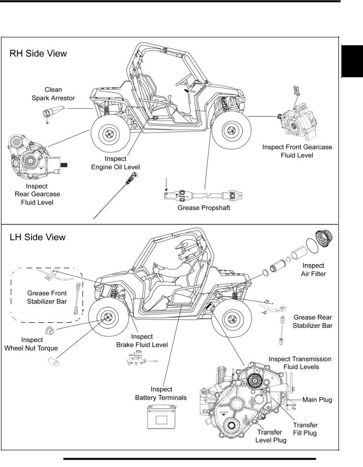
RH and LH Side Views
Standard RZR Shown
Standard RZR Shown
*Standard RZR Only
MAINTENANCE
2 |
2.7

MAINTENANCE
LUBRICANTS / SERVICE PRODUCTS
Polaris Lubricants, Maintenance and Service
Products
Part No. |
Description |
|
|
|
|
|
Engine Lubricant |
|
|
|
|
2870791 |
Fogging Oil (12 oz. Aerosol) |
|
|
|
|
2876244 |
PS-4 PLUS Performance Synthetic 2W-50 |
|
4-Cycle Engine Oil (Quart) |
||
|
|
|
2876245 |
PS-4 PLUS Performance Synthetic 2W-50 |
|
4-Cycle Engine Oil (Gallon) |
||
|
|
|
Gearcase / Transmission Lubricants |
||
|
|
|
2873602 |
AGL - Synthetic ATV Gearcase Lubricant |
|
(1 Qt.) (12 Count) |
||
|
||
|
|
|
2873603 |
AGL - Synthetic ATV Gearcase Lubricant |
|
(1 Gal.) (4 Count) |
||
|
||
|
|
|
2873604 |
AGL - Synthetic ATV Gearcase Lubricant |
|
(2.5 Gal.) (2 Count) |
||
|
||
|
|
|
2871653 |
ATV Angle Drive Fluid |
|
(8 oz.) (12 Count) |
||
|
||
|
|
|
2872276 |
ATV Angle Drive Fluid |
|
(2.5 Gal) (2 Count) |
||
|
||
|
|
|
2871654 |
Premium Demand Drive Fluid LT |
|
(1 Qt.) (12 Count) |
||
|
||
|
|
|
2870465 |
Oil Pump for 1 Gallon Jug |
|
|
|
|
Grease / Specialized Lubricants
2871312 |
Grease Gun Kit |
|
|
|
|
2871322 |
Premium All Season Grease |
|
(3 oz. cartridge) (24 Count) |
||
|
||
|
|
|
2871423 |
Premium All Season Grease |
|
(14 oz. cartridge) (10 Count) |
||
|
||
|
|
|
2871460 |
Starter Drive Grease (12 Count) |
|
|
|
|
2871515 |
Premium U-Joint Lube (3 oz.) (24 Count) |
|
|
|
|
2871551 |
Premium U-Joint Lube (14 oz.) (10 Count) |
|
|
|
|
2871329 |
Dielectric Grease (Nyogel™) |
|
|
|
|
|
Coolant |
|
|
|
|
2871323 |
60/40 Coolant (Gallon) (6 Count) |
|
|
|
|
2871534 |
60/40 Coolant (Quart) (12 Count) |
|
|
|
NOTE: Each item can be purchased separately at your local Polaris dealer.
Part No. |
Description |
|
|
Additives / Sealants / Thread Locking Agents / Misc.
2870585 |
Loctite™ Primer N, Aerosol, 25 g |
|
|
|
|
2871956 |
Loctite™ Thread Sealant 565 |
|
(50 ml.) (6 Count) |
||
|
||
|
|
|
2871949 |
Loctite™ Threadlock 242 |
|
(50 ml.) (10 Count) |
||
|
||
|
|
|
2871950 |
Loctite™ Threadlock 242 |
|
(6 ml.) (12 Count) |
||
|
||
|
|
|
2871951 |
Loctite™ Threadlock 262 |
|
(50 ml.) (10 Count) |
||
|
||
|
|
|
2871952 |
Loctite™ Threadlock 262 |
|
(6 ml.) (12 Count) |
||
|
||
|
|
|
2871953 |
Loctite™ Threadlock 271 |
|
(6 ml.) (12 Count) |
||
|
||
|
|
|
2871954 |
Loctite™ Threadlock 271 |
|
(36 ml.) (6 Count) |
||
|
||
|
|
|
2870584 |
Loctite™ 680-Retaining Compound |
|
(10 ml.) |
||
|
||
|
|
|
2870587 |
Loctite™ 518 Gasket Eliminator / Flange |
|
Sealant (50 ml.) (10 Count) |
||
|
||
|
|
|
2871326 |
Premium Carbon Clean |
|
(12 oz.) (12 Count) |
||
|
||
|
|
|
2870652 |
Fuel Stabilizer (16 oz.) (12 Count) |
|
|
|
|
2872189 |
DOT 4 Brake Fluid (12 Count) |
|
|
|
|
2871557 |
Crankcase Sealant, 3-Bond 1215 (5oz.) |
|
|
|
|
2872893 |
Engine Degreaser (12oz.) (12 Count) |
|
|
|
NOTE: The number count indicated by each part number in the table above indicates the number of units that are shipped with each order.
2.8
|
|
|
|
MAINTENANCE |
|
|
MAINTENANCE REFERENCES |
|
|
|
|||
Item |
Ref. |
Rec. Lube / Fluid |
Method |
Frequency* |
|
|
|
|
|
|
Change after 25 hrs, and then |
|
|
|
|
Polaris PS-4 PLUS |
|
6 months or 100 hours |
2 |
|
|
|
Add oil to proper level on |
thereafter; Change more |
|||
Engine Oil |
Page 2.7 |
Performance Synthetic |
||||
dipstick. |
often in extremely dirty |
|||||
|
|
2W-50 4-Cycle Engine Oil |
||||
|
|
|
conditions, or short trip cold |
|
||
|
|
|
|
|
||
|
|
|
|
weather operation. |
|
|
Engine Coolant |
Page 2.6 |
Polaris Antifreeze 60/40 |
Fill recovery bottle between |
Fill as required. Change |
|
|
(PN 2871534) |
MAX and MIN lines. |
coolant every 2 years. |
|
|||
|
|
|
||||
Brake Fluid |
Page 2.7 |
DOT 4 (PN 2872189) |
Fill reservoir between MAX |
Fill as required. Change |
|
|
and MIN lines. |
brake fluid every 2 years. |
|
||||
|
|
|
|
|||
Transmission |
Page 2.7 |
AGL Synthetic Gearcase |
Add lube to bottom of fill |
Change annually*** |
|
|
(Main Gearcase) |
Lubricant (PN 2873602) |
plug threads. 24 oz. (710 ml) |
|
|||
Transmission |
|
AGL Synthetic Gearcase |
Add lube to bottom of level |
|
|
|
Page 2.7 |
check plug threads. |
Change annually*** |
|
|||
(Transfer Case) |
Lubricant (PN 2873602) |
|
||||
|
14 oz. (414 ml) |
|
|
|||
|
|
|
|
|
||
|
|
Premium Demand Drive |
Add fluid to bottom of fill |
|
|
|
Front Gearcase |
Page 2.7 |
plug threads. |
Change annually*** |
|
||
Fluid LT (PN 2876251) |
|
|||||
|
|
6.75 oz. (200 ml) |
|
|
||
|
|
|
|
|
||
Rear Gearcase |
Page 2.7 |
ATV Angle Drive Fluid |
Add lube to bottom of fill |
Change annually*** |
|
|
(PN 2871653) |
plug threads. 26 oz. (769 ml) |
|
||||
Prop Shaft |
Page 2.7 |
Polaris Premium U-Joint |
Locate fitting and grease with |
Semi-annually** |
|
|
|
|
Lube (PN 2871551) |
grease gun. |
|
|
|
|
|
|
Locate grease fittings on the |
|
|
|
|
|
|
upper and lower A-arms of |
|
|
|
ControlArmPivot |
Page 2.6 |
Polaris Premium All Season |
the front and rear suspension |
Semi-annually** |
|
|
Bushings, FT / RR |
|
Grease (PN 2871423) |
and grease with grease gun. |
|
|
|
|
|
|
(4) Front A-arms |
|
|
|
|
|
|
(6) Rear A-arms |
|
|
|
|
|
|
Locate grease fittings on the |
|
|
|
Stabilizer Bar |
|
Polaris Premium All Season |
front and rear stabilizer bars |
|
|
|
Page 2.7 |
and grease with grease gun. |
Semi-annually** |
|
|||
Bushings, FT / RR |
|
Grease (PN 2871423) |
(2) Front Stabilizer Bar |
|
|
|
|
|
|
|
|
||
|
|
|
(2) Rear Stabilizer Bar |
|
|
|
* More often under severe use, such as operated in water or under severe loads.
**Semi-annually or 50 hours of operation (refer to Maintenance Schedule for additional information)
***Annually or 100 hours of operation (refer to Maintenance Schedule for additional information)
2.9

MAINTENANCE
GENERAL VEHICLE INSPECTION AND MAINTENANCE
Pre-Ride / Daily Inspection
Perform the following pre-ride inspection daily, and when servicing the vehicle at each scheduled maintenance.
•Tires - check condition and pressures
•Fuel tank - fill to proper level
•All brakes - check operation and adjustment
•Throttle - check for free operation and closing
•Headlights/Taillights/Brakelights - also check operation of all indicator lights and switches
•Ignition switch - check for proper function
•Wheels - check for tightness of wheel nuts and axle nuts; check to be sure axle nuts are secured by cotter pins
•Air cleaner element - check for dirt; clean or replace
•Steering - check for free operation noting any unusual looseness in any area
•Loose parts - visually inspect vehicle for any damaged or loose nuts, bolts or fasteners
•Engine coolant - check for proper level at the recovery bottle
•Check all front and rear suspension components for wear or damage.
Frame, Nuts, Bolts, and Fasteners
Periodically inspect the torque of all fasteners in accordance with the maintenance schedule. Check that all cotter pins are in place. Refer to specific fastener torques listed in each chapter.
Shift Cable Inspection / Adjustment
Shift cable adjustment may be necessary if symptoms include:
•No AWD or gear position display on instrument cluster
•Ratcheting noise on deceleration
•Inability to engage into a gear
•Excessive gear clash (noise)
•Gear selector moving out of desired range
1.Locate the shift cable in the rear LH wheel well area.
Clevis Pin |
Shift  Cable
Cable
Mount
Shift Cable |
|
Dust Boot |
2.Inspect shift cable, clevis pin, pivot bushings, and dust boot. Replace if worn or damaged.
3.If adjustment is required, loosen the lower jam nut and pull the cable out of the mount to move the upper jam nut.
Upper
Jam Nut
Nut
Lower
Jam Nut
4.Adjust the shift cable so there is the same amount of cable travel when shifting slightly past the detents of HIGH (H) gear and PARK (P).
5.Thread the upper or lower jam nut as required to obtain proper cable adjustment.
NOTE: This procedure may require a few attempts to obtain the proper adjustment.
2.10
MAINTENANCE
6.Once the proper adjustment is obtained, place the shift cable and upper jam nut into the mount. Tighten the lower jam nut against the mount.
7.Start engine and shift through all gears to ensure the shift cable is properly adjusted. If transmission still ratchets after cable adjustment, the transmission will require service.
FUEL SYSTEM AND AIR INTAKE
Fuel System
 WARNING
Gasoline is extremely flammable and explosive under certain conditions.
Always stop the engine and refuel outdoors or in a well ventilated area.
Do not smoke or allow open flames or sparks in or near the area where refueling is performed or where gasoline is stored.
Do not overfill the tank. Do not fill the tank neck. If you get gasoline in your eyes or if you swallow gasoline, seek medical attention immediately.
If you spill gasoline on your skin or clothing, immediately wash it off with soap and water and change clothing.
Never start the engine or let it run in an enclosed area. Engine exhaust fumes are poisonous and can result loss of consciousness or death
in a short time.
Never drain the fuel when the engine is hot. Severe burns may result.
Fuel Line
1.Check the quick-connect fuel line for signs of wear, deterioration, damage or leakage. Replace if necessary.
2.Be sure fuel line is routed properly.
IMPORTANT: Make sure line is not kinked or pinched.
3.Replace fuel line every two years.
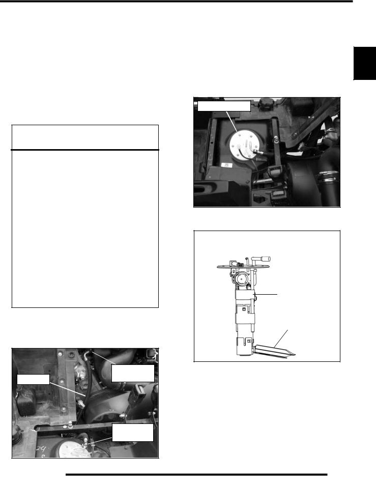
Fuel Pump / Fuel Filters |
2 |
The 800 EFI RZR engine uses a non-serviceable, high-volume, |
|
high-pressure, fuel pump that includes a preliminary filter and |
|
an internal fine filter located before the pump regulator. |
|
Fuel Pump Asm |
|
NOTE: Neither filter is servicable.
Fuel Pump Asm
Located in Fuel Tank
Fine Filter
Preliminary Filter
|
Injector Rail |
Fuel Line |
Connector |
Fuel Pump
Connector
NOTE: For all other information related to the EFI System, refer to Chapter 4.
Vent Lines
1.Check fuel tank, front gear case, rear gear case and transmission vent lines for signs of wear, deterioration, damage or leakage. Replace every two years.
2.Be sure vent lines are routed properly and secured with cable ties.
IMPORTANT: Ensure lines are not kinked or pinched.
2.11
MAINTENANCE
Throttle Pedal Inspection
If the throttle pedal has excessive play due to cable stretch or cable misadjustment, it will cause a delay in throttle speed. Also, the throttle may not open fully. If the throttle pedal has no play, the throttle may be hard to control, and the idle speed may be erratic.
Throttle Pedal
Check the throttle pedal play periodically in accordance with the Periodic Maintenance Chart and adjust the play if necessary.
Throttle Freeplay Adjustment
Inspection
1.Place the transmission in the P (Park) position.
2.Start the engine, and warm it up thoroughly.
3.Measure the distance the throttle pedal moves before the engine begins to pick up speed. Freeplay should be 1/16” - 1/8” (1.5 - 3 mm).
Adjustment
1.Remove both seats and rear service panel.
2.Locate the throttle cable adjuster at the throttle body.
Throttle Cable
Adjuster
3.Slide back the cable adjuster boot.
4.Using a 10 mm open-end wrench, loosen the adjustment jam nut.
5.Using an 8 mm open-end wrench, move the cable adjuster until 1/16” to 1/8” (1.5 - 3 mm) of freeplay is achieved at the throttle pedal.
Throttle Body
Adjuster
Boot
Jam Nut
NOTE: While adjusting, lightly move the throttle pedal in and out.
6.Re-tighten the jam nut.
7.Apply a small amount of grease to the inside of the boot and slide it over the cable adjuster to its original position.
Throttle Cable Replacement
1.Place the vehicle in PARK and stop the engine.
2.Remove the seats and rear service panel (see Chapter 5).
3.Remove the shift handle knob and center console (see Chapter 5).
4.Remove the rear cargo box and rear bumper as an assembly (see Chapter 5).
5.Remove the air intake box (see “Air Filter Service”).
6.Remove both PVT outlet and inlet ducts to allow access the throttle body cover (see Chapter 6).
7.Remove the throttle body cover.
NOTE: Upon removing the cable from the throttle plate arm, the brass retainer will become loose or separated from the cable. Take care not to drop brass retainer upon removal.
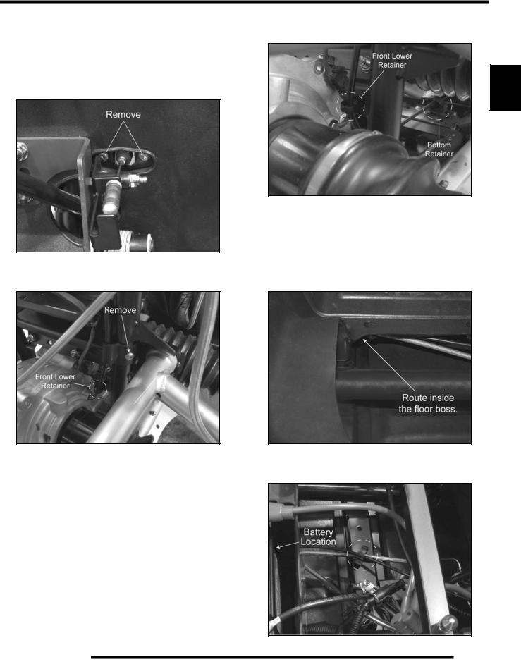
8.Pull back on the throttle plate arm and remove the throttle cable.
9.Using an 8 mm open-end wrench, remove the throttle cable from the throttle body.
10.Remove the rear floor and rocker panel fasteners to loosen the floor.
2.12
MAINTENANCE
11.Lift up on the floor and remove the panduit strap retaining the throttle cable and brake line to the frame.
12.Remove the cable end and retainer from the throttle foot pedal.
13.Remove the (2) screws retaining the throttle cable bracket to the frame support.
20.Route the cable through the retainer at the bottom of the frame in the floor console opening.
2 |
14.Remove the front upper cable clamp from the vertical frame tube.
21.Continue to route the cable towards the rear of the vehicle following the brake line routing.
22.Use the (2) cable ties to retain the throttle cable to the brake line.
NOTE: Be sure to route the throttle cable inside the boss on the rear portion of the floor.
15.Push the rear tabs together and remove the front lower cable retainer.
16.Pull the throttle cable out through the front left wheel well and discard the cable.
17.Install the new cable into the vehicle through the front left wheel well. Route the cable over the upper A-arm and between the front left-hand drive shaft and frame, and between the front gearcase and frame.
18.Install the front upper cable clamp making sure to allow enough cable slack to attach the cable bracket to the frame support.
19.Open the front lower cable retainer, place over the cable and reinstall retainer into the frame hole.
23.Insert the rosebud retainer as shown and route the throttle cable and brake line through the retainer.
2.13

MAINTENANCE
24.Route the cable around the circumference of the PVT cover up and over to the throttle body.
25.Apply pipe sealant or PTFE Teflon® tape to the threads at the end of the throttle cable.
NOTE: If using a liquid sealant, do not allow sealant to contact the internal throttle cable.
26.Screw the throttle cable end into the throttle body.
27.Pull back on the throttle plate arm and insert the throttle cable and brass bushing. Pull slack out of the cable at the foot pedal end to ensure it stays in place.
28.Move to the front of the vehicle and route the upper portion of the cable inside of the brake line.
29.From the left side of the vehicle, hold and align the throttle cable bracket to the frame support with your left hand. Reach into the footwell area with your right hand and start the screws. NOTE: May require an assistant.
30.Torque the retaining screws to 50 in. lbs. (5.6 Nm).
31.Install the cable end and retainer into the throttle foot pedal.
32.Move back to the throttle body and check to see that the throttle plate arm is resting against the stop. If not, turn in the cable adjuster in (clockwise) until the throttle plate arm rests on the stop.
33.Install the throttle body cover and PVT inlet duct.
34.Verify the vehicle is still in PARK.
35.Start the engine and allow it to warm up.
36.Measure the distance the throttle pedal moves before the engine begins to pick up speed. Freeplay should be 1/16" - 1/8" (1.5 - 3 mm).
•If freeplay is correct, proceed to next step.
•If adjustment is required, refer to “Throttle Freeplay Adjustment” procedure.
37.Using a 10 mm open-end wrench, tighten the jam nut against the throttle body housing. Torque jam nut to 45 in. lbs. (5 Nm).
38.Apply a small amount of grease to the inside of the boot and slide it over the cable adjuster.
39.Reassemble the vehicle using the appropriate areas of the Service Manual as a reference if needed.
40.After reassembly, field test unit to ensure proper throttle operation.
Air Filter Service
It is recommended that the air filter be inspected as part of pre-ride inspection. When riding in extremely dusty conditions, apply grease to the seal under the air box cap. In extremely dusty conditions, air filter replacement will be required more often.
The filter should be inspected using the following procedure.
Removal
1.The air box is located just above the rear LH wheel in the wheel well area.
2.Unlatch the (3) clips and remove the air box cap. Inspect the seal. It should adhere tightly to the cover and seal all the way around.
Air Box Location
3.Remove air filter assembly and remove the pre-filter sleeve.
2.14
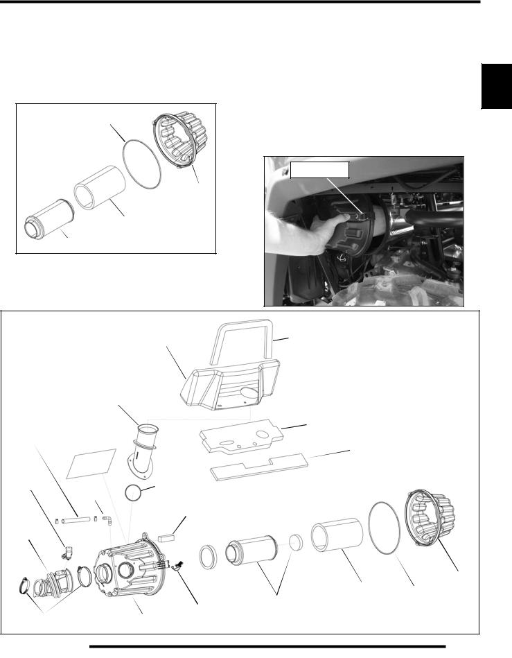
MAINTENANCE
4.Inspect the main air filter element and replace if necessary. Do not clean the main filter, the filter should be replaced.
NOTE: If the filter has been soaked with fuel or oil it must be replaced.
5. Wash pre-filter in warm soapy water and allow it to air dry.
NOTE: If unable to clean the pre-filter, replace it.
Seal
Cap
Pre-Filter
Sleeve
Air Filter
NOTE: Service more frequently if vehicle is operated in wet conditions or at high throttle openings for extended periods.
Installation |
|
|
1. |
Clean the air box thoroughly. |
|
2. |
Install a new or clean pre-filter over the main air filter |
|
|
element. |
|
3. |
Place filter ring over the end of the filter and install the filter |
2 |
|
into the air box. Be sure the filter fits tightly in the air box. |
|
NOTE: Apply a small amount of general purpose |
|
|
grease to the sealing edges of the filter and the air |
|
|
box cap seal before installing. |
|
|
4. |
Install air box cap and secure with clips. |
|
|
Secure Clips |
|
|
Front |
Intake Box |
Foam Seal |
|
Air Intake Duct |
|
Foil |
|
Primary |
Breather |
|
Foam Seal |
|
|
|
Hose |
|
Intake Seal |
|
|
|
T-MAP |
|
|
Sensor |
Fitting |
Seal |
|
Breather |
|
|
|
|
|
|
Filter |
Boot |
|
|
Cap
|
Pre-Filter |
Seal |
Air Filter |
Sleeve |
|
Clip (3)
Clamps |
Air Box Can |
Filter Ring |
2.15

MAINTENANCE
ENGINE
Engine Oil Level
The twin cylinder engine is a wet-sump engine, meaning the oil is contained in the bottom of the crankcase. To check the oil level follow the procedure listed below.
Dipstick
1.Position vehicle on a level surface.
2.Place the transmission in PARK (P).
3.Be sure the machine has sat for awhile before removing the dipstick.
IMPORTANT: Do not run the machine and then check the dipstick.
4.Remove both seats and the rear service panel.
5.Stop engine and lift the lever lock. Remove dipstick and wipe dry with a clean cloth.
Dipstick
Lever Lock
Lever Lock
Dipstick
SAFE |
ADD 8 OZ |
6.Reinstall the dipstick completely, but do not lock it.
NOTE: Make certain the dipstick is inserted all the way into the filler tube to keep the angle and depth of dipstick consistent.
7.Remove the dipstick and check the oil level. Maintain the oil level in the “SAFE” range. Add oil as indicated by the level on the dipstick. Do not overfill (see NOTE below).
NOTE: Due to the dipstick entry angle into the crankcase, the oil level will read higher on the bottom side of the dipstick. Proper level indication is determined on the upper surface of the dipstick as it is being removed, regardless of the level marks being on top or on bottom (see the next illustration).
Dipstick
Always read top side of dipstick to properly check oil level in crankcase
NOTE: A rising oil level between checks in cool weather driving can indicate contaminants such as gas or moisture collecting in the crankcase. If the oil level is over the full mark, change the oil immediately.
8.Reinstall the dipstick and seat the lever lock.
2.16

MAINTENANCE
Engine Oil and Filter Service
Always change engine oil and filter at the intervals outlined in the Periodic Maintenance Chart. Always change the oil filter whenever changing the engine oil.
 WARNING
Personal injury can occur when handling used oil. Hot oil can cause burns or skin damage.
Recommended Engine Oil:
PS-4 PLUS 2W-50 Synthetic 4-Cycle
Engine Oil (PN 2876244) (Quart)
Ambient Temperature Range
-40° F to 120° F
1.Position vehicle on a level surface.
2.Place the transmission in PARK (P).
3.Start the engine. Allow it to idle for two to three minutes until warm. Stop the engine.
4.Clean area around oil drain plug at bottom of engine.
NOTE: Drain plug is accessed through the skid plate.
Drain Plug |
 CAUTION
Oil may be hot. Do not allow hot oil to come into contact with skin, as serious burns may result.
5.Place a drain pan beneath engine crankcase and remove the drain plug.
6.Allow oil to drain completely.
7.Replace the sealing washer on drain plug.
NOTE: The sealing surface on the drain plug should be clean and free of burrs, nicks or scratches.
8. |
Reinstall drain plug and torque to 16 ft. lbs. (22 Nm). |
|
|
9. |
Remove both seats and rear service panel. |
|
|
10. |
Place shop towels beneath oil filter. |
Using Oil Filter |
2 |
|
Wrench (PV-43527) and a 3/8” extension, turn the oil filter |
||
|
counter-clockwise to remove it. |
|
|
Oil Filter |
11.Using a clean dry cloth, clean filter sealing surface on the crankcase.
12.Lubricate O-ring on new filter with a film of fresh engine oil. Check to make sure the O-ring is in good condition.
13.Install new filter and turn by hand until filter gasket contacts the sealing surface, then turn an additional 1/2 turn.
14.Remove dipstick and fill sump with 2 quarts (1.9 l) of PS-4 PLUS 2W-50 Synthetic Engine Oil (PN 2876244).
Crankcase Drain Plug Torque:
16 ft. lbs. (22 Nm)
Oil Filter Torque:
Turn by hand until filter gasket contacts sealing surface, then turn an additional 1/2 turn
Oil Filter Wrench:
(PV-43527)
15.Verify the transmission is still positioned in PARK (P).
16.Start the engine and let it idle for one to two minutes.
17.Stop the engine and inspect for leaks.
18.Re-check the oil level on the dipstick and add oil as necessary to bring the level to the upper mark on the dipstick.
19.Dispose of used oil and oil filter properly.
2.17
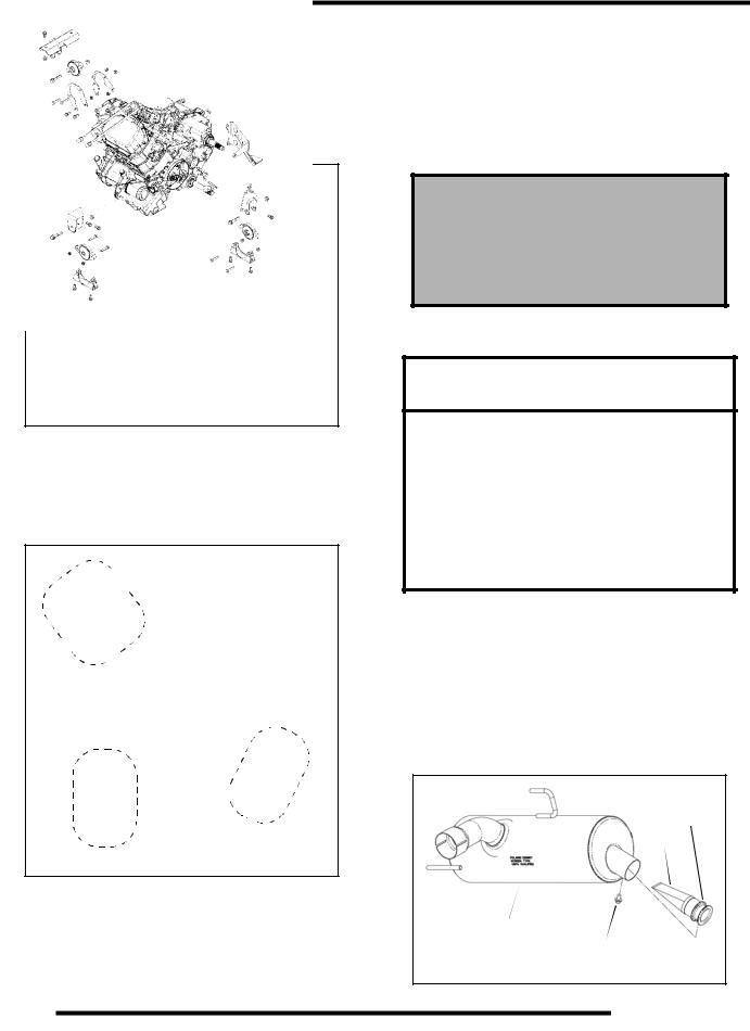
MAINTENANCE
Engine Breather Hose Inspection
The engine is equipped with a breather hose. Inspect the breather hose for possible kinks or wear. The hose is form fitted for a proper fit. Follow the breather hose from the side of the airbox to the engine valve cover.
Breather
Hose 
NOTE: Make sure line is not kinked or pinched.
Engine and Transmission Mount Locations
Periodically inspect engine and transmission mounts for cracks or damage.
 Rear Mount
LH Mount
RH Mount
Compression and Leakdown Test
NOTE: This engine does NOT have decompression components. Compression readings will vary in proportion to cranking speed during the test.
A smooth idle generally indicates good compression. Low engine compression is rarely a factor in running condition problems above idle speed.
A cylinder leakdown test is the best indication of engine condition. Follow manufacturer's instructions to perform a cylinder leakage test (never use high pressure leakage testers, as crankshaft seals may dislodge and leak).
Cylinder Compression 800: 150-170 PSI 800 HO: 165-185 PSI
Cylinder Leakdown
Service Limit 15%
(Inspect for cause if test exceeds 15%)
Exhaust - Spark Arrestor
 WARNING
Do not clean spark arrestor immediately after the engine has been run, as the exhaust system becomes very hot. Serious burns could result from contact with the exhaust components. Allow components to cool sufficiently before proceeding. Wear eye protection and gloves.
Never run the engine in an enclosed area. Exhaust contains poisonous carbon monoxide gas that can cause loss of consciousness or death in a very short time.
Periodically clean spark arrestor to remove accumulated carbon.
1.Remove the retaining screw and remove the arrestor from the end of the silencer.
2.Use a non-synthetic brush to clean the arrestor screen. A synthetic brush may melt if components are warm.
3.Inspect the screen for wear and damage. Replace if needed.
4.Reinstall the arrestor and torque the screw to 40 in. lbs. (4.5 Nm).
Arrestor
Screen
Silencer
Retaining
Screw
2.18
 Loading...