

Page 1
Printing System
im3510/4510
Operating Guide
Page 2

Warranty
While every effort has been made to make this document as accurate
and helpful as possible, PBC makes no warranty of any kind with
regard to its content. All information included herein is subject
to change without notice. PBC is not responsible for any loss or
damages, direct or indirect, arising from or related to the use of this
operation manual.
© Copyright PBC. All rights reserved. Reproduction, adaptation or
translation without prior written permission is prohibited, except as
allowed under copyright laws.
Trademark Acknowledgments
Microsoft Windows, MS-DOS, and Windows NT are trademarks of
Microsoft Corporation in the U.S.A. and other countries.
Macintosh, Power Macintosh, Mac OS, LaserWriter, and AppleTalk
are registered trademarks of Apple Computer, Inc.
IBM, PC/AT, and PowerPC are trademarks of International Business
Machines Corporation.
Pentium is a registered trademark of Intel Corporation.
PCL is a trademark of the Hewlett-Packard Company.
PostScript® is a registered trademark of Adobe Systems
Incorporated.
NetWare is a registered trademark of Novell, Inc.
All other trademarks and copyrights are the property of their
respective owners.
Page 3

im3510/4510 Printing System
...............................................................
....
...............................................................
........
.................
.................................
Speci cations of paper trays
Setting the paper size and type
..............................
Speci cations (multi purpose drawer)
paper drawer
Speci cations (stand/3 x 500 sheet
paper drawer)
..........................................................
sheet paper drawer
Speci cations (stand/3 x 500 sheet paper drawer)
Adding Toner
Storage of Supplies
................................................
2-2
Software for Windows
2-3
2-3
.........................................................
2-4
Setting the Printer Driver
.................................................
2-5
and setting print conditions)
2-5
....................
2-6
......
2-6
Accessing Web pages and displaying help
2-6
......
2-7
Job Control
...............................................................
.........
2-9
.............................................................
2-10
...........................................
2-12
2-13
.....
2-13
...
2-15
...........................................
3-2
........................................................
3-2
.........................................................
3-4
3-5
....................................................
3-5
...............................................................
.
3-6
.....
3-6
Setting items
.............................................................
3-8
Troubleshooting and Maintenance
...............................................................
4-2
........................
4-2
4-3
.................................
4-4
.......................
4-5
Operating Guide
Table of Contents
Page 4

im3510/4510 Printing System
and exit area
.............................................................
4-6
...............................................................
.
4-8
...........................................................
4-11
...............................................................
...
Speci cations
............................................................
..............................
Setting the printer driver for duplex module,
bypass tray and exit tray
...........................................
......................................
...............................................................
..............
Supplies
...............................................................
......
Speci cations
............................................................
....................................................
Staple cartridge replacement
...................................
............................................
Stapling position quick reference guide
.....................................................
Saddle Stitch Finisher
..............................................................
Speci cations
..........................................................
Saddle stitch nisher functions
..............................
.......................
saddle stitch nisher)
.............................................
Stapling position quick reference guide
....
Appendix
..................
.......................
...............................................................
...........
.........................................
.............................
..........................................
...............................................................
.
Operating Guide
Table of Contents
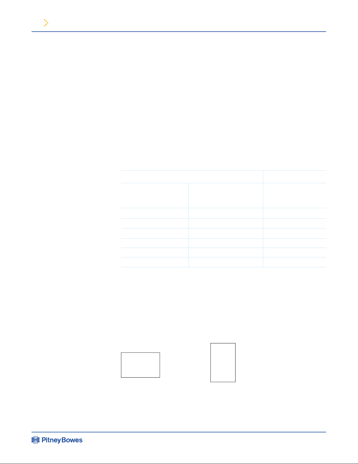
Page 5
The machine should be installed
the speci ed voltage and current
that are:
poorly ventilated
temperature or humidity
4.
space around the machine for
servicing and proper ventilation.
Installation Requirements
31-1/2"
(80cm)
23-5/8"
(60cm)
23-5/8" (60cm)
11-13/16" (30cm)
im3510/4510 Printing System Operating Guide
A small amount of ozone is produced
within the printer during operation. The
emission level is insuf cient to cause
any health hazard.
NOTE: The present recommended long
term exposure limit for ozone is 0.1
ppm (0.2 mg/m3) calculated as an 8 hr.
time-weighted average concentration.
However, since the small amount that
is emitted may have an objectionable
odor, it is advisable to place the copier
in a ventilated area.
Page 1
Page 6
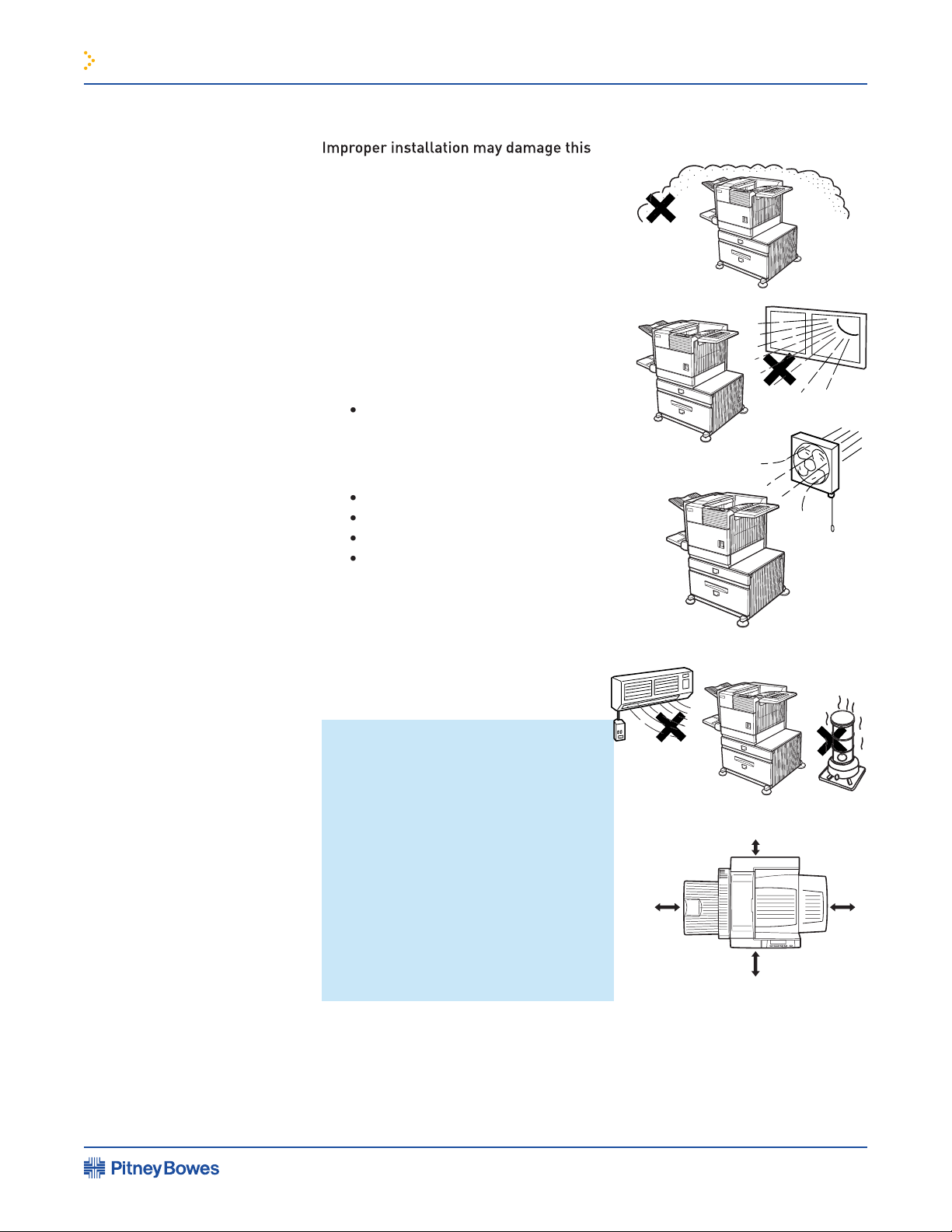
Installation Requirements
The stand/paper drawer is equipped with casters for moving. Unlock the adjusters
prevent it from toppling.
Remove the multi
purpose drawer
in advance.
Ventilating holes
im3510/4510 Printing System Operating Guide
Moving this Machine
CAUTION
Two people are required to lift and carry this machine.
The center of gravity of the machine is slightly to the left of the center of
the machine when viewed from the front. If a duplex module is installed the
center of gravity will be even further shifted to the left. When lifting
the machine be careful to steady it to prevent it from toppling. Also be sure
that all covers and the duplex module are securely closed and latched
before lifting.
If a duplex module is installed, do not lift the machine by the module as it
may come off causing it and the machine to drop.
CAUTIONS
• The center of gravity of this machine is a little deviated to the left from the
center. If the machine is not equipped with a multi purpose drawer or a
stand/paper drawer, take care in opening the left side cover (or the duplex
module) not to cause toppling of the machine.
• Do not cover the ventilating holes of this machine. Do not install this
machine in a location where these holes are covered. If these holes are
covered, heat will not be dissipated and a re may be caused.
Page 2
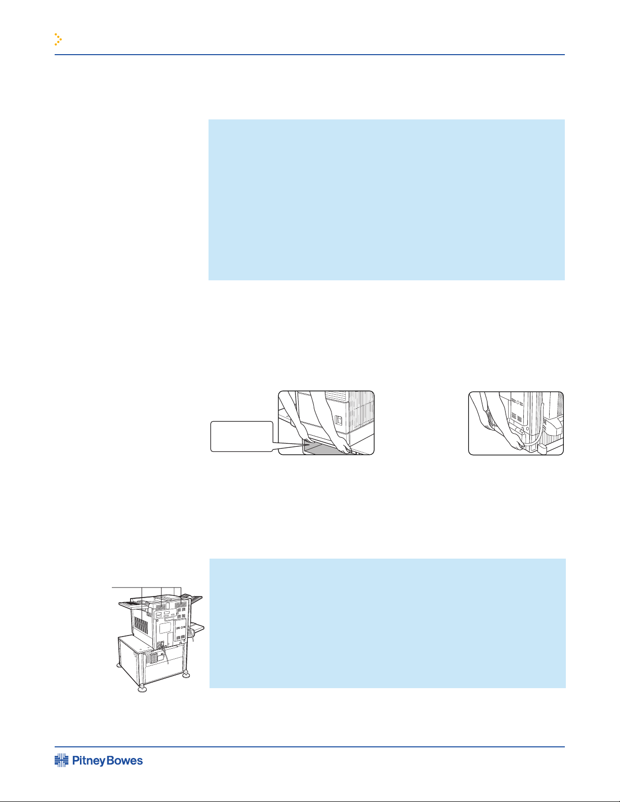
Page 7

The fusing unit is extremely hot. Exercise
the scanner module. Doing so may damage
your eyes.
These adjusters should be lowered
until they contact the oor.
than one person to prevent injury.
When connecting this machine to a
from printing by law. The following items
federal law. Other items may be prohibited
by municipal law.
Fusing unit
Adjuster
Lock Release
Cautions
im3510/4510 Printing System Operating Guide
Moving this Machine
continued
Page 3
“BATTERY DISPOSAL”: THIS MACHINE CONTAINS A LITHIUM BATTERY
WHICH MUST BE DISPOSED OF PROPERLY. CONTACT YOUR PB SERVICE
REPRESENTATIVE FOR INSTRUCTIONS.
This product utilizes tin-lead solder, and a uorescent lamp containing a
small amount of mercury. Disposal of these materials may be regulated
due to environmental considerations. For disposal or recycling information,
please contact your local PB service representative.
Page 8

Wave length
45 cpm model: (5.7 µs ± 5.7 ns)/7 mm
45 cpm model:
This Digital Equipment is rated Class 1 and complies with 21 CFR 1040.10
produce hazardous laser radiation. For your safety, observe the precautions below.
The equipment’s exterior covers contain several safety interlock switches.
Cautions
im3510/4510 Printing System Operating Guide
Cautions on laser
NOTE: At the production line, the output power of the scanner unit is
adjusted to 0.4 MILLIWATT PLUS 8 % and is maintained constant by the
operation of the Automatic Power Control (APC).
CAUTION: This product contains a low power laser device. To ensure safety
do not remove any cover or attempt to gain access to the inside of the
product. Refer all servicing to quali ed personnel.
Safety Precautions
CAUTION: Use of controls or adjustments or performance of
procedures other than those speci ed herein may result in hazardous
radiation exposure.
Page 4
Page 9
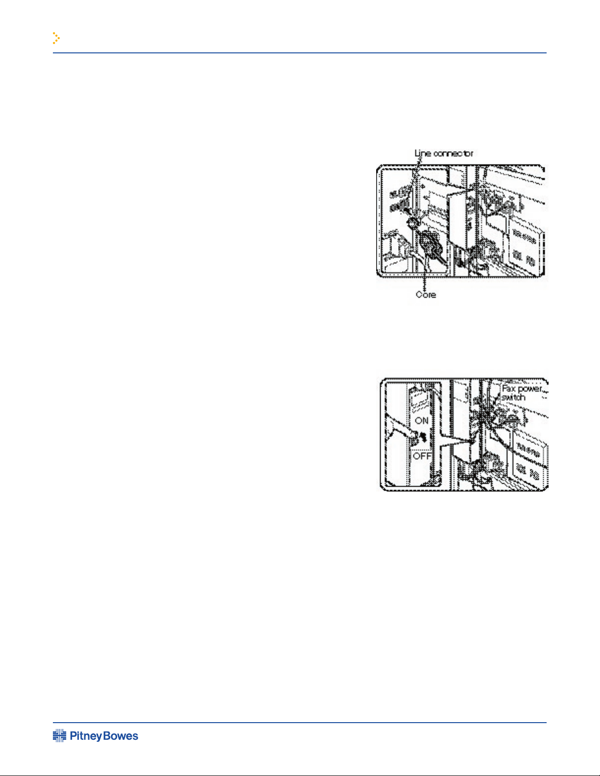
To extend the capabilities of this product to include facsimile functions,
Use the telephone cable supplied
with the facsimile expansion kit to
line. Connect the cable so that
the connector nearest to the noise
the socket located of the expansion
kit box. Insert the other end into
the telephone line socket.
function, the power switch
located on the expansion kit box
Facsimile Feature
im3510/4510 Printing System Operating Guide
Line connection
Fax power switch
Page 5
Page 10

Introduction
...............................................................
.....
Main Features
...............................................................
..
Part Names and Functions
Exterior
...............................................................
....
Interior
...............................................................
.....
Part names and functions of peripheral devices
............................
................
Loading Paper
...............................................................
Loading paper in paper tray 1
...............................
Speci cations of paper trays
.................................
Setting the paper size and type
.............................
Loading paper in the multi purpose drawer
Speci cations (multi purpose drawer)
.................
Loading paper in the stand/3 x 500 sheet
paper drawer
Speci cations (stand/3 x 500 sheet
paper drawer)
.......................................................
Loading paper in the stand/MPD & 2000 sheet
paper drawer
........................................................
Speci cations (stand/3 x 500 sheet
paper drawer)
Adding Toner
...............................................................
..
Storage of Supplies
......................................................
This chapter describes basic information that should be
1 Before using the Product
im3510/4510 Printing System Operating Guide
Chapter Contents
Page 11
1 Before Using the Product
To gain the maximum bene ts in using this product, it is recommended that the user
This product is a high speed laser printer that can be extended to become multifunctional
through the installation of optional peripheral devices. The product can be extended to
include copier, network scanning, facsimile or network printing capabilities. This manual
for any of the optional peripheral devices. Separate operation manuals are included with
This machine allows use of standard sizes in both the inch and AB systems. The standard
Sizes in the inch system
Sizes in the AB system
When the machine is being
When the machine is being
A3
A5
A4R, B5R, etc. Sizes that can be placed only in the landscape orientation
Size indication with “R”
Size indication without “R”
im3510/4510 Printing System Operating Guide
Introduction
Original and paper sizes
The meaning of “R” in original and paper size indications
Page 1-2
Page 12

1 Before Using the Product
This product is a laser printer that can be used as a local printer which can be con gured
by the addition of peripheral devices to extend its capabilities to include copier, network
printer, network scanner or facsimile features.
feed units to increase the variety of available paper sizes and paper capacity, paper output
units to sort and otherwise organize the output and a scanner module for automatically
high image quality equivalent to 1200 dpi can be output by using a smoothing function.
This product has the following two power reducing modes that conform to the
The preheat mode is the rst level of power reduction. The power is reduced to the
fuser unit a preset time after the machine has completed a job and no further machine
period of time. The preset time to enter the mode can be set by a key operator program.
The auto power shut-off mode is the second level of power reduction. In this mode power
is shut off to the fusing unit and the touch panel. In this state more energy is saved than in
the preheat mode but the time to recover to the ready condition will be longer. The preset
time to enter this mode can be set by a key operator program.
When this product is used as a printer, and either of the above modes is active, the mode
will be deactivated automatically by an incoming job and the machine will automatically
warm up and start to print when it has reached the ready temperature.
When this product is con gured for multi-function operation, and either of the
print job or received facsimile data. Either mode will also be deactivated by any key
As an ENERGY STAR
®
product meets the
guidelines
for energy ef ciency.
im3510/4510 Printing System Operating Guide
Main Features
Energy Saving Features
Laser printer able to accept a range of peripherals allowing it to be con gured to
speci c needs
A range of optional units to enhance productivity
600 dpi high resolution printing
High speed monochrome printing
Preheat mode
Auto power shut-off mode
Page 1-3
Page 13

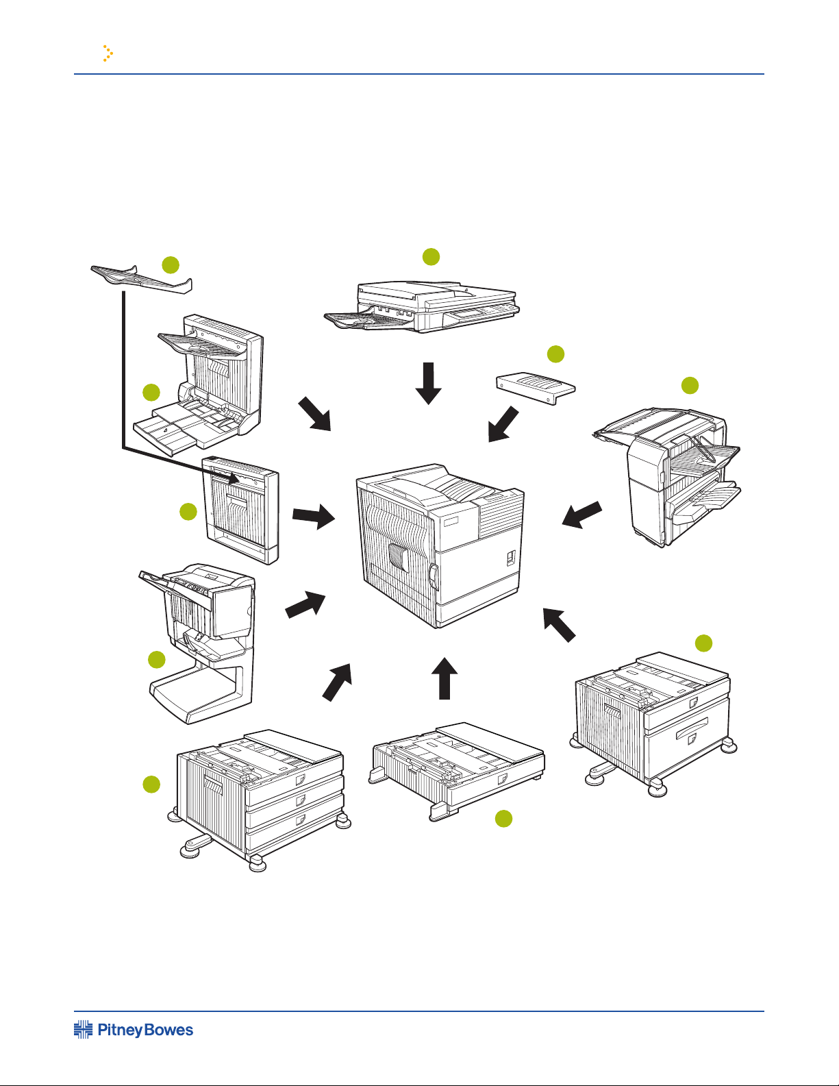
1 Before Using the Product
Module for two-sided printing
4.
(See page 1-9.)
Stand/3 x 500 sheet paper drawer*
(See page 1-23.)
Stand/MPD & 2000 sheet paper drawer*
(See page 1-24.)
im3510/4510 Printing System Operating Guide
Part Names and Functions
Exterior
1 2
4 5
3
7 8 9 10
6
11
12
Page 1-4
Page 14

1 Before Using the Product
Side cover latch
This cartridge contains developer and must be removed and replaced by a new
Toner cartridge (drum/toner cartridge)*
The toner cartridge must be replaced when indicated on the operation panel.
When replacing the drum, toner or developer cartridge, turn down this lever and
pull it out.
im3510/4510 Printing System Operating Guide
Part Names and Functions
continued
Interior
13 14 15 16 17
18 19
CAUTION: The fusing unit is hot. Take care in removing misfed paper.
NOTE: Do not touch or damage the photoconductive drum.
Page 1-5
Page 15
1 Before Using the Product
im3510/4510 Printing System Operating Guide
Part Names and Functions
continued
10
9
8
Part names and functions of peripheral devices
1
2
3
4
7
6
5
Page 1-6
Page 16

1 Before Using the Product
This unit is a monochrome scanner that uses two
moving originals. In this mode either one side of an original can be scanned or both
Mount this unit to the upper paper exit tray. This
page. Sorted sets or groups are offset stacked for easy separation when removed.
Stand/MPD & 2000 sheet paper drawer (9248) -
This paper feed unit contains an
upper multi-purpose drawer (see item ) and a lower drawer which can hold a maximum
Up to 500 sheets of 20 lbs. (80 g/m2) paper can be loaded.
Also special papers such as envelopes (standard sizes only) and postcards can be set.
Stand/3 x 500 sheet paper drawer -
This paper feed unit contains an upper multi-
purpose drawer (see item ) and two lower drawers each of which can hold a maximum
Saddle stitch nisher (9254) -
The saddle stitch nisher can automatically place two
An optional hole punching unit is available for installation into the nisher.
An optional duplex module must be installed for automatic
two-sided printing.
This module is basically the same as above with
the addition of a manual bypass paper feed unit.
Mounted to the paper output port of a duplex module.
im3510/4510 Printing System Operating Guide
Part names and functions
of peripheral devices
continued
Some peripheral devices cannot be installed together while others may require
the installation of one or more others to be functional. See page 6-4, “LIST OF
COMBINATION OF PERIPHERAL DEVICES.”
Peripheral devices are basically optional, but some are provided as standard
equipment for some models.
Page 1-7
Page 17

1 Before Using the Product
Scanner rack (9241)
This rack is required to support the scanner module above the printer.
A NIC (network interface card) is necessary for connecting the printer to a network.
This print controller is necessary to provide copier, facsimile and network
This kit provides compatibility of PostScript level 3 to the printer.
required for the job retention function (see page 2-9) to operate.
This kit is required to add facsimile features.
Additional fax memory (8 MB) (ZB3500060)
This kit is required to add the network scanning feature.
im3510/4510 Printing System Operating Guide
Part names and functions
of peripheral devices
continued
Other Optional Equipment
Page 1-8
Page 18
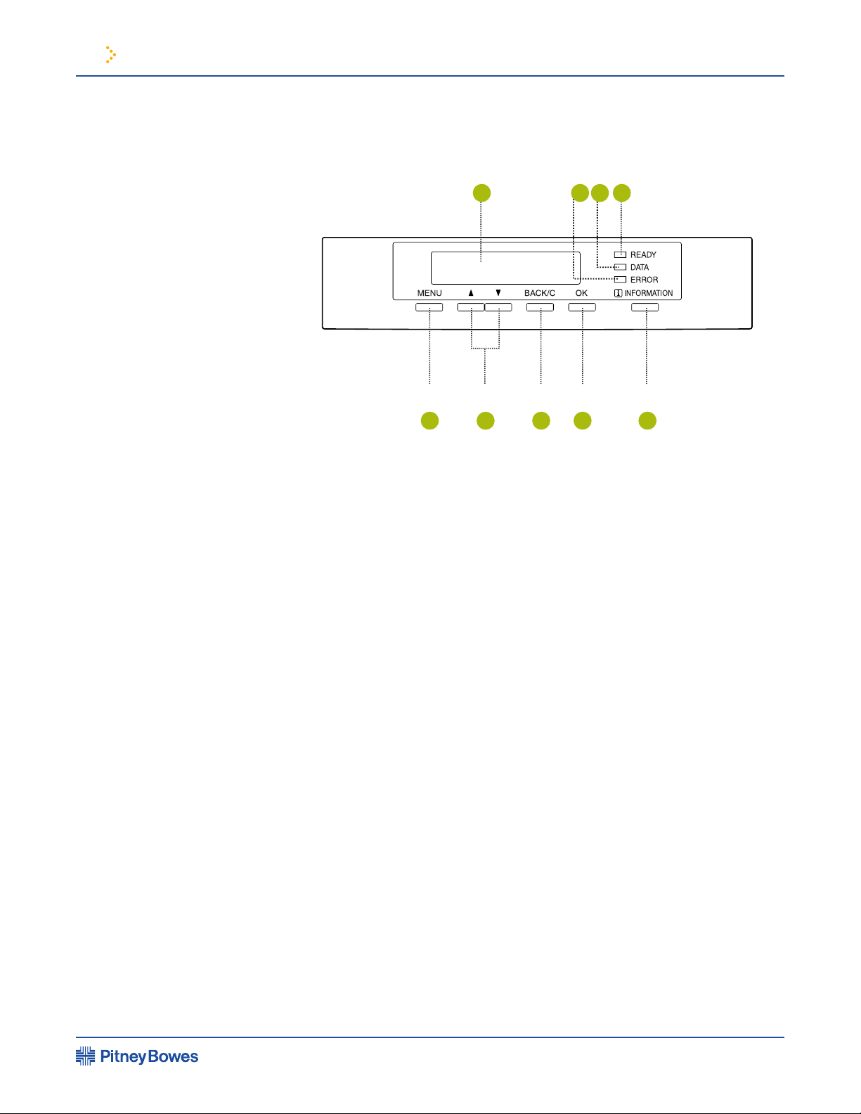
1 Before Using the Product
The display and indicators show the current status of the printer. All printer settings are
machine. Blinks when an abnormal condition has occurred in the machine.
job data is stored by the job retention function (page 2-9).
Use this key to return to the previous screen in each menu selection, to cancel and
When [ i ] is displayed with a message indicating a paper misfeed, the relevant
while printing is being performed or in standby, the total number of printed pages and
im3510/4510 Printing System Operating Guide
Operation Panel of the Main Unit
1 2
5
6
7 8 9
4
3
Page 1-9
Page 19
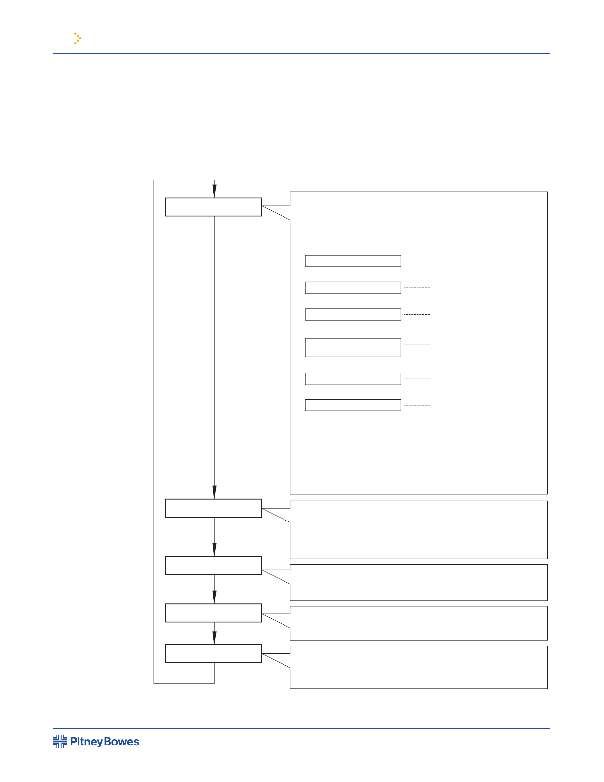
1 Before Using the Product
The menu groups are classi ed into ve groups and are selected consecutively by pressing
the [MENU] key. If the [OK] key is pressed when the desired menu screen is displayed, a
message will appear to indicate the next required operation.
PRINT JOBS ON HOLD
SET OPERATIONS
CONDITIONS
CUSTOM SETTINGS
KEY OPERATOR
PROGRAMS
Job status screen
The message "WARMING UP" will be displayed when the power is turned on
and a list of the current job plus reser ved jobs or a list of completed jobs will
be displayed on the job status screen. Examples of the various messages
which will be displa
yed are shown below.
(Display example)
[ADD PAPER]
When the status display shows [ADD
PAPER], paper is required to
complete a job in progress. In this case, printing of the job will be
suspended until the required paper is added or another paper is
selected (see "Setting the paper size and type" on page 1-19).
While a current job is suspended, the printer will print a reser
ved
job if paper is available from another source
for that job but will not
print any other jobs.
The printer is warming up.
The printer is ready to print.
The printer is currently printing.
Out of toner. Replace the toner
cartridge. See the separate
operation manual entitled
"Operation Manual (Read this
document before installing the
product.)".
A misfeed has occurred. (See
page 4-2.)
Out of paper. Load paper. (See
page 1-16.)
Print hold
If the job retention function is used from your computer, print data will
be stored in the printer as a hold job.
The job retention function can be used only if the printer is equipped
with a hard disk drive unit. (See page 2-9.)
Condition settings
The printer condition settings are used for basic printer settings. (See
page 3-2.)
Custom settings
Custom settings are used to make settings based on use patterns.
(See page 3-5.)
Key operator programs
These are settings used by key operators (administrators of this
product). For the use of these programs, see page 7-1.
[MENU] key
[MENU] key
[MENU] key
[MENU] key
[MENU] key
READY.
WARMING UP.
READY.
FROM TRAY #
CHANGE THE TONER
CARTRIDGE.
PAPER JAM.
ADD PAPER.*
*
im3510/4510 Printing System Operating Guide
Operation Panel
of the Main Unit
continued
Menu group and explanation of the use of the keys
on the main unit operation panel
Page 1-10
Page 20

1 Before Using the Product
To cancel a print job in progress and delete the print data:
To cancel deletion, press the [BACK/C] key. Printing will resume.
To delete print data of a reserved job (jobs stored in the printer):
printing, press the [] or [] key to display the desired data in the message display. If you
press the [BACK/C] key at this time, a con rmation message for deletion will appear. To
To cancel deletion, press the [BACK/C] key. Printing will resume.
im3510/4510 Printing System Operating Guide
Operation Panel
of the Main Unit
continued
Canceling a print job and deleting print data
Page 1-11
Page 21
1 Before Using the Product
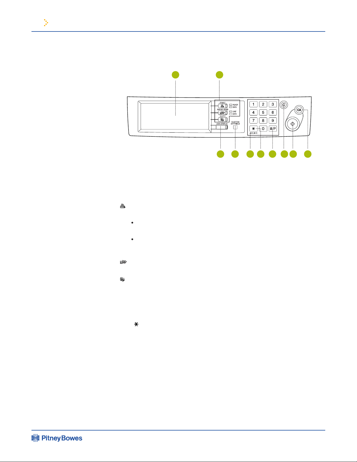
When the printer is equipped with a scanner module, the operation panel on the main
Touch panel - The machine status, messages and touch keys are displayed on the
panel. The display will change to show the status of print, copy, network scan or fax
Mode select keys and indicators - Use to switch the display mode of the touch panel.
Press to enter the print mode.
printing is being performed.
fax mode. (See the facsimile operation manual.)
Press to display the current job status. (See page 1-14.)
Use to adjust the contrast of the touch panel or to set key
Use to enter number values for various settings.
] key ([ACC.#-C] key) -
Use for account control for copying and fax sending.
This key is used as a program key for copy features and in dialing for fax
features.
This key is active for copy and fax features.
Start key* -
Use to start copying and fax jobs.
im3510/4510 Printing System Operating Guide
Operation panel of the scanner module
1 2
4 5
3
7 8 9 10
6
Page 1-12
Page 22
1 Before Using the Product
SELECT JOB.
PRINT HOLD JOB LIST
PB 005
PB 006
Microsoft Word - Test001
EXCEL1
1/1
CONDITION
SETTINGS
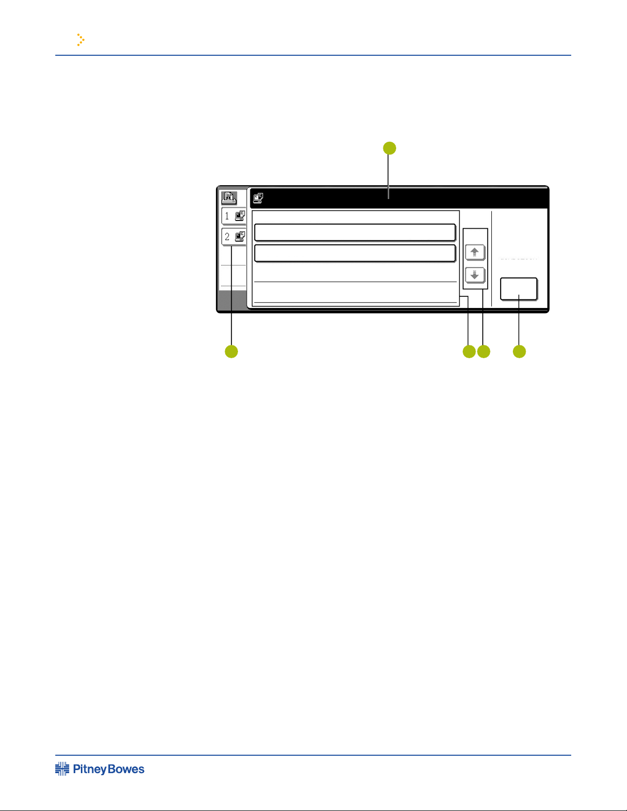
This screen is displayed when the print mode is selected.
Job status screen
(See next page.)
used only if the printer is equipped with a hard disk drive unit. If the main switch is
turned off, stored print data will be cleared.
4.
Use these keys to view the job hold list when it is contained on
more than one screen.
Use to switch the display to the printer con guration
menu (see page 3-2).
im3510/4510 Printing System Operating Guide
Touch panel (on the scanner module)
1
2
4 5
3
Page 1-13
Page 23
1 Before Using the Product
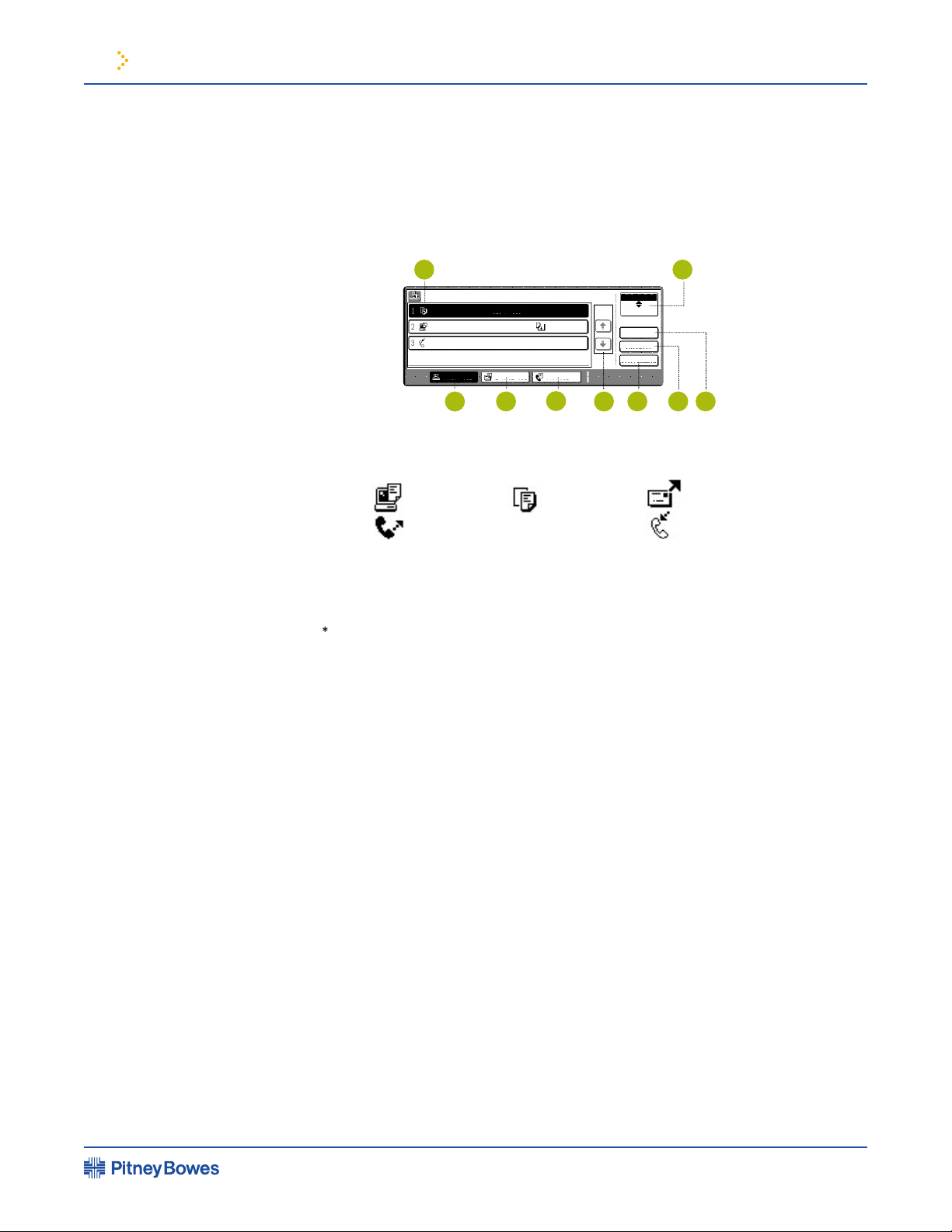
Job list -
A job list which indicates the current job and reserved jobs or a job list
which indicates completed jobs is displayed. The icons to the left of the jobs in queue
represent the job mode.
Network scan mode
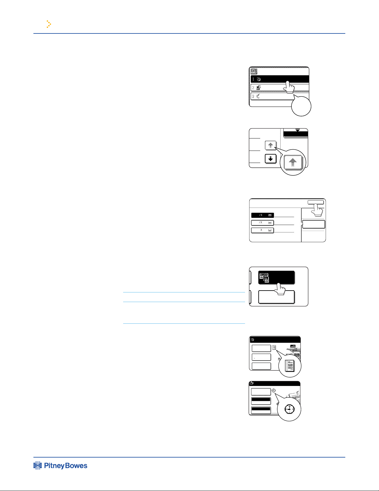
When a job list which indicates the current job and reserved jobs is displayed, the
highest print priority, touch the relevant job key to select the job and execute the
When a job status display indicates “PAPER
printing is suspended for that job until the required paper is loaded. Until the required
paper is loaded another reserved job data will be printed if possible. (If paper runs out
because you do not have the speci ed size paper, you can change the size by touching
the current job key to select it and touch the [DETAIL] key described in .
Use to switch the job list between “JOB QUEUE” and
Use to display the print job list for all modes (print, copy, network
4.
Use to display the list of jobs that use the network for sending
Use to display the fax communication status and the reserved
transmission job status.
Use to switch the page of the displayed job list.
Use to cancel or delete the current job or delete the selected reserved
job. Received fax print jobs that have been reserved, however, cannot be deleted.
list to which you wish to give the highest priority and touch this key, the job will move
to the highest priority reserved job.
Use to display the detailed information of the selected job. The paper
be used when a fax reception print job is selected.
Job status screen
(common to print, copy, network scan, and fax modes)
This screen is displayed when the [JOB STATUS] key on the operation panel is pressed.
A job list showing the current job at the top of the job queue or a list showing completed
jobs can be displayed. The contents of the jobs can be viewed, moved up to the highest
priority in the job queue or deleted from the queue.
JOB QUEUE
COPY
PB 001
054234
COPYING
PAPER EMPTY*
WAITING
STATUS
003 / 000
PRINT JOB E-MAIL/FTP FAX JOB
JOB QUEUE
COMPLETE
DETAIL
PRIORITY
STOP/DELETE
003 / 000
010 / 000
1/1
SETS / PROGRESS
im3510/4510 Printing System Operating Guide
Touch panel (on the
scanner module)
continued
1 2
3
4
5
6
7 8 9
Page 1-14
Page 24
1 Before Using the Product
by touching the key associ-ated with the
item with a nger. Selection of an item will
be accompanied with a beep tone to con rm
the item was selected. Also, the key area
for the item will be highlighted for visual
not selectable. If a grayed out key is touched,
The con rmation beeps can be disabled by a
key operator program. (See page 7-9.)
be registered to function if the [OK] key is
touched.
When the machine is used in the copy or fax
modes, the functions shown below can only
be set on the special feature screen. They can
be set or cancelled by alternate touches on
the panel.
When the machine is used in the copy or
fax modes and a special feature is selected, a
will appear on the touch key and on the main
touched, the setting screen of the function
function to be canceled easily.
JOB QUEUE
SETS / PR
PB 001 003 / 00
054234
COPY
010 / 00
003 / 00
Beep
tone
1/13
COMPLETE
010 / 000
WAITING
PLAIN
TRANSPARENCY
PLAIN
PAPER SELECT
OK
2.
1.
3.
11
17
11
8
1
2
11
8
1
2
MULTI SHOT
DUAL PAGE
COPY
SPECIAL MODES
2-SIDED COPY
OUTPUT
READY TO SCAN FOR COPY.
READY TO SEND.
SPECIAL MODES
RESOLUTION
ORIGINAL
AUTO
STANDARD
im3510/4510 Printing System Operating Guide
Touch panel (on the
scanner module)
continued
How to use the touch panel
Selection of function
Page 1-15
Page 25
1 Before Using the Product
The message “ADD PAPER” or “OPEN TRAY
AND ADD PAPER” will appear when paper
runs out during operation.
Set the paper type.
type referring to “Setting the paper size and type”
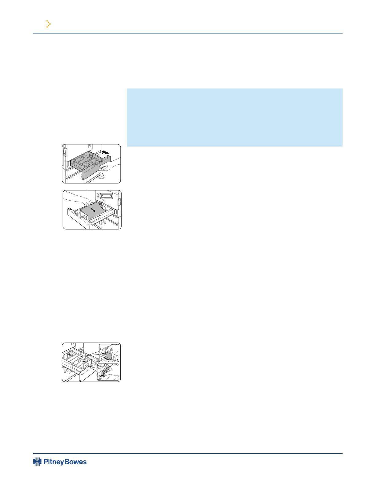
Adjust the guide plates A and B in the tray to the length and width of the paper.
The guide plates A and B are slidable. Adjust them to the aper size to be loaded while
Set the paper size -
the paper size and type” (page 1-19). If this is not done, paper misfeeds will occur.
to change the size as needed.
im3510/4510 Printing System Operating Guide
Loading Paper
NOTE:
• Do not use curled or folded paper. Doing so may cause a misfeed.
• For best results use paper supplied by PBC. (See page 1-18.)
• When you change the paper type and size in paper tray 1, set the paper
type and size referring to “Setting the paper size and type” (page 1-19).
• Do not place heavy objects or press hard on any tray which is pulled out.
Loading paper in paper tray 1
(1)
(2)
(2)
Changing the paper size in paper tray 1
Page 1-16
Page 26
1 Before Using the Product
The speci cations for types and sizes of paper for loading paper trays are shown below.
1
Tray
Tray
No.
(tray name)
Applicable paper types Applicable paper sizes
Paper
weight
Paper tray 1
Multi purpose
drawer/bypass tray
Tray
1
Tray
2/bypass tray
Tray
2 Same as multi purpose drawer
Plain paper (Refer to the next
page for applicable plain papers.)
Plain paper (Refer to the next
page for applicable plain papers.)
Plain paper (Refer to the next
page for applicable plain papers.)
Plain paper (Refer to the next
page for applicable plain papers.)
8-1/2 x 11, A4, B5
If "AUTO-INCH" is selected in setting the
paper size and type (page 1-19), the
following paper sizes can be used with the
automatic detection function:
11 x 17, 8-1/2 x 14, 8-1/2 x 11, 8-1/2 x 11R,
7-1/4 x 10-1/2R, 5-1/2 x 8-1/2R
If "AUTO-AB" is selected in setting the
paper size and type (page 1-19), the
following paper sizes can be used with the
automatic detection function:
A3, B4, A4, A4R, B5, B5R, A5R, 8-1/2 x 13
Non-standard siz
es
If "AUTO-INCH" is selected in setting the
paper size and type (page 1-19), the
following paper sizes can be used with the
automatic detection function:
11 x 17, 8-1/2 x 14, 8-1/2 x 11, 8-1/2 x 11R,
7-1/4 x 10-1/2R
If "AUTO-AB" is selected in setting the
paper size and type (page 1-19), the
following paper sizes can be used with the
automatic detection function:
A3, B4, A4, A4R, B5, B5R, 8-1/2 x 13
If "AUTO-INCH" is selected in setting the
paper size and type (page 1-19), the
following paper sizes can be used with the
automatic detection function:
8-1/2 x 11, 8-1/2 x 11R
If "AUTO-AB" is selected in setting the
paper size and type (page 1-19), the
following paper sizes can be used with the
automatic detection function:
A4, A4R, B5, B5R
Non-standard sizes smaller than 8-1/2 x 11
or A4
Japanese official postcard
Applicable standard size envelopes:
COM-10, Monarch, DL, C5, ISO B5
Non-standard siz
e
8-1/2 x 11, A4
16 to 28 lbs.
or 60 to 105
g/m
2
16 to 28 lbs.
or 60 to 105
g/m
2
16 to 28 lbs.
or 60 to 105
g/m
2
16 to 34 lbs.
or 60 to 128
g/m
2
See the
remarks for
special paper
on the next
page.
Special paper
(Refer to the
next page for
applicable
special
papers.)
Thick paper
Labels,
transparency
film
Postcard
Envelopes can
only be fed from
the multi-purpose
drawer.
Applicable paper
stock weight for
envelopes is 20
to 23 lbs. or 75 to
90 g/m
2
.
Stand/3 x
500 sheet
paper
drawer
Stand/
MPD &
2000
sheet
paper
drawer
Upper
Tray
2 Same as multi purpose drawer
Upper
Tray
3
Tray
3
Middle
Tray
4
Lower
Lower
im3510/4510 Printing System Operating Guide
Loading Paper
continued
Page 1-17
Speci cations of paper trays
Page 27
1 Before Using the Product
A5 to A3
the same conditions as above.
Type
Special paper
Thick paper
A4 sizes, thick paper ranging from 16 to
Transparency lm,
tracing paper
trouble.
weight for envelopes is 20 to 23 lbs. or
im3510/4510 Printing System Operating Guide
Loading Paper
continued
Applicable Plain Paper
Applicable Special Paper
Page 1-18
Page 28

1 Before Using the Product
When the [OK] key is pressed,“TRAY SETTING” will appear in the
message display.
When the [OK] key is pressed,the message
4.
Select the desired paper tray -
Press the or key repeatedly until the desired
paper tray is in dicated in the display.
The paper size and paper type of the tray
the message shown to the left will appear in the display.
If TRAY 1 is selected in step 4, the message
To cancel the setting change, press the [BACK/C] key to return
to step 4.
Select the paper type that has been set in the tray -
been set appears.
paper size appears.
When the paper system is changed from the inch system to the AB system or vise
versa, the paper type must be designated. Select the paper type.
When the paper size or type is changed in a paper tray, set them referring to the
following procedure.
TRAY SETTING
TRAY 1
CHANGE TRAY1
SETTING OK?
OK?
OK?
im3510/4510 Printing System Operating Guide
Loading Paper
continued
(1)
(2)
(4)
Setting the paper size and type
Setting the paper size and type from the
operation panel on the main printer
NOTE : Special paper such as thick paper, transparency lm, labels, and
postcards can be set for tray 2 and the bypass tray.
Envelopes can be set only for tray 2.
Page 1-19
Page 29
1 Before Using the Product
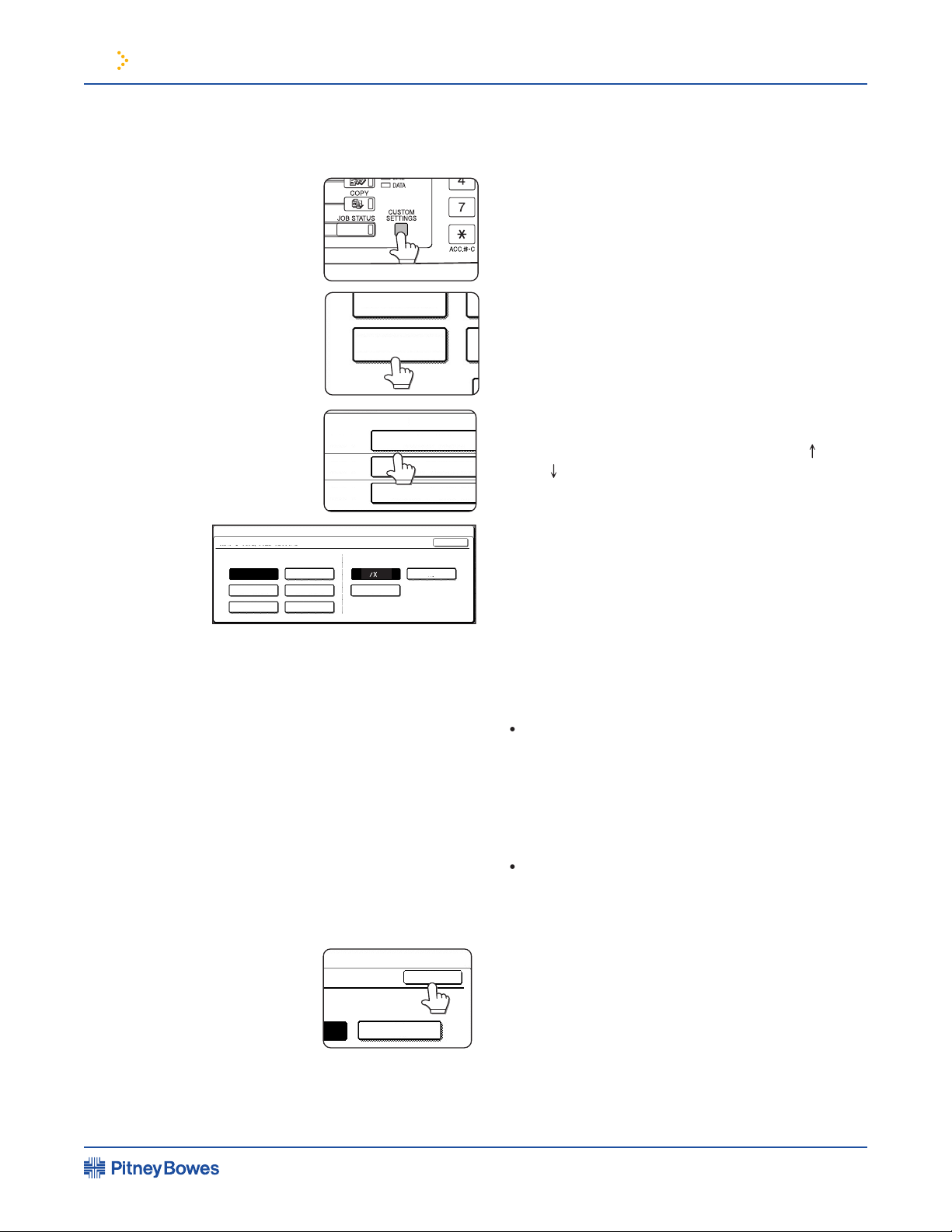
The custom setting menu screen will appear.
The paper tray selection screen will appear.
Select the paper tray for which the setting is
to be made.
4.
Select the paper type and the
The highlighted keys indicate the current selections.
To change either type or size or both, touch the
Special papers such as transparency lm
paper. When the paper system is changed from the
inch system to the AB system or vise versa, the paper
type must be designated. Select the paper type.
tray 2 or the bypass tray has been selected in step 3.
Touch the [OK] key to complete the setting.
TOTAL COUNT
TRAY SETTINGS
TRAY 1
TRAY 2
TRAY 3
PLAIN / AUTO-INCH
RECYCLED / AUTO-INCH
TYPE / SIZE
PLAIN / 8 X11
1
/
2
CUSTOM SETTINGS
TRAY 1 TYPE/SIZE SETTING
TYPE SIZE
LETTER HEAD
B5
PRE-PRINTED
RECYCLED COLOR
PRE-PUNCHED
OK
PLAIN
A4
11
8
1
2
SIZE
A4
OK
im3510/4510 Printing System Operating Guide
Loading Paper
continued
Setting the paper type and size from the touch panel
Page 1-20
Page 30

1 Before Using the Product
The method of loading paper into the multipurpose drawer is the same as for paper
tray 1 described on page 1-16.
transparency lm, follow the descriptions below.
Two maximum height lines are indicated: one for plain paper and one for special paper.
To change the paper size or paper type when paper is loaded into a tray, refer to page 1-19
for details.
When setting envelopes or postcards in the multi purpose drawer, set them in the
the rear left of the tray as shown.
Attempting to print onto both sides of envelopes or postcards may result in
misfeeds or poor prints.
To avoid wrinkling, misfeeds or poor printing, make sure the postcard
Maximum height line for plain paper
Do not exceed this line when loading plain paper.
Maximum height line for special paper (red line)
Do not exceed this line when loading special paper.
im3510/4510 Printing System Operating Guide
Loading Paper
continued
Loading paper in the multi purpose drawer
How to change the paper size
Setting envelopes or postcards
Printing onto envelopes or postcards
Page 1-21
Page 31

1 Before Using the Product
linings, self-adhesive patches or synthetic materials. Attempting to print on these may
become smudges.
Under high humidity and temperature conditions the glue aps on some envelopes may
become sticky and be sealed closed when printed.
Use only envelopes which are at and crisply folded. Curled or poorly formed envelopes
may be poorly printed or may cause misfeeds.
When feeding envelopes from the multi purpose drawer, damage to the envelopes or
the problem may be reduced by shifting the fusing unit pressure adjusting levers from the
normal position to the lower pressure position. Follow the procedure below.
Unlatch the module and gently move the module away from the machine.
A
B
Normal position
Lower pressure position
A:
Rear side of
fusing unit
B:
Front side of
fusing unit
im3510/4510 Printing System Operating Guide
Loading Paper
continued
Printing onto envelopes
Fusing unit pressure adjusting levers
NOTE: Be sure to return the lever to the normal position when nished
feeding envelopes. If not, inadequate toner adherence, paper misfeeds or
other trouble may occur.
Page 1-22
Page 32

1 Before Using the Product
be printed on the label. Printing on the label may cause smudges on prints. Transparency
lm must be set in the portrait orientation.
See speci cations of paper trays on page 1-17.
Weight
Approximately 24.3 lbs. or 11 kg
Speci cations are subject to change for improvement without notice.
The upper tray is the same as the multi-purpose drawer. Use the upper tray according to
the instructions for the multi-purpose drawer on page 1-21.
Up to 500 sheets of PBC recommended plain paper can be loaded in these trays. The
method of loading paper is the same as for paper tray 1 in the main unit. See the
Stand/3 x 500 sheet paper drawer
See speci cations of paper trays on page 1-17.
Weight
Approximately 70.6 lbs. or 32 kg
Speci cations are subject to change for improvement without notice.
im3510/4510 Printing System Operating Guide
Loading Paper
continued
Loading transparency lm
Speci cations (multi purpose drawer)
Loading paper in the stand/3 x 500 sheet paper drawer
NOTE: If the paper size or paper type is changed in either paper tray, the
tray settings must be changed in custom settings. Refer to “Setting the
paper size and type” on page 1-19.
Speci cations (stand/3 x 500 sheet paper drawer)
Page 1-23
Page 33

1 Before Using the Product
The upper paper tray is equivalent to the multi purpose drawer. The
method of loading paper and the paper that can be used are the same as for the multi
purpose drawer. Refer to the description of the multi purpose drawer (see page 1-21).
The lower paper tray is a large capacity tray that holds 2,000 sheets of
the large capacity tray.
The right table holds approximately 1,200 sheets.
The left table holds ap-proximately 800 sheets.
After loading paper, be sure to return the paper guide.
Set the paper type.
Stand/MPD & 2000 sheet paper drawer
See speci cations of paper trays on page 1-17.
Weight
Approximately 75 lbs. or 34 kg
Speci cations are subject to change for improvement without notice.
im3510/4510 Printing System Operating Guide
Loading Paper
continued
(1)
Loading paper in the stand/MPD & 2000 sheet paper drawer
NOTE: If the paper size or paper type is changed in either paper tray, the
tray settings must be changed in custom settings. Refer to “Setting the
paper size and type” on page 1-19.
(2)
(2)
(3)
Speci cations (stand/3 x 500 sheet paper drawer)
Page 1-24
Page 34

1 Before Using the Product
When toner runs out, the message “CHANGE THE TONER CARTRIDGE” will appear on the
to replace the developer cartridge may appear.
toner cartridge (drum/toner cartridge), developer cartridge*, and staple cartridge for
the nisher.
Store the supplies in a location that is:
not exposed to direct sunlight.
Store paper in the wrapper and lying at.
im3510/4510 Printing System Operating Guide
Adding Toner
NOTE: If you press and hold down the [INFORMATION] key or the [COPY]
key while printing is being performed or in standby, the quantity of toner
remaining (as a percentage) will be displayed. When the percentage becomes
25 - 0 %, prepare a new toner cartridge.
Storage of Supplies
Proper storage
Page 1-25
Page 35

Software for Windows
Installing Printer Drivers and Printer Utilities
...............
2-3
2-3
Installing Printer Drivers using Plug & Play or the
......................................................
2-4
Before installation
Setting the Printer Driver
2-5
Printer driver settings under Windows (selecting and
setting print conditions)
2-5
Printer Con guration Through the Network
2-6
Environment required for accessing Web pages
....
2-6
Accessing Web pages and displaying help
2-6
Items and outline of menu frame of Web pages
Job Control
...............................................................
......
2-9
Hold job list
2-10
Printer account control
.........................................
2-12
2-13
2-13
.
2-15
This chapter describes how to install and how to use
the printer drivers and printer utilities on a computer.
This chapter also describes the job retention function
that allows a print start operation from the operation
2 Printing from a Computer
im3510/4510 Printing System Operating Guide
Chapter Contents
Page 36

2 Connecting to a Computer
When using this machine as a local printer, connect your computer to the parallel interface
The cable is not supplied with the printer. A shielded cable which conforms to both the
printer speci cations and your computer speci cations must be obtained. Consult your
The parallel interface of the printer conforms to IEEE-STD-1284-1993.
The connector type on the printer is a 36-pin DDK 57LE-40360-730B (D29)
female connector or equivalent.
When using this product in a Windows environment, you must install a printer driver in
your computer system. Use the CD-ROM supplied with this unit for the installation. This
product can be connected through a parallel interface connector as described above, or
The print server card may be installed as a standard component or an optional component
The following software for Windows is contained in the CD-ROM.
This is software for installing the printer drivers and printer utilities. If you use Plug
instructions on page 2-4.
(compatible to PostScript 3) and PPD les
(PostScript Printer Description les)
understood by the printer.
Parallel interface connector
1
18
36 19
im3510/4510 Printing System Operating Guide
Connecting to a Computer
Software for Windows
1. Using this machine as a local printer
2. Using this machine as a network printer
Page 2-2
Page 37

2 Connecting to a Computer
Windows software
PCL printer dr
ivers
PCL display f
ont
Network administrator
Network Administration Utility
Windows client
Printer Status
Monitor
The following software can be installed
from the installer supplied in the CD-ROM :
procedure.
Start Windows.
user select screen described in step 5 will appear. (Steps 3 and 4 are not needed.)
4.
Select the tools to be installed and click the [Next] button.
The printer drivers and printer tilities that can be installed from the
information of the speci ed software will be displayed. When installing the Printer
Administration Utility and the Printer Status Monitor, read the README text and
The installation screen of the le selected with a check box will appear. Follow the
instructions on your screen to install the selected printer drivers and utilities.
When installation is complete, the message “Setup has nished installing your
selected package(s).” will appear. Click the [Close] button.
When uninstalling a printer driver that has been installed from the Add Printer wizard,
right-click the printer to be deleted from “Printers” of “Control Panel” and select [Delete].
When uninstalling a printer driver that has been installed using the installer, the Printer
Administration Utility or the Printer Status Monitor, use “Add/Remove Programs” of
im3510/4510 Printing System Operating Guide
Installing Printer Drivers and Printer Utilities
NOTE: The Printer Administration Utility and the Printer Status Monitor can
be used only if this product is used as a network printer.
NOTE: Restart of your computer may be needed depending on the system.
Click [Yes] to restart the computer. Restart of your computer may be needed
depending on the system. Click [Yes] to restart the computer.
Uninstalling Printer Drivers and Printer Utilities
Page 2-3
Page 38

2 Connecting to a Computer
Windows 95, Windows 98, Windows 2000, Windows NT 4.0, Windows Me
When using Plug and Play or using the “Add Printer Wizard” to install printer drivers, enter
the directory name indicated below as a source directory.
Path for using PCL5e driver under Windows 2000
R:\Option\English\2k_pcl5e
Path for using PCL6 driver under Windows 2000
R:\Option\English\2k_pcl6
Path for using PCL5e driver under Windows 95/98/Me
R:\Option\English\9x_pcl5e
Path for using PCL6 driver under Windows 95/98/Me
R:\Option\English\9x_pcl6
Path for using PCL5e driver under Windows NT
R:\Option\English\Nt_pcl5e
Path for using PCL6 driver under Windows NT
R:\Option\English\Nt_pcl6
The installation method of a printer driver under Windows 98 is shown below. The installation
machine as a local printer” on page 2-2) and that the CD-ROM drive is designated as drive R.
The procedure may differ depending on the system environment.
Start Windows 98.
the CD-ROM drive.
The Printer window will appear.
4.
The “Install From Disk” dialog
box will appear.
Select the printer model to be used and
by the “Add Printer Wizard.”
The PCL display fonts are t he fonts displayed on your computer screen. The CD-ROM
fonts of this product. These display fonts can be installed to your computer (Windows 95/
in step 6 of “INSTALLING PRINTER DRIVERS AND PRINTER UTILITIES” on page 2-3.
To install the PCL display fonts by Windows basic operation without using the installer
The CD-ROM drive is designated as drive R as an example.
im3510/4510 Printing System Operating Guide
Installing Printer Drivers using Plug & Play or the “Add Printer Wizard”
Before installation
Example of installation of a printer driver using the “Add Printer
Wizard” under Windows 98
Installing PCL display fonts
Page 2-4
Page 39

2 Connecting to a Computer
This section describes the method of changing the printer driver settings from
your computer.
Windows 95 / 98 / Me
the description below.
The Printer window will appear.
This example is the screen displayed
by selecting AR-P350PCL5e.
Set each item.
4.
Windows NT 4.0 / 2000
The Printer window will appear.
This example is the screen displayed
by selecting AR-P350PCL5e.
Set each item.
For setting items, see
the printer driver help.
For setting items, see
the printer driver help.
im3510/4510 Printing System Operating Guide
Setting the Printer Driver
Printer driver settings under Windows (selecting and setting print conditions)
NOTE: For the setting concerning optional peripheral devices such as the
duplex module, nisher, and stand/3 x 500 sheet paper drawer, right-click
the installed printer, select [Properties], and then open the [Con guration]
tab. If you use this product as a network printer and you have installed
the Printer Status Monitor, the con guration of peripheral devices will be
automatically set by clicking “Auto Con guration”. If you click the [Update
Tray Status] button in the [Tray Status] dialog box of the [Paper] tab, the
current tray information (paper size, paper type, and quantity of paper
remaining) will be displayed.
Page 2-5
Page 40

2 Connecting to a Computer
Netscape Navigator and Internet Explorer, various settings can be adjusted through the network.
The following products and computer system requirements are needed for accessing the
Web pages of this product.
Microsoft Internet Explorer 4.0 or later or equivalent
Netscape Navigator 4.0 or later or equivalent
Use the following procedure to access the Web pages. If the help button under the menu
frame is clicked, the help screen for description of various function settings that can be
your computer.
speci ed for this product to the
ADDRESS eld of the browser.
When the connection is completed,
the Web page information of this
product will be displayed.
the menu frame.
The con guration settings are
described in detail.
return to the Web page information of
this product.
im3510/4510 Printing System Operating Guide
Printer Con guration
Through the Network
Environment required for accessing Web pages
NOTE: The following characters cannot be input in the Web pages when setting
the Web pages in the Web server located in this product. Input characters are
case-sensitive.
• Characters that cannot be input:
• Examples of improper input:
Accessing Web pages and displaying help
< > ”
<abc> <abc “abc” “abc abc”
Page 2-6
Page 41

2 Connecting to a Computer
The basic screen on which you can add, modify, or delete the destinations for image data
facsimile features (destination address, facsimile number, etc.) is described below.
Up to 500 destinations in total can be registered. In addition, up to 100
Setting E-mail Destinations -
the network scanner. Destination E-mail addresses and le types as well as information
for destination control (destination name, index, name for front panel display, etc.) are
Setting FTP Destinations -
well as information for destination control (destination name, user index, name for front
panel display, etc.) are con gured by this control.
Setting Desktop Destinations -
the network scanner tool/Sharpdesk has been installed and le types as well as the
information for destination control (destination name, user index, name for front panel
Setting Fax Destinations -
index, name for front panel display, etc.).
Setting i-Fax Destinations -
Setting Group Destinations -
by collecting destinations that have been set as E-mail destination, fax destination and
i-fax destination.
management screen and clicking the Delete button. The destination data will be deleted
when the Yes button is clicked.
following three functions. Up to 100 items in total can be registered for these functions.
requests transmission.
released for printing from the operation panel of this machine.
Memory box information for transmitting received data can be
im3510/4510 Printing System Operating Guide
Printer Con guration
Through the Network
continued
Items and outline of menu frame of Web pages
Destination Management
Fax Memory Box Management
Page 2-7
Page 42

2 Connecting to a Computer
The restriction on access to the Web pages and basic settings for using the network
A link to the network card Web page for con guring the print server card (network
interface card) is provided. The Admin password is the same as the Web Page password of
the network card.
password of the network card.
name, etc. are set. To use the network scanner, you must set up E-mail & DNS Setup. This
Status & Alert E-mail Setup
you must set up E-mail & DNS Setup. This screen displays the settings of E-mail & DNS
The sender of E-mail transmissions from the network scanner is con gured. The sender
will be set as the “From” item of the E-mail header. Up to 20 senders can be registered
User index names in the display list on the operation panel are set.
The parameters used when the current counter information of this machine such as
print count, copy count, and total output is delivered in accordance with the speci ed
Alerts Message Parameters Setup
The parameters for the alert message address information are registered by alert message
im3510/4510 Printing System Operating Guide
Printer Con guration
Through the Network
continued
Access setup
Page 2-8
Page 43

2 Connecting to a Computer
This section describes the operation procedure required for “JOB CONTROL”. To use job
tab, and click “Job control.” The job hold function can be used only if your printer is
required for “JOB CONTROL”. To use job control in your print job, select “Properties”
function can be used only if your printer is equipped with the hard disk drive option.
The print setting in this mode is the basic print operation. If no problem such as
the data can be deleted from the operation panel if it is not necessary.
This print mode can reduce the possibility of missing printout. If printing is made in
this mode from the computer, print data will not be output immediately and will be
Also you can delete the data without executing printing. (See step 7 on page 2-10 or
4.
This mode can prevent a high-volume misprint when a lot of sets must be printed. If
printing is executed in this mode, only one set will be printed and the remaining sets
will be held as a hold job.
After checking the nished printout including print position on paper and stapling
position, you can start printing of the remaining sets from the operation panel of the
printer. Also you can delete the data without executing printing. (See step 7 on page
printing of a password protect job. This mode can increase the security of hold jobs.
the hold job.
Password
Password
im3510/4510 Printing System Operating Guide
Job Control
“JOB CONTROL” operation
(1)
(2)
(4)
(5)
Page 2-9
Page 44

2 Connecting to a Computer
printed. See page 6-5.)
When the machine is being operated from the operation panel on the main unit:
When the [OK] key is pressed, a user name and a le
name of the print data stored as a hold job will appear.
Select the desired data.
repeatedly until the desired print job is displayed.
has been set, operation of steps 5 and 6 is not needed. (Proceed to step 7.)
When you press the [OK] key to register the rst digit after entering it using the or
key on the operation panel, “ ” will appear and “-” at the second digit will blink. If you
press the [BACK/C] key, you can correct the entered number.
the fth digit and then press the [OK] key.
Select execution of printing, cancellation of printing or data retention after
key until the desired
PRINT AND DELETE THE
DATA-OK?
PRINT AND SAVE THE
DATA-OK?
DATA-OK?
im3510/4510 Printing System Operating Guide
Job Control
continued
(1)
Hold job list
(2)
(3)
NOTE: The password is entered one digit at a time starting with the rst digit.
The inactive digits are shown as “-”.
Page 2-10
Page 45

2 Connecting to a Computer
Verify that the desired number of copies is set.
The number of copies can be changed by using the or key on the operation panel.
will be registered as a print job. Printing of the job will start after preceding jobs
To continue operation, repeat steps 1 to 9.
COPIES
Select the desired data.
To switch the screen, touch the or key.
has been set, operation of this step is not needed.
The number of prints can be changed by using the or
key.
To delete the print data after completing the print job, touch the
touch the [PRINT AND SAVE THE DATA] key. To cancel printing and clear
the print data, touch the [DELETE] key.
is being executed, your job will be registered as a print job. Printing of the job will
PRINT HOLD JOB LIST
PB001
PB002
PB003
PB004
ENTER PIN VIA THE 10-KEY.
CANCEL
PRIN
NUMBER OF PRINTS
(1 999)
PR
1
PRINT AND DELETE THE DATA
DELETE
CANCEL
PRINT AND SAVE THE DATA
im3510/4510 Printing System Operating Guide
Job Control
continued
When the machine is being operated from the touch panel on a
scanner module:
(1)
(2)
(3)
(4)
(5)
NOTE: Each time a number is entered, “–” will change to “ ”.
Page 2-11
Page 46

2 Connecting to a Computer
The accounts for auditing are the accounts that have been set for counting the number of
pages for the printer with a key operator program. For registration of account numbers, see
the key operator programs (page 7-7).
When executing print operation from the computer, you must enter an account number on
the setting screen of the printer driver. The account number entry screen will be displayed
by clicking “Job control” in the “Main” tab of the printer driver.
When an invalid account number is entered or no account number is entered, if key
performed. To perform printing in any case, disable program “Cancel jobs of invalid
The job control screen will always appear when print operation is executed from the printer
im3510/4510 Printing System Operating Guide
Job Control
continued
Printer account control
Page 2-12
Page 47

2 Connecting to a Computer
The machine can be used in the Macintosh environment as well as in the Windows
the printer can be connected only through a network.
To use this machine as a PostScript printer, the PostScript printer driver or the PPD les
To install the PostScript printer driver using the “Add Printer” wizard in place of using
the installer, enter the directory name of the le as follows. The directory names for
To install the PostScript printer driver using the “Add Printer” wizard in place of using the
installer, enter the directory name of the le as follows. The directory names for PPD les
your computer. The installation procedure is basically the same as the procedure described
<Windows 2000>
<Windows 95/98/Me>
<Windows NT>
Path for using PostScript driver
R:\Option\English\2x_PS
Path for using PostScript driver
R:\Option\English\9x_PS
Path for using PostScript driver
R:\Option\English\NT_PS
Path for using PPD files
R:\Option\English\NT_PSPPD
Path for using PPD files
R:\Option\English\2x_PSPPD
Path for using PPD files
R:\Option\English\9x_PSPPD
im3510/4510 Printing System Operating Guide
Using the Machine as a Post-script Printer
Using the printer in the Windows environment
Installing the PostScript printer driver
Installing the PPD les (PostScript printer description les)
Page 2-13
Page 48

2 Connecting to a Computer
The PRINTER UTILITIES CD-ROM of a PS3 expansion kit is used.
The path of the PPD les must be entered in step 7 on page 2-4. The path for each
Windows version is shown below. (The CD-ROM drive is assumed to be drive R.)
Windows 2000
Windows 95/98/Me
Windows NT
When selecting the printer model in step 9 on page 2-4, select the PPD le name
with your printer model.
The PRINTER UTILITIES CD-ROM of a PS3 expansion kit contains PS display fonts. Install
the PS display fonts as needed when the PostScript printer driver is installed. To install the
After installing the PPD les, follow the procedure below to install the resident
font information.
The screens in the Windows 98 environment are used below as examples.
Start Windows.
the [OK] button.
The following window will appear. If the PPD les have not been installed, a message
indicating it will appear and the resident font information cannot be installed.
After installing the resident font, restart Windows.
im3510/4510 Printing System Operating Guide
Using the Machine as
a Post-script Printer
continued
PS display font
Installing the resident font information for PPD (Windows 95/98/Me)
NOTES
• Before installing the resident font information, be sure to install the PPD les.
• When installing the resident font information, be sure to close all other open
applications.
• When the printer is used as a network printer, if you have changed the port for the
printer from Properties of the printer driver, reinstall the resident font information.
Page 2-14
Page 49

2 Connecting to a Computer
To use the printer in the Macintosh environment, the PPD les (PostScript printer
network. An optional Print Server Card (ZB3500080) is needed for network connection.
Also the Macintosh computer must be equipped with an Ethernet port. If your computer is
not equipped with an Ethernet port, install an Ethernet interface.
The PPD les for Macintosh are the les which a Macintosh computer refers to when using
its LaserWriter printer driver for printing.
The Imagistics PPD Utility is used to register account numbers and passwords when the
This utility is also used to change the registered account numbers and passwords.
The PRINTER UTILITIES CD-ROM contains the display fonts for Macintosh. If you use the
Apple Macintosh series
Apple Power Macintosh series
Mac OS 8.51 to 9.x
must be satis ed.
the system CD-ROM supplied with your Macintosh computer.
im3510/4510 Printing System Operating Guide
Using the Machine as
a Post-script Printer
continued
Using the printer in the Macintosh environment
NOTE: If this printer is connected to the computer via a cross cable, be sure
to turn on the Macintosh computer before turning on this printer. If not, the
printer cannot be recognized as a network printer.
PPD les
SHARP PPD Utility
Display fonts
Before installing the PPD les and the PPD Utility
Page 2-15
Page 50

2 Connecting to a Computer
The screens in the Mac OS 9.0 environment are used below as examples. The display varies
with the operating system and printer driver versions.
Turn on the computer and start the operating system.
The ZB3500010 icon will appear on the desktop.
The les contained in the CD-ROM will be displayed. The Printer Manual is not for
this product.
4 .
The installer screen will appear.
product as a printer.
The Imagistics Installer dialog box will appear.
After installation is complete, click the [Quit] button and remove the CD-ROM.
im3510/4510 Printing System Operating Guide
Using the Machine as
a Post-script Printer
continued
Installing the utilities
NOTES:
• “Easy Install” is recommended.
• To cancel the installation, click the [Cancel] button.
• When uninstalling the PPD les from your computer, select “Custom Remove” on
the installation type selection window, select the features to be removed, and click
the [Remove] button.
Page 2-16
Page 51

2 Connecting to a Computer
Select the Chooser from the Apple Menu.
The names of connected printers are displayed in the right hand box. If multiple
AppleTalk zones are displayed, select the zone which includes the desired printer.
4.
Select the desired printer.
characters). The printer name can be changed by adjusting the setting for the Print
Server Card (ZB3500080).
When the “Select a PostScript Printer Description File:” dialog box appears, select
the PPD le name with your printer model name and click ‘Select’.
When the “Select a PostScript Printer Description File:” dialog box appears, select
the PPD le name with your printer model name and click ‘Select’.
im3510/4510 Printing System Operating Guide
Using the Machine as
a Post-script Printer
continued
Selecting the printer
Page 2-17
Page 52

2 Connecting to a Computer
Select “Page Setup” from the [File] menu of application software.
The following display will appear. (The display varies with the operating system
versions, printer driver versions, and application software.)
Adjust each setting.
Click the [OK] button.
Select “Print” from the [File] menu of application software.
The following display will appear. (The display varies with the operating system
versions, printer driver versions, and application software.)
Adjust each setting.
Number of copies, page range, and other settings can be made.
number must be speci ed.
To use the job retention with password, specify a ve-digit password.
To specify an account number or a password for the job retention function, click “ ”
to the right of ‘General’ and select ‘Job Control’.
The account numbers used for printing are common to those for copying. The account
numbers for printing must be registered to the computer using the PPD utility.
im3510/4510 Printing System Operating Guide
Using the Machine as
a Post-script Printer
continued
Paper setting
Print condition setting
Page 2-18
Page 53

2 Connecting to a Computer
The display fonts for Macintosh are contained in the Font folder of the ZB3500070
The PPD Utility is installed together with the PPD les using the installer for Macintosh
This utility allows up to 20 account numbers to be registered for the computer. The account
numbers are the same as those for the copier auditing mode and must be registered using
When using the job retention function with password, a password must be specify when
printing. This utility allows up to 20 passwords to be registered. One of the passwords must
be speci ed when you set the print conditions.
To start this utility, select Imagistics ZB3500070 Extras folder and then double click the
To register an account number for the computer, click the [Add] button for Account
To delete a registered account number, select the account number in the box and
To register a security password for the job retention function, click the [Add]
will appear. Enter a 5-digit number in the box and click the [OK] button.
To delete a registered security password, select the password in the box and click the
To save the registered account numbers and passwords and to exit the utility, click
the [Save & Quit] button.
through the Chooser. Use the procedure described in “Selecting the Printer”
the PPD les for your printer.
im3510/4510 Printing System Operating Guide
Using the Machine as
a Post-script Printer
continued
Installing the display fonts
NOTE: If any malfunction occurs due to the installation of display fonts, delete
the fonts from the system.
Using the Imagistics PPD Utility
Page 2-19
Page 54

Making Con guration Setting
.........................................
3-2
.......................................
3-2
Default settings
3-4
PCL settings
3-5
PostScript settings
..................................................
3-5
3-6
settings (items that can be set from the
3-6
Setting items
3-8
This chapter describes the following items.
3 Printer Basic Settings
im3510/4510 Printing System Operating Guide
Chapter Contents
Page 55

3 Printer Basic Settings
The printer con guration setting allows basic printer settings to be made. The items set
with the printer con guration settings are shown below.
When the machine is being operated from the operation panel on the main unit:
setting menu screen.
Any print jobs held in the printer and any job currently
transmitted to the printer will be printed in the former
print conditions.
on and after page 3-4.
the [BACK/C] key to return to step 3 and repeat the
procedure to step 6.
When setting is complete, press the [MENU] key to
im3510/4510 Printing System Operating Guide
Making Con guration
Setting
Operation procedure common to all printer con guration
settings (items that can be set from the operation panel)
(1)
(2)
(3)
(6)
NOTE: If the [BACK/C] key is pressed after each setting is complete, the
display that has called the setting will appear again. If selection of a number
is mistaken during setting operation, press the [BACK/C] key to correct the
selected number.
Page 3-2
Page 56

3 Printer Basic Settings
CONDITION
SETTINGS
CONDITION SETTINGS
DEFAULT SETTINGS
PostScript SETTINGS
PCL SETTINGS
DEFAULT SETTINGS
PCL SETTINGS
PostScript SETTINGS
CONDITION SETTINGS
DEFAULT SETTINGS
PostScript SETTINGS
PCL SETTINGS
DEFAULT SETTINGS
PCL SETTINGS
PostScript SETTINGS
1/2
A4P
1
DEFAULT SETTINGS
SMOOTHING
ORIENTATION
DEFAULT OUTPUT TRAY
COPIES
DEFAULT PAPER SIZE
DEFAULT PAPER TYPE
OK
20
(1-999)
These keys and indicator are available on setting screens that require the entry of
numerical values.
The name of the con guration category or particular item to be set will appear on the
touch key. A touch of the key will select the item displayed.
mark means the function is “on” (enabled) and an unchecked box means the function
is “off” (disabled). Alternate touches of a box will change the on/off status.
for a con guration step, [ ] and [ ] arrow touch keys on the setting screens
The currently set numerical value is displayed.
Numerical values can be set by touching the [ ] and [ ] keys.
Touch the [CONDITION SETTINGS] key on the printer
screen to display the con guration setting menu screen.
Any print jobs held in the printer and any job currently
transmitted to the printer will be printed in the former
print conditions.
Touch the key of the desired item to
Touch the desired setting on the setting screen of the
touch the [OK] key.
To set another item, repeat steps 2 and 3.
To nish the setting operation,
touch t he [EXIT] key.
im3510/4510 Printing System Operating Guide
Making Con guration
Setting continued
(2)
(4)
When the machine is being operated from the touch panel on a
scanner module:
(1)
Supplementary explanation of key operation for con guration setting
(when using the touch panel)
2
1
3
4
Page 3-3
Page 57

3 Printer Basic Settings
The default settings allow detailed print conditions to be set for printing without any
printer driver (for example, printing from MS-DOS and printing from a computer without
Smoothing -
jaggies seen at roundish curved portions
improves pseudo resolution. Default setting:
portrait orientation or landscape
The paper size to be
used for printing in the normal conditions
is set. Printing will be performed onto
the speci ed size paper unless otherwise
used, the sizes are displayed as follows in
the display: LEDGER, LEGAL, FOOLSCAP,
The paper type to be
used for printing in the normal conditions
is set. Printing will be performed onto
the speci ed type paper unless otherwise
paper, transparency lm letter head paper,
pre-punched paper or color paper can be set.
The output tray to be
used for printing in the normal conditions
is set. Printed sheets will be output to the
by application software. Default setting:
devices. The trays that can be selected
depend on installation of peripheral
devices. This item itself may not be selected.
or 2-SIDED, to be used for printing in the
normal condition is set.
This key can not be selected on the printer
without the duplex module.
im3510/4510 Printing System Operating Guide
Making Con guration
Setting continued
Default settings
NOTE: When some items can be set both in the printer driver and on the
operation panel, the values set in the printer driver override those set on
the operation panel. For items that can be set in the printer driver, perform
setting in the printer driver.
Page 3-4
Page 58

3 Printer Basic Settings
This setting is used to adjust the line width of vector graphics. For example, if you desire a
ner line, select a value from 0 to 4. If you desire a thicker line, select a value from 6 to 9.
To return to the standard line thickness, select 5.
Use this setting for special applications such as CAD when lines do not appear with
The relation between the setting values and the change of line thickness are as follows.
Value
0
1
2
3
4
5
6
7
8
9
Thicknes
s
All lines are 1-dot lines.
When you have a large number of single print jobs, this setting can be used to shorten the
waiting time between print jobs and increase ef ciency. Normally there is no need to turn
this setting on.
When this setting is turned on, multiple single print jobs are displayed in the Job status
turned on) when Extra print mode is turned on.
When turned on, Extra print mode combines single print jobs into one print job. However,
if any of the print jobs are
A.
Two-sided printing to one-sided printing / one-sided printing to two-sided printing /
binding method of twosided printing / orientation of two-sided printing / paper type /
An optional PS3 expansion kit is needed.
Account control / Two or more copies / Job retention *
/ Saddle stitch / Staple /
An optional hard disk drive must be installed.
The list of the numbers to be set and their corresponding symbol sets can be printed using
When using the operation panel on the main unit, select the desired symbol set item
This setting speci es whether an error page describing the cause of an error is printed or
not when a PostScript error has occurred.
im3510/4510 Printing System Operating Guide
Making Con guration
Setting continued
Line thickness
Extra print mode
PCL settings
PostScript settings
Page 3-5
Page 59

3 Printer Basic Settings
The items that can be set with the custom settings are shown below.
Total count:
The number of printed pages and the like are displayed. (See page 3-7.)
The display contrast of the operation panel is adjusted. (See page 3-7.)
Used to print a list of settings that have been made or a font list.
The date and time of the built-in clock of the printer are set.
Tray settings
The paper type and paper size for each tray are set.
Auto tray switching
Used to switch automatically the paper tray of the same paper size
when paper runs out in continuous printing.
Address control***
Used to register destination E-mail addresses, fax numbers, and
index entry, and scanner sender entry can be set.
Receive mode**
The fax receive mode (automatic or manual) is set.
Received fax data in memory can be forwarded to another
with a scanner module, this key will appear in the CUSTOM
When the machine is being operated from the operation panel on the main unit:
until the message “CUSTOM
Any print jobs held in the printer and
printer will be printed in the former
the desired setting item.
4
the desired setting.
description on and after page 3-7.
im3510/4510 Printing System Operating Guide
Custom Settings
Operation procedure common to all custom settings (items that can be set from the operation panel)
(1)
(2)
Page 3-6
Page 60

3 Printer Basic Settings
the custom settings menu screen.
Any print jobs held in the printer and any job currently transmitted to the printer will
be printed in the former custom setting conditions.
A box with a check mark means the function is “on” (enabled) and an
unchecked box means the function is “off” (disabled). Alternate touches
Touch the desired setting on the setting screen of the desired item and
touch the [OK] key.
To set another item, repeat steps 2 and 3.
To nish the setting operation, touch the [EXIT] key.
registered. Depending on the setting
item, additional item selection and
registration operation may be needed.
to register it. To set another item,
press the [BACK/C] key and repeat
When setting is complete, press
the [MENU] key to return to the
TOTAL COUNT
TRAY SETTINGS
KEY OPERATOR PROGRAMS
CLOCK
DISPLAY
CONTRAST
ADDRESS
CONTROL
FAX DATA
FORWARD
RECEIVE MODE
LIST PRINT
CUSTOM SETTINGS
TRAY SETTINGS
TRAY 1
TRAY 2
TRAY 3
PLAIN / AUTO-INCH
RECYCLED / AUTO-INCH
TYPE / SIZE
PRINT
OK
1/2
COPY FAX
PLAIN / 8 X11
1
/
2
CUSTOM SETTINGS
TOTAL COUNT
TRAY SETTINGS
KEY OPERATOR PROGRAMS
CLOCK
DISPLAY
CONTRAST
ADDRESS
CONTROL
FAX DATA
FORWARD
RECEIVE MODE
LIST PRINT
CUSTOM SETTINGS
TRAY SETTINGS
TRAY 1
TRAY 2
TRAY 3
PLAIN / AUTO-INCH
RECYCLED / AUTO-INCH
TYPE / SIZE
PRINT COPY FAX
OK
1/2
PLAIN / 8 X11
1
/
2
CUSTOM SETTINGS
im3510/4510 Printing System Operating Guide
Making Con guration
Setting continued
NOTE: If the [BACK/C] key is
pressed after each setting is
complete, the display that has
called the setting will appear again.
(6)
When the machine is being operated from the touch panel on a
scanner module:
If selection of a number is mistaken
during setting operation, press
the [BACK/C] key to correct the
selected number.
(1)
(2)
(2)
Page 3-7
Page 61

3 Printer Basic Settings
The number of total printed pages in this product can be displayed and printed.
functions, the number of copies made and facsimile images sent can also be displayed
This item is used to adjust the contrast of the touch panel display.
Test pages such as a list of setting items con gured in this product and a list of the resident
fonts for checking can be printed.
The types of test pages are shown below.
All custom setting list
The settings in the printer feature (condition settings and custom settings) are printed.
The key operator program settings are not printed.
printed.
NIC page printing: A list of settings used by the NIC (Network Interface Card), namely
the print server card, is printed.
The date and time of the built-in clock of this product are set. These settings will be used
for the functions that require date and time information.
When the machine is being operated from the operation panel on the main unit, use the item
installed in this product, printing can be continued by switching automatically the paper
tray when paper of a tray runs out. This item is used to enable the auto tray switching
function. When the machine is operated from the touch panel on a scanner module, use
the item “Tray settings” to set this function.
im3510/4510 Printing System Operating Guide
Making Con guration
Setting continued
Setting items
Total count
Display contrast
List print
NOTE: If test page printing is disabled with key operator program “DISABLE
TEST PAGE PRINTING” (page 7-11), the printer test pages cannot be printed.
Clock
Tray settings
Auto tray switching
Page 3-8
Page 62

Misfeed Removal
......................
4-2
Misfeed removal guidance
4-3
Misfeed in the paper feed area
Misfeed in the multi purpose drawer
......................
4-5
Misfeed in the transport area, fusing area,
and exit area
4-6
Misfeed in the duplex module
.................................
4-7
4-8
...............................
4-11
This chapter describes the following items.
4 Troubleshooting and Maintenance
im3510/4510 Printing System Operating Guide
Chapter Contents
Page 63

4 Troubleshooting and Maintenance
When the machine is being operated from the operation panel on the main unit:
panel of the main unit. For machines equipped with a scanner, messages will appear on
the touch panel display on the scanner module.
When a misfeed has occurred, printing will stop and the message shown below will appear.
PAPER JAM.
[i]
giving guidance for misfeed removal. The messages will appear in sequence and can be
viewed by using the and keys.
Use the or keys on the operation panel to scroll
through the guidance messages.
The messages in the table below provide guidance for
misfeed removal. For more detailed guidance refer to the
pages indicated in the table.
4-4
OPEN THE LOWER LEFT COVER.
4-5
OPEN THE LEFT COVER.
4-6
4-7
OPEN THE DUPLEX COVER.
4-7
OPEN THE MAIL-BIN COVER.
OPEN THE CENTER COVER.
OPEN THE FINISHER TOP COVER.
SLIDE THE FINISHER AWAY FROM MACHINE.
OPEN THE FINISHER FRONT COVER.
Fusing unit
CAUTION
The fusing unit is hot. Take
care in removing paper
.
im3510/4510 Printing System Operating Guide
Misfeed Removal
NOTE:
• Do not damage or touch the photoconductive drum. (See pages 1-5 and 4-6.)
• Be careful not to tear the misfed paper during removal.
• If paper is accidentally torn during removal, be sure to remove all pieces.
General misfeed removal procedure
(1)
(2)
Page 4-2
Page 64

4 Troubleshooting and Maintenance
When the machine is being operated from the touch panel on a scanner module:
When a misfeed has occurred during printing, the message “A MISFEED HAS OCCURRED.”
will appear in the touch panel display of the operation panel and printing including
with “ ” shown in the illustration below. The page numbers for detailed information on
misfeed removal are also shown.
Misfeed in the transport area, fusing
area, and exit area (page 4-6)
Misfeed in paper tray 1 (page 4-4)
Misfeed in the multi purpose drawer
(page 4-5)
Misfeed in the stand/MPD & 2000
sheet paper drawer (page 4-5)
Misfeed in the stand/3 x 500 sheet
paper drawer (page 4-5)
Misfeed in the scanner module
.
(See the operation manual for copier operation.)
Misfeed in the finisher (page 5-14)
Misfeed in the duplex module
(page 4-7)
Misfeed in the bypass tray (page 4-7)
Misfeed in the saddle
stitch finisher (page
5-24)
Misfeed in the
multi pur
pose
drawer (page
4-5)
Fusing unit
CAUTION
The fusing unit is hot. Take
care in removing paper
.
INFORMATION
Misfeed removal guidance can be displayed by touching
the INFORMATION key on the touch panel after a misfeed
has occurred.
im3510/4510 Printing System Operating Guide
Misfeed Removal
continued
NOTE:
• Facsimile reception data is always temporarily stored in memory. After misfed
paper is removed, any received data in memory will be automatically printed.
• If the machine is performing a scanning operation, vibrations resulting from hard
operation of machine covers or trays during misfeed removal will cause uneven
scanning. Also if a hard disk drive unit is installed, it may malfunction due to vibration.
NOTE:
• Facsimile reception data is always temporarily stored
in memory. After misfed paper is removed, any received
data in memory will be automatically printed.
• If the machine is performing a scanning operation,
vibrations resulting from hard operation of machine
covers or trays during misfeed removal will cause
Page 4-3
uneven scanning. Also if a hard disk drive unit is
installed, it may malfunction due to vibration.
Misfeed removal guidance
Page 65

4 Troubleshooting and Maintenance
slide it to the left.
Unlatch the module and gently move
the module away from the machine.
4.
the machine.
After closing, con rm that the misfeed
message has been cleared and the
normal display appears.
im3510/4510 Printing System Operating Guide
Misfeed Removal
continued
(1)
Misfeed in the paper feed area
NOTE: Be sure to follow the misfeed removal sequence. Do not pull the paper
tray out rst as paper may be located between the paper tray and the paper
feed section. If the tray is pulled rst, the misfed paper may be torn and
dif cult to remove. The following procedure shows the removal sequence
when the machine is equipped with a duplex module. If the machine is
not equipped with a duplex module or any output device, the procedure is
basically the same. The left side of the machine must be opened and cleared
before the paper tray is pulled out.
Misfeed in paper tray 1
NOTE: If paper drops beyond the
rear side of the paper tray that has
been pulled out, remove the paper
tray and then remove the paper.
(For removal of the paper tray, see
the illustration below.)
(2)
(3)
(4)
(5)
NOTE: The paper may not be
extending out far from inside the
machine but must be removed if it is
possible to grasp it. If it is not possible
to grasp it, go to the next step.
After pulling out the paper tray until
it stops, gently lift and pull the tray
to remove it. To reinstall the paper
tray, insert it at an angle and then
push it into the machine.
To remove a paper tray from a
stand/paper drawer, pull the tray
out until it stops then rotate it to the
left to disengage it from the stand.
When reinstalling it, place the left
rear of the drawer into the slot and
rotate the drawer to the right and
into the stand.
Installation of trays in the stand/
3x500 sheet paper drawer
The middle and lower trays cannot
be installed in the upper tray
position and the upper tray cannot
be installed to the middle and lower
tray positions. (These cannot be
pushed into the machine.)
Take care not to install a tray to an
improper position after removing
the tray.
Page 4-4
Page 66

4 Troubleshooting and Maintenance
Unlatch the module and gently move the
module away from the machine. If the
machine is not equipped with a duplex
module, open the side cover similarly.
with a stand/paper drawer, open the
left cover of the multi purpose drawer.
purpose drawer” shown to the left to remove the misfed paper. For misfeed removal in the
lower large capacity tray, follow the procedure below.
4.
stand /paper drawer.
duplex module, close the side cover.
After closing, con rm that the misfeed
message has been cleared and the
normal display appears.
to remove the misfed paper.
1.
tray) and remove the misfed paper as
shown in the illustrations below.
misfed paper.
After removing the misfed paper, be sure
to return the paper guide.
4.
the machine.
duplex module, close the side cover.
After closing, con rm that the misfeed
message has been cleared and the normal
display appears.
im3510/4510 Printing System Operating Guide
Misfeed Removal
continued
(1)
(2)
(3)
Misfeed in the multi purpose drawer
NOTE: The paper may not be
extending out far from inside the
machine but must be removed if it is
possible to grasp it. If it is not possible
to grasp it, go to the next step.
(1)
(2)
(3)
Misfeed in the stand/3 x 500 sheet paper drawer
Misfeed in the stand/MPD & 2000 sheet paper drawer
Page 4-5
Page 67

4 Troubleshooting and Maintenance
Unlatch the module and
gently move the module away
from the machine.
with a duplex module, open the
transport area, turn roller
rotating knob A in the
remove the misfed paper.
in the direction of the arrow to
remove the misfed paper.
fusing area, turn down the fusing
unit open tab to open the fusing
unit and remove the misfed paper.
taking care not to tear the paper.
paper is misfed in the exit area,
remove the misfed paper as
with a duplex module, close
the side cover. After closing,
message has been cleared and
the normal display appears.
Roller rotating knob B
Transfer roller
Photoconductive drum
Fusing unit open tab
im3510/4510 Printing System Operating Guide
Misfeed Removal
continued
(1)
(2)
Misfeed in the transport area, fusing area, and exit area
CAUTION: The fusing unit is hot. Take
care in removing paper. (Do not touch
the metal parts.)
NOTE:
• Do not touch or damage
the transfer roller.
• Do not touch or damage the
photoconductive drum.
(3)
CAUTION: The fusing unit is hot. Take
care in removing paper. (Do not touch
the metal parts.)
Page 4-6
Page 68

4 Troubleshooting and Maintenance
Unlatch the unit and gently move the
module away from the machine.
during removal.
After closing the duplex module,
con rm that the misfeed message
is cleared and that the normal
display appears.
slide it to the left.
Unlatch the unit and gently move
the module away from the machine.
the cover of the duplex module.
the cover of the duplex module and
ignore any reference to the tray in the
following steps.
While holding the exit tray up, remove
the misfed paper as shown in the
the duplex module, gently remove it
while taking care not to tear the paper.
the duplex module, gently remove it
while taking care not to tear the paper.
After closing the duplex module,
has been cleared and the normal
im3510/4510 Printing System Operating Guide
Misfeed Removal
continued
(1)
(2)
(3)
Misfeed in the duplex module
Misfeed in the bypass tray
(4)
(5)
Page 4-7
Page 69

4 Troubleshooting and Maintenance
Whenever the printer stops or operation is not possible, check the operation panel
to return the machine to an operating condition. In cases where this information is not
This section describes problems concerning printer features. For troubleshooting
speci c problems related to copier, facsimile, or network scanner features, see the
separate manuals provided for them. For problems related to peripheral devices, see
Solution or causeCheck
Problem
Printer does not
operate.
Printer is on but data
is not received.
Printer plugged in? Plug the printer into a grounded outlet.
Main power switch on? Turn on the main power switch.
READY indicator off? The printer is warming up. (Warm-up time
is approximately 80 seconds.) Wait until
the READY indicator lights up.
Is the correct printer driver installed?
Install the appropriate printer driver. (page
2-3)
Message indicating need to load
paper displayed?
Load paper. (page 1-16)
Message indicating need to replace
the toner cartridge displayed?
(ERROR indicator lit at the same
time on the operation panel of the
main unit?)
Replace the toner cartridge.
See the separate "Operation manual
(Read this document before installing the
product.)."
Message indicating a paper misfeed
displayed? (ERROR indicator lit at
the same time on the operation
panel of the main unit?)
Remove misfed paper. (page 4-2)
Is the correct interface cable properly
connected between the printer and
your computer?
Ensure that the correct interface cable is
connected between the printer and your
computer. (page 2-2)
Data is received but
not printed.
Printer cannot be
selected from
computer.
The orientation of the
image is incorrect on
the print.
Is paper of the specified and type
loaded in the printer?
Load paper, select another paper size or
cancel printing.
Is the printer driver installed
correctly?
Install the printer driver correctly. (page
2-3)
Is the orientation setting in the
printer driver correct?
Correct the orientation in the printer driver.
Has the printer been selected
properly in the application software
or, when the printer is being used as
a network printer, has it been
properly registered on the network?
Ensure that this printer is selected on the
application software or use an appropriate
utility to check that the printer is registered
on the network.
Image loss has
occurred. The image is
larger than the paper.
Zoom printing?
Check the zoom setting in the driver.
im3510/4510 Printing System Operating Guide
Troubleshooting
Page 4-8
Page 70

4 Troubleshooting and Maintenance
Solution or causeCheck
Problem
Black pages
Black and white areas
are reversed.
Printer prints in
reverse order.
Printer stops in the
middle of a print job.
Printing is not on
desired paper size.
Is a color on color image being
printed?
Some color on color images may be
printed as all black.
Negative image printing? Check print driver setting.
Has the resident font information
been installed?
Install (or reinstall) the resident font
information. (page 2-14)
Is the reverse order selected in the
application software?
Cancel the reverse order printing in the
application software.
Too much paper in the exit tray? Remove the paper from the exit tray.
Is the printer out of paper? Load paper.
Is paper selection of driver "Auto"? Ensure that the desired paper is set in a
paper tray of the printer and select "Auto"
in the paper selection of the printer driver.
Printer resident font
cannot be selected
from the application
software when the
PPD file of an optional
PS3 expansion kit is
used in Windows
(except NT)
environment.
Printer write error
occurs when printing
from the parallel port.
Only one set has been
output when more than
one set has been
specified.
Tw
o-sided printing is
specified but only a
notice page is printed.
Printed image is too
light or too dark.
Is the size of the file being printed
too large for the available memory?
Check for a printed notice page.
The print file size exceeds storage
capacity of this printer. Print additional sets
one at a time. Installation of a hard disk
drive will enable printing of larger size files.
Two-sided printing of a large number
of pages is specified?
The print file size exceeds storage
capacity of this printer. Installation of a
hard disk drive will enable printing of large
size files.
Is the exposure control set properly? The printer exposure level can be adjusted
by using a key operator program. Contact
your key operator. (page 7-11)
Is the timeout time set to be too
short in the printer driver?
Set a longer time in the timeout setting in
the printer driver.
im3510/4510 Printing System Operating Guide
Troubleshooting
continued
Page 4-9
Page 71

4 Troubleshooting and Maintenance
Check Solution or cause
Problem
Smudges on printed
sheets
Cannot select the
desired paper in the
printer driver or on the
copier operation panel.
Paper misfeeds
frequently.
Printed paper is
wrinkled or the image
rubs off easily.
The contrast on the
touch panel is too high
or too low.
Password entry is
requested.
Priority of reserved
print jobs cannot be
changed.
A notice page is
printed when a print
job is sent to the
printer for retention.
Is a message indicating a need of
maintenance or replacement of
developer cartridge displayed
([ERROR] indicator on the main unit
operation panel lit)?
See the Operation Manual (Read this
document before installing the product.).
Paper damp? Be sure to store paper in the wrapper in a
dry location and do not store paper in a
location that is
humid
at a high temperature or an extremely
low temperature.
Has the paper size and type been
set from the operation panel on the
printer?
Be sure to set the paper size referring to
"Setting the paper size and type" when
you change the paper size in tray 1. (page
1-19)
Paper curled or damp? Do not use curled or crimped paper. If you
do not use paper for a long time, store
paper in the wrapper in a dry location.
Paper curled and misfed in the
duplex module or finisher?
Paper may be curled when output
depending on the paper type and quality.
In some cases turning the paper over in
the tray will reduce misfeeding due to
curling.
Multiple sheets of paper fed
simultaneously?
Remove the paper
from the paper tray
or the bypass tray,
fan the paper as
shown in the
illustration, and
then load it again.
Is paper size or weight out of the
allowable range?
Use paper in the allowable range.
Has the number of jobs reached the
maximum of 100 jobs in retention?
No further jobs can be retained until some
jobs already in retention are deleted.
Password set in the retention
function?
Has the paper to be used run out?
Password is needed when executing
printing. If the password is not known,
printing cannot be executed.
Load paper. (page 1-16)
Exit tray full? Remove paper from the exit tray if it is
full.
Is LCD contrast properly adjusted? Adjust the contrast using "DISPLAY
CONTRAST" of custom settings. (page
3-7)
im3510/4510 Printing System Operating Guide
Troubleshooting
continued
Page 4-10
Page 72

4 Troubleshooting and Maintenance
To ensure good service from this product over a long period of time, it is recommended
that the following maintenance be performed on a regular basis.
these spots will become part of scanned images. These will show up as defects when the
images are printed. Clean these areas by wiping them with a soft, clean cloth dampened
with water or a small amount of a neutral detergent and then wipe them dry.
Black stripes White stripes
im3510/4510 Printing System Operating Guide
User Maintenance
NOTE: When cleaning, do not use thinner, benzene, or similar volatile
cleaning agents.
Cleaning the scanner module
Page 4-11
Page 73

Duplex Module
Part names
..............................................................
Speci cations
Loading paper in the bypass tray
Setting the printer driver for duplex module,
bypass tray and exit tray
..
Finisher
Supplies
Part names
..............................................................
Speci cations
Finisher Functions
....................................
Staple cartridge replacement
Misfeed in the nisher
.......................
Stapling position quick reference guide for
Saddle Stitch Finisher
..................................................
Part names
Speci cations
Saddle stitch nisher functions
............................
Misfeed in the saddle stitch nisher
saddle stitch nisher)
Stapling position quick reference
guide for duplex output
.........................................
Relation between print image and saddle stitch
This chapter describes operating instructions for the
5 Peripheral Devices
im3510/4510 Printing System Operating Guide
Chapter Contents
Page 74

5 Peripheral Devices
Two types of duplex modules are available: duplex module/bypass tray and duplex
The tray is extendable to support large size
paper. Extend the tray when 11” x 17”, 8-
being used.
bypass tray), the exit tray is optional.
This tray can also be used
for special papers including
transparency lm.
Weight
Name
Max. 11” x 17” or A3, Min. 5-1/2” x 8-1/2”R or A5R
to be output
im3510/4510 Printing System Operating Guide
Duplex Module
Part names
NOTE:
• Do not press down on the bypass tray or the exit tray.
• The duplex module requires the installation of other peripheral devices in order to
be functional and cannot be installed together with some other devices. The table
on page 6-4 shows the con gurations which are compatible.
Speci cations
Page 5-2
Page 75

5 Peripheral Devices
The bypass tray can be used for plain paper and special papers including labels. Up to 100
refer to page 1-17.
When setting 11”x 17”, 8-1/2” x 14”, 8-1/2” x 13, A3 or B4 paper, be sure to extend the
bypass tray extension.
Set the bypass tray paper guides to the width of the paper to be used.
guides, the paper may not be fed correctly. Adjust the guides so that they contact the
4.
Set the type and size of the loaded paper.
When the paper system is changed from the inch system to the AB system or vise versa
paper size and type, see page 1-19.
im3510/4510 Printing System Operating Guide
Duplex Module
continued
(1)
(2)
Loading paper in the bypass tray
NOTE: If the paper type or size is changed, be sure to enter the paper type
and size as in step 4.
NOTE:
• When using 5-1/2” x 8-1/2” paper, A5 paper or postcards, be sure to load them with
their shorter edge into the feed slot as shown in the illustration.
(3)
• When using special paper, postcards
or transparency lm, be sure to
feed them one sheet at a time. If you
set more than one sheet, a paper
misfeed may occur.
• When adding paper, rst remove remaining paper, combine it with the paper to be
added, and then reload as a single stack. Adding paper without stacking it correctly
may cause a paper misfeed.
• When printing onto transparency lm, remove the output sheets as
soon as possible.
• For transparency lm, use Pitney Bowes recom-mended lm.
Page 5-3
Page 76

5 Peripheral Devices
When using the duplex module (including the bypass tray and the exit tray) for printing,
The screens used in the following descriptions are for a PCL driver in the Windows 98
Using the bypass tray
illustration below and select “Bypass Tray” in
the “Paper Selection” drop down.
Using the exit tray mounted to the duplex
module
illustration below and select “Left Side Tray”
in the “Output” drop down.
Touch the [2-SIDED COPY] key on the copy mode basic screen. A selection screen for two-
Touch the [PAPER SELECT] key on the copy mode basic screen. A selection screen for
paper source will appear. Select the bypass tray on this screen.
Touch the [OUTPUT] key on the copy mode basic screen. A selection screen for output will
im3510/4510 Printing System Operating Guide
Duplex Module
continued
Setting the printer driver for duplex module, bypass tray and exit tray
Two-sided printing
NOTE:
• The settings screens above will appear
only if the devices have been set properly
in the printer driver con guration (see
NOTE on page 2-5).
• The combination of paper selection
and other functions may not be
compatible. For instance, if heavy
paper, envelopes, label stock, etc.
are selected, it will not be possible
to select duplex, offset tray, saddle
stitch, etc. For details, see printer
driver help.
Copying in the duplex mode
Automatic duplex copying
Using the bypass tray
Using the exit tray
Page 5-4
Page 77

5 Peripheral Devices
The printer will
not print duplex
prints.
the bypass tray
A paper misfeed
bypass tray.
Message indicating the
paper type cannot be used
for two-sided printing
displayed?
Message indicating the
paper size cannot be used
for two-sided printing
displayed?
Two-sided printing cannot
be set in printing on the
printer driver?
Solution or cause
two-sided printing. Use a paper type
pages 1-18 and 5-2.)
Use a paper size adequate for two-sided
printing. (See pages 1-18 and 5-2.)
printer driver setting and check the
When using 11 x 17, 8-1/2 x 14,
tray extension must be extended.
extended?
exceed the limit?
properly?
paper size.
When using non-standard size paper or
exceed the limit?
paper size.
im3510/4510 Printing System Operating Guide
Duplex Module
continued
Troubleshooting (concerning the duplex module)
Page 5-5
Page 78

5 Peripheral Devices
The nisher can deliver collated sets either stapled or unstapled. Unstapled sets can be
Staple box
to replace the
jammed staples.
Top cover
Number of trays
Tray type
Top tray: normal tray, Lower tray: offset tray
Tray capacity
Top tray: 500 sheets (8-1/2” x 11” or A4 size, 20 lbs. or 80 g/m2)
Top tray: same as the speci cations of paper for feeding in the main unit
Top tray: same as the speci cations of paper for feeding in the main unit
Top tray: same as the speci cations of paper for feeding in the main unit
Tray full detection
Weight
Approx. 46.3 lbs. (21 kg)
Top tray
fax output can be
To print onto large
paper (11” x 17”,
the tray.
to be offset will be
im3510/4510 Printing System Operating Guide
Finisher
Part names
NOTE:
• Do not put pressure on the nisher (particularly each tray).
• Do not place anything on the top cover. Doing so will interfere with the machine’s
paper handling during duplex printing.
• The tray moves up and down during operation. Be careful not to impede its movement.
• The nisher requires the installation of other peripheral devices in order to be
functional and cannot be installed together with some other devices. The table on
page 6-4 shows the con gurations which are compatible.
Supplies
794-4 staple cartridges must
be used for this nisher. The
cartridge package contains
three cartridges approx. 3000
staples each.
Speci cations
Page 5-6
Page 79

5 Peripheral Devices
will be delivered.
Stapling positions
Top left corner of
printouts
Center left two
positions of printouts
Lower left corner
of printouts
Portrait orientation
Landscape orientation
Available paper sizes: 8-1/2"
x 11", A4 and B5
Stapling capacity: Up to 30
sheets for any available sizes
Same as above
Same as above
Stapling cannot be made.
PrintoutsOriginal
PrintoutsOriginal
Offset mode Non-offset mode
im3510/4510 Printing System Operating Guide
Finisher continued
Finisher Functions
Sort mode
Offset mode
Group mode
Staple sort mode
Page 5-7
Page 80

5 Peripheral Devices
under “Staple”.
The illustration to the right shows the
Windows 98 environment as an example.
When the [OUTPUT] key on the copy mode basic screen is touched, a screen for selecting
the sort/group/staple sort functions and selecting an exit tray will appear. As a selection is
made, the touch key for the selection will be highlighted.
When Group is selected, all copies of the same original will be grouped.
When Staple Sort is selected, sorted sets will be stapled and delivered to the offset tray.
When Sort is selected, sets of copies will be sequentially delivered.
An icon representing a selected function (sort, staple sort or group) is displayed.
is selected, the check mark of offset will be automatically canceled.
When the offset tray is selected, copies will be delivered to the offset tray. When staple sort
is selected, the offset tray will be automatically selected.
When top tray is selected, copies will be delivered to the top tray.
im3510/4510 Printing System Operating Guide
Finisher continued
Using the nisher functions
Selecting the stapling function from a printer driver.
NOTE:
• The settings screens to the right will appear only if the devices have been set
properly in the printer driver con guration (see NOTE on page 2-5).
• The combination of paper selection and other functions may not be compatible.
For instance, if heavy paper, envelopes, label stock, etc. are selected, it will not
be possible to select duplex, offset tray, saddle stitch, etc. For details, see printer
driver help.
Using the nisher functions in the copy mode
1
2
3
4
5
6
7
8
Page 5-8
Page 81

5 Peripheral Devices
Turn the staple unit to face up.
4.
from the staple box.
the staple box aligning the arrow of
the staple cartridge with that of the
staple box.
When the staple cartridge becomes empty, the message “Add staples.” will appear in the
message display of the operation panel.
into place.
While pushing the staple unit release
to face down.
im3510/4510 Printing System Operating Guide
Finisher continued
Staple cartridge replacement
NOTE:
• Do not remove the tape from the
cartridge before inserting the staple
cartridge into the box.
• When reinstalling the staple box, push it
in until it clicks into place.
Page 5-9
NOTE: Make a test print or copy in the
staple sort mode to ensure that stapling is
performed properly.
Page 82

5 Peripheral Devices
nisher compiler.
stapler compiler.
paper during removal.
Turn the staple unit to face up.
staple box and remove the box.
JAM” appears, follow the procedure below.
staple box.
bent staples remain, a staple jam will
into place.
While pushing the staple unit release
to face down.
im3510/4510 Printing System Operating Guide
Finisher continued
Checking the staple unit
Page 5-10
NOTE: Make a test print or copy in the
staple sort mode to ensure that stapling is
performed properly.
Page 83

5 Peripheral Devices
Move the tab in the direction of the
After removing the paper, press down
nisher compiler.
When a misfeed occurs in the nisher, remove the misfed paper following the
procedure below.
Top cover
Paper
guide
im3510/4510 Printing System Operating Guide
Finisher continued
Misfeed in the nisher
Page 5-11
Page 84

5 Peripheral Devices
is not correct.
The nisher does
not operate.
be performed.
not stapled.
correctly?
Are any nisher covers open?
Message indicating need
to remove paper from
the stapler compiler
displayed?
Solution or cause
remove all paper from
the stapler compiler.
JAM” message displayed?
included?
paper from the paper tray or the bypass
tray, turn it upside down, and load
it again.
im3510/4510 Printing System Operating Guide
Finisher continued
Troubleshooting nisher problems
Page 5-12
Page 85

5 Peripheral Devices
The orientation of the copy paper, original, scanned original data, and binding
position selection are all interrelated. The table below shows these relationships.
Orientation of original or original data
Output result
Page 1 Page 2
Page 1 & Page 2
Duplexed
Portrait orientation printing
Left binding
Top binding Right binding Left binding Top binding Right binding
One-position stapling Two-position stapling
One-position stapling Two-position stapling
One-position stapling
Landscape orientation printing
Two-position staplingOne-position stapling
One-position stapling
One-position stapling
Two-position
stapling with left
binding cannot be
made
.
Two-position
stapling with right
binding cannot be
made
.
Two-position
stapling with top
binding cannot be
made
.
im3510/4510 Printing System Operating Guide
Finisher continued
Stapling position quick reference guide for duplex output
NOTE:
• Stapling can only be done when the offset tray has been selected.
• If mixed paper sizes are selected for stapling jobs, stapling will be automatically
canceled.
NOTE: Transparency lm, labels , envelopes and postcards cannot be stapled.
Page 5-13
Page 86

5 Peripheral Devices
The saddle stitch nisher can automatically place two staples for centerline binding of
prints or copies and fold them along the centerline.
An optional hole punching unit is available for installation into the nisher.
Stapler compiler
temporarily.
Saddle stitch nisher
Number of trays
Tray system
Upper tray: offset tray, Lower tray: saddle stitch tray
Tray capacity
Upper tray: Non-stapling: Max. 1,000 sheets for 8-1/2 x 11 or A4 or
max. 500 sheets for 8-1/2 x 13 or B4 or larger sizes
Upper tray: 11 x 17, 8-1/2 x 14, 8-1/2 x 13, 8-1/2 x 11, 8-1/2 x 11R,
Upper tray: 16 to 54 lbs. or 60 to 205 g/m2
Upper tray: plain paper, thick paper
Tray full detection
Upper tray only
Upper tray: 11” x 17”, 8-1/2” x 14”, 8-1/2” x 13”, 8-1/2” x 11”,
Saddle stitch tray
Top cover
Stapler section
pull out this section to
im3510/4510 Printing System Operating Guide
Saddle Stitch Finisher
Part names
NOTE:
• Do not press on the saddle stitch nisher (particularly the offset tray).
• Be careful about the offset tray during printing because the tray moves up and down.
• The saddle stitch nisher requires the installation of other peripheral devices in
order to be functional and cannot be installed together with some other devices.
The table on page 6-4 shows the con gurations which are compatible.
Speci cations
Page 5-14
continued on next page
Page 87

5 Peripheral Devices
Upper tray: Single staple can be placed in the top left or lower left
Weight
Approx. 86 lbs. (39 kg)
Model*
Number of holes
hole punching
AR-PN1A
A4, A4R, B5, B5R
AR-PN1B*
AR-PN1C*
3
4
A3, A4
AR-PN1D*
3
4
A4, A4R, B5, B5R
Multiple punch modules cannot be installed together. Some models may not be available
in some regions.
2
With AR-PN1B, two or three holes can be punched depending on the paper size.
3
With AR-PN1C and AR-PN1D, the number of holes is the same. The hole interval,
however, is not the same.
package contains three cartridges approx. 5000 staples each.
PrintoutsOriginal
delivered.
Offset mode Non-offset mode
PrintoutsOriginal
im3510/4510 Printing System Operating Guide
Saddle Stitch Finisher
continued
Supplies
Saddle stitch nisher functions
Sort mode
Offset mode
Group mode
Page 5-15
Page 88

5 Peripheral Devices
to the saddle stitch tray. The stapling positions, orientation, paper size for stapling, and
Stapling positions
Top left corner of
printouts
Center left two
positions of printouts
Lower left corner
of printouts
Portrait orientation
Landscape orientation
Available paper sizes: 8-1/2"
x 11", A4 and B5
Stapling capacity: Up to 30
sheets for any available sizes
Same as above
Same as above
Stapling cannot be made.
The saddle stitch nisher can automatically place two staples for centerline binding
<Example>
hole punched and delivered to the offset tray. Saddle stitching and hole punching cannot
be selected at the same time.
punching, prints or copies will be made without hole punching. (For paper sizes available
for hole punching, see page 5-18.) When using the hole punching function in the copy
mode, place the original so that the top of the original is positioned to the rear side of the
machine. If not, the holes will be incorrectly positioned. (See “Standard original setting
<Example>
im3510/4510 Printing System Operating Guide
Saddle Stitch Finisher
continued
Staple sort mode
Saddle stitch function
Page 5-16
Hole punching (only if a punch module is installed)
Page 89

5 Peripheral Devices
the illustration to the right. For normal edge or corner stapling, select “Left”, “Right” or
When [OUTPUT] is selected on the copy mode basic screen, a screen for making
(See page 5-15.)
When Group is selected, all copies of the same original will be grouped.
When Staple Sort is selected, sorted sets will be stapled and delivered to the offset tray.
When Sort is selected, sets of copies will be sequentially delivered.
An icon representing a selected function (sort, staple sort or group) is displayed.
OUTPUT
OFFSET
OK
SADDLE
STITCH
PUNCH
OFFSET
TRA
Y
CENTER
TRA
Y
STAPLE
SORT
SORT
GROUP
The illustration above shows
the screen for a PCL printer
im3510/4510 Printing System Operating Guide
Saddle Stitch Finisher
continued
Using the saddle stitch nisher
Selecting staple or saddle stitch from the printer driver.
Selecting hole punching
NOTES
• The settings screens above will appear only if
the devices have been set properly in the printer
driver con guration (see NOTE on page 2-5).
• The combination of paper selection and other
functions may not be compatible. For instance,
if heavy paper, envelopes, label stock, etc.
are selected, it will not be possible to select
duplex, offset tray, saddle stitch, etc. For
details, see printer driver help.
Using the nisher functions in the copy mode
1 2
3
1
2
3
4
Page 5-17
5
4 5 6 7
8 9 10
Page 90

5 Peripheral Devices
the main unit.
(See page 5-15.)
When the offset tray is selected, copies will be delivered to the offset tray. When staple
When saddle stitching is selected, the copies will be stapled at the center and delivered to
the saddle stitch tray.
three-hole punched and delivered to the offset tray.
When the staple cartridge becomes empty or staples become jammed, a message will
Turn roller rotating knob A in the
staple unit to the front.
Turn the roller rotating knob until the
triangle mark is aligned with the index.
staple box.
After inserting the staple cartridge,
press down on the staple box cover to
lock the cartridge in place.
Roller rotating knob A
Staple unit
im3510/4510 Printing System Operating Guide
6
Saddle Stitch Finisher
continued
7
8
9
10
Staple cartridge replacement and staple jam removal
(1)
(2)
(3)
(4)
Staple cartridge replacement
NOTE: If staples remain, the staple
cartridge cannot be removed.
Page 5-18
Page 91

5 Peripheral Devices
the nisher.
Roller rotating knob A
Staple unit
Turn roller rotating knob C as
shown in the illustration until
the blue indication is seen.
the saddle stitch section cover.
stapler unit.
im3510/4510 Printing System Operating Guide
Saddle Stitch Finisher
continued
(7)
(8)
(1)
NOTES
• Do not remove the tape from the
cartridge before inserting the
staple cartridge into the box.
• When reinstalling the staple box,
push it in until it clicks into place.
NOTE: Make a test print or copy
in the staple sort mode to ensure
that stapling is performed properly.
Staple jam removal
(2)
(3)
(4)
(5)
Page 5-19
Page 92

5 Peripheral Devices
Turn roller rotating knob A in the
staple unit to the front.
Turn the roller rotating knob until the
triangle mark is aligned with the index.
staple box.
bent staples remain, a staple jam will
slide it away from the printer.
Staple unit
im3510/4510 Printing System Operating Guide
Saddle Stitch Finisher
continued
(9)
(10)
(11)
(12)
Staple jam removal cont...
NOTE: Make a test print or copy in
the staple sort mode to ensure that
stapling is performed properly.
(1)
(2)
(3)
(4)
Disposal of hole punch scrap
Page 5-20
Page 93

5 Peripheral Devices
slide it away from the printer.
the main unit.
After removing the misfed paper, open
jam indicator. (step 1 or 5 on page 4-4)
step 1, open the top cover.
While pulling and turning roller
turning roller rotating knob B, remove
it taking care not to tear the paper.
the front cover.
the stapler compiler.
paper during removal.
Turn roller rotating knob in the
When a misfeed occurs in the saddle stitch nisher, remove the misfed paper following the
procedure below.
im3510/4510 Printing System Operating Guide
Saddle Stitch Finisher
continued
(1)
(2)
(3)
Misfeed in the saddle stitch nisher
(4)
(5)
(6)
(7)
Page 5-21
Page 94

5 Peripheral Devices
im3510/4510 Printing System Operating Guide
Saddle Stitch Finisher
continued
Page 5-22
Page 95

5 Peripheral Devices
Solution or cause
The saddle stitch nisher does not
not stapled.
Are any saddle stitch nisher covers
Message indicating need to remove
paper from the stapler compiler
Message requesting check for the
Message requesting adding staples
Message requesting check for
punch module displayed?
compiler referring to step 4 on page 5-19.
paper type and quality. Remove paper from the
paper tray or the bypass tray, turn it upside
down, and load it again.
im3510/4510 Printing System Operating Guide
Saddle Stitch Finisher
continued
Troubleshooting (concerning the saddle stitch nisher)
Page 5-23
Page 96

5 Peripheral Devices
The orientation of the copy paper, original, scanned original data, and binding
position selection are all interrelated. The table below shows these relationships.
Orientation of original or original data
Output result
Page 1 Pag
e 2
Page 1 & Page 2
Duplexed
One-position stapling Two-position stapling
One-position stapling Two-position stapling
One-position stapling Two-position stapling
Two-position staplingOne-position stapling
One-position stapling
One-position stapling
Left binding with two-position
stapling cannot be made
.
Right binding with twoposition stapling cannot be
made
.
Top binding with two-position
stapling cannot be made.
Two-position stapling along
the shorter edge cannot be
made
.
Two-position stapling along
the shorter edge cannot be
made
.
Two-position stapling along
the shorter edge cannot be
made
.
Right binding
Right binding
Top binding
Top binding
Left binding
Left binding
Po
rtrait orientation printing
Landscape orientation printing
im3510/4510 Printing System Operating Guide
Saddle Stitch Finisher
continued
Stapling position quick reference guide for duplex output
Page 5-24
Page 97

5 Peripheral Devices
The orientation of the copy paper, original, scanned original data, and binding
position selection are all interrelated. The table below shows these relationships.
Same as above
Orientation of original or original data
Output result
Page
1
Page 3
Page 2
Page 4
Page 1 & Page 2
Duplexed
Page 3 & Page 4
Duplexed
Right bindingLeft binding
Po
rtrait orientation printing
Landscape orientation printing
Page 1
Page
3
Page
2
Page
4
Page 1 & Page 2
Duplexed
Page 3 & Page 4
Duplexed
im3510/4510 Printing System Operating Guide
Saddle Stitch Finisher
continued
Relation between print image and saddle stitch
NOTES:
• Transparency lm, labels, envelopes and postcards cannot be stapled.
• If mixed paper sizes are selected for stapling jobs, stapling will be
automatically canceled.
Page 5-25
Page 98

Printer Speci cations
List of principal printer driver functions
List of Combination of Peripheral Devices
.....................
Notice Page Printing
Print Area
6 Appendix
im3510/4510 Printing System Operating Guide
Chapter Contents
Page 99

6 Appendix
Type
optional stand is installed.)
Magnetic brush development
Memory capacity (standard)
controller board)
Network interface
include network features, an optional Print Server
Warm up time
Approx. 80 seconds
USA: AC120V, 60Hz, 12A
requirements, see the name plate of the main unit.)
Max. 1,450 W
Temperature: 59°F to 86°F (15°C to 30°C),
16-55/64"
(428 mm)
25-3/4"
(654 mm)
22-21/64"
(567 mm)
23-23/64"
(593 mm)
Acoustic Noise Emission (measurement according to ISO7779)
Printing mode
6.7
B
53 dB(A)
Standby mode
4.8 B
33 dB(A)
Sound power level L
wA
Bystander positions
Sound pressure
level L
pA
Emission Concentration (measurement according to RAL UZ62)
0.02
mg/m3 or less
0.075
mg/m3 or less
0.07
mg/m3 or less
Ozone
Dust
Styrene
im3510/4510 Printing System Operating Guide
Printer Speci cations
Dimensions:
Weight: Approx. 111lbs. (50kg)
(including a multi purpose drawer)
Page 6-2
Page 100

6 Appendix
Output tray selection
Staple
Offset
Punch
Resident f
ont
Download font
Watermark*
7
Overlay
Job retention*
1
Account control
Custom settings
Automatic configuration
*
2
Job end notification
Paper size
Custom paper size
Source selection
Different first page
Tr
ansparency inserts
Resolution
Halftone
Graphic mode
Smoothing
Toner save
Photo enhancement
Negative image
Mirror image
Zoom
Fit to page
PCL5e/PCL6
1 - 999
Ye
s
Ye
s
Ye
s
Left/top/right
2/4/6/8
Fixed
Yes
Yes
Yes
Ye
s
Ye
s
Ye
s
Yes
Ye
s
Ye
s
Ye
s
Yes
Ye
s
Ye
s
Ye
s
Yes
Ye
s
Ye
s
46 fonts
Bitmap TrueType, Graphic
Yes
Ye
s
Ye
s
Yes
Ye
s
Ye
s
Ye
s
Ye
s
1 size
Ye
s
Ye
s
Ye
s
600/300 dpi
N/A
Yes
Yes
Ye
s
Yes*
8
N/A
N/A
N/A
Ye
s
PS
1 - 999
Ye
s
Yes
Yes
Left/top/r
ight
2/4/6/8
Fixed
Ye
s
136 fonts
Bitmap Type1 TrueType
Yes
Ye
s
Ye
s
Yes
Ye
s
Ye
s
Ye
s
Ye
s
1 siz
e
Ye
s
Ye
s
Ye
s
600 dpi
Ye
s
N/A
Ye
s
Ye
s
Ye
s
Ye
s
Horizontal/vertical
N/A
Ye
s
PPD (Windo
ws)
1 - 999
Ye
s
Ye
s
N/A
Long/shor
t
2/4*
3*4
Fixed
Yes (always)
136 fonts*
6
Bitmap Type1 TrueType
Yes
N/A
N/A
N/A
N/A
N/A
N/A
Ye
s
3 siz
es*3*
5
Yes
N/A
N/A
600 dpi
Ye
s
N/A
Ye
s
Ye
s
N/A
Ye
s
Horizontal
Yes
N/A
PPD (Macintosh)
1 - 999
Ye
s
Ye
s
N/A
Long/shor
t
2/4/6/9/16
Selectab
le
Yes
35 fonts
N/A
Ye
s
N/A
Ye
s
Yes
N/A
Ye
s
N/A
Yes
N/A
Ye
s
Ye
s
Ye
s
600 dpi
N/A
N/A
Ye
s
Ye
s
N/A
Ye
s
Horizontal/vertical
Yes
N/A
*1 . . . In the models without a hard disk drive, an optional hard disk drive must be installed .
*2 . . . Functions when peripheral devices are installed.
*3 . . . Not supported in the Windows NT 4.0 environment.
*4 . . . 2/4/6/9/16 is supported in the Windows 2000 environment.
*5 . . . Only one size is supported in the Windows 2000 environment.
*6 . . . Only 35 fonts are supported in the Windows NT 4.0 environment.
*7 . . . This function is limited for PPD.
*8 . . . PCL6 only
Driver selections
Copies
Orientation
Duplex print
Saddle stitch
Binding edge
N-up
N-up direction
N-up border line
When an optional PS3 expansion kit is installed
General Paper Paper output FontGraphic Others
im3510/4510 Printing System Operating Guide
Printer Speci cations
continued
List of principal printer driver functions
Page 6-3
 Loading...