

Page 1
Operator Guide
US/Canada English Version
DI900/DI950 FastPac
™
Document Inserting System
Page 2

Statement of FCC Compliance
This equipment has been tested and found to comply with the limits for a Class A digital device, pursuant to
part 15 of the FCC rules. These limits are designed to provide reasonable protection against interference when
the equipment is operated in a commercial environment. This equipment generates, uses, and can radiate
radio frequency energy and, if not installed and used in accordance with the instruction manual, may cause
interference to radio communications. Operation of this equipment in a residential area is likely to cause interference, in which case the user will be required to correct the interference at his own expense.
CAUTION: Changes or modifications to this equipment not expressly approved by the party responsible for compliance
(Pitney Bowes) could void the user’s authority to operate the equipment.
Canada
This class A digital apparatus complies with Canadian ICES-003.
Cet appareil numérique de la classe A est conforme á la norme NMB-003 du Canada.
SV61311 Rev. E ©2006 Pitney Bowes Inc.
All rights reserved. This book may not be reproduced in whole or in part in any fashion or stored in a retrieval
system of any type or transmitted by any means, electronically or mechanically, without the express, written
permission of Pitney Bowes. We have made every reasonable effort to ensure the accuracy and usefulness
of this manual; however, we cannot assume responsibility for errors or omissions or liability for the misuse or
misapplication of our products.
Due to our continuing program of product improvement, equipment and material specifications as well as performance features are subject to change without notice. DM Series, DM800i, DM1000, SwiftStart, SureTrac,
Optiflow, IntelliLink and E-Z Seal are trademarks or registered trademarks of Pitney Bowes. Tyvek is a registered trademark of Dupont.
Page 3

Table of Contents
Contact Information List
USA Contacts .................................................................................v
Canada Contacts ............................................................................v
1 • Introduction
A Note to the Operator ................................................................ 1-2
Viewing this Guide as a PDF File ............................................... 1-2
About Your System ..................................................................... 1-3
Standard Systems ................................................................ 1-4
System Options* ................................................................... 1-5
Safety Information ....................................................................... 1-6
Warning Labels ........................................................................... 1-7
Book Contents ............................................................................ 1-8
2 • Meet the Inserting System
System Components ..................................................................2-2
Feeder Tower ..............................................................................2-4
Feeder Trays ...............................................................................2-5
Sheet Trays ........................................................................... 2-5
Insert Trays ...........................................................................2-6
Manual Feeder ............................................................................ 2-7
Transport Deck ........................................................................... 2-8
Mail Piece Path .....................................................................2-8
Pre-fold Accumulator ............................................................ 2-8
Folder .................................................................................... 2-9
Post-fold Accumulator .......................................................... 2-9
Insertion Area ........................................................................ 2-9
Folder Bypass Path .............................................................. 2-9
Moistener, Closer, Sealer ...................................................... 2-9
About the Control Panel ............................................................ 2-10
Screen Option Keys ............................................................ 2-10
Fixed Function Keys ........................................................... 2-11
Machine Action Keys .......................................................... 2-13
Screen Navigation Keys ..................................................... 2-13
Display Screen .......................................................................... 2-14
Header Area ........................................................................ 2-14
Status Area ......................................................................... 2-15
Access Rights ........................................................................... 2-20
Logging In ........................................................................... 2-21
Logging Out ........................................................................ 2-21
iSV61311 Rev. E
Page 4

Table of Contents
About System Covers ............................................................... 2-22
About the Paper Release Knobs/Levers................................... 2-24
About Add-On Modules .............................................................2-24
3 • Basic Operation
Connecting to Power ..................................................................3-2
Powering Up ............................................................................... 3-2
Home Screen .............................................................................. 3-3
Job Overview .............................................................................. 3-4
Selecting the Job ........................................................................ 3-5
Setting Up Feeders and Loading Materials ................................3-6
Making Pre-Run Adjustments .................................................. 3-18
Running a Trial Piece ................................................................3-22
Starting the Job ......................................................................... 3-25
SwiftStart™ Jobs ........................................................................ 3-25
Creating a Job ..........................................................................3-26
Job Options ............................................................................... 3-30
Editing a Job ............................................................................. 3-39
Opening the Covers ............................................................ 2-23
Closing the Covers ............................................................. 2-23
Attaching Trays to the Feeder Tower .................................... 3-6
Removing Trays from the Feeder Tower ............................... 3-7
Loading Material into the Trays ............................................. 3-8
Loading the DI950 High Capacity Envelope Feeder
(HCEF) ................................................................................ 3-13
Adjusting the Envelope Openers ........................................ 3-18
Reviewing the Job Settings ................................................ 3-24
Using SwiftStart™ ............................................................... 3-26
Envelope Options ............................................................... 3-30
Fold Options ....................................................................... 3-32
Sheet Options ..................................................................... 3-33
Insert Options ..................................................................... 3-36
Modifying Job Settings ........................................................ 3-40
Editing an Item .................................................................... 3-40
Adding an Item .................................................................... 3-41
Moving an Item ................................................................... 3-43
Deleting an Item .................................................................. 3-44
4 • Advanced Operation
Overview ..................................................................................... 4-2
Using the Alphanumeric Matrix ................................................... 4-2
ii SV61311 Rev. E
Page 5

Saving a Job .............................................................................. 4-3
Deleting a Job ............................................................................. 4-4
Assigning User IDs and Passwords ............................................ 4-5
Enabling and Disabling the High Capacity Sheet Feeder
(HCSF) ........................................................................................ 4-5
5 • Troubleshooting and Maintenance
Adjusting Screen Brightness and Contrast ................................. 5-2
Setting the Time and/or Date ...................................................... 5-3
Changing the Language .............................................................5-4
Refilling the Sealing Solution ...................................................... 5-5
Handling Material Stoppages ...................................................... 5-5
Clearing a Stoppage ............................................................. 5-5
Resuming the Job ................................................................. 5-6
Handling Outsorted Material ................................................. 5-6
Troubleshooting Tables ............................................................... 5-7
Routine Maintenance ................................................................ 5-16
Daily Tasks .......................................................................... 5-16
Replacing the Moistener Wick ............................................ 5-16
Replacing the Moistener Brushes ....................................... 5-18
Table of Contents
6• Reference
Overview ..................................................................................... 6-2
System Specifications ................................................................. 6-2
Component Specifications .......................................................... 6-4
Feeder Tower and Base Material Specifications ......................... 6-7
General Information .............................................................. 6-7
Outer Envelopes ................................................................... 6-7
Inserts ................................................................................. 6-10
Sheets ................................................................................. 6-11
High Capacity Sheet Feeder (HCSF) Material Specifications ..6-12
General Information ............................................................ 6-12
Sheets ................................................................................. 6-12
Materials Not Certied for Use ............................................ 6-13
7 • Add-On Modules
About the Add-On Modules .........................................................7-2
High Capacity Sheet Feeder (HCSF) .........................................7-2
Loading the HCSF ................................................................ 7-3
Adjusting the HCSF Guides .................................................. 7-5
Flats Sealer ................................................................................. 7-7
Replacing the Envelope Edge Marker Roller ........................ 7-8
SV61311 Rev. E
iii
Page 6

Table of Contents
Attached Printer .......................................................................... 7-9
SureTrac™ Process Verification System ................................... 7-13
Exit Options ..............................................................................7-15
8 • Scanning
Scanning Overview ..................................................................... 8-2
Setting Up a New Scan Configuration ........................................ 8-6
Editing a Scan Configuration .................................................... 8-13
Copying a Scan Configuration .................................................. 8-15
Deleting a Scan Configuration .................................................. 8-15
Reviewing a Scan Configuration ............................................... 8-16
Viewing the Job List .................................................................. 8-16
Assigning a Scan Configuration to an Existing Job ................. 8-17
Adjusting the Scan Heads ........................................................8-19
OMR Specifications .................................................................. 8-24
Barcode Specifications ............................................................ 8-26
Setting the OMR Scanning Area ............................................... 8-29
Defining the First Mark Position and Code Length ................... 8-29
Defining the Clear Zone ............................................................ 8-30
Additional Information ............................................................... 8-31
BCR and OMR Mark Levels .....................................................8-31
Loading the Attached Printer .............................................. 7-10
Adjusting the Printer Interface Guides ................................ 7-11
Printing a Cover Sheet to the Top of the Attached Printer .. 7-13
DM Series™ Mailing System Interface
(DM800i™ or DM1000™ only) .............................................. 7-15
OptiFlow™ Vertical Power Stacker ..................................... 7-18
OptiFlow™ Belt Stacker ....................................................... 7-18
Exit Transport ...................................................................... 7-18
OMR ..................................................................................... 8-2
BCR ...................................................................................... 8-2
Scanning Features ................................................................ 8-4
Setting Up an OMR Scan Conguration ............................... 8-6
Setting Up a BCR Scan Conguration .................................. 8-9
Editing an OMR Scan Conguration ................................... 8-13
Editing a BCR Scan Conguration ...................................... 8-14
Adjusting the Scan Heads for Ladder Orientation Marks .... 8-19
Basic Level ......................................................................... 8-32
Enhanced Integrity Level .................................................... 8-34
Selective Operations Level ................................................. 8-35
iv SV61311 Rev. E
Page 7

Appendix A • Glossary
Basic Terms ...............................................................................A-2
Material References ..............................................................A-2
Machine Functions ................................................................A-3
Icon Glossary ..............................................................................A-4
Envelope Icons .....................................................................A-4
Fold Icons .............................................................................A-5
Sheet Icons ...........................................................................A-5
Insert Icons ...........................................................................A-6
Feeder Assignment Icons .....................................................A-7
Other Icons ...........................................................................A-7
Index
Index ...................................................................................... I-1
Table of Contents
SV61311 Rev. E
v
Page 8

Table of Contents
This page is intentionally blank.
vi SV61311 Rev. E
Page 9
Contact Information List
USA Contacts
Product Name - DI900 or DI950
▪ For frequently asked questions, go to: www.pb.com and click on Customer Support.
▪ To place requests for service or training, go to: www.pb.com and click on My Account.
▪ To order supplies and accessories, call the Supply Line™ at: 1.800.243.7824 or go to:
www.pb.com and click on Online Store.
▪ To view and pay invoices online, go to: www.pb.com and click on My Account.
▪ To view inventory, go to: www.pb.com and click on My Account.
▪ For direct questions, call: 1.800.522.0020. Customer Service Representatives are
available Monday through Friday, 8:00 AM - 8:00 PM ET.
• To obtain Material Safety Data Sheets, call the Supply Line™ or go to: www.pb.com and
click on Customer Support.
Canada Contacts
Product Name - DI900 or DI950
▪ For frequently asked questions or to order supplies, go to: www.pitneybowes.ca
▪ For direct questions, call: 1.800.672.6937. Customer Service Representatives are
available Monday through Friday, 8:30 AM - 4:00 PM ET.
SV61311 Rev. E
v
Page 10

Contact Information List
This page is intentionally blank.
vi SV61311 Rev. E
Page 11

1 • Introduction
A Note to the Operator.................................................................1-2
Viewing this Guide as a PDF File ................................................1-2
About Your System ......................................................................1-3
Standard Systems ................................................................. 1-4
System Options ..................................................................... 1-5
Safety Information .......................................................................1-6
Warning Labels ............................................................................1-7
Book Contents .............................................................................1-8
1-1SV61311 Rev. E
Page 12
1 • Introduction
A Note to the Operator
Viewing this Guide as a PDF File
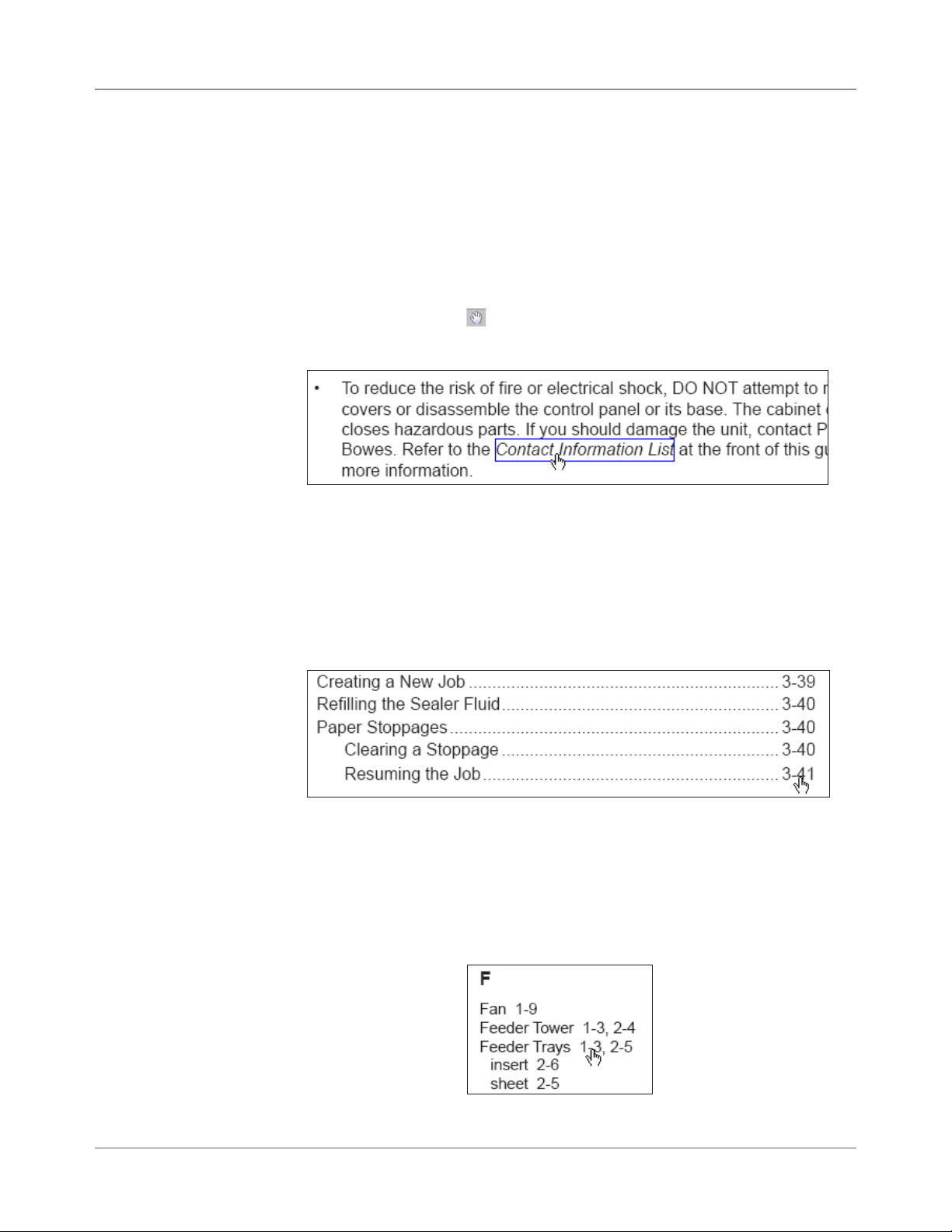
It is important to be familiar with this guide as it will enable you to utilize the
system to its full potential, while keeping problems to a minimum.
There are several built-in features you can use to navigate through this
guide when viewing it as a pdf file:
• Topics highlighted by a blue rectangle are hyperlinks.
Using the Hand tool ( ), you can click anywhere within a hyperlink to
jump to the topic's location in the Help guide.
Highlighted Hyperlink
• Entries in the main Table of Contents and the table of contents at the
beginning of every chapter are hyperlinks, although they are not highlighted.
Move the Hand tool over a table of contents entry until it points, then
click to jump to the location of the entry in the Help guide.
Table of Contents Hyperlink
• Page numbers in the Index are hyperlinks, although they are not highlighted.
Move the Hand tool over the page number until it points, then click on
the page number to jump to that page of the Help guide.
Index Hyperlink
1-2 SV61311 Rev. E
Page 13
Introduction • 1
About Your System
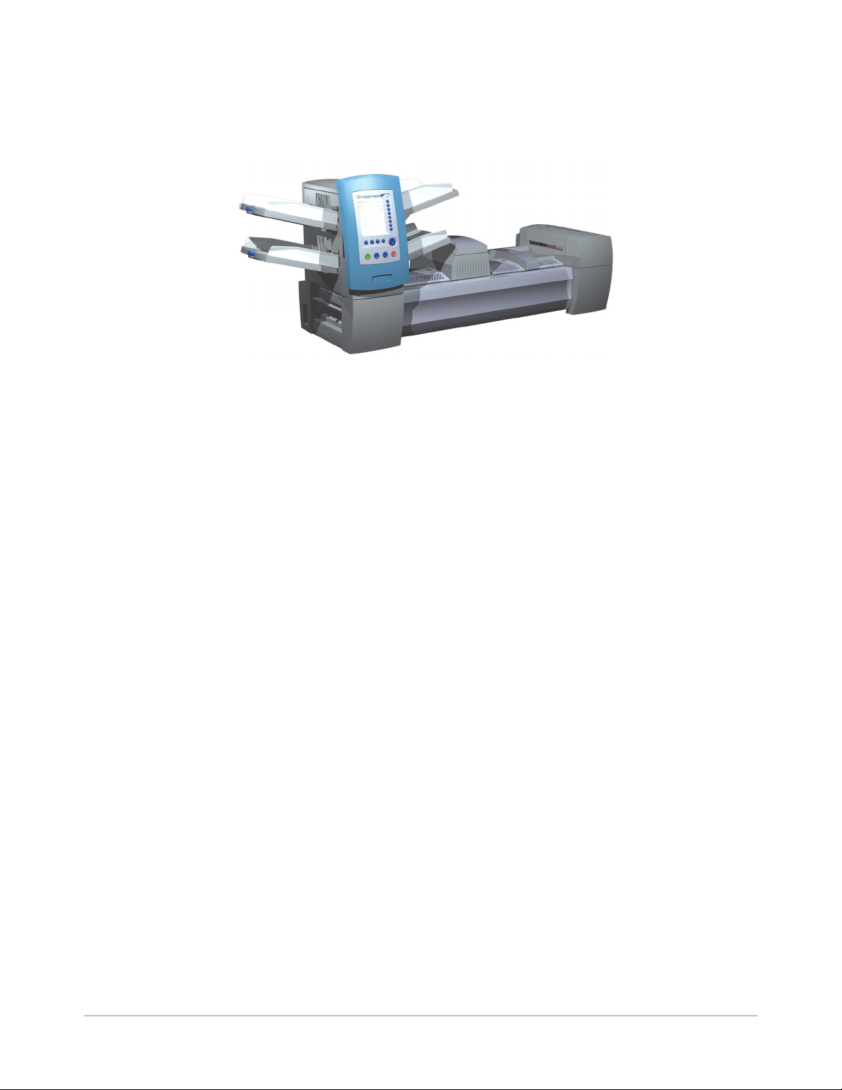
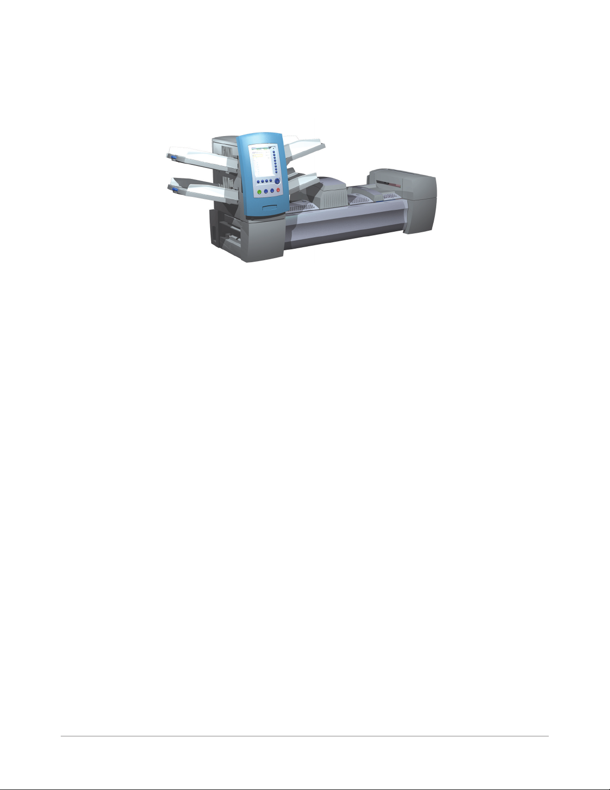
DI900/DI950 are high throughput, mail creation systems designed to handle
a broad range of applications with minimum operator setup adjustments.
These systems have the ability to feed, fold, and insert mail piece components into an outer envelope. The systems generate Letters or Flats as the
final mail piece. The systems also accept a variety of options that provide a
wide range of capacities and operating speeds.
Figure 1.1: The DI900 System
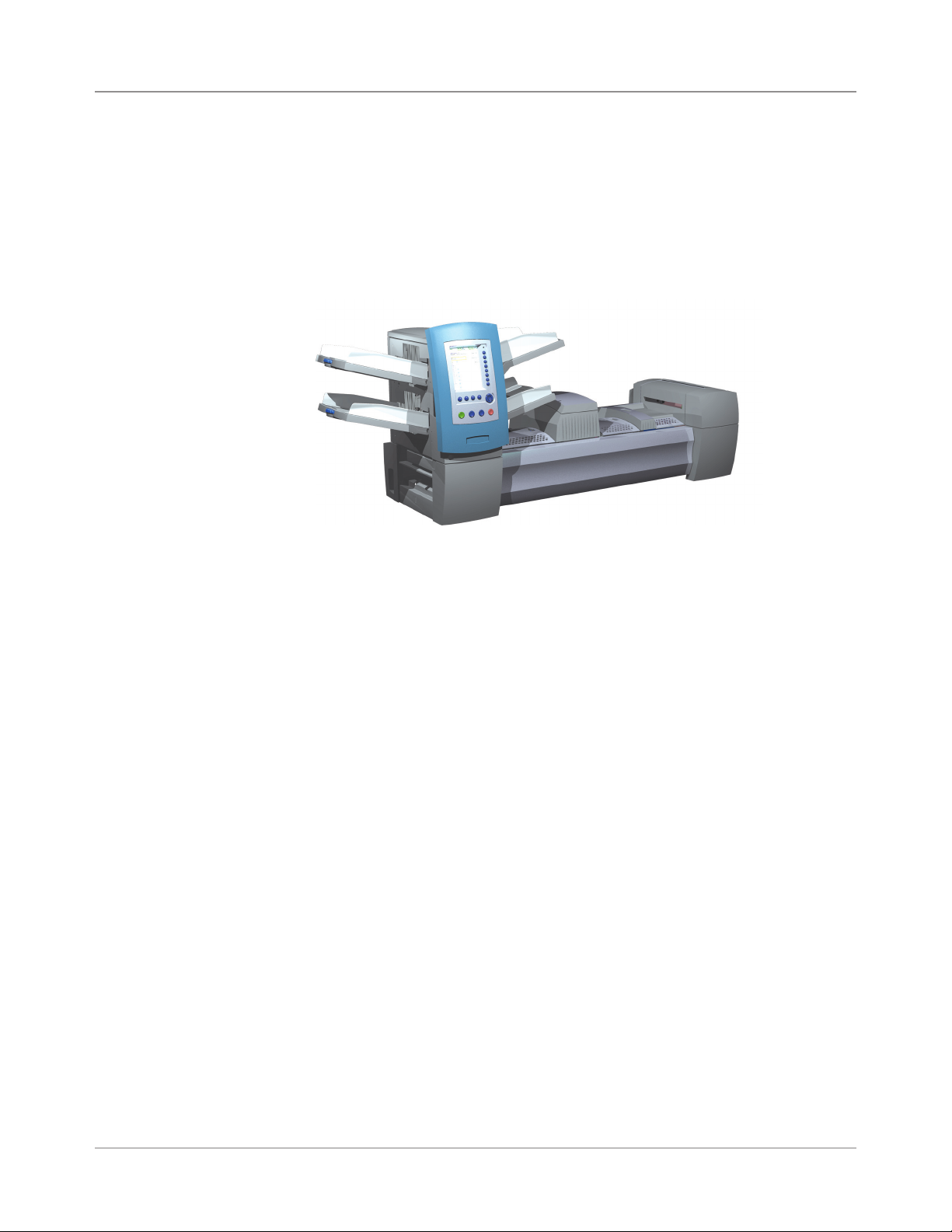
The systems can be configured with four flexible Feeder Trays. There are
two types of Feeder Trays:
• Sheet Trays, which are capable of feeding sheets; and
• Insert Trays, which are capable of feeding slip/insert materials, pre-folded inserts, thin booklets, and envelopes.
In addition, the DI950 system is equipped with a dedicated High Capacity
Envelope Feeder (HCEF) that allows for greater speed and throughput. The
systems also accept material from optional upstream input devices, such as
High Capacity Sheet Feeders, Attached Printer, and other devices.
Basic system features are summarized in this chapter. Refer to Chapter 6
for detailed equipment and material specifications.
The systems are configured with two major components:
• Feeder Tower, and
• Transport Deck.
The Feeder Tower sends material from the Feeder Trays to the Transport
Deck. Depending on the job parameters, the material may or may not need
to pass through the Folder in the Transport Deck. If it does, the system offers numerous types of folds and the ability to insert the folded material into
the appropriate position in the mail piece collation. The system can also seal
the envelope (Letter only) before sending the final mail piece to a stacking
unit.
SV61311 Rev. E
1-3
Page 14

1 • Introduction
Standard Systems
DI950C
DI950H
DI900C
DI900H
Letter and Flats Drop Stacker
(standard on all systems)
1-4 SV61311 Rev. E
Page 15
Introduction • 1
DI900/DI950 Document Printing Options - Beta
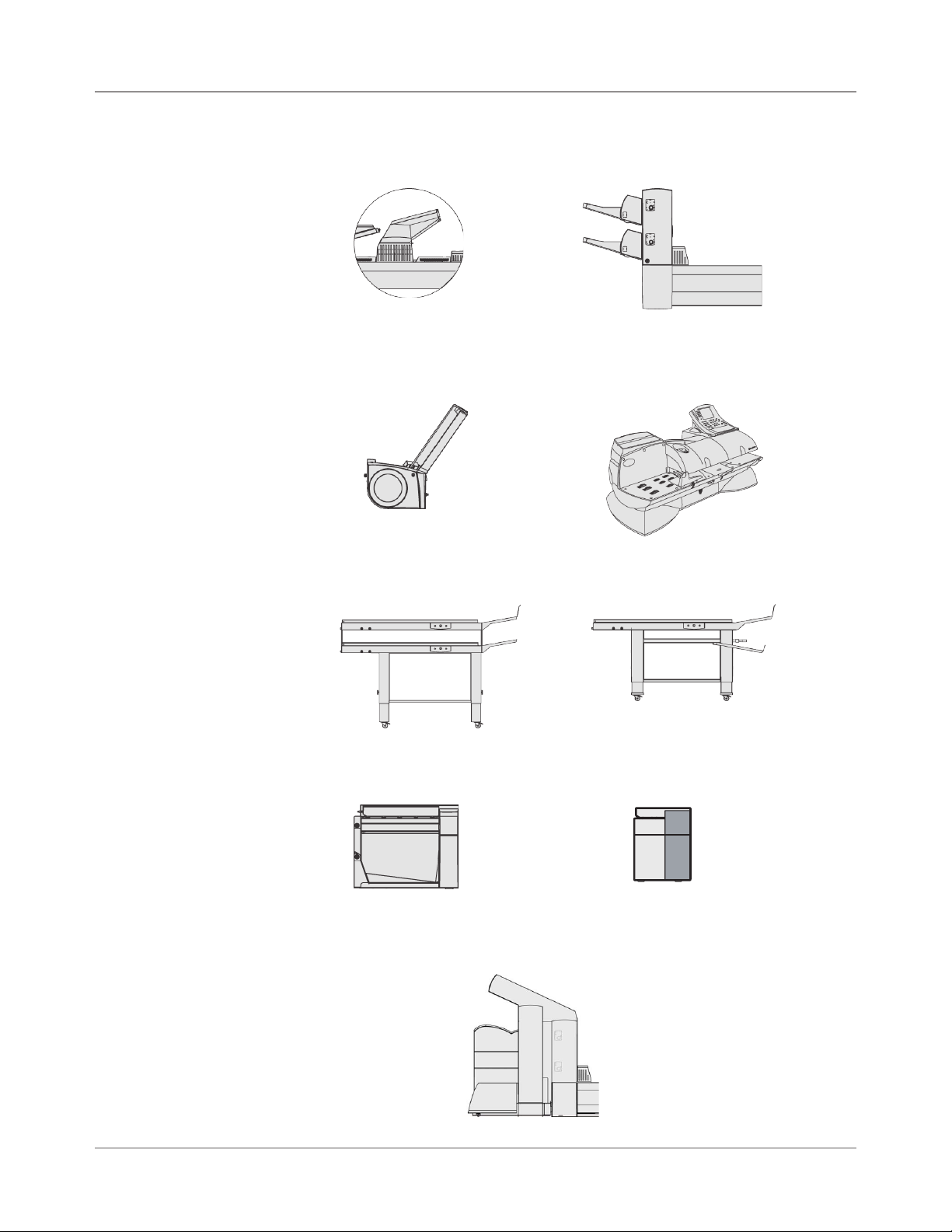
System Options*
*Furniture, designed
specifically for the
system, is also
available.
Fold Expansion Kit
(Document Inverter)
OptiFlow™ Vertical
Power Stacker
High Capacity Sheet
Feeder (HCSF)
DM Series™ Mailing System
DM800i™, DM1000
Belt StackerTandem Belt Stacker
™
SV61311 Rev. E
Exit Transport
Flats Sealer
Attached Printer
1-5
Page 16

1 • Introduction
Safety Information
Follow these precautions whenever you use your inserting system:
• Read all instructions before you attempt to operate the system. Keep the
Operator Guide accessible for quick reference.
• Use this equipment only for its intended purpose.
• Place the system close to an easily accessible wall outlet.
• Place the system in an accessible location to allow for proper venting of
the equipment and to facilitate servicing.
• Use the power cord supplied with the machine and plug it into a properly
grounded wall outlet that is located near the machine and easily accessible. Failure to properly ground the machine can result in severe personal
injury and/or fire.
• The power cord wall plug is the primary means of disconnecting the
machine from the AC supply.
• DO NOT use a wall outlet controlled by a wall switch or one that is
shared with other equipment.
• DO NOT use an adapter plug on the line cord or wall outlet.
• DO NOT remove the ground pin from the line cord.
• Make sure the area in front of the wall outlet into which the machine is
plugged is free from obstruction.
• DO NOT route the power cord over sharp edges or trap it between pieces of furniture. Make sure there is no strain on the power cord.
• To reduce the risk of fire or electrical shock, DO NOT attempt to remove
covers or disassemble the control panel or its base. The cabinet encloses hazardous parts. If you should damage the unit, contact Your system
supplier. Refer to the Contact Information List at the front of this guide
for more information.
• If the unit becomes damaged, unplug it from the wall, then contact Your
system supplier. Refer to the Contact Information List at the front of this
guide for more information.
• Keep fingers, long hair, jewelry and loose clothing away from moving
parts at all times.
• Avoid touching moving parts or materials while the machine is in use.
Before clearing a jam, be sure machine mechanisms come to a complete stop.
• Remove jammed material gently and carefully.
• Do not place lighted candles, cigarettes, cigars, etc., on the system.
• To prevent overheating, do not cover vent openings.
• Use only approved supplies, in particular aerosol duster. Improper storage and use of aerosol dusters or flammable aerosol dusters, can cause
an explosive-like condition that could result in a personal injury and/or
property damage. Never use aerosol dusters labeled flammable and
always read instructions and safety precautions on the duster container
label.
1-6 SV61311 Rev. E
Page 17
Introduction • 1
Safety
Information
(continued)
• To obtain supplies and/or Material Safety Data Sheets, contact your
system supplier. Refer to the Contact Information List at the front of this
guide for more information.
• Operation of this equipment without periodic maintenance will inhibit
optimum operating performance and could cause the equipment to malfunction. Contact your system supplier for the required service schedule.
• Always follow specific occupational safety and health standards for your
workplace.
• To reduce the risk of fire or electrical shock, DO NOT attempt to remove
covers or disassemble the control panel or its base. The cabinet encloses hazardous parts. If you should damage the unit, contact your system
supplier. Refer to the Contact Information List at the front of this guide for
more information.
If your stacker has an AC adapter to power the stacker:
• Use only the AC adapter designed specifically for the stacker. Third-party
AC adapters may damage the stacker.
• To protect against electrical shock, plug the AC adapter power cord into
a properly grounded wall outlet.
• Do not route the AC adapter cable over sharp edges or trap it between
furniture.
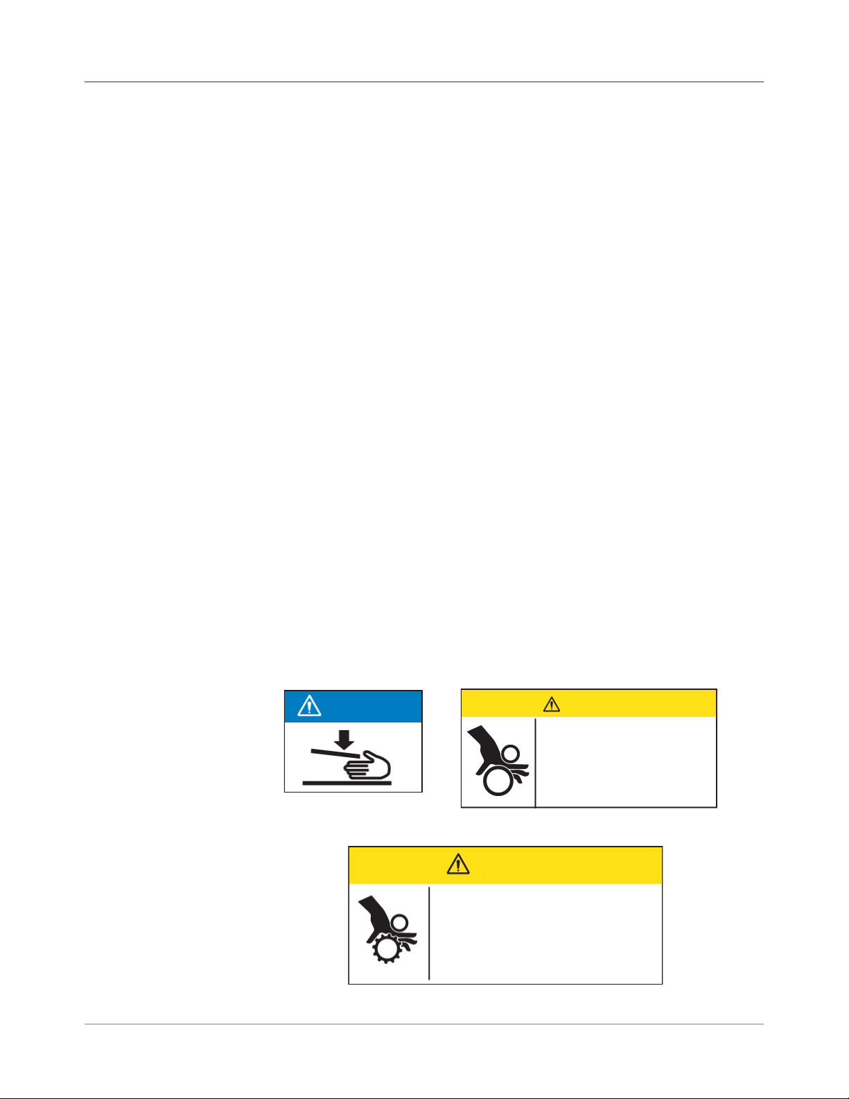
Warning Labels
The following warning labels are attached to modules on the system to alert
you to potential injury that could occur with careless operating procedures.
These same labels will be shown throughout the manual as they apply to
the various modules that are discussed in that section.
NOTICE
CAUTION
Moving mechanism can result
in personal injury.
Keep hands, long hair, ties,
jewelry and loose clothing
away from moving parts.
CAUTION
Moving mechanism can result in
personal injury.
Keep hands, long hair, ties,
jewelry and loose clothing away
from moving parts.
SV61311 Rev. E
1-7
Page 18

1 • Introduction
Book Contents
This remaining chapters in this book contain setup, operation, troubleshooting and reference information about your document inserting system.
• Chapter 2, Meet the Inserting System - orients you to system software
and hardware components.
• Chapter 3, Basic Operation - explains basic steps for running a job.
• Chapter 4, Advanced Operation - describes advanced procedures.
• Chapter 5, Troubleshooting - explains screen adjustment procedures,
lists errors and their corrective actions, and describes routine maintenance procedures.
• Chapter 6, Reference - lists system specifications.
• Chapter 7, Add-On Modules - provides a brief description of each add-
on module.
• Chapter 8, Scanning - explains scanning options.
• Appendix A, Glossary - contains definitions for commonly used terms,
and explanations of the icons you'll see on the display screen.
NOTE: Machine Keys will appear in all capital letters. Option Keys will appear in
Initial Caps in quotes ("). Variables within options will appear in quotes (") and in
the same case as shown on the screen.
1-8 SV61311 Rev. E
Page 19
2 • Meet the Inserting
System
System Components ...................................................................2-2
Feeder Tower ...............................................................................2-4
Feeder Trays ...............................................................................2-5
Sheet Trays ........................................................................... 2-5
Insert Trays ............................................................................ 2-6
Manual Feeder ............................................................................2-7
Transport Deck ............................................................................2-8
Mail Piece Path ...................................................................... 2-8
Pre-fold Accumulator ............................................................. 2-8
Folder .................................................................................... 2-9
Post-fold Accumulator ........................................................... 2-9
Insertion Area ........................................................................ 2-9
Folder Bypass Path ............................................................... 2-9
Moistener, Closer, Sealer ...................................................... 2-9
About the Control Panel ............................................................2-10
Screen Option Keys ............................................................. 2-10
Fixed Function Keys .............................................................2-11
Machine Action Keys ........................................................... 2-13
Screen Navigation Keys ...................................................... 2-13
Display Screen ..........................................................................2-14
Header Area ........................................................................ 2-14
Status Area .......................................................................... 2-15
Access Rights ............................................................................2-20
Logging In ............................................................................ 2-21
Logging Out ......................................................................... 2-21
About System Covers ................................................................2-22
Opening the Covers ............................................................. 2-23
Closing the Covers .............................................................. 2-23
About the Paper Release Knobs/Levers ...................................2-24
About Add-On Modules .............................................................2-24
SV61311 Rev. E
2-1
Page 20
2 • Meet the Inserting System
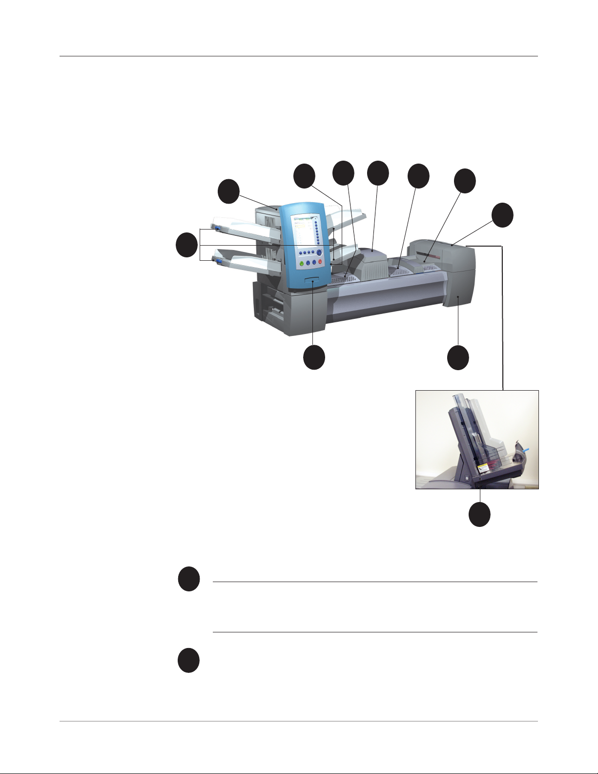
System Components
The base system configuration includes a Feeder Tower, Transport Deck,
and Envelope Sealer; the DI950 features an additional integrated High Capacity Envelope Feeder. Additional modules can be added to utilize the full
potential of the system.
3
4
5
6
7
2
8
1
10
9
Figure 2.1: The DI900 System
Feeder Tower Trays - feed sheets or inserts to the Feeder Tower.
1
NOTE: If enabled, the lower left Tray is assigned with the letter "A" on
the Mail Piece Icon Tree. When a High Capacity Envelope Feeder is not
part of the system conguration, this Tray is the primary Tray for feeding
envelopes designated for a given job.
Feeder Tower - is a two-sided Tray holder/material feeder.
2
11
DI950 only
2-2 SV61311 Rev. E
Page 21

Meet the Inserting System • 2
System
Components
(continued)
Manual Feeder - allows you to manually feed stapled or unstapled
3
sets of up to 5 sheets of 20 lb (80gsm) paper. The machine waits for
each set to be manually fed before folding and inserting the set automatically into the envelope. The Manual Feed option is available
during job creation. Inserts and/or Sheets from other Trays can also
be added to the job.
Pre-fold Accumulator - is a staging area for the material that
4
needs to be collated together and then sent to the Folder unit.
Folder - applies one of the available fold types to Sheets.
5
Post-fold Accumulator - is a staging area for the folded Sheets to
6
meet any inserts that are to be included.
Insertion Area - is the part of the transport where the collation in-
7
tended for a single addressee is inserted into an outer envelope.
Moistener, Closer, Sealer - Brushes sweep across the envelope
8
flap to wet the glued area of the flap. The letter-size envelope then
moves through the Closer and Sealer areas of the unit to complete
the mail piece.
Sealing Solution Bottle - is located inside an opening cover at the
9
front right side of the machine. It provides sealing solution to the
envelope sealing system.
10
11
Drop Stacker (available on all units, not illustrated) or Power Stacker
(Optional, not illustrated) - collects and neatly stacks the finished mail
pieces that exit the system. The drop stacker can be unlatched from the
system when it is not needed. The power stacker is mounted to the system.
Control Panel - allows you to run the machine and configure job
settings. It also displays the machine status and shows loading instructions and details of the job. See the following pages for more
information on the controls and screen.
High Capacity Envelope Feeder (DI950 only) - holds at least 500
letter-sized envelopes. It feeds directly to the Insertion Area.
SV61311 Rev. E
2-3
Page 22
2 • Meet the Inserting System
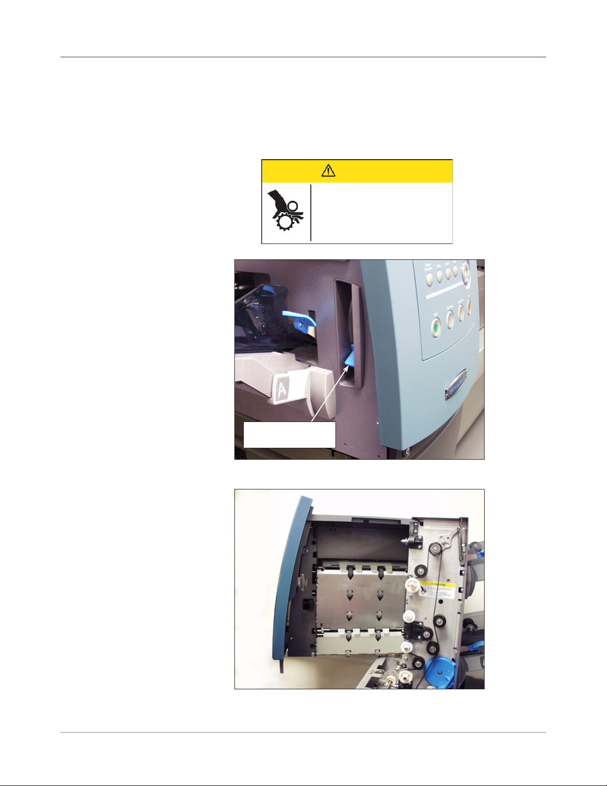
Feeder Tower
The Feeder Tower is a two-sided Tray holder/material feeder that stands at
one end of the unit. Unlocking a latch on the left side of the Tower opens it to
expose Feeder Exit and Tower Transport Rollers. This makes it easy to access media that may stop as it exits the Tower. Depending on the Configuration, the Tower accepts two or four Feeder Trays.
CAUTION
Moving mechanism can result in
personal injury.
Keep hands, long hair, ties,
jewelry and loose clothing away
from moving parts.
Push latch up to
open Tower cover
Figure 2.2.1: Latch Opens Feeder Tower.
Figure 2.2.2: Two-sided Feeder Tower: Open for easy
access to Feed Rollers.
2-4 SV61311 Rev. E
Page 23

Meet the Inserting System • 2
Feeder Trays
Sheet Trays
There are two types of Feeder Trays:
• Sheet Trays
• Insert Trays
The required Tray type is based on the type of material selected for a given
job.
Sheet Trays feed flat, unfolded material. Use only the recommended materials. Refer to the specifications in Chapter 6.
NOTE: Sheet Trays have ll marks on their side walls. Be sure to keep your stack
of materials at or below these marks to avoid feed problems.
SV61311 Rev. E
Figure 2.3.1: Sheet Trays
2-5
Page 24
2 • Meet the Inserting System
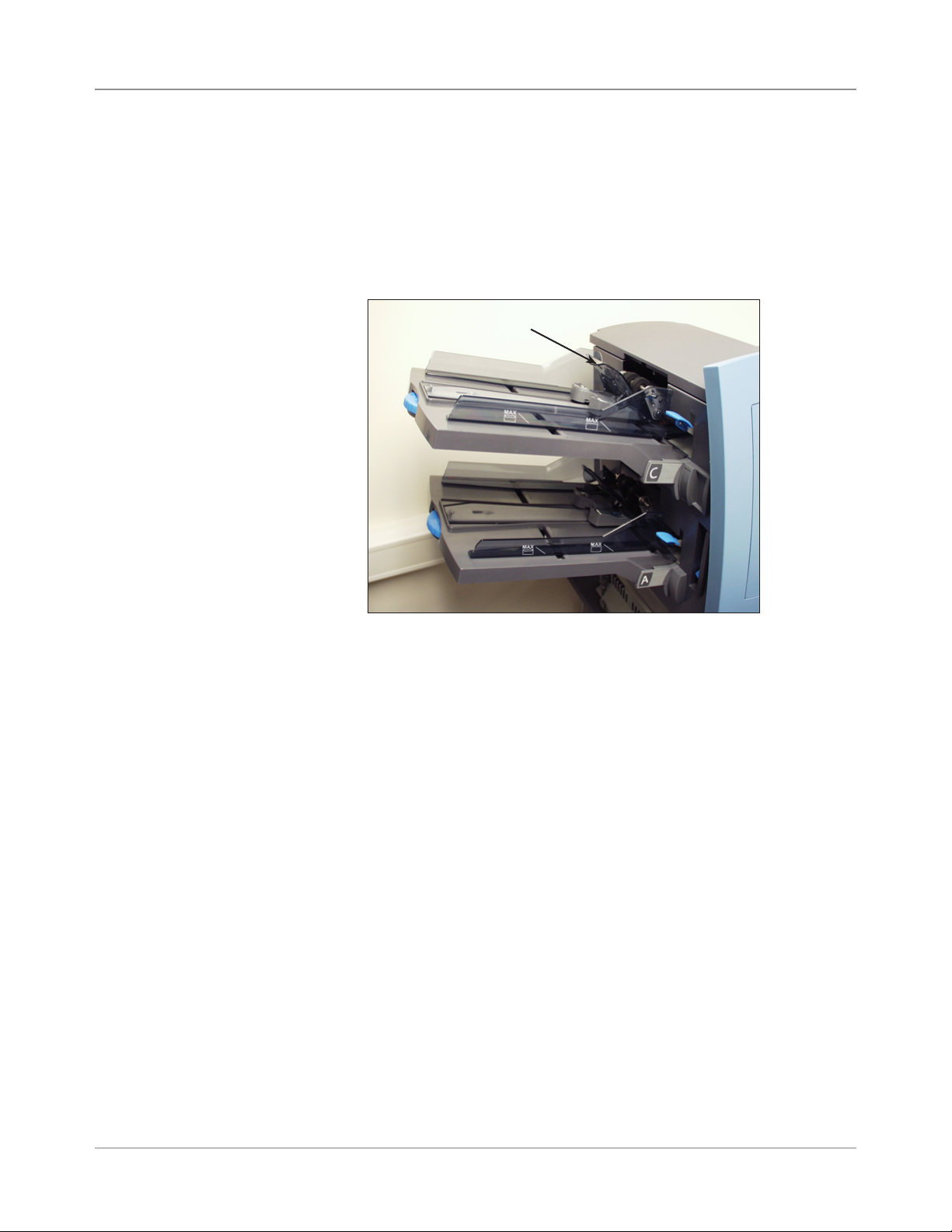
Insert Trays
Insert Trays feed items that do not need folding (envelopes, cards, booklets,
slips and pre-folded media) into the system. Insert Trays have a weighted
sliding mechanism known as a Sled that keeps pressure on the material for
proper feeding.
Insert Trays have two sets of maximum fill lines: one set for slips, and a
second set for envelopes.
Sled mechanism
Figure 2.3.2: Insert Tray
2-6 SV61311 Rev. E
Page 25
Meet the Inserting System • 2
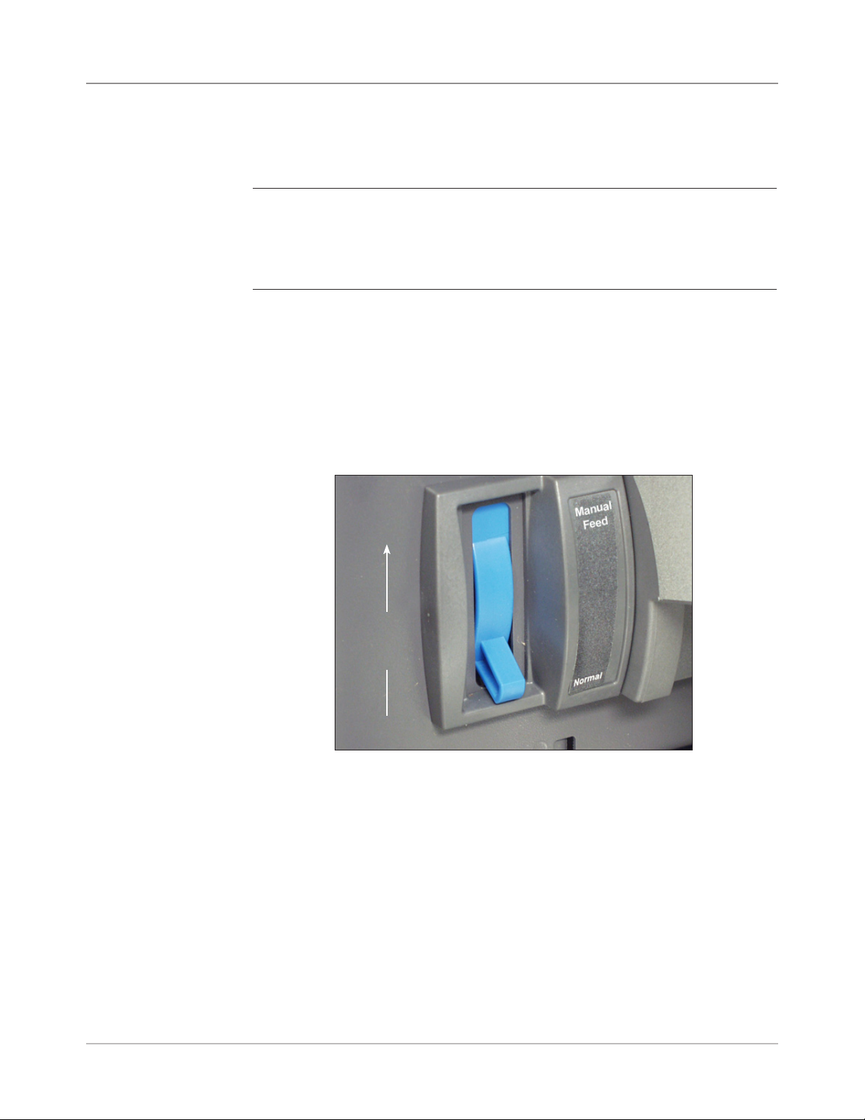
Manual Feeder
Use the Manual Feeder to hand feed stapled or unstapled sets of up to five
sheets. The machine waits for each set to be manually fed before folding
and inserting the set into the envelope.
NOTES:
• The feeder type of the item (to be fed manually) in the current job has to be
dened as Manual for the feature to work.
• The job with the manual fed piece can also include items from other feeders,
including sheets or inserts.
To use the Manual Feeder:
1. Select a job that uses the Manual Feeder.
2. Push the Manual Feed lever up.
3. Press TRIAL PIECE to start the machine.
4. Feed each set by pushing the edge into the rollers one at a time.
5. Push the lever down when you are done.
Push the
Manual Feed
lever up.
Figure 2.4: Manual Feed Lever.
SV61311 Rev. E
2-7
Page 26
2 • Meet the Inserting System
Transport Deck
The Transport Deck accepts material from the Feeder Tower and moves it
through the various modules to produce a finished mail piece. The Standard
Transport Deck consists of the following:
Pre-fold Accumulator
Figure 2.5: Transport Deck
Folder
Post-fold
Accumulator
Insertion
Area
Moistener,
Closer,
Sealer
Mail Piece Path
Pre-fold
Accumulator
2-8 SV61311 Rev. E
Material from the Feeder Trays comes down the Feeder Tower in a pre-defined order. Material moves rapidly from one station to the next in the Transport Deck to produce a finished mail piece that is dropped into a stacking
bin or onto an optional high capacity output stacker. A brief description of the
function of each module in the paper path is presented next.
The Pre-fold Accumulator is the first stop in the paper path. The Pre-fold
Accumulator is a stacking place for the material that needs to be collated
and folded. When the appropriate components for one mail piece finish collating on the Pre-fold Accumulator, they move into the Folder.
Page 27

Meet the Inserting System • 2
Folder
Post-fold Accumulator
Insertion Area
The stack of collated sheets exits the Pre-fold Accumulator into the Folder.
The Folder then applies a fold to the stack and sends it to the Post-fold Ac-
cumulator. The Folder offers these options:
• C Fold,
• Z Fold,
• Single Fold,
• Double Fold, and
• No Fold.
An optional Inverter may be used for some address location/fold type combi-
nations.
The accumulation of folded sheets exits the Folder onto the Post-fold
Accumulator area. Other components of the mail piece, such as a Business
Reply Envelope or a pre-folded insert, are added to the accumulation in the
Post-fold Accumulator area. When all components are present, the stack
moves to the Insertion Area.
The contents of the mail piece meet the outer envelope at the Insertion
Area. The envelope arrives at the Insertion Area with its front face down and
flap open. Envelope Openers on the Insertion Area open the envelope wide
enough to allow the contents to be slid inside.
Folder Bypass Path
Moistener, Closer, Sealer
SV61311 Rev. E
The outer envelope, fed from the Feeder, that will contain the collated media
runs through the bottom part of the Transport Deck. The route this envelope
travels is known as the Folder Bypass Path.
As the envelope passes over the Moistener, brushes sweep across the top
of the flap to wet the glued area of the flap. The envelope is then inverted
and slid through the Closer and Sealer portion of the system to complete the
mail piece. From there, the mail piece is dropped onto a stacker.
2-9
Page 28
2 • Meet the Inserting System
About the Control Panel
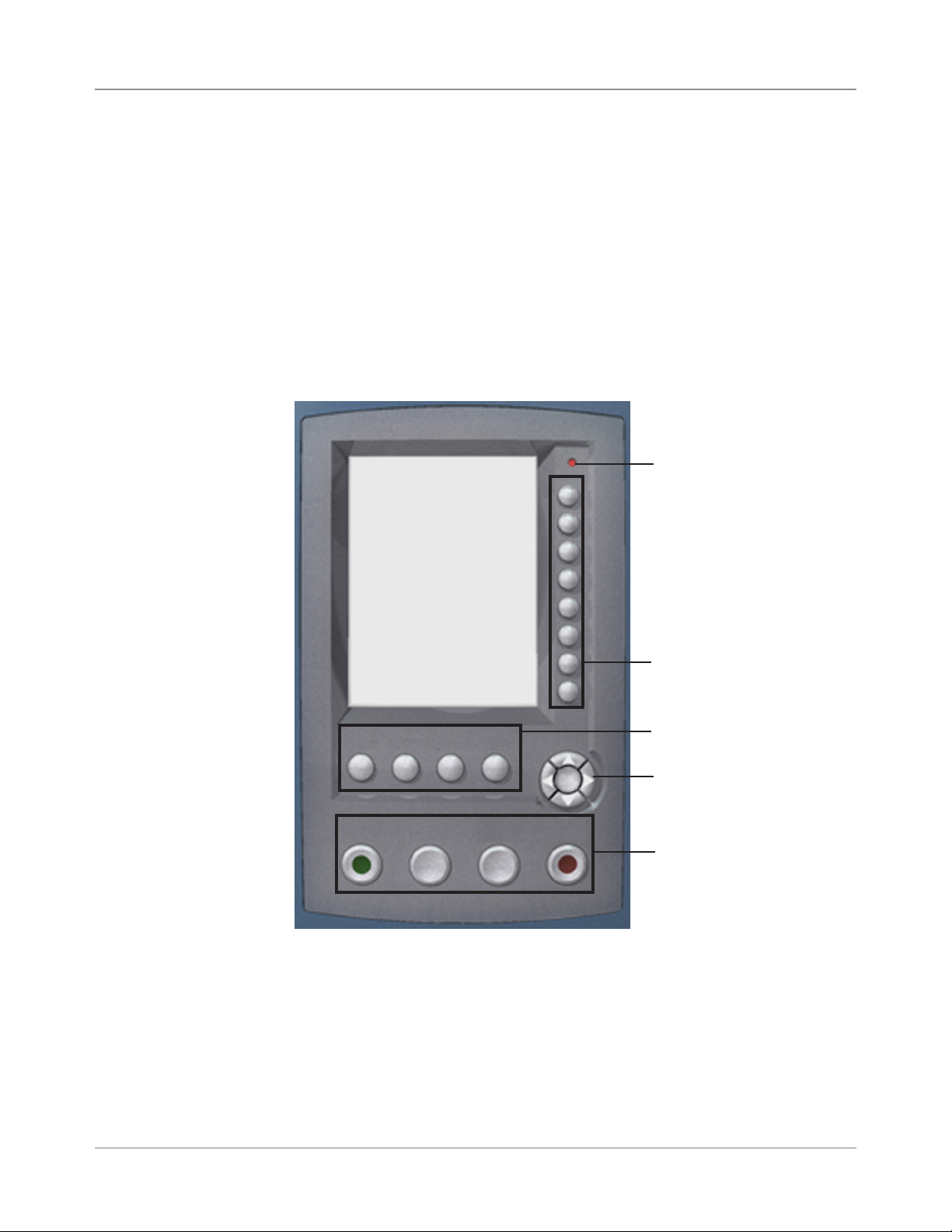
The Control Panel consists of the following components:
• Screen Option Keys allow you to define settings for up to 24 jobs that
you can store in the system’s memory. These keys also provide the
means to edit any of the stored jobs.
• Fixed Function Keys allow you to access the system’s built-in tools that
appear on the screen (such as the system’s help file).
• Screen Navigation Keys allow you to move UP/DOWN and right/left in
the Display and to apply selections that you’ve made.
• Machine Action Keys control hardware components and mechanical
movements.
• LED Status Indicator
LED Status Indicator
Screen Option Keys
Screen Option Keys
Reset
Counter
Start
Help
Trial
Piece
Cancel
Home
Clear
Deck
OK
Stop
Fixed Function Keys
Screen Navigation Keys
Machine Action Keys
Control Panel
The Screen Option Keys are the eight keys on the right side of the screen.
These keys correspond to options on the screen, and therefore have no
dedicated labels. Use these keys to highlight an item in a displayed pick list
and/or to select the associated menu, item, action, or option.
2-10 SV61311 Rev. E
Page 29
Meet the Inserting System • 2
Fixed Function Keys
The Fixed Function Keys are the top row of keys under the screen. Each
of these keys has an assigned function that is enabled or disabled based
on the screen that displays. Use of each of these keys is explained next in
more detail.
Reset Counters
The system has two
counters:
• Piece Counter
• Batch Counter
Reset Counters
Job Items
Piece Count
A
Batch Count
B
D
Job: ABC
Both
SV61311 Rev. E
Reset Counters Screen
Resetting the Piece Counter
The Piece Counter appears in the bottom portion of the Display screen. It is
a cumulative counter, i.e., it increments for each completed mail piece.
If you run the same job but for a different customer and/or use different
materials, you'll need to zero the counter and ready it for counting the completed mail pieces in the new run.
To reset the Piece Counter:
1. Press RESET COUNTERS to display the Reset Counters screen.
2. Select "Piece Count".
3. You will be returned to the Home screen. The Piece Counter at the bottom of the screen will read "0".
2-11
Page 30

2 • Meet the Inserting System
Fixed Function
Keys (continued)
Resetting the Batch Counter
The Batch Counter counts up to a set number. It increments one count for
each completed mail piece that the system detects. The system stops when
it reaches the batch count.
To reset the desired number for the job you are running:
1. Press RESET COUNTERS to display the Reset Counters screen.
2. Select "Batch Count".
3. You will be returned to the Home screen. The Batch Counter at the bottom of the screen will return to its original setting.
NOTE: The original setting for the Batch Counter cannot be less than “5” or
greater than “9999”.
Resetting Both Counters
The Reset Both selection allows you to reset both the Piece Counter and the
Batch Counter to zero.
1. Press RESET COUNTERS to display the Reset Counters screen.
2. Select "Both".
3. You will be returned to the Home screen. The Piece Counter at the bottom of the screen will read "0" and the Batch Counter will return to its
original setting.
Help
Select "Help" for information about the screen that currently displays and for
access to the entire Help file.
Cancel
Select "Cancel" to return to the previous screen.
NOTE: If you made changes to a job before pressing "Cancel", you are prompted
to save the changes. Press "Yes" to save the changes; press "No" to delete the
changes and to return to the last screen in which you saved changes. Be aware
that once you delete the changes, they are permanently gone.
Home
Select "HOME" to return to the Home screen for the current job. The current
job will automatically include any changes made while editing the job. Although the job can be run now, the changes are not saved until you choose
"Save Job" from the menu. Jobs that have been changed but not saved
have an asterisk next to the job name at the top of the Home screen.
2-12 SV61311 Rev. E
Page 31

Meet the Inserting System • 2
Machine Action Keys
The four keys along the bottom of the Control Panel are called Machine Action keys. Use these keys to run the system.
Start
Machine Action Keys
Trial
Piece
Clear
Deck
Stop
Start
Press this green-colored key to begin running the selected job.
Trial Piece
Press TRIAL PIECE to do a test run on your job. One complete mail piece
will be prepared. This allows you to verify that your job settings are correct,
that the mail piece looks the way you want it to look, and that the system is
functioning properly.
NOTES:
• Even if the job calls for a sealed mail piece, the trial piece will be unsealed for
easy inspection.
• Double Detect is set when the trial piece is created. Examine the contents of
the mail piece to ensure the correct number of items have been inserted into
the envelope.
Screen Navigation Keys
Clear Deck
Press CLEAR DECK to rid the system of materials currently in process in
the paper paths.
NOTE: Only press CLEAR DECK when prompted by the system to minimize lost
material and manual mail piece generation.
Stop
Press STOP to finish in-process mail.
The Screen Navigation Keys move the cursor on the
screen. They are used to highlight items in the Mail Piece
Icon Tree.
The Screen Navigation Keys consist of a two-tiered circular button. The outer tier houses UP/DOWN and LEFT/
RIGHT Arrow Keys that move the cursor UP/DOWN and
LEFT/RIGHT on the screen. The inner tier of the Screen
Navigation Keys is an OK button.
Press OK whenever you want to apply the selection that you made using
the Arrow Keys.
OK
Screen
Navigation Keys
SV61311 Rev. E
2-13
Page 32

2 • Meet the Inserting System
Display Screen
The Display screen is divided into two major areas:
• Header area
• Status area
Header Area
Home
Run Trial Piece
Job Items
Select Another Job
A
B
Status Area
Loading Instructions and
D
Pre-Run Adjustments
Job: ABC
Low Sealant
SwiftStart
Menu
Header Area
Pieces :1658
Display screen
The Header area has two colored bands that run across the top of the
screen: the top band is blue, the bottom band is green. The left side of the
top band displays the name of the screen in which you are working. Depending on the screen you select, the Job Name may show on the right side
of this area. The green band displays instructions and screen navigation
directions.
The top (blue) band displays the name of the
screen and Job.
Home
Run Trial Piece
The bottom (green) band displays the instructions and
screen navigational directions.
If the job uses the Attached Printer,
the mail run name displays in the
middle of the top (blue) band.
Job: ABC
Low Sealant
2-14 SV61311 Rev. E
Page 33

Meet the Inserting System • 2
Status Area
The Status area of the screen is devoted to displaying information about the
task(s) you are performing. This area displays any or all of the following:
• Mail Piece Icon Tree
• Item Orientation
• Options
• Data displaying across the bottom of the screen in the Home screen
only includes batch count, piece count and User ID.
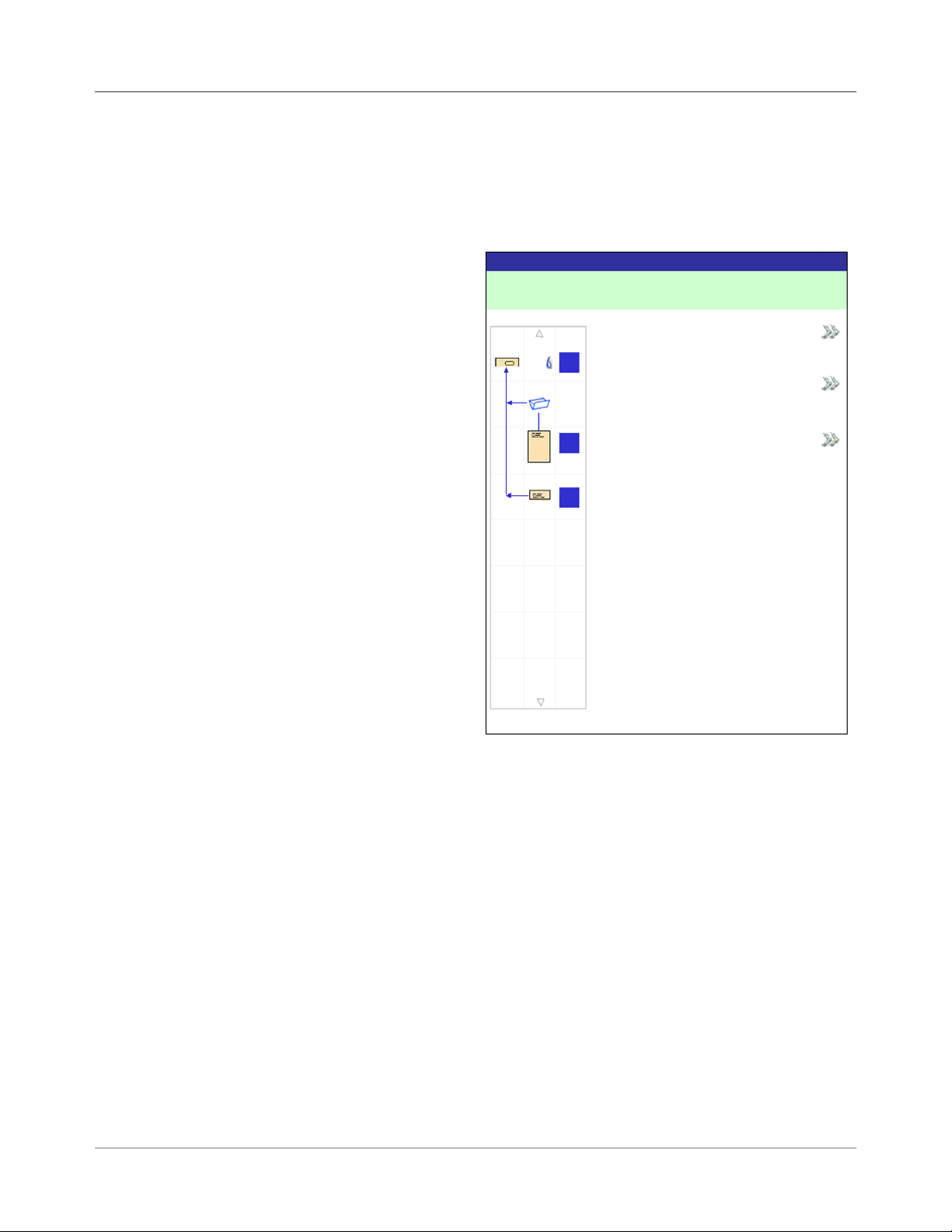
Mail Piece Icon Tree
The Mail Piece Icon Tree is located on the left side of the screen. The Tree
displays an icon for each component in the mail piece and a fold icon, if the
material is to be folded. The icons are arranged in the order in which the
mail piece components will be collated, with the outer envelope icon
showing at the top of the Tree. A letter appearing alongside the icon des-
ignates the Feeder Tray assignment; a small blue droplet icon indicates that
the seal feature is enabled.
• Each icon has one darker edge either at the top or bottom that indicates
the leading edge of the material. The leading edge of an object is the
edge that feeds into the machine first. For example, a sheet that must
be loaded face up with the top of the sheet leading would be represented by a "face-up" sheet icon containing a "leading edge" line on top.
Leading Edge
Sheet, Face Up
• A Feeder assignment letter will be placed alongside the icon to indicate
the Feeder Tray to load the object into. Two or more feeder assignment
letters alongside a single icon indicate that Feeder Trays have been
linked. The item should be loaded in all the Feeder Trays indicated.
When one Feeder Tray becomes empty, feed will automatically switch to
the next linked Feeder Tray, in a continuous cycle.
• If Double Detect is in use, the Double Detect icon will appear immediately to the left of the relevant icon.
Double Detect
Icon
A
Linked Feeders
C
SV61311 Rev. E
Feeder Assignment Letter
2-15
Page 34

2 • Meet the Inserting System
Status Area
(continued)
• If any Sheet Feeder(s) are programmed to feed multiple sheets, a modified icon indicating multiple sheets will appear together with a number
showing the number of sheets in the set.
3
Number of sheets in set
• On a scanning (OMR or Barcode) job, a variable number of sheets might
be fed under control of the OMR or Barcode marks and so a small letter
"n" will appear in place of the number.
n
Indicates variable number of sheets in set (scanning jobs only)
• Lines between the icons indicate the way the mailpiece is assembled.
The outer envelope is at the top of the icon tree.
• Making any change to the job settings can cause the Feeder Tray assignments to change in the Mail Piece Icon Tree.
NOTE: Any time the job set up changes, be sure to check the Mail Piece Icon
Tree for changes in the Feeder Tray assignments.
2-16 SV61311 Rev. E
Page 35

Meet the Inserting System • 2
Status Area
(continued)
Mail Piece Icon Tree Example
Each icon displays important information about the mail piece component
that it represents. The following explains information conveyed by the icon
and how it assists you in loading and running a job.
Window Envelope loaded flap down, flap
G
last. Envelope sealing turned on, loaded
into Feeder G.
C Fold selected.
Top address loaded Face Up, fed Top First,
loaded into Feeder C. Double Detect is on.
C
Additional Sheet - (No address) loaded Face
B
Up, fed Top First loaded into Feeders B
and D; Feeders B and D are linked. (Linked
D
Trays will always be on the same side of the
Tower.) Double Detect is on.
Reply Envelope loaded Flap Side Down, fed
A
Flap First, loaded into Feeder A.
Example: Mail Piece Icon Tree
NOTES:
• In the example above, the Top Address, Additional Sheet and C Fold icons
represent a set. That is, the Top Address and Additional Sheets are accumulated together, and the C Fold is applied to them.
• An Insert (see the Reply Envelope icon, above) always appears as a single
set within the Mail Piece Icon Tree.
SV61311 Rev. E
2-17
Page 36
2 • Meet the Inserting System
Status Area
(continued)
Item Orientation
Use the Screen Navigation Keys to highlight an icon in the Mail Piece Icon
Tree to display information about the item that the icon represents. In most
instances, a picture appears in the Status Area of the screen and shows the
required orientation for loading the item into the Tray.
Figure 2.6: Sample - Material Orientation Picture
2-18 SV61311 Rev. E
Page 37

Meet the Inserting System • 2
Status Area
(continued)
Jobs
Job Items
A
D
B
Options
The right side of the Display screen lists the options that are available for
the screen that currently displays. In some screens, options consist of other
functions: in other screens options consist of different settings for a selected
item in the screen. Selection of the available options is done via the Screen
Option Keys, that were described earlier in this chapter. See the example
screens below.
Job: 123
Select Job
A
Edit Current Job
D
C
B
C
Review Current Job
Save Current Job
Create New Job
Edit Outer Envelope
Job Items
A
A
D
B
D
C
B
C
Name: ENV1
Size: Letter
Window: Yes
Type: Standard Flap
Seal: On
Job: 123
Delete Saved Job
Example: Functions Display
NOTE: Two Chevrons ( >>) indicate that there is a submenu of options. One
Chevron (>) indicates that there is a toggle between two choices, such as Yes/No
or On/Off.
Footer
Data across the bottom of the Home screen identifies the user and account.
Finished
Depth: Auto Measure
Additional Settings
Accept
Example: Options Display
SV61311 Rev. E
2-19
Page 38

2 • Meet the Inserting System
Access Rights
There are two security modes available on the system:
• Login Not Required Mode - requires four-digit access code to perform
supervisor and manager functions.
• Login Required Mode - sets up access levels and requires a user ID and
password for all system operator, supervisor, and manager functions.
The system has three levels of user access, and one level for service per-
sonnel. The three user access levels are:
• Operator
• Supervisor
• Manager
Depending upon the security mode, the supervisor and manager access
levels requires entry of an access code or user ID and password. These are
assigned by the system manager.
Operators have access to any of the function not listed as supervisor or
manager functions. System operators may be required to log in and out of
the system, if a security mode has been enabled.
Chapter 3 describes the steps involved with performing each of the non-restricted procedures.
Supervisors have access to all Operator functions and the following after
logging in with the correct access code or user ID and password:
• Saving a Job
• Deleting a Job
• Creating Accounts
• Deleting Accounts
Chapter 4 describes the steps involved with performing these supervisorlevel functions.
Managers have access rights to all of the above functions plus exclusive
rights to manage other users, i.e., assign/restrict functions and selecting the
Account Mode.
Chapter 4 explains the process for assigning user IDs and passwords and
selecting the Account Mode.
2-20 SV61311 Rev. E
Page 39

Meet the Inserting System • 2
Access Rights
(continued)
Logging In
When the Login Required Mode is enabled, entry of a user ID and password
is needed to access the system. When Login Not Required Mode is enabled,
entry of an access code is needed to access restricted functions.
NOTE: The Manager assigns the user ID and password or access code. User
IDs can contain alphanumeric characters; access codes and passwords must be
numeric only.
If one of the two security modes is enabled on your system, you must log in
to perform operator functions:
1. The Select User screen displays. Select the appropriate user ID.
NOTE: If necessary, press "Next" to view additional user IDs.
2. Enter your password.
NOTE: Passwords are four-digit numeric codes. Numbers 1, 2, 3, 4 and 5
display on the rst screen. Press "Next" to access numbers 6, 7, 8, 9, and 0.
3. Press "Accept" once you have entered your password. The Home
screen displays.
If Login Not Required Mode is enabled on your system and user IDs and
passwords have been set up by the Manager, the Log In option displays on
the Home screen.
Logging Out
To log out of the system: on the Home screen, select "Log Out".
NOTE: You must log out of the system in order for the next operator to log in.
SV61311 Rev. E
2-21
Page 40

2 • Meet the Inserting System
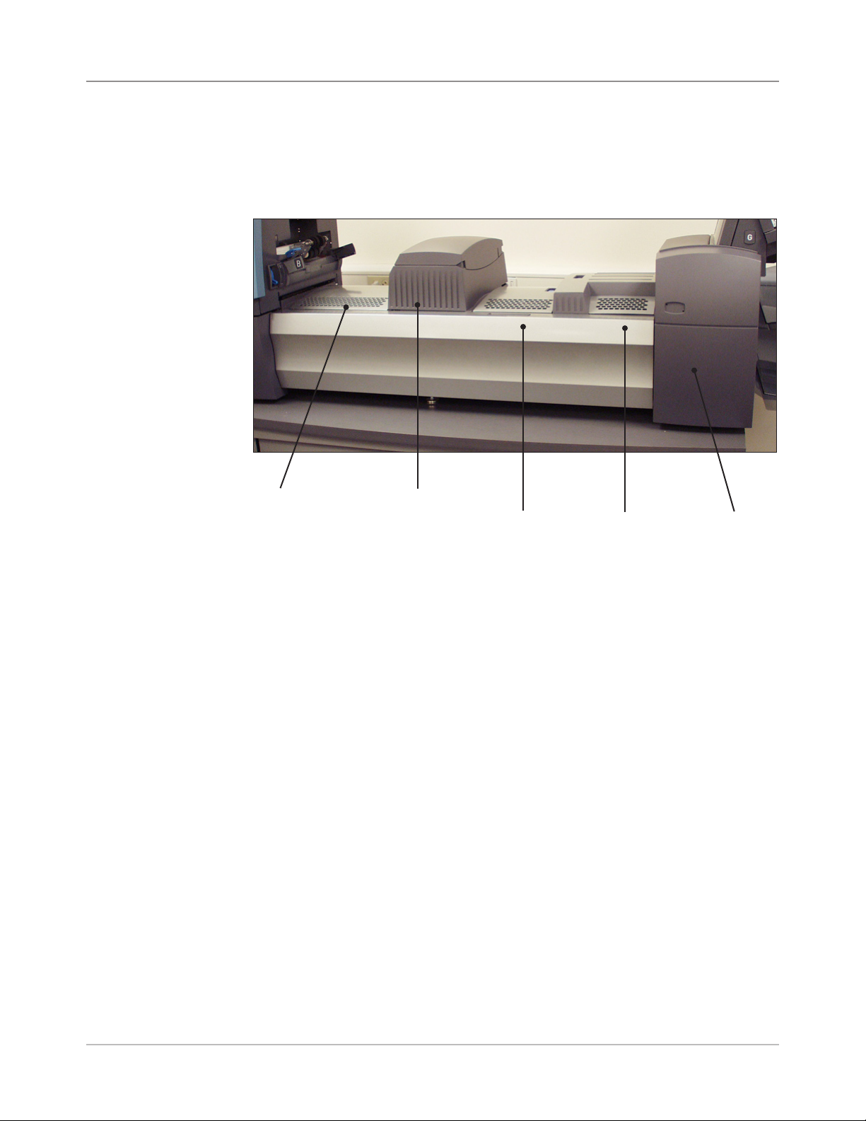
About System Covers
Three covers on the front side of the system, as shown in the figure below,
open to provide access to Paper Release Knobs.
Tower Base Cover
(closed)
Figure 2.7.1: Front Covers
Main Transport
Deck Cover
(open)
Sealer Replacement
Cover
(closed)
Covers on the top of the Transport Deck open to provide access to the roll-
ers in the main paper path:
Pre-fold
Accumulator
Cover
Figure 2.7.2: Top Covers
Folder
Cover
Post-fold
Accumulator
Cover
Insertion
Area
Cover
2-22 SV61311 Rev. E
Page 41

Meet the Inserting System • 2
Opening the Covers
The Tower Base Cover interlocks with the Main Transport Deck Cover. This
means that you cannot open the Tower Base Cover unless you open the
Main Transport Deck Cover first.
CAUTION
Moving mechanism can result in
personal injury.
Keep hands, long hair, ties,
jewelry and loose clothing away
from moving parts.
To open the Main Transport Deck Cover:
1. Place your fingers into the slot on the top of the cover.
2. Pull down gently. A security tie keeps the cover within the recommended
range of movement.
IMPORTANT: Do NOT lean on the open cover.
To open the Tower Base Cover:
1. Open the Main Transport Deck Cover.
2. Pull down on the Tower Base Cover handle.
Closing the Covers
SV61311 Rev. E
To close the Lower Tower and/or the Main Transport Cover, push the cover
up until it is seated in place on the system deck.
2-23
Page 42

2 • Meet the Inserting System
1
7
8
2
4
9
6
1
4
2
7
8
9
6
About the Paper Release Knobs/ Levers
There are ten Paper Release Knobs and Levers on the front side of the system. Each knob provides the means to turn rollers, and thus move material
out of the area in which it stalled. Each Paper Release Lever opens an area
of the system and allows you to clear any material that may have stalled.
The illustrations below indicate the various knob/lever locations, as well as
the areas each knob moves material through and each lever opens.
Controlled by Knob Z
Paper Release Knob/Lever Locations and Related Areas
About Add-On Modules
2-24 SV61311 Rev. E
The system accepts a number of additional modules. Refer to the Chapter 7
for more information.
Page 43

3 • Basic Operation
Connecting to Power ...................................................................3-2
Powering Up ................................................................................3-2
Home Screen...............................................................................3-3
Job Overview ...............................................................................3-4
Selecting the Job .........................................................................3-5
Setting Up Feeders and Loading Materials .................................3-6
Attaching Trays to the Feeder Tower ..................................... 3-6
Removing Trays from the Feeder Tower ............................... 3-7
Loading Material into the Trays ............................................. 3-8
Loading the DI950 High Capacity Envelope Feeder
(HCEF) ............................................................................... 3-13
Making Pre-Run Adjustments ...................................................3-18
Adjusting the Envelope Openers ......................................... 3-18
Running a Trial Piece ................................................................3-22
Reviewing the Job Settings ................................................. 3-24
Starting the Job .........................................................................3-25
SwiftStart™ Jobs .........................................................................3-25
Using SwiftStart™ ................................................................ 3-26
Creating a Job ...........................................................................3-26
Job Options ...............................................................................3-30
Envelope Options ................................................................ 3-30
Fold Options ........................................................................ 3-32
Sheet Options ...................................................................... 3-33
Insert Options ...................................................................... 3-36
Editing a Job ..............................................................................3-39
Modifying Job Settings ........................................................ 3-40
Editing an Item ..................................................................... 3-40
Adding an Item .................................................................... 3-41
Moving an Item .................................................................... 3-43
Deleting an Item .................................................................. 3-44
3-1SV61311 Rev. E
Page 44

3 • Basic Operation
Connecting to Power
To connect the system to power:
1. Connect the power cord to the socket on the back of the machine.
2. Plug the power cord into a suitable power outlet. Make sure the power
outlet is near the machine and is easily accessible.
WARNING! Read the safety information in Chapter 1 before con-
necting the system to power.
Powering Up
Press the ON/OFF switch (located below the Control Panel) to start the
power up process.
NOTE: If a High Capacity Sheet Feeder (HCSF) is present, power on before you
power on the base.
The system will automatically conduct a number of checks to verify the operational integrity of the system. If any problems are detected, the system
will display information directing you to a solution to the problem.
NOTE: When power cycling the system, be sure to power cycle any optional addon equipment as well.
3-2 SV61311 Rev. E
Page 45

Basic Operation • 3
Home Screen
When the system completes the startup process, the Home screen will display. The last job that was run will display on the Home screen. Information
about the job displays along with the means to select a different job, edit
settings for the displayed job, use the SwiftStart™ feature, and view loading
instructions for the selected job.
Home
Run Trial Piece
Job: ABC
Low Sealant
Job Items
Select Another Job
A
SwiftStart
B
Loading Instructions and
D
Menu
Pre-Run Adjustments
Pieces :1658
Home Screen
If you need to adjust the screen brightness or contrast, refer to Chapter 5 for
detailed procedures.
SV61311 Rev. E
3-3
Page 46

3 • Basic Operation
Job Overview
This chapter provides the instructions necessary to run, create, or edit a job.
Running a Job - There are five major steps involved with running a job.
These steps need to be followed in the order listed below:
• Selecting the Job
• Setting Up Feeders and Loading Material
• Making Pre-Run Adjustments (if necessary)
• Running a Trial Piece
• Starting the Job
This chapter explains each of these steps in detail. The content in this sec-
tion assumes that the job to be run exists in the Saved Jobs list in your system.
NOTES:
• The Job Items list represents the order the items in your mail piece will be
shown. The rst item below an outer envelope in the Job Items list will be the
top document when the contents are removed from the envelope.
• The Sheet and Insert icons in the Job Items list do not represent a single
Sheet or Insert, but rather the stack or pile of material that is loaded into a
Feeder.
• Follow the loading instructions each time before you run a job. The loading orientation may change, depending on the Feeder assignment and job
settings. For instance, one Feeder may need to be loaded bottom rst and
another top rst.
• Feeder assignments are determined by the machine to best optimize the job.
This means they are assigned only after a job is selected. Also note that after
editing a job the Feeder assignments may change.
• The system automatically adjusts for most materials. However, if the throats
of your outer envelopes vary signicantly, a manual adjustment may be
needed. Likewise, if different width or length sheets are fed from a HCSF
(High Capacity Sheet Feeder), there are adjustments to be made.
Creating a Job - If the job does not exist, it must be created and saved by a
Supervisor/Manager. Refer to Creating a Job in this chapter for more information.
Editing a Job - If the job requires modification it can be edited and run, but
must be saved by a Supervisor/Manager. Refer to Editing a Job in this chapter for more information.
3-4 SV61311 Rev. E
Page 47

Basic Operation • 3
Selecting the Job
If the job that you want to run is the one that currently displays in the Home
screen, proceed to the Running a Trial Piece section of this chapter. Other-
wise, follow the steps below to select the job:
1. From the Home screen:
• Select "Select Another Job" to view a list of saved jobs. Skip to step
3, below.
OR
• Select "Menu", then "Jobs", and finally "Select Job". The Select Job
Type screen displays.
Select Job Type
Saved Jobs
Recently Run Jobs
Library Jobs
SV61311 Rev. E
Select Job Type Screen
2. The Job Type screen provides access to all the jobs that are in your system. This screen displays three categories to search for the job that you
want to run:
• "Saved Jobs" displays the list of jobs that you created and saved.
• "Recently Run Jobs" displays a list of the last 8 jobs that your system
ran. This list shows each job's name and the date/time that the job
ran.
• "Library Jobs" displays the names of the pre-defined jobs that came
loaded on your system.
Select the desired category to display the list of jobs that are available in
that category.
3 Select the desired job from the list.
• If the job does not appear on the first page, use the UP/DOWN arrow
keys to scroll through the list.
• As any job is highlighted in the list, the Mail Piece Icon Tree for the
job appears on the display so that it can be identified
3-5
Page 48

3 • Basic Operation
Setting Up Feeders and Loading Materials
Attaching Trays to the Feeder Tower
Once you select the job that you want to run, you need to set up the system
to run it. This consists of doing the following:
• Attaching Trays to the Feeder Tower, if prompted.
• Loading Material into the Trays as directed by the Mail Piece Icon Tree
and the loading instructions for the selected job.
• Loading the HCEF (High Capacity Envelope Feeder), if necessary.
The following sections provide more detail about these tasks.
NOTE: If a HCSF (High Capacity Sheet Feeder) is present, you will need to load
material into it. Refer to Adjusting the HCSF Guides in Chapter 7 for more information.
The procedure for attaching either type of Tray to the Feeder Tower, at the
location indicated by the Mail Piece Icon Tree and loading instructions, is
essentially the same:
NOTE: Use both hands when attaching or removing a Tray.
1. Align the back end of the Tray with the tray mounts in the Feeder Tower.
2. Lift the Separator by pushing up on the Separator Lift Lever (located on
the side of the Feeder Tower).
Push the lever up to
lift the separator.
Figure 3.1.1: Lift the Separator and slide the Tray into the tray mounts.
3-6 SV61311 Rev. E
Page 49

Basic Operation • 3
3. Slide the Tray into the tray mounts until you feel the Tray seat into place.
NOTE: The Tray is seated properly when the notch on the bottom of each
side of the Tray is seated in the groove on each of the tray mounts.
Notch on Tray
Figure 3.1.2: Check Tray Seating
Groove on
tray mount
Removing Trays from the Feeder Tower
Figure 3.1.2: Tray Seated Properly in Tray Mount
(Bottom View)
4. Pull straight back on the Tray slightly, and at the angle at which the Tray
sits, to ensure it is securely attached. If it isn’t, repeat the procedure until
the Tray seats properly and securely.
The procedure for removing a Sheet or Insert Tray consists of the following:
1. Grasp the open end of the Tray and lift up.
2. Slide the Tray out until it clears the grooves in the tray mount.
SV61311 Rev. E
3-7
Page 50

3 • Basic Operation
Loading Material into the Trays
It is important to loosen (fan) any items in the stack that may be stuck to-
gether BEFORE you place the material in the Tray. To do this:
1. Hold one end of the stack in one hand.
2. Flip through the opposite end of the stack with your other hand.
3. Repeat this with the other end of the stack.
Figure 3.2: Loosen (Fan) Material
Tray Information
The Mail Piece Icon Tree in the Home screen provides information about
each item in the mailing. Each icon represents a document in the current
job. Use the Arrow Keys to highlight any document icon. When an icon is
highlighted, any or all of the following information will display:
• Graphic of the document/media type.
• Tray type into which the document/media should be loaded.
• Orientation of the document in the Tray.
3-8 SV61311 Rev. E
Page 51

Basic Operation • 3
Loading Material
into the Trays
(continued)
Adjusting Tray Side Guides
A grooved, blue Side Guide Adjustor is present at the open end of each
Tray. This Adjustor controls the opening and closing functions of the Tray's
Side Guides.
To open or close the Side Guides on Sheet and Insert Trays on the Feeder
Tower:
1. Place the palm of your hand against the Side Guide Adjustor at the open
end of the Tray.
2. Use the palm of your hand to turn the Side Guide Adjustor:
• Turn the Adjustor counterclockwise to move the Side Guides in to-
wards the material.
• Turn the Adjustor clockwise to move the Side Guides out and away
from the material.
3. When the Side Guides contact the material in the Tray, remove your
hand from the Adjustor. The Guides will automatically spring back from
the material and leave a space about the thickness of an envelope (1.4
mm). This spacing allows for proper material feeding.
SV61311 Rev. E
Side Guide Adjustor
Figure 3.3: Side Guide Adjustor
NOTES: DO NOT pull or push on the Side Guides to move them. Always use the
Side Guide Adjustor to move the Side Guides.
3-9
Page 52

3 • Basic Operation
Loading Material
into the Trays
(continued)
Loading a Sheet Tray
NOTE: To view a demo of the Sheet Tray loading and Side Guide adjustment
processes: go to the Home screen and select “Loading Instructions and Pre-Run
Adjustments”. Use the UP/DOWN arrow keys to select a Sheet (being fed by the
Feeder Tower) from the Mail Piece Icon Tree, then select “Feeders Setup Demo”.
To load media into a Sheet Tray:
1. Using the Side Guide Adjustor, open the sides of the Tray wide enough
to clear the width of the material.
2. Fan a small stack of material and then place it into the Tray, in the orientation specified in the loading instructions on the Home screen.
Home
Run Trial Piece
Job Items
Select Another Job
A
B
Job: ABC
Low Sealant
SwiftStart
Menu
Loading Instructions and
D
Pre-Run Adjustments
Pieces :1658
Home Screen
3. Using the Side Guide Adjustor, move the Side Guides in until they lightly
touch the material on both sides.
When you release the Adjustor, the Guides will automatically spring back
to a position that will allow for proper clearance during feeding of the material in the Tray.
NOTE: Side Guides only spring back after they are moved inward.
4. Lift the Separator and load material into the Tray.
NOTE: Do not load material above the maximum ll line in the tray.
For more information on Side Guide adjustments, see Adjusting Tray Side
Guides in this chapter.
3-10 SV61311 Rev. E
Page 53

Basic Operation • 3
Loading Material
into the Trays
(continued)
Loading Insert Trays
NOTE: To view a demo of the Insert Tray loading and Side Guide adjustment
processes: go to the Home screen and select “Loading Instructions and Pre-Run
Adjustments”. Use the UP/DOWN arrow keys to select an Insert in the Mail Piece
Icon Tree, then select “Feeders Setup Demo”.
To load material into an Insert Tray:
1. Use the Sled Locking Lever to slide the Sled to the end of the Tray. The
Sled will automatically lock in place.
2. Using the Side Guide Adjustor, open the sides of the Tray beyond the
width of the material.
3. Stand a stack of material straight up and against the front end of the
Tray, and in the orientation specified on the Mail Piece Icon Tree and
Home screen loading instructions.
SV61311 Rev. E
Figure 3.4.1: Stand the Inserts
4. Using the Side Guide Adjustor, bring the sides of the Tray lightly against
the material, then release the Adjustor. The Guides will automatically
spring back to a position that will allow for proper clearance during feeding of the material in the Tray.
NOTE: Side Guides only spring back after they are moved inward.
For more information on Side Guide adjustments, see Adjusting Tray
Side Guides in this chapter.
3-11
Page 54

3 • Basic Operation
Loading Material
into the Trays
(continued)
Loading Insert Trays (continued)
5. Finish loading the Tray to the appropriate fill line for the insert type.
6. Tilt the material slightly toward the back of the Tray.
7. While holding the material in the tilt position, gently pull up on the Sled
Lock Release to unlock it. Allow the Sled to move forward.
8. Slide the Sled until it contacts the end piece in the stack of material, and
then release your hold on the material.
NOTE: Items in the Mail Piece Icon Tree on the Display represent the material in the selected job. Use the Arrow keys to highlight any icon to view a
picture of the orientation of material in the Tray, and the designated location of
that Tray on the Feeder Tower.
Sled
Side Guide
Figure 3.4.2: Final Position of Inserts
3-12 SV61311 Rev. E
Page 55
Basic Operation • 3
Loading the DI950 High Capacity Envelope Feeder (HCEF)
The HCEF holds up to 500 envelopes. Refer to Chapter 6, Reference for the
envelope size ranges.
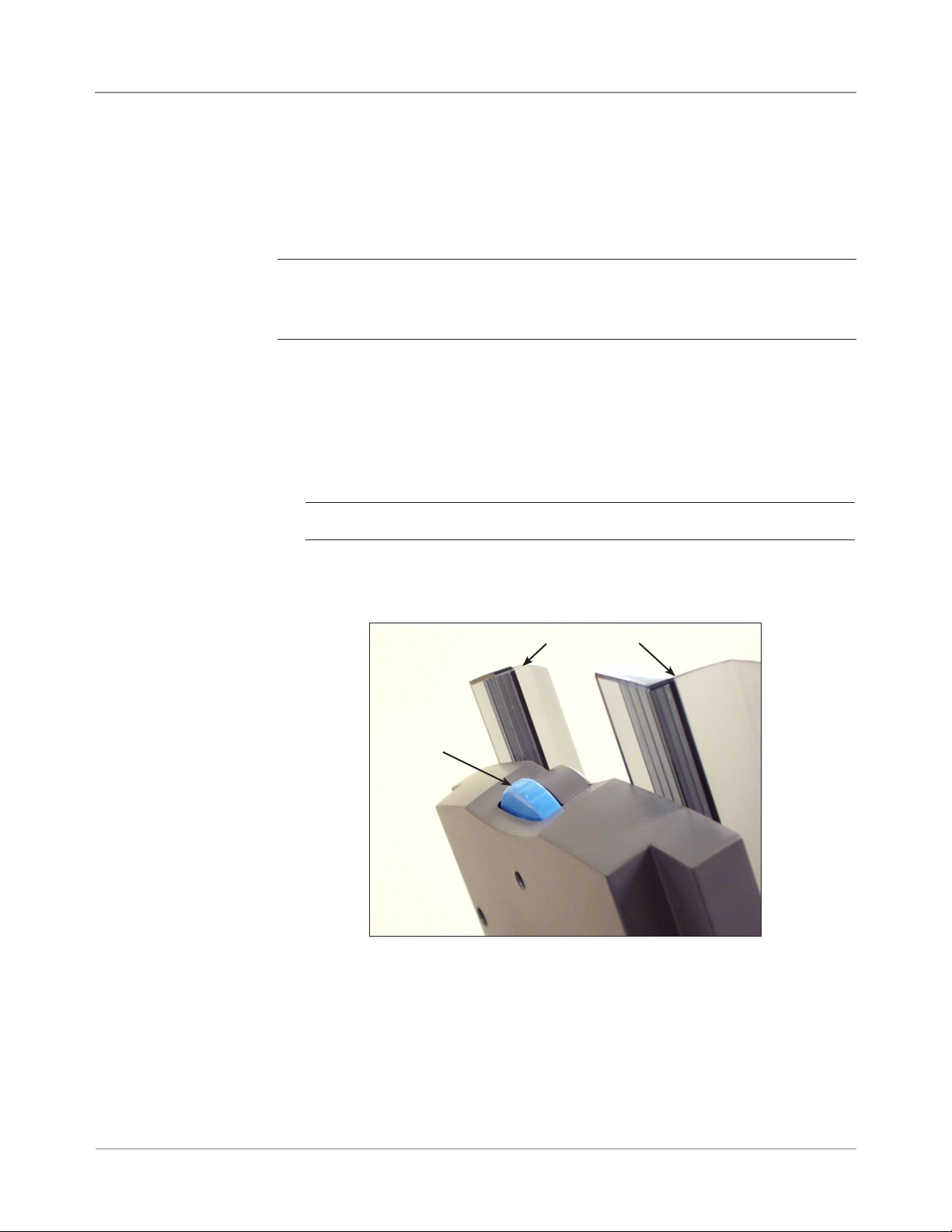
To load envelopes into the HCEF, you will need to adjust the Side Guides,
Wedge, and Separator Gap. Before you begin making any adjustments, fan
a stack of envelopes and remove any that are nested, curled, or damaged in
any way.
NOTE: To view a demo of the Wedge (wedge) and Separator Gap adjustment
processes, go to the Home screen. Select “Loading Instructions and Pre-Run
Adjustments”. Use the UP/DOWN arrow keys to select the envelope being fed by
the HCEF, then select “Feeders Setup Demo”.
Adjusting the HCEF Side Guides
1. Place an envelope between the Side Guides.
2. Using the Adjustor knob, bring the Side Guides in to lightly touch the envelope.
3. Release the knob. The Guides will spring back to the correct position to
allow free sliding of the envelope between the Side Guides.
NOTE: Side Guides only spring back after they are moved inward.
4. Make sure the envelope slides freely between the Side Guides when it is
placed flat on the red feed belts.
Side Guides
Adjustor
Figure 3.6: Adjusting the HCEF Side Guides
SV61311 Rev. E
3-13
Page 56

3 • Basic Operation
Loading the
DI950 HCEF
(continued)
Adjusting the HCEF Wedge
1. Insert an envelope into the HCEF with the bottom edge of the envelope
against the Center Guide, in line with the two screws. The top edge of
the envelope (edge with flap) should point towards the Wedge.
NOTE: Ensure the envelope is centered, not angled, on the Center Guide
to obtain correct positioning. If the position of the envelope is incorrect, the
Separator Gap adjustment will be incorrect as well.
2. Push up and release the blue Wedge Locking Lever.
3. Slide the Wedge toward the envelope, until the top edge of the envelope
fits into the center slot of the Wedge.
Wedge
Wedge
Locking
Lever
Center Guide
Figure 3.7.1: Adjusting the Wedge Position
3-14 SV61311 Rev. E
Page 57

Loading the
DI950 HCEF
(continued)
Basic Operation • 3
Figure 3.7.2: Corner of Envelope in Center Slot
4. Push down on the Trail Prop Locking Lever to lock the Wedge into place
and remove the envelope.
SV61311 Rev. E
3-15
Page 58

3 • Basic Operation
Loading the
DI950 HCEF
(continued)
Adjusting the HCEF Separator Gap
NOTE: You must adjust the HCEF Wedge before you can adjust the Separator
Gap. Refer to Adjusting the HCEF Wedge in this chapter for more information.
1. Prepare an envelope for the separator gap adjustment:
a. Cut a strip of 20 lb. (75 gsm) paper to fit inside an envelope.
b. Insert the strip of paper into the envelope.
NOTE: Tap the envelope lightly against a hard surface to ensure the strip
of paper rests all the way down at the bottom of the envelope.
c. Close the envelope flap.
2. Push up on the Separator Gap Lever to raise the Separator.
Figure 3.8.1: Push up on the Separator Gap Lever
Figure 3.8.2: Separator, Raised.
3-16 SV61311 Rev. E
Page 59

Basic Operation • 3
Loading the
DI950 HCEF
(continued)
2. Place the envelope, bottom edge
first, into the Separator so the top
edge (flap crease) lines up with the
edge of the tab on the Wedge.
NOTE: The edge of the tab is indicated by two arrows.
3. Lower the Separator completely,
then push down on the Separator
Gap Lever to lock it into place.
4. Pull the envelope out from the
HCEF.
SV61311 Rev. E
Figure 3.8.3: Envelopes Lined Up with Tab on
Wedge.
5. Shingle a 20mm to 50mm stack of envelopes. Place the envelopes into
the HCEF flap side down, flap last.
6. Finish loading a full stack of envelopes (up to 500 pieces), making sure
that the envelopes contact the back of the Side Guides. It is not necessary to shingle the remaining envelopes.
NOTES:
• If an HCSF or Attached Printer is present, you may need to adjust guides to
ensure sheets feed correctly. Refer to Adjusting the HCSF Guides or Adjust-
ing the Printer Interface Guides in Chapter 7 of this guide for more information.
• If you are using scanning, you may need to adjust the scan head to ensure
the bar code or OMR mark is read. Refer to Adjusting the Scan Heads in
Chapter 8 of this guide for more information.
3-17
Page 60

3 • Basic Operation
Making Pre-Run Adjustments
Adjusting the Envelope Openers
Once you have loaded the items for the selected job, you may need to make
some envelope opener adjustments to ensure job accuracy.
The Envelope Openers in the Insertion Area open each envelope to allow
insertion of the contents. If you are using a different size envelope than the
previous job, you need to confirm that the envelope aligns properly with the
Openers before running the new job. If the alignment is incorrect, you need
to adjust the position of the Envelope Openers. Follow the steps in this section below to verify envelope alignment and to make adjustments.
Feed a Test Envelope
1. Load the outer envelopes into the envelope feeder(s).
2. Select "Loading Instructions" from the Home screen, and then select
"Pre-Run Adjustments", and finally select "Envelope Opener Settings".
NOTE: The system will automatically select the Feeder when only one outer
envelope is being used. If multiple outer envelopes are to be used, you need
to select an envelope Feeder.
3. Press TRIAL PIECE to feed one envelope to the Insertion Area.
4. Open the Insertion Area Cover and observe the Envelope. If you need
to make adjustments, follow the procedures for setting the width and/or
length, as stated next.
Open the Insertion
Area Cover
Figure 3.9.1: Insertion Area Cover
3-18 SV61311 Rev. E
Page 61

Basic Operation • 3
Adjusting
the Envelope
Openers
(continued)
Perform Width Adjustments (Outer Envelope Openers)
1. Loosen the thumbscrews on the top of the Outer Envelope Openers.
Outer Envelope
Opener
Thumbscrews
Figure 3.9.2: Outer Envelope Opener Locations
2. Slide the Openers as required to align the pointers with the outer edges
of the envelope.
• Push down on the thumbscrews to ensure the Outer Envelope Open-
ers align with the envelope.
• If using small envelopes (less than 194mm wide), move the Outer
Envelope Openers out and away from the outer edges of the envelope.
• If using windowed envelopes, ensure the Outer Envelope Openers
do not touch the edges of the window.
SV61311 Rev. E
Align pointer with outer
edge of envelope
Figure 3.9.3: Aligning the Outer Envelope Opener
3. Tighten the thumbscrew on the top of the Outer Envelope Operners.
3-19
Page 62

3 • Basic Operation
Adjusting
the Envelope
Openers
(continued)
Perform Length Adjustments (Inner Envelope Openers)
1. If using windowed envelopes, loosen the thumbscrews that secure each
Inner Envelope Opener.
NOTE: There are three Inner Envelope Openers, that typically need length
adjustments only. But, when needed, these (except the Middle Opener) can
be moved laterally.
Inner Envelope
Opener
Thumbscrews
Figure 3.9.4: Inner Envelope Opener Locations
a. Position the Inner Envelope Openers so they do not touch the edge
of the window. In unusual circumstances, i.e., vertical windows, it
may be necessary to place the Opener on the window to prevent the
Opener from catching on the window's edge.
b. Tighten the thumbscrews for the adjusted Openers.
2. Press down then pull one of the knobs on the top of the frame to determine how far the the insertion edge of one Inner Envelope Opener goes
into the envelope.
3-20 SV61311 Rev. E
Page 63

Basic Operation • 3
Adjusting
the Envelope
Openers
(continued)
3. If necessary, loosen the knob on the insertion edge of the Inner Envelope Opener, and adjust until it goes at least 5 mm into the top panel of
the envelope.
Insertion Edges of Inner
Envelope Openers
Figure 3.9.5: Inner Envelope Openers Inserted into Envelope
4. Tighten the knob for the adjusted insertion edge.
5. Repeat steps 2 through 4 for the other two insertion edges.
Verify Settings
When you finish making the necessary Envelope Opener adjustments, close
the Insertion Area Cover, then verify your settings by doing the following:
1. Press CLEAR DECK.
2. Press TRIAL PIECE.
• If the Envelope Openers are positioned correctly (that is, aligned cor-
rectly to open the envelope), select "OK".
• If more adjustments are needed, repeat the steps stated in the previ-
ous sections until proper alignment is achieved.
NOTE: Each time you press TRIAL PIECE, a complete Trial Piece will be
generated.
SV61311 Rev. E
3-21
Page 64

3 • Basic Operation
Running a Trial Piece
Once the job setup is completed, you must run a trial piece to ensure system function and to verify the accuracy of your final mail piece. Follow these
steps to run a trial piece:
1. Attach the Feeder Trays to the Feeder Tower. Refer to earlier sections in
this chapter for specific instructions.
NOTE: Highlight the Mail Piece Tree Icons on the Home screen for information on the Tray type to use, orientation of the material in the Tray, and location of the Tray on the Feeder Tower.
2. Load the mail piece components into the Feeder Trays.
3. Press TRIAL PIECE. The system collates all contents of the mail piece
according to the job parameters. The resulting mail piece is fed to the
Upper Divert Area waiting for your inspection. It does not go through the
Sealer. The Trial Piece Complete screen will display.
4. Examine the mail piece:
a. Remove the contents from the outer envelope.
b. Make sure the items are collated in the desired order and that the
destination address displays correctly, in the case of a windowed
enveloped.
c. Check for doubles.
3-22 SV61311 Rev. E
Page 65

Basic Operation • 3
Running a
Trial Piece
(continued)
5. Depending on your findings, choose one of the following options listed
on the Trial Piece screen:
a. If the trial mail piece passes inspection, select “Trial Piece OK”. You
will be returned to the Home screen, or press START to begin the
job.
b. If the address needs to be moved UP/DOWN (applies to Windowed
envelopes), select “Adjust Address”. The following screen will appear.
Press to adjust.
mm
3
A
B
ABC Company
C
36 Waterview Dr.
Derby, CT 12345
SV61311 Rev. E
Accept
Adjust Address Screen
• Use the UP/DOWN keys to re-position the address, and then select "Finished". You will be returned to the Home screen.
c. If you want to make other adjustments, select “Edit Job”. You will
now be able to add, delete, or move mail piece components and to
change parameters for a document(s) in the mail piece.
NOTES:
• Detailed instructions on use of the Add, Delete, Move, and Edit functions are contained in later sections of this chapter.
• If you make any changes to the mail piece order, address position
and/or to a document(s) in the mail piece, run Trial Piece again to
verify machine function and mail piece accuracy.
• Any edits you make are NOT saved unless a Supervisor/Manager
specically saves them.
d. If you need to check/verify the job settings, access the Review Job
screen (select "Home", then select "Menu", "Jobs" and finally "Review Job").
3-23
Page 66

3 • Basic Operation
Reviewing the Job Settings
You may want to review the job settings before you start running the job.
The Review Job screen provides an at-a-glance view of the settings for
each of the mail piece component parameters and the general job settings.
This screen is a time efficient way to make sure that you have selected the
correct job.
Review Job
Job: 123
Press to review more job items.
Job Items
Job Settings
Job Type
Batch Mode
Batch Count
Maximum Count
Last Run
Use Postage Meter
Job Comments
Custom Job
On
100
Divert
03/06 - 14:56
No
THIS FIELD HAS
SPACE FOR 120
CHARACTERS
(MAX.)
Edit Job
Finish
Review Job Screen
To access the Review Job screen:
1. From the Home screen, select "Menu".
2. From the Menu screen, select "Jobs", then "Review Current Job".
3. Use the Arrow Keys to scroll through the settings for the job and each of
the included items.
• Select "Edit Job" to access screens for making changes.
• Select "Finish" to return to the Menu screen.
• Press HOME to return to the Home screen.
NOTE: Make sure that the materials in the mail piece meets material specications. Refer to the Specications listed in Chapter 6.
3-24 SV61311 Rev. E
Page 67

Basic Operation • 3
Starting the Job
SwiftStart
™
Jobs
When your Trial Piece is verified, you are ready to start running the job. To
do this:
1. Make sure that you are in the Home screen.
2. Press START. The system will begin running the job.
SwiftStart™ mode allows you to run a simple job without entering any setup
information. In SwiftStart™ mode, the system automatically senses the material and sets the required parameters for running the job. A SwiftStart™ job
can be run without saving the settings, or a Supervisor/Manager can name
and save the job for future recall and use.
Use SwiftStart™ when your mail piece consists of only a small number of
sheets of one size that can be folded.
• A single sheet and a single insert will be taken from each loaded feeder,
giving a maximum mail piece content of: four sheets and three inserts
(DI900) or four sheets and four inserts (DI950). Fold will be determined
by sheet length and envelope depth.
NOTE: The maximum content options are available only when two HCSFs
are present.
• Maximum sheet length is 11-5/8" (297 mm)
• Only envelope depths of 4-1/4" to 6-3/8" (109 mm, 111 mm, 114 mm,
121 mm and 162 mm) can be used.
• Cannot be used to run fold only or inserts only.
• Cannot link feeders in this mode.
• Envelope sealer is always on (except on trial piece).
• Batch count is always off.
• This mode will not work with scanning.
• Address should be at the top of the sheet.
SV61311 Rev. E
3-25
Page 68

3 • Basic Operation
Using SwiftStart™
To use SwiftStart™:
1. Select "SwiftStart" from the Home screen.
2. Attach and load Feeder Trays:
a. Load the outer envelopes in Insert Tray (A) or in the HCEF (G, if
present on system).
b. Load sheets and then inserts, starting with the feeder farthest to the
left and on the bottom.
c. Load the remaining sheets and/or inserts clockwise and to the right
of the first item.
3. Press TRIAL PIECE. The system feeds one envelope from the Insert
Tray or HCEF (if present), and measures its length. Then, it feeds a
sheet from the Sheet Tray and measures its length. The system does
some internal calculations with these measurements and from them determines the fold type for the control document.
The system then repeats the measuring and fold determination proce-
dure for each sheet and insert, creating a Mail Piece Icon Tree in the
process to represent this job.
When all items from loaded Trays/Feeders have been fed, the system
produces a sample mail piece.
4. Check the trial piece, and then make any needed adjustments. Repeat
the trial piece run until the mail piece meets your specifications.
5. Press START to run your job.
6. If you wish to save this job, you will need supervisor or manager access
to enter a name in the save job screen.
Creating a Job
3-26 SV61311 Rev. E
Creating a new job involves defining the contents of a new mail piece, and
optionally, saving the job for future use. This process consists of identifying
each item in the mail piece and selecting settings for the job. A Mail Piece
Icon Tree automatically builds on the screen as you add items.
To access the Create New Job screen:
1. From the Home screen, select “Menu”, then “Jobs”, and finally “Create
New Job.” The Create Job screen displays.
2. Enter the Job Name using the alphanumeric matrix.
a. Use the UP/DOWN and LEFT/RIGHT arrow keys to select a letter.
b. Press OK to add the letter to the job name. Highlight the arrow char-
acter and press OK to move the cursor within the job name.
c. Select “Accept Name” when done.
Page 69

Basic Operation • 3
Creating a Job
(continued)
3. If scanning is present on the system, the Create - Job Type screen displays.
• If the new job does not require scanning, select "Normal Type" to
continue.
• If the new job requires scanning, select "Scanning Job".
4. The Create Outer Envelope screen displays.
• If the job does not require an Outer Envelope, select "No".
• If the job requires an Outer Envelope, select “Yes.”
- Select the appropriate Outer Envelope options for the job. Refer
to the Envelope Options table in this chapter for more information
about each of the related menu options.
- Press “Accept” when done.
- If the job is a scanning job, the Create - Only One Envelope
screen displays. If the job requires only one envelope, select
"Yes" and proceed to step 5.
If the job requires an additional envelope, select "No, Two Outer
Envelopes". Validate the available options, and press "Accept"
when done.
NOTE: If this is a scanning job, and you will be using dynamic envelope selection, you must select “No, Two Outer Envelopes”.
5. The Create - Select Next Item screen displays. Select the appropriate
option.
Menu Options Associated Options/Actions
Reply Card
Reply Envelope
Pre-Folded Insert
Small Booklet
Slip
Generic Insert
Large Booklet
a. If this is a scanning job, follow the steps below. Otherwise, go
to step b.
• The Scan Type screen displays. Select the appropriate
Scan Type (OMR, Code 3 of 9, or Interleaved 2 of 5.)
• The Scan Configuration screen displays. Select the
appropriate Scan Configuration.
• The Content - In Line with Marks screen displays. If there
is content in line with the scan marks, select "Yes". If there
is no content in line with the scan marks, select "No".
b. Select the appropriate options for the insert. Press “Accept”
when done.
Refer to the Insert Options table in this chapter for specific
information about each of the related menu options.
SV61311 Rev. E
3-27
Page 70

3 • Basic Operation
Creating a Job
(continued)
Menu Options Associated Options/Actions
Sheet (continued) a. Follow the appropriate step below:
• If this is the first sheet you are adding to the job and the
Attached Printer is not present select the appropriate
personalization option. The Create - Verify Sheet screen
appears.
• If this is the second sheet you are adding to the job select
either "Same Set (Fold with previous sheet)" or "New Set
(Fold separately.)" If the sheet is part of a new set, select
the appropriate personalization option.
• If this is the first sheet you are adding to the job and the
Attached Printer is present select the appropriate printer
option. The Sheet - Personalized Create screen appears.
Select the appropriate personalization option. The Create
- Verify Sheet screen appears.
b. If this is a scanning job, follow the steps below. Otherwise, go
to step c.
• The Scan Type screen displays. Select the appropriate
Scan Type (OMR, Code 3 of 9, or Interleaved 2 of 5.)
• The Scan Configuration screen displays. Select the
appropriate Scan Configuration.
• The Content in Line with Marks screen displays. If there is
content in line with the scan marks, select "Yes". If there is
no content in line with the scan marks, select "No".
• If you selected "Yes", the Mark Locations Settings screen
appears. Follow the steps below to enter the various
mark-related measurements:
- Select an option, then use the UP/DOWN arrow keys
to enter the appropriate measurement (in millimeters).
- Press "Accept" when done entering the
measurement.
- Once all measurements have been entered, select
"Accept".
c. Select the appropriate Sheet options for the job. Press
"Accept" when done.
NOTE: If this is a scan job, be sure to set the Select Feed
setting.
Refer to the Sheet Options table in this chapter for more
information about each of the related menu options.
d. Select the appropriate Fold options for the sheet. Press
"Accept" when done.
Refer to the Fold Options table in this chapter for specific
information about each of the related menu items.
6. Once you have finished adding a Sheet or Insert, the Add New Item
screen appears.
• Select "Yes" to add additional items to the job. Repeat step 4 as nec-
essary.
• Select "No" if you have finished adding items to the job.
7. The Create - Edit Job Settings screen displays. Select the appropriate
options.
3-28 SV61311 Rev. E
Page 71

Basic Operation • 3
Creating a Job
(continued)
Menu Options Associated Options/Actions
Job Comments Use the alphanumeric matrix to enter any additional information
related to the job. If the job will be saved by a supervisor or
manager, you can make it easy for operators to identify/select the
correct job in the future by entering a job description in the job
comments area.
NOTE: Job comments can contain up to 120 characters.
Batch Mode Toggle:
• Off means this feature will not function for this job, or
• On means this feature is active.
NOTE: Batch mode cannot be used with scanning jobs.
Batch Count Use the numeric matrix to enter the batch count value.
NOTE: The batch count can contain up to four digits. The
minimum is "5" and the maximum is "9999".
Set Over Max Count Indicates what will happen to sets that exceed the set over count
quantity. Choices include Divert and Stop.
Use Postage Meter Select this option if you will be using the Mail Machine Interface
(MMI). This interface enables communication between the Inserting
System and either a DM Series™ DM800i™ or DM1000™ mailing
system via a USB connection.
The system sends start and stop signals to the mailing system, and
the mailing system can send error messages back to the inserter to
stop feeding.
Toggle:
• Off means this feature will not function for this job, or
• On means this feature is active.
NOTE: The MMI is a purchasable exit option. Only letter-sized
envelopes can be used with this interface.
Refer to DM Series™ Mailing System Interface (DM800i™ or
DM1000™ only) in Chapter 7 for more information about the MMI.
Advanced Allows access to advanced job settings.
IMPORTANT: Do not change the advanced job settings unless
instructed to do so. Changing settings may affect machine
performance.
SV61311 Rev. E
8. Select "Accept" when done.
9. The Create - Saved Created Job screen displays.
• Select "Yes, Save" to save the job (optional). You must have supervisor or manager access rights to save jobs.
• Select "No, Save Later" if you do not have supervisor or manager
access rights.
3-29
Page 72

3 • Basic Operation
Job Options
Envelope Options
This section contains descriptions of the various options you can add or
modify when creating or editing a job.
Menu Item Associated Options and Actions
Name Use the alphanumeric matrix to enter the envelope name.
Size refers
specifically to the
outer envelope that
contains the final
mail piece.
Window allows use
of windowed or nonwindowed envelope.
Type allows choice of
windowed envelope.
Seal refers to using
the Moistener unit to
close the envelope.
Depth is the
dimension of an
envelope from its flap
fold to its opposite
edge.
Toggle:
• Letter generally has smaller depth and contains folded sheets,
or
• Flat generally is larger than Letter size and typically contains
unfolded sheets.
Refer to Envelopes in Chapter 6 for specification information.
Toggle:
• Yes means you are using a windowed envelope, or
• No means you are using a non-windowed envelope.
• Standard Flap is a regular envelope.
• Forward Flap means the window and flap are on the same
side of the envelope.
• Bottom Flap means the flap is at the bottom (instead of the
top) of the envelope.
• Off means the envelope will not be sealed closed, or
• On means the envelope will be sealed closed.
• Safe Seal means the envelope will be sealed closed. However,
the envelope moves through the system at a slower rate to
provide more time for better sealing. This option is available
only for flat envelopes, when the Flats Sealer is present on the
system.
NOTE: If you are using a mailing machine in-line with the inserting
system, you must instruct the system to seal the envelope.
• Auto Measure - system measures depth when envelope is fed.
• Custom Depth - allows you to enter the depth of the envelope.
• Letter Options: #10 - 105mm, #6 ¾ - 165mm, C5 - 162mm,
C6 - 114mm. Flat Options: #12 ½ - 317mm, C4 - 229mm.
3-30 SV61311 Rev. E
Page 73

Basic Operation • 3
Envelope
Options
(continued)
Menu Item Associated Options and Actions
Additional Settings Double Detect allows the system sense when multiple envelopes
are fed unintentionally.
• Double Detect Feature allows you to toggle:
- Off means this feature will not function for this item, or
- On means this feature is active.
• Location allows you to toggle:
- Default, or
- Custom.
• Custom Location for Top Edge allows you to enter a specific
measurement (distance from the edge feeding first into the
feeder) where the system should attempt to detect a double.
Set this option when Location is set to "Custom".
- Use the UP/DOWN arrow keys to adjust the measurement
(in millimeters).
- Select "Accept" when you are done.
NOTE: The double detect region cannot be within 25 mm of
the lead or trail edges of the envelope.
If the envelope is feeding from the HCEF, measure from the
bottom of the envelope.
If the envelope is feeding from the Feeder Tower, measure
from the top of the envelope. The custom location must be at
least 5 mm away from the edge of the window (if present), at
least 5 mm away from the edge of flap, and cannot lie on top
of a seam.
For best results, be sure to avoid areas that overlap with the
window, flap, or seams.
• Action On Double allows you to select where the items should
be fed to if a double is detected.
Feeder Type allows you to change the Feeder setting when
material is problematic.
• Normal is used for most items.
• Special Feeder helps problematic material run better.
NOTE: The Special Feeder is a purchasable option. If available,
it will be located at the top left or right of the Feeder Tower. It is
an option for one or more tower feeders to improve feeding of
thin prefolded items or booklets with thin covers. It reduces the
tendency of these items to separate while they are being fed. You
must push the “Special Feeder” lever up to run a job when the
Feeder Type is set to Special Feeder.
Feeder Linking allows multiple Feeders to feed the same
envelope.
• None means there is no linking of Feeder Trays.
• Two Feeders indicates that two Feeder Trays are linked and
feeding the same material.
NOTE: Feeders must be on the same module and on the same
side of the tower to be linked. For scanned items, always load
linked feeders at a collation break.
SV61311 Rev. E
3-31
Page 74

3 • Basic Operation
Envelope
Options
(continued)
Fold Options
Menu Item Associated Options and Actions
Additional Settings
(continued)
Menu Item Associated Options and Actions
Fold Type refers
to the way sheets
are folded to be
able to show certain
portions through a
window, and/or when
a sheet is opened.
Envelope Select Feed allows you to indicate when the envelope
should be used.
Toggle:
• Main
• Alternate
NOTE: This option is enabled only when the Scan feature is
activated, two Outer Envelopes have been defined in a job and
either one of the following:
• The Item Over Count Action is set to “Use Alternate Envelope”
on the control document in the job, OR
• An Envelope Select mark is contained in the scan
configuration file associated with the control document in the
job.
• C Fold
• Z Fold
• Single Fold
• Double Fold
Auto Fold Lengths
lets the system
choose the type of
fold.
Fold 1 Length
Fold 2 Length
• No Fold
Toggle:
• Yes means the system calculates the fold length, or
• No means you will enter the fold lengths you want.
Fold Length is shown on the display screen for each fold type/
address combination.
• Use the UP/DOWN Arrow Keys to select desired length.
• Press "Accept" when done.
3-32 SV61311 Rev. E
Page 75

Basic Operation • 3
Sheet Options
Menu Item Associated Options and Actions
Name Use the alphanumeric matrix to enter the job name.
Control Document
is the top sheet in
the Mail Piece Icon
Tree. This field is
read-only.
Type identifies the
printing source of the
job.
Personalized refers
to the top sheet that
contains the address
that will show in the
windowed envelope
and/or a sheet that
contains information
customized to a
specific recipient.
Quantity is the
number of this type
of sheet to include in
each mail piece.
Page Order
identifies the feeding
pattern of multiple
sheets that are not
identical.
Length is the
dimension of the
sheet in the direction
of the feed.
Read-Only field
• Yes, or
• No
• Printed Separately - indicates the sheet is not printed by the
Attached Printer.
• Printed by Attached Printer - indicates the sheet is printed by
the Attached Printer.
NOTE: This menu option is available only with configurations that
contain an Attached Printer. If an Attached Printer is not present,
this option appears as a read-only field with “Printed Separately” as
the default setting.
• Top Address
• Middle Address
• Bottom Address
• Not Personalized
• Personalized - No Address
• 1, 2, 3, 4, 5, 6
• Custom Quantity
- Use UP/DOWN arrows to select number.
- Select "Accept" when done.
NOTE: Quantity is always set to Variable (n) for scanning jobs.
Forward - indicates page 1 is on top and pages 2, 3, 4, etc. follow in
that order.
Reverse - indicates that the last page, for example, page 4, is first
followed by pages 3, then 2, then 1.
NOTE: This menu option appears as a read-only field when the
job requires a Custom Feeder. The feeding pattern is set by the
Custom Feeder.
• Auto measure - measures the recommended length
automatically.
NOTE: This menu option appears as a read-only field when
the job requires a Custom Feeder.
• Custom Length - allows increase or decrease of sheet length.
- Use UP/DOWN arrows to select number.
- Select "Accept" when done.
• Letter - 279mm, Legal - 356mm, and A4 - 279mm are
additional options.
NOTE: The “Legal” option is not available when the sheet
is printed by the Attached Printer. Additionally, legal-sized
documents cannot be fed from the High Capacity Sheet
Feeder. The system will assign these documents to a Tower
Feeder, even when the High Capacity Sheet Feeder is
available.
SV61311 Rev. E
3-33
Page 76

3 • Basic Operation
Sheet Options
(continued)
Menu Item Associated Options and Actions
Additional Settings. Double Detect allows the system to sense when multiple sheets
are fed unintentionally.
NOTE: This menu option is not available when the job requires a
Custom Feeder.
• Double Detect Feature allows you to toggle:
- Off means this feature will not function for this item, or
- On means this feature is active.
• Location allows you to toggle:
- Default, or
- Custom.
• Custom Location for Top Edge allows you to enter a specific
measurement (the distance from the edge feeding first into the
feeder) where the system should attempt to detect a double.
NOTE: Set this option when Location is set to "Custom". The
double detect region cannot be within 25 mm of the lead or trail
edges of the sheet.
- Use the UP/DOWN arrow keys to adjust the measurement
(in millimeters).
- Select "Accept" when you are done.
• Action On Double allows you to select where the items should
be fed to if a double is detected.
Feeder Type allows you to change the Feeder setting when
material is problematic, or to indicate that the job requires a Custom
Feeder.
NOTE: This menu option is not available when the job requires an
Attached Printer.
• Normal is used for most items.
• Manual Feed is used when items will be fed into the system
by hand. Refer to Manual Feeder in Chapter 2 for more
information.
• Custom Feeder is used when items will be fed into the system
by the Custom Feeder.
Feeder Linking allows multiple Feeders to feed the same material.
NOTE: This menu option is not available when the job requires a
Custom Feeder or an Attached Printer.
• None means there is no linking of Feeder Trays.
• Two Feeders indicates that two Feeder Trays are linked and
feeding the same material.
NOTE: Scanned sheets can be linked vertically in both the High
Capacity Sheet Feeder and the Feeder Tower.
Scan Items allows you to indicate whether or not an item should be
scanned.
Toggle:
• Yes means this feature is active, or
• No means this feature will not function for the item.
3-34 SV61311 Rev. E
Page 77

Basic Operation • 3
Sheet Options
(continued)
Menu Item Associated Options and Actions
Additional Settings
(continued)
Scan Settings
NOTE: The “Content in Line with Marks”, “Marks On”, “Marks on
First Page Only”, and “Mark Location Settings” options are not
available when the job requires a Custom Feeder.
• Scan Configuration allows a choice of saved scan
configurations to interpret scan marks.
• Content in Line with Marks indicates that content is in line with
the scan marks in the feed direction.
• Marks On indicates if marks are on the front or back of the
page.
• Marks on First Page Only indicates marks are on only the first
of multiple sheets.
• Mark Location Settings allows setup of various mark-related
measurements.
- Top of Page to First Mark is the distance from the top of
the page to the first mark.
- Total Length of Marks is the length from the top of the first
possible mark to the bottom of the last mark.
- Top of Page to Clear Zone is distance from the top of the
page to the beginning of the Clear Zone.
- Length of Clear Zone is the distance from the top of the
Clear Zone to the first mark.
Refer to OMR Specifications in Chapter 8 for more information
on the Clear Zone and mark location settings.
• Item Over Count Quantity is the number of sheets to be
accumulated before the system takes an alternate action.
• Item Over Count Action indicates what will happen to items that
exceed the item over count quantity. Choices include:
- Divert – Select this option if the Scan Configuration does
not have the Divert Sheet (DVS) scan mark, and you
want the system to divert items once the item over count
quantity has been exceeded.
- Stop - Select this option if you want the system to stop
processing items once the item over count quantity has
been exceeded.
- Use Alternate Envelope – Select this option if the Scan
Configuration does not have the Envelope Select (ES)
scan mark, and you want the system to use an alternate
envelope for items that exceed the item overcount quantity.
Refer to Scanning Features in Chapter 8 for more information
on dynamic envelope selection and divert sheet functionality.
Select Feed (SF) Settings allows assignment of a Feeder to one of
the 9 Select Feed scan marks.
NOTE: This menu option is not available when the item requires an
Attached Printer or Custom Feeder (when a High Capacity Sheet
Feeder is part of the configuration).
SV61311 Rev. E
3-35
Page 78

3 • Basic Operation
Insert Options
Menu Item Associated Options and Actions
Name Use the alphanumeric matrix to enter the job name.
Insert Type includes
all items that do not
need folding or have
been pre-folded.
Personalized
means the insert
contains information
customized to a
specific recipient.
NOTE: This menu
option is not available
when “Large Booklet”
is the selected insert.
Quantity is the
number of this
particular insert to
include in each mail
piece.
NOTE: This menu
option is not available
when “Large Booklet”
is the selected insert.
Page Order identifies
the feeding pattern of
multiple inserts that
are not identical.
NOTE: This menu
option is not available
when “Large Booklet”
is the selected insert.
Length is the
dimension of the
insert in the direction
of the feed.
• Reply Envelope - is also called a Business Reply Envelope.
• Reply Card - is a thick slip.
• Pre-folded Insert - is a sheet or set of sheets already folded
together.
• Small Booklet - is a type of insert that typically has a bound or
stapled edge.
• Slip - is single thickness document that fits into the outer
envelope without folding.
• Generic - is an undeclared type of insert used by SwiftStart™
jobs.
• Large Booklet - is a type of insert that typically has a bound or
stapled edge.
Yes means there is unique information on this insert, or
No means the insert does not contain unique information.
• 1, 2, 3, 4, 5, 6
• Custom Quantity
- Use UP/DOWN arrow keys to select number.
- Select "Accept" when done.
• Variable - used with scanning-controlled jobs.
NOTE: At this time, only a single insert can be added to each
mail piece. When using a flat envelope, the insert must be a Reply
Envelope (BRE).
Forward - indicates page 1 is on top and pages 2, 3, 4, etc. follow
in that order.
Reverse - indicates that the last page, for example, page 4, is first
followed by pages 3, then 2, then 1.
• Auto measure - measures the recommended length
automatically.
NOTE: Auto measure is not available when “Large Booklet” is
the selected insert or when the job requires a Custom Feeder.
• Custom Length - allows increase or decrease of insert length.
- Use the UP/DOWN Arrow Keys to select number.
- Select "Accept" when done.
• Custom Length (Large Booklet Only) - allows selection of large
booklet size: 8.5” x 11” or 5.5” x 8.5”.
3-36 SV61311 Rev. E
Page 79

Basic Operation • 3
Insert Options
(continued)
Menu Item Associated Options and Actions
Additional Settings Double Detect allows the system sense when multiple inserts are
fed unintentionally.
NOTE: This menu option is not available when the job requires a
Custom Feeder.
• Double Detect Feature allows you to toggle:
- Off means this feature will not function for this item, or
- On means this feature is active.
• Location allows you to toggle:
- Default, or
- Custom.
• Custom Location for Top Edge allows you to enter a specific
measurement (the distance from the edge feeding first into the
feeder) where the system should attempt to detect a double.
NOTE: Set this option when Location is set to "Custom". The
double detect region cannot be within 25 mm of the lead or trail
edges of the insert.
- Use the UP/DOWN arrow keys to adjust the measurement
(in millimeters).
- Select "Accept" when you are done.
• Action On Double allows you to select where the items should
be fed to if a double is detected.
Feeder Type allows you to change the Feeder setting when
material is problematic, or to indicate that the job requires a Custom
Feeder.
NOTE: This menu option is not available when the job requires an
Attached Printer.
• Normal is used for most items.
• Manual Feed is used when items will be fed into the system
by hand. Refer to Manual Feeder in Chapter 2 for more
information.
• Custom Feeder is used when items will be fed into the system
by the Custom Feeder.
Feeder Linking allows multiple Feeders to feed the same material.
NOTE: This menu option is not available when the job requires a
Custom Feeder.
• None means there is no linking of Feeder Trays.
• Two Feeders indicates that two Feeder Trays are linked and
feeding the same material.
Scan Items allows you to indicate whether or not an item should be
scanned.
Toggle:
• Yes means this feature is active, or
• No means this feature will not function for the item.
SV61311 Rev. E
3-37
Page 80

3 • Basic Operation
Insert Options
(continued)
Menu Item Associated Options and Actions
Additional Settings
(continued)
Scan Settings
NOTE: The “Content in Line with Marks”, “Marks On”, “Marks on
First Page Only”, and “Mark Location Settings” options are not
available when the job requires a Custom Feeder.
• Scan Configuration allows choice of saved scan configurations
to interpret scan marks.
• Content in Line with Marks indicates that content is in line with
the scan marks in the feed direction.
• Marks On indicates if marks are on the front or back of the
page.
• Marks on First Page Only indicates marks are on only the first
of multiple inserts.
• Mark Location Settings allows setup of various mark-related
measurements.
- Top of Page to First Mark is the distance from the top of
the page to the first mark.
- Total Length of Marks is the length from the top of the first
possible mark to the bottom of the last mark.
- Top of Page to Clear Zone is distance from the top of the
page to the beginning of the Clear Zone.
- Length of Clear Zone is the distance from the top of the
Clear Zone to the first mark.
Refer to OMR Specifications in Chapter 8 for more information
on the Clear Zone and mark location settings.
• Item Over Count Quantity is the number of inserts that cannot
be run normally.
NOTE: At this time, only a single insert can be added to each
mail piece. When using a flat envelope, the insert must be a
Reply Envelope (BRE).
• Item Over Count Action indicates what will happen to items
that exceed the item over count quantity. Choices include:
- Divert - Select this option if the Scan Configuration does
not have the Divert Sheet (DVS) scan mark, and you
want the system to divert items once the item over count
quantity has been exceeded.
- Stop - Select this option if you want the system to stop
processing items once the item over count quantity has
been exceeded.
Refer to Scanning Features in Chapter 8 for more information
on divert sheet functionality.
Select Feed (SF) Settings allows assignment of a Feeder to one
of the 9 Select Feed scan marks.
NOTE: This option is not available if the item requires a
Custom Feeder and a High Capacity Sheet Feeder is part of the
configuration.
3-38 SV61311 Rev. E
Page 81

Basic Operation • 3
Editing a Job
Editing a job involves any or all of the following:
• Changing characteristics for a selected item.
• Adding an item to the mail piece.
• Deleting an item from the mail piece.
• Moving an item to a different position in the mail piece collation.
• Modifying settings for the job.
Edit Job
Press to highlight an item to edit.
Job Items
A
B
C
D
Edit Job Settings
Edit Highlighted Item
Move Highlighted Item
Delete Highlighted Item
Add New Item
Job: 123
Finished
Edit Job Screen
NOTE: The options available in the Edit Job screen vary and depend on the item
selected and the number of available Trays on the Feeder Tower.
SV61311 Rev. E
3-39
Page 82

3 • Basic Operation
Modifying Job Settings
Editing an Item
You can make changes to the job settings using the procedure described
below.
1. From the Home screen select “Menu”, “Jobs” and then “Edit Current
Job”.
2. Select “Edit Job Settings”.
3. The Job Comments screen displays. You can add Job Comments, toggle the Batch Mode on or off, make adjustments to the Batch Count and
Set Over Max Count settings, or turn on the Use Postage Meter feature.
NOTE: Refer to the Job Settings table in this chapter for more information
about these options.
4. Select “Accept” when done editing these options.
5. To retain your changes for this job, select “Finished” in the Edit Job
screen. To store the job changes permanently, select “Save Current Job”
in the Job screen. You must have supervisor or manager access rights
to save a job.
You can edit items to your mail piece one at a time using the procedure described below.
To edit an item in a mail piece:
1. From the Home screen select "Menu", "Jobs" and then "Edit Current
Job". The Edit Job screen will display.
2. Use the UP/DOWN Arrow Keys to select the item. A highlight will appear
around the selected item.
3. Select “Edit Highlighted Item”.
4. The next screen that displays depends on the item you highlighted (outer envelope, sheet, insert, fold, or booklet) in the Mail Piece Icon Tree.
Press the desired Screen Option in each menu to select from the available parameters.
NOTE: Available menu items and associated options/actions for each item in
the Mail Piece Icon Tree are listed in the Job Options section of this chapter.
4. Select “Accept” when done editing these options.
5. To retain your changes for this job, select “Finished” in the Edit Job
screen. To store the job changes permanently, select “Save Current Job”
in the Job screen. You must have supervisor or manager access rights
to save a job.
3-40 SV61311 Rev. E
Page 83

Basic Operation • 3
Adding an Item
You can add items to your mail piece one at a time using the procedure described below.
To add an item to a mail piece:
1. From the Home screen select "Menu", "Jobs" and then "Edit Current
Job". The Edit Job screen will display.
2. Select “Add Item”.
3. Select the appropriate option: "Add Outer Envelope", "Add Sheet", "Add
Insert" or “Add Large Booklet”.
NOTE: Only jobs using the HCEF can have two outer envelopes.
4. If you selected "Add Sheet", "Add Insert" or “Add Large Booklet” the Add
Item Location screen displays.
Add Item Location
Press to select location.
A
B
Job: 123
C
D
Accept Highlighted Location
Add Item Location Screen
a. Use the UP/DOWN Arrow Keys to indicate where in the Mail Piece
Icon Tree (the mail piece collation) to place the new item. An Insert
Marker highlights the selected area.
b. Press "Accept Highlighted Location" when you are done.
c. Depending upon the item you selected, the “Add Sheet”, “Add In-
sert”, or “Add Booklet” screen appears. Use the Screen Option keys
to define the parameters for the new item.
d. Select the desired item characteristics.
e. Press “Accept” when you are done.
SV61311 Rev. E
3-41
Page 84

3 • Basic Operation
Adding an Item
(continued)
5. If you selected "Add Outer Envelope" the Add Envelope screen displays.
a. Use the Screen Option Keys to define the new envelope parameters.
b. Select the desired item characteristics.
c. Press "Accept" when you are done.
6. If you want to add more items, repeat steps 1 through 5, as necessary,
for each new item.
NOTE: If you decide that you don't want the changes that you've made,
press CANCEL. The Conrm Cancel prompt displays. Press "Don't Keep
Changes" to discard the new entries. You will be returned to the Edit Job
screen.
7. To retain your changes for this job, select "Accept" in the Edit Job
screen. To store the job changes permanently, select "Save Job" in the
Menu screen. You must have supervisor or manager access rights to
save a job.
NOTE: Recheck the Mail Piece Icon Tree. Moving an item can cause the
Feeder assignment to change. If it does, be sure to load the designated item
into the correct Feeder.
3-42 SV61311 Rev. E
Page 85

Basic Operation • 3
Moving an Item
To relocate a item within a mail piece collation order:
1. From the Home screen select "Menu", "Jobs" and then "Edit Current
Job". The Edit Job screen will display.
2. Use the UP/DOWN Arrow Keys to select the item. A highlight will appear
around the selected item.
3. Select "Move Highlighted Item". The Move Item Location screen, shown
below, will display.
Move Item Location
Press to select location.
A
B
C
D
Job: 123
SV61311 Rev. E
Accept Highlighted Location
Move Item Location Screen
4. Use the UP/DOWN Arrow Keys to move the red insert marker to the
area in the collation where you want to relocate the item.
5. Select "Accept Highlighted Location". You will be returned to the Edit
Job screen.
NOTE: Recheck the Mail Piece Icon Tree. Moving an item can cause the
Feeder assignment to change. If it does, be sure to load the designated item
into the correct Feeder.
3-43
Page 86

3 • Basic Operation
Deleting an Item
To delete an item from the mail piece collation:
1. From the Home screen select "Menu", "Jobs" and then "Edit Current
Job". The Edit Job screen will display.
2. Use the UP/DOWN arrows to select the item to be deleted. A highlight
will appear around the selected item.
3. Select "Delete Highlighted Item".
4. Select "Yes, Delete Item". You will be returned to the Edit Job screen.
NOTE: Recheck the Mail Piece Icon Tree. Deleting an item can cause the
Feeder assignment to change. If it does, be sure to load the designated item
into the correct Feeder.
3-44 SV61311 Rev. E
Page 87

4 • Advanced Operation
Overview......................................................................................4-2
Using the Alphanumeric Matrix ....................................................4-2
Saving a Job ...............................................................................4-3
Deleting a Job..............................................................................4-4
Assigning User IDs and Passwords ............................................4-5
Enabling and Disabling the High Capacity Sheet Feeder
(HCSF) ........................................................................................4-5
4-1SV61311 Rev. E
Page 88
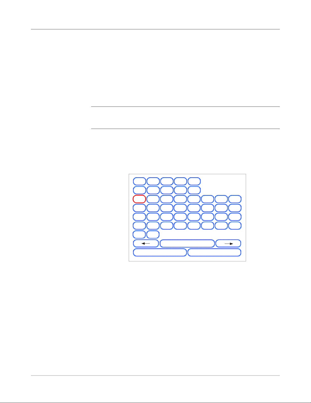
4 • Advanced Operation
Overview
Using the Alphanumeric Matrix
This chapter explains use of the alphanumeric matrix and system use that
exceeds the System Operator level of access. Functions explained in the
chapter are:
• Using the Alphanumeric Matrix
• Saving a Job
• Deleting a Job
• Assigning User IDs and Passwords (Manager Level Only)
• Enabling and Disabling the High Capacity Sheet Feeders (HCSF)
NOTE: Entry of a access code or password from a Supervisor and/or Manager
is required for use of these functions. Refer to Access Rights in Chapter 2 in this
guide for more information about logging in using the two security modes.
The alphanumeric matrix allows you enter text for naming items and job, for
entering job comments, and for logging in and out of the system.
1
6 7
A
I
2
B
J
4
3
8
C
K
9
D E
M
L
5
0
G
F
N
O
H
P
Q
Y Z
Esc
^
Backspace
Alphanumeric Matrix
1. Use the UP/DOWN and LEFT/RIGHT Screen Navigation Arrow keys to
select any of the following:
• Desired character.
• Add a (blank) space in the Job Name and/or Job Comments.
• Backspace to delete the character that appears immediately to the
left of the highlight.
• Left or Right arrow keys within the matrix to navigate within the text.
2. Press OK to display the selected character in the highlighted area of the
screen, move left or right, or to delete the character immediately to the
left of the highlight.
S
.
T U
/
Space
-
V
@
Clear All
R
W
X
"
'
4-2 SV61311 Rev. E
Page 89

Advanced Operation • 4
Saving a Job
Saving a job requires supervisor or manager access rights.
To save a new job:
1. Select “Yes, Save” from the “Create – Save Created Job” screen. Refer
to Creating a Job in Chapter 3 of this guide for more information.
NOTE: If you are not logged in with supervisor or manager access rights, you
will be prompted to enter an access code.
2. The “Save Job” screen displays. Use the alphanumeric matrix to enter
the name of the job. Job names can contain up to 15 characters.
3. Select “Finished” when done.
To save edits and updates made to an existing job:
1. Select "Save Current Job" from the Job Screen. Refer to Editing a Job in
Chapter 3 of this guide for more information.
NOTE: If you are not logged in with supervisor or manager access rights, you
will be prompted to enter an access code.
2. The “Save Job” screen displays. Select “Finished” to save updates, and
edits made to the current job.
To save current job as a different job (new or replace existing job):
1. Select "Save Current Job" from the Job Screen. Refer to Editing a Job in
Chapter 3 of this guide for more information.
NOTE: If you are not logged in with supervisor or manager access rights, you
will be prompted to enter an access code.
2. The “Save Job” screen displays. Use the alphanumeric matrix to edit the
name of the job. Job names can contain up to 15 characters.
3. Select "Finished" when done.
SV61311 Rev. E
4-3
Page 90

4 • Advanced Operation
Deleting a Job
Jobs that display in the Saved Jobs list are the only jobs that can be deleted.
NOTE: Library jobs are permanent residents of the system's memory. The "Delete" function is disabled for the any of the Library jobs.
To delete a job from the Saved Jobs list:
1. From the Home Screen for any job, select "Menu."
2. Select "Jobs."
3. Select "Delete Saved Job." The list of saved jobs displays.
NOTE: If you are not logged in with supervisor or manager access rights, you
will be prompted to enter an access code.
4. Select the name of the job you want to delete.
5. Select "Delete job" to confirm the delete command.
NOTE: Selecting "Delete" causes permanent deletion of this job from the
system's memory. However, if this is the current job the job name will appear
on the Home screen, as it is still in the system's "working" memory. Additionally, a copy of the deleted job can be run if it appears in the Recently Run Jobs
list.
Delete Job
Press to scroll.
Press to move highlight.
A
B
C
D
Job: NVOICE 1
INVOICE 1
INVOICE 2
INVOICE 3
INVOICE 4
INVOICE 5
INVOICE 6
INVOICE 7
Next
Delete Job Screen
4-4 SV61311 Rev. E
Page 91

Advanced Operation • 4
Assigning User IDs and Passwords
You must have Manager level access rights to assign a user ID and password.
1. From the Home screen, select "Menu" and then "Tools."
2. Select "Configure System" and then "Security Level."
NOTE: If you are not logged in with supervisor or manager access rights, you
will be prompted to enter an access code.
3. The Security screen displays. Select "User ID Setup."
4. Select "Add New User."
5. The Enter User Name screen displays:
a. Use the alphanumeric matrix to enter the user ID.
b. Select "Finished" when done.
6. The Select User Level screen displays:
a. Use the UP/DOWN arrow keys to select the appropriate access level
(operator, supervisor, or manager.)
NOTE: Refer to Access Rights in Chapter 2 of this guide for more infor-
mation.
b. Select "Accept User Level" when done.
7. The Enter Password screen displays:
a. Enter the password.
Enabling and Disabling the High Capacity Sheet Feeder (HCSF)
NOTE: Passwords are four-digit numeric codes. Numbers 1, 2, 3, 4 and
5 display on the rst screen. Press "Next" to access numbers 6, 7, 8, 9,
and 0.
b. Select "Finished" when done.
Follow the steps below to enable or disable the HCSF.
1. On the control panel, enable the Upper and/or Lower Feeder Trays.
2. From the Home screen, select "Menu", "Tools", then "Configure System",
and finally "Tools".
3. Select “Enable” or "Disable" for the Feeders that you want.
4. Select "Accept", and then press HOME.
SV61311 Rev. E
4-5
Page 92

4 • Advanced Operation
This page is intentionally blank.
4-6 SV61311 Rev. E
Page 93

5 • Troubleshooting and
Maintenance
Adjusting Screen Brightness and Contrast ..................................5-2
Setting the Time and/or Date .......................................................5-3
Changing the Language ..............................................................5-4
Refilling the Sealing Solution .......................................................5-5
Handling Material Stoppages ......................................................5-5
Clearing a Stoppage .............................................................. 5-5
Resuming the Job .................................................................. 5-6
Handling Outsorted Material .................................................. 5-6
Troubleshooting Tables................................................................5-7
Routine Maintenance.................................................................5-16
Daily Tasks .......................................................................... 5-16
Replacing the Moistener Wick ............................................. 5-16
Replacing the Moistener Brushes ........................................ 5-18
5-1SV61311 Rev. E
Page 94

5 • Troubleshooting
Adjusting Screen Brightness and Contrast
Follow the steps below to adjust the contrast and/or brightness of the dis-
play screen:
1. From the Home screen, select "Menu".
2. From the Menu screen, select "Tools".
3. From the Tools screen, select "Configure System".
4. From the Configure System screen, select "Set Brightness/Contrast".
5. From the Set Brightness/Contrast screen:
• Press the UP/DOWN arrow key(s) to increase/decrease screen
brightness.
• Press the LEFT/RIGHT arrow key(s) to decrease/increase screen
contrast.
• To return to the default settings, select "Restore Defaults".
6. When you are done:
• Press "Finished" to back through the configure system screens and
return to the Home screen. Your settings will be saved.
OR
• Press HOME to save your adjustments and return directly to the
Home screen.
Set Brightness/Contrast
Press to adjust Brightness.
Press to adjust Contrast.
Job: 123
100%
0%
0%
Restore Defaults
Set Brightness/Contrast Screen
5-2 SV61311 Rev. E
100%
Finished
Page 95

Troubleshooting • 5
Setting the Time and/or Date
Follow the steps below to adjust the internal Time and/or Date of the sys-
tem:
1. From the Home screen, select "Menu".
2. From the Menu screen, select "Tools".
3. From the Tools screen, select "Configure System".
4. From the Configure System screen, select "Set Date/Time".
NOTE: If you are not logged in with supervisor or manager access rights, you
will be prompted to enter an access code.
5. Press the LEFT/RIGHT arrow key(s) to select the item you want to
change, i.e., Month, Day, Year, Hour, or Minute. The items highlight as
you press the LEFT/RIGHT arrow key(s).
6. Press the UP/DOWN arrow key(s) to select the desired number.
7. When you are done:
• Press "Finished" to back through the configure system screens to
the Home screen. Your settings will be saved.
OR
• Press HOME to save your adjustments and return directly to the
Home screen.
Set Time/Date
Press to select.
Press to adjust.
SV61311 Rev. E
Month Day Year Hour Minute
7
Set Time/Date Screen
22 2006 23 54
Finished
5-3
Page 96

5 • Troubleshooting
Changing the Language
Follow the steps below to change the language used on the display screen:
1. From the Home screen, select "Menu".
2. From the Menu screen, select "Change Language".
3. The Change Language screen displays the list of available languages. If
necessary, use the "Next" and "Previous" options to view additional languages on the list, then select the appropriate language.
4. Select "Finished" when done.
5. Press HOME to return directly to the Home screen.
Change Language
English International
English
North American
Français
Français Canada
Change Language Screen
Deustch
Español
Italiano
Next
5-4 SV61311 Rev. E
Page 97

Troubleshooting • 5
Refilling the Sealing Solution
A warning message appears on the Display screen indicating that it is time
to replenish sealing solution in the Sealer bottle :
To refill the bottle:
1. Open the Sealer bottle cover and remove the bottle from its holder on
the system and place it on a flat surface.
2. Unscrew the pressure-sensitive top and remove it from the bottle.
3. Pour sealing solution into the bottle until it reaches the fill line.
NOTE: Water is an acceptable liquid to use in the Sealer, but is not recommended. The use of water can result in bacterial growth that can inhibit the
performance of the Sealer.
5. Screw the pressure-sensitive top securely back onto the bottle.
6. Wipe off any excess fluid that may have spilled.
7. Put the bottle back into the holder and close the Sealer cover.
NOTE: First time use of the sealing system, as well as situations in which the
wick has become dry, will require a brief waiting period to allow the wick to get
moist.
Handling Material Stoppages
Clearing a Stoppage
If a stoppage occurs, the system immediately stops the run and displays an
error message. Follow the instructions on the Display screen to get your
system running again.
The procedure(s) involved with removing material that has caused the stoppage, resuming the run, and handling the outsorts are explained next.
The procedure for clearing a stoppage varies and depends on the area in
which the stoppage occurs. In general, the steps to clear a stoppage consist
of the following:
1. Use the error message information on the Display screen to locate the
problem area.
2. If needed, open any covers that allow access to the stoppage. Clear only
the area indicated. If prompted to clear deck, press CLEAR DECK.
Refer to Chapter 2 if you need help on cover removal and/or use of the
Paper Release Knobs for accessing and removing stoppage.
3. Follow the instructions on the Display screen to clear the stoppage.
4. Once the stoppage is cleared, close any open cover(s). The error message will clear and the Home screen will display.
SV61311 Rev. E
5-5
Page 98

5 • Troubleshooting
Resuming the Job
Handling Outsorted Material
To resume running your job after a stoppage is cleared:
1. Make sure that there are no error messages on the screen and that all
system covers are closed.
2. Press START.
• If the error message on the screen instructed you to remove mate-
rial in trays to start a new collation, pressing START will begin a new
collation, otherwise
• The job will resume counting from the last complete mail piece that it
produced.
During the recovery from jams and other machine stoppages, the system
will automatically clear material from the transport deck that cannot be
completed by the inserter.
The system counts all mail pieces that it has successfully completed (trial
pieces included), but partially assembled pieces are not counted and are
transported to the upper divert area. The user has two options The system
handles outsorts in these ways:
• Discard the items.
• Manually assemble the piece.
5-6 SV61311 Rev. E
Page 99

Troubleshooting • 5
Troubleshooting Tables
The system will generate an error message when a problem occurs. The
message identifies the error and possibly the cause of it. Advice on fixing the
problem will also display. In addition to these messages, use the:
• Tables that appear in this manual to identify problems and corrective
action(s).
• Help file, that is accessible through the Control Panel by pressing HELP,
to view information on system functions and procedures.
If you cannot resolve your problem using these self-help aides, call your system supplier.
Table 5-1 Startup Problems
Problem Cause Action
System won’t power up. System power cord is not plugged into
the wall outlet.
No power at outlet. Check outlet. Verify that wall outlet has power.
Faulty Power Supply, circuit board
wiring, or Power Switch.
Plug power cord into wall outlet.
Call your system supplier.
Table 5-2 Control Panel Problems
Problem Cause Action
• No display; but system
power is on. (LED in
upper right corner of the
Control Panel is orange or
green.)
• Display locks up.
• Screen Option Keys don’t
work.
• Machine Keys don’t work.
Display is too light or dark
(contrast and/or readability
problem).
SV61311 Rev. E
Faulty circuit boards or power supply,
loose wiring, or poor connections.
Display timeout. Press the OK key turn on the display.
Poor contast/brightness adjustment. Adjust contrast and/or brightness settings.
Press the power button to restart system. If
problems persist, call your system supplier.
See Adjusting Screen Brightness and
Contrast in this chapter.
5-7
Page 100

5 • Troubleshooting
Table 5-3 Tower Feeder Problems
Problem Cause Action
Failure to feed. Material not within specifications. Check that all material meets published
specifications. Refer to
Feeder Tower Material Specifications in
Chapter 6 of this guide for more information.
• Remove curled or warped material.
• Use only material that has been stored
properly.
NOTE: High humidity can make paper limp
and cause curling. Additionally, recycled
material can sometimes be problematic.
Improper loading. • Be sure to fan (aerate) material before
loading.
• Be sure to follow the loading instructions
as suggested on the display screen.
• Check side guides.
NOTE: Guides set tightly up against
stack can disrupt or prevent material from
feeding.
• Check that material is loaded in the
correct feeder and in the proper
orientation.
Double or multiple feeds;
stream feeding.
Paper fragments or debris in tray,
rollers or tower transport.
Material not within specifications. Check that all material meets published
Improper loading. Be sure to fan (aerate) material before loading,
Dirty, worn or glazed feed and/or
retard rollers.
Inspect feed rollers and transport path.
Remove paper fragments before running a
clear deck.
specifications. Refer to Feeder Tower Material
Specifications in Chapter 6 of this guide for
more information.
NOTE: Some glossy materials contain
contaminates that can clog feed rollers and
cause stream or double feeds.
especially material that has been printed
recently.
NOTE: Low humidity can cause paper to
accumulate a static charge and cling together.
Clean or replace affected rollers. Contact your
system supplier.
5-8 SV61311 Rev. E
 Loading...