

Page 1
DI800 FastPac
Inserting System
™
SV40188-OG Rev. A
OPERATOR GUIDE
Page 2

WARNING
This equipment generates, uses and can radiate radio frequency
energy and if not installed and used in accordance with the
instruction manual, may cause interference to radio communications. It has been tested and found to comply with the limits for
a Class A computing device pursuant to Subpart B of Part 15 of
FCC Rules, which are designed to provide reasonable protection
against such interference when operated in a commercial environment. Operation of this equipment in a residential area is
likely to cause interference, in which case the user, at their own
expense, will be required to take whatever measures are required
to correct this interference.
Trademark Notice
FastPac™ is a trademark of Pitney Bowes, Inc.
First Edition, September 2002
©2002 Pitney Bowes Inc.
All rights reserved. This book may not be reproduced in whole or in part in any
fashion or stored in a retrieval system of any type or transmitted by any means,
electronically or mechanically, without the express written permission of
Pitney Bowes.
We have made every reasonable effort to assure the accuracy and usefulness of
this manual, however we cannot assume responsibility for errors or omissions
or liability for the misuse or misapplication of our products.
Page 3

FastPac™ Inserting System Contents
Chapter 1: Introduction................................... 1-1
In This Book .............................................................. 1-1
Introduction................................................................ 1-2
Safety ......................................................................... 1-7
A Note to the Operator .............................................. 1-8
Material Specifications .............................................. 1-9
Chapter 2: The Base Unit ................................ 2-1
Overview.................................................................... 2-1
Controls and Indicators .............................................. 2-5
Setup and Adjustments ............................................ 2-19
Running Test Material ............................................. 2-38
Tips to Reduce Setup Time ...................................... 2-40
Clearing Material From the Base Unit.................... 2-41
Maintaining the Base Unit ....................................... 2-44
Chapter 3: The Single Feeder Modules ......... 3-1
Overview.................................................................... 3-1
Controls and Indicators .............................................. 3-7
Setup and Adjustments ............................................ 3-17
Running Test Material ............................................. 3-33
Tips to Reduce Setup Time ...................................... 3-34
Clearing Material From the Feeder.......................... 3-35
Maintaining the Feeder ............................................ 3-38
What is OMR? ......................................................... 3-40
Page 4

ii
FastPac™ Inserting System — Contents
Chapter 4: The Folder...................................... 4-1
Overview.................................................................... 4-1
Controls and Indicators ............................................ 4-10
Setup and Adjustments ............................................ 4-16
Running Test Material ............................................. 4-25
Tips to Reduce Setup Time ...................................... 4-28
Clearing Material From the Folder ......................... 4-30
Maintaining the Folder ............................................ 4-32
Document Inverter Operation .................................. 4-33
Chapter 5: The Crossfolder ............................ 5-1
Overview.................................................................... 5-1
Controls and Indicators .............................................. 5-4
Setup and Adjustments ............................................ 5-11
Running Test Material ............................................. 5-32
Tips to Reduce Setup Time ...................................... 5-32
Clearing Material from the Crossfolder................... 5-34
Maintaining the Crossfolder .................................... 5-34
Chapter 6: The Burster Interface.................... 6-1
The Burster Interface ................................................. 6-1
Setup and Adjustments .............................................. 6-4
Chapter 7: Electronic Setup ........................... 7-1
Overview.................................................................... 7-1
Types of Operators ..................................................... 7-2
Page 5

FastPac™ Inserting System — Contents
Control Panel ............................................................. 7-3
Job Numbers .............................................................. 7-4
Startup ........................................................................ 7-5
Operator Functions .................................................... 7-6
Review any of the job settings: ...................... 7-7
Selecting another job to run: ........................ 7-11
Running test material and starting a run: ..... 7-12
Clearing the Deck: ....................................... 7-13
Resetting the Job Count: .............................. 7-14
Resetting the Base Cumulative Count: ........ 7-14
Key Operator, Module Functions ............................. 7-15
Module Options: .......................................... 7-16
Language:..................................................... 7-24
iii
Speed:........................................................... 7-25
Key Operator, OMR Setup ....................................... 7-26
Flowchart for OMR Setup Screens .............. 7-28
OMR Present/Off ......................................... 7-29
OMR Present/EOC Only.............................. 7-31
OMR Present/Multi Line ............................. 7-40
Chapter 8: Troubleshooting ............................ 8-1
Mechanical Problems................................................. 8-1
Messages on the Screen ............................................. 8-6
Page 6

iv
FastPac™ Inserting System — Contents
Appendix A: The Twin Feeder Modules ........ A-1
Overview................................................................... A-1
Controls and Indicators ............................................. A-7
Setup and Adjustments ........................................... A-17
Running Test Material ............................................ A-33
Tips to Reduce Setup Time ..................................... A-34
Clearing Material From the Feeder......................... A-35
Maintaining the Feeder ........................................... A-38
What is OMR? ........................................................ A-40
Is the Module Equipped with OMR? ...................... A-41
Key Operator, Module Functions ............................ A-44
Key Operator, OMR Setup...................................... A-49
Messages on the Screen .......................................... A-50
Index .................................................................. I-1
Page 7

Chapter 1: Introduction
In This Book
This book contains information that explains the FastPac™ Inserting System DI800. There are several chapters in this book.
The chapter you are now reading, Chapter 1, contains:
❑ System Introduction—describes the FastPac™ Inserting
System DI800 and how the system can fill your mailing needs.
❑ Safety—outlines safety practices that you should follow.
❑ A Note to the Operator—a reminder to read this manual
before operating your FastPac™ Inserting System DI800.
❑ Material Specifications—a listing of the kinds of material
appropriate to use in the FastPac™ Inserting System DI800.
Chapters 2 — 4 and Appendix A describe the Base Unit, the
Single Sheet Feeder and Insert Feeder, the Folder, and the Twin Sheet
Feeder and Insert Feeder. Chapters 5 and 6 describe the optional
Crossfolder Module and the Burster Interface. These chapters contain:
❑ An introduction to the module—a discussion of the module
and how it fits in the FastPac™ Inserting System DI800.
❑ Controls and Indicators—illustrates the various parts of the
modules and explains their usage.
❑ Mechanical Setup and Adjustments—step-by-step proce-
dures on how to make the necessary mechanical setup and
adjustments to the modules to get the system up and running.
❑ Running Test Material—how to test settings and adjustments.
❑ Maintaining the Module
Chapter 7 covers the electronic setup for the FastPac™ Inserting
System DI800. This chapter discusses the use of the Main Control
Panel located on the Base Unit. These functions are separated into
two categories: those functions available to all operators and those
available only to a key operator.
Chapter 8 covers troubleshooting for the FastPac™ Inserting
System DI800. Included are error messages, their meaning, and
suggestions for correcting the problem.
Page 8

1-2
Chapter 1: Introduction
Introduction
This manual is about the FastPac™ Inserting System DI800. The
FastPac™ Inserting System DI800 is a modular system, one machine made up of a group of compact, versatile, building blocks.
These building blocks, or “modules” work together to create a
“collation” or “mailpiece.” A collation or mailpiece is simply a
group of papers that go into one envelope to be mailed to one
addressee. That means the FastPac™ Inserting System DI800 must
have modules to feed paper, fold paper, add extra inserts to the
collation, insert that accumulated collation into an envelope, and
seal the envelope.
A FastPac™ Inserting System DI800 can also perform some more
complex tasks, such as “optical mark recognition” (OMR). That
means the system is equipped with a scanner, much like those used
for cash registers in check out lines, to read and process paper with
special dash mark codes.
The modular units of the FastPac™ Inserting System DI800 are
streamlined and compact. They are designed to fit on the top of
most work tables. Which components are included in your FastPac™
Inserting System DI800 depends on your application needs. During installation, your Pitney Bowes representative will fully explain all of the modules. During operator training, you will learn
what each module does and why it was included in your system.
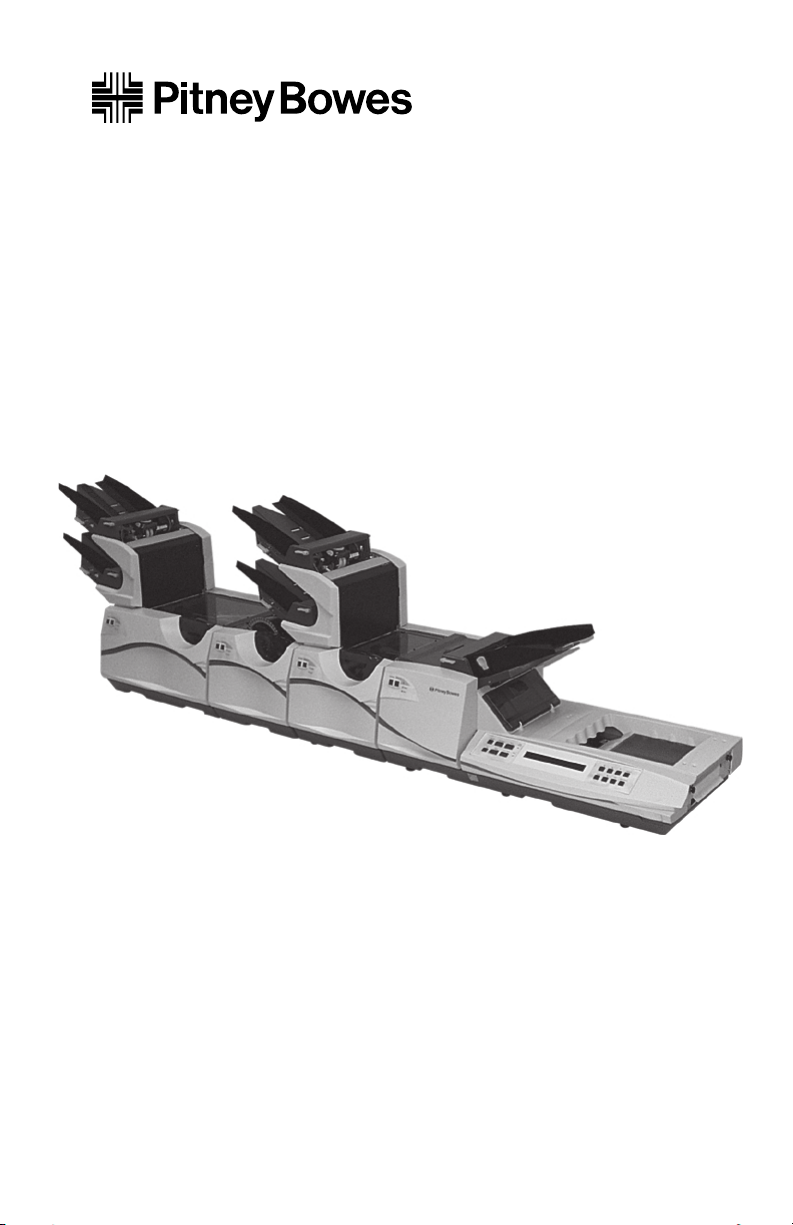
The simplest configuration for a FastPac™ Inserting System
DI800 is a Base Unit and one feeding module, such as an Insert
Feeder. More elaborate configurations are possible to fill a wide
range of needs. The illustration on the next page shows a simple
FastPac™ Inserting System DI800. The modules shown, a Sheet
Feeder, Folder, Insert Feeder, and Base Unit are all explained in
this manual.
Page 9
Chapter 1: Introduction
Introduction
Single Sheet
Feeder (F583)
Single Insert
T
r
i
a
l
P
i
e
c
e
I
n
S
e
r
v
i
c
e
B
y
e
n
t
i
P
R
e
a
d
y
F
a
u
l
t
Feeder (F581)
s
e
w
o
R
e
R
s
e
e
t
v
/
i
e
w
T
r
i
a
l
P
i
e
c
e
J
S
J
t
o
a
b
r
t
P
a
u
A
s
e
d
d
W
a
t
e
r
C
l
e
a
r
D
e
c
k
S
e
a
l
S
e
t
u
p
R
e
p
o
r
t
E
x
i
t
Z
e
r
o
C
o
u
n
t
T
ri
al
P
i
e
c
e
I
n
S
e
r
v
i
c
e
F
a
u
l
t
R
e
a
d
y
I
n
R
S
e
a
e
d
r
y
v
i
c
e
F
a
u
l
t
T
r
i
a
P
l
i
e
c
e
T
ri
al
P
ie
c
e
In
S
e
r
v
i
c
e
s
e
w
o
B
y
e
n
t
i
P
R
e
a
d
y
F
a
u
l
t
T
ria
l
P
i
e
c
e
I
n
S
e
r
v
i
c
e
s
e
w
o
B
y
e
n
t
i
P
R
e
a
d
y
F
a
u
l
t
Folder
(F582)
Base Unit
(F580)
Figure 1-1—A Simple FastPac™ Inserting System DI800
1-3
F500_029
Complete FastPac™ Inserting System DI800s always include the F580
Base Unit. Which modules are included in addition to the Base Unit
depends on your needs. A FastPac™ Inserting System DI800 can consist
of any of the following modules, up to a total of five plus the Base Unit.
❑ Base Unit (F580)—Every FastPac™ Inserting System DI800
must have the Base Unit. Consult Chapter 2 of this manual for
a detailed explanation of the Base Unit. You can't operate the
FastPac™ Inserting System DI800 without thoroughly understanding the Base Unit.
❑ Insert Feeder—The F581 Single Insert Feeder (Chapter 3)
and F587 Twin Insert Feeder (Appendix A) adds an insert to the
collation that is inserted in the envelope by the Base Unit. The
feeder is capable of feeding a wide variety of forms and
materials by moving the paper along with a belt and gate
system. The feeder holds material until the next module is
ready to accept it.
Page 10

1-4
Introduction
❑ Sheet Feeder—The F583 Single Sheet Feeder ( Chapter
3) and F588 Twin Sheet Feeder (Appendix A) can feed a
supply of single sheets or collect a set (up to six sheets)
from another module. The sheet feeder passes a complete
set to the next module (usually a folder).
❑ OMR capability—The F504/F516 OMR is an optional
feature, that can be attached to either the F581 Single Insert
Feeder or the F583 Single Sheet Feeder (Chapter 3). The
OMR option continuously scans enclosures as they leave
a feeder deck. If an End of Collation (EOC) mark is
recognized, it passes the collation to the next downstream
module for processing.
❑ Folder (F582)—The Folder (Chapter 4) is included in a
system to accept paper (from one to six sheets) from
upstream modules, fold it into one of four common folds
(single fold, letter fold, accordion fold, or double fold) and
pass it downstream to the Base Unit. The folder also has a
bypass mechanism to let paper pass through the folder if
you do not want the paper folded.
Chapter 1: Introduction
❑ Cross Folder (F407)—The Cross Folder (Chapter 5)
handles large pieces of paper by single folding a sheet once
and then changing the direction of the paper so that a
second fold module can fold it again.
❑ Different “input devices” such as bursters and cutters can
also be added to the FastPac™ Inserting System DI800.
These attach to the FastPac™ Inserting System DI800 at
the opposite end from the Base Unit, at the furthest
upstream point, to feed special forms into the FastPac™
Inserting System DI800. The F422 Burster Interface is
covered in Chapter 6. The 3324 Burster is covered in
SV40025.
Page 11
Chapter 1: Introduction
Introduction
Components do not have to be in a specific order, but logically,
certain functions must follow other functions (i.e., sheets must be
fed before they can be folded, and they need to be folded before they
can fit in an envelope).
As paper moves through the FastPac™ Inserting System DI800 we
say it is flowing “downstream.” The Base Unit is always located at
the most downstream position, the position all the way to the right
when facing the operator side of the machine (the side with the
control panels). The furthest upstream module, usually a sheet
feeder, is all the way to the left.
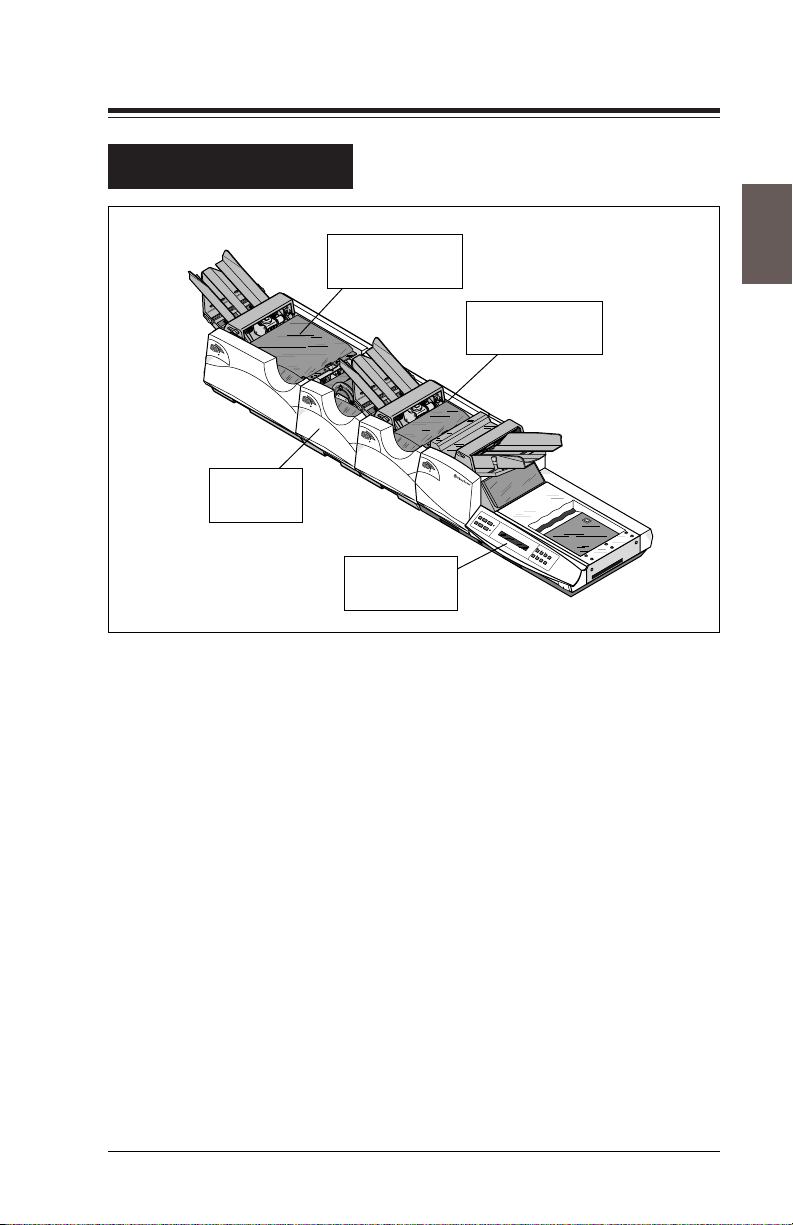
In many of the messages displayed on the main control panel on the
Base Unit, modules are referred to by number. These are the
numbers that the FastPac™ Inserting System DI800 assigns to each
module based on its position in the system. The Base Unit is not
numbered and the most upstream module is always number one.
The numbers increase as you move downstream toward the Base
Unit. See Figure 1-2 below.
1-5
Sheet Feeder
Module
Number 1
Folder
Module
Number 2
Insert
Feeder
Module
Number 3
Base Unit
The Base Unit is
Not Numbered
UPSTREAM DOWNSTREAM
Figure 1-2—Paper flows downstream
Page 12

1-6
Chapter 1: Introduction
Introduction
Additional capabilities include Fold Only, Daily Mail, Continuous/Batching stacking modes, and Double Detect reference methods.
• Fold Only allows you to process material through the FastPac™
Inserting System DI800, but not insert it into an envelope.
• Daily Mail is a feature which allows you to interrupt a job to
process a small job, and then go back to the original job. Note
that new setup may be required for the Daily Mail and then a
return to the original setup.
• Continuous/Batching stacking modes allow you to process one
piece after another (Continuous), a counter counting continuously, or in batches of 25 with a counter counting the batches
from 25 down to zero (Maximum batch count is 250).
• Double Detection can be set up on Start where thickness of the
first piece through is measured and then used as a reference for
subsequent sheets. It can also be set up by using the Trial Piece
method. In Trial Piece, the envelope is not sealed, allowing you
to examine the collation to be sure it is correct.
Page 13

Chapter 1: Introduction
Safety
The Tabletop Inserting System is equipped with safety interlocks
that prevent operation under certain circumstances. Never attempt
to defeat these devices; you’ll endanger yourself and co-workers.
• Keep loose clothing, jewelry, and long hair away from all
moving parts.
• Avoid touching moving parts or materials while machine is in
use. Before clearing a jam, be sure mechanisms come to a stop.
• When removing jammed material, avoid using too much force to
protect against minor personal injury and damaging equipment.
• Use the power cord supplied with the machine and plug it into an
easily accessible, properly grounded wall outlet located near the
machine. Failure to properly ground the machine can result in
severe personal injury and /or fire.
• The power cord is the primary means of disconnecting the
machine from the AC supply.
• DO NOT use an adapter plug on the line cord or wall outlet.
• DO NOT remove the ground pin from the line cord.
• Avoid using wall outlets that are controlled by wall switches or
shared with other equipment.
• DO NOT route the power cord over sharp edges or trap it between
furniture.
• Ensure there is no strain on the power cord where it becomes
jammed between the equipment, walls, or furniture.
• Be sure the area in front of the wall receptacle into which the
machine is plugged is free from obstruction.
• Do not remove covers. Covers enclose hazardous parts that
should only be accessed by Pitney Bowes Customer Service.
Report any damage of covers to your Pitney Bowes Customer
Service representative.
• To prevent overheating, do not cover the vent openings.
• Read all instructions before attempting to operate the equipment.
• Use this equipment only for its intended purpose.
1-7
In addition, follow any specific occupational safety and health
standards for your workplace or area.
Page 14

1-8
Chapter 1: Introduction
A Note to the Operator
The instructions in this guide explain how to set up and use the
modules in a basic FastPac™ Inserting System DI800. Being
familiar with the information in this manual helps you keep
problems to a minimum and achieve the best possible performance
from your system.
Before setting up and using the system, you should be completely
familiar with the modules used in your application. Read each
chapter of this manual as your system may include any of the
available modules. This operating guide is meant to help you use
the equipment to its full potential. For additional assistance, contact
your Pitney Bowes Customer Service Representative.
Note that some of the instructions that follow tell you to use the
scales provided on the FastPac™ Inserting System DI800 to take
measurements. Always use these scales as instructed.
Page 15

Chapter 1: Introduction
Material Specifications
These material specifications apply to the FastPac™ Inserting
System DI800.
Envelopes for the F580 Base Unit:
• Envelopes must be flat, straight, and not glued together.
• Envelopes can be standard side seam, diagonal side seam,
executive, die cut, and closed window. The FastPac™
Inserting System DI800 does not run open window envelopes.
• Envelopes must be made from at least 16 lb. bond and no more
than 24 lb. bond material.
• Maximum acceptable envelope size is 6-7/16" (163mm) deep
by 10-3/8" (263mm) wide.
• Minimum acceptable envelope size is 3-1/2" (89mm) deep by
6-3/8" (162mm) wide.
1-9
• Flaps must be between 1-1/4" (32mm) and 2-1/4" (57mm) and
all envelopes must always have at least 1/4" (7mm) clearance
on each side, and a 1/4" (7mm) clearance between the crease
line of the flap and the edge of the insert.
Material for other system modules:
• Sheets for the F583 and F588 Sheet Feeder must be at least
5-1/2" (140mm) wide and no more than 9-7/8" (250mm) wide.
• Sheets for the F583 and F588 Sheet Feeder must be at least 4"
(102mm) deep, but no more than 14" (355mm) deep.
• Sheets must be made from at least 16 lb. bond and no more than
24 lb. bond material.
Page 16

1-10
Chapter 1: Introduction
Material Specifications
• The thickness of the full collation feeding through the sheet
feeder must not exceed .072" (2.0mm). If sheets are to be
folded, thickness must not exceed .024" (0.6mm) or 6 sheets.
• Inserts for the F581 and F587 Insert Feeder must be at least
5-1/2" (140mm) wide and no more than 9-7/8" (250mm) wide.
• Inserts for the F581 and F587 Insert Feeder must be at least 21/2" (64mm) deep, but no more than 6" (152mm) deep.
• Insert thickness must not exceed .100" (2.5mm).
• The depth of all material must be within 1/2" (12mm) of each
other in the accumulator section of the Insert Feeder.
• The depth of all inserts must be within 1/2" (12mm) of the depth
of a folded sheet.
• The folder is limited to six sheets of 20 lb. bond, or if the fold
desired is a Double Fold, then only 3 sheets may be folded.
• If input includes a crossfolded document, only a single sheet
may be added before the fold is made.
• Material to be fed and read by an OMR kit installed on an F583
and F588 Sheet Feeder is a single sheet of material within the
specification of the F583 and F588 Sheet Feeder.
• If the OMR is installed on an F581 and F587 Insert Feeder,
depth and width of material is the same as specified for F581
and F587.
• The thickness of the material when scanning cannot exceed
.020" (0.5mm). The thickness when not scanning can reach
.100" (2.5mm).
Page 17

Chapter 2: The Base Unit
Overview
The F580 Base Unit is the primary and required component of the
FastPac™ Inserting System DI800. The primary functions of the
Base Unit are to insert the collation into an envelope, process that
envelope, and control the system from commands entered at the
Main Control Panel.
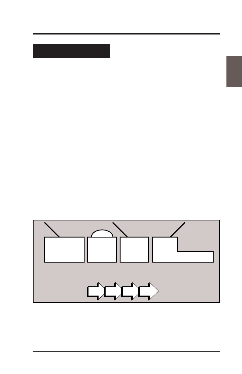
The Base Unit consists of several main sections; see Figure 2-1,
next page:
• the envelope feeder
• the flapper
• the insert station
• the turner/ejection station
• the sealer
• the Main Control Panel
Other modules in the system are always located to the left (or
“upstream”) of the Base Unit. Paper flows from these modules
toward the Base Unit—often referred to as flowing “downstream”—
flowing toward the Base Unit.
!
WARNING: As we've stated, the Base Unit is just one
component of the entire FastPac™ Inserting System
DI800. Each module was “docked” to the other
modules in the system by your service representative
when it was installed.
Never attempt to separate the modules. This is for
service personnel only.
Page 18
2-2
Overview
Incoming
Collation Path
T
r
i
a
l
P
ie
c
e
I
n
S
e
r
v
i
c
e
R
e
a
d
y
F
a
u
l
t
Chapter 2: The Base Unit
Flapper Area
Envelope
Feeder
Bridge
Turner
Sealer
Reset/
Review
Trial Piece
JJob
Start
Pause
Add
Water
Clear Deck
Seal
Insert Station
Main Control Panel
Figure 2-1—The Base Unit (F580)
Setup
Report
Exit
Zero Count
Eject Station
F500_043
Page 19

Chapter 2: The Base Unit
Overview
The following describes how paper moves through the Base Unit.
• The envelope feeder holds a supply of envelopes and feeds
them to the flapper area of the Base Unit. Like the feeder
modules described later, the envelope feeder has a separating mechanism that separates individual envelopes from
the stack loaded in the feeder. The separating mechanism
peels them away, one at a time, from the stack and feeds
them down to the paper path.
• The flapper section of the Base Unit opens the flap on the
envelope. As the envelope feeds into the flapper, the lead
edge of the envelope, opposite the flap edge, enters a pair
of rollers. The bottom roller rotates, wrapping the envelope
around until the downstream edge of the envelope contacts
the flap openers. As the envelope continues to move, the
flap openers pull the flap away from the body of the
envelope. Once the flap is pulled open, the envelope enters
the insert station where a sensor detects its arrival. Another
sensor detects if the flap is open.
2-3
• In the insert station the envelope throat is opened to receive
the collation being fed from upstream modules. Three
throat openers (two located on either side of the envelope
and one in the center), are rotated into the throat of the
envelope, pulling the envelope open to receive a collation.
When the body of the envelope is open to receive the
collation, a signal is sent that the envelope is ready, and the
collation is fed from the upstream module into the open
envelope.
continued-->
Page 20

2-4
Overview
Chapter 2: The Base Unit
• A sensor verifies that the collation is inserted, causing the
Base Unit to pass the filled envelope to the turner section
where it is rotated 90˚. As the mailpiece exits the insert
station, the turner stops are raised to stop the mailpiece in
the turner area. When the leading edge of the mailpiece hits
the stops at the downstream end of the turner, the envelope
stops and is turned 90° to be properly aligned for the sealer.
• Defective pieces are ejected by an eject mechanism. This
provides a way to sort out unstuffed envelopes or incomplete collations. Ejection is done just after the insert
station, preventing the mailpiece from being turned, sealed,
and counted.
• The turned envelope feeds into the sealer where the flap is
guided back toward a partially closed position and then
passed over a moistener where moisture is applied to the
glue on the flap. The envelope then passes through a pair
of rollers that apply pressure to the wet, gummed surface
of the envelope flap, sealing the envelope. When you select
the no-seal option, the diverter prevents the flap from
passing over the moistener.
A drawer pulls out of the front of the Base Unit for adding
water to the sealer. A mechanical float is located in the
reservoir to indicate the water level and help avoid over
filling. A light on the Main Control Panel warns when the
water level is low.
• The Base Unit also houses the Main Control Panel with the
operator interface for all the modules in the system; these
are the buttons you use to perform electronic setup on the
entire FastPac™ Inserting System DI800.
• The On/Off power switch is also located on the front of the
Base Unit. This controls power for the entire system.
Page 21

Chapter 2: The Base Unit
Controls and Indicators
Controls and indicators on the Base Unit are described next. Each
illustration is labeled with numbers pointing out specific items in
the picture. An explanation of how the numbered control works or
what the indicator shows you is provided below the illustration.
Review these descriptions before you go on to the setup instructions that follow. Understanding where everything on the equipment is located will help you keep your FastPac™ Inserting System
DI800 running smoothly and help you set the machine properly to
get the most from it.
This section of the chapter is intended to show you where things are,
not necessarily how to use them. Study the illustrations to see where
things are located and use the section on Setup and Adjustments to
learn how to operate the controls.
2-5
Page 22

2-6
Controls and Indicators
T
r
i
a
l
P
i
e
c
e
I
n
S
e
r
v
i
c
e
R
e
a
d
y
F
a
u
lt
R
e
R
s
e
e
t
v
/
i
e
w
T
r
ia
l
P
i
e
c
e
J
S
J
t
o
a
b
r
t
P
a
u
A
s
e
d
d
W
a
t
e
r
C
le
a
r
D
e
c
3
1
k
S
e
a
l
2
Chapter 2: The Base Unit
S
e
t
u
p
R
e
p
o
r
t
E
x
i
t
Z
e
r
o
C
o
u
n
t
F500_043
Figure 2-2—Major Controls
1. Power Switch—A rocker switch that controls power to the
Base Unit and the entire FastPac™ Inserting System DI800.
2. Main Control Panel—The Main Control Panel has fourteen
push buttons on the keypad, two status lights, and a display
screen. Use the keys to perform setup for the Base Unit and the
entire FastPac™ Inserting System DI800. If the LED on a key
is lit, that function is available; if the LED is dark, that function
is not currently available.
3. Mini Control Panel—A small control panel ( located on each
of the FastPac™ Inserting System DI800 modules) which
indicates if the module is on or off, ready, or has a fault. Use this
control panel to run a single trial piece through a specific
module.
Page 23
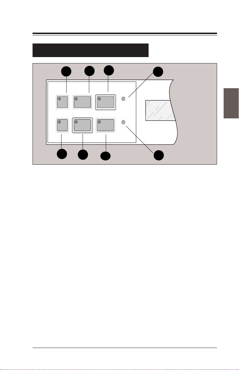
Chapter 2: The Base Unit
Controls and Indicators
2-7
1
Review Trial Piece Start
5
Figure 2-3—Main Control Panel, Left Side of Display
2
Stop Clear DeckJob
6
3
Add
Water
Seal
7
4
8
1. Review—Press for module-by-module review of the system
settings for the selected job.
2. Trial Piece—Press to assemble one complete inserted mail-
piece for inspection. The mailpiece will be ejected.
3. Start—Press to start continuous processing.
4. Add Water Light—Lights when the sealer requires more
water or sealing solution.
F400_096
5. Job—Press to change the selected job. Press as many times as
needed to display the desired job number. Up to ten different
jobs (groups of electronic setup commands) can be stored.
6. Stop—Press to halt the system.
7. Clear Deck—Always press before turning off the machine to
end a run or a job. The machine will cycle until all pieces on the
transport deck have been fully assembled, inserted and stacked.
Only pieces needed to complete collations will feed so that the
deck is clean when the machine stops.
8. Seal Light—Lights when the seal option is activated.
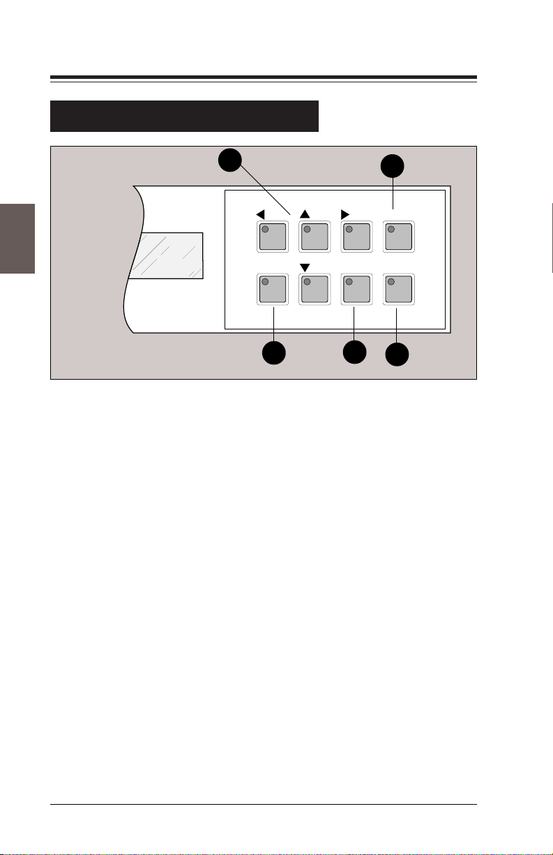
Page 24
2-8
Controls and Indicators
Chapter 2: The Base Unit
1
Setup Exit Zero Count
3
Figure 2-4—Main Control Panel, Right Side of Display
2
Report
4
5
1. Arrow Keys—Use as indicated on the display to move from
one choice to another or to make a selection.
2. Report—Press to display the current reading of the cumulative
counter. The cumulative counter keeps track of the number of
valid collations (pieces of mail) processed by the system. The
count is independent and not affected by the Zero Count key
(see below). You can use the cumulative counter as a general
purpose counter to track the daily piece count, an operator
piece count, or as a backup to the job counter.
3. Setup—After the job number you want is displayed on the
screen, press this key to enter the setup mode, then use the
arrow keys. A code is required to access the job setup functions.
4. Exit—Press to exit the setup mode.
5. Zero Count—Press to reset the piece counter to zero, e.g., at
the beginning of a new job or run.
Page 25
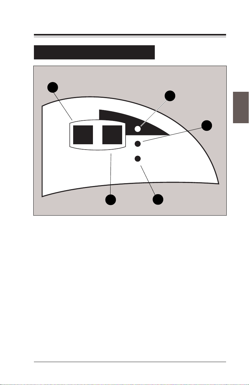
Chapter 2: The Base Unit
Controls and Indicators
5
Trial Piece In Service
2-9
3
2
Ready
Fault
4
F500_030
Figure 2-5—Mini Control Panel
1
1. Fault Light—Lights to indicate a fault has occurred at this
module.
2. Ready Light—Lights to indicate the module is ready for
operation.
3. In Service Light—Lights to indicate if the module is in
service, that is on, for the job being run.
4. In Service Control—Press this key to take the module in and
out of service (i.e., turns the feeder function on and off). The
unit is in service when the light (Item 3 above) is illuminated.
Turn the module off when using Fold Only mode (documents
not inserted into envelope, but material will still pass through).
5. Trial Piece—Press this key to cycle the module once.
Page 26
2-10
Controls and Indicators
Chapter 2: The Base Unit
4
5
T
r
ia
l P
ie
c
e
I
n
S
e
r
v
i
c
e
R
e
a
d
y
F
a
u
l
t
3
R
e
R
s
e
e
t
v
/
i
e
w
T
r
i
a
l
P
i
e
c
e
J
S
J
t
o
a
b
r
t
P
a
u
A
s
e
d
d
W
a
t
e
r
C
l
e
a
r
D
e
c
k
S
e
a
l
F500_043
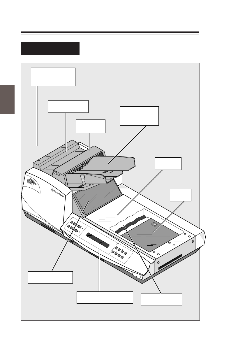
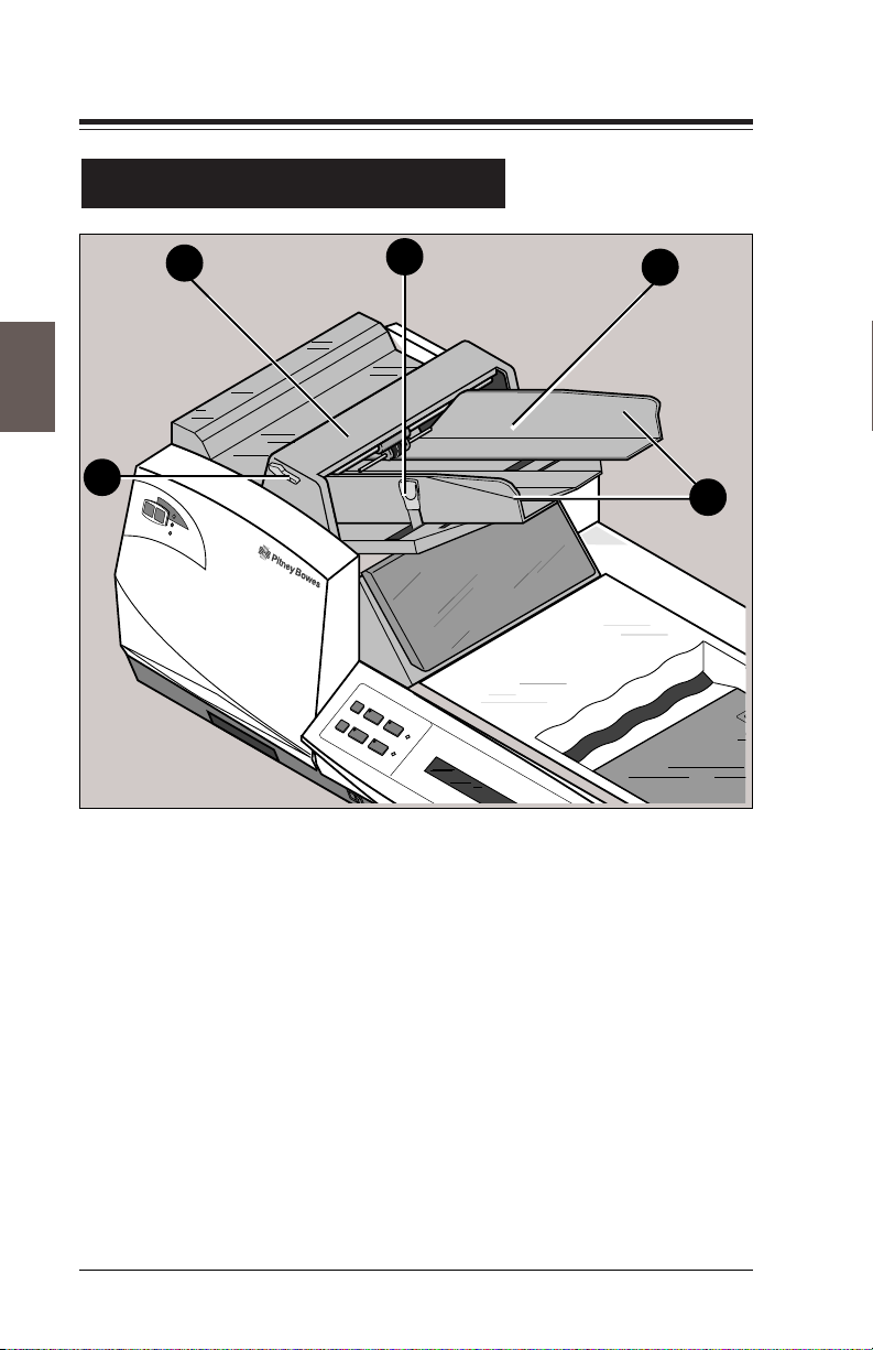
Figure 2-6—Envelope Feeder
1. Envelope Feeder—Holds supply of envelopes.
1
2
2. Feeder Guides—Adjust these guides to hold the envelopes in
place as they feed down to the deck.
3. Feeder Guides Lock Lever—Blue lever pushes in to release
side guides so they can be adjusted.
4. Envelope Feeder Bridge—The piece that covers the separa-
tor gap. The main feed roller is located below this bridge.
5. Roller Release Lever—This is used to access paper under the
Main feed roller.
Page 27
Chapter 2: The Base Unit
Controls and Indicators
3
T
r
i
a
l
P
i
e
c
e
I
n
S
e
r
v
i
c
e
R
e
a
d
y
F
a
u
l
t
R
e
R
s
e
e
t
v
/
i
e
w
T
r
i
a
l
P
i
e
c
e
J
S
J
t
o
a
b
r
t
P
a
u
A
s
e
d
d
W
a
t
e
r
C
l
e
a
r
D
e
c
k
S
e
a
l
2-11
S
e
t
u
p
R
e
p
o
r
t
E
x
i
t
Z
e
r
o
C
o
u
n
t
1
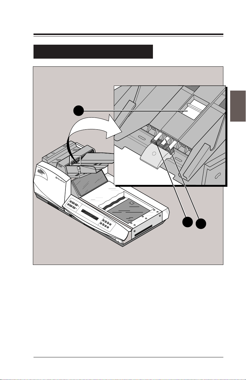
Figure 2-7—Stone and Shield
1. Envelope Feeder Stone—Works with the Main Feed Roller
to create the necessary friction for peeling one envelope at a
time away from the stack in the envelope feeder.
2. Envelope Feeder Stone Shield—Adjust to reveal more or
less of the stone.
3. Envelope Feeder Stone Shield Adjuster—Slide back and
forth to adjust the amount of shield which affects how much
friction is used to feed envelopes.
2
F500_048
Page 28
2-12
Controls and Indicators
1
T
r
i
a
l
P
i
e
c
e
I
n
S
e
r
v
i
c
e
R
e
a
d
y
F
a
u
l
t
R
e
R
s
e
e
t
v
/
i
e
w
T
r
i
a
l
P
i
e
c
e
J
S
J
t
o
a
b
r
t
P
a
u
A
s
e
d
d
W
a
t
e
r
C
l
e
a
r
D
e
c
k
S
e
a
l
Chapter 2: The Base Unit
S
e
t
u
p
R
e
p
o
r
t
E
x
i
t
Z
e
r
o
C
o
u
n
t
2
F550_010
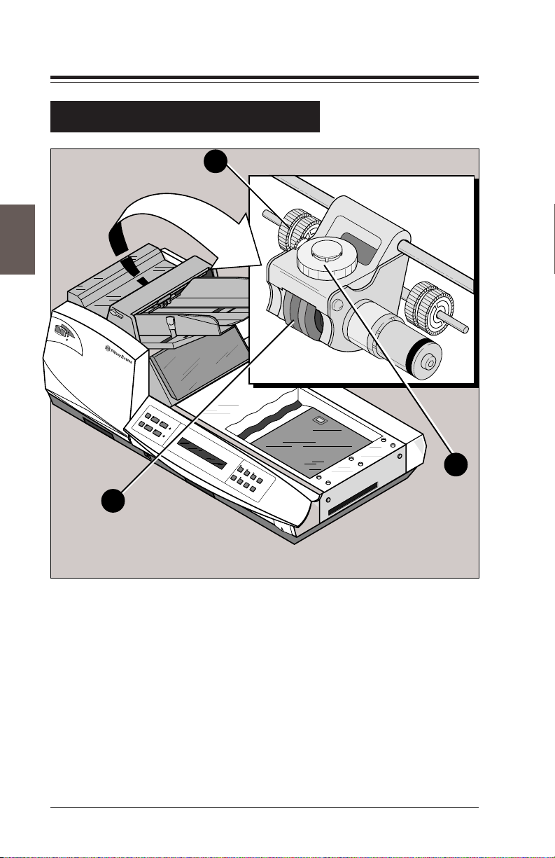
Figure 2-8—Separating Mechanism
1. Envelope Feeder Prefeed Rollers—Help move one envelope
to the separating stone and main feed roller.
2. Envelope Feeder Main Feed Rollers—Move envelopes one
at a time down from the feeder to the flapper.
3. Separator Gap Adjustment Wheel—Raises and lowers the
main feed rollers to adjust the “separating gap.” To adjust for
better separation, turn the adjustment wheel clockwise to raise
the rollers and counterclockwise to lower them.
3
Page 29
Chapter 2: The Base Unit
Controls and Indicators
3
1
2-13
4
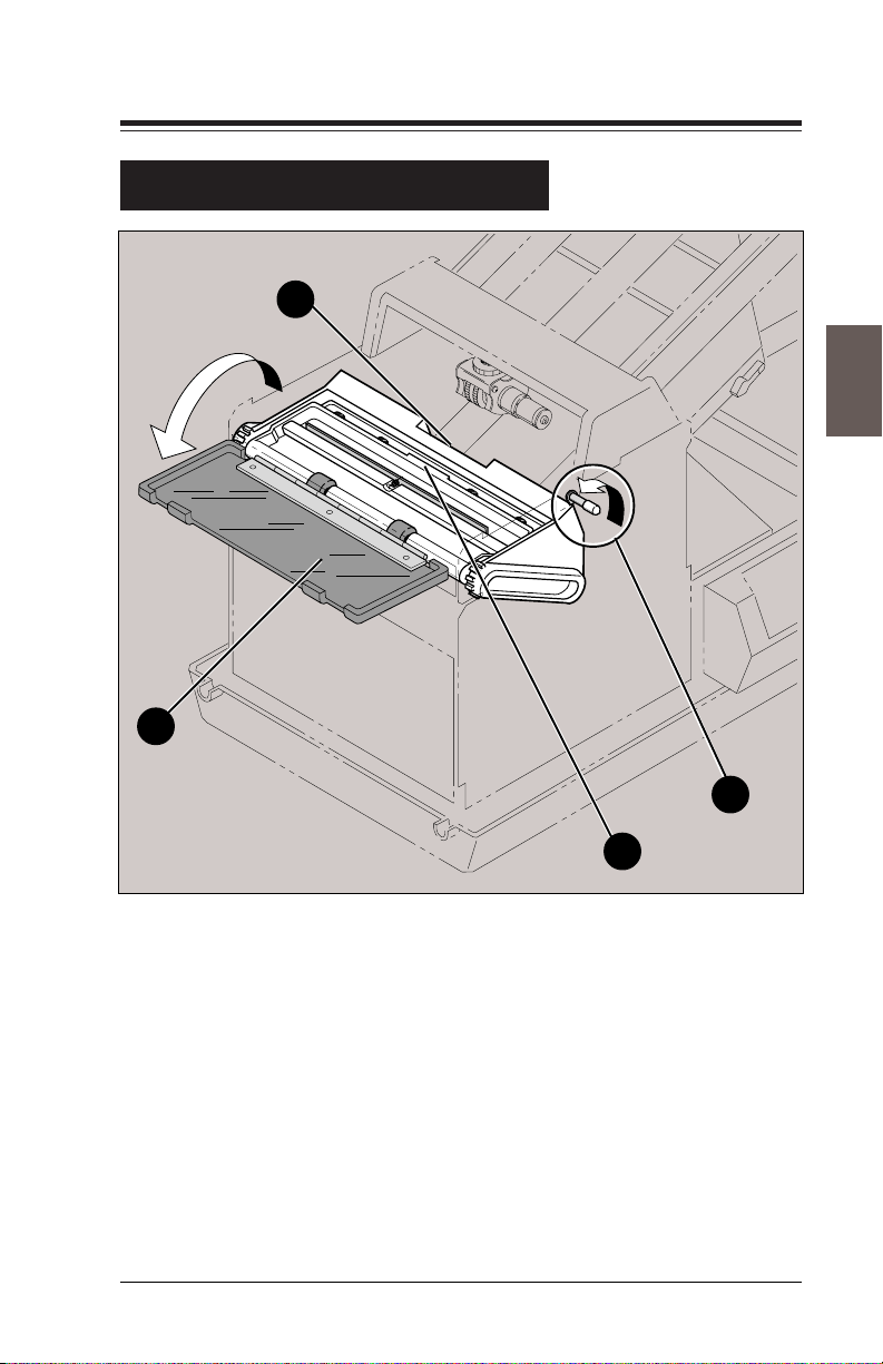
Figure 2-9—Envelope Flapper Unit
1. Envelope Flapper Unit Safety Cover—Flip open to access
envelope flapper unit to remove envelope misfeeds.
2. Envelope Flapper Cover Lock Lever—Pull this lever to
release flapper unit. Flapper unit gently pivots when unlocked.
3. Recessed Area on Flapper Unit—Pull here after flapper unit
is unlocked to expose more of the flapper unit.
4. Tab on Flapper Unit—Pull here to gain access to the inside of
the flapper.
2
Page 30

2-14
a
Controls and Indicators
10
1
2
0
1
2
3
4
190
180
170
100
0
2
1
90
0
3
1
0
4
1
1
6
0
150
Chapter 2: The Base Unit
1
3
R
e
v
ie
w
T
r
i
Figure 2-10—Insert Station Envelope Side Guides
1. Envelope Side Guides—Guides in the insert area that hold the
envelope in place after it’s opened. The two guides keep the
envelope lined up with the oncoming mailpiece for insertion
(only one guide is visible here).
2. Envelope Side Guides Setting Knob—Small blue knob lo-
cated on the side frame of the module, under the cover. Turn the
knob to move the scale until the pointer indicates the measured
width of the envelope.
3. Scale and Pointer—Match the pointer to the measured width
of the envelope on the scale.
F400_133
Page 31

Chapter 2: The Base Unit
Controls and Indicators
1
T
r
i
a
l
P
i
e
c
e
I
n
S
e
r
v
i
c
e
R
e
a
d
y
F
a
u
l
t
0
1
1
1
0
0
0
2
1
9
0
0
3
1
0
1
2
3
140
1
4
6
0
150
210
200
190
180
170
160
R
e
R
s
e
e
t
v
/
i
e
w
T
r
ia
l
P
ie
c
e
J
J
o
0
10
01
0
2
0
3
0
4
0
1
5
0
2
6
0
3
7
0
4
8
0
9
0
1
0
0
1
1
0
1
2
0
1
3
0
1
4
0
1
5
0
1
6
0
1
7
0
1
8
0
1
9
0
2
0
0
2
1
0
2
2
0
2
3
0
b
P
a
u
s
e
C
le
a
r
D
2-15
110
100
120
0
1
2
3
4
S
t
a
r
t
A
d
d
W
a
te
r
e
c
k
S
e
a
l
S
e
tu
p
9
0
0
3
1
140
160
150
R
e
p
o
r
t
E
x
it
Z
e
ro
C
o
u
n
t
0
1
0
0
1
2
2
3
7
0
4
F500_045
Figure 2-11—Throat Opener Adjustment
1. Throat Opener Adjustment Knob—Turn to set stops in the
insert area. This moves the gear at the base of the knob, moving
the black scale until the pointer indicates the correct measurement. Pull this knob out and turn it to set the small pointer on
the inside to the number on the knob rim that coincides with the
number measured on the throat opening scale.
2. Throat Opening Scale—Align edge and corner of the enve-
lope crease with this scale. Where the throat meets the vertical
line on the scale, read number to be set on throat opener
adjustment knob.
Page 32

2-16
Controls and Indicators
Chapter 2: The Base Unit
3
0
1
1
100
0
2
1
9
0
30
1
0
1
2
0
4
1
3
160
4
0
5
1
1
9
0
1
8
0
1
7
0
110
100
120
0
1
2
3
4
90
0
3
1
140
160
150
1
2
Figure 2-12—Turner Stop Adjustment
9
0
1
0
0
1
1
0
1
2
0
1
3
0
1
4
0
1
5
0
1
6
0
F500_060
1. Turner Stop—Set when you set the throat opener adjustment.
2. Turner Stop Adjustment Knob—The same as the Throat
Opener Adjustment Knob. Turn to set the pointer to the
measured depth of the envelope. This moves the gear at the
base of the knob which moves the black scale until the pointer
indicates the correct measurement. Note that turning this knob
also sets the stops in the insert area.
3. Turner Stop Pointer—Shows adjustment of the Turner Stop.
This black scale moves when you turn the knob.
Page 33

Chapter 2: The Base Unit
Controls and Indicators
1
2-17
3
2
Figure 2-13—Envelope Guide
1. Envelope Guide—Keeps the envelope straight as it comes out
of the turner, so that it travels into the sealer aligned properly.
2. Envelope Guide Adjustment Knob—Turn to unlock the
envelope guide and use to push the guide into place along the
scale. Move the pointer to the number on the scale that matches
the measured depth of the envelope and lock in place.
3. Envelope Guide Pointer and Scale—Shows the adjustment
of the envelope guide; should match the depth of the envelope.
F500_044
Page 34

2-18
Controls and Indicators
Chapter 2: The Base Unit
1
2
5
Figure 2-14—The Sealer Section
4
1. Sealer Cover—Squeeze latch to release cover, lift to access
the sealer below.
3
2. Sealer Ramp—Lower the ramp to seal envelopes, or to raise
the ramp when you don't want to seal the envelope.
3. Sealer Adjuster—Moves the sealer ramp to Seal or No Seal.
4. Sealer Moisteners—Apply moisture to flap of the envelope.
3
5. Sealer Refill Tray—Pull out to add water or sealing solution
when the control panel indicates that the water level is low,
being careful not to overfill.
Page 35

Chapter 2: The Base Unit
Setup and Adjustments
There is no required specific order to the mechanical setup of the
Base Unit. These instructions, however, follow the same order that
the paper flows through the Base Unit. Be sure to follow these
instructions when you are first learning how to set up the system so
that you make sure you learn all of the steps.
The following pages describe how to perform the mechanical setup
of the Base Unit in nine steps. These steps are:
1. Set the envelope feeder guides to best hold the envelopes
you'll be using.
2. Adjust the stone and shield to get the best separation.
3. Set the separator gap—the space between the main feed roller
and the stone—and the prefeed rollers to best accommodate
the material you're feeding.
4. Set the envelope side guides in the insert area.
2-19
5. Adjust the throat openers.
6. Set the envelope guide.
7. Select the seal or no seal option by positioning the sealer ramp
up for no seal and down for seal. Check the water level of the
sealer and fill if needed. Change moisteners periodically.
8. Load the envelope feeder with a supply of envelopes.
To perform the setup, use the detailed explanations that follow.
IMPORTANT: The values the pointers and indicators are
set to when you follow these instructions are to be
!
considered only as a starting point for setup. Due to
variations in material and environment, fine-tuning of
the adjustments may be necessary.
Page 36

2-20
Chapter 2: The Base Unit
Setup and Adjustments
To set up the Base Unit you take several measurements and make
your settings based on those measurements. Every envelope put
through the Base Unit has several important dimensions:
• Width
• Length
• Thickness
• Throat Opening
Be sure you know which dimension the instructions are telling you
to work with and measure carefully on the scales inside the Base
Unit front cover.
Throat Opening
(about 1/2” from
side of envelope)
○○○○○○
Depth
○○○○○○○○○○
Thickness
T
r
i
a
l
P
i
e
c
e
I
n
S
e
r
v
i
c
e
R
e
a
d
y
F
a
u
l
t
0
1
1
1
0
0
0
2
1
9
0
0
3
1
0
1
2
0
4
3
1
1
4
6
0
0
5
1
2
1
2
0
0
1
0
9
0
1
8
1
0
7
0
1
6
0
01
0
01
0
2
0
3
0
4
0
1
5
0
2
6
0
3
7
0
4
8
0
9
0
1
0
0
1
1
0
1
2
0
1
3
0
1
4
0
1
5
0
1
6
0
1
7
0
1
8
0
1
9
0
2
0
0
2
1
0
R
e
R
s
e
e
t/
v
ie
w
T
r
ia
l
P
ie
c
e
J
S
J
ta
o
b
r
tA
P
a
u
s
e
d
d
W
a
te
r
C
le
a
r
D
e
c
k
S
e
a
l
2
2
0
2
3
0
S
e
tu
p
R
e
p
o
r
t
E
x
it
Z
e
r
o
C
o
u
n
t
F500_059
Figure 2-15—Envelope Dimensions
Width
Use scale inside Base
Unit front cover to take
measurements.
Page 37

Chapter 2: The Base Unit
Setup and Adjustments
1. Set the Envelope Feeder Guides (see Figure 2-16)
A. Grasp the side guides while pushing the blue lever on the
side inward (toward the guide). Move the side guides in or
out to adjust for envelope size. Release the blue lever when
the side guides are at the proper width for the envelope (i.e.,
they have minimal clearance to the envelope pack).
B. Check the envelope width compared to the position of the
prefeed rollers. Move the outer prefeed roller along the
shaft to match the envelope width. If you moved the feeder
guides in for a small envelope, push the prefeed roller in
also.
2-21
Adjust feeder guides and
prefeed rollers to the width
of the envelope.
Prefeed
Rollers
Figure 2-16—Envelope Feeder Guide Adjustment
Side Guide
Adjustment
Lever
F550_004
Page 38

2-22
Chapter 2: The Base Unit
Setup and Adjustments
2. Adjust the stone and shield to get the best separation (see
Figure 2-17).
A. Prefeed rollers help grab a single envelope from the loaded
stack and feed it to the separating mechanism. You control
the position of the rollers above the deck by physically
moving them with your hand and locking them at the
desired position with a knurled knob that is located under
the bridge. The rollers can either be located up, off the
paper, or down, in contact with the paper.
Lift the roller shaft to move the prefeed rollers to the raised
position. While holding the rollers in the raised position,
use your other hand to turn the knurled knob under the
bridge until you feel it catch, locking the rollers into the
raised position.
B. The shield covers the stone and is located just under the
bridge. Use the sliding control in the bottom of the feeder
to expose or cover the stone with more or less shield. Slide
the shield away from the bridge to expose more stone,
toward the bridge to cover the stone.
C. Start with about 1/8" to 1/4" of the stone exposed. Push and
pull an envelope between the main feed roller and the stone
by hand; if it moves too easily, move the shield to expose
just a bit more stone. If an envelope can't move between the
main feed roller and stone at all, cover the stone with a bit
more of the shield. Exposing less stone will help move
envelopes; exposing more stone can help prevent doubles.
If envelopes “prefeed” too far (slide too far into the
separator gap) try exposing more stone.
Page 39

Chapter 2: The Base Unit
Setup and Adjustments
Move the prefeed
rollers to the raised
position, and lock
them in place by
turning the knurled
knob until it catches.
T
r
i
a
l
P
i
e
c
e
In
S
e
rv
ic
e
R
e
a
d
y
F
a
u
lt
2-23
Adjuster
R
e
R
s
e
e
t
v
/
i
e
w
T
r
i
a
l
P
i
e
c
e
J
S
J
t
o
a
b
r
t
P
a
u
A
s
e
d
d
W
a
t
e
r
C
le
a
r
D
e
c
k
S
e
a
l
S
e
t
u
p
R
e
p
o
r
t
E
x
i
t
Z
e
r
o
C
o
u
n
t
Shield
Stone
Figure 2-17—Setting the Separator Stone Shield
F500_040
Page 40

2-24
Chapter 2: The Base Unit
Setup and Adjustments
3. Set the separator gap—the space between the main feed
roller and the stone—and the prefeed rollers to best accommodate the material you're feeding (see Figure 2-18):
A. The separator gap is the space between the main feed
rollers and the stone. Set the separator gap to best accommodate the material you're feeding by using the thumbwheel
located on top of the feeder bridge.
B. Always make this adjustment with the prefeed rollers in the
up position. Open the gap by turning the thumbwheel
clockwise. This raises the rollers slightly. Now hold an
envelope in your right hand and slide it under the rollers
from the right of the bridge (just as it would feed). Turn the
wheel counterclockwise with your left hand to lower the
rollers closer to the envelope while at the same time
moving the paper back and forth under the main feed
rollers.
C. Use the thumbwheel to open or close the gap until the
resistance is correct. The resistance is about right when the
envelope turns the main feed rollers slightly as you pull it
back and forth under the roller. Turn the thumbwheel a bit
beyond the point when you first begin to feel a drag on the
envelope.
D. Set the prefeed rollers correctly for the type of material
you're running. Lower them for heavier material, such as
envelopes. Raise the rollers for lighter material, such as
single sheets, thin inserts, or light cards (see Figure 2-17).
Page 41

Chapter 2: The Base Unit
Setup and Adjustments
T
r
i
a
l
P
i
e
c
e
I
n
S
e
r
v
i
c
e
R
e
a
d
y
F
a
u
l
t
R
e
R
s
e
e
t
v
/
i
e
w
T
r
i
a
l
P
i
e
c
Be sure roller
release lever is in
the down position
before setting gap.
e
J
S
J
t
o
a
b
r
t
P
a
u
A
s
e
d
d
W
a
t
e
r
C
l
e
a
r
D
e
c
k
S
e
a
l
2-25
Use the horizontal
thumbwheel to adjust
the separator gap—the
space between the main
feed roller and the stone.
S
e
t
u
p
R
e
p
o
r
t
E
x
i
t
Z
e
r
o
C
o
u
n
t
Horizontal
Thumbwheel
Shield
Envelope
Stone
Figure 2-18—Setting the Separator Gap
F550_013
Page 42

2-26
Chapter 2: The Base Unit
Setup and Adjustments
4. Set the Envelope Side Guides in the Insert Area (see Figure
2-19):
A. Using the scale inside the Base Unit front cover, measure
the width of the envelope.
B. Using the envelope side guide setting knob, the small knob
projecting from the left side of the scale, as shown, turn
until the pointer indicates the width you just measured.
C. Turning this knob moves the side guide in the insert area,
as shown in the illustration.
D. For the Fold Only feature, repeat Steps A-C above, but
substitute a pre-folded document instead of an envelope.
Page 43

Chapter 2: The Base Unit
Setup and Adjustments
These guides move
when the setting
knob is adjusted.
T
r
i
a
l
P
i
e
c
e
I
n
S
e
r
v
i
c
e
R
e
a
d
y
F
a
u
l
0
1
0
01
020304050607
t
1
8
1
7
0
1
6
0
1
2
3
08090100 1
4
1
0
1
2
0
1
3
0
1
4
0
1
5
0
1
6
0
1
7
0
1
8
0
1
9
0
2
0
0
2
102
2
0
1
1
1
0
0
0
2
1
90
0
3
1
0
1
2
0
3
14
1
4
6
0
150
2
1
2
0
0
1
0
9
0
0
R
e
R
s
R
e
e
t
e
v
/
R
s
i
e
e
e
w
t
v
/
i
e
w
T
r
i
a
T
l
P
r
i
a
i
e
l
c
P
e
i
e
c
e
J
S
J
t
o
b
J
S
J
t
o
a
b
r
P
a
u
P
s
e
a
u
s
e
C
l
e
a
C
r
l
e
D
a
e
r
c
D
k
e
c
k
S
S
e
0
2
3
0
2-27
a
r
t
t
A
d
d
W
A
a
d
t
d
W
e
r
a
t
e
r
e
a
l
a
l
S
e
t
u
S
p
e
t
u
p
R
e
p
R
o
e
r
t
p
o
r
t
E
x
i
t
E
x
i
t
Z
e
r
o
Z
e
C
r
o
o
u
C
n
o
t
u
n
t
Adjusting this
control moves the
160
guides inside the
150
insert area.
Figure 2-19—Insert Area Side Guide Adjustment
170
180
190
200
210
F500_036
Page 44

2-28
Chapter 2: The Base Unit
Setup and Adjustments
5. Set the Envelope Throat Opener (see Figure 2-20):
A. Begin by measuring the envelope throat. Open the flap of
an envelope, and fold the flap over completely behind the
envelope, giving it a strong crease and flattening it.
Place the envelope on the throat opening scale—the tab
located on the scale inside the cover of the Base Unit,
behind the sealer area (see the illustration on the following
page). For correct measurement, be sure the crease of the
folded back flap and the left edge of the envelope are
touching the scale.
With the top and left edge aligned properly, read the
number on the throat scale that corresponds to your
envelope's throat, about 1/2” from the edge of the envelope.
B. Pull the small throat opener adjustment knob out as far as
it will pull away from the body of the Base Unit. With the
knob pulled out, turn it until the pointer on the inside of the
knob indicates the number you measured for the throat of
the envelope on the rim of the knob.
Page 45

Chapter 2: The Base Unit
Setup and Adjustments
Pull this knob out, away from the
body of the module, then turn to align
the pointer with the number you read
from the scale, as shown above.
T
ri
a
l P
ie
c
e
I
n
S
e
r
v
i
c
e
R
e
a
d
y
F
a
u
l
t
180
170
160
0
1
0
010
2
0
3
0
40 5
1
0
2
6
0
3
7
0
4
8
090
1
0
0
1
1
0
1
2
0
1
3
0
1
4
0
1
5
0
1
6
0
17
0
18
0
1
90
2
0
0
2
1
0
22
110
10
0
120
9
0
0
3
1
0
1
2
0
4
3
1
1
4
6
0
0
5
1
210
200
190
R
e
R
s
e
e
t
v
/
ie
w
T
ria
l
P
ie
c
e
J
S
J
ta
o
b
r
tA
P
a
u
s
e
d
d
W
a
t
e
r
C
le
a
r
D
e
c
k
S
e
a
l
0
2
3
0
2-29
110
100
120
0
1
2
3
4
130
S
e
t
u
p
9
0
0
4
1
160
150
R
e
p
o
rt
E
x
it
Z
e
r
o
C
o
u
n
t
0
1
0
0
1
2
3
70
4
Place envelope on tab and read
number corresponding to the throat
opening, about 1/2” from the edge
of the envelope, “1” in this case.
F500_045
Figure 2-20—Setting the Throat Openers
Page 46

2-30
Chapter 2: The Base Unit
Setup and Adjustments
6. Set the Envelope Guide (see Figure 2-22):
A. Set the envelope guide to the same value you measured for
the depth of the envelope.
B. Loosen the envelope guide knob by turning it counterclock-
wise.
C. Slide the knob so that the pointer lines up with the measured
depth.
D. When the pointer indicates the depth, tighten the knob
again by turning it clockwise. The knob should stay in place
to keep the envelope aligned properly as it moves into the
sealer.
E. For the Fold Only feature, repeat Steps A-D above, but
substitute a pre-folded document instead of an envelope.
Page 47

Chapter 2: The Base Unit
Setup and Adjustments
Turn the knob to unlock
the guide and slide it
into place.
2-31
Figure 2-22—Setting the Envelope Guide
F500_044
Page 48

2-32
Chapter 2: The Base Unit
Setup and Adjustments
7. Select Seal or No Seal, Fill and Maintain the Sealer:
A. Unlatch and open the sealer cover. Use the sliding adjust-
ment to set the sealer ramp down for the seal option or the
ramp up for no seal.
Slide this adjustment into the
seal or no seal position.
Figure 2-23—Selecting Seal or No Seal
B. Fill the sealer tray whenever the “add water” light on the
Main Control Panel is illuminated, indicating that the
water level is low.
NOTE: Pitney Bowes E-Z Seal™ sealing solution is recommended
but not required. E-Z Seal™ helps prevent mineral and bacterial
build up in the reservoir.
F500_050
Page 49

Chapter 2: The Base Unit
Setup and Adjustments
Do this by pulling out the tray and adding water until the
float registers full and the control panel indicates the level
is sufficient. You can add water at any time, even when the
machine is running.
T
r
ia
l
P
i
e
c
e
I
n
S
e
r
v
i
c
e
R
e
a
d
y
F
a
u
l
t
R
e
R
1
2
1
1
s
e
e
t
v
/
ie
F
w
T
r
ia
l
P
i
e
c
e
J
S
J
t
o
a
b
r
t
P
a
u
s
e
C
le
a
r
D
e
c
k
S
e
a
l
2-33
A
d
d
W
a
te
r
Float to indicate
water level.
Figure 2-24—Filling the Sealer
CAUTION: Do not overfill the machine or water will
not stay contained in the tray. Pay careful attention
!
to the water level as indicated by the float when
filling the tray. Watch the float, not the indicator
light, while adding water to the machine.
S
e
t
u
p
R
e
p
o
r
t
E
x
it
Z
e
r
o
C
o
u
n
t
F500_046
Page 50

2-34
Setup and Adjustments
C. Maintain the sealer by periodically (approximately four
times a year) changing the moisteners in the sealer unit.
• Open the sealer unit.
• Slide the soiled moistener out and insert a new one. See
Figure 2-25.
• Pry the cover off of the lower moistener, pull out the
cube of moistener material, and replace with a fresh
moistener.
OTE: The upper moistener develops a “fringe” as it is
N
used. This is completely normal and does not interfere with
the moistening process at all. The fringe, however, may be
trimmed occasionally.
Chapter 2: The Base Unit
Page 51

Chapter 2: The Base Unit
Setup and Adjustments
1
5
1
6
0
2-35
Pull the upper moistener out and slide a new
one into its place.
9
0
1
0
0
1
1
0
1
2
0
1
3
0
1
4
0
0
Push the edge of the small
cover over the lower
moistener to gain access
to the moistener below.
F500_052
Figure 2-25—Changing the Sealer Moistener
Page 52

2-36
Chapter 2: The Base Unit
Setup and Adjustments
8. Loading the Envelope Feeder (see Figures 2-26 and 2-27):
A. Before filling the envelope feeder, take a handful of
envelopes and aerate them by holding one end of the stack
and fanning the other. Then hold the other end of the stack
and fan the opposite end.
B. Be sure the envelope flaps are not glued shut or together.
Hold one end of the stack and give the whole stack a shake
in an up and down motion to break any glue spots.
C. Load the envelopes flap-up and bottom-leading. Fan the
stack out away from the feeding rollers.
Aerate
Figure 2-26—Aerate and Flex the material
Flex
Page 53

Chapter 2: The Base Unit
Setup and Adjustments
Envelopes loaded flap-up and
bottom-leading. Fan the stack out
behind the top envelope. The top
envelope feeds first.
2-37
Figure 2-27—Loading the Feeder
F550_005
Page 54

2-38
Chapter 2: The Base Unit
Running Test Material
Once you've made the proper adjustments detailed in steps one to
nine on the previous pages, test the accuracy of the base unit
mechanical settings by running a few pieces of test material through
the module.
There are two ways to run test material through the base unit:
1. To ensure that envelopes are feeding properly, perform
steps one to nine, setting and loading the Base Unit, and
press
Trial Piece on the Mini Control Panel. This feeds one
envelope, turns it, seals it and stacks it. This checks that
envelopes are separating and feeding properly (see Figure
2-28).
2. To ensure that collations are getting inserted properly,
perform mechanical setup on the other modules in the
system, or at least on the one module immediately upstream of the base unit. Press Trial Piece on the Main
Control Panel located on the base unit. This causes the
system to build one test collation, feeding the collation
downstream to the base unit where an envelope will be fed
and opened. The collation will be inserted and the envelope
ejected. This helps you see if the collations are building
properly and being inserted correctly because you can
inspect what's in the envelope.
Page 55

Chapter 2: The Base Unit
rial Piece
ault
Read
In Ser
vice
Running Test Material
T
r
ia
l P
ie
c
e
I
n
S
e
r
v
i
c
e
R
e
a
d
y
F
a
u
l
t
R
e
R
s
e
e
t
v
/
i
e
w
T
r
i
a
l
P
i
e
c
e
J
S
J
t
o
a
b
r
t
P
a
u
A
s
e
d
d
W
a
t
e
r
C
l
e
a
r
D
e
c
k
S
e
a
l
Review Trial Piece Start
Add
Water
2-39
Trial Piece
In Ser
vice
Read
y
Fault
S
e
t
u
p
R
e
p
o
r
t
E
x
i
t
Z
e
r
o
C
o
u
n
t
Stop Clear DeckJob
Seal
F500_034
Figure 2-28—Trial Piece on both the Mini and Main Control Panels
Page 56

2-40
Chapter 2: The Base Unit
Tips to Reduce Setup Time
Note the settings you make to the base unit under a specific job
number on a Job Card located in the Instruction Cards found in the
front of each machine. This helps you remember proper settings for
specific jobs performed repeatedly, saving setup time in the future.
An illustration of a Job Card is shown below. The left side of the
illustration shows how to fill out a job card to show the settings you
made. The right side is still blank.
1
Job #
Job Name
Envelope
1
Throat
Opener
240
Side
Guides
Example Job
No. 10 Window
Prefeed
Rollers
Up
✓
Down
(Check Stone
Shield &
Separator Gap)
240
Feeder
Guides
104
Envelope
Guide
Seal
No Seal
✓
Job #
Job Name
Envelope
Throat
Opener
Side
Guides
Prefeed
Rollers
Up
Down
(Check Stone
Shield &
Separator Gap)
Feeder
Guides
Envelope
Guide
Seal
No Seal
Check
Water
Figure 2-29—An Example of a Job Card
Check
Water
Page 57

Chapter 2: The Base Unit
Clearing Material From the Base Unit
When clearing jammed material, make sure you are moving/
pulling/removing material in the direction it is supposed to flow
through the machine. If you go against the natural feeding direction
of the machine, you could dislodge and/or damage feeding components not designed for this stress.
Use the roller release lever on the side of the
bridge to raise the main feed rollers to help
clear material out from under them. Remember
to close this release lever again.
Use your other
hand to hold the
material in the
feeder back.
2-41
Bowes
Pitney
e
c
i
v
r
e
S
n
I
y
e
d
c
a
e
e
i
R
P
l
a
i
r
T
t
l
u
a
F
F550_0411
Pull out jammed
material in the
Ready
Trial Piece In Service
Fault
direction of the
normal paper flow
Figure 2-30–Raising the Main Feed Rollers to Remove Jams
PitneyBowes
F550_012
Page 58

2-42
Chapter 2: The Base Unit
Clearing Material From the Base Unit
Flip open the flapper unit safety cover to
access the envelope flapper unit to
remove envelope misfeeds. Pull the lock
lever to release flapper unit. Flapper unit
gently pivots upward when unlocked.
Lock Lever
Safety Cover
Tab
With the safety cover opened and the lock
lever released, the flapper unit pivots up.
Pull on the recessed area to expose more of
the flapper unit. Then pull on the tab to gain
access to the inside of the flapper.
Figure 2-31—Clearing the Flapper Unit
Recessed Area
F500_051
Page 59

Chapter 2: The Base Unit
ck
Clearing Material From the Base Unit
Lift the turner here to
reach under it for an
envelope.
T
r
i
a
l
P
i
e
c
e
I
n
S
e
r
v
i
c
e
R
e
a
d
y
F
a
u
l
t
R
e
R
s
e
e
t
v
/
i
e
w
T
r
i
a
l
P
i
e
c
e
J
S
J
t
o
a
b
r
t
P
a
u
A
s
e
d
d
W
a
t
e
r
C
l
e
a
r
D
e
c
k
S
e
a
l
9
0
1
0
0
1
1
0
1
2
0
1
3
0
1
4
0
1
5
0
1
6
0
S
e
t
u
p
R
e
p
o
r
t
E
x
i
t
Z
e
r
o
C
o
u
n
t
2-43
Use the latches in the
insert area and sealer
T
r
i
a
l
P
i
e
c
e
In Service
Ready
Fault
210
200
190
180
170
160
0
1
1
1
0
0
0
2
1
90
130
0
1
2
0
4
3
1
4
160
0
5
1
Reset/
Review
Trial Piece
JJob
Start
Pause
Add
Water
Clear De
area to raise the
covers and access
the transport below.
Use the manual advance
knob to move jammed
material through the
base unit.
F500_037
Figure 2-32—Clearing jammed material from under covers
F500_049
Page 60

2-44
Chapter 2: The Base Unit
Maintaining the Base Unit
To keep the Base Unit running smoothly:
• Remove all paper fragments from the Base Unit, especially
around the separating mechanism.
• Wipe the machine clean at the end of every day with a clean dry
cloth. There is a black stripe below the sensor in the accumulator area. Clean this stripe occasionally by wiping off the
surface of the stripe with a clean dry cloth, as shown in the
illustration. This is to keep the machine free of paper dust and
prevent buildup that could hinder performance.
• Clean all five optical sensors daily, locations shown in Figure
2-33 below.
Clean stripe occasionally
by wiping off the surface
with a clean dry cloth.
110
1
0
0
0
12
90
130
0
1
2
0
4
1
3
160
4
150
190
180
170
F400_054
Flapper
Entrance
Sensor
Collation
Input
Sensor
F400_050
F500_070
Figure 2-33—Maintaining the Sensor
Flapper Exit
Sensor
Insert Station
Sensor
Turner
Entrance
Sensor
Page 61

Chapter 3: The Single Feeder Modules
Overview
NOTE: If you are using a Twin Sheet Feeder (F588) or
Twin Insert Feeder (F587) refer to Appendix A.
This chapter of the manual is about the F583 Single Sheet Feeder
and the F581 Insert Feeder (see Figure 3-1).
The F583 Sheet Feeder is often the first, or most “upstream,”
component in a FastPac™ Inserting System DI800. The F581
Insert Feeder is usually placed after the Folder, and before the Base
Unit, as illustrated below in a typical example of a simple system.
The F581 Single Insert
Feeder is often placed
downstream of the Folder
module, before the Base
Unit.
T
r
i
a
l
P
i
e
c
e
I
n
S
e
r
v
i
c
e
F
a
u
l
t
R
e
a
d
y
I
n
R
S
e
a
e
d
r
y
v
i
c
e
F
a
u
lt
T
r
i
a
P
l
i
e
c
e
T
r
i
a
l
P
i
e
c
e
In
S
e
r
v
i
c
e
Bowes
Pitney
R
e
a
d
y
F
a
u
lt
T
r
i
a
l
P
i
e
c
e
I
n
S
e
r
v
i
c
e
Bowes
Pitney
R
e
a
d
y
F
a
u
l
t
T
r
i
a
l
P
i
e
c
e
I
n
S
e
r
v
i
c
e
Bowes
Pitney
R
e
a
d
y
F
a
u
l
t
R
e
R
s
e
e
t
v
/
i
e
w
T
r
i
a
l
P
i
e
c
e
J
S
J
t
o
a
b
r
The F583 Single Sheet
Feeder is often the most
upstream module and
t
P
a
u
A
s
e
d
d
W
a
t
e
r
C
l
e
a
r
D
e
c
k
S
e
a
l
S
e
t
u
p
R
e
p
o
r
t
E
x
i
t
Z
e
r
o
C
o
u
n
t
placed just before a folder.
F500_029
Figure 3-1—A typical configuration of a FastPac™ Inserting System
DI800
Page 62

3-2
P
i
t
n
e
y
B
o
w
e
s
I
n
S
e
r
v
i
c
e
R
e
a
d
y
F
a
u
l
t
T
r
i
a
l
P
i
e
c
e
T
r
i
a
l
P
i
e
c
e
In
S
e
r
v
ic
e
R
e
a
d
y
F
a
u
lt
P
i
t
n
e
y
B
o
w
e
s
T
r
i
a
l
P
i
e
c
e
I
n
S
e
r
v
i
c
e
R
e
a
d
y
F
a
u
lt
P
i
t
n
e
y
B
o
w
e
s
T
r
i
a
l
P
i
e
c
e
In
S
e
r
v
i
c
e
R
e
a
d
y
F
a
u
lt
R
e
s
e
t
/
R
e
v
i
e
w
T
r
i
a
l
P
i
e
c
e
S
t
a
r
t
A
d
d
W
a
t
e
r
J
J
o
b
P
a
u
s
e
C
l
e
a
r
D
e
c
k
S
e
a
l
S
e
t
u
p
E
x
i
t
R
e
p
o
r
t
Z
e
r
o
C
o
u
n
t
T
r
i
a
l
P
i
e
c
e
I
n
Se
rv
i
ce
R
e
ad
y
F
au
l
t
Chapter 3: The Single Feeder Modules
Overview
The Sheet Feeder and Insert Feeder are almost identical and have
the same controls and adjustments, the only difference being a
longer accumulator section in the Sheet Feeder to accommodate
unfolded or longer material. The accumulator sections of the two
feeders are shown in Figure 3-2 below.
F583 Single
F500_029
Sheet Feeder
Accumulator
Section
F581 Single
Insert Feeder
T
r
i
a
l
P
i
e
c
e
I
n
S
e
r
v
i
c
e
R
e
a
d
y
F
a
u
l
t
T
r
i
a
l
P
i
e
c
e
I
n
S
e
r
v
i
c
Bowes
Pitney
Figure 3-2—The Sheet Feeder and Insert Feeder Vary Only In Size
F513_001
e
R
e
a
d
y
F
a
u
l
t
F501_002
Bowes
Pitney
Page 63

Chapter 3: The Single Feeder Modules
Overview
While some of the following illustrations may show an insert
feeder, assume the facts are the same for the longer sheet feeder,
unless we say specifically that there is a difference.
These instructions explain how to set up and use the feeder modules
in your FastPac™ Inserting System DI800. Your understanding of
what the feeders do and how they work will minimize your
problems and help you get the best possible performance from your
FastPac™ Inserting System DI800.
3-3
Page 64

3-4
Chapter 3: The Single Feeder Modules
Overview
The following is a list of features that describe the feeders:
• The main components of the Insert Feeder (F581) and the
Sheet Feeder (F583) consist of a feeder, a separating
mechanism, and a transport/accumulator section (see Figure 3-3).
• Both feeders have a double detection sensor. This sensor
automatically measures the thickness of one sheet of paper
when it passes under the sensor for the first time. The feeder
stores the measurement for this single sheet in memory. If
subsequent material fed doesn't match this stored value for
the thickness, then the double detector assumes there has
been a double feed—two sheets stuck together. Depending
on choices made in Electronic Setup, Chapter 7, doubles
can be handled in one of three ways: ignored, ejected, or by
the machine stopping.
• Feeders can feed material to the top of a collation brought
in from an upstream module. They can also feed to the
bottom of a collation by feeding to the transport deck before
bringing in the collation from an upstream module.
• Feeders are equipped with sensors that detect successful
feeding of material, and the arrival and exit of the material
in the accumulator section.
Page 65

Chapter 3: The Single Feeder Modules
Overview
3-5
Direction sheets
or inserts feed
01
0203040506070809010
Feeder section
Separator section
60
70
80
90
100
110
120
130 140
140
160
180
200
220
240
0
11
0
1
2
0
1
3
0
1
4
0
15
0
1
6
0
1
7
0
18
0
1
9
0
2
0
0
21
0
2
2
0
2
3
0
150
s
e
w
o
B
y
e
n
t
i
P
Transport/Accumulator
section
Figure 3-3—The Main Sections of a Sheet or Insert Feeder
F551_026
Page 66

3-6
Chapter 3: The Single Feeder Modules
Overview
The following describes the paper flow through the sheet or insert
feeder and what happens in each of the main sections.
• A stack of sheets or inserts is loaded into the feeder section of
the insert or sheet feeder module. The feeder section has selfcentering feeder guides that can be adjusted to any size material
within specifications. Each feeder guide is mechanically linked
to the other so that when you adjust the guides they automatically center themselves (adjust together to keep the center of the
material in the center of the machine). These feeder guides hold
the loaded material straight and in line so that the separating
mechanism can pull one piece at a time from the stack.
• The separating mechanism pulls one insert or sheet from the
stack in the feeder section and feeds it to the transport section.
The separating mechanism consists of a stone, shield, main feed
rollers, and prefeed rollers. The separating mechanism works
because there is friction between the rollers, stone, and paper.
The small set of rollers “prefeed” or push the top piece from the
stack toward the main feed rollers. The main feed rollers move
slightly faster than the prefeed rollers, grabbing one sheet at a
time. Friction between the stack of paper and the stone causes
only the top sheet to advance to the main feed roller while the
rest of the stack is held back. The top sheet or insert is pulled
away from the stack one at a time.
Friction between the paper and stone is adjusted by moving the
shield to expose more or less stone. See Setup and Adjustments
later in this chapter for details on setting the separating mechanism and how it works.
• As each piece of material feeds and separates, the transport
moves it along to the accumulator section. In the accumulator,
paper stops to wait for another insert or sheet to be fed or until
the next downstream module is ready.
• When collation is complete, the accumulator stops rise, allowing the collation to move downstream toward the Base Unit.
Page 67

Chapter 3: The Single Feeder Modules
Controls and Indicators
Controls and indicators on the F583 Sheet and F581 Insert Feeder
modules are described next. Each illustration uses identifying
numbers to point out specific items in the picture. An explanation
of how the control works or what the indicator shows you is
provided below the illustration.
Review these descriptions before you go on to the setup instructions. Understanding where everything on the equipment is located
helps you keep your FastPac™ Inserting System DI800 running
smoothly.
3-7
Page 68

3-8
Chapter 3: The Single Feeder Modules
Controls and Indicators
T
r
ia
l
P
i
e
c
e
I
n
S
e
r
v
i
c
e
R
e
a
d
y
F
a
u
l
t
3
2
s
e
w
o
B
y
e
tn
i
P
1
Figure 3-4—Major Components
1. Cover—The front (operator side) cover drops to provide
access to the Operator Instruction Cards, the paper path, and
setup adjustments.
2. Mini Control Panel—A small control panel, located on each
of the FastPac™ Inserting System DI800 modules, indicates if
the module is in service, ready, or has a fault. Use this control
panel to initiate a run of a single trial piece through a specific
module, or to turn the module's feeder section on and off.
3. Safety Covers—Covers over the belts and rollers to protect
you from moving parts.
F501_002
Page 69

Chapter 3: The Single Feeder Modules
Controls and Indicators
5
3-9
3
T
r
i
a
l
P
i
e
c
e
I
n
S
e
r
v
i
c
e
R
e
a
d
y
F
a
u
l
t
Trial Piece In Service
Ready
Fault
s
e
w
o
B
y
e
n
it
P
1
4
Figure 3-5—Mini Control Panel
1. Fault Light—Indicates if a fault has occurred at this module.
2. Ready Light—Indicates if module is ready for operation.
3. In Service Light—Indicates if this module's feeder section is
in service (on) for the current job.
4. In Service Control—Press this key to turn the feeder section
on and off (e.g., "off" is used to allow material to pass-through
this module without new material being added by this feeder).
2
F501_003
5. Trial Piece—Press to run one piece through this module.
Page 70

3-10
Chapter 3: The Single Feeder Modules
Controls and Indicators
1
2
3
6
07
0
8
0
9
01
0
0
1
1
0
1
2
0
1
3
0
1
4
0
1
5
1
4
0
1
6
0
1
8
0
2
0
0
2
2
0
2
4
0
0
5
s
e
w
o
B
y
e
n
t
i
P
Figure 3-6—Major Components of a Feeder
1. Feeder section—The ramp that holds loaded sheets or inserts
to be fed one at a time down to the transport deck to join the
collation.
2. Separating Mechanism—Peels one sheet or insert at a time
from the stack in the feeder.
3. Bridge—Mounted over the separating mechanism.
4. Accumulator—The section of the feeder where the collation
waits to receive another piece of material before continuing to
the next module in the FastPac™ Inserting System DI800.
5. Manual Advance Knob—Turn to move paper through the
feeder module up to the accumulator stops.
4
F551_015
Page 71

Chapter 3: The Single Feeder Modules
Controls and Indicators
1
3-11
2
Figure 3-7—The Separating Mechanism
1. Sheet/Insert Feeder Stone Shield Adjuster—Slide back
and forth to adjust the amount of shield you use which
affects how much friction is used to feed sheets or inserts.
2. Sheet/Insert Feeder Stone—Works with the Main Feed
Roller to create the necessary friction for peeling one sheet
or insert at a time away from the stack in the feeder.
3. Sheet/Insert Feeder Stone Shield—Adjust to reveal more
or less of the stone.
3
F551_009
Page 72

3-12
Chapter 3: The Single Feeder Modules
Controls and Indicators
1
3
2
Figure 3-8—More of the Separating Mechanism
1. Prefeed Rollers—Help move one sheet or insert to the separat-
ing stone and main feed roller.
2. Main Feed Rollers—Move inserts one at a time down from the
feeder to the transport area.
3. Separator Gap Adjustment Wheel—Raises and lowers the
main feed rollers to adjust the “separating gap.” Turn the
adjustment wheel clockwise to raise the rollers and counterclockwise to lower them.
F551_018
Page 73

Chapter 3: The Single Feeder Modules
Controls and Indicators
1
2
3
3-13
T
r
i
a
l
P
i
e
c
e
I
n
S
e
r
v
i
c
e
R
e
a
d
y
F
a
u
l
t
s
e
w
o
B
y
e
n
t
i
P
4
Figure 3-9—The Feeder
1. Feeder Guides—Adjust these guides to hold the sheets or
inserts straight as they feed down to the transport deck.
2. Locking Knobs for Side Guides (under feeder)—Untighten
knobs to adjust side guides, tighten knobs when guides are in place.
3. Feeder Guides Lever—Locks the adjustment of the feeder
guides in place. Turn toward the bridge to unlock, away from
the bridge to lock.
4. Rollers Release Lever—Lift this lever to raise the main feed
rollers, allowing you to access paper under the rollers.
F551_010
Page 74

3-14
Chapter 3: The Single Feeder Modules
Controls and Indicators
F551_016
Figure 3-10—Double Detect Sensor
1. Double Detect Sensor—Detects the incorrect feeding of two
sheets or inserts together. Set when a Trial Piece is sent
through the module or when the first sheet of a job goes
through the detector.
1
Page 75

Chapter 3: The Single Feeder Modules
o
Controls and Indicators
1
60
70
80
90
140
16
0
18
0
2
00
2
20
2
40
3-15
3
100
110
120
130
140
150
F551_015
Figure 3-11—Transport/Accumulator Section
1. Side Guides—Keep the collation straight in the accumulator
section.
2. Transport Belts—Move the collation through the module.
3. Transport Rollers—Move with the transport belts to help
move the collation along. Assist the belts in moving the collation into the downstream module.
2
PitneyB
Page 76

3-16
Chapter 3: The Single Feeder Modules
Controls and Indicators
1
6
0
7
0
8
0
9
0
1
0
0
1
1
0
1
2
0
1
3
0
1
4
0
1
5
1
4
0
1
6
0
1
8
0
2
0
0
2
2
0
2
4
0
0
6
0
7
0
140
160
180
200
220
240
2
8
0
9
0
1
0
0
1
1
0
1
2
0
1
3
0
1
4
0
1
5
0
3
F551_011
Figure 3-12—Accumulator Adjustment
1. Accumulator Stops—Stop the collation to wait for more
material being brought in from the upstream module. Set to the
longest length of a document being fed.
2. Accumulator Stops Pointer—On top of the accumulator
along the scale. Shows adjustment of the Accumulator Stops.
3. Accumulator Stops Adjustment Knob—Turn clockwise to
move stops forward for larger sheets and inserts. Turn counterclockwise to move stops back for smaller sheets and inserts.
Page 77

Chapter 3: The Single Feeder Modules
Setup and Adjustments
You may set up a sheet or insert feeder in any order that works well
for you. These instructions, however, follow the same order that the
paper flows through the module. Initially, to ensure that you learn
all of the steps, follow the order described in this manual.
The following pages describe how to perform the mechanical setup
of the feeders in seven steps. These steps are:
1. Set the feeder guides for the material you'll be using.
2. Adjust the stone and shield to get the best separation.
3. Set the separator gap—the space between the main feed roller
and the stone—and the prefeed rollers to best accommodate the
material you're feeding.
4. Double Detect Sensor — The capability of a feeder to pass
only single pieces (sheets or inserts) is determined by how
accurately you performed steps 2 and 3.
3-17
5. Set the side guides in the accumulator area of the feeder to the
width of the widest document that will pass through the module.
6. Set the accumulator stops in the accumulator area of the feeder.
7. Load the feeder with a supply of material, being careful to fan,
aerate, and flex the sheets or inserts.
To proceed, use the detailed explanations and illustrations that
follow.
IMPORTANT: The initial values you set for mechanical adjustments are only a starting point for setup. Due to variations in
!
material and environment, fine tuning of the adjustments may
be necessary.
Page 78

3-18
Chapter 3: The Single Feeder Modules
Setup and Adjustments
As you go through the instructions for setting up the feeder, you'll
be told to take several measurements and make your settings based
on those measurements. Every insert or sheet that you'll be putting
through the feeders have three important dimensions:
• Thickness
• Width
• Length
Be sure you know which dimension the instructions are telling you
to work with and measure carefully on the scales provided inside
the front cover of the feeder module (see Figure 3-13). Also
remember that the FastPac™ Inserting System DI800 is designed
to allow you to fine tune the adjustments; the measurements are a
starting point.
Page 79

Chapter 3: The Single Feeder Modules
Setup and Adjustments
Width
3-19
INSERT
Direction paper
feeds through the
module.
Thickness
Length
Width
SHEET
Direction paper
feeds through the
module.
Length
6
0
7
0
80
90
10
01
1
012
0
1
301
4
015
0
1
4
0
1
6
0
1
8
0
2
0
0
2
2
0
2
4
0
01
0
2
0
3
0
4
0
5
0
6
0
7
0
8
0
9
0
1
0
0
1
1
0
1
2
0
1
3
0
1
4
0
1
5
0
1
6
0
1
7
0
1
8
0
1
9
0
2
0
0
2
1
0
2
2
0
2
3
0
s
e
w
o
B
y
e
n
t
i
P
Use the scale inside the front
cover to take measurements.
F551_026
Figure 3-13—Sheet or Insert Dimensions
Thickness
Page 80

3-20
Chapter 3: The Single Feeder Modules
Setup and Adjustments
1. Set the feeder guides to hold material (see Figure 3-14).
A. Unlock the feeder guides by turning the lock lever on the
side of the feeder and loosening the two locking side guide
knobs underneath the feeder. Pull the guides apart.
B. Measure the width of a sheet or insert on the scale in the
front cover of the module and then place it in the feeder.
C. Grasp the feeder guides with each hand and push them
together until the inside edge of the guide touches the scale
to match the measured width. The guides barely touch
either side of the material. This leaves just enough room for
the material to slide in and out of the feeder but not allow
it to shift sideways in the feeder. The guides need to fit up
against the sides of the paper but still allow the paper to
feed.
D. Tighten the two locking side guide knobs underneath the
feeder and turn the feeder guide lock lever back to the
locked position.
E. Check the width of the paper compared to the position of
the prefeed rollers. Move the outer prefeed roller along the
shaft to match the width of the sheets or inserts being fed.
If you moved the feeder guides in for a small sheet or insert
be very careful to push the prefeed roller in also.
Page 81

Chapter 3: The Single Feeder Modules
Setup and Adjustments
Measure the width of a sheet
or insert on the scale in the
front cover of the module.
3-21
LOCK
0
1
0
20
3
0
UNLOCK
To unlock the feeder guides, turn
4
0
5
0
60
70
80
9
0
1
00
1
10
12
0
1
30
14
0
1
50
1
60
17
the lock lever on the side of the
feeder and loosen the two locking
knobs under the feeder.
0
18
0
19
0
2
00
21
0
22
0
23
0
Grasp the feeder guides
with each hand to push
them together or pull
them apart to fit the
paper. Move the prefeed
rollers in or out with the
feeder guides to match
the width of the paper.
Prefeed Rollers
F551_012
Figure 3-14—Feeder Guide Adjustment
Page 82

3-22
Chapter 3: The Single Feeder Modules
Setup and Adjustments
2. Adjust the prefeed rollers and separator stone to get the
best separation (see Figure 3-15).
A. The prefeed rollers help grab a single sheet or insert from
the top of the loaded stack and feed it to the separating
mechanism. You control the position of the rollers above
the deck with a positioning knob (knurled knob located
under the bridge). The rollers can either be located up, off
the paper, or down, in contact with the paper.
Lift the roller shaft to move the prefeed rollers to the raised
position. While holding the rollers in the raised position,
use your other hand to turn the knurled knob under the
bridge until you feel it catch, locking the rollers into the
raised position.
B. The shield covers the stone and is located just under the
bridge. Use the sliding control in the bottom of the feeder
to expose or cover the stone for more or less shield. Slide
the shield away from the bridge to expose more stone,
toward the bridge to cover the stone.
C. Expose about 1/8" to 1/4" of the stone to start. Push and pull
a sheet between the main feed roller and the stone by hand;
if it moves too easily, move the shield to expose just a bit
more stone. If a sheet can't move at all, cover the stone with
a bit more of the shield. Exposing less stone helps move
inserts or sheets; exposing more stone helps prevent doubles.
IMPORTANT: Perform the next step before trying to test
this adjustment
Page 83

Chapter 3: The Single Feeder Modules
Setup and Adjustments
Slide shield to expose
separator stone.
3-23
Lift the prefeed roller
shaft to move the
prefeed rollers to the
raised position. Turn
the knurled knob under
the bridge until it
catches, locking the
prefeed rollers into the
raised position.
F400_146
Figure 3-15—Adjusting the Prefeed Rollers and Separating Stone
Page 84

3-24
Chapter 3: The Single Feeder Modules
Setup and Adjustments
3. Set the separator gap—the space between the main feed
roller and the stone—and the prefeed rollers to best accommodate the material you're feeding (see Figure 3-16):
A. The separator gap is the space between the main feed
rollers and the stone. Use the thumbwheel located on top of
the feeder bridge to set the separator gap to best accommodate the material you're feeding.
B. Always make this adjustment with the prefeed rollers in the
up position and the roller release lever in the down position. Open the gap by turning the thumbwheel clockwise to
raise the rollers slightly. Hold a sheet or insert in your left
hand and slide it under the rollers from the left of the bridge
(just as it would feed). With your right hand, turn the wheel
counterclockwise to lower the rollers closer to the paper
while at the same time moving the paper back and forth
under the main feed rollers.
C. Use the thumbwheel to open or close the gap until the
resistance is correct. The resistance is about right when the
sheet or insert turns the main feed rollers slightly as you
pull it back and forth under the roller. Turn the thumbwheel
a bit beyond the point when you first begin to feel a drag on
the paper.
D. Set the prefeed rollers correctly for the type of material
you're running. Lower them for heavier material, such as
envelopes, booklets, or folded sheets. For lighter material,
such as single sheets, thin inserts, or light cards, raise the
rollers. Test your adjustments by placing a few inserts or
sheets in the feeder and pressing Trial Piece on the Mini
Control Panel of the feeder. Do the sheets or inserts feed
one at a time? If not, readjust the settings and keep pressing
Trial Piece until they do, and then remove the inserts.
Page 85

Chapter 3: The Single Feeder Modules
Setup and Adjustments
Turn the thumbwheel clockwise
to open the separator gap. Hold a
sheet or insert and slide it under
the main feed rollers while turning
the thumbwheel counterclockwise
to lower the main feed rollers
closer to the paper. Be sure
the roller release lever is in
the down position when
setting the separator gap.
Roller
Release
Lever
F551_016
3-25
Prefeed Roller (in Up position)
Paper
Stone
Figure 3-16—Setting the Separator Gap
Thumbwheel
Main Feed
Roller
F551_017
Page 86

3-26
Chapter 3: The Single Feeder Modules
Setup and Adjustments
4. Double Detect Sensor (see Figure 3-17)
A. When you previously performed steps 2 and 3, you set the
feeder to feed single pieces based on the type of material
you're using. The Double Detect Sensor detects the thickness of the material passing through it.
B. On the Double Detect Sensor, there are no operator adjust-
ments. When you use the Base Unit Main Control Panel to
set up the system (Chapter 7), you select how you want the
machine to respond when it detects a double sheet—do you
want the machine to ignore the double, eject it, or just stop?
Double Detect
Sensor
Figure 3-17—Double Detect Sensor
F551_016º
Page 87

Chapter 3: The Single Feeder Modules
Setup and Adjustments
5. Set the Transport Deck Side Guides (see Figure 3-18)
A. Measure the width of the widest piece that will pass
through the feeder module—the widest piece fed by this
feeder or one to the left (upstream) of it. Use the scale
located inside the front cover to take this measurement.
B. After loosening the lockdown knob on each side guide,
push or pull the side guides to accommodate the measured
piece. Line up the outside edge of the guide with the scale
on the transport deck to properly set the side guides to the
measurement. Both guides move together; they are “selfcentering.” After adjustment, tighten the lockdown knobs.
Push or pull guides into place,
matching the measured width.
3-27
6
0
70 80 90 10
0
11
0
1
20
1301
4
0
1
5
1
4
0
1
6
0
1
8
0
2
0
0
2
2
0
2
4
0
0
1
0
2
0
3
0
4
0
5
0
6
0
7
0
8
0
9
0
1
0
0
1
1
0
1
2
0
1
3
0
1
4
0
1
5
0
1
6
0
1
7
0
1
8
0
1
9
0
2
0
0
2
1
0
2
2
0
2
3
0
0
1
4
0
1
6
0
1
8
0
2
0
0
2
2
0
2
4
0
F551_025
Figure 3-18—Transport Deck Side Guide Adjustment
Lockdown Knob
Page 88

3-28
Chapter 3: The Single Feeder Modules
Setup and Adjustments
6. Setting the Accumulator Stops (see Figure 3-19):
A. Using the scale inside the front cover, measure the length
of the longest piece to be fed by this module or any module
to its left (upstream).
NOTE: Measure the folded length of a sheet if that sheet is
folded before it gets to this feeder. Folded or unfolded, you
need to set the stops for the longest length piece that passes
through this feeder module on the way downstream to the
Base Unit.
B. Turn the accumulator stops knob to set the pointer on the
accumulator to the measured value. Line the pointer up
with the proper measurement on the scale. For more about
skew, see Preventing Skewed Feeds Chapter 8.
Reverse Accumulation Option (see Figure below)
When installing the paper deflector for the reverse accumulation
option, lift the shield deflector and slide the page deflector under it,
as shown below. To use the reverse accumulation feature, the
"Maximal OMR sheets" setting has to be changed to "12" (you need
to have a Pitney Bowes CSR do this for you). Also, the accumulator
stops must be set about one increment shorter than the length of the
paper.
F400_144
Lift shield
deflector
F400_144
Slide paper deflector
under shield deflector
Page 89

Chapter 3: The Single Feeder Modules
Setup and Adjustments
Line the pointer up
with the number on
the scale that
matches the
measured length.
6
0
7
0
8
0
9
0
1
0
0
1
1
0
1
2
0
1
3
0
1
4
0
1
5
1
4
0
1
6
0
1
8
0
2
0
0
2
2
0
2
4
0
0
1
0
2
0
3
0
4
0
5
0
6
0
7
0
8
0
9
0
1
0
0
1
1
0
1
2
0
1
3
0
1
4
0
1
5
0
1
6
0
1
7
0
1
8
0
1
9
0
2
0
0
2
1
0
2
2
0
2
3
0
0
s
e
w
o
B
y
e
n
it
P
60 70 80 90 100 110 120 130 140 150
3-29
140
160
180
200
220
240
Measure the
length of the
longest piece.
Turn the knob to move the pointer.
Figure 3-19—Setting the Accumulator Stops
F551_014
Page 90

3-30
Chapter 3: The Single Feeder Modules
Setup and Adjustments
7. Loading the Feeder (see Figures 3-20, 3-21, and 3-22):
A. Before filling the feeder, aerate a handful of inserts or
sheets by holding one end of the stack and fanning the
other. Repeat this with the other end of the stack. Then hold
the edges together and flex the sheets to help separate them.
To keep the paper straight, it may be helpful to flex the
sheets against a table top.
B. Load the paper into the feeder, feeding the first piece into
the separator gap under the bridge and fanning the rest of
the stack out behind, away from the main feed rollers.
Aerate
Flex
Figure 3-20—Aerate and Flex the material
Page 91

Chapter 3: The Single Feeder Modules
Setup and Adjustments
The guides
barely touch the
sides of the
paper.
3-31
The piece
on top
feeds first.
6
0
7
0
8
0
9
0
1
0
0
1
1
0
1
2
0
1
3
0
1
4
0
1
5
0
1
4
0
1
6
0
1
8
0
2
0
0
2
2
0
2
4
0
01
0
2
0
3
0
4
0
5
0
6
0
7
0
8
0
9
0
1
0
0
1
1
0
1
2
0
1
3
0
1
4
0
1
5
0
1
6
0
1
7
0
1
8
0
1
9
0
2
0
0
2
1
0
2
2
0
2
3
0
s
e
w
o
B
y
e
n
t
i
P
F551_013
Figure 3-21—Loading the Feeder
Load the sheets or
inserts with the top piece
in the separator gap
under the bridge. Fan the
sheets out behind this
top one. The top one
feeds first.
Page 92

3-32
Chapter 3: The Single Feeder Modules
Setup and Adjustments
7. Loading the Feeder (continued):
C. Some inserts to be loaded are prefolded. Whenever pos-
sible, load prefolded material into the feeder like this:
• C Folded: load so that the folded edge feeds first
(see Figure 3-22 below).
• Z Folded: load so that the open edge is on the
bottom (see Figure 3-22 below).
NOTE: If the material does not feed reliably, you may
reverse and/or invert the material.
A Standard or C Folded
document: feed with the
folded edge leading
Figure 3-22—Feeding Folded Material
folded
edge
An Accordion or Z Folded
document: feed with the
open edge on the bottom
open
edge
Page 93

Chapter 3: The Single Feeder Modules
Running Test Material
Test the accuracy of the feeder settings by running a few pieces of
test material through the feeder. Follow these steps:
1. Do steps 1 to 7 on the previous pages to set up and load the feeder.
2. Set up the next downstream (toward the Base Unit) module.
3-33
3. Press
Trial Piece on the Mini Control Panel located on the
feeder, as shown in Figure 3-23 below.
4. The feeder feeds and stops the paper in the accumulator section
of the next downstream module where you can remove it for
inspection. If pieces aren't feeding properly, go to Chapter 8 of
this manual for some hints on how to change the settings.
T
r
i
a
l
P
i
e
c
e
I
n
S
e
r
v
i
c
e
R
e
a
d
y
F
a
u
l
t
Trial Piece In Service
Ready
Fault
Figure 3-23—The Mini Control Panel
s
e
w
o
B
y
e
n
t
i
P
F501_003
Page 94

3-34
Chapter 3: The Single Feeder Modules
Tips to Reduce Setup Time
Note all of the settings you make to the feeder modules for a specific
job number and write them on the Job Card located in the Instruction Cards found in the front of each machine. Having this record
of the proper settings for specific jobs performed repeatedly reduces the setup time in the future.
An illustration of a typical Job Card is shown in Figure 3-24 below.
The left side of the illustration shows how to fill out a blank job card
to show your settings. The right side is still blank.
Check off the position of
the Pre-feed Rollers.
1
Job #
Job Name
Envelope
260
Feeder
Guides
160
Side
Guides
Example Job
Benefits Check
Prefeed
Rollers
Up
✓
Down
(Check Stone
Shield &
Separator Gap)
84
Accumulator
Job #
Job Name
Envelope
Write down the number on the
scale for the other settings.
Figure 3-24—An Example of a Job Card
Feeder
Guides
Side
Guides
Prefeed
Rollers
Up
Down
(Check Stone
Shield &
Separator Gap)
Accumulator
Page 95

Chapter 3: The Single Feeder Modules
Clearing Material From the Feeder
Occasionally, paper may jam inside a module. Consult the following illustrations (Figures 3-25, 3-26, and 3-27) to see how to open
covers to remove jammed material.
Flip the feeder section forward to reach
under to remove any paper from under the
feeder, material that came from an upstream module and jammed at this feeder.
3-35
F551_024
Figure 3-25—Moving the Feeder Out of the Way
Page 96

3-36
Chapter 3: The Single Feeder Modules
Clearing Material From the Feeder
Use the roller release lever on the side of the
bridge to raise the main feed rollers to help
clear material from under them. Remember to
close this release lever again.
Use your other hand to
hold back the material in
the feeder.
Roller
Release
Lever
1
4
0
1
6
0
1
8
0
2
0
0
2
2
0
2
4
0
Figure 3-26—Raising the Main Feed Rollers
60
70
80
90
100
110
120
130
140
150
F551_023
Page 97

Chapter 3: The Single Feeder Modules
Clearing Material From the Feeder
Paper moves through the
accumulator/transport section.
Lift this cover to access the
transport deck below.
3-37
T
r
ia
l
P
ie
c
e
I
n
S
e
r
v
i
c
e
R
e
a
d
y
F
a
u
lt
Figure 3-27—Moving the Accumulator Out of the Way
B
y
e
n
t
i
P
s
e
w
o
F501_008
Page 98

3-38
Chapter 3: The Single Feeder Modules
Maintaining the Feeder
To keep the Insert or Sheet Feeder running smoothly.
• Remove all paper fragments from the Feeder, especially around
the double detector and separating mechanism.
• At the end of every day, wipe the machine with a clean dry
cloth. There is a black stripe below the sensor in the accumulator area of the feeder. Clean this stripe occasionally by wiping
off the surface of the stripe with a clean dry cloth, as shown in
Figure 3-28. This keeps the machine free of paper dust and
prevents buildup that could reduce performance.
Page 99

Chapter 3: The Single Feeder Modules
Maintaining the Feeder
To clean the stripe,
wipe off the surface
with a clean dry cloth.
T
r
i
a
l
P
i
e
c
e
I
n
S
e
r
v
i
c
e
R
e
a
d
y
F
a
u
l
t
s
e
w
o
B
y
e
n
t
i
P
3-39
1
4
0
1
6
0
1
8
0
2
0
0
2
2
0
2
4
0
Figure 3-28—Keeping the Black Strip Clean
F501_009
Page 100

3-40
Notes
What is OMR?
Some FastPac™ Inserting System DI800s have the Model F504 or
Model F516 Optical Mark Recognition (OMR) Scanner installed
on one or more of their feeder(s). A description of OMR terms and
OMR usage is described here. If available on your system, once you
understand OMR concepts, go to page 3-66 for instructions on
setting up the OMR scanner and features.
An OMR mark is normally a dark solid line on a sheet of light
colored paper that is perpendicular to the direction of travel of the
paper. This line must be sufficiently thick and dense to trigger the
OMR scanner on the system.
The OMR scanner, working with the OMR system software,
checks for one or more different OMR marks on a document while
it is fed through the system. The tracking of these OMR marks by
the system assures that a set of sheets which belong together (a
collation) actually stays together throughout the inserting process.
Chapter 3: The Single Feeder Modules
Several feature levels of OMR software are available for the
FastPac™ Inserting System DI800 (the OMR feature level you
have depends on the level installed on your machine).
• Level 0 OMR allows scanning for an End-Of-Collation (EOC)
mark.
• Level 1 OMR allows scanning for up to six OMR marks.
• Level 2 OMR allows scanning for up to eleven OMR marks and
includes the Select Feeding capability.
• Level 3 OMR allows scanning for up to sixteen OMR marks
and includes the Document-to-Document Match feature for the
highest mailpiece integrity.
Each level and the OMR marks they recognize are described in this
chapter. Also discussed is how the combination of these marks is
used to maximize job integrity.
 Loading...