

Page 1
Document Inserting System
DI500/DI600
Operator Guide
US/Canada English Version
(Enhanced Edition)
Page 2

FCC Compliance
This equipment has been tested and found to comply with the limits for a
Class A digital device, pursuant to part 15 of the FCC rules. These limits
are designed to provide reasonable protection against interference when
the equipment is operated in a commercial environment. This equipment
generates, uses, and can radiate radio frequency energy and, if not installed
and used in accordance with the instruction manual, may cause interference
to radio communications. Operation of this equipment in a residential area is
likely to cause interference, in which case the user will be required to correct
the interference at his own expense. Use only a shielded interface cable to
operate this equipment with a printer or other peripheral device.
CAUTION: Changes or modifications to this equipment not expressly
approved by the party responsible for compliance (Pitney Bowes) could void
the user’s authority to operate the equipment.
Canada EMC Compliance
This Class A digital apparatus complies with Canadian ICES-003.
Cet appareil numérique de la classe A est conforme à la norme NMB-003 du
Canada.
SV40221 Rev. C 3/08
©2004, 2006, 2007, 2008 Pitney Bowes Inc. All rights reserved. This guide
may not be reproduced in whole or in part in any fashion or stored in a
retrieval system of any type or transmitted by any means, electronically or
mechanically, without the express, written permission of Pitney Bowes.
We have made every reasonable effort to ensure the accuracy and
usefulness of this manual; however, we cannot assume responsibility
for errors or omissions or liability for the misuse or misapplication of our
products.
Due to our continuing program of product improvement, equipment and
material specifications as well as performance features are subject to
change without notice. Your inserter system may not have some of the
features described in this book.
E-Z Seal and PacPilot are trademarks or registered trademarks of Pitney
Bowes Inc. ENERGY STAR is a registered trademark of the United States
Environmental Protection Agency.
Printed in the USA or Canada.
Page 3

Table of Contents
Chapter 1 Introduction
Safety ................................................................................1-2
To The Operator ................................................................1-3
Machine Configurations .....................................................1-4
Machine Identification ........................................................1-6
Control Panel .....................................................................1-8
Control Panel Keys .................................................... 1-8
Mail Piece Icon Tree ................................................ 1-10
Common Terms ...............................................................1-14
Chapter 2 Using the Menus
The Home Screen .............................................................2-2
The Menu Structure ...........................................................2-4
iSV40221 Rev. C
Page 4

Table of Contents
ii SV40221 Rev. C
Chapter 3 Operator Functions
About this Chapter .............................................................3-2
Connecting Power .............................................................3-2
Running a Job ...................................................................3-3
Selecting a Job .......................................................... 3-3
Loading Material ........................................................ 3-4
Other Settings ............................................................ 3-5
Running a Trial Piece ................................................. 3-5
Automatic Processing ................................................ 3-7
Batch Count ............................................................... 3-7
SwiftStart™ ........................................................................3-8
Manual Feed ....................................................................3-11
Setting the Sheet Feeders ...............................................3-14
Setting the Envelope Feeder ...........................................3-16
Setting the Insert Feeder(s) .............................................3-18
Filling the Envelope Sealer ..............................................3-20
Menu ................................................................................3-21
Language ................................................................. 3-21
Display Adjustments ................................................. 3-21
Safe Seal ................................................................. 3-21
System Information .................................................. 3-21
Chapter 4 Supervisor Functions
About this Chapter .............................................................4-2
Supervisor Access Code ...................................................4-2
Create Job .........................................................................4-3
Edit Job ..............................................................................4-4
Create From ......................................................................4-6
Delete Job .........................................................................4-7
OMR Menu ........................................................................4-8
System Menu .....................................................................4-8
Manual Feed Setup ...........................................................4-8
Page 5

Table of Contents
Chapter 5 Optical Mark Recognition (OMR)
OMR Availability ................................................................5-2
What is OMR? ...................................................................5-2
OMR Marks Available ........................................................5-3
OMR Mark Options ............................................................5-6
OMR Specifications ...........................................................5-9
Creating, Deleting and Viewing OMR Codes ..................5-13
Create New OMR Code ...................................................5-14
Delete OMR Code ...........................................................5-16
View OMR Code ..............................................................5-17
Creating an OMR Job ......................................................5-18
OMR Scanner Adjustments ............................................5-22
Chapter 6 Troubleshooting
Troubleshooting Tips .........................................................6-2
General Troubleshooting ...................................................6-3
Machine ..................................................................... 6-3
Envelopes .................................................................. 6-4
Sheets ........................................................................ 6-5
Inserts ........................................................................ 6-6
Double Detect ............................................................ 6-7
Clearing Material Stalls ......................................................6-8
The Manual Advance Knob ........................................ 6-8
Removal/Replacement of Sheet Feeder Trays .......... 6-9
Removal/Replacement of Insert Tray(s) .................... 6-9
Access to Internal Areas 1 to 5 ................................ 6-10
Access to Area 6 ...................................................... 6-12
Access to Areas 7 and 8 .......................................... 6-12
Access to Removable Paper Path ........................... 6-13
Access to Top Cover (Sheet Feed Area) .................. 6-13
Access to Envelope Inserting/Sealing Area ............. 6-14
Access to Envelope Exit Area .................................. 6-14
Envelope Stop Position ............................................ 6-15
iiiSV40221 Rev. C
Page 6

Table of Contents
Chapter 7 Reference
Specifications ....................................................................7-2
Sheet Feeders ........................................................... 7-2
Fold Type and Overall Thickness Limits .................... 7-3
Insert Feeders ............................................................ 7-4
Envelope Feeder ........................................................ 7-4
Envelope Sealer ......................................................... 7-6
Drop Stacker .............................................................. 7-6
Material Requirements ............................................... 7-6
Machine Specifications .............................................. 7-7
Changing the Envelope Sealer Unit Felts ..........................7-8
Service .............................................................................7-10
iv SV40221 Rev. C
Page 7
Pitney Bowes Contact
Information List
USA Contacts
▪ ProductName-DI500orDI600
▪ Forfrequentlyaskedquestions,goto:
www.pb.com and click on Customer Support.
▪ Toplacerequestsforserviceortraining,goto:
www.pb.com and click on My Account.
▪ ToorderPBsuppliesandaccessories,goto:
www.pb.com and click on Online Store.
▪ Toviewandpayinvoicesonline,goto:
www.pb.com and click on My Account.
▪ Toviewinventory,goto:
www.pb.com and click on My Account.
▪ Fordirectquestions,call:1.800.522.0020.Customer
Service Representatives are available Monday through
Friday,8:00AM-8:00PMET.
Canada Contacts
▪ ProductName-DI500orDI600
▪ Forfrequentlyaskedquestionsortoordersupplies,goto:
www.pitneybowes.ca
▪ Fordirectquestions,call:1.800.672.6937.Customer
Service Representatives are available Monday through
Friday,8:30AM-4:00PMET.
vSV40221 Rev. C
Page 8

vi SV40221 Rev. C
Page 9

1 • Introduction
This chapter presents important safety information and describes the
main controls and features of your machine.
Important Safety Notes .......................................................1-2
To The Operator .................................................................1-3
Machine Configurations ......................................................1-4
Machine Identification .........................................................1-6
Control Panel ......................................................................1-8
Control Panel Keys ......................................................1-8
Mail Piece Icon Tree ..................................................1-10
Common Terms ................................................................1-14
1-1SV40221 Rev. C
Page 10

1 • Introduction
Important Safety Notes
Followthesebasicsafetyprecautionswhenoperatingthismachine:
• Use only Pitney Bowes approved supplies, in particular aerosol
dusters. Improper storage and use of aerosol dusters or
flammable aerosol dusters, can cause an explosive-like condition
that could result in a personal injury and/or property damage.
Never use aerosol dusters labeled flammable and always read
instructions and safety precautions on the duster container.
• To obtain Pitney Bowes supplies, please contact our Supply
Line or on the web at PB.com (see the Pitney Bowes Contact
Information List at beginning of this guide). Material Safety Data
Sheets can also be acquired from the Supply Line or PB.com.
• Read all instructions before operating the equipment. Only use
the equipment for its intended purpose.
• Operation of this equipment without periodic maintenance will
inhibit optimum operating performance and could cause the
equipment to malfunction. Contact your Pitney Bowes Customer
Service Representative for required service schedule.
• Use the power cord supplied with the machine. Plug it and all
other supplied power cords into a properly grounded wall outlet
that is located near the machine and easily accessible, meaning
it is free from obstruction and there is enough room around the
unit for servicing.
• The power cord wall plug is the primary means of disconnecting
the machine from the AC supply.
• Do not use an adapter plug on the line cord or wall outlet. Do not
remove the ground pin from the line cord.
• Avoid using wall outlets controlled by wall switches or shared
with other equipment. Do not route the AC power cord over
sharp edges, or allow it to be trapped between furniture and/or
furniture and the wall.
• Avoid touching moving parts or materials while the machine is
in use. Keep hands, loose clothing, jewelry, and long hair away
from all moving parts.
• Do not remove covers. Covers enclose hazardous parts that
should only be accessed by properly trained service personnel.
1-2 SV40221 Rev. C
Page 11

Introduction • 1
• Immediately report to Pitney Bowes Service any damaged or
non-functioning components. The unit may be unsafe for use.
• To prevent overheating, do not cover the vent openings. Allow
ample spacing around the unit for ventilation.
NOTE:Alwaysfollowthespecificoccupationalsafetyandhealth
standards for your workplace.
To the Operator
Your new Folding/Inserting Machine has an easy to follow user
interface which makes it simple to set up, while offering the following
features:
• Envelope seal/no seal/safe seal.
• Fully automatic material separation on sheet feeders.
• Fully automatic fold adjustments.
• Fully automatic envelope separation.
• Fully automatic Double Detect, when selected.
• Fold only option (fold without insertion).
• Fully automatic insertion of single and multiple sheet inserts
(on models fitted with insert feeders only).
• Option of single fold, C fold, Z fold and double fold.
• 20 Job recall facility - User programmable.
• SwiftStart™ - allows you to quickly execute and save simple
jobs without programming.
• Linked Feeding - multiple feeders can be linked to allow
continuous operation.
• OMR functionality - storing up to 10 codes (on models where
OMR is enabled).
• Load on the fly operation.
• Manual Feed facility for occasional ‘one-off’ jobs.
1-3SV40221 Rev. C
Page 12

1 • Introduction
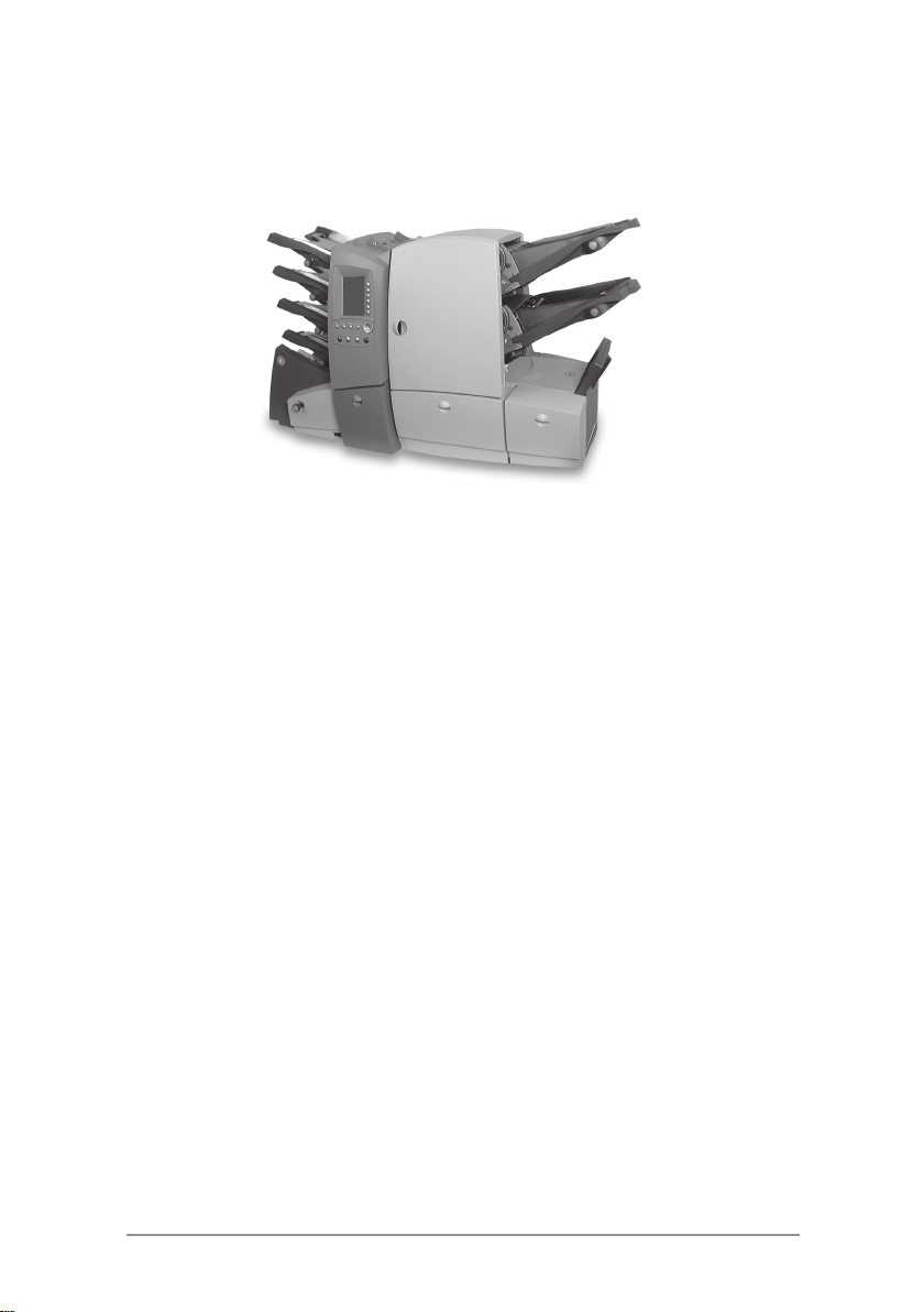
Machine Configurations
The following machine configurations are available, depending on
yourlocalmarket:
• Two Sheet Feeders Only
• Four Sheet Feeders Only
• Two Sheet Feeders and One Insert Feeder
• Two Sheet Feeders and Two Insert Feeders
• Four Sheet Feeders and One Insert Feeder
• Four Sheet Feeders and Two Insert Feeders
Each feeder location has its own letter designation which remains
the same irrespective of machine configuration. Therefore, machine
configurations with less than the full complement of feeders will use
feeder designations which are not in alphabetical sequence – this is
normal.
The processing speed will also vary depending on machine
configuration. See ‘Specifications’ in Chapter 7 for further details.
The illustration on the next page shows feeder locations and
designations.
In addition, an Optical Mark Recognition (OMR) option can be added
to any model. This allows control of machine functions and Mail
Piece make-up by ‘scanning’ material passing through the machine
for machine readable marks (OMR Marks). For further information,
refer to Chapter 5 of this guide.
This guide covers all models. If a function is dependent on machine
configuration, the accompanying text will explain this.
1-4 SV40221 Rev. C
Page 13
Introduction • 1
Sheet Feeders
A
B
C
D
E
Envelope Feeder
Feeder Configuration
Insert Feeders
Manual Feeder
H
G
F
1-5SV40221 Rev. C
Page 14
1 • Introduction
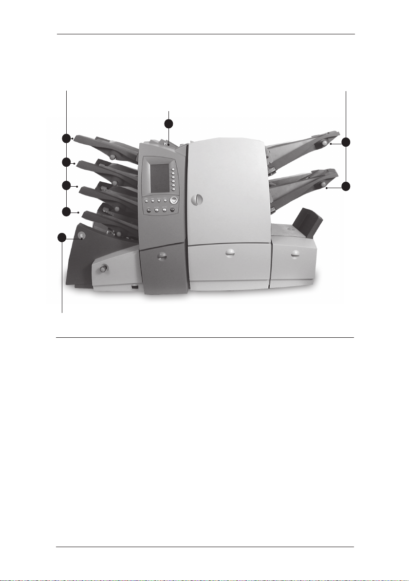
Machine Identification
32
1
9
8
7 6
Sheet Feeders
1
Use these feeders to feed sheets that require folding. A
double detect feature can be enabled which checks to see if
more than one sheet feeds (a double detect), giving security to
your mailings.
Depending on the job being run and availability of feeders,
there also is an option to ‘link’ these feeders so that when
the first feeder runs out of material, feed will automatically
switch to the next linked feeder. This allows a higher volume of
material to be processed before refilling is required.
Control Panel
2
This is where you enter commands to run the machine or
configure Job Settings. The control panel display also shows
you the machine status, loading instructions and details of the
job. See 'Control Panel' on the page 1-8 for more details.
4
5
1-6 SV40221 Rev. C
Page 15

Introduction • 1
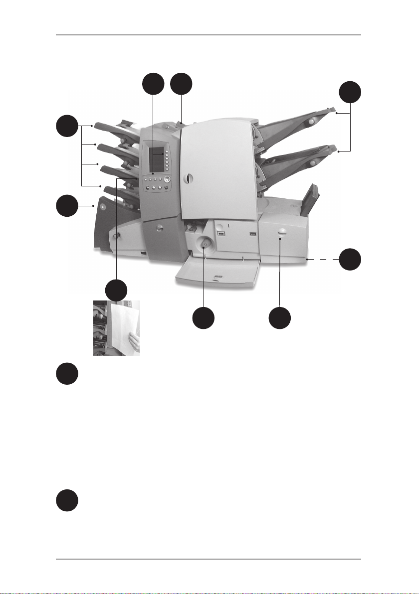
Manual Feeder (also known as Convenience Feeder or Daily
3
Mail Feeder)
Use this feeder to manually feed stapled or unstapled sets of
up to 5 sheets (see specifications, page 7-2). The machine
waits for each set to be manually fed before folding and
inserting the set automatically into the envelope. A Supervisor
can also configure the machine to place insert(s) within the set
if Insert Feeder(s) are fitted.
Insert Feeder(s) (not on all model configurations)
4
Use these feeders to add additional inserts to your envelope.
Inserts fed from these feeders cannot be folded by the
machine, so they must already be folded or be a size that
does not require folding.
Drop Stacker (not illustrated)
5
A fold down stacker is located at the exit from the machine
to collect the finished Mail Pieces. This unit can be latched
against the machine when not in use.
Power stacker (not illustrated)
This is an option which automatically collects and neatly
stacks finished Mail Pieces. It locates at the exit of the
machine, in place of the Drop Stacker.
Mailing Machine Interface (not illustrated)
This is an option which automatically transports Mail Pieces to
a Pitney Bowes Mailing Machine for postal ‘franking’.
Sealer Bottle
6
The sealer bottle is located inside an opening cover at the
front right side of the machine. It provides sealing solution to
the Envelope Sealer.
Manual Advance Knob
7
The Manual Advance Knob is located inside an opening cover
at the lower center of the machine. It can be used to manually
turn the machine mechanisms to assist in clearing a material
stoppage.
Measuring Scale
8
The scale is located on the left side of the machine near the
sheet feeders as an aid in measuring material and envelopes.
Envelope Feeder
9
This feeder feeds envelopes into the inserting area where they
are filled with the material requested from the other feeder(s).
1-7SV40221 Rev. C
Page 16

1 • Introduction
Control Panel
Control Panel Keys
Screen Keys
Navigation Keys
Reset Counters
If only piece count is displayed, press this key to reset the piece
count to zero. If both piece and batch counters are displayed,
pressing this key allows either or both counters to be reset.
Help
Press this key to view an electronic Quick Reference Guide giving
you quick access to basic information regarding operation of your
machine.
Cancel
Press this key to take you back to the previous screen. If you have
made changes or defined settings on the screen you are cancelling,
these will be lost. Multiple presses of the Cancel key will step you
back through the screens you have visited until you get back to the
Home Screen.
1-8 SV40221 Rev. C
Page 17

Introduction • 1
Home
Press this key to take you back to the Home Screen. The Home
Screen is where you can run jobs and is the starting point for
accessing the menus.
Start
Starts automatic operation.
Trial Piece
Press this key to run test piece(s) so that you can check the machine
setup. Trial Piece(s) must be run before automatic operation can
begin using the Start key. If double detection is in use, the machine
calibrates itself automatically as it runs the Trial Piece(s). If the job
includes an Outer Envelope, it will be unsealed so that the contents
can be easily checked.
Clear Deck
Press this key to drive the material through and out of the system. It
can be used to clear the machine ready for automatic operation after
a stoppage has occurred, etc.
Stop
Stops automatic operation at the end of the next cycle.
Navigation Keys (▲▼◄► OK)
These keys are used to move a highlighted area around the display.
Once the desired area is highlighted, press the OK key to select it.
The▲and▼navigationkeyscanalsobeusedtochangevaluesof
machine settings.
Screen Keys
These are the six round keys located directly to the right of the
display. These keys correspond to the changeable options on the
display alongside them and therefore are not labelled.
1-9SV40221 Rev. C
Page 18
1 • Introduction
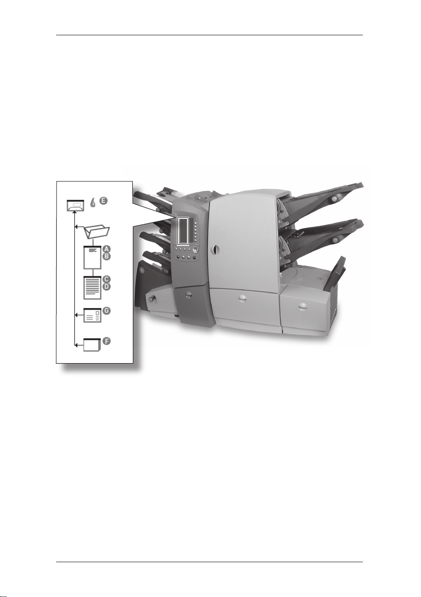
Mail Piece Icon Tree
The Mail Piece Icon Tree is located on the left side of the display.
It displays the Mailing Object Icons required, based on the Job
Definition.
The icons inform you which feeders to load, the type of object (sheet,
insert, etc.) to be loaded into each designated feeder and the loading
orientation of each object. It is therefore extremely important that you
become familiar with the icons themselves and the make-up of the
Mail Piece Icon Tree.
Loading Instructions
The▲and▼navigationkeyscanbeusedtoscrollthroughtheMail
Piece Icon Tree. When an item is highlighted, the machine will give
you the loading instructions associated with that item.
When you have viewed the loading instructions, press Home or
Cancel to return to the Home Screen or press Start or Trial Piece to
immediately begin processing.
1-10 SV40221 Rev. C
Page 19

Introduction • 1
Mail Piece Icon Tree Icons
Each Mailing Object Icon has one darker edge either at the top or
bottom that indicates the leading edge of the object when loaded into
the assigned feeder. The leading edge of an object is the edge that
feeds into the machine first.
For example, a sheet that must be loaded face
up with the top of the sheet leading would be
represented by a “face-up” sheet icon containing a
“leading edge” line on top.
A feeder assignment letter (A to G) will be placed
alongside the Mailing Object Icon to indicate which
feeder the object should be loaded into.
Two or more feeder assignment letters alongside a
single Mailing Object Icon indicate that linked feeders
have been selected. The item should be loaded in
all the feeders indicated. When one feeder becomes
empty, feed will automatically switch to the next
linked feeder and so on, in a continuous cycle.
If Double Detect is in use, the Double Detect Icon will
appear immediately to the left of the relevant Mailing
Object Icon.
If any Sheet Feeder(s) are programmed to feed
Pre-Collated Sets (multiple sheets), a modified icon
indicating multiple sheets will appear, together with
a number showing the number of sheets in the PreCollated Set.
On an Optical Mark Recognition (OMR) job, a
variable number of pages might be fed under
control of the OMR marks and so a small letter ‘n’
will appear in place of the number. Also, an asterisk
(*) will be displayed in the Mail Piece Icon Tree to
remind you that the job is an OMR job.
Lines between the Mailing Object Icons indicate the flow of material
through the machine.
3
n
Refer to the table on the following page as a reference to all the
icons that might appear on the Mail Piece Icon Tree.
1-11SV40221 Rev. C
Page 20

1 • Introduction
Envelope Icons
No Window,
Flap side up,
Flap Last
Window,
Flap side up,
Flap Last
Seal Icons
Seal On
Safe Seal On
Fold Icons
C Fold
(letter fold)
Z Fold
(accordion fold)
Single Fold
Double Fold
Insert Icons
Reply envelope,
Flap side down,
Flap First
Booklet,
Face Up,
Bound Edge First
Slip,
Face Up,
Bottom First
Pre-Folded Insert,
Open Edge Last
1-12 SV40221 Rev. C
Sheet Icons
No address,
Face Down,
Bottom First
No address,
Face Down,
Top First
No address,
Face Up,
Bottom First
No address,
Face Up,
Top First
Top address,
Face Down,
Bottom First
Top address,
Face Down,
Top First
Top address,
Face Up,
Bottom First
Top address,
Face Up,
Top First
Bottom address,
Face Down,
Bottom First
Bottom address,
Face Down,
Top First
Bottom address,
Face Up,
Bottom First
Bottom address,
Face Up,
Top First
Other Icons
A to
Double Detect On
H
Feeder Designators
OMR Job
*
Page 21
Introduction • 1
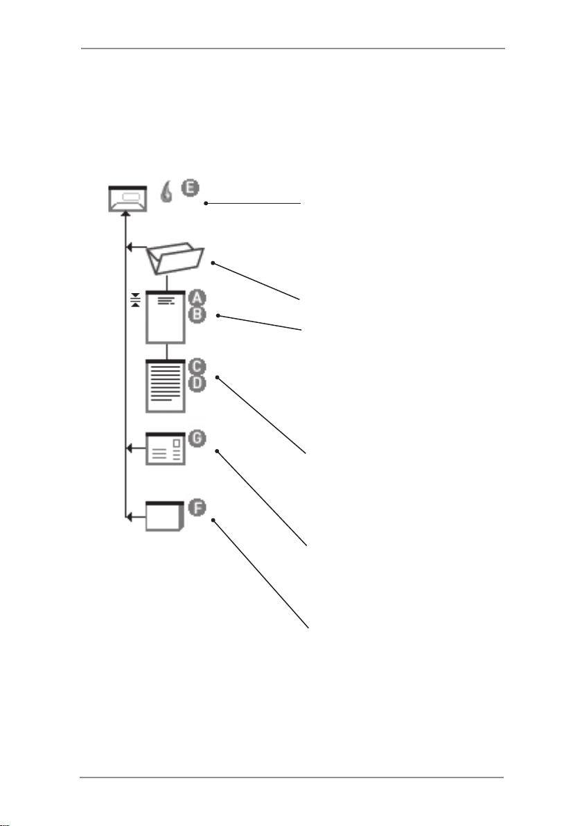
Mail Piece Icon Tree Example
An example Mail Piece Icon Tree is shown below. This explains the
information that is available and how it assists you in loading and
running a job.
Window Envelope
loaded Flap Side Up
fed Flap Last
Envelope sealing turned on
loaded into feeder E
C Fold selected
Prime Sheet with Top Address
loaded Face Up
fed Top First
loaded into feeders A and B
feeders A and B Linked
Double Detect turned on
Additional Sheet
loaded Face Up
fed Top First
loaded into feeders C and D
feeders C and D Linked
Reply Envelope
loaded Flap Side Down
fed Flap First
loaded into feeder G
Booklet
loaded Face Up
fed Bound Edge First
loaded into feeder F
1-13SV40221 Rev. C
Page 22

1 • Introduction
Common Terms
Throughout the machine screens and this guide, standard terms are
used to describe the elements of the Mail Piece and functions of the
equipment.
It is therefore important that you fully understand the following basic
termstogetthebestfromyourmachine:
MATERIAL
Sheet A single piece of paper that will require folding
by the machine before it is placed into an
envelope.
Pre-Collated Set A set of sheets printed in a collated sequence
i.e. sheet 1, sheet 2, sheet 3, etc.
Stack A pile of paper as received from the printer
that will be loaded into a feeder (or feeders)
on the machine. A stack might consist of
numerous individual Sheets or numerous
Pre-Collated Sets, depending on how it was
printed.
Prime Sheet or
Prime Set
Additional Sheet
or Additional Set
Fold Type Thestyleoffoldtobeapplied:
This sheet or set normally contains the
address. It will be positioned closest to the
envelope window, or the front face of a
windowless envelope.
Additional sheet(s) or set(s) can be added
to the Prime Sheet or Prime Set. They will
be fed from other Sheet Feeder(s) and are
placed into the envelope behind the Prime.
C Fold
Z Fold
Single Fold
Double Fold
1-14 SV40221 Rev. C
also know as ‘standard’
fold.
also known as
‘accordion’ fold.
one fold applied (usually
folded in half).
folded in half and then
in half again.
Page 23
Introduction • 1
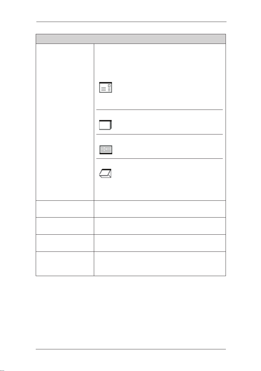
MATERIAL (continued)
Insert An item that doesn’t require folding before
being placed into an envelope. There are four
kindsofInserts:
Reply Envelope A return envelope
placed into the Outer
Envelope with the
other Mail Piece
contents.
Booklet An item with a
stapled and folded
binding edge.
Slip A single thickness
piece of paper or
card.
Pre-Folded Insert A sheet that has
been folded prior to
loading and requires
no further folding by
the machine.
Outer Envelope The envelope which contains all the items
placed into it by the machine.
Mail Piece A single assembled article of mail, usually an
envelope with correct contents.
Fan The process of flicking through a stack of
material to separate the items prior to loading.
Shingle The method of loading Inserts into a feeder in
a partially overlapped manner, like tiles on a
roof.
1-15SV40221 Rev. C
Page 24

1 • Introduction
MACHINE FUNCTIONS
Home Screen The initial screen displayed after turning
power on. From this screen you can select
pre-programmed Job Definitions, enter the
menu functions or run the machine.
Pressing the Home key on the Control Panel
will return you to this screen at any time.
Job Definition The collection of settings that define how a
Mail Piece is to be created by the machine.
Up to 20 Job Definitions can be stored for
instant recall.
Mail Piece Icon
Tree
Trial Piece Test piece run by the machine before
Safe Seal A modified sealing mode that allows better
Linked Feeders
A
D
to
F G
and
Optical Mark
Recognition
(OMR)
Situated down the left side of the display.
A graphical representation of the items that
make up the currently selected Job Definition.
automatic operation can be started. A Trial
Piece allows the machine to calibrate itself
and the Mail Piece make-up to be checked.
sealing of ‘poor’ envelopes. Safe Seal will
allow more time for the envelope flap gum to
soften, but will slow machine operation.
Allows more than one feeder to be configured
to run the same Stack. When the first feeder
runs out of material, feed will automatically
switch to the next ‘linked’ feeder, and so on,
in a continuous cycle. This allows empty
feeder(s) to be loaded while another linked
feeder is feeding material.
The process of controlling machine functions
and Mail Piece make-up by ‘scanning’
material passing through the machine for
machine readable marks (OMR Marks).
*
1-16 SV40221 Rev. C
Page 25
2 • Using the Menus
This chapter explains the Home Screen and the menu structure
accessed via the Control Panel
The Home Screen ..............................................................2-2
The Menu Structure ............................................................2-4
2-1SV40221 Rev. C
Page 26

2 • Using the Menus
2-2 SV40221 Rev. C
The Home Screen
The Home Screen is the first screen shown on the display after the
machine has finished powering up.
The last Job Definition selected is displayed with the relevant Mail
Piece Icon Tree on the left hand side.
The▲and▼navigationkeyscanbeusedtoscrollthroughthe
icon tree and highlight individual items. As you do this, the loading
instructions associated with the highlighted item will be shown.
From this screen you can run the job displayed. Alternatively, press
therelevantScreenKeyto:
● Select Job from those already programmed into the
machine. See page 3-3.
● InitiatetheSwiftStart™ feature. See page 3-8.
● SelecttheMenu ScreenKeytoaccess:
Operator Functions. See page 3-21.
Supervisor Functions. See page 4-2.
● YoucanalsousetheManual Feed feature. See page 3-11.
Page 27
Using the Menus • 2
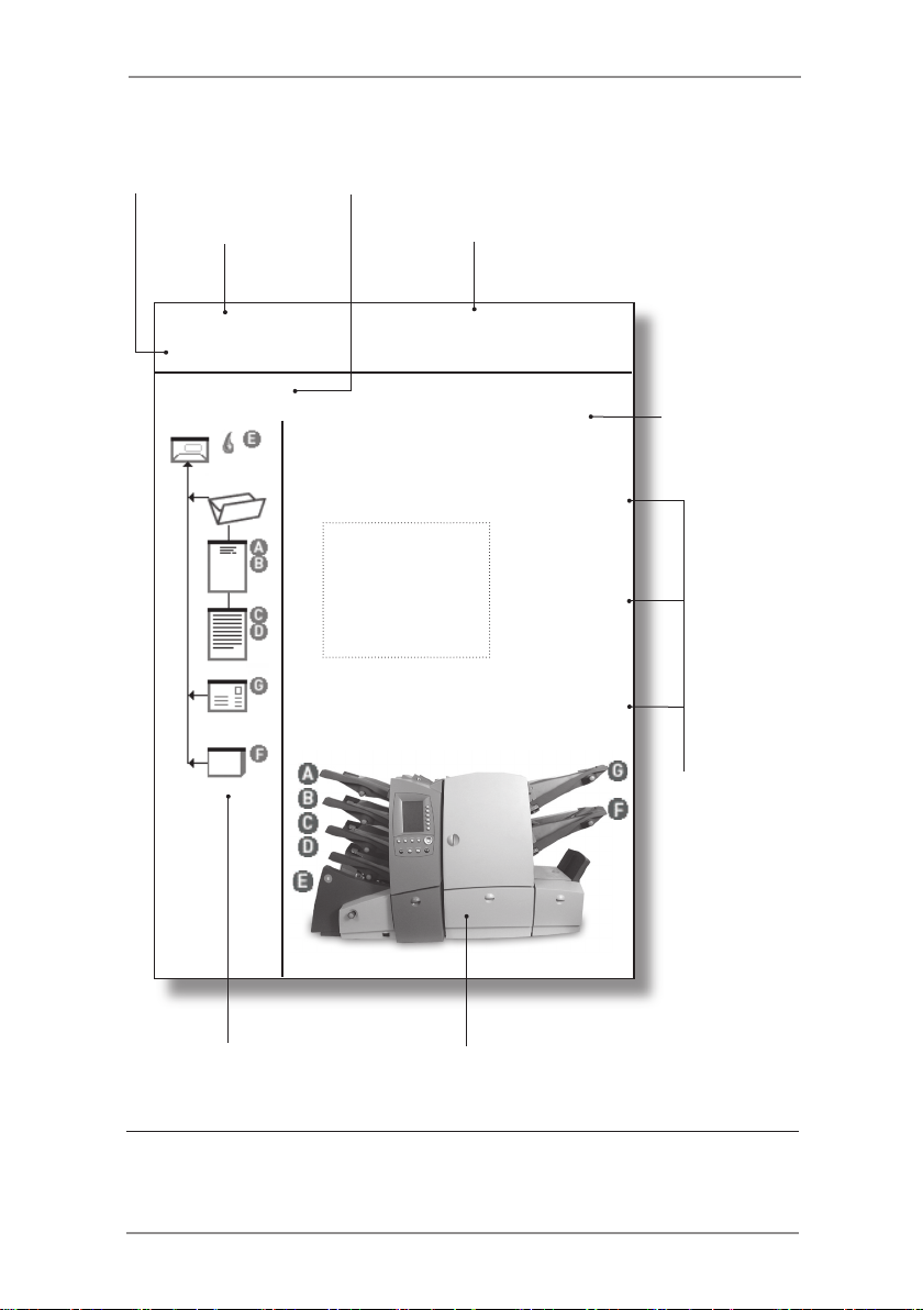
Machine
Status
Screen
Name
Home PieceCount:
READY BatchCount:
INVOICE A
Use▼,▲toviewloading
instructions
Name of
selected Job
Counter(s)
Job comments
text area
Select Job
SwiftStart
Menu
Instructional
Text
>
>
>
Screen
Key
Selections
Mail Piece Icon Tree Machine Graphic
The Home Screen
2-3SV40221 Rev. C
Page 28

2 • Using the Menus
2-4 SV40221 Rev. C
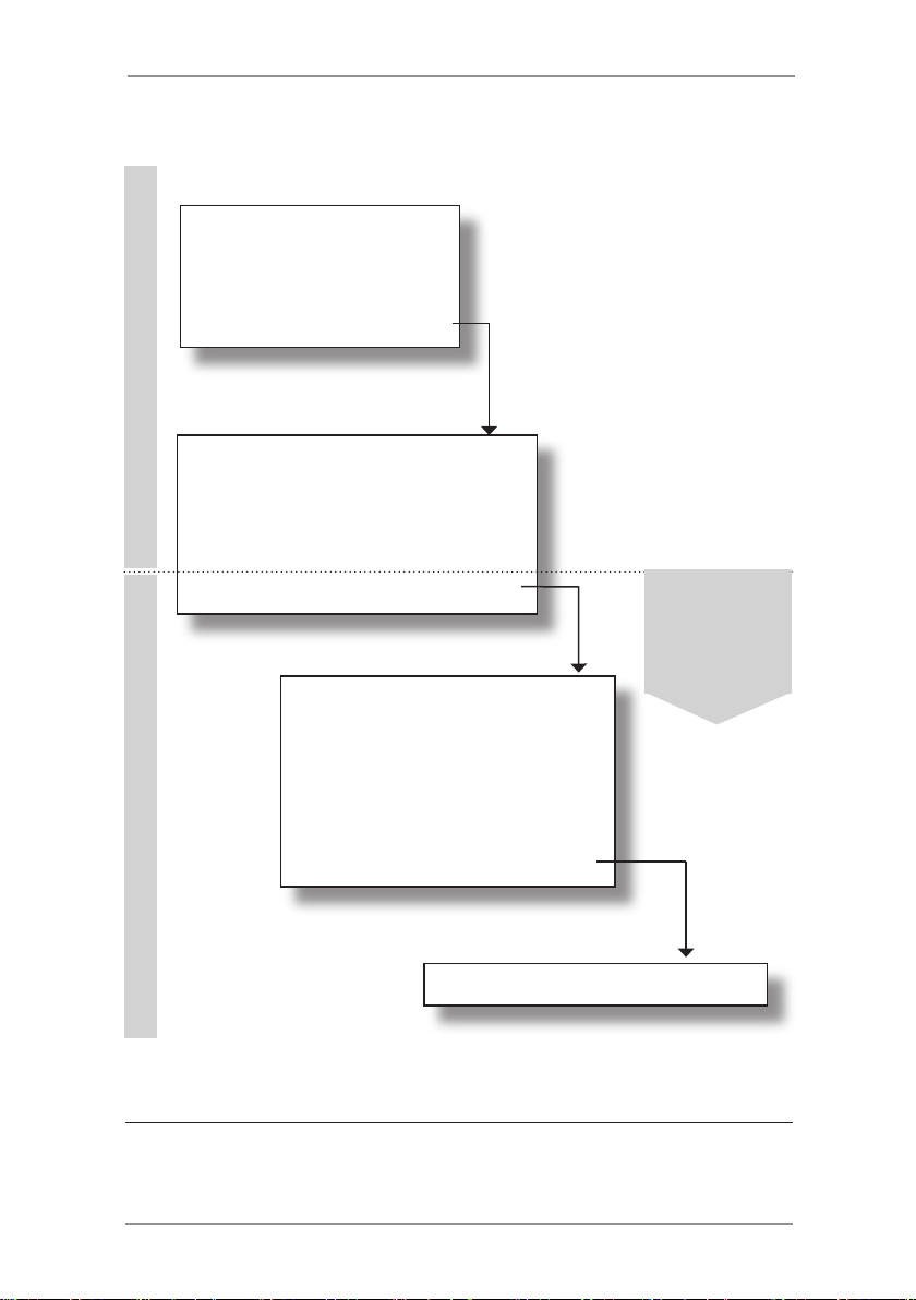
The Menu Structure
The diagram on the facing page shows the menu structure available
when you press the Menu Screen Key.
You will see that the menu follows a logical structure with similar
functions grouped together.
Themenustructureissplitintotwosections:
● ThefirstsectionisavailabletoallOperatorsandcontains
settings and adjustments that might be required when
running jobs on the machine.
● Thesecondsectionisonlyavailabletoa'Supervisor'upon
entry of a Supervisor Access Code. This section allows
supervisors to create, edit and delete jobs as well as set
more advanced features.
The following two chapters in this guide; 'Operator Functions' and
'Supervisor Functions' give details of the functions available to each
level of user.
Use this diagram as a quick reference to find the function(s) that you
require, then refer to the relevant page in this guide.
Each screen can be identified by its title located in the top left corner.
Page 29
Home Screen
Select Job (p.3-3) >
SwiftStart (p.3-8) >
Menu (p.3-21) >
Language (p.3-21) >
OPERATOR FUNCTIONSSUPERVISOR FUNCTIONS
Display Adjustments (p.3-21) >
Safe Seal (p.3-21) >
System Information (p.3-21) >
Supervisor Functions (p.4-1) >
Create Job (p.4-3) >
Edit Job (p.4-4) >
Create From (p.4-6) >
Delete Job (p.4-7) >
OMR Menu (p.4-8) >
System Menu (p.4-8) >
Using the Menus • 2
Supervisor
Functions
require a
Supervisor
Access Code
The Menu Structure
Manual Feed Setup (p.4-8) >
2-5SV40221 Rev. C
Page 30

2 • Using the Menus
2-6 SV40221 Rev. C
Page 31

3 • Operator Functions
This chapter lists the functions that can be carried out by an
Operator. Primarily, this includes selecting Job Definitions, running
the various operator modes and loading material.
About this Chapter ..............................................................3-2
Connecting Power ..............................................................3-2
Running a Job ....................................................................3-3
Selecting a Job ............................................................3-3
Loading Material ..........................................................3-4
Other Settings ..............................................................3-5
Running a Trial Piece ...................................................3-5
Automatic Processing ..................................................3-7
Batch Count .................................................................3-7
SwiftStart™.........................................................................3-8
Manual Feed.....................................................................3-11
Setting the Sheet Feeders ................................................3-14
Setting the Envelope Feeder ............................................3-16
Setting the Insert Feeder(s) ..............................................3-18
Filling the Envelope Sealer ...............................................3-20
Menu.................................................................................3-21
Language ...................................................................3-21
Display Adjustments ...................................................3-21
Safe Seal ...................................................................3-21
System Information ....................................................3-21
3-1SV40221 Rev. C
Page 32

3 • Operator Functions
About this Chapter
This chapter explains functions on the machine that can be carried
out by an Operator.Thisincludes:
• Selecting and running a pre-programmed Job Definition
• Using the SwiftStart™ mode
• Using the Manual Feeder
• Loading the feeders
• Filling the sealer
Functions that can only be carried out after entry of a Supervisor
Access Code are described in the next chapter, ‘Supervisor
Functions’.
Connecting Power
Read the safety information on
page 1-2 before connecting the machine.
Connect the power cord to the socket on the back of the machine.
Plug the power cord into a suitable power outlet. Make sure the
power outlet is near the machine and is easily accessible.
Turn the machine power switch
ON.
3-2 SV40221 Rev. C
Page 33

Operator Functions • 3
Running a Job
Selecting a Job
This section assumes the job to be run has already been created by
a Supervisor. If the job has not been created, refer to Create Job on
page 4-3.
When the machine is turned ON, a ‘Startup Screen’ showing an ‘hour
glass’ symbol will be displayed for a short time.
After a few seconds, the Home Screen will appear. The last Job
Definition selected will be loaded, with the message ‘Trial Piece
Required’ displayed at the top of the screen.
If the job loaded is not the one required, press the Select Job
Screen Key. A list of Job Definitions that have been created will
appear alphabetically on the screen. Then...
• If you are certain which job you want, press the Screen Key
alongside the desired job to select it immediately.
• Ifyouneedconfirmationofthejobdetails,usethe▲and
▼keystoscrollthroughthelist.Aseachjobishighlighted,
the Mail Piece Icon Tree and Job Comments (if entered) will
change to reflect the highlighted job. When you are certain
which job you want, press the corresponding Screen Key to
select it.
TIP: In either case, if the job you require is not on the
firstscreen,usethe◄and►keystomovetothe
screen containing the required job.
The selected job’s Mail Piece Icon Tree will now be
displayed. This shows the job make-up and the loading
orientation of material in the feeders. The message
‘Trial Piece Required’ will be shown at the top of the
display.
TIP:Onceajobisselected,youcanusethe▲and▼
keys to scroll through the icons on the Mail Piece Icon
Tree. As each icon is highlighted, loading instructions
related to the particular item will be displayed.
3-3SV40221 Rev. C
Page 34

3 • Operator Functions
Loading Material
If feeders are NOT linked...
Load material into all the feeders as indicated by the Mail Piece Icon
Tree (refer to setting the feeders on pages 3-14 to 3-19).
If feeders ARE linked...
For Job Definitions which contain linked feeders, the loading of
the feeders must be in the correct order to minimize the risk of the
sheets becoming out of sequence.
Insert Feeders
The uppermost Insert Feeder (G) should be loaded first. The
Inserts should be loaded as instructed by the loading instructions
on the control panel. If OMR marks are used on the inserts, the
marks must be face up and nearest to the front of the machine.
For C and Double folds
Place the complete stack of Sheets to be loaded into the Linked
Feeders face up next to the machine. Select the required
amount of sheets to be loaded into the first Sheet Feeder. Load
the sheets as indicated by the loading instructions on the control
panel into the uppermost linked Sheet Feeder. Take the next
required amount of sheets from the top of the stack and load
these into the feeder immediately below the previous feeder.
Repeat, if necessary, until all linked feeders are loaded.
For Single and Z folds
Place the complete stack of Sheets to be loaded into the Linked
Feeders face down next to the machine. Select the required
amount sheets to be loaded into the first Sheet Feeder. Load
the sheets as indicated by the loading instructions on the control
panel into the uppermost linked Sheet Feeder. Take the next
required amount for the top of the stack and load these into
the feeder immediately below the previous feeder. Repeat, if
necessary, until all linked feeders are loaded.
3-4 SV40221 Rev. C
Page 35

Operator Functions • 3
All of the Linked Feeders must be loaded in the same sequence in
which they become empty, this ensures that the sheets stay in the
correct order.
If the feeders are not loaded in the correct order, the machine will
displaythefollowingoptions:
Exclude
This option allows you to exclude a feeder from a run until
another Job Definition or Trial Piece is selected.
Resolve Feeder (Loading Error)
This option appears if a feeder has been loaded in an incorrect
sequence. Select Resolve Feeder to find out which feeder was
loaded in the wrong sequence.
Other Settings
If required, reset the item and/or batch counters by pressing the
Reset Counters key.
If necessary, fill the Sealer with sealing solution or water (see page
3-20).
If you are running an Optical Mark Recognition (OMR) job, the OMR
Scanners must be aligned to the OMR marks on the material being
run. Refer to page 5-22 for instructions.
Now run a Trial Piece as described in the following section.
Running a Trial Piece
A Trial Piece is required to enable you to check the Mail Piece
contents and to allow the machine to calibrate itself for the material
being run.
Press the Trial Piece key. The machine runs a single Mail Piece
which exits the machine unsealed so that you can check the
contents. The machine then asks if the Trial Piece is OK.
If the Trial Piece is OK, select Yes and follow the instructions in the
section ‘Automatic Processing’ on page 3-7.
3-5SV40221 Rev. C
Page 36

3 • Operator Functions
If the Trial Piece is NOT OK, select No and follow the on-screen
instructions to correct the error. You can adjust the address position,
fold panel length and/or the envelope stop position. The envelope
stop position will rarely need adjusting - for more information, see
page 6-15.
Once the adjustment is made and any further Trial Piece is OK, you
will be asked if you wish to save the changed settings as part of the
Job Definition.
If you choose Yes...
The machine will save the changed setting(s) as part of the
current job. Next time the original Job Definition is selected,
the modified adjustment(s) will be remembered.
A Supervisor Access Code (see page 4-2) will be requested,
as you are editing an existing Job Definition.
If you choose No...
The adjustment(s) you have just changed will only be
retained while you are running the current job. If another Job
Definition is selected or if power is turned off, next time the
original Job Definition is selected, the modified adjustment(s)
will have returned to the value saved within the Job
Definition.
TIPS:
If you reload material during a run which seems to have
different characteristics (weight, color shade, etc.), or if
you have any problems with double detect, run another
Trial Piece. This allows the machine to recalibrate the
double detect function for the new material in case the
batches vary slightly.
After running a Trial Piece, the options Fill Now, Fill
Later and Exclude will be displayed if a feeder which
is used within the job definition is not loaded. You can
either select ‘Fill Now’ and load the relevant feeder
immediately, select ‘Fill Later’ which lets you begin
running the selected job without immediately loading the
relevant feeder, or ‘Exclude’ to exclude the feeder from
the current run.
3-6 SV40221 Rev. C
Page 37

Operator Functions • 3
Automatic Processing
After confirming a Trial Piece is OK...
Press the Start key to begin automatic operation.
Themachinewilloperateuntil:
● materialrunsout
● theStopkeyispressed
● thebatchcountisreached(ifbatchcountisbeingused)
● thefirstSelectFeedsheetisfed(iftheSelectFeedfeature
in OMR is being used).
● theOMR‘Stop’featureisactivated(seepage5-4formore
details).
Batch Count
If the Batch Count function was set when the job was created, the
machine will stop automatically after processing the required number
of Mail Pieces. Remove the batch of Mail Pieces and press Start to
resume processing.
3-7SV40221 Rev. C
Page 38

3 • Operator Functions
SwiftStart™
SwiftStart™ allows you to load material into the feeders and run a
simple job with minimal setup information.
The job can then either be run without saving it to the machine’s
memory, or a Supervisor can name and save the Job Definition for
future recall as and when required.
TIP:
SwiftStart™ can be used as a way to quickly
programme a new Job Definition. Load material and run
SwiftStart™. A Supervisor can save the new job and
then use the Edit Job function (see page 4-4) to make
minor changes, if necessary.
Constraints and Requirements
• Only use closed flap envelopes.
• Feeds only single sheets from each Sheet Feeder.
• This mode cannot be used to run fold only or inserts only.
• You cannot link Sheet Feeders in this mode.
• The Envelope Sealer is always on (except for the Trial
Piece).
• The Batch Count is always off.
• The Sheet Length must be 11-1/2” (292mm).
• This mode will not work with OMR.
Loading Material for SwiftStart™
Loading Sheet Feeders
Depending on your envelope depth, the machine will automatically
select the fold type – Single or C (standard) fold.
For example, a standard sheet (8-1/2” x11”) inserted into a #10
envelope will receive a C fold, whereas a standard sheet inserted
into a 6” x 9” envelope will only receive a Single fold.
3-8 SV40221 Rev. C
Page 39

For a C fold Job: Load the
Sheet Feeders from the
top feeder downwards, in
sequence (prime sheet in top
feeder).
Load Sheets Face Up and Top
First.
For a Single fold job: Load the
Sheet Feeders from the bottom
feeder upwards, in sequence
(prime sheet in bottom feeder).
Load Sheets Face Down and
Bottom First.
Operator Functions • 3
Loading Insert Feeder(s)
If either or both Insert Feeders are loaded with material when
SwiftStart is selected, the machine will feed the Inserts and make
them part of the SwiftStart™ job.
For a single Insert, load Insert Feeder F. For two Inserts, load Insert
Feeders F and G.
Booklets must be loaded into Insert Feeder F only and should be
loaded with the binding edge first.
Pre-folded Inserts should be fed with the open edge last.
Reply Envelopes (BRE’s) must be loaded flap side down, flap first.
Loading Envelope Feeder
Envelopes are loaded into Envelope
Feeder E flap side up, flap last.
3-9SV40221 Rev. C
Page 40

3 • Operator Functions
SwiftStart™ Operation
Load material as previously described and select SwiftStart. The
machine will feed an envelope and depending on the depth of the
envelope, will automatically select the fold type – Single or C fold.
If the envelope depth cannot be accurately determined, the machine
will stop and request you to enter the measurement manually.
A Trial Piece is automatically produced, enabling you to check the
job and to allow the machine to calibrate itself for the material being
run.
During this process, if the material in any of the feeders is too
heavy, the Double Detect for the relevant feeder(s) will be turned off
automatically. This will be indicated by a message on the display.
The machine will ask if the Trial Piece is OK.
If the Trial Piece is OK, select Yes and follow the instructions in the
section ‘Saving a SwiftStart™ Job’ below.
If the Trial Piece is NOT OK, select No and follow the on-screen
instructions to correct the error. You can adjust the address position,
fold panel length and/or the envelope stop position. The envelope
stop position will rarely need adjusting - for more information, see
page 6-15.
Saving a SwiftStart™ Job
After confirming a Trial Piece is OK, you will be given the option to
save the current SwiftStart™ setup as a Job Definition for recall in
future. This function requires Supervisor level access (see page 4-2).
If you do NOT save the SwiftStart™ setup, it will only be retained
while you are running the current job. If another Job Definition is
selected or if power is turned off, the SwiftStart™ settings will be lost.
Automatic Processing
Whether you have chosen to save the SwiftStart™ job or not, you
cannowbeginautomaticprocessinginthenormalway:
Press the Start key to begin automatic operation.
The machine will operate until either material runs out or the Stop
key is pressed.
3-10 SV40221 Rev. C
Page 41

Operator Functions • 3
Manual Feed
Manual Feed allows you to feed stapled or unstapled sets of up
to 5 sheets of 20 lb. (80g/m2) to a maximum total weight of
100 lb. (400g/m2). The sets are fed by hand, one set at a time, for
processing by the machine.
Using the Manual Feed automatically turns off all Sheet Feeders.
You can, however, use the Insert Feeder(s) if they have been
enabled by a Supervisor using the Manual Feed Setup explained on
page 4-8.
Constraints and Requirements
• Only use closed flap envelopes.
• This mode cannot be used to run fold only or inserts only.
• Sheet Feeders do not operate in this mode.
• The Batch Count is always off.
• Sets should contain sheets of the same length.
• This mode will not work with OMR.
Loading Material for Manual Feed Mode
Loading Insert Feeder(s)
Insert Feeder(s) will only operate if they have been enabled by a
Supervisor using the Manual Feed Setup explained on page 4-8 of
this guide.
For a single Insert, load Insert Feeder F. For two Inserts, load Insert
Feeders F and G.
Booklets must be loaded into Insert Feeder F only and should be
loaded with the bound edge first.
Pre-folded Inserts should be fed with the open edge last.
Reply Envelopes (BRE’s) must be loaded flap side down, flap first.
Loading Envelope Feeder
Envelopes are loaded into Envelope Feeder E flap side up, flap last.
3-11SV40221 Rev. C
Page 42

3 • Operator Functions
Manual Feed Operation
Make sure Envelopes and Inserts (if required) are loaded as
previously described.
You must now decide how to feed the set into the Manual Feeder, as
this depends on the type of fold the set requires.
Depending on your Envelope depth and Sheet length, the machine
will automatically select the fold type – Single, C or double fold.
Forexample:
8-1/2” x 11” sheets inserted into a #10 envelope will receive a C fold.
8-1/2” x 11” sheets inserted into a 6” x 9” envelope will receive a
Single fold.
Sheets over 12” (305mm) long inserted into a #10 envelope will need
a Double fold.
UsethefollowinglistasaguideforfeedingtheManualFeedset:
C Fold Feed the set Face Up, Top First
Single Fold Feed the set Face Down, Bottom First
Double Fold Feed the set Face Up, Top First
Set the Manual Feeder side
guides to control the sets to
be fed. The guides are selfcentring.
Take one set and feed it gently
into the Manual Feeder until the
machine automatically starts
and draws the set from you.
A Trial Piece is produced, enabling you to check the job setup. The
machine will ask if the Trial Piece is OK.
If the Trial Piece is OK, select Yes and refer to ‘Manually Feeding
Further Sets’ on the next page.
If the Trial Piece is NOT OK, select No and follow the on-screen
instructions to correct the error. You can adjust the address position,
fold panel length and/or the envelope stop position. The envelope
stop position will rarely need adjusting - for more information, see
page 6-15.
3-12 SV40221 Rev. C
Page 43

Operator Functions • 3
Manually Feeding Further Sets
After confirming a Trial Piece is OK, the machine will remember its
settings and process further manually fed sets automatically.
While the motor runs, the machine will remain in Manual Feed mode.
If no further sets are fed whilst the motor is running, after a brief
delay, the motor stops and the machine reverts to the previous Job
Definition selected.
If you wish to leave Manual Feed mode while the motor is running,
press Stop once.
3-13SV40221 Rev. C
Page 44

3 • Operator Functions
Setting the Sheet Feeders
Sheet Feeders A to D feed sheets that require folding by the
machine.
The Mail Piece Icon Tree for the job being run will show which
feeders need to be loaded and the sheet orientation. If you need help
understanding the sheet icons, refer to page 1-12 of this guide.
The Prime Sheet or Set (normally containing the address) will be fed
from the top feeder for C or Double Fold jobs and from the bottom
feeder for single or Z fold jobs. This will be indicated by the Mail
Piece Icon Tree.
Sheet Feeders can feed single Sheets or Pre-Collated Sets,
depending on job setup. The Mail Piece Icon Tree will tell you the
quantity of sheets that the machine is programmed to run from
each feeder if Pre-Collated sets are programmed. If you need help
understanding the terms Sheet or Pre-Collated Set, refer to page
1-14 of this guide.
1. Adjust the side guides to
the width of the material
being fed using the Side
Guide Adjustment Knob,
then back-off 1/4 of a turn.
This will set the correct
clearance between the
guides and sheets.
2. Take the relevant Stack of
sheets and fan it to ensure
individual sheets are not
stuck together.
3-14 SV40221 Rev. C
Page 45

Operator Functions • 3
3. Jog the stack back into
alignment.
4. The Mail Piece Icon Tree will show the correct orientation of the
sheets in the Stack. Make sure you load sheets in the orientation
indicated.
5. The Sheet Feeders take
the paper Stack in a similar
way to a photocopier paper
cassette.
Place the Stack onto the
deck of the feeder.
Depress the Stack and
slide it fully under the feed
roller.
TIP:
Take care setting the side guides, as incorrect
adjustment can adversely affect machine performance.
Also, when reloading material, check the side guide
setting has not been disturbed.
3-15SV40221 Rev. C
Page 46

3 • Operator Functions
Setting the Envelope Feeder
Envelope Feeder E feeds the Outer Envelope for the inserting job
being run.
The Mail Piece Icon Tree for the Job Definition being run will show
if the feeder needs to be loaded and the envelope orientation. If you
need help understanding the envelope icons, refer to page 1-12 of
this guide.
1. Press the Envelope
Feeder loading switch to
lower the feeder tray ready
for loading.
2. Adjust the side guides to
the width of the envelopes
being fed using the Side
Guide Adjustment Knob,
then back off 1/4 of a turn.
This will set the correct
clearance between the
guides and envelopes.
3. Take the stack of
envelopes and fan it
to ensure individual
envelopes are not stuck
together.
3-16 SV40221 Rev. C
Page 47

4. Place the stack of
envelopes into the feeder
with the flap side up and
flap last.
5. Press the Envelope
Feeder loading switch
again to raise the envelope
stack to the normal feeding
position.
Operator Functions • 3
TIP:
To quickly load envelopes during a run, without the need
to stop and start the machine...
• Press the Envelope Feeder loading switch to
lower the feeder tray.
• Load envelopes as described above.
• Press the Envelope Feeder loading switch
again. The envelope stack will rise to the normal
feeding position and processing will continue
automatically.
3-17SV40221 Rev. C
Page 48

3 • Operator Functions
Setting the Insert Feeder(s)
Insert Feeders F and G feed items that do not require folding by the
machine. Depending on configuration, your machine may have no
Insert Feeders, one Insert Feeder or two Insert Feeders.
Insert Feeder F is capable of feeding thicker Inserts than Insert
Feeder G. Therefore, booklets must only be fed from Feeder F.
The Mail Piece Icon Tree for the job being run will show if the feeder
needs to be loaded and the Insert orientation. If you need help
understanding the Insert icons, refer to page 1-12 of this guide.
1. Adjust the side guides to
the width of the Inserts
being fed using the Side
Guide Adjustment Knob,
then back-off 1/4 of a turn.
This will set the correct
clearance between the
guides and Inserts.
2. Refer to the labels located on each Insert Feeder. Match your
insert type (Slip, Reply Envelope, Pre-Folded or Booklet) with the
relevant icon and color indicator on each label. Where a range of
settings is indicated on the label, the thicker the insert, the higher
the number or letter that should be selected.
i.e., The blue Booklet range runs from 6 to 9 and from C to D.
A thin Booklet might be set to 6 or 7 and C, whereas a thick
booklet might need settings 9 and D to run effectively.
3. Set the blue separator
gap lever to the number
required.
3-18 SV40221 Rev. C
Page 49

4. Set the blue separator
shield lever to the letter
required.
5. Take the stack of inserts
and fan it to ensure
individual Inserts are not
stuck together.
6. ‘Shingle’ the inserts to be
run so that they look like
the photograph on the right
and place them onto the
feed deck.
The Mail Piece Icon Tree
will show the correct
orientation of the Inserts.
If using OMR marks on
Inserts, always load with
the OMR marks facing
upwards and with the
marks towards the front
(operator) side of the
machine.
7. Let the Wedge slide down
behind the stack so that
the Inserts are supported.
Operator Functions • 3
Note: If Insert Feeders F and G are linked (running the same
inserts), make sure the lever settings in steps 3 and 4 are
set the same on both feeders.
3-19SV40221 Rev. C
Page 50

3 • Operator Functions
Filling the Envelope Sealer
Make sure the Envelope Sealer is filled with Sealing Solution before
running a job that has sealing turned on.
When the sealer needs refilling, a warning message will
automatically appear on the display and, if sealing, the sealing icon
will flash.
AddSealingSolutioninthefollowingway:
Hinge open the Sealer Bottle
Cover located at the front right
hand side of the machine.
Remove the bottle.
Unscrew the cap and fill the bottle with Sealing Solution.
Refit the cap and place the bottle back into the machine.
Close the Sealer Bottle Cover.
TIPS:
If filling the Envelope Sealer for the first time, or if the
sealer has been allowed to completely empty, you
should allow time for the solution to soak through the
sealer mechanism before processing material.
The use of water in the sealer is not recommended.
Sealing Solution improves sealing performance and
minimizes growth of algae and scale build-up. It can be
purchased from your machine supplier.
When refitting the Sealer Bottle cap, the ‘pointed’ part of
the cap fits into the bottle neck and the cap screws into
place.
3-20 SV40221 Rev. C
Page 51

Operator Functions • 3
Menu
Select the Menu Screen Key to access the following Operator
Optionswithinthemenustructure:
• Language
• Display Adjustments
• Safe Seal
• System Information
Language
When this option is selected, a choice of languages will be displayed.
Choose the required language from the list and all display text will
change to the selected language.
This is a temporary setting. Switching the machine Off and then back
On will revert to the default language. (The default language is set to
your preference by your local service engineer at installation).
Display Adjustments
Select this option and follow the simple on-screen instructions to
change the contrast or brightness levels of the display to suit your
needs.
Safe Seal
This option allows you to switch Safe Seal on or off. When on, the
Safe Seal icon appears on the Mail Piece Icon Tree alongside
the Outer Envelope icon.
Safe Seal allows more time for moisture to soften the gum on the
Outer Envelope, allowing it to become more sticky. This function
therefore improves sealing of certain types of envelope but will slow
the machine down.
System Information
This screen displays information such as machine serial number,
your local service and supplies telephone number, software versions
and total item count.
3-21SV40221 Rev. C
Page 52

3 • Operator Functions
3-22 SV40221 Rev. C
Page 53

4 • Supervisor Functions
This chapter lists the functions that can be carried out by a
Supervisor. Primarily this includes creating, editing and deleting jobs.
About this Chapter ..............................................................4-2
Supervisor Access Code ....................................................4-2
Create Job ..........................................................................4-3
Edit Job...............................................................................4-4
Create From .......................................................................4-6
Delete Job ..........................................................................4-7
OMR Menu .........................................................................4-8
System Menu......................................................................4-8
Manual Feed Setup ............................................................4-8
4-1SV40221 Rev. C
Page 54

4 • Supervisor Functions
About this Chapter
This chapter describes the functions available within the Supervisor
Functions menu.
All of the functions are set by following a sequence of screens and
answering simple questions presented on the display. Therefore,
this chapter does not take you through every function step by step. It
gives you background information on the function and offers helpful
tips to get the best out of your machine.
Supervisor Access Code
Before you can access any of the functions in this menu you must
enter a Supervisor Access Code. This prevents unauthorized access
to functions mainly related to administration of jobs and OMR.
Your installing engineer will tell you the Supervisor Access Code. If
you wish, you can write it in the box on this page as a reminder.
However, please be aware that this is then available to anyone
using this Operator Guide and so you may wish to make a note
of it and keep it in a more secure location.
The Supervisor Access Code cannot be changed from the one given
to you by the installing engineer.
SupervisorAccessCode:
Entering the Code
WhenaskedtoentertheSupervisorAccessCode,usethe▲▼◄►
keys to highlight the first digit of the code on the Numeric Matrix
displayed, and confirm this digit by pressing OK. Repeat for the
second digit. When complete, select Finished.
4-2 SV40221 Rev. C
Page 55

Supervisor Functions • 4
Create Job
What is it?
This function allows a Supervisor to create new Job Definitions to be
stored within the machine’s memory for easy access by an Operator.
The machine can store a maximum of 20 Job Definitions.
Where is it?
From the Home Screen...
select Menu
select Supervisor Functions
enter the Supervisor Access Code (see page 4-2)
select Create Job
Action…
The machine will ask you a number of specific easy to answer
questions about the make up of the finished Mail Piece in order to
create the Job Definition.
Some of the questions asked will be based on the answers
previously given and so the sequence will vary from job to job. As
you create the job, the Mail Piece Icon Tree will be built on the left
side of the display. This shows how to load material into each feeder.
Once the job is created, named and any comments entered, you
must select Save to store it in the machine’s memory.
TIPS:
Placing a job description in the job comments will make
it easy for an Operator to select the correct job.
Use the Batch Counter if you want to automatically
process a pre-defined number of Mail Pieces. When the
Batch Count is complete, the machine will stop, allowing
the Operator to empty the stacker. Pressing Start will
begin processing of the next batch.
If you are using OMR within a job, an OMR code must
be pre-programmed into the machine’s memory. For
details of programming OMR codes, refer to Chapter 5.
4-3SV40221 Rev. C
Page 56

4 • Supervisor Functions
Edit Job
What is it?
Edit Job allows a Supervisor to add and delete items within an
existing Job Definition. It also lets a Supervisor alter the job setup
such as batch count, job comments and job name.
The Edit Job function is used to change a Job Definition, and so
always over-writes the original Job Definition in the machine’s
memory (even if the Job Name has been edited). If you wish to
create a NEW Job Definition which is similar to an existing job and
leave the existing Job Definition untouched, use the Create From
function described on page 4-6.
Where is it?
From the Home Screen...
select Menu
select Supervisor Functions
enter the Supervisor Access Code (see page 4-2)
select Edit Job
Action…
Once Edit Job has been selected, choose the Job Definition you
wish to edit from the alphabetical job list using the ▲▼◄► keys in
the normal way.
Edit Job allows a Supervisor to modify all Job Definition parameters
except for adding or removing the Outer Envelope and the Prime
Sheet or Set.
Highlight the item you wish to edit by scrolling through the Mail Piece
IconTreeusingthe▲▼keys.
To add an Additional Sheet/Set or a second Insert, highlight the icon
in the Mail Piece Icon Tree immediately adjacent to the point you
wish to add the new item, then select Add Item After or Add Item
Before as applicable.
To add an Insert to a job currently without Inserts, select Add Insert.
4-4 SV40221 Rev. C
Page 57

Supervisor Functions • 4
TIPS:
Highlight the Job Nametoeditthefollowingitems:
Job Name
Job Comments
Batch Counter
Maximum Sheet Length
OMR feature set up
Highlight the Envelope icon to edit envelope and
sealing settings.
The Outer Envelope and Prime Sheet cannot be added
or deleted.
Don’t forget to edit the job comments to correspond to
your revised job setup!
When editing a job, it is recommended that you
start at the top of the Mail Piece Icon Tree and work
downwards.
4-5SV40221 Rev. C
Page 58

4 • Supervisor Functions
Create From
What is it?
A Supervisor can use the Create From function to create a NEW Job
Definition which is SIMILAR to an existing job and leave the existing
Job Definition untouched. This can save time programming a new
Job Definition when it is almost identical to an existing job but for a
small change such as an extra Insert or Sheet, etc.
The machine will copy the existing Job Definition and ask for the new
job to be named. It will then allow you to edit the new job to meet the
slightly changed requirements.
Where is it?
From the Home Screen...
select Menu
select Supervisor Functions
enter the Supervisor Access Code (see page 4-2)
select Create From
Action…
Once Create From has been selected, choose the Job Definition
you wish to use as the basis of the new job from the alphabetical job
list using the ▲▼◄► keys in the normal way.
Once the Job Definition that you are ‘creating from’ has been
selected, the machine will prompt you to enter a new Job Name (as
no two Job Definitions can have the same name).
After the Job Name has been entered, the machine will ask you to
enter the Job Comments. The following screens will then be as in
Edit Job described on page 4-4.
TIPS:
The machine’s memory holds a maximum of 20 Job
Definitions.
All the tips for Edit Job (page 4-5) also apply.
4-6 SV40221 Rev. C
Page 59

Supervisor Functions • 4
Delete Job
What is it?
Delete Job allows a Supervisor to remove a stored Job Definition
permanently from the machine’s memory.
Where is it?
From the Home Screen...
select Menu
select Supervisor Functions
enter the Supervisor Access Code (see page 4-2)
select Delete Job
Action…
Once Delete Job has been selected, choose the Job Definition you
wish to delete from the alphabetical job list using the ▲▼◄► keys
in the normal way.
Once the required Job Definition is selected, a message will be
displayed which requires confirmation before the job is deleted.
TIP:
Make sure the Job Definition you are deleting is the
correct job! Once deleted, it cannot be retrieved.
4-7SV40221 Rev. C
Page 60

4 • Supervisor Functions
OMR Menu
This function lets a Supervisor setup Optical Mark Recognition
(OMR) codes for inclusion within Job Definitions.
All OMR functions are explained fully within Chapter 5 - OMR.
System Menu
What is it?
ThismenuletsaSupervisoradjustthefollowingsystemsetting:
● ManualFeedSetup
Where is it?
From the Home Screen...
select Menu
select Supervisor Functions
enter the Supervisor Access Code (see page 4-2)
select System Menu
Manual Feed Setup
Ignore/Feed Inserts
This function lets a Supervisor choose whether or not the Insert
Feeder(s) are active when a Manual Feed operation is carried out.
The default setting is for both Insert Feeders to be ignored with a
Manual Feed. Changing this setting will feed Insert(s) from either or
both Insert Feeders, if they are loaded.
Seal Option
This option lets a Supervisor choose to use Seal; Safe Seal (see
page 3-21) or not to Seal the Outer Envelope when a Manual Feed
operation is carried out.
For more details of Manual Feed see page 3-11 of this guide.
4-8 SV40221 Rev. C
Page 61

5 • Optical Mark
Recognition (OMR)
This chapter gives background and setup information for using
Optical Mark Recognition (OMR) on a machine equipped with the
OMR option.
OMR Availability .................................................................5-2
What is OMR? ....................................................................5-2
OMR Marks Available .........................................................5-3
OMR Mark Options .............................................................5-6
OMR Specifications ............................................................5-9
Creating, Deleting and Viewing OMR Codes ...................5-13
Create New OMR Code....................................................5-14
Delete OMR Code ............................................................5-16
View OMR Code ...............................................................5-17
Creating an OMR Job .......................................................5-18
OMR Scanner Adjustments .............................................5-22
5-1SV40221 Rev. C
Page 62

5 • Optical Mark Recognition (OMR)
OMR Availability
Your machine can be equipped with Optical Mark Recognition
(OMR) functionality either on installation or as an added option after
purchase. The machine can store up to 10 different codes for you to
select when creating Job Definitions that use OMR.
What is OMR?
An OMR mark is normally a dark solid
line on a sheet of light colored paper
that is perpendicular to the direction of
travel of the paper. This line must be
sufficiently thick, dense and placed in the
correct area to trigger the OMR scanner
on the system.
There are many different OMR options
available to you, from a Single Mark
option to Multi-Mark options, which have
a maximum of 24 marks.
The OMR scanner, working with the
OMR system software, checks for one or
more different marks on the sheets while they are being fed through
the system. The tracking of these OMR marks by the system will aid
the integrity of your mailing through error checking, so generally the
more marks you use, the better the integrity of your Mail Piece.
As mentioned on page 7-3 of this guide, there are limits on how
many sheets the machine can fold at one time. These limits are
dependent on the paper weight of your sheets, and fold type
selected, and should not be exceeded. It is therefore strongly
recommended that, when programming your system to print your
OMR sheets, these limits are taken into account. If these limits are
exceeded, it could result in a material stoppage or damage to the
material and the machine.
Typical
OMR marks
5-2 SV40221 Rev. C
Page 63

Optical Mark Recognition (OMR) • 5
OMR Marks Available
This section gives brief descriptions of the OMR Marks that can be
allocated to an OMR Code and lists the options available for use with
each mark. The section following, OMR Mark Options on page 5-6
then gives greater detail of each option.
NOTE: Some marks within this section are available as added
features which expand OMR capability. Contact your machine
supplier for details. OMR features available will vary depending on
the country you are in.
BM - Benchmark
This is a mandatory mark within the Multi-Mark option, it must be
either the first or last mark of the code and will appear on every page
within the prime or matched set.
This mark may only be selected once within the code.
SAF - Safety
This mark improves the integrity of your Mail Piece. It can be placed
anywhere within the code but benefits from being at the opposite end
of the code to the Benchmark.
When the Safety mark is placed in this position with the option
Always Present, the machine will automatically detect the code
length. This makes creating jobs using this code easier. Otherwise,
the machine will ask for a code length when creating a job.
This mark may appear more than once within the code.
Optionsavailable:
• Always Present or Never Present
BOC - Beginning of Collation
This mark indicates that it is the first sheet fed within a set. This mark
may only be selected once within the code.
Optionsavailable:
• Present or Absent
5-3SV40221 Rev. C
Page 64

5 • Optical Mark Recognition (OMR)
EOC - End of Collation
This is a mandatory mark within the Muti-Mark option, when used
on the Prime Sheet Set. This mark indicates that it is the last sheet
fed within the OMR set. This is the only mark used when using the
Single Mark option and can only be selected once within the code.
Optionsavailable:
• Present or Absent
STP - Stop
This mark is a processing feature which tells the machine to stop
once the completed Mail Piece has exited the machine.
Optionsavailable:
• Present or Absent
• All Sheets, Page 1 Only or Last Page Only
• Marked Piece to be left Unsealed (Yes or No)
SF(n) - Select Feed
These marks instruct the machine to select material from specified
feeders.
This feature is only available to select sheets when C, Z and Single
folds are used and the material is under 12“ (305mm) in length.
Selectively fed inserts are available for all types of folds and sheet
lengths within the specifications of the machine.
Up to 8 Select Feed Marks can be within the code. Up to 5 of these
marks can be allocated to specified feeders when creating a Job
Definition. The remaining marks will be ignored within that job.
Allowing 8 Select Feed Marks to be used gives greater flexibility in
reusing existing codes from production type machines which may
have a greater number of feeders.
Optionsavailable:
• Present or Absent
• All Sheets, Page 1 Only or Last Page Only
5-4 SV40221 Rev. C
Page 65

Optical Mark Recognition (OMR) • 5
PAR - Parity
This mark is a security feature, that when printed always makes
the number of marks total an odd or even number. If any one of the
marks within the code is missed during scanning, the machine will
stop functioning, allowing the error to be rectified. No more than 1
Parity mark can be used within the code.
Optionsavailable:
• Odd or Even
WAS - Wrap Around Sequence
This is a numbering system which uses a sequential binary coding. If
a page becomes missing or the set becomes out of sequential order,
the system will stop processing and declare an error message. Up to
6 Wrap Around Sequence marks can be within the code.
Optionsavailable:
• Increment (Ascending) or Decrement (Descending)
• Include or Omit Zero (0) as a value within the sequence
• Continuous Sequence or Page 1 Reset
• Least or Most Significant Mark nearest to Bench Mark
(code orientation) - refer to page 5-7 for more information
• Number of Wrap Around Sequence Marks
MC - Match Code (Matching)
These marks are used for mailing integrity, they also use binary
coding, but in this case the code stays the same on each marked
sheet/insert within the Mail Piece. When a new Mail Piece is started,
the code count changes, (unless Random is selected, where 2 or
more consecutive sets can use the same binary value). This ensures
the integrity of the contents of the Mail Piece. A maximum of 18
Match Set Marks may be selected.
Optionsavailable:
• Automatic. Increment, Decrement, Random or Partial
Random.
• Include or Omit Zero (0).
• Least or Most Significant Mark nearest to the Benchmark
(code orientation) -- refer to page 5-7 for more information.
• Number of Match Code Marks.
5-5SV40221 Rev. C
Page 66

5 • Optical Mark Recognition (OMR)
TM - Timing
This mark is needed by some other machines to read OMR marks
correctly. This machine does NOT need Timing marks, but the
mark(s) may be left within an existing code and will add integrity to
your Mail Piece.
Timing mark(s) may appear more than once within the code and, if
used, must always be present within the code.
IGN - Ignore
This feature is used to ignore a mark(s) within the code. It may be
used more than once within the code.
This can be useful to enable existing codes from other equipment to
be used, as certain marks might not be applicable to this machine.
OMR Mark Options
This section gives brief descriptions of the OMR Mark Options that
can be allocated to relevant OMR marks. The previous section, OMR
Marks Available on page 5-3 lists which options can be selected with
each mark.
Present or Absent
When Present the machine will act upon scanning the relevant
mark.
When Absent the machine will act upon NOT scanning the relevant
mark.
Increment or Decrement
When choosing Increment the relevant code’s binary value will
increase.
If you choose to use Decrement, the relevant code’s binary value
will decrease.
Random
This option is available for Match Code only, and when selected the
code’s binary value changes in a random order. It can even be the
same binary value as the previous Mail Piece.
5-6 SV40221 Rev. C
Page 67

Optical Mark Recognition (OMR) • 5
Partial Random
This option is available for Match Code only, and when selected the
code’s binary value changes in a random order, but the binary value
cannot be the same as the previous Mail Piece.
Automatic
This option is available for Match Code only. The machine will
automatically detect if the code is Incrementing or Decrementing.
Include Zero or Omit Zero (0) as a Value
If Include Zero is chosen, the relevant code’s binary value would
allow zero, which is represented by no marks being printed within
that section of the code (available only with WAS or Match Code).
When choosing to use Omit Zero the relevant code’s binary value
will NOT include zero as a value. Therefore, a mark will ALWAYS be
printed within that section of the code (available only with WAS or
Match Code).
Continuous Sequence or Page 1 Reset
When using Continuous Sequence, the binary value within the
relevant part of the code increments or decrements continuously on
every sheet fed, irrespective of set boundaries.
If Page 1 Reset is used, each Prime Sheet (normally the addressed
sheet) has a binary value of 1.
Least or Most Significant Mark nearest to Benchmark
This option gives the choice of orientation of the binary digit count
within the relevant part of the OMR code.
When Least Significant Mark is chosen, the mark within the
relevant part of the code nearest to the Benchmark would be
represented by the lowest binary digit within that part of the code.
When Most Significant Mark is chosen, the mark within the relevant
part of the code nearest to the Benchmark would be represented by
the highest binary digit within that part of the code.
5-7SV40221 Rev. C
Page 68

5 • Optical Mark Recognition (OMR)
All Sheets, Page 1 Only, Last Page Only
If All Sheets is selected, the relevant code is expected on all sheets
within the Prime Set.
When using Page 1 Only or Last Page Only, the relevant code will
only be expected on the first page of the set or the last page of the
set, depending on the option chosen.
Marked Piece to be left Unsealed (Yes or No)
If Yes is selected, the machine will stop when it sees the Stop mark
with the relevant unsealed envelope in the stacker.
If No is selected, the machine will also stop with the envelope in the
stacker when it sees the Stop mark, but envelope sealing will be
processed as programmed in the relevant Job Definition.
Odd or Even
This is an option used in conjunction with the Parity mark. When
the Parity mark is printed, this option defines whether the number of
marks should be odd or even. If any mark is missed during scanning,
the machine will stop indicating a problem.
Always Present or Never Present
This option is used in conjunction with the Safety mark only. When
Always Present is selected, the Safety mark must be printed on all
pages within the Prime Set.
If Never Present is selected, the Safety mark will not be printed and
this mark position must be kept blank.
5-8 SV40221 Rev. C
Page 69

Optical Mark Recognition (OMR) • 5
OMR Specifications
OMR Marks and Clear Zone Specifications
The mark must be a solid black line between 1pt and 2pts thick 1/64”
(0.35mm to 0.7mm) and at least 3/8” (10mm) wide.
Each mark position must be evenly spaced and at least 1/10”
(2.54mm) apart.
The maximum amount of mark positions allowed within the code is
24; this includes ignored marks. The total length of the OMR code
should not exceed 2-3/4” (70mm).
An area around the marks should be kept clear from print, etc. that
may be read by the scanner in error, this area is called the Clear
Zone.
Marks can be printed on the front or reverse face of the sheet(s).
There should be no print on the opposing face of the sheet
immediately behind the Clear Zone.
Clear Zone
min 1/10”
(2.54mm) pitch
(10 lines/inch)
1pt to 2pt
1/64”
(0.35mm to
0.7mm) thick
1/8” (3mm)
min
3/8”
(10mm)
min
3/4”
(20mm)
min
3/4”
(20mm)
min
1/8” (3mm)
min
Diagrams NOT to scale
5-9SV40221 Rev. C
Page 70

5 • Optical Mark Recognition (OMR)
Sheet OMR Code positions EXCEPT for the special Prime
Sheet/Set application shown on page 5-11.
3/4”
(20mm)
min
LEADING EDGE
2-3/8”
(59mm)
min
4-3/4”
(107mm) max
1/8” (3mm) min 1/8” (3mm) min
The white areas indicate possible locations
where OMR marks can be printed. This depends
on the physical positions of the scanners fitted to
the machine and the face of the sheet on which
the OMR marks are printed.
2-3/8”
(59mm)
min
4-3/4”
(107mm) max
1-3/16”
(30mm)
min
NOTE: A Clear Zone as specified on page 5-9 must be allowed
around the OMR marks.
5-10 SV40221 Rev. C
6-1/2” (165mm) min to 9” (229mm) max
Page 71

Optical Mark Recognition (OMR) • 5
Prime Sheet/Set OMR Code positions when using Single
or Z Fold with Selective Feed Only
7” (176mm) min to 9” (229mm) max
The white areas indicate possible locations
where OMR marks can be printed. This depends
on the physical positions of the scanners fitted to
the machine and the face of the sheet on which
the OMR marks are printed.
3-1/4”
(85mm)
max
5/8”
(15mm)
min
4-3/16”
(107mm) max
3-1/8”
(80mm) min
1/8” (3mm)
min
LEADING EDGE
NOTE: A Clear Zone as specified on page 5-9 must
be allowed around the OMR marks.
4-3/16”
(107mm) max
3-1/8”
(80mm) min
1/8” (3mm)
min
5-11SV40221 Rev. C
Page 72

5 • Optical Mark Recognition (OMR)
Insert OMR Code positions
The white area indicates possible locations
where OMR marks can be printed. OMR marks
must face upwards and be towards the front
(operator) side of the machine when the Insert is
loaded into Insert Feeder F or G.
5-3/8” (136mm) min
2-3/8”
(60mm)
min
2-3/8”
(107mm)
max
3/4”
(20mm)
min
1/8” (3mm) min
LEADING EDGE
Diagram NOT to scale
137mm max for feeder G
100mm max for feeder F
*
NOTE: A Clear Zone as specified on page 5-9 must be allowed
around the OMR marks.
5-12 SV40221 Rev. C
*
FRONT (OPERATOR) SIDE
3/4”
(20mm)
min
Page 73

Optical Mark Recognition (OMR) • 5
Creating, Deleting and Viewing OMR Codes
The OMR Menu contains functions which allow a Supervisor to
create, delete and view OMR Codes.
Where is it?
From the Home Screen…
Select Menu
Select Supervisor Functions
Enter the Supervisor Access Code (see page 4-2)
Select OMR Menu
Action…
Once the OMR Menu has been selected, the three following options
willappear:
• View OMR Code
• Create New OMR Code
• Delete OMR Code
Note that some options will be unavailable if you have no current
OMR code(s) stored in the machine’s memory.
5-13SV40221 Rev. C
Page 74

5 • Optical Mark Recognition (OMR)
Create New OMR Code
This function lets a Supervisor create a new OMR code to be stored
in the machine’s memory so that it can be used when creating a Job
Definition that uses OMR.
Action…
Select Create New OMR Code from the OMR Menu screen and the
machine will ask if you are creating a Single Mark or Multi-Mark
Code:
If Single Mark is selected...
The machine automatically assigns the End of Collation mark
as this is the only ‘single mark’ the machine uses.
You will then be asked to set the End of Collation mark options,
i.e. will the mark be Present or Absent?
Once the mark is selected, a representation with its abbreviation
will appear on the left hand side of the screen.
When complete you will be asked to name the OMR Code (see
tips on following page).
If Multi-Mark is selected...
You will be able to select from the available OMR Marks in the
list on the screen. This is done by scrolling up or down the list by
usingthe▲and▼navigationkeys.
For Sheets the marks must be selected in the correct order,
starting with the mark located towards the top (head) of the sheet
first.
For Inserts the marks must be selected according to the
direction of feed of the inserts in the feed tray. The first mark
selected must be the mark closest to the leading edge of the
insert when placed in the Insert Feeder.
The code used on the inserts can be the same code used by the
sheets if the orientation is correct, if the orientation is not correct
a new code will have to be created.
Once the required mark is highlighted, press the OK key to
select it.
Certain marks may have a number of options associated with
them as described in the previous sections.
Some marks will disappear once selected, as they can only be
5-14 SV40221 Rev. C
Page 75

Optical Mark Recognition (OMR) • 5
used once within the code. Other marks can be used multiple
times and so will remain available in the list.
Once a mark is selected, a representation with its abbreviation
will appear on the left hand side of the screen.
If you press Cancel whilst in this screen, the last selected mark
will be removed.
The Benchmark is a mandatory mark and must be either the first
or last mark within the code. The End of Collation Mark is also
a mandatory mark for the Prime Sheet Set and so must also be
selected, but it can be placed anywhere within the code. (The
Prime Set contains the OMR control marks and is normally the
stack of sheets containing the address sheet. If using sheets or
inserts with Matched Set marks, the End of Collation mark is not
required).
After all the required marks have been entered, select the Finish
screen key.
You will now be asked to name the OMR code. Once the name
of the code has been entered correctly, select the Save screen
key to save the code within the machine’s memory.
TIPS:
Non-primary OMR codes are codes on additional Sheet
Sets or Inserts.
The representation of the OMR mark on the left hand
side of the screen will display as a dashed line if the
‘Absent’ option is selected.
Up to 9 characters can be used to name an OMR code.
10 codes can be stored in the machine’s memory.
All codes to be saved must be named.
No two codes can have the same name.
To go back a step and delete a mark, press the Cancel
key.
Benchmark and Matchcode marks are the only marks
required on a Matched Sheet/Insert Set.
5-15SV40221 Rev. C
Page 76

5 • Optical Mark Recognition (OMR)
Delete OMR Code
This function lets a Supervisor delete a current OMR code which is
stored in the machine’s memory.
Action…
Select Delete OMR Code from the OMR Menu screen.
A list of all the current OMR Codes will be displayed. Select the OMR
code you wish to delete from the list using the ▲▼◄► keys in the
normal way.
Once selected, a message will be displayed asking you to confirm
that you want to delete the selected code.
Either...
• Select Yes to confirm deletion.
• Select No to return you to the OMR Menu without deleting
any codes.
TIPS:
Make sure that the code you are deleting is the correct
code! Once deleted, it cannot be retrieved.
This function is not available if there are no OMR codes
to delete.
Any code that is being used within a saved Job
Definition cannot be deleted. You must first either delete
the relevant Job Definition(s), or edit the affected Job
Definition(s) to use a different OMR code.
5-16 SV40221 Rev. C
Page 77

Optical Mark Recognition (OMR) • 5
View OMR Code
This function lets a Supervisor view any current OMR codes, which
are stored in the machine’s memory.
Action…
Select View OMR Code from the OMR Menu screen.
A list of all the current OMR Codes will be displayed. Select the OMR
code you wish to view from the list using the ▲▼◄► keys in the
normal way.
The highlighted OMR code will then be displayed on the left side of
the screen.
If you require more detailed information about the code, either select
the relevant screen key for that code or press the OK key once the
relevant code has been highlighted.
ScrollupanddowntheselectedOMRcodebyusingthe▲and▼
navigation keys to review detailed information about the selected
code.
TIPS:
The representation of the OMR mark on the left hand
side of the screen will display as a dashed line if the
‘Absent’ option is selected.
This function is not available if there are no OMR codes
to view.
5-17SV40221 Rev. C
Page 78

5 • Optical Mark Recognition (OMR)
Creating an OMR Job
Before you Start
Before creating a Job Definition using OMR, make sure that the
required OMR code has been set up as described in Create New
OMR Code on page 5-14.
Setting the Type of OMR
During the Create Job process, the machine will ask whether OMR
is being used within the job being programmed. If so, select the type
ofjob:Selective Feed or Non Selective Feed. If the Select Feed
(SF) option is grayed out, it means a code of the required type has
not yet been created and saved to the machine’s memory. (Note that
Select Feed will only be available if it has been purchased for your
machine).
You may now be asked if the job uses OMR Matching (this will
depend on OMR Matching functionality being available on your
machine).
When defining the Prime Sheet Set, the machine will ask you
to assign one of the previously saved OMR Codes to this Job
Definition.
When creating a Job Definition using Select Feed marks, additional
questions will be asked to assign feeders to required Select Feed
mark(s). Similarly, if using OMR Matching, you will be asked to
assign the correct OMR Code to the matched sheet(s) or insert(s).
TIPS:
Note that a Selective Feed code can be used in a nonSelective Feed Job Definition by not allocating any of
the Select Feed (SF) marks to a feeder when creating
the Job Definition.
Multiple Sheet Sets can be selectively fed from one
or more sheet feeders. Only single inserts can be
selectively fed from each insert feeder.
5-18 SV40221 Rev. C
Page 79

Optical Mark Recognition (OMR) • 5
Setting the OMR Scanning Area
Material is scanned as it feeds through the machine. This means that
the OMR Scanner reads a vertical strip or margin down the page,
defined by the OMR Specifications on pages 5-9 to 5-12.
The machine must now be told if the entire OMR margin (the strip
down the page that is scanned for OMR marks) is clear of any other
printing or punched holes, etc.
If the area IS clear, the machine can normally detect the OMR marks
with no further setup (this is dependent on the type of code being
used).
If the entire margin is NOT clear, or the machine cannot set itself
automatically, it will ask questions to ascertain where it needs to look
for OMR marks and where it should ignore other printed matter.
Depending on the type of OMR code being used, the machine will
ask you to define either the first mark position and code length
OR the Clear Zone as described on the following pages...
5-19SV40221 Rev. C
Page 80

5 • Optical Mark Recognition (OMR)
Defining the first mark position and code length
Take a sheet/Insert that has at least the FIRST and LAST OMR
mark printed on it.
When requested by the machine, measure and enter the distance
(A) from the top edge of the sheet or the lead edge of the Insert to
the FIRST OMR mark, in millimeters.
Again, when requested by the machine, measure and enter the
distance (B) from the FIRST OMR mark to the LAST OMR mark, in
millimeters.
TOP OF SHEET/
LEAD EDGE OF INSERT
A
B
5-20 SV40221 Rev. C
Page 81

Optical Mark Recognition (OMR) • 5
Defining the Clear Zone
When requested by the machine, measure and enter the distance
(A) from the top edge of the sheet or the lead edge of the Insert to
the point after the printed matter where you wish the machine to
START scanning.
Again, when requested by the machine, measure and enter the
distance (B) from the start point just set, to the point you wish the
machine to STOP scanning. This is called the Clear Zone.
Note that setting the Clear Zone closer to the beginning and end
of the OMR marks decreases the possibility of any poor print or
imperfections on the material being interpreted as OMR marks.
Conversely, setting the Clear Zone too close to the beginning
and end of the OMR marks could cause problems if the position
(registration) of the printing on the material varies. A good guide is to
limit the Clear Zone, but always allow at least 20mm before and after
the OMR marks.
TOP OF SHEET/
LEAD EDGE OF INSERT
A
Gray area
indicates
printed matter
B
on material
5-21SV40221 Rev. C
Page 82

5 • Optical Mark Recognition (OMR)
OMR Scanner Adjustments
The machine can be fitted with one Top Scanner and one Bottom
Scanner. If the sheet(s) bearing OMR marks are loaded face up,
the Top Scanner will be used. If they are loaded face down, the
Bottom Scanner will be used. The loading orientation required for the
particular job will be shown on the Mail Piece Icon Tree and depends
on fold type, etc.
Aligning the Scanners
It is essential that the OMR Scanner being used is correctly aligned
over the OMR marks printed on the sheet(s) or Insert(s). Failure
to align the scanner will result in scanning errors. It is therefore
essential that the scanner alignment is checked before commencing
any OMR job.
Measure the OMR mark position
Take a sheet/Insert printed with the OMR marks to be used and
fold it in half in the direction of feed to locate the center line. Now
measure from the center line to the center of the OMR marks in
millimeters. Take a note of this measurement (X).
OMR marks
(position used
depends on
scanner location)
X mm
5-22 SV40221 Rev. C
X mm
Folded
center line
Page 83

Optical Mark Recognition (OMR) • 5
Setting the Top Scanner Position
Open the Top Cover and locate the blue Top Scanner adjusting knob
and adjustment scale.
Rotate the adjusting knob until the indicator is aligned with the
measurement (X) you just made.
The Top Scanner will now be aligned.
Indicator
Adjustment
Scale
Top Scanner
Adjusting Knob
5-23SV40221 Rev. C
Page 84

5 • Optical Mark Recognition (OMR)
Setting the Bottom Scanner Position
Open the upper central front door and locate the blue Bottom
Scanner adjusting knob and adjustment scale.
Rotate the adjusting knob until the indicator is aligned with the
measurement (X) you just made.
The Bottom Scanner will now be aligned.
Adjustment
Bottom Scanner
Adjusting Knob
Scale
Indicator
continued...
5-24 SV40221 Rev. C
Page 85

Optical Mark Recognition (OMR) • 5
Once the Bottom Scanner is aligned, the Top Scanner (or paper
guide if a corresponding Top Scanner is not fitted) must be
positioned so that the sheet being scanned is kept at a controlled
distance from the scanner.
This is achieved by adjusting the Top Scanner as described on page
5-23, but to a setting 10mm different to the Bottom Scanner setting.
For example, if the Bottom Scanner is set to 70mm, set the Top
Scanner to 80mm.
Top Scanner
10mm
Bottom
Scanner
Top Scanner
position
60 70 80
Bottom
Scanner
position
TIP:
If Selective Feed of sheets is being used in a Job
Definition using Single or Z Folds, the Selective Feed
Scanner will require adjustment as well as the Top and
Bottom Scanners. See page 5-27 for details.
5-25SV40221 Rev. C
Page 86

5 • Optical Mark Recognition (OMR)
Setting the Insert Scanner Position
This scanner is used to scan Inserts.
Remove the relevant Insert Feeder.
Loosen the locking screw and align the Indicator with the
measurement (X) you made on page 5-22.
Retighten the locking screw.
Locking Screw
Indicator
5-26 SV40221 Rev. C
Adjustment
Scale
Page 87

Optical Mark Recognition (OMR) • 5
Setting the Selective Feed Scanner Position
This scanner is used to scan the Prime Sheet/Set controlling
selectively fed Sheets when using Z and Single Fold ONLY.
Remove Sheet Feeder D.
Ascertain which scanner (top or bottom) needs to be set for the
application being run. As the sheets are loaded face down, OMR
marks on the front face use the bottom scanner and marks on the
reverse face use the top scanner.
Loosen the locking screw and align the Indicator with the
measurement (X) you made on page 5-22.
Retighten the locking screw.
Top Scanner
Locking Screw
Indicator
Adjustment
Scale
Bottom Scanner
Locking Screw
Indicator
5-27SV40221 Rev. C
Page 88

5 • Optical Mark Recognition (OMR)
5-28 SV40221 Rev. C
Page 89

6 • Troubleshooting
Refer to this chapter if you have problems with your machine.
Troubleshooting Tips ..........................................................6-2
General Troubleshooting ....................................................6-3
Machine .......................................................................6-3
Envelopes ....................................................................6-4
Sheets ..........................................................................6-5
Inserts ..........................................................................6-6
Double Detect ..............................................................6-7
Clearing Material Stalls.......................................................6-8
The Manual Advance Knob ..........................................6-8
Removal and Replacement of Sheet Feeder Trays .....6-9
Removal and Replacement of Insert Tray(s) ...............6-9
Access to Internal Areas 1 to 5 ..................................6-10
Access to Area 6 ........................................................6-12
Access to Areas 7 and 8 ............................................6-12
Access to Removable Paper Path .............................6-13
Access to Top Cover (Sheet Feed Area) ....................6-13
Access to Envelope Exit Area ....................................6-14
Access to Envelope Inserting/Sealing Area ...............6-14
Envelope Stop Position ....................................................6-15
6-1SV40221 Rev. C
Page 90

6 • Troubleshooting
6-2 SV40221 Rev. C
Troubleshooting Tips
In most cases, the machine will generate an Error Message when a
problem occurs, and the display will offer advice on how to rectify the
problem immediately.
An on-line guide is also available in many countries. Press the Help
key and use the Screen Keys to select the information you require.
This Operating Guide contains additional troubleshooting information
which, with the troubleshooting sources above, should resolve most
problems.
If problems related to material handling persist, make sure your
material conforms to the machine specifications given in Chapter 7 of
this guide.
If you still cannot resolve the problem, call your machine supplier for
help.Contactdetailscanbefound:
• on the back cover of this guide
• In the System Informationoptioninthemenus:
At the Home Screen, select Menu.
Then select System Information.
Page 91

Troubleshooting • 6
General Troubleshooting
Problem Remedy Page
MACHINE
Blank Screen
No power. Check power cord is firmly
connected and wall socket is
switched ON.
Machine not
switched ON.
Display adjustment
set too low for
proper visability
Performance
Machine runs
slowly.
Turn power switch (located on
lower front) ON.
Turn machine off and on. Adjust
display adjustment to an acceptable
setting.
Is Safe Seal selected? ( icon
in Icon Tree). Safe Seal provides
improved sealing of 'difficult'
envelopes, but slows machine
operation.
3-2
3-2
3-21
3-21
Insertion Problems
Outer Envelope
contents do not
enter the envelope
correctly.
Check envelope troubleshooting
table.
Check envelope depth setting for
the job is correct within the Edit Job
function.
If running heavy or light material,
the Envelope Stop Adjustment
might need changing.
6-4
4-4
6-15
6-3SV40221 Rev. C
Page 92

6 • Troubleshooting
6-4 SV40221 Rev. C
Problem Remedy Page
ENVELOPES
Poor Envelope Feed
Envelope side
guides set
incorrectly.
Poor envelope
quality.
Envelopes loaded
incorrectly.
Envelopes Fail to Open
Envelopes loaded
incorrectly.
Poor envelope
quality.
Set guides to envelope width and
back off 1/4 turn.
Check envelopes are not curled.
Try a new box of envelopes.
Make sure stack has been fanned
before loading.
Load envelopes flap side up with
the flap feeding last.
Load envelopes flap side up with
the flap feeding last.
Check envelopes are not stuck due
to excessive dampness.
Try a new box of envelopes.
3-16
3-16
3-17
3-17
Envelope Sealing Problems
No sealing
solution.
Seal mode not
selected.
Envelope flaps
spring open.
Poor Sealing It’s possible that the sealing felts
Refill Sealer Unit. 3-20
If selected, Mail Piece Icon Tree will
show Seal icon ( ) alongside the
Envelope icon.
Try using Safe Seal. Safe Seal
provides improved sealing of
‘difficult’ envelopes, but slows
machine operation.
need replacing. Contact your
machine supplier for more details.
1-12,
1-13
3-21
7-8
Page 93

Troubleshooting • 6
Problem Remedy Page
SHEETS
Poor Sheet Feed
Sheet Feeder
side guides set
incorrectly.
Sheets loaded
incorrectly.
Multiple sheets feed when one is expected
Sheet Feeder
is programmed
to feed a PreCollated Set.
Address in wrong position in envelope window
Prime Sheet/Set
incorrectly loaded.
Address Position
incorrectly set.
Set guides to Sheet width and back
off 1/4 turn.
Make sure stack has been fanned
before loading.
Check Mail Piece Icon Tree to see
if relevant feeder is set to feed precollated sets.
Correct loading or have Supervisor
correct Job Definition as necessary.
Load Prime (address bearing)
Sheet or Set in the correct
orientation as shown by the Mail
Piece Icon Tree.
Run a Trial Piece. Say No to Trial
Piece OK? and adjust the address
position.
3-14
3-14
1-11
4-4
1-11,
1-12
3-6
Poor Folding
A fold is almost
corresponding with
a perforation on
the sheet, causing
a ‘box fold’ or third
fold.
Run a Trial Piece. Say No to Trial
Piece OK? and slightly change the
fold positions.
3-6
6-5SV40221 Rev. C
Page 94

6 • Troubleshooting
6-6 SV40221 Rev. C
Problem Remedy Page
INSERTS
Poor Insert Feed
Insert Feeder
side guides set
incorrectly.
Insert Feeder
separator
adjustments
incorrect.
Inserts loaded
incorrectly.
Insert Feeder
Wedge used
incorrectly.
Booklets not
feeding correctly.
Inserts out of
specification.
Set guides to Insert width and back
off 1/4 turn.
Make sure the two Insert Feeder
adjustments (number and letter
settings) are set correctly for the
type of Insert being run.
Make sure stack has been fanned
before loading.
Changing the orientation of the
Insert stack may help.
Let the Wedge slide down behind
the Insert stack to support it.
Booklets must only be run from
Insert Feeder F.
Check the Mail Piece Icon Tree
loading instructions.
Check specifications in this guide. 7-4
3-18
3-18
3-19
3-19
1-15,
3-18
1-12,
1-13
Inserts won’t feed when using Manual Feeder
By default, Insert
Feeder(s) are
disabled in Manual
Feed mode.
A Supervisor can change this
default setting to allow Insert
Feeders to operate in Manual Feed
mode using the Manual Feed
Setup.
4-8
Page 95

Troubleshooting • 6
Problem Remedy Page
DOUBLE DETECT
The machine keeps turning Double Detect OFF
Double Detect
cannot calibrate
itself properly.
Machine stops for ‘doubles’ that aren’t there or feeds ‘doubles’
without stopping
Double Detect is
not turned ON.
Double Detect
is not correctly
calibrated.
Double Detection might not be
possible with certain very thick
or heavily printed material. Either
change material or choose to run
with Double Detect OFF.
Check Double Detect status.
Double Detect icon will appear
alongside all items where Double
Detect is operational.
Correct loading or have Supervisor
correct Job Definition as necessary.
Run a Trial Piece whenever a
new batch of material is loaded to
recalibrate Double Detect. The new
batch might be of slightly different
thickness.
1-11,
1-12
4-4
3-6
6-7SV40221 Rev. C
Page 96

6 • Troubleshooting
6-8 SV40221 Rev. C
Clearing Material Stalls
Your machine has been designed to assure maximum performance.
In the event of a material stall, the display will indicate where the stall
has occurred and will suggest remedial action.
Follow the advice given by the error screen regarding clearing the
material. You may also press Clear Deck to attempt to feed the
material through the machine. If not successful, the sections below
tell you how to gain access to the material.
The Manual Advance
Knob
Having located the material,
you may need to use the
Manual Advance Knob to
manually feed material out of
the grip of rollers, etc.
The Manual Advance Knob
is located behind the lower
door at the center front of the
machine.
Page 97

Troubleshooting • 6
Removal & Replacement
of the Sheet Feeder Trays
A to D
To remove…
Lift the rear of the tray slightly
and pull it straight outwards
from the machine.
Note: If the tray is loaded,
gently hold the material in
place to prevent it sliding forward as the tray is removed.
To replace…
Place the tray into its location guides in the side frames. Lift the
rear of the tray slightly and push it into the machine. The tray will
automatically drop into its correct location.
Removal & Replacement
of the Insert Tray(s) F and
G
To remove…
Pull the Insert Tray straight
outwards from the machine.
To replace…
Slide the tray into its location
guides and push until it ‘clicks’ into place.
6-9SV40221 Rev. C
Page 98

6 • Troubleshooting
6-10 SV40221 Rev. C
Access to Internal Areas 1 to 5
If material stalls within the internal areas of the machine, the display
will indicate an area or areas (labelled 1 to 5) where the stalled
material is located.
Open both central front doors and the access points, as shown
below, will be exposed.
3
4
5
2
1
The illustrations on the next page show each area in more detail...
Page 99

Troubleshooting • 6
Area 1
Pull upwards to unlatch.
Relatch by pressing assembly
firmly down at the center.
Area 3
Rotate counterclockwise to unlatch.
Push assembly back into position
and relatch by rotating lever fully
clockwise.
Area 2
Rotate clockwise to unlatch.
Relatch by rotating lever fully
counterclockwise.
Area 4
Rotate counterclockwise to unlatch.
Push assembly back into position
and relatch by rotating lever fully
clockwise.
Area 5
Rotate clockwise to unlatch.
Push assembly back into position
and relatch by rotating lever fully
counterclockwise.
6-11SV40221 Rev. C
Page 100

6 • Troubleshooting
6-12 SV40221 Rev. C
Access to Area 6
Area 6 is located under Sheet
Feeder D, where envelopes
are fed into the system.
Therefore, before access can
be gained to a material stall
in this area, Sheet Feeder
Tray D should be removed as
described on page 6-9.
Once the tray is removed, access to stalled material can be gained
by unlatching the lever shown in the illustration above.
Access to Areas 7 and 8
Areas 7 and 8 are located at
the inner ends of the Insert
Feeders F and G. Therefore,
before access can be gained
to a material stall in these
areas, the Insert Trays must
be removed as described on
page 6-9.
Once the trays are removed,
access to stalled material can
be gained by unlatching the
access covers shown.
Area 7
Area 8
 Loading...