

Page 1
OfceRight™ Document Inserting System
DI380
Operator Guide
US/Canada English Version
Page 2

Statement of FCC Compliance
This equipment has been tested and found to comply with the limits for a Class A
digital device, pursuant to part 15 of the FCC rules. These limits are designed to
provide reasonable protection against interference when the equipment is operated
in a commercial environment. This equipment generates, uses, and can radiate radio
frequency energy and, if not installed and used in accordance with the instruction
manual, may cause interference to radio communications. Operation of this equipment in a residential area is likely to cause interference, in which case the user will
be required to correct the interference at his own expense.
CAUTION: Changes or modifications to this equipment not expressly approved by
the party responsible for compliance (Pitney Bowes) could void the user’s authority
to operate the equipment.
Canada
This class A digital apparatus complies with Canadian ICES-003.
Cet appareil numérique de la classe A est conforme á la norme NMB-003 du
Canada.
SV61656 Rev. A ©2006 Pitney Bowes Inc.
All rights reserved. This book may not be reproduced in whole or in part in any fashion
or stored in a retrieval system of any type or transmitted by any means, electronically or mechanically, without the express, written permission of Pitney Bowes. We
have made every reasonable effort to ensure the accuracy and usefulness of this
manual; however, we cannot assume responsibility for errors or omissions or liability
for the misuse or misapplication of our products.
Due to our continuing program of product improvement, equipment and material
specifications as well as performance features are subject to change without notice. OfficeRight and E-Z Seal are trademarks or registered trademarks of Pitney
Bowes.
Page 3

Table of Contents
If You Need Assistance
Contact Information for the USA and Canada ......................iii
Chapter 1 Introduction
Safety ................................................................................1-2
To The Operator ................................................................1-3
Machine Configurations .....................................................1-4
Machine Identification ..............................................1-5 to 1-7
Control Panel .....................................................................1-8
Display Symbols .......................................................1-9, 1-10
Chapter 2 Operation
About this Chapter .............................................................2-1
Connecting Power .............................................................2-1
Select a Job .......................................................................2-2
Run a Trial Piece ...............................................................2-3
Start Machine Operation ....................................................2-3
Setting the Sheet Feeders ..........................................2-4, 2-5
Setting the Envelope Feeder .............................................2-6
Setting the Insert Feeder ...................................................2-6
Filling the Sealer ................................................................2-8
Adjusting the Stacker .........................................................2-8
Programming Jobs ............................................................2-9
Creating a New Job ...........................................................2-9
Confirming the Job Setup ................................................2-20
Testing the Job ................................................................2-21
Changing an Existing Job ................................................2-22
Deleting a Job ..................................................................2-22
iSV61656 Rev. A
Page 4

Table of Contents
Chapter 3 Optical Mark Recognition (OMR)
OMR Availability ................................................................3-1
What is OMR? ...................................................................3-1
A Brief Overview of OMR on your Machine .......................3-1
Levels of OMR on the System ...........................................3-2
OMR Mark Positions ..........................................................3-2
OMR Specifications ...........................................................3-3
OMR Marks Available ........................................................3-6
OMR Mark Grouping .........................................................3-8
Programming an OMR Job ..............................................3-10
Adjustment of OMR Scanner ...........................................3-16
OMR Troubleshooting ......................................................3-18
Chapter 4 Reference
Changing the Display Language .......................................4-1
Clearing Material ...............................................................4-1
General Troubleshooting ...................................................4-5
Error Messages ...............................................................4-10
Material Specifications .....................................................4-13
Machine Specifications ....................................................4-19
Jobs
Customer Job Programming Record .................................5-1
Appendix A
Glossary of Terms ............................................................. A-1
Index
Index to the Operator Guide ....................................... Index-1
ii SV61656 Rev. A
Page 5

Pitney Bowes Contact List
Table of Contents
If You Need Assistance
USA Contacts
▪ Product Name - OfficeRight™ Document Inserting System
▪ Model - DI380
▪ For frequently asked questions, go to:
www.pb.com and click on Customer Support.
▪ To place requests for service or training, go to:
www.pb.com and click on My Account.
▪ To order PB supplies and accessories, go to:
www.pb.com and click on Online Store.
▪ To view and pay invoices online, go to:
www.pb.com and click on My Account.
▪ To view inventory, go to:
www.pb.com and click on My Account.
▪ For direct questions, call: 1.800.522.0020. Customer Service
Representatives are available Monday through Friday, 8:00 AM
to 8:00 PM ET.
Canada Contacts
▪ Product Name - OfficeRight™ Document Inserting System
▪ Model - DI380
▪ For frequently asked questions or to order supplies, go to:
www.pitneybowes.ca
▪ For direct questions, call: 1.800.672.6937. Customer Service
Representatives are available Monday through Friday, 8:30 AM
to 4:00 PM ET.
iiiSV61656 Rev. A
Page 6

Table of Contents
iv SV61656 Rev. A
Page 7

Introduction • 1
Safety Notes
Follow these precautions whenever you use your inserting system:
• Read all instructions before you attempt to operate the system.
Keep the Operator Guide accessible for quick reference.
• Use this equipment only for its intended purpose.
• Place the system close to an easily accessible wall outlet.
• Place the system in an accessible location to allow for proper
venting of the equipment and to facilitate servicing.
• Use the power cord supplied with the machine and plug it into a
properly grounded wall outlet that is located near the machine
and easily accessible. Failure to properly ground the machine
can result in severe personal injury and/or fire.
• The power cord wall plug is the primary means of disconnecting
the
machine from the AC supply.
• DO NOT use a wall outlet controlled by a wall switch or one that
is shared with other equipment.
• DO NOT use an adapter plug on the line cord or wall outlet.
• DO NOT remove the ground pin from the line cord.
• Make sure the area in front of the wall outlet into which the machine is plugged is free from obstruction.
• DO NOT route the power cord over sharp edges or trap it between pieces of furniture. Make sure there is no strain on the
power cord.
• To reduce the risk of fire or electrical shock, DO NOT attempt
to remove covers or disassemble the control panel or its base.
The cabinet encloses hazardous parts. If you should damage
the unit, contact Your system supplier. Refer to the Contact
Information List at the front of this guide for more information.
• If the unit becomes damaged, unplug it from the wall, then contact Your system supplier. Refer to the Contact Information List at
the front of this guide for more information.
• Keep fingers, long hair, jewelry and loose clothing away from
moving parts at all times.
• Avoid touching moving parts or materials while the machine is in
use. Before clearing a jam, be sure machine mechanisms come
to a complete stop.
• Remove jammed material gently and carefully.
1-1SV61656 Rev. A
Page 8

1 • Introduction
Safety Notes (Continued)
• Do not place lighted candles, cigarettes, cigars, etc., on the system.
• To prevent overheating, do not cover vent openings.
• Use only approved supplies, in particular aerosol duster.
Improper storage and use of aerosol dusters or flammable aerosol dusters, can cause an explosive-like condition that could
result in a personal injury and/or property damage. Never use
aerosol dusters labeled flammable and always read instructions
and safety precautions on the duster container label.
• To obtain supplies and/or Material Safety Data Sheets, contact
your system supplier. Refer to the Contact Information List at the
front of this guide for more information.
• Operation of this equipment without periodic maintenance will
inhibit optimum operating performance and could cause the
equipment to malfunction. Contact your system supplier for the
required service schedule.
• Always follow specific occupational safety and health standards
for your workplace.
• To reduce the risk of fire or electrical shock, DO NOT attempt
to remove covers or disassemble the control panel or its base.
The cabinet encloses hazardous parts. If you should damage
the unit, contact your system supplier. Refer to the Contact
Information List at the front of this guide for more information.
If your stacker has an AC adapter to power the stacker:
• Use only the AC adapter designed specifically for the stacker.
Third-party AC adapters may damage the stacker.
• To protect against electrical shock, plug the AC adapter power
cord into a properly grounded wall outlet.
• Do not route the AC adapter cable over sharp edges or trap it
between furniture.
1-2 SV61656 Rev. A
Page 9

Introduction • 1
To the Operator
Your new folding/inserting machine has an easy-to-follow user interface which makes it simple to set up, while offering the following
advanced features:
• Envelope seal/no seal option
• Fully automatic material separation on sheet feeders
• Fully automatic settings on fold plates
• Fully automatic envelope separation
• Fully automatic double document detection when selected
• Fold-only option (fold without insertion)
• Manually fed, semi-automatic insertion of single and multiple
sheet collations
• Option of single fold, letter (C-fold), accordion (Z-fold) or
double fold
• Job recall facility
• Linked feeding (three-station machines only)
• Optical Mark Recognition (OMR) scanning (some models)
Machine Configurations
The following machine configurations are available:
• 1 Station – One sheet feeder only
• 2 Station – One sheet feeder and an insert feeder
• 3 Station – Two sheet feeders and an insert feeder
IMPORTANT: Machine configurations may vary. Some features
and options may not be available. This operator guide covers all
models and features. However, inclusion in this guide does not
guarantee the availability of a particular model, feature or option.
1-3SV61656 Rev. A
Page 10
1 • Introduction
Processing speed will vary, depending on machine configuration.
See Specifications in Chapter 4 for further details.
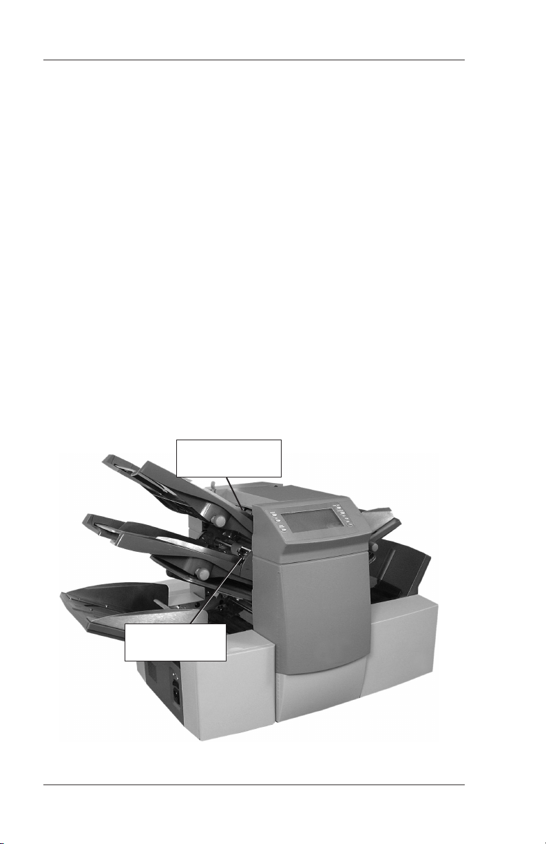
Some models are equipped with OMR (Optical Mark Recognition)
scanning.
An OMR mark is normally a dark solid line on a sheet of light colored
paper that is perpendicular to the direction of paper travel. This line
must be thick and dense enough to trigger the system’s OMR scanner.
The scanner, working with the OMR system software, checks for one
or more different OMR marks on a document as it feeds through the
system. Tracking of these marks enhances mail piece integrity by
assuring that documents that belong together (a set) stay together
throughout the inserting process.
OMR-equipped models have scanning heads located on each of the
sheet feeders.
Instructions for using OMR functions appear in Chapter 3 of this
guide.
Top Sheet
Feeder Scanner
Bottom Sheet
Feeder Scanner
1-4 SV61656 Rev. A
Page 11
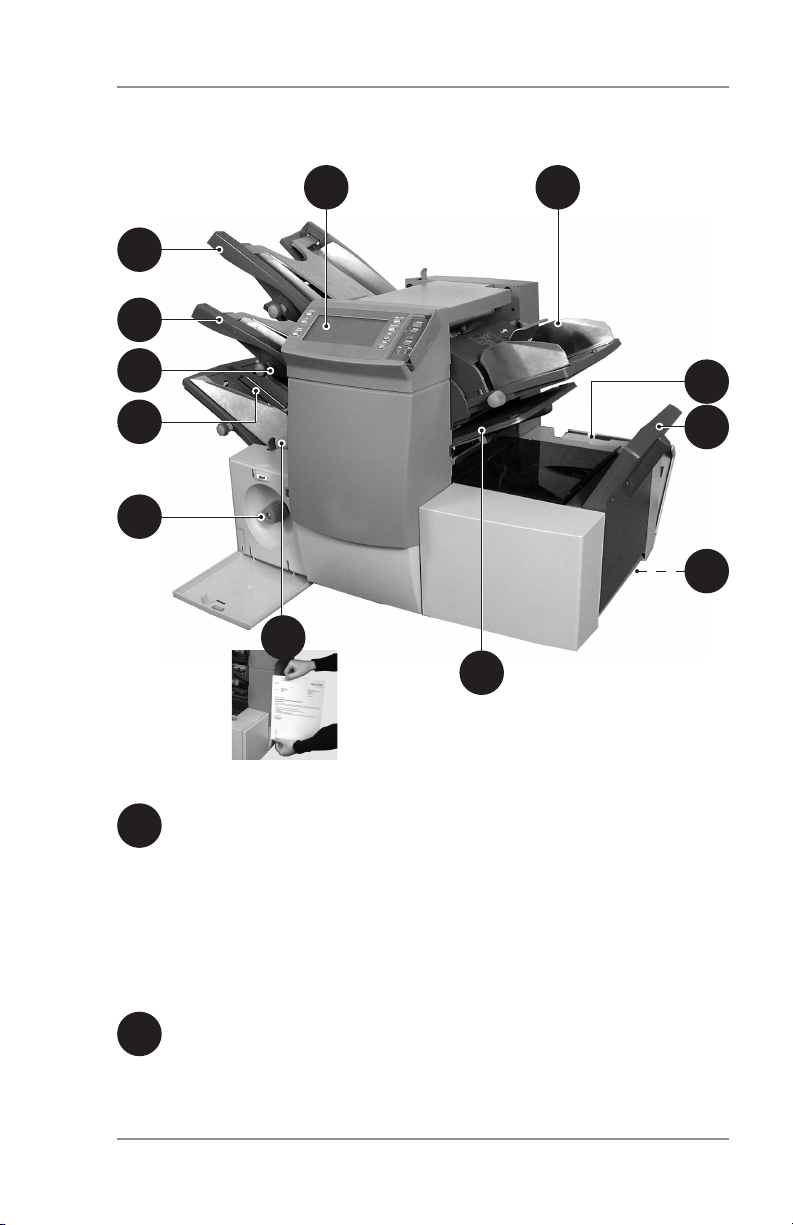
Machine Identification
1
2
Introduction • 1
36
5
9
8
11
4
Sheet Feeder 1 — This feeder is intended for feeding material
1
that requires folding.
In addition, you can set sheet feeder 1 to Manual Feed. In this
mode, you can run stapled sets of up to five sheets. The machine waits for each set to be manually fed into sheet feeder
1 before folding and inserting the set automatically. See the
Specifications section of this guide for full details of the sets
possible.
Sheet Feeder 2 — For feeding material that requires folding.
2
Its functions are similar to sheet feeder 1, but manual feed is
NOT available from this feeder.
10
12
7
1-5SV61656 Rev. A
Page 12
1 • Introduction
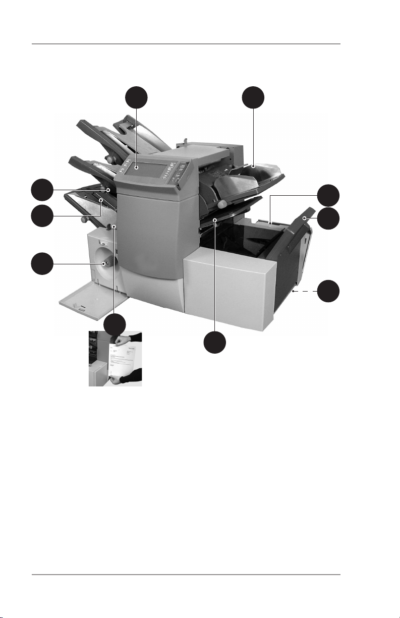
Machine Identification (Continued)
36
5
9
10
12
8
7
11
4
1-6 SV61656 Rev. A
Page 13

Introduction • 1
Insert Feeder — Use this feeder to add additional inserts to
3
your envelope. Material fed from this feeder cannot be folded
by the inserter. However, this feeder is especially suited to
feeding pre-folded or thicker inserts.
4
Fold Plates 1 and 2 — These create the desired fold in
material fed from the sheet feeder(s). The fold plates are auto-
5
matically set from the control panel.
Display/Control Panel — This is where you enter commands
6
and where the machine informs you of its status with the use
of symbols and icons. Each button function is explained on the
following page.
Drop Stacker or Output Device (not illustrated)
7
A fold down stacker is located at the exit from the machine
to collect the finished mail pieces. This unit can be latched
against the machine when not in use. Alternatively, a range of
power stackers are available which offer greater capacity than
the standard drop stacker.
A mailing machine interface can be installed in place of a
stacker. This device automatically transports mail pieces to a
Pitney Bowes mailing machine for postage imprinting.
8
Manual Advance Knob —The manual advance knob is locat-
ed inside an opening cover at the lower center of the machine.
Use it to turn the machine mechanisms by hand to help clear a
material stoppage.
Envelope Feeder — This feeder feeds envelopes into the
9
inserting area where they are filled with material requested
from the other feeder(s).
Sealer Bottle — The sealer bottle is located inside an opening
10
cover at the front right side of the machine. It provides sealing
solution to the envelope sealer.
11
Measuring Scale — The scale is located on the left side
of the machine near the sheet feeders. Use it as an aid in
measuring material and envelopes.
12
Envelope Inverter — This unit transports the envelope into
the stacker face up.
1-7SV61656 Rev. A
Page 14

1 • Introduction
Control Panel
Control Panel Buttons
Default — Press this button to return the machine to its default or
‘standard’ settings. These settings come pre-configured from the
factory but can be modified to suit your needs by a Pitney Bowes
Service Representative.
Job — Press to step through the jobs you’ve programmed into the
machine’s memory. The machine will store up to 20 jobs. See page
2-9 for details of programming jobs.
Reset Counter — Press to reset the item or batch counter.
Clear Deck — Press to jog material through and out of the system.
Use clear deck to clear the machine and make it ready for automatic
operation after a stoppage has occurred.
Trial Piece — Press to run a single test piece so that you can
check machine setup. You MUST run a trial piece before you begin
automatic operation by pressing the Start button. If you’re using
double detection, the machine sets itself automatically as it runs the
trial piece. This envelope will be unsealed and counted as one item.
Start — Starts automatic operation.
Stop — Stops automatic operation at the end of the next cycle.
Delete — Use in setup mode to delete a programmed job from
memory.
Setup — Press to enter the machine setup mode. This mode allows
you to program jobs into memory for instant recall using the Job
button.
Change + – In setup mode, press + or - to select options or set
values of machine settings.
Prev. ◄ ► Next — In setup mode, use these keys to step backward
or forward through the various job settings.
1-8 SV61656 Rev. A
Page 15
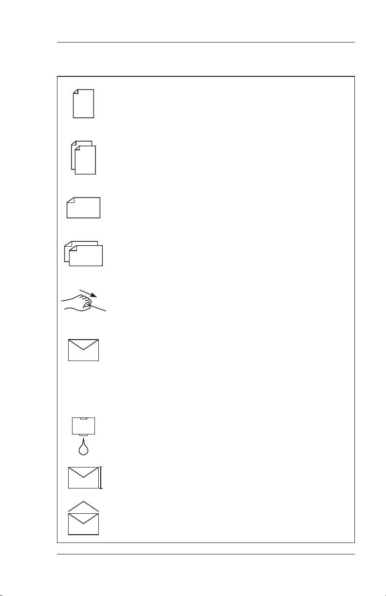
Display Symbols
Used on sheet feeders to signify that the feeder is on
without double detection.
Used on sheet feeders to signify that the feeder is on
with double detection.
Used on insert feeder to signify that the feeder is on
without double detection.
Used on insert feeder to signify that the feeder is on
with double detection.
Used on sheet feeder 1 to signify that the feeder is set
for manual feed.
Introduction • 1
Used on envelope feeder to signify that the feeder is
on.
Indicates the setting (from 1 to 5) of the envelope
stop.
Indicates that the sealer bottle needs refilling.
Indicates the envelope depth.
Indicates that the sealer unit is off (envelopes not
sealed).
1-9SV61656 Rev. A
Page 16
1 • Introduction
!"#
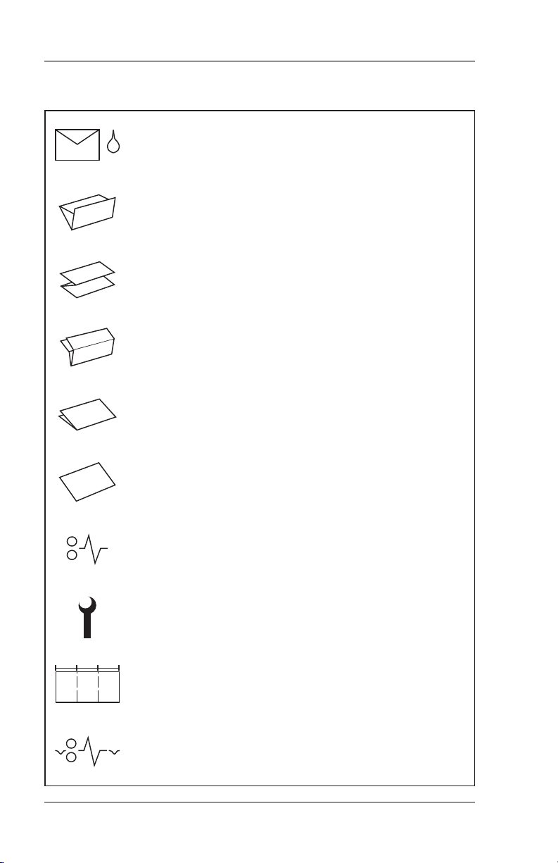
Display Symbols (Continued)
Indicates that the sealer unit is on (automatic envelope sealing).
Indicates a C-fold (letter) fold is selected.
Indicates a Z-fold (accordion) is selected.
Indicates a double fold is selected.
Indicates a single fold is selected.
Indicates a no-fold insert operation.
Indicates a material stoppage. The position of this
symbol in the display indicates where the stoppage
has occurred.
Call for service.
Indicates the paper size, address orientation and
fold(s) set for sheet feeder.
Indicates a material stoppage in a downstream device, such as a power stacker or mailing machine
Interface (MMI).
1-10 SV61656 Rev. A
Page 17
Operation • 2
About this Chapter
This chapter explains operation of the machine, assuming the job
you want to run is already programmed into the system.
If you haven’t programmed the job, please go to Programming Jobs
on page 2-9.
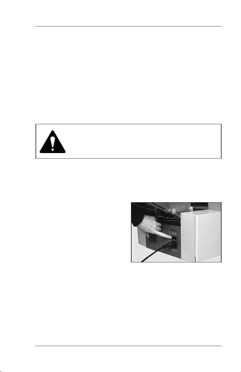
Connecting Power
IMPORTANT! Read the safety information on
pages 1-1 and 1-2 of this guide before you
connect the machine.
Connect the power cord to the socket on the left side of the machine.
Plug the power cord into a suitable power outlet. Make sure the power outlet is near the machine and
is easily accessible.
Turn the power switch ON.
2-1SV61656 Rev. A
Page 18
2 • Operation
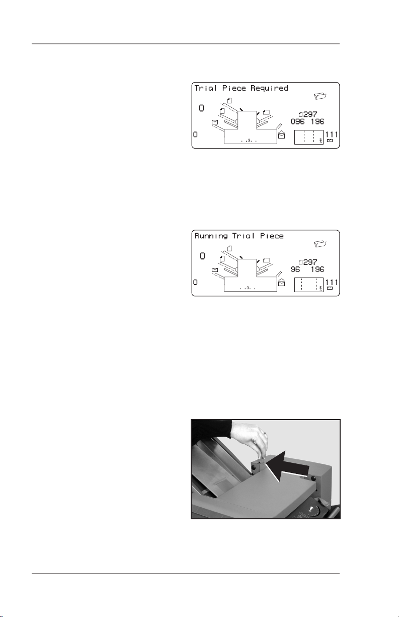
Select a Job
When the machine is turned ON,
the display shows the last job run
and “Trial Piece Required”.
Press the Job button until the job
you require is displayed, or press
Default if you want to run the
machine with your standard job
settings.
Note: Only a Pitney Bowes Service Representative can modify the
default job.
If you have material loaded, press
Trial Piece. The machine sets
itself and runs a test piece for you
to check.
If you don’t have material loaded,
do this now, then return to this
section. Loading feeders and related instructions are covered on pages 2-4 to 2-7.
Note:
You may have selected a manual feed job where sheet feeder 1 is
set for manual feed of collated sets. If this is the case, DO NOT load
the sheet feeder; you will feed collated sets one at a time by hand as
required by the machine.
For manual feed jobs, pull back
the lever as shown in the illustration, right. This opens the feed
mechanism, making it ready for
manual feed operation.
Remember to return this lever to
its normal position when you use
the feeder for automatic operation.
2-2 SV61656 Rev. A
Page 19

Operation • 2
Run a Trial Piece
Once material is in place, press Trial Piece so you can check that
setup is correct.
You can make minor changes to the job settings at this stage if the
trial piece needs fine tuning. Enter setup as described on page
2-9, then use the Prev (◄), Next (►) and Change (+/-) buttons as
required to modify job settings. When you’ve made the necessary
changes, press Setup again to return to run mode. The inserter
saves the job with the new settings.
Notes:
1. When using linked feeding,* load both sheet feeders before running a trial piece.
2. If you load material during a run which seems to have different
characteristics (weight, color shade, etc.), or if you have any
problems with double detection, run another trial piece. This
forces the machine to recalibrate the double detect function for
the new material in case the batches vary slightly.
Start Machine Operation
Press Start to begin automatic operation.
The machine runs until either material runs out or you press the
Stop button.
Note: If the machine is set for linked feeding, the display shows:
1 > 2 > 1
This confirms that feeding will automatically switch between
sheet feeders. See page 2-13 for more details.
* “Linking” is a method of using two feeders such that when one feeder
runs out of material, the next “linked” feeder automatically starts feeding.
Linking feeders allows you to process a higher volume of material before
reloading. Linked feeders are sometimes referred to as “cascading”
feeders.
2-3SV61656 Rev. A
Page 20
2 • Operation
Setting the Sheet Feeders
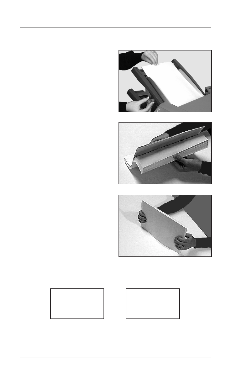
1. Adjust the side guides to the
width of the material you’re
running, then back-off a
quarter turn on the side guide
control. This sets the correct clearance between the
guides and the material.
2. Take the stack of paper and
aerate it to ensure that individual sheets are not stuck
together.
3. Jog the stack back into alignment. The sheet feeders accept the paper stack aligned
in a manner similar to that
of a photocopier paper cassette.
4. The display shows the correct orientation of the paper.
FACE UP
HEAD FIRST
2-4 SV61656 Rev. A
ABC
ABC
FACE DOWN
FEET FIRST
Page 21

Operation • 2
5. Place the paper stack onto
the feed deck. Allow the deck
to move down and the top of
the paper stack to slide under the feed roller.
Note:
When using both sheet feeders
for an accordion fold job, always
use sheet feeder 2 for the prime (address-bearing) document.
2-5SV61656 Rev. A
Page 22
2 • Operation
Setting the Envelope Feeder
The envelope feeder feeds the outer envelope for the inserting job
you’re running.
1. Adjust the side guides to the
width of the envelopes you’re
running, then back off half a
turn on the side guide control.
This sets the correct clearance between the guides and
the envelopes.
2. Aerate (fan) the stack of envelopes you’re running.
3. Place envelopes on the feed
deck with their flaps up and
trailing.
IMPORTANT ! Check that
lead edge of the first envelope is under the front feed
roller and that the stack of
envelopes is shingled on the
deck as shown.
Let the wedge slide down
behind the stack so that the
envelopes are supported.
Setting the Insert Feeder
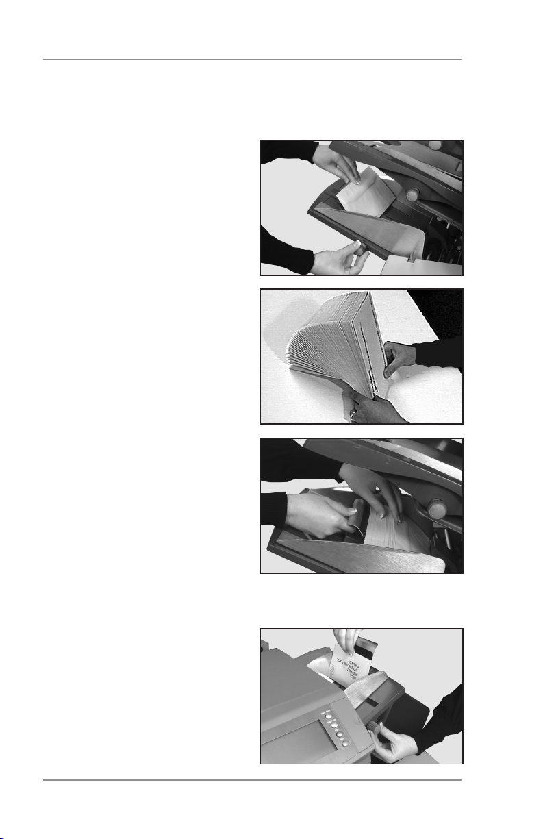
1. Adjust the side guides to the
width of the material being
fed, then back off a quarter turn on the side guide
control. This sets the correct clearance between the
guides and the material.
2-6 SV61656 Rev. A
Page 23
Operation • 2
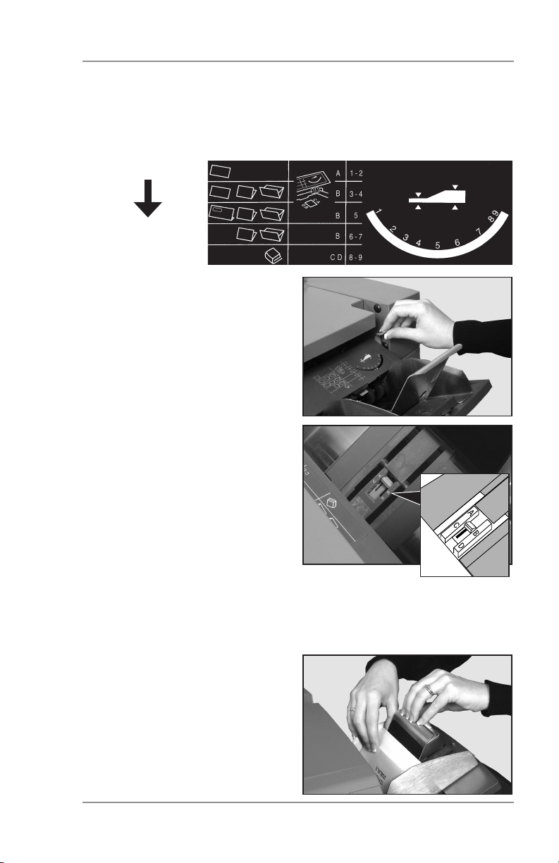
2. Refer to the label located on the insert feeder. Compare your
insert with the diagram. Read off the settings for the insert feeder
blue lever (numbers 1 to 9) and the separator shield (letters A to
D).
Thin Material
Thicker Material
Thick Inserts,
Booklets, etc.
3. Set the blue lever to the
number required.
4. Set the separator shield to
the letter required.
5. Fan the inserts and place
them onto the feed deck.
Loading orientation can vary
depending on the actual
inserts you’re running. For
many applications we suggest the following:
• Slip — Face up, bottom edge first
• Reply Envelope — Face up, top edge first
• Pre-Folded — Face up, closed edge first
• Booklet — Face up,
bound edge first
Let the wedge slide down
behind the stack so that the
inserts are supported.
2-7SV61656 Rev. A
Page 24
2 • Operation
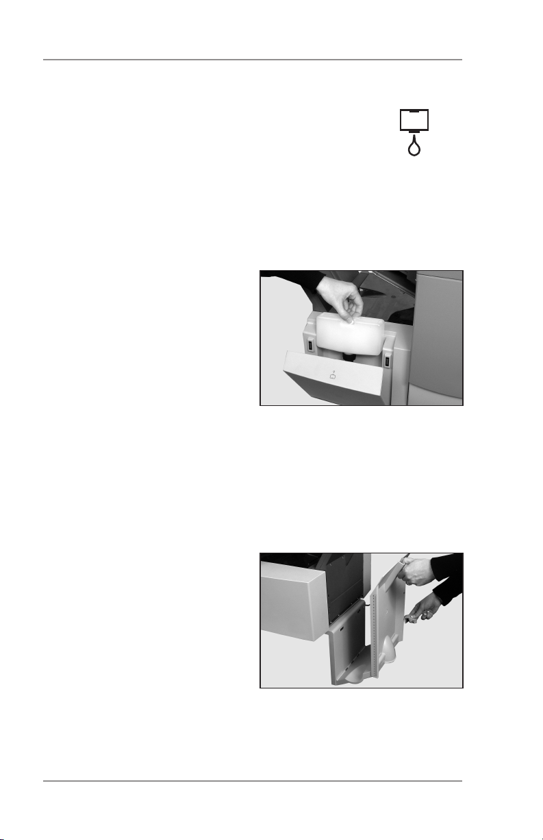
Filling the Sealer
When the sealer unit needs refilling, the Add Sealing
Solution symbol flashes in the display.
Add E-Z Seal® or water in the following way:
Note: We recommend E-Z Seal® to minimize scale buildup
and the growth of algae.
Hinge open the sealer bottle cover located at the rear right hand
side of the machine. Remove the
bottle.
Fill the bottle up to the level indicated.
Put the sealer bottle back in position and close the cover.
Note: If the sealer unit has emptied completely, allow enough time
for the solution to soak through the sealer mechanism. This
helps assure good seals.
Adjusting the Stacker
Adjust the drop stacker to suit the
material you’re running.
Lift the lever at the rear of the
stacker and adjust the stacker
to one of the preset positions.
Lower the lever to lock the stacker into position.
When not in use, you can raise
and latch the stacker vertically against the exit area of the machine
as shown in the photo above.
2-8 SV61656 Rev. A
Page 25
Operation • 2
Programming Jobs
You can program your machine with jobs that you can recall at the
touch of a button.
All models have 20 operator-programmable jobs plus one default job
that your Pitney Bowes Service Representative normally sets.
Creating a New Job
This section takes you step-by-step through the process of setting
up a new job and saving it in memory.
Throughout the programming sequence, an asterisk (*) will flash on
the display next to the item you’re setting. Use the Prev (◄) and
Next (►) buttons to step forward or backward through the available
settings. Once an option displays, use the Change (+/-) buttons to
select the option or value you want.
Note: Your machine may be equipped with OMR (Optical Mark
Recognition) scanning, depending on the model you pur-
chased. To program an OMR job, go to page 3-10 of this
guide. To program a non-OMR job, continue by entering the
Setup Mode…
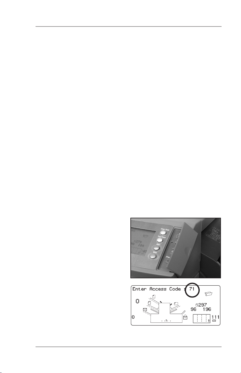
Entering the Setup Mode
Open the hinged cover to the
right of the display. This exposes
the setup buttons.
Press Setup. The indicator lights
and the machine asks for an access code. This code prevents
the machine’s settings being
changed by unauthorized personnel.
Use the Change (+/-) buttons to
select the access code 71.
Press Next (►) to advance to the
next setting…
2-9SV61656 Rev. A
Page 26

2 • Operation
Choosing the New Job Number
The machine asks for the job
number you wish the new settings
to be stored under.
Use the Change (+/-) buttons to
display the job number you want.
Notes:
• If you use an existing job
number, the old settings will be overwritten by the new settings
you are about to make.
• If you want to find a currently unused job number, press Change
(+/-) until you see a job where the display shows no symbols
alongside the feeders or in the fold setup area. This means the
job number is currently unused.
Press Next (►) to advance to the next setting…
OMR
On models equipped with OMR ONLY, the machine will ask you to
select the OMR mode. For a non-OMR job, use Change (+/-) to select OMR off (if you wish to program an OMR job, see page 3-10).
Press Next (►) to advance to the next setting…
2-10 SV61656 Rev. A
Page 27
Operation • 2
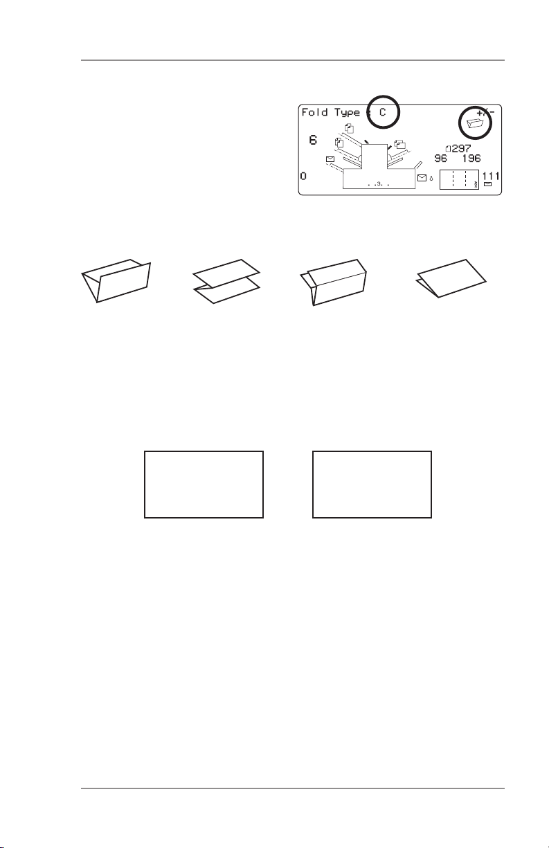
Fold Type
Select the type of fold. See the
illustrations below.
Press Change (+/-) until you see
the option you want:
C (Letter) Z (Accordion) Double Single
Note: For accumulation jobs, DO NOT manually change the
fold length dimensions at the “Fold A” and “Fold B” settings
(pages 2-17 and 2-18). The machine sets these automati
cally.
When you’ve selected the fold type, the display shows the correct
orientation for loading paper into the feeders:
FACE UP
HEAD FIRST
ABC
ABC
FACE DOWN
FEET FIRST
When you’ve set the fold type as required, press Next (►) to advance to the next setting…
2-11SV61656 Rev. A
Page 28

2 • Operation
Setting the Accumulation Function
Accumulation, if selected, allows
multiple sheets to be fed from the
same feeder into the envelope.
Press Change (+/-) until you see
the option you want.
Accumulation: OFF
Accumulation is turned off for this job.
1- and 2-station machines...
Accumulation: ON
Accumulation is turned on for this job.
3-station machines...
Accumulation From Main
Accumulation is turned on with sheets feeding from the main
feeder. This feeder normally contains the address sheet.
Accumulation From Suppl
Accumulation is turned on with sheets feeding from the
Supplementary feeder (that is, one address sheet from the
main feeder followed by multiple sheets from the supplementary feeder.
Press Next (►) to advance to the next setting…
Accumulation = (2 to 10)
Select how many pages you want to feed into each envelope
using Change (+/-).
Important: The number of sheets the machine can accumulate
is limited by machine specifications. Exceeding this
limit can cause the machine to malfunction. See
page 4-14 for details.
2-12 SV61656 Rev. A
Page 29
Operation • 2
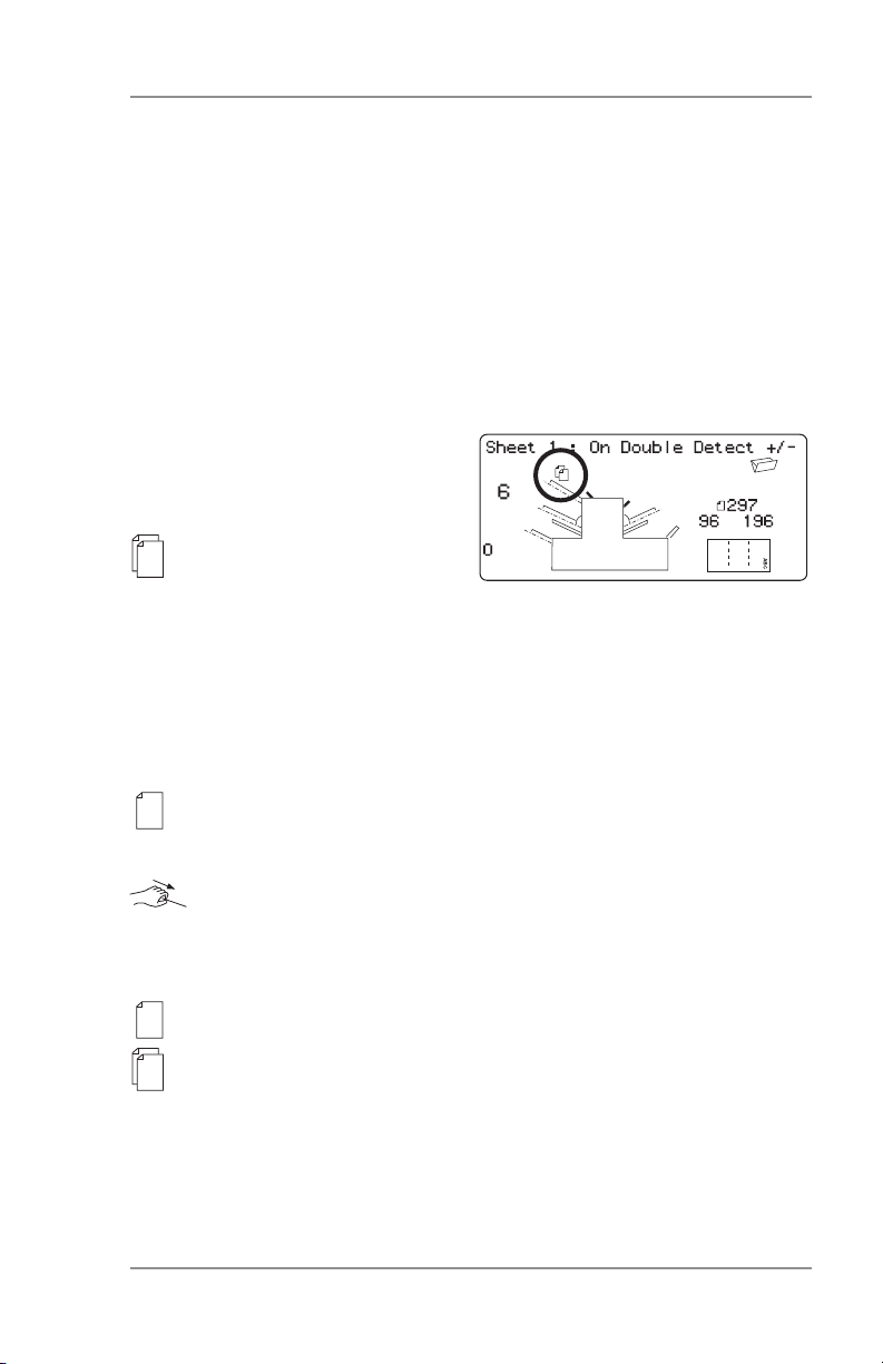
Setting the First/Main Sheet Feeder
The machine automatically selects the first feeder to set, depending
on the fold type selected.
Note: If you’re collating different sheets using both sheet feeders,
you must load the prime (addressed) document into sheet
feeder 1 for C and Double folds, and into sheet feeder 2
for Z- or single folds. If you’re using a single sheet only, you
may use either sheet feeder or you can use both by choos
ing the linked feeder option described below.
Press Change (+/-) until you see
the option you want:
On Double Detect
Feeder on with the
double detector operating. (The double detector stops the machine if two or more
sheets feed simultaneously from the feeder).
Off
Feeder turned off for this job.
On
Feeder on without the double detector.
Manual Feed
Allows you to manually feed collated sets (only available on
sheet feeder 1; also see notes on following page).
Linked: On
Linked: On Double Detect
These functions are available only on the three-station ma-
chine. Feed will initially be from the first sheet feeder. When
the feeder is empty, the machine automatically switches to
feeding from the second sheet feeder.
Load both feeders before running a trial piece. This is neces-
sary because each feeder will feed a trial piece.
continued...
2-13SV61656 Rev. A
Page 30
2 • Operation
Notes about manual feed:
1. The manual feed setting allows you to run stapled sets of up
to five sheets to a maximum of 100 lbs. (400g/m2 per set). The
maximum compressed thickness of the set after folding must
not exceed 0.08 inches (2mm). The machine will wait for manual
insertion of each set into sheet feeder 1, after which it will fold
and insert the set automatically.
2. When running manual feed mode, sheet feeder 2 becomes inoperable.
When the first sheet feeder is set as required, press Next (►) to advance to the next setting…
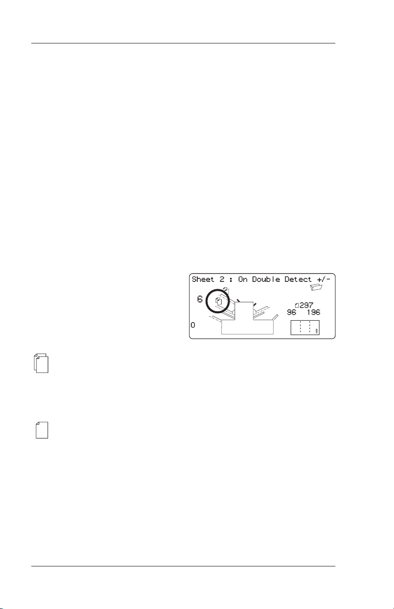
Setting the Second/Supplementary Sheet Feeder
Select whether you want to use
the second sheet feeder.
Press Change (+/-) until you see
the option you want:
On Double Detect
Feeder on with the double detector operating. (The double
detector stops the machine if two or more sheets feed simultaneously from the feeder).
On
Feeder on without the double detector.
Off
Feeder turned off for this job.
When the second sheet feeder is set as required, press Next (►) to
go to the next setting…
2-14 SV61656 Rev. A
Page 31

Operation • 2
Setting Insert Feeder
Select whether you want to use
the insert feeder and, if so, how it
will be used.
Press Change (+/-) until you see
the option you want:
On Double Detect
Feeder on with the double detector operating. (The double
detector stops the machine if two or more inserts feed simultaneously from the feeder).
On
Feeder on without the double detector.
Off
Feeder turned off for this job.
When the insert feeder is set as required, press Next (►) to advance to the next setting…
Mode
The machine needs to know if the job requires inserting into an envelope or if it is a fold-only job.
Press Change (+/-) to switch between the options:
Insertion Mode
Activates the envelope feeder for a normal inserting job.
Fold-Only Mode
Turns the envelope feeder off and makes the machine act as
a folding machine.
When the mode is set, press Next (►) to advance to the next setting…
2-15SV61656 Rev. A
Page 32

2 • Operation
Sealer
This setting only appears if an insertion mode has been selected.
Select whether you want to seal envelopes or not.
Press Change (+/-) to switch the option on or off:
On
Turns the sealer unit on for automatic sealing of envelopes.
Make sure the sealer water bottle is full of E-Z Seal® or water (see page 2-10).
Off
Turns the sealer unit off. Envelopes will be ejected unsealed.
When the sealer is set as required, press Next (►) to advance to the
next setting…
If you have selected either of the sheet feeders, the next setting offered will be paper length. However, if you are using the insert feeder
only, folding is not possible and the display will advance directly to
the envelopedepth setting explained on page 2-18.
2-16 SV61656 Rev. A
Page 33

Operation • 2
Paper Length
Select the paper length.
Use the scale on the edge of the
front cover.
Quick reference:
A4 paper length: 297mm
US Letter length: 11" (279mm)
Press Change (+/-) until the
length of your paper (in millimeters) displays.
When the paper length is correct, press Next (►) to go to the next
setting…
Fold A
Select the size of the first fold required.
Depending on the settings previously made for fold type and
paper length, the machine will
suggest the correct dimension for
the first fold. Most times, therefore, this setting will not require
change.
If you want to change the standard setting, press Change (+/-) until the length of the fold required is displayed. The symbol | –––– |
shows the fold panel you are adjusting.
The machine will automatically limit your choices to what is physically possible within the machine specifications. (As you change the
length of Fold A, you’ll see the dimension of Fold B automatically
changing to keep within paper Length and machine specifications.)
When the setting is correct, press Next (►) to advance to the next
setting…
2-17SV61656 Rev. A
Page 34

2 • Operation
Fold B
Select the size of the second fold
required.
In a manner similar to that of fold
A, the machine suggests the correct dimension for the fold.
If you want to change the standard setting, press Change (+/-) until the length of fold required displays. The symbol | –––– | shows the fold panel you’re adjusting.
When the setting is correct, press Next (►) to advance to the next
setting…
If you’re programming an inserting job, the envelope depth setting
now appears. If you’re programming a fold-only job, the display goes
straight to the Confirming the Job Setup section explained on page
2-20.
Envelope Depth
Select the depth of your envelopes (in millimeters).
Again, you can use the scale on
the front cover to measure the
depth of your envelopes.
Press Change (+/-) until the correct dimension is displayed.
When you’ve set envelope depth as required, press Next (►) to go
to the next setting…
2-18 SV61656 Rev. A
Page 35

Operation • 2
Envelope Stop
Select the position of the machine’s envelope stop.
The stop has five positions numbered 1 to 5. Setting 3 is the
standard setting for normal weight
paper with standard folds. A thinner/lighter insert will require a
lower setting and thicker/heavier insert a higher setting.
Press Change (+/-) until the setting you want is displayed.
When the envelope stop is set as required, press Next (►) to advance to the next set
Batch Counter
The batch counter allows you to automatically process pre-defined
batches of finished mail pieces. When the batch is complete, the
machine stops automatically. Press Start to begin processing of the
next batch.
If batch counter is not selected, the display counter simply counts
the number of items processed until you press Reset Counter.
Press Change (+/-) to switch
Batch Mode On or Off.
When the setting is correct,
press Next (►).
If the batch counter is turned on,
the machine will now request
the batch quantity. The default
quantity is 50, but you may select
any value up to 999 using the
Change (+/-) buttons.
When the setting is correct, press Next (►).
2-19SV61656 Rev. A
Page 36

2 • Operation
Confirming the Job Setup
Job setup is now complete. The
display will show the complete job
setup for you to confirm.
If you see a setting that’s incorrect, use the Prev (◄) button to backtrack to the setting and correct it.
When you’re satisfied with the job setup, press the Setup button.
The machine will save the job in its memory and reset to the new job.
When this is complete, the display
will show the new job with the
message “Trial Piece Required”.
Job settings are retained by the
machine even with power disconnected until you change or delete
them as described on page 2-22.
2-20 SV61656 Rev. A
Page 37

Operation • 2
Testing the Job
Load material and press Trial Piece so that you can check if the
setup is correct.
You can make minor changes to the job settings at this stage if the
trial piece needs fine tuning. Press Setup, then use the Prev (◄),
Next (►) and Change (+/-) buttons as required to modify job settings. The chart below will help you fine tune your fold settings.
FOLD TYPE ADDRESS TOO LOW ADDRESS TOO HIGH
C - Letter Fold Decrease Fold A Increase Fold A and
increase Fold B by
the same amount
Z - Accordion Increase Fold A Decrease Fold A a
Fold increase Fold B by
the same amount
Single Fold Increase Fold A Decrease Fold A
Double Fold Decrease Fold A Increase Fold A
We suggest that you change folds by 0.20 inches (5mm) each time
and run a new trial piece run to test the settings.
When you’ve made the necessary changes, press Setup again to
return to run mode. The machine will save the job with the new settings.
2-21SV61656 Rev. A
Page 38

2 • Operation
Changing an Existing Job
To change an existing job:
1. Enter the setup mode as described on page 2-9.
2. Use the Change (+/-) buttons to display the job you wish to edit.
3. Use the Prev (◄) and Next (►) buttons to display the setting(s)
you wish to change.
4. Use the Change (+/-) buttons to change the options/dimensions
you wish to amend.
5. Press the Setup button to leave the setup mode and save the
changes.
Deleting a Job
To erase an existing job from memory:
1. Enter the setup mode as described on page 2-9.
2. Use the Change (+/-) buttons to display the job you wish to delete.
3. Press the Delete button. The display reads “Press again to confirm”. Press Delete again. The display will briefly read ‘Deleting
Job’ as the job is erased.
4. Press the Setup button to leave setup mode.
2-22 SV61656 Rev. A
Page 39

OMR • 3
OMR Availability
Your machine may be equipped with Optical Mark Recognition
(OMR) scanning, depending on the model you purchased.
All models have 20 Operator programmable jobs plus one default job
your Pitney Bowes Service Representative normally sets.
What is OMR?
An OMR mark is normally a dark solid line on a sheet of light colored
paper that is perpendicular to the direction of paper travel. This line must be
sufficiently thick and dense to trigger the
OMR scanner on the system.
The OMR scanner, working with the
OMR system software, checks for one
or more different OMR marks on a document as it feeds through the system. The
tracking of these marks enhances mail
piece integrity by assuring that sheets
which belong together actually stay together throughout the entire inserting
process.
Use the Prev (◄) and Next (►) buttons to step forward or backward through the settings available. Once the item displays, use the
Change (+/-) buttons to select the option you want.
Typical
OMR marks
A Brief Overview of OMR on Your Machine
One sheet feeder holds sheets with OMR marks:
• Sheet feeder 1 for C-fold and double fold applications
• Sheet feeder 2 for Z-fold and single fold applications
The sheet feeder holding the sheets with OMR marks can feed mul-
tiple sheets per envelope.
The sheet feeder not holding OMR sheets can hold supplementary
sheets that you can place under the selective control of the OMR
sheets.
3-1SV61656 Rev.A
Page 40

3 • OMR
You can also set up the insert feeder to be under the selective
control of the OMR sheets. As a result, you can use OMR to fill an
envelope with a variable number of sheets from one feeder, with or
without a supplementary sheet and an insert.
A supplementary sheet and folded insert will be nested with the
first sheet in the envelope. Because OMR allows each envelope to
contain tailored contents, the last sheet in the envelope will include
address information for use with windowed envelopes to ensure that
each set of sheets is addressed to the correct recipient.
OMR on this system uses extensive error checking. This means
insertion accuracy is very high: the probability of the wrong set of
sheets being inserted into an envelope is low.
Levels of OMR on the System
Basic OMR enables you to collate multi-page documents that vary
in number of sheets. It allows you to vary the number of pages per
envelope in a run from one envelope to another through the use of
OMR marks. The machine will fold each OMR sheet separately and
insert it into an envelope, starting with the last sheet of the set and
adding each folded sheet in turn until the address sheet has been
inserted. The machine will then eject the envelope after sealing (if
selected).
Enhanced OMR allows you to stop feeding sheets at selected points
in a run and/or to select whether the other feeders are used. It also
provides a higher level of mail piece integrity so that sensitive documents are not sent to the wrong customer.
OMR Mark Positions
To enable the inserter’s OMR scanners to read the printed OMR
marks, the marks MUST be positioned within a defined range of positions on the page.
Standard OMR positions are given in the diagram on page 3-4.
Offset OMR positions allow the marks to be positioned further down
the page. Specifications are given in the diagram on page 3-5. To
use Offset OMR, you must select one of the offset OMR functions
when programming the OMR job. See page 3-10 for full details.
3-2 SV61656 Rev. A
Page 41

OMR • 3
OMR Specifications
The mark must be a solid black line between 1pt and 2pts thick
(0.014 inch [0.35mm] to 0.027 inch [0.7mm]) and at least 0.393 inch
(10mm) wide.
Each mark position must be evenly spaced and at least 0.118 inch
(3mm) apart.
An area around the marks should be kept clear from print and any
other marks that might be read by the scanner in error. This area is
called the clear zone.
There should be no print on the opposing face of the sheet immediately behind the clear zone.
Clear Zone
0.118 inch (3mm)
minimum pitch
1pt to 2pt
0.014 inch (0.35mm)
to
0.027 inch (0.7mm)
thick
0.078 inch
(2mm)
minimum
0.393 inches
(10mm)
minimum
See diagrams on
pages 3-4 and 3-5
1.65 inches (42mm)
maximum
See diagrams on
pages 3-4 and 3-5
0.078 inch
(2mm) minimum
Note: Diagram is not to scale
3-3SV61656 Rev.A
Page 42

3 • OMR
Standard OMR Positions
54mm
min
96mm
max
115mm
min
Double Fold)
*
20mm
min
Clear Zone
20mm x 115mm min
Feed
Direction
for Top
Scanning
(C- and
Clear Zone
20mm x 100mm min
20mm
min
Vertically center group
within area indicated
*
Feed Direction for
Bottom Scanning
(Z- and Single Fold)
Position OMR marks as follows:
C-Fold and Double Fold: Top scanning, top left corner
Z-Fold and Single Fold: Bottom scanning, bottom right corner
3-4 SV61656 Rev. A
100mm
min
69mm
Note: Diagram not to scale
max
*
27mm
min
Page 43

Offset OMR Positions
OMR • 3
95mm
max
20mm
min
125mm
min
65mm
min
Feed
Direction for
Top Scanning
(C- and
Double Fold)
Bench Mark
Feed Direction for
Bottom Scanning
(Z- and Single Fold)
20mm
min
40mm
min
65mm
min
115mm
min
80mm
max
Position OMR marks as follows:
C-Fold and Double Fold: Top scanning, left margin
Z-Fold and Single Fold: Bottom scanning, right margin
Note: Diagram is not to scale
3-5SV61656 Rev.A
Page 44

3 • OMR
OMR Marks Available
This section gives brief descriptions of the OMR marks that can or
must be allocated to an OMR Code.
Note: Some marks within this section are available as added
features which expand OMR capability. Contact
your local Pitney Bowes office for details. OMR features
will vary, depending on the options you purchased.
Benchmark
This is a mandatory mark. It must be the first mark of the code and
will appear on every page within the set.
Safety
This is a mandatory mark that improves the integrity of your mail
piece. It is automatically placed immediately after the benchmark.
End-of-Collation (EOC)
This mark indicates that it is the last sheet fed within the collation/set
(the address sheet).
Your system operates on the absence of this mark, that is, the action
will take place if the mark is NOT read by the scanner. It is therefore
indicated on the OMR code as Not EOC.
Beginning-of-Collation (BOC)
This mark indicates that it is the first sheet fed within the collation/set.
Your system operates on the absence of this mark, that is, the action
will take place if the mark is NOT read by the scanner. It is therefore
indicated on the OMR code as Not BOC.
Parity
This mark is a security feature, that when printed, always makes the
number of marks total an even number. If any one of the marks within
the code is missed during scanning, the machine will stop, allowing
the operator to correct the error.
3-6 SV61656 Rev. A
Page 45

OMR • 3
Retiming Mark
This mark is mandatory in each group of OMR marks making up
the code (see later in this section for an explanation of OMR mark
grouping).
It allows the machine to recalibrate for accurate scanning. Retiming
marks count in the parity calculation.
Select Feed (SF1, SF2)
These marks are used to control the feed of material from the feeder
holding the supplementary sheets/inserts on a set-by-set basis.
Therefore you cannot use select feed on a single station machine.
Select Feed 1 marks are used in the primary sheet feeder to select
material from the supplementary sheet feeder. For C- and double
folds, the primary feeder is sheet feeder 1. For Z- and single folds,
the primary feeder is sheet feeder 2.
Select Feed 2 marks are used in the primary sheet feeder to select
material from the Insert feeder. For C- and double folds, the primary
feeder is sheet feeder 1. For Z- and single folds, the primary feeder
is sheet feeder 2.
Auto Batch
This mark identifies the last set of a batch, when the batch function
is in use. It must be printed on all sheets of the OMR set that requests this function.
Wrap Around Sequence (WAS1, WAS2, WAS3)
This is a numbering system which uses sequential binary coding. If
a page is missing or the set goes out of sequential order, the system
will stop processing and declare an error.
Three wrap around sequence marks are used within the code. The
use of three binary digits allows a decimal count of 0 to 7. Pages
will be numbered from 0 up to 7 and then back to 0 on a continuous
cycle throughout the print run.
3-7SV61656 Rev.A
Page 46

3 • OMR
OMR Mark Grouping
Each OMR code begins with two fixed marks at the end nearest to
the sensor (benchmark and safety mark). These are followed by one,
two, or three groups of marks where each group comprises three
data marks followed by a fixed mark. Each data mark is present or
absent as required to reflect the function desired. Each code must
end with a retiming mark.
Basic OMR mode uses only Group 1.
Enhanced OMR mode uses Group 1 plus Group 2 and/or Group 3,
as needed for a particular job.
C-Fold and Double Fold Jobs
Place marks in the upper left corner of the sheet. Print marks in topto-bottom order:
Feed Direction
Benchmark (fixed)
Group 1
(Mandatory)
Group 2
Group 3
Safety (fixed)
Not EOC
Not BOC
Parity
Retiming (fixed)
Select Feed 1
Select Feed 2
Auto Batch
Retiming (fixed if this group is in use)
Wrap Around Sequence 3 (WAS3)
Wrap Around Sequence 2 (WAS2)
Wrap Around Sequence 1 (WAS1)
Retiming (fixed if this group is in use)
Print sheets in reverse collation order. In this way, the last sheet
processed in each set is the address sheet and the first sheet processed is the last of each set.
3-8 SV61656 Rev. A
Page 47

OMR • 3
Z-Fold and Single Fold Jobs
Place marks in the lower right corner of the sheet. Print the marks in
bottom-to-top order:
Retiming (fixed if this group is in use)
Group 3
Group 2
Group 1
(Mandatory)
Wrap Around Sequence 1 (WAS1)
Wrap Around Sequence 2 (WAS2)
Wrap Around Sequence 3 (WAS3)
Retiming (fixed if this group is in use)
Auto Batch
Select Feed 2
Select Feed 1
Retiming (fixed)
Parity
Not BOC
Not EOC
Safety (fixed)
Benchmark (fixed)
Feed Direction
Print sheets in normal collation order. In this way, the first sheet processed in each set is the address sheet and the last sheet processed
is the last of each set.
3-9SV61656 Rev.A
Page 48

3 • OMR
Programming an OMR Job
Entering the Setup Mode
Open the hinged cover to the
right of the display. This exposes
the setup buttons.
Press Setup. The indicator lights
and the machine asks for an access code. This code prevents
unauthorized personnel from
changing the machine’s settings.
Use the Change (+/-) buttons to
select the access code 71.
Press Next (►) to advance to the
next setting…
Choosing the New Job Number
The machine asks for the job
number you wish the new settings
to be stored under.
Use the Change (+/-) buttons to
display the job number you want.
Notes:
• If you use an existing job
number, the old settings will
be overwritten by the new settings you are about to make.
• If you want to find a currently
unused job number, press
Change (+/-) until you see a
job where the display shows no symbols alongside the feeders
or in the fold setup area. This means the job number is currently
unused.
Press Next (►) to advance to the next setting…
3-10 SV61656 Rev. A
Page 49

OMR • 3
Selecting the OMR Functions
Press Change (+/-) until you see the option you want. Note that the
options shown will depend on the OMR functionality that your machine has. Details of standard and offset OMR positioning appear on
pages 3-4 and 3-5.
OMR off
OMR is turned off for this job.
OMR on
OMR is turned on (Basic Scanning) for this job with standard
OMR mark positioning.
OMR + Sequence
Basic scanning + Wrap Around Sequence scanning for this job
with standard OMR mark positioning.
OMR + Select feed
Basic scanning + Select Feed/Autobatch scanning for this job
with standard OMR mark positioning.
OMR + Select feed + Sequence
Basic scanning + Select Feed/Autobatch + Wrap Around
Sequence scanning for this job with standard OMR mark positioning.
OMR Offset on
OMR is turned on (Basic Scanning) for this job with offset OMR
mark positioning.
OMR Offset + Sequence
Basic scanning + Wrap Around Sequence scanning for this job
with offset OMR mark positioning.
OMR Offset + Select feed
Basic scanning + Select Feed/Autobatch scanning for this job
with offset OMR mark positioning.
OMR Offset + SF + Sequence
Basic scanning + Select Feed/Autobatch + Wrap Around
Sequence scanning for this job with offset OMR mark positioning.
continued...
3-11SV61656 Rev.A
Page 50

3 • OMR
Notes:
OMR (Basic scanning) offers the following scanning
functions: Benchmark
Safety
End-of-Collation absent
Beginning-of-Collation absent
Parity
Retime
Select feed/autobatch offers the following scanning
functions: Select feed 1
Select feed 2
Autobatch
Retime
Sequence offers:
Three wrap-around page sequence marks
Retime
The maximum pages per set that can be fed from either sheet feeder
1 or 2 when using the OMR function must fall within the limits detailed on page 4-14 of this guide.
Press Next (►) to advance to the next setting…
3-12 SV61656 Rev. A
Page 51

OMR • 3
Fold Type
Select the type of fold.
Press Change (+/-) until you see
the option you want:
Note: For OMR scanning jobs, DO NOT manually change the
fold length dimensions for Fold A and Fold B. These are set
automatically by the machine.
C — Letter Z — Accordion Double Single
When you select either a C-fold or a double fold, the machine automatically selects top sheet feeder 1 as the scanning feeder. If you
select either a Z- fold or a single fold, the machine automatically selects the bottom sheet feeder 2 as the scanning feeder.
The display shows the correct orientation for loading paper into the
feeders:
FACE UP
HEAD FIRST
ABC
ABC
FACE DOWN
FEET FIRST
When the fold type is set as required, press Next (►) to advance to
the next setting…
3-13SV61656 Rev.A
Page 52

3 • OMR
Setting the Main (Scanning) Sheet Feeder
Press Change (+/-) until you see
the option you want:
On Double Detect
Feeder is on with the double detector operating. (The double
detector stops the machine if two or more sheets feed simultaneously from the feeder.)
On
Feeder on without the double detector.
When the Sheet Feeder is set as required, press Next (►) to advance to the next setting…
3-14 SV61656 Rev. A
Page 53

OMR • 3
Setting Select/Supplementary Feeders
Press Change (+/-) until you see
the option you want:
If sheet feeder 1 is the main/
scanning feeder, you can program sheet feeder 2 and/or the
insert feeder for normal (one per
envelope) feeding or select feeding.
If sheet feeder 2 is the main/scanning feeder, you can program sheet
feeder 1 and/or the insert feeder for normal (one per envelope) feeding or select feeding.
Select feed allows the machine to feed one piece selectively from
either feeder per envelope.
On Double Detect
Feeder on with the double detector operating, without select
feed. (The double detector stops the machine if two or more
sheets feed simultaneously from the feeder.)
On SF Double Detect
Select feeder on with the double detector operating. (The
double detector stops the machine if two or more sheets
feed simultaneously from the feeder.)
On SF
Select feeder on without the double detector.
Off
Feeder turned off for this job.
On
Feeder on without the double detector or select feed.
When the feeder is set as required, press Next (►) to go to the
sealer setting. Job programming then follows the normal sequence
described from page 2-16 of this guide.
3-15SV61656 Rev.A
Page 54

3 • OMR
Adjustment of OMR Scanner
In order for OMR scanning to work correctly, it is important to ensure
that the scanning heads are positioned in line with the scan dash
(OMR) marks printed on the material.
To locate the scanning head for the top sheet feeder 1, open the top
cover. You’ll find the scanning head at the rear of the machine.
To locate the scanning head for the bottom sheet feeder 2, remove
both sheet feeder 2 and the fold plate situated below sheet feeder 2.
You’ll find the scanning head mounted at the front of the machine.
Top Sheet
Feeder Scanner
Bottom Sheet
Feeder Scanner
3-16 SV61656 Rev. A
Page 55

105mm
10mm
10mm
OMR • 3
Fold a sheet of material in half and measure the distance from the
side of the form to the middle as shown.
For an A4 size form, this
measurement is 105mm.
For a letter-size sheet (8.5
x 11 inches), it is 108mm.
Now measure the distance
from the edge of the form
to the middle of the scan
dash marks, as shown.
Then subtract this measurement from the half-fold
measurement.
Example:
For an A4 size form, the
half fold measurement is
105mm.
If the distance from the
edge of the form to the
middle of the scan dash
marks is 10mm, the scanning head setting will be
95mm (105mm minus
10mm).
Loosen the knurled locking knob and set the relevant scanning head
to the correct setting.
Retighten the locking knob.
If you’ve adjusted the bottom sheet feeder scanner, install both sheet
feeder 2 and the fold plate located below sheet feeder 2.
Locking knob
3-17SV61656 Rev.A
Page 56

3 • OMR
OMR Troubleshooting
Error Recovery for OMR Jobs:
If the machine stops during an OMR job, and indicates one of the error messages listed below, press the Clear Deck key. Any envelope
at the insertion area will eject into the stacker. The remaining pages
of the current set will feed/fold and eject into the stacker. You can
insert them into the envelope by hand. The first page of the next set
will prefeed into the feed rollers and stop. Pull back the sheet to the
normal feed position and continue to run.
Error Recovery for Accumulation Jobs:
If the machine stops during an accumulation job, press the Clear
Deck key. The envelope at the insertion area will eject into the
stacker. You must remove the remaining pages of the set from the
appropriate feeder by hand and fold the set and place it into the envelope. Resume operation once you’ve determined the cause of the
stoppage.
Error Recovery for Empty Feeders:
If any feeder runs out of material the machine will stop, and the following messages will scroll across the display…
“Re-fill Empty Tray”
then… “Press START to Continue”
or… “Press STOP and Clear Deck”
Reload the feeders and proceed as required.
OMR Error Messages
Message Action
Bad OMR marks
Spacing
No OMR marks No marks on paper. Scan sensor not posi-
3-18 SV61656 Rev. A
Two marks are read which are closer together
than half the expected distance. Check scan
marks on material.
tioned centrally over the scan marks. Paper
not loaded correctly.
Page 57

Message Action
OMR • 3
Bad OMR Code
length
Bad OMR Code
format
Expected 1st
Sheet of set
Not a new
Envelope
OMR: Parity Error The code does not have an EVEN number of
OMR: Sequence
Error
OMR: SF marks
Inconsistent
OMR: SF not in
Use
OMR: Set too
Large
OMR: End of
Batch
Ready to Run
Mode Change
Recheck Feeders
Code type on paper does not match the setup. Example: setup has OMR+ Sequence but
paper has OMR + Select Feed + Sequence.
A re-timing scan mark is missing. Check material. Example: mark 6 is missing from a 10
mark code.
The BOC mark (position 4) was present when
it was not expected. First page of the set was
expected.
The BOC mark (position 4) was absent when
it was expected. Pages other than the first
page of the set were expected.
marks.
The sequence number is not sequential with
the previous page fed. Sheets are in the
wrong order or missing.
The Selective feed and Autobatch marks at
positions 7 to 9 are different from those on the
previous sheet of this set.
A selective feed mark is present at positions 7
to 8, but the job setup does not include select
feed.
The set contains too many sheets from the
main feeder.
This indicates that the machine has stopped
for “End of Batch”. This allows the operator to
manually sort envelopes.
Check the sheet and insert feeder settings
against the job you’re loading before exiting
the setup mode.
3-19SV61656 Rev.A
Page 58

3 • OMR
3-20 SV61656 Rev. A
Page 59

Reference • 4
Changing the Display Language
To change the language of the display…
1. Open the hinged cover to the right of the display. This exposes
the setup buttons. Press Setup. The indicator lights and the machine asks for an access code.
2. Use the Change (+/-) buttons to select the access code 99.
3. Press Next (►) to select the languages option.
4. Use the Change (+/-) buttons to scroll through the languages.
When your required language is displayed, press the Setup button to select the language and leave the setup mode.
Clearing Material
Note: All the following illustrations show the three-station machine;
other models are similar.
The machine is designed to assure maximum performance. In the
event of a material stoppage, the display flashes a symbol indicating
where the stoppage has occurred. First press Clear Deck to attempt
to feed the material through the machine. If this is not successful, the
sections below tell you how to remove the trays and plates to gain
access to the material.
The Manual Advance Knob
Having located the material, you
may need to use the Manual
Advance Knob to manually feed
paper out of the grip of feed rollers.
The Manual Advance Knob is
located behind the drop down
cover at the left front of the machine as shown at the right.
4-1SV61656 Rev. A
Page 60

4 • Reference
Removal and Replacement of the Sheet Feeder Trays
To remove…
Lift the rear of the tray slightly
and pull it straight out from the
machine.
Note:
If the tray is loaded, gently hold
the material in place to prevent
it sliding forward as you remove
the tray.
To replace…
Place the tray into its location guides in the side frames. Lift the rear
of the tray slightly and push it into the machine. The tray will automatically drop into its correct position.
Removal and Replacement of the Fold Plates
To remove…
Pull the two catches on the underside of the plate outward to release them. Pull the plate straight
out of the machine.
To replace…
Pull the two catches on the underside of the plate outward to
release them. Slide the plate into its location guides and release the
catches to lock the plate in position.
Removal and Replacement of the Insert Tray
To remove…
Pull the insert tray straight out
from the machine.
To replace…
Slide the tray into its location
guides and push until it clicks into
place.
4-2 SV61656 Rev. A
Page 61

Reference • 4
Access to Carriage Assembly
(Two- and Three-station machines only).
You can pull the carriage assembly outward to gain access.
Remove the insert feeder and
fold plate 2 first.
Access to Envelope Feeder Area
To gain access…
Pull the release lever in the direction of the arrow, right.
Lift the envelope area feed rollers to gain access.
To relatch feed rollers…
Release the envelope area feed
rollers and let them rest in position.
Push the rollers firmly down until they latch into position.
Note: You can get better access to this area by removing fold plate
1 and sheet feeder 2.
Access to the Envelope Exit Area
Pull down the access door as
shown at the right to gain access
to jammed material.
When you close the access door,
make sure to latch it firmly in
position.
4-3SV61656 Rev. A
Page 62

4 • Reference
Access to the Envelope Inserting/Sealing Area
You can access the insertion and
sealing areas by lifting the tinted
plastic cover and lowering the
envelope inverter access door.
See the figure, right.
Access to the Sheet Feed Area
To gain access…
Open the top cover.
Squeeze the two blue handles
together and pivot the guide
assembly to the right to gain access.
To relatch…
Squeeze the two blue handles
together and pivot the guide assembly back to its closed position.
Release the two blue handles. Make sure the assembly is securely
latched in position.
Close the top cover.
4-4 SV61656 Rev. A
Page 63

Reference • 4
General Troubleshooting
Problem Remedy Page
MACHINE
Blank Screen
No power. Check that power cord is firmly con-
nected and wall socket is switched
ON.
Machine not
switched ON.
Machine will not Operate
Cover open. Check that ALL covers are closed—
Turn power switch (located on left
side) ON.
check display for cover information.
1-1
2-1
Feed trays/fold
plates not located
correctly.
Insertion Problems
Outer envelope
contents do not
enter the envelope
correctly.
Remove and relocate all feeders
and fold plates. Make sure they are
fully seated.
Check envelope troubleshooting
table.
Check that fold selected is correct
for the material size you’re using.
If you’re running heavy or light material, you may have to change the
envelope stop adjustment.
4-2
4-6
2-17
2-18
2-19
4-5SV61656 Rev. A
Page 64

4 • Reference
Problem Remedy Page
ENVELOPES
Poor Envelope Feed
Envelope side
guides set incorrectly.
Poor envelope
quality.
Envelopes loaded
incorrectly.
Envelopes Fail to Open
Envelopes loaded
incorrectly.
Poor envelope
quality.
Set guides to envelope width and
back off 1/2 turn.
Check that envelopes are not
curled. Try a new box of envelopes.
Make sure to fan stack before loading.
Load envelopes flap side up with
the flap feeding last.
The lead edge of the envelope
should be under the front feed rollers. Load envelopes flaps up and
trailing.
Check that envelopes are not stuck
due to excessive dampness.
Try a new box of envelopes.
2-6
4-15
2-6
2-6
2-6
4-15
Envelope Sealing Problems
No sealing solution.
Seal mode not
selected.
Refill sealer unit. 2-8
Check job setup. Activate sealing
mode.
2-16
4-6 SV61656 Rev. A
Page 65

Reference • 4
Problem Remedy Page
SHEETS
Poor Sheet Feed
Feeder not selected to feed.
Sheet feeder side
guides set incorrectly.
Sheets loaded incorrectly.
Multiple Sheets Feed when One Is Expected
Manual feed mode
is selected.
Sheets loaded incorrectly.
Check job setup. 2-13
Set guides to sheet width and back
off 1/4 turn.
Make sure to fan stack before loading.
Check job setup and manual feed
lever position.
Make sure to fan stack before loading.
2-4
2-4
2-2
2-4
Address in Wrong Position in Envelope Window
Address-bearing
sheets incorrectly
loaded.
Folds incorrectly
set.
Poor Folding
A fold almost corresponds with a
perforation on the
sheet, causing a
box or third fold.
Load sheets so that the address
appears through the envelope window.
Check job setup. 2-17
Adjust the fold sizes slightly to
avoid this situation.
2-4
2-18
2-17
2-18
4-7SV61656 Rev. A
Page 66

4 • Reference
Problem Remedy Page
INSERTS
Poor Insert Feed
Feeder not selected to feed.
Insert feeder side
guides set incorrectly.
Insert feeder separator adjustments
incorrect.
Inserts loaded incorrectly.
Insert feeder
wedge used incorrectly.
Inserts out of specification.
Check job setup. 2-3,
Set guides to insert width and back
off 1/4 turn.
Make sure the two insert feeder
adjustments (lever and separator
shield) are set correctly for the type
of insert you’re running.
Make sure to fan stack before loading. Changing the orientation of the
insert stack may help.
Let the wedge slide down behind
the insert stack to support it.
Check the material specifications in
this guide.
2-20
2-6
2-7
2-7
2-7
4-15
4-8 SV61656 Rev. A
Page 67

Reference • 4
Problem Remedy Page
DOUBLE DETECT
Machine Stops for Doubles that Aren’t There or Feeds Doubles
without Stopping
Double detect is
not turned ON.
Double detect is
not correctly calibrated.
Check double detect status. Double
detect icon will appear alongside
all items for which double detect is
ON.
Correct loading or job setup as necessary.
Run a trial piece whenever you load
a new batch of material to recalibrate double detect. The new batch
might have sheets that vary slightly
in thickness from the old batch.
Chapter
2
2-3
4-9SV61656 Rev. A
Page 68

4 • Reference
Error Messages
Message Action
CALL SERVICE Power machine off and on. If message still
displays, call for service.
CHECK /CLEAR
FEEDER
CHECK FEEDER The feeder indicated is not located correctly.
CHECK FOLD
PLATE
CHECK
INVERTER
CHECK LAST
MAIL PIECE
CLEAR FOLD
PLATE
CLEAR
INSERTION AREA
CLEAR
MOISTENER
CLEAR SEALER Material was detected in the sealer brush
CLOSE COVER Cover indicated is not fully closed. Close indi-
The feeder indicated has failed to feed material. Remove material from the feed tray, reload
and restart machine.
Remove tray and relocate. Also check loading
of material in indicated feeder.
Fold plate indicated is not located correctly.
Remove fold plate and relocate.
Envelope inverter unit has not set to its correct position. Open inverter cover and check
for any material. Close cover and restart.
Envelope has failed to open. Check that envelopes are loaded correctly. Reload envelopes and restart machine.
Material was detected inside the fold plate indicated on the display. Remove fold plate and
check for any material. Install fold plate.
Material was detected in the inserting area.
Open tinted plastic cover on left hand side
of machine and remove any material. Close
cover and restart.
Material was detected in the sealer brush
area. Open tinted plastic cover on left hand
side of machine and remove any material.
Close cover and restart.
area. Open tinted plastic cover on left hand
side of machine and remove any material.
Close cover and restart.
cated cover and restart.
4-10 SV61656 Rev. A
Page 69

Message Action
Reference • 4
CLOSE MAN ADV
COVER
DEFLECTOR
ERROR
DOUBLE FEED A double feed was detected from the feed
DOUBLE FEED
CHECK STACKER
FOLD PLATES
NOT SET
MANUAL FEED
TIMEOUT
PAPER SHORT The inserter detected that the material is too
PAPER SHORT
CHECK STACKER
SET LEVER Manual feed lever in the incorrect position for
STREAM FEED The machine detected two sheets fed to-
The manual advance knob door is not fully
closed. Close door.
The half fold function is not possible due to a
fault. Remove fold plates and check for any
material.
tray indicated. Remove the material from the
machine and restart. If double feeds persist,
request another trial piece.
A double feed was detected from the feed tray
indicated. Remove the double feed from the
stacker. Restart machine.
The fold plates are not set to the correct position. Remove fold plates and check for any
material. Install fold plates and restart.
Material was not detected as being fed from
the feeder within a set time. In manual feed
mode, you must feed the material within a set
time. Press Start to restart the machine.
short in length. Check that actual material
length matches the length displayed. If correct, request another trial piece.
The inserter detected that the material used is
too short in length. Check that actual material
length matches the length displayed. If correct, request another trial piece.
the mode you’re running. Move the manual
feed lever to the correct position (left position:
manual; right: automatic).
gether from the feed tray indicated. Remove
material from the machine, reload and restart
machine.
4-11SV61656 Rev. A
Page 70

4 • Reference
Message Action
STREAM FEED
CHECK STACKER
SYSTEM ERROR
POWER DOWN
TRAY EMPTY Tray indicated has no material. Reload tray
The machine has detected two sheets fed
together from the feed tray indicated. Remove
the stream feed from the stacker. Reload machine and restart.
A fault was detected in the main software.
Switch machine off and on and retry. If problem persists, call service.
and press Start.
4-12 SV61656 Rev. A
Page 71

Reference • 4
Material Specifications
Sheet Feeders
Minimum Sheet Size: 5 in. (127mm) width
5 in. (127mm) length
Maximum Sheet Size: 9 in. (229mm) width
16 in. (406mm) length
Paper Weights: 16 lb. (60g/m2) minimum (non OMR)
18 lb. (70g/m2) minimum (OMR)
32 lb. (120g/m2 ) maximum
Fold Configurations: Material length limits before folding
Single fold: 5 in. (127mm) - 12 in. (315mm)
C (letter fold): 6 in. (150mm) - 14 in. (356mm)
Z (accordion fold): 8 in. (201mm) - 14 in. (356mm)
Double fold: 12 in. (305mm) - 16 in. (406mm)
Double Document Detector Material range: 60g/m2 (16 lb) Min
120g/m2 (32 lb) Max
Feed Tray Capacity: Up to a maximum of 325 sheets of 20 lb.
bond (80g/m2)
Manual Feed Mode: In manual feed mode, the machine will pro-
cess stapled sets of up to five sheets of 20
lb. bond (80g/m2) to a maximum total weight
of 100 lbs. (400g/m2) per set.
Note: For manual feed applications, you
may use only sheet feeder number 1, plus
the insert feeder if required.
The maximum compressed thickness after
folding must not exceed 0.078 inch (2mm).
We do not recommend the use of glossy/
coated sheets.
4-13SV61656 Rev. A
Page 72

4 • Reference
Fold Type and Overall Thickness Limits
The table below shows the maximum number of sheets that can
be accumulated or collated for each fold type, based on different
weights of paper.
Important! DO NOT program jobs that exceed these maximums or
impose them by OMR code printing and/or OMR selective feed.
Number of
sheets
1 C,Z,S,D C,Z,S,D C,Z,S,D
2 C,Z,S,D C,Z,S,D C,Z,S
3 C,Z,S,D C,Z,S C,Z,S
4 C,Z,S C,Z,S
5 C,Z,S
Fold Types: C = C-Fold, Z = Z -Fold, S = Single Fold, D = Double Fold
Note: You can use the sheet limits above with one additional sheet
from the supplementary feeder plus one insert, only if total mail piece
contents do not exceed 0.078 in. (2mm) total compressed thicknes
For single fold only, using 16 lb. to 20 lb. (60-75g/m2) paper only, you
can place up to 10 items in an envelope. This maximum includes any
additional sheet from the supplementary feeder and/or insert feeder.
The overall maximum compressed thickness of 0.078 in. (2mm) still
applies.
Paper Weights in Pounds
16-20 20-26 26-32
4-14 SV61656 Rev. A
Page 73

Reference • 4
Insert Feeder
Minimum Insert Size: 5 in. (127mm) width
3.25 in. (82mm) length
Maximum Insert Size: 9 in. (230mm) width
6 in. (152mm) length
Paper Weights: 20 lbs. (75g/m2) min. (non-folded cut sheet)
50 lbs. (180g/m2 ) max. (single sheet)
16 lbs. (60g/m2) min. (folded material)
And inserts of up to a maximum com-
pressed thickness of 0.078 in. (2mm)
Pre-folded or single panel Inserts should be fed from the Insert
Feeder.
Double Document Detector Material Range:
16 lbs. (60g/m2) minimum
32 lbs. (120g/m2) maximum
Feed Tray Capacity: Up to a maximum of 100 Inserts
Sealer
The machine can seal up to a maximum of 1200 envelopes between
refills.
Stacker
The envelope stacker can accommodate up to 150 filled envelopes
(depending on size and contents of the envelope).
Material Requirements
For best performance, use only materials approved by Pitney Bowes.
Materials should be good quality and properly stored.
Recommended storage conditions: 18°C (65°F) to 25°C (77°F)
40% to 60% relative
humidity
4-15SV61656 Rev. A
Page 74

4 • Reference
19mm
Min 1.6mm
Max 6mm
throat depth
at 19mm in from
edge of envelope
Min 6mm
Max 41mm
Closed flap tip should not
come closer than
44mm to bottom
of envelope
Min 25.5mm
Max 63mm
Envelope Feeder
Minimum Envelope Size: 3.5 in. (88mm) depth
8.5 in. (220mm) width
Maximum Envelope Size: 6.5 in. (164mm) depth
9.5 in. (242mm) width
Envelope Weights: 17 lbs. (65g/m2) minimum
26 lbs. (100g/m2) maximum
Envelope Tray Capacity: Up to a maximum of 100 24 lb. (90g/m2)
envelopes.
End Clearance: End clearance between insert and enve-
lope is a minimum of 0.236 in. (6mm) at
each side, that is, a minimum of 0.472 in
(12mm) overall. Take this measurement
with all documents placed in the envelope.
Depth Clearance: The insert must allow a minimum clear-
ance of 0.118 in. (3mm) for unfolded
documents, and 0.236 in. (6mm) for
folded documents, below the flap crease
after it is fully inserted into the envelope.
Envelope Flap and Throat Requirements:
See illustration below:
WIDTH
DEPTH
Min 25.5mm
(1 in.)
Max 63mm
(2.5 in.)
44mm (1.73 in.) to bottom
ALL SPECIFICATIONS ARE SUBJECT TO CHANGE WITHOUT
NOTIFICATION AND ARE SUBJECT TO TEST
4-16 SV61656 Rev. A
(0.25 in.)
(1.6 in.)
(0.75 in.)
(0.063 in.)
(0.25 in.)
19mm (0.75 in.)
in from edge of
envelope
Page 75

Reference • 4
Machine Specifications
Physical Dimensions:
Length 30.4 in. (773mm)
Depth 22.3 in. (568mm)
Height 20.6 in. (525mm)
Weight 121 lbs. (55kg)
Noise Level (Running): 73dBA
Electrical: 120V, 60Hz, 6.0A
Speed:
Up to a maximum of 3,000 cycles per hour (depending on machine
condition, operator skill, fold type and material quality)
Fold Modes: Single fold
C — Letter fold
Z — Accordion fold
Double fold
Compliance:
Pitney Bowes certifies that the inserting system complies
with the requirements of the Low Voltage Directive 73/23/
EEC and the EMC Directive 89/336/EEC. The product
was tested in a typical configuration.
The inserting system is UL approved (US) and CUL approved (Canada).
Service
Service for your new folding/inserting machine is available throughout the United States and Canada.
Should you have questions about your machine, or require service or
assistance with your particular application, please refer to the contact
list at the front of this manual.
Pitney Bowes also offers a service maintenance agreement to keep
your machine in top condition at nominal cost. For further information, call your local Pitney Bowes office. Also refer to the contact information located at the front of this manual.
4-17SV61656 Rev. A
Page 76

4 • Reference
4-18 SV61656 Rev. A
Page 77

JOBS
Jobs
Use the table below to keep a note of the jobs you’ve programmed
into the system.
Job Description
Default
1
2
3
4
5
6
7
8
9
SV61656 Rev. A 5-1
Page 78

JOBS
Job Description
10
11
12
13
14
15
16
17
18
19
20
SV61656 Rev. A5-2
Page 79

Appendix A —Glossary
Term Denitions
Accordion Fold See Z-Fold.
Address-Bearing
Document
Accumulation Mail piece contents assembled at a specic point
Accumulator A mechanical buffer in a paper transport where
Additional Set A stack of sheets loaded into the folder/inserter
Additional Sheet Any sheet except the prime sheet.
Batch A specic number of pieces within a job run.
Beginning of
Collation
Benchmark An OMR code indicating that more OMR codes
Booklet An insert with a bound or stapled edge.
Bound Edge First An orientation in which the bound side of an item
Brightness The level of luminance of an operator display.
Business Reply
Envelope
The document on which the destination address
appears. In OMR applications, the addressbearing document is often the control or primary
document.
in a paper transport. Also known as a “collation.”
sheets, inserts or collated sets are merged.
that is to be combined with the prime sheet
set and inserted into a mail piece. Any stack of
material that is not the prime.
A mark that indicates a sheet is the rst sheet
fed in a collation. This is used for error checking
purposes only and provides additional verication
that a collation is not split or combined with
another collation into one package.
are to follow. Also known as an OMR trigger. The
benchmark must appear on every page of the
document. It veries that the scanner is working
properly, and helps detect printing problems.
Some inserter systems read OMR marks in
reverse order, making the benchmark the last
mark read.
points toward the direction of feed (in other words,
the bound edge is leading).
Also see Contrast. The brightness and contrast of
many operator displays are adjustable.
A reply envelope that is sometimes postage paid.
A very common insert, particularly in billing jobs.
SV61656 Rev. A A-1
Page 80

Appendix A —Glossary
Term Denitions
C-Fold A type of trifold in which a sheet is folded in thirds
with the top and bottom panels facing in the same
direction. As seen from the edge, the fold looks
like the letter “C.” Compare with Z-Fold.
Cancel To stop or interrupt a process; to invalidate or
undo a choice or option.
Card A type of insert, heavier than a slip, thick enough
to be mailed (≥ 0.007 inches, U.S.). Cards are not
folded.
Checksum A digit representing the sum of the digits in one
instance of digital data; used to check whether
errors have occurred during data transmission or
storage.
Clear Deck The process of cycling any material in the paper
or envelope path out of the machine.
Clear Zone A clear zone is a rectangular area on a sheet or
insert reserved solely for the placement of OMR
marks. To ensure reliable scanning, no other
printed material, background color changes, or
perforation lines can be present in the clear zone.
Collation Two or more pieces of material assembled at a
given point in the machine in a specic order.
(Compare to Accumulation and Set).
Contrast The difference in brightness between the light and
dark areas of a display.
Control Document,
Control Sheet
Control Panel The main machine display and surrounding keys.
Cover A machine part that protects the user from moving
A document containing control codes in the form
of optical marks (OMR) that tell an inserter system
how to assemble a mail piece. The control codes
assure that all inserts intended for a single addressee are properly assembled. Synonymous
with “Prime Sheet.”
An operator uses the control panel to check
machine status, set up job runs and enter commands.
parts and provides access for user and service
adjustments as well as jam clearance.
SV61656 Rev. AA-2
Page 81

Appendix A —Glossary
Term Denitions
DD An abbreviation for Double Detect.
Depth Clearance
(Envelope)
Document One or more sheets assembled in a dened order
Default An “as delivered” machine setting that stays in
Double Detect The process of sensing the feed of two or more
Double Fold A fold style in which a sheet is folded in half, and
Downstream Further along in the direction of feed. Example:
Drop Stacker A type of stacker that uses gravity to stack n-
Duplex Printing Printing on both sides of a sheet of paper.
EMI/EMC Electromagnetic Interference / Electromagnetic
End Clearance (Envelope)
The required clearance between the depth of a
mailing envelope and the depth of its contents (the
assembled collation). Envelope depth is measured
from the ap fold to the bottom of the envelope. If
depth clearance is not adequate, the contents of
the envelope will extend beyond the envelope ap
fold, making the envelope difcult if not impossible
to close and seal.
intended for a single addressee. A three-page
invoice where all the sheets come from the same
tray is a document; a two-page letter consisting of
pre-printed sheets, placed in separate trays and
collated by the inserter, is also a document.
effect until changed by an operator or service personnel. Synonymous with “normal setting,” “factory setting,” and “standard setting.” The normal
state of a machine or software option.
sheets when only one should feed.
in half again.
A sealer is typically downstream from sheet and
envelope feeders.
ished mail pieces in an orderly fashion.
Compliance.
For mechanical inserting, the required difference
in width between the envelope and its contents.
The clearance is necessary for reliable insertion.
An end clearance specication must also account
for the thickness of the inserted pack; the greater
the thickness, the greater the required end clearance.
SV61656 Rev. A A-3
Page 82

Appendix A —Glossary
Term Denitions
End-of-Collation A machine function that detects the presence or
absence of an end-of-collation mark (see below).
This mark signals an inserting system that a collation is complete.
End-of-Collation
Mark
Envelope Depth The dimension of an envelope measured from its
Envelope Feeder A device that feeds mailing envelopes into an in-
Envelope Stop An inserting machine station where a mailing
Error Any fault condition detected by a paper-handling
ESD Electrostatic Discharge. Can damage delicate
Face Down Loading material with its front, printed side down.
Face Up Loading material with its front, printed side up.
Failure Any component failure that requires service ad-
Fanning Flipping through a stack of sheets, inserts or en-
Feeder A device that separates one piece of material
A mark designating a particular sheet or insert as
the last page of a collation. The presence or absence of the mark can signal end-of-collation.
ap fold to its opposite (bottom) edge.
serting system.
envelope is parked, open and ready for insertion.
The envelope stop position may be user adjustable.
system that requires remedial action on the part of
the user or the system.
Any abnormal condition that causes the system
to stop while running, or prevents it from starting
normally.
Any stoppage of paper while running that is not
recoverable by the machine. A paper jam. A fault.
electronic components if proper grounding procedures are not followed.
justment, repair or replacement. An operator cannot correct a failure.
velopes to help improve singulation. Also called
“aeration.” This loading process effectively separates material and enhances feed reliability.
from a stack and drives it into a paper handling
mechanism such as a folder or inserter for further
processing.
SV61656 Rev. AA-4
Page 83

Appendix A —Glossary
Term Denitions
Flap Depth The distance between the envelope ap fold and
that part of the ap farthest opposite.
Flap First An envelope orientation where the envelope feeds
ap rst. Flaps are normally closed but not sealed.
Flap Last An envelope orientation where the envelope feeds
ap last. When loaded, aps are normally closed
but not sealed.
Flap side down An envelope orientation where the envelope feeds
with the ap side facing down.
Flap side up An envelope orientation where the envelope feeds
with the ap side facing up.
Folder A device that can fold material into a variety fold
patterns, e.g., half fold, C-Fold (letter fold), Z- (Ac-
cordion) Fold.
Fold Panel Refers to the areas of a sheet after folding. A half
fold has two panels; a tri-fold (C- and Z-folds) has
three. The panels are called top, middle and bottom.
Forward Flap Envelope
Forward Order Multi-page pieces in normal print order (1-n),
GSM Grams per square meter. See Paper Weight.
Insert Any piece of material placed into an envelope.
Insert Feeder A feeder dedicated to pieces that do not need
Integrity Refers to the accuracy of a collation. It means the
An envelope with the ap on the window side. Often used with advertising printed on the non-ap
side.
where page one is in front of subsequent pages.
More narrowly dened, a piece of material not
folded by an inserter system (for example, a BRE,
slip, or pre-folded sheet). The latter denition distinguishes between an insert (no fold) and a sheet
(which is typically folded).
As verb, the mechanical process of stufng mail
into an envelope.
folding, for example, a BRE or a pre-folded yer.
document processing system has correctly assembled all the pieces of a collation intended for a
single addressee.
SV61656 Rev. A A-5
Page 84

Appendix A —Glossary
Term Denitions
Item One or more sheets or inserts from a single feeder
that go into a mail piece.
Job A quantity of mail pieces to be generated with a
xed setup arrangement.
Job Run The process of creating mail dened by a particu-
lar setup instruction.
Job Settings The collection of values that dene how a mail
piece is to be created by the hardware. A set of
instructions within the machine used for assembling a single job or mail run.
Job Setup The process of adjusting and programming an in-
serter system to handle a particular job.
Leading Edge The rst edge of a sheet, insert or envelope to
enter a feed path.
Linked A method of using multiple feeders so that when
one feeder runs out of material, the next “linked”
feeder automatically starts feeding.
This enables a higher volume of material to be
processed before reloading is required. Linked
feeders are also referred to as “cascading” feeders.
Linking feeders can improve throughput.
Mail Piece An assembled article of mail, usually a letter, at
or card, with the correct contents.
Mail Piece Content The set of items inside a mail piece. Content can
consist of sheets, envelopes, cards, other inserts,
or booklets. There can be multiple instances of
each type of content.
Manual Advance
Knob
Manual Feeder An operating mode that allows the user to feed
Mark Absent A condition in which the absence of an OMR mark
A machine control that allows an operator to cycle
a paper transport mechanism by hand. Normally
used to clear jammed material from the machine’s
transport deck. Also called a “crank.”
one or more accumulated sheets through the machine. The sheets may be stapled or not stapled.
triggers a machine function. When the mark is
present, no function is triggered.
SV61656 Rev. AA-6
Page 85

Appendix A —Glossary
Term Denitions
Mark Present A condition is which the presence of an OMR
mark triggers a machine function. When the mark
is absent, no function is triggered.
Material A broad term referring to any type of paper in any
form that a paper handling device can process.
Material includes sheets, cards, slips, envelopes,
pre-folded and pre-collated sets and booklets.
Maximum Number
of sheets
Navigate To move through a menu structure, typically hier-
Nesting A term that describes an insert or inserts placed
OMR Marks Control codes in the form of printed dash lines on
Open Edge First Describes the orientation of an insert in a feeder
Open Edge last For pre-folded inserts, describes the orientation
Optical Mark Reader A scanner capable of seeing control marks on a
Outer Envelope The envelope that contains the completed mail
Outsort The process of diverting or separating an unn-
The maximum number of sheets an inserter system can handle reliably. Some inserter systems
limit user selections so that the maximum sheet
value can’t be exceeded.
archical, in order to locate and select appropriate
setup options or machine commands.
inside a folded sheet before the sheet is inserted
into an envelope.
sheets and inserts that tell an inserting system
how to process and assemble a mail piece. Also
see Scan Window.
where the open edge feeds rst.
of an insert in an insert feeder where the closed
edge feeds rst. Typically used when a tabbed or
non-tabbed pre-folded sheet is used as an insert.
Also see Tabbed Insert.
printed page.
piece, as distinguished from business reply envelopes (BREs) which are considered inserts.
ished mail piece from the paper handling stream.
Outsorted pieces usually require special handling:
they may be oversize; the page count may be
more than the system can handle; or they may be
error pieces.
SV61656 Rev. A A-7
Page 86

Appendix A —Glossary
Term Denitions
Page Count The number of pages fed per collation.
Paper Path In a paper transport system, the path followed by
material as it moves through the machine.
Paper/Sheet Length The dimension of a sheet or insert as measured in
the direction of feed.
Paper/Sheet Width The dimension of a sheet, insert or envelope as
measured at right angle with respect to paper
length.
Paper Weight A measure of the “substance” or heft of paper. In
the United States this measurement is expressed
as the weight of 500 master sheets of paper. A
master sheet of bond paper is 17 x 22 inches.
Typical weights are 20 and 24 pounds. A master
sheet of offset paper is 38 x 25 inches. A typical
weight is 60 pounds.
For the international ISO standard, paper weight
is the weight of a single, one square meter sheet
measured in grams. See GSM.
Parity A security feature of OMR marks, that, when
printed, always makes the number of marks total
an odd or even number.
Piece Term applied to either a completed mail piece or a
single sheet of material.
Power Stacker A motor-driven belt stacker, usually horizontal, on
to which nished mail pieces are deposited in an
orderly, shingled stream.
Pre-Folded Insert An insert that’s been folded before loading into the
machine.
Primary Feeder The feeder containing the prime sheet set. In
OMR, the prime sheet set has the control marks
on it.
Primary Sheet Set A group of sheets that includes the prime or con-
trol sheet. See Prime Sheet below.
Prime Sheet The rst page of a prime sheet set. This sheet
normally bears the address and the control code
(OMR) marks that tell an inserting system how to
process a mail piece. It is closest to the part of
the envelope that has the window, or the face of a
windowless envelope.
SV61656 Rev. AA-8
Page 87

Appendix A —Glossary
Term Denitions
Power-On Reset Re-initializing a device by turning the power off,
then on.
Run A single instance of a job.
Scan Window A designated area on a sheet or insert reserved
solely for OMR marks. Sometimes referred to as
the “scan zone.” The start scan mark is located in
this zone and begins the scanning process. There
must be no printed material in the scan window
other than the OMR marks.
Scanner A device that reads OMR dash marks.
Sealer A module in an inserting system that moistens an
envelope ap, closes and seals it.
Sealing The process of moistening an envelope ap, clos-
ing it and applying pressure to seal it.
Select With respect to the operator interface (control
panel), the process of making a choice.
Select Feed Marks Marks on the prime or control document (or rst
sheet in the control document) that indicate which
downstream feeders should feed. A downstream
selectable feeder will feed if the mark is present
on all pages of the control document.
Selective feed A function that instructs the inserter system to
select material from specied feeders. This is
controlled by select feed OMR marks.
Set One or more items assembled together.
Sheet A paper item, folded or unfolded, taken from a
stack of material.
Sheet Feeder A feeder tray that accepts sheets only. The
sheets are loaded one on top of another.
Sheet Set A collection of sheets or pages, usually dened
by the user. A sheet set is made up of sheets only
(inserts are not sheets).
Shingle To align sheets or inserts such that they overlap,
but are not directly above one another (like shingles on a roof). Shingling is required for reliable
feeding of some material types.
Single sheet One sheet of paper.
SV61656 Rev. A A-9
Page 88

Appendix A —Glossary
Term Denitions
Slip A type of insert, generally a single-thickness docu-
ment that ts into an envelope without folding.
Stacker An output device that stacks nished mail pieces
in an orderly fashion. Gravity stackers stack materially vertically. Power stackers usually stack
material in a horizontal, shingled stream.
Tabbed Insert A pre-folded insert whose open edge is closed by
a sticker or piece of tape. The material used to
secure the closure is called a “tab.”
Timing Mark An OMR mark used to reset the timing between
marks. In some inserter systems, the timing mark
is required to read a long control code sequence
reliably.
Top Feed The process of feeding material from the top of a
stack. This is a more common method than bot-
tom feed.
Top First A feed orientation in which the address or top line
of printed material feeds rst.
Top Scanning Scanning from a reader located above the paper
path; reading marks printed on the top sheet.
Trailing Edge The last edge of a piece of material to enter or
leave a paper handling system. Contrast with
Leading Edge.
Tray A removable part of a feeder that holds material.
Stackers can also have trays. Feed trays are usually equipped with adjustable side guides that conne the material to be fed.
Trial Piece An unsealed mail piece sent through an inserting
system to check that machine setup is correct and
mail piece integrity is good.
Uncollated Sheet Refers to a stack of sheets in which all pages are
identical. As an example, all sheets may be page
1 sheets. Contrast with collated sheets, where
the printed content of each sheet is different. For
example, a collated set may contain page 1, page,
2, page 3, and so on.
SV61656 Rev. AA-10
Page 89

Appendix A —Glossary
Term Denitions
User Interface The controls and display that allow a user to inter-
act with a machine, computer or software application.
Wedge Sometimes referred to as a material prop or
sled, a wedge raises the feed angle of a stack of
material. It’s designed to help shingled stacks of
material feed reliably. The position of the wedge is
operator-adjustable.
Tri-Fold A sheet folded in thirds. See C-Fold and Z-Fold.
Window A cut-out portion of an envelope that allows the
address to show through. The window may be
open (not recommended for mechanical inserting
systems) or closed with clear glassine or polystyrene.
Wrap-Around Sequencing
Z-Fold A fold type where a sheet is folded in thirds with
ZIP An acronym for Zone Improvement Program. A
A numbering system that starts on the rst page
of a print run, which is sequential throughout the
run. The marks can be set to check for either ascending or descending sequence. If one of these
is chosen, then the collation sets must occur in
the correct sequence or the machine will stop mail
processing and declare an error. This feature provides an additional level of document processing
integrity.
the top and bottom panels facing opposite directions. Also known as an accordion fold. The fold
looks like the letter “Z” when viewed from the
edge.
Zone Improvement Plan (ZIP) Code is the numerical code assigned by the US Postal Service to
designate a local area or entity for the delivery
of mail. ZIP Codes may consist of 5, 7, 9, or 11
digits, and may refer to a street section, a collection of streets, an establishment, a structure, or a
group of post ofce boxes.
SV61656 Rev. A A-11
Page 90

Appendix A —Glossary
SV61656 Rev. AA-12
Page 91

Index
A
AC Adapter
Safe Use of with Stacker 1-2
Accordion Fold
Denition A-1
Accumulation
Denition A-1
Setting up Multiple Feed 2-12
AC Power, Connect 2-1
Additional
Set, Denition A-1
Sheet, Denition A-1
Address
in Wrong Positiion 4-7
Too High, Correcting 2-21
Too Low, Correcting 2-21
Address-Bearing Document
Denition A-1
Advance Knob
Using the 4-1
Assistance, Getting v
Auto Batch
OMR Mark 3-7
B
Basic
OMR (Optical Mark Recogni-
tion) 3-2
Scanning Functions 3-12
Batch
Counter, Selecting the 2-19
Denition A-1
Beginning-of-Collation (BOC)
Denition A-1
OMR Mark 3-6
Benchmark (OMR) 3-6
Denition A-1
Booklet
Denition A-1
Bound Edge First
Denition A-1
Brightness
Denition A-1
Business Reply Envelope
Denition A-1
SV61656 Rev. A Index-1
C
C-Fold
Denition A-2
Cancel
Denition A-2
Card
Denition A-2
Carriage Assembly
Accessing the 4-3
Change
a Job 2-22
Control 1-8
Checksum
Denition A-2
Clear
Deck Control 1-8
Denition A-2
Material 4-1
Zone, Denition A-2
Collation
Denition A-2
Compliance, Agency 4-17
Conrming Job Setup 2-20
Contrast
Denition A-2
Control Document, Control Sheet
Denition A-2
Control Panel 1-8
Change +/- 1-8
Clear Deck 1-8
Default 1-8
Denition A-2
Delete 1-8
Job 1-8
Location and Description 1-7
Prev/Next 1-8
Reset Counter 1-8
Setup 1-8
Start 1-8
Stop 1-8
Trial Piece 1-8
Controls and Features
Display/Control Panel 1-7
Drop Stacker or Output Device 1-7
Envelope Feeder 1-7
Envelope Inverter 1-7
Page 92

Index
Controls and Features (Continued)
Fold Plates 1 and 2 1-7
Insert Feeder 1-7
Manual Advance Knob 1-7
Measuring Scale 1-7
Sealer Bottle 1-7
Sheet Feeder 1 1-5
Sheet Feeder 2 1-5
Cover
Denition A-2
Customer Service, Calling v
D
DD (Double Document)
Denition A-3
Default
Control 1-8
Denition A-3
Delete
A Job 2-22
Control 1-8
Depth
Clearance (Envelope) 4-16
Denition A-3
Dimensions, Machine 4-17
Display
Blank Screen 4-5
Language, Changing the 4-1
Location and Description 1-7
Symbols 1-9
Document
Denition A-3
Double Detect
Denition A-3
Material Range 4-13
Problems with
“False Doubles” or Double
Feeds 4-9
Double Fold
Denition A-3
Downstream
Denition A-3
Drop Stacker
Denition A-3
Duplex Printing
Denition A-3
E
Electrical Specications 4-17
EMI/EMC
Denition A-3
End-of-Collation (EOC)
Denition A-4
Mark, Denition A-4
OMR Mark 3-6
End Clearance (Envelope) 4-16
Denition A-3
Enhanced OMR 3-2
Envelope
Depth, Denition A-4
Depth, Setting 2-18
Depth Clearance 4-16
End Clearance 4-16
Exit Area, Accessing the 4-3
Fails to Open 4-6
Feeder
Area, Accessing the 4-3
Denition A-4
Location and Description 1-7
Setting the 2-6
Feed is Poor 4-6
Flap and Throat Requirements 4-16
Insert/Sealing Area, Accessing
the 4-4
Inverter
Location and Description 1-7
Sealing Problems 4-6
Size Specication 4-16
Stop
Denition A-4
Setting the 2-19
Tray Capacity 4-16
Weight Specication 4-16
Error
Denition A-4
Messages 4-10
Recovery for Accumulation Jobs 3-
18
Recovery for Empty Feeders 3-18
Recovery for OMR Jobs 3-18
SV61656 Rev. AIndex-2
Page 93

Index
Error Messages
Call Service 4-10
Check/Clear Feeder 4-10
Check Feeder 4-10
Check Fold Plate 4-10
Check Inverter 4-10
Check Last Mail Piece 4-10
Clear Fold Plate 4-10
Clear Insertion Area 4-10
Clear Moistener 4-10
Clear Sealer 4-10
Close Cover 4-10
Close Man Adv Cover 4-11
Deector Error 4-11
Double Feed 4-11
Double Feed Check Stacker 4-11
Fold Plates not Set 4-11
Manual Feed Timeout 4-11
Paper Short Check Stacker 4-11
Paper Short Timeout 4-11
Set Lever 4-11
Stream Feed 4-11
Stream Feed Check Stacker 4-12
System Error Power Down 4-12
Tray Empty 4-12
ESD
Denition
Flap
Depth, Denition A-5
First, Denition A-5
Last, Denition A-5
Side Down, Denition A-5
Side Up, Denition A-5
Fold
A, Setting Size of 2-17
B, Selecting Size of 2-18
Congurations 4-13
Making Minor Changes to 2-21
Only Mode 2-15
Panel, Denition A-5
Plates, Removing the 4-2
Plates 1 and 2, Location and De-
scription 1-7
Poor Quality 4-7
Type, Setting the 2-11,3-13
Type and Thickness Limits 4-14
Folder
Denition A-5
Forward
Flap Envelope, Denition A-5
Order, Denition A-5
H
Hand Wheel
Denition A-6
Help, Getting iii
F
Face
Down, Denition A-4
Up, Denition A-4
Failure
Denition A-4
Fanning
Denition A-4
FAQs v
Feed
Manual, Notes About 2-14
Mode, Manual 4-13
Tray Capacity 4-13
Feeder
Denition A-4
SV61656 Rev. A Index-3
I
Insert
Denition A-5
Feeder
Denition A-5
Location, Description 1-7
Setting the 2-6,2-15
Feed Poor 4-8
Size Specication 4-15
Tray, Removing the 4-2
Inserter
Will Not Operate 4-5
Insertion
Problems 4-5
Integrity
Page 94

Index
Denition A-5
Item
Denition A-6
J
Job
Changing an Existing 2-22
Control 1-8
Creating a New 2-9
Denition A-6
Deleting a 2-22
Listing, Operator Record 5-1
Number, Choosing A 3-10
Number, Choosing a New 2-10
Programming 2-9
Run, Denition A-6
Selecting a 2-2
Settings
Making Minor Changes to 2-21
Settings, Denition A-6
Setup, Conrming 2-20
Setup, Denition A-6
Testing a 2-21
L
Language
Display, Changing the 4-1
Leading Edge
Denition A-6
Linked Feeders
Denition A-6
Linking Feeders 2-13
M
Machine
Congurations 1-3
Features 1-3
Identication (Controls, Indicators
and Features) 1-5
Speed 1-4
Machine Specications 4-17
Mail Piece
Content, Denition A-6
Denition A-6
Manual Advance Knob
Location and Description 1-7
Using the 4-1
Manual Feeder
Denition A-6
Mark
Absent, Denition A-6
Present, Denition A-7
Material
Clearing from the Transport 4-1
Denition A-7
Requirements, General 4-15
Specications 4-13
Envelope
Size 4-16
Maximum Number of Sheets
Denition A-7
Measuring Scale
Location and Description 1-7
Messages
Error 4-10
Mode
Fold-Only 2-15
Insertion 2-15
Setting the Machine 2-15
N
Navigate
Denition A-7
Nesting
Denition A-7
Noise Level 4-17
O
Offset OMR Positions 3-2
OMR
Auto Batch 3-7
Availability 3-1
Beginning-of-Collation (BOC) 3-6
Benchmark 3-6
End-of-Collation (EOC) 3-6
Error Messages 3-18
Functional Description 1-4,3-1
Functions, Selecting 3-11
Levels of 3-2
SV61656 Rev. AIndex-4
Page 95

Index
OMR (Continued)
Mark
Denition 1-4
Grouping 3-8
Marks
Available 3-6
Denition A-7
Position of 3-2
Typical, Illustration of 3-1
Offset Mark Positions 3-2
Overview of 3-1
Parity 3-6
Positions
Offset 3-5
Standard 3-4
Programming a Job with 3-10
Retiming Mark 3-7
Safety Mark 3-6
Scanner Adjustment 3-16
Select Feed (SF1, SF2) 3-7
Setting the Mode 2-10
Specications 3-3
Standard Mark Positions 3-2
Troubleshooting 3-18
Wrap Around Sequence (WAS1,
WAS2, WAS3) 3-7
Open
Edge First, Denition A-7
Edge Last, Denition A-7
Optical Mark Reader
Denition A-7
Optical Mark Recognition.See OMR
Outer Envelope
Denition A-7
Outsort
Denition A-7
P
Page Count
Denition A-8
Paper
Length, Selecting the 2-17
Path, Denition A-8
Sheet Length, Denition A-8
Sheet Width, Denition A-8
Weight, Denition A-8
Paper (Continued)
Weight Specication
for Inserts 4-15
for Sheets 4-13
Parity
Denition A-8
OMR Mark 3-6
Phone Customer Service iii
Physical Dimensions 4-17
Piece
Denition A-8
Power
Connect 2-1
On Reset, Denition A-9
Stacker, Denition A-8
Pre-Folded Insert
Denition A-8
Prev/Next
Control 1-8
Primary
Feeder, Denition A-8
Sheet Set, Denition A-8
Prime Sheet
Denition A-8
Program
an OMR Job 3-10
Job Records (Operator) 5-1
R
Removal and Replacement
Fold Plates 4-2
Insert Tray 4-2
Sheet Feeder Trays 4-2
Reset Counter Control 1-8
Retiming Mark
OMR Mark 3-7
Run
Denition A-9
SV61656 Rev. A Index-5
Page 96

Index
S
Safety
Mark (OMR) 3-6
Notes 1-1,1-2
Scanner
Denition A-9
Scanning Functions
OMR, Basic 3-12
Select Feed/Autobatch 3-12
Sequence 3-12
Scan Window
Denition A-9
Screen is Blank 4-5
Sealer
Bottle
Location and Description 1-7
Capacity 4-15
Denition A-9
Filling the 2-8
Turning ON or OFF 2-16
Sealing
Denition A-9
Select
Denition A-9
Feed Marks, Denition A-9
Select Feed (SF1, SF2)
OMR Mark 3-7
Select Feed/Autobatch Scanning
Functions 3-12
Selective feed
Denition A-9
Select Job 2-2
Sequence Scanning Functions 3-12
Service 4-17
Set
Denition A-9
Setup
Accumulation Function, Setting 2-
12
Adjusting the Stacker 2-8
Adjustment of OMR Scanner 3-16
Batch Counter, Selecting 2-19
C-Fold and Double Fold Jobs
with OMR Scanning 3-8
Changing an Existing Job 2-22
Setup (Continued)
Choosing the New Job Number 2-
10
Conrming the Job 2-20
Control 1-8
Creating a New Job 2-9
Deleting a Job 2-22
Envelope Depth, Setting 2-18
Envelope Feeder, Setting 2-6
Envelope Stop, Setting 2-19
First/Main Sheet Feeder, Set-
ting 2-13
Fold A, Selecting Size of 2-17
Fold B, Setting Size of 2-18
Fold Type 2-11
Insert Feeder, Setting 2-6, 2-15
Linking Feeders 2-13
Machine Mode, Selecting 2-15
Main (Scanning) Sheet Feeder,
Setting 3-14
Mode, Entering 2-9
Notes on Manual Feed 2-14
OMR 2-10
Paper Length, Selecting the 2-17
Run a Trial Piece 2-3
Sealer, Filling 2-8
Sealer, Turning ON or OFF 2-16
Second/Supplementary Sheet
Feeder, Setting 2-14
Select/Supplementary Feeders,
Setting 3-15
Sheet Feeders, Setting 2-4
Testing the Job 2-21
Z-Fold and Single Fold Jobs
with OMR Scanning 3-9
Sheet
Denition A-9
Feed Area, Accessing the 4-4
Feeder
Denition A-9
First, Setting the 2-13
Location, Description 1-5
Second, Setting the 2-14
Second Location Description 1-5
Setting the 2-4
SV61656 Rev. AIndex-6
Page 97

Index
Sheet Feeder (Continued)
Setting the Main Scanning 3-14
Trays, Removing the 4-2
Feed Poor 4-7
Multiple Feeds 4-7
Set, Denition A-9
Size Specication 4-13
Shingle
Denition A-9
Single sheet
Denition A-9
Slip
Denition A-10
Specications
Machine
Compliance 4-17
Dimensions 4-17
Electrical 4-17
Fold Modes 4-17
Noise Level 4-17
Speed 4-17
Material 4-13
Double Detect Material Range 4-
13
Envelope
Depth Clearance 4-16
End Clearance 4-16
Flap and Throat Require-
ments 4-16
Tray Capacity 4-16
Weights 4-16
Feed Tray Capacity 4-13
Fold Congurations 4-13
Fold Type and Thickness Lim-
its 4-14
Insert Feeder
Double Detect Material
Range 4-15
Feed Tray Capacity 4-15
Insert Size 4-15
Paper Weights 4-15
Manual Feed Mode 4-13
Paper Weights 4-13
Sheet Size 4-13
OMR 3-3
Speed
Machine 1-4
Stacker
Adjusting 2-8
Denition A-10
Location and Description 1-7
Using AC Adapter with 1-2
Standard OMR Positions 3-2
Start
Control 1-8
Operation 2-3
Stop Control 1-8
Symbols, Display 1-9
T
Tabbed Insert
Denition A-10
Test a Job 2-21
Timing Mark
Denition A-10
Top
Feed, Denition A-10
First, Denition A-10
Scanning, Denition A-10
Trailing Edge
Denition A-10
Tray
Capacity, Envelope 4-16
Denition A-10
Feed, Capacity 4-13
Feed Capacity
for Inserts 4-15
Insert, Removing the 4-2
Tri-Fold
Denition A-11
Trial Piece
Control 1-8
Denition A-10
Running a 2-3
Troubleshooting
Address in Wrong Position in Enve-
lope Window 4-7
Blank Screen 4-5
Double Detect Problems 4-9
Envelope Sealing Problems 4-6
SV61656 Rev. A Index-7
Page 98

Index
Troubleshooting (Continued)
Envelopes Fail to Open 4-6
Error Recovery
for Accumulation Jobs 3-18
for Empty Feeders 3-18
Insertion Problems 4-5
Machine will not Operate 4-5
Multiple Sheets Feed when One Is
Expected 4-7
OMR 3-18
Poor Envelope Feed 4-6
Poor Folding 4-7
Poor Insert Feed 4-8
Poor Sheet Feed 4-7
Table 4-5
U
Uncollated Sheet
Denition A-10
User Interface
Denition A-11
W
Wedge
Denition A-11
Window
Denition A-11
Wrap-Around Sequencing
Denition A-11
Wrap Around Sequence (WAS1,
WAS2, WAS3)
OMR Mark 3-7
Z
Z-Fold
Denition A-11
ZIP
Denition A-11
SV61656 Rev. AIndex-8
Page 99

Page 100

1 Elmcroft Rd.
Stamford, Connecticut 06926-0700
www.pitneybowes.com
5500 Explorer Drive
Mississauga, Ontario L4W5C7
www.pitneybowes.ca
PB Form SV61656 Rev B (5/06)
Printed in the USA or Canada
Printed on recyclable paper
*SV61656REVA*
 Loading...