

Pitney Bowes DI380 Series, DI425 Series, SI3300, SI3500 Service Manual
DI380/DI425 Series
Document Inserting Systems
(Includes Secap models SI3300/SI3500)
Service Manual
FORM SDT333A (4-06)

The title, copyright and all other proprietary rights in this document are vested in Pitney Bowes Limited and no part of it may be reproduced
in any form without the written permission of Pitney Bowes Limited.
The document is for the exclusive use of the person to whom it is issued; its contents are condential and must not be disclosed to any
third party or used for any purpose other than in the proper conduct of Pitney Bowes Limited's business and it must be returned to Pitney
Bowes Limited immediately upon the person ceasing to be associated with Pitney Bowes Limited.
© Pitney Bowes Limited, 2006
IMPORTANT:
Model and feature availability varies by country. Contact your machine supplier for more information.
This guide covers all models and features. Inclusion within this guide does not guarantee availability of a
particular model or feature within your country.

SDT335A MMI Service Manual & Parts List
i
• Contents
• Contents
Page
SECTION 1
Introduction
1.1 - Purpose ............................................................................................ 1-1
1.2 - Equipment Covered .......................................................................... 1-1
1.3 - Related Publications ......................................................................... 1-1/1-2
1.4 - Contents ........................................................................................... 1-1
1.5 - Safety Summary ............................................................................... 1-2/1-3
1.6 - Equipment Safety ............................................................................. 1-4
SECTION 2
Specications
2.1 - Material Specication ........................................................................ 2-1/2-3
2.2 - Machine Specication ....................................................................... 2-4
SECTION 3
Theory of Operation
3.1 - Introduction- To System Theory ........................................................ 3-1
3.2 - Single Sheet Feeder Mode & Linked Feeder Mode........................... 3-2
Flow Diagram- Single Sheet Feeder Mode ............................. 3-3
3.3 - Insert Feeder Mode ........................................................................... 3-4
Flow Diagram- Insert Feeder Mode ........................................ 3-5
3.4 - Two Sheet Feeder Mode ................................................................... 3-6
Flow Diagram- Two Sheet Feeder Mode ................................ 3-7
3.5 - Single Sheet Feeder Plus an Insert Mode ........................................ 3-8
Flow Diagram- Single Sheet Feeder Plus an Insert Mode ..... 3-9
3.6 - Two Sheet Feeders Plus an Insert Mode .......................................... 3-10
Flow Diagram- Two Sheet Feeders Plus an Insert Mode ....... 3-11
3.7- The Fold Only Mode .......................................................................... 3-12
Flow Diagram- The Fold Only Mode ....................................... 3-13
3.8 - Accumulation From Main Sheet Feeder ............................................ 3-14
Flow Diagram- Accumulation for Sheet Feeder 1 Mode ......... 3-15
3.9- Double Detect Sensors ..................................................................... 3-16
3.10- AC Motor ........................................................................................... 3-17
SECTION 4
Removal & Replacement
4.1 - Removing Covers and P.C.B. ........................................................... 4-1
4.2 - Removal of Jam Access Plate .......................................................... 4-1
4.3 - Removing Sheet Feeder Separator Roller & Pad ............................. 4-2
4.4- Removing Carriage Assembly ........................................................... 4-3
4.5- Removal of Lower Collation Roller .................................................... 4-4
4.6- Removal of Upper Insert Drive Rollers .............................................. 4-5
4.7- Fold Roller Removal/ Replacement ................................................... 4-5/4-6
4.8- Dismantling Insert Feeder (DI380/SI330 Only) .................................. 4-7
4.9- Dismantling Insert Feeder (DI425/SI3500 Only) ................................ 4-8
4.10- Removal of Top Assembly .................................................................. 4-9
4.11- Removal of Envelope Feed Rollers and Separator Pad (DI380/SI330
Only) ................................................................................................... 4-10

ii SDT335A MMI Service Manual & Parts List
• Contents
Page
4.12- Removing Envelope Feeder (DI425/ SI3500 Only) ............................. 4-11
4.13- Removing Envelope Feed Rollers & Separator Pad (DI425/SI3500
Only) .................................................................................................... 4-11
4.14- Removal of Flapper Assembly and Blade ............................................ 4-12
4.15- Removal of the Transport Pivot Plate & Insertion Roller ...................... 4-13
4.16- Removal of Sealer Rollers ................................................................... 4-13
4.17- Removing the Inverter Motor Assembly ............................................... 4-14
4.18- Removal of the Conveyor Transport Belts and Rollers ........................ 4-14/4-15
4.19- Removing Lower Flapper Rollers ......................................................... 4-15/4-16
4.20- Removal of the Lower Envelope Drive Roller ....................................... 4-16
4.21- Removal of the Power Supply Unit and AC Motor ................................ 4-17
SECTION 5
Adjustments
5.1 - Envelope Feed Tray Guides (DI380/SI330 Only) .............................. 5-1
5.2 - Envelope Feeder Offset Adjustment (DI425/SI3500 Only) ................ 5-1
5.3 - Envelope Separator Pad Side to Side Adjustment ............................ 5-2
5.4 - Envelope Separator Pad Height (DI380/SI3300 Only) ...................... 5-2
5.5 - Envelope Separator Pad Height (DI425/SI3500 Only) ...................... 5-3
5.6 - Insertion Flipper Actuation Height/ Hold Down Solenoid Adjustment 5-4
5.7- Insertion Hold Down Finger Rest Position ......................................... 5-5
5.8- Transport Pivot Plate End Float ......................................................... 5-5
5.9- Transport Pivot Plate Setting ............................................................. 5-6
5.10- Fold Plates 1 and 2 Offset ................................................................. 5-7
5.11- Nesting Constant ............................................................................... 5-8
5.12- Q Station Adjustments ....................................................................... 5-8/5-10
5.12.1 Alignment 5-8
5.12.2 Q Station Calibration 5-9
5.12.3 Q Station Height 5-10
5.13- Insert Feeder Adjustments ................................................................. 5-11/5-13
5.13.1 Separator Roller Alignment 5-11
5.13.2 Separator Roller Height 5-11/5-12
5.13.3 Separator Pre-Feed Height (DI380/ SI330 Only) 5-13
5.14- Skew Adjustment ............................................................................... 5-14
5.15- Flapper Adjustment ............................................................................ 5-15
SECTION 6
OMR
6.1 - A Brief Overview of OMR on this system ......................................... 6-1
6.2- OMR Specications .......................................................................... 6-2/6-6
'Standard' OMR Positions Diagram 6-3
'Offset' OMR Positions 6-4
'Swis Offset' OMR Positions 6-5
6.3- OMR Mark Grouping ........................................................................ 6-7
6.3.1 'C' Fold and Double Fold Jobs 6-7
6.3.2 'Z' Fold and Single Fold Jobs 6-7
6.4- Basic OMR ....................................................................................... 6-8
6.5- Benchmark ....................................................................................... 6-8
6.6- Safety ............................................................................................... 6-8

SDT335A MMI Service Manual & Parts List
iii
• Contents
Page
6.7- BOC-(NOT) AND EOC-(NOT) .......................................................... 6-8
6.8- Parity and Other Checks .................................................................. 6-8
6.9- Retime Marks ................................................................................... 6-9
6.10- Allowable Mark Combinations .......................................................... 6-9
6.11- Enhanced OMR ................................................................................ 6-10
6.12- Auto-Batch ........................................................................................ 6-10
6.13- Selective Insertion .......................................................................... 6-10
6.14- Wrap-Around Sequence ................................................................. 6-10
6.15- Wrap Around Sequence Marks ....................................................... 6-11/6-12
6.15.1 Mark Code Interpretation 6-11/6-12
6.16- Enabling the OMR Features ............................................................ 6-12
6.16.1 Basic OMR 6-12
6.16.2 Enhanced OMR 6-12
6.16.3 Switching Off OMR 6-12
6.17- Scanning Template .......................................................................... 6-13
6.18- Procedure for manually setting the sensitivity of the OMR sensors 6-14
SECTION 7
Service Menu & Troubleshooting
7.1- Entering the Service Menu ............................................................. 7-1
7.2- Parameters Menu ........................................................................... 7-1/7-5
7.2.1 Final Assembly Number 7-1
7.2.2 Set Default Job 7-2
7.2.3 Set 50/60Hz 7-2
7.2.4 Serial Interface 7-2
7.2.5 View Error Codes 7-2
7.2.6 Set DDD 7-2
7.2.7 Set Service Counter 7-2
7.2.8 Set Out of Material 7-2
7.2.9 Set Nesting Constant 7-2
7.2.10 Calibrate Q Station 7-3
7.2.11 Set Fold Plate Offsets 7-3
7.2.12 Set Env Stop Count 7-3
7.2.13 Set Serial Number 7-3
7.2.14 View Software Revision 7-3
7.2.15 Select OMR Basic Mode 7-3
7.2.16 Select OMR Enhanced 7-3
7.2.17 Basic Wetter Constant 7-3
7.2.18 OMR/ Acc Wetter Constant 7-4
7.2.19 T1 Clutch Release Time 7-4
7.2.20 T2 Envelope Hold Time 7-4
7.2.21 T3 Table Offset 7-4
7.2.22 OMR Offset Feeder 1 7-4
7.2.23 OMR Offset Feeder 2 7-4
7.2.24 Clear Deck Delay 7-5
7.2.25 MMI Stack Limit 7-5
7.3- Service Diagnostics ......................................................................... 7-6/7-9
7.3.1 Test Sensors 7-6
7.3.2 Test UART 7-7
7.3.3 Test D.C. Motors 7-7
7.3.4 Test Solenoids 7-8

iv SDT335A MMI Service Manual & Parts List
• Contents
Page
7.3.5 Test A.C. Motor 7-8
7.3.6 Run Test Cycle 7-8
7.3.7 Test Display 7-8
7.3.8 Test Clutch and A.C. Motor 7-8
7.3.9 Test OMR Sensors 7-8
7.3.10 Test Service Counter 7-8
7.3.11 Test Interlock Relay 7-8
7.3.12 Test DDD Calibration 7-8
7.3.13 Select Board Type 7-9
7.3.14 Test Memory 7-9
7.4- Troubleshooting Charts .................................................................. 7-9
7.4.1 General Information 7-9
7.4.2 Double Detect 7-9
7.5- Fault Finding Charts ....................................................................... 7-10/7-21
SECTION 8
Preventive Maintenance
8.1- General Information ....................................................................... 8-1
8.2 - The 100k Service ........................................................................... 8-1
8.3- The 200k Service ........................................................................... 8-2
SECTION 9
Installation
9.1- Unpack and Check ......................................................................... 9-1
9.2- Operator Training ............................................................................ 9-2
9.3- Supervisor Training ......................................................................... 9-2
SECTION 10
Diagrams
10.1- Flow Diagrams ...................................................................................... 10-1
10.2- Component Locations ........................................................................... 10-2
10.3- Switches, Sensors, Motors, Solenoids Test Levels ............................... 10-3/10-6
10.4- PCB Layout ........................................................................................... 10-7
10.5- Drive Belt Routing ................................................................................. 10-8
10.6- Schematic- Insertion/ Moistener/ Exit Areas ......................................... 10-9
10.7- Schematic- Sheet Feeders/ Collation Motor ......................................... 10-10
10.8- Schematic- Fold Plates/ Half Fold ......................................................... 10-11
10.9- Schematic- Envelope Feeder/ AC Hand Crank (Manual Advance) ....... 10-12
10.10- Schematic- P40 Envelope Platform Connector (DI425/SI3500) ........... 10-13
10.11- Schematic- P41 Envelope Platform Motor Connector (DI425/SI3500) 10-13
10.12- Schematic- Insert Feeder ...................................................................... 10-14
10.13- Schematic- Display/ PSU ...................................................................... 10-15

SDT3233A DI380/DI425/SI3300/SI3500 Service Manual
1-1
Introduction • 1
1 • Introduction
1.1 PURPOSE
This document provides the information necessary to support the installation and site repair of the
DI380/DI425/SI3300/SI3500 Inserter.
1.2 EQUIPMENT COVERED
This manual applies to the sheet feeder, its accessory equipment and the interface kits required for
table top system operation.
1.3 RELATED PUBLICATIONS
SDC639 DI380 Operating Guide English
SDC640 DI380 Operating Guide German
SDC641 DI380 Operating Guide Italian
SDC642 DI380 Operating Guide Dutch
SDC643 DI380 Operating Guide Norwegian
SDC644 DI380 Operating Guide Finnish
SDC645 DI380 Operating Guide Swedish
SDC646 DI380 Operating Guide Danish
SDC647 DI380 Operating Guide Hungarian
SDC648 DI380 Operating Guide Portuguese
SDC649 DI380 Operating Guide Spanish
SDC650 DI380 Operating Guide French (Pitney Bowes Branded)
SDC1069 DI380 Operating Guide French (Secap Groupe PB Branded)
SDC651 DI380 Operating Guide Polish
SDC730 DI380 Operating Guide Czech
SDC652 DI425 Operating Guide English
SDC653 DI425 Operating Guide German
SDC654 DI425 Operating Guide Italian
SDC655 DI425 Operating Guide Dutch
SDC656 DI425 Operating Guide Norwegian
SDC657 DI425 Operating Guide Finnish
SDC658 DI425 Operating Guide Swedish
SDC659 DI425 Operating Guide Danish
SDC660 DI425 Operating Guide Hungarian
SDC661 DI425 Operating Guide Portuguese
SDC662 DI425 Operating Guide Spanish
SDC663 DI425 Operating Guide French (Pitney Bowes Branded)
SDC1078 DI425 Operating Guide French (Secap Groupe PB Branded)
SDC664 DI425 Operating Guide Polish
SDC731 DI425 Operating Guide Czech
SDC1070 SI3300 Operating Guide Italian
SDC1071 SI3300 Operating Guide Dutch
SDC1072 SI3300 Operating Guide English
SDC1073 SI3300 Operating Guide Danish
SDC1074 SI3300 Operating Guide French
SDC1075 SI3300 Operating Guide German
SDC1076 SI3300 Operating Guide Spanish
SDC1077 SI3300 Operating Guide German (Hefter Branded)

1-2 SDT3233A DI380/DI425/SI3300/SI3500 Service Manual
1 • Introduction
SDC1079 SI3300 Operating Guide Italian
SDC1080 SI3300 Operating Guide Dutch
SDC1081 SI3300 Operating Guide English
SDC1082 SI3300 Operating Guide Danish
SDC1083 SI3300 Operating Guide French
SDC1084 SI3300 Operating Guide German
SDC1085 SI3300 Operating Guide Spanish
SDC1086 SI3300 Operating Guide German (Hefter Branded)
SDT334 DI380/DI425/SI3300/SI3500 Parts List
1.4 CONTENTS
This manual is organised as follows:
● Section 1 – Introduces the manual
● Section 2 – Lists material and equipment specications
● Section 3 – Briey presents the theory of operation
● Section 4 – Presents removal and replacement procedures
● Section 5 – Gives adjustment procedures
● Section 6 – Offers information on the OMR system
● Section 7 – Lists troubleshooting procedures
● Section 7 – Covers preventive maintenance
● Section 8 – Provides installation, setup and check-out instructions
● Section 9 – Contains schematics and other diagrams
1.5 SAFETY SUMMARY
Warning messages are used throughout this manual to alert you to potentially hazardous conditions.
These warnings are explained below.
● WARNING — calls attention to improper practices that could cause injury.
● CAUTION — calls attention to improper practices that could damage the equipment or the material
being run.
● IMPORTANT — calls attention to practices that could adversely affect equipment operation, if
instructions are not followed exactly.
You must familiarise yourself with proper procedures and methods before you install, operate or service
the equipment to avoid personal injury or damage to the equipment. If you are responsible for training
service personnel or equipment operators, it is incumbent on you to explain safety precautions to your
students and encourage safety awareness.
The following is a list of general precautions which cannot be over emphasised:
● HIGH VOLTAGE is present at certain points in the equipment. INJURY or DEATH could result if
you fail to observe safety precautions.
● Know how to turn off power in the work area and how to summon help in case of emergency.
● Do not work on equipment under power unless absolutely necessary.

SDT3233A DI380/DI425/SI3300/SI3500 Service Manual
1-3
Introduction • 1
● When working on a live circuit, use extreme caution. Don’t grasp two sides of a live circuit at the
same time.
● Always use the right tools for the job.
● Treat every circuit like a gun which may be loaded. It may not be “live”, but be sure. Check with a
neon tester, a voltmeter, or simply unplug the machine.
● Use one hand when reaching into a circuit. By keeping one hand free, lethal current is less likely
to pass through vital organs. Observe this rule when connecting or disconnecting plugs or leads,
and when making any adjustments on a live circuit. Don’t underestimate the danger of shock: 1mA
(1/1000 ampere) is uncomfortable; 5 mA (1/200 ampere) is dangerous - the victim may jump back
and be injured; 12 mA (1/83 ampere) causes hand muscles to contract - the victim cannot free
himself; 24 mA (1/40 ampere) has proven fatal; and 100 mA (1/10 ampere) is likely to be fatal.
● Don’t reach into a circuit with metal tools, or while wearing rings or a watch. Even in low voltage
circuits, a metal object can short circuit two terminals.
● Don’t bypass safety devices. Three-wire outlets (220/240 VAC) are designed to ground equipment
to make it safe. If a live wire shorts to a grounded frame, the only result is an open fuse. If a live
wire shorts to an ungrounded frame, the frame itself becomes hot and potentially dangerous. A
fuse is a weak link in a circuit, designed to break down before anything else does. The maximum
safe current in a circuit is determined by the designers. Too large a fuse can pass excessive
current, damaging expensive equipment. Interlock switches are designed to remove power from
a circuit when an access door, cover or panel is opened. When such a switch is “cheated” or
otherwise disabled, a safety device has been bypassed. If you bypass an interlock for service
or diagnostic purposes, use extreme caution.
● If you use air pressure to clean a machine, use low pressure (30 psi or less) and use eye protection
(goggles or face masks).
● When using solvents or cleaning uids, make sure ventilation is adequate.
WARNING!
Always be sure the equipment is unplugged before you make any attempt
to perform the maintenance outlined in this manual. If you must work on a
"live" machine, note that line potential is present at the power panel and the
motherboard.
CAUTION: DO NOT attempt to adjust key timing parameters in the service menu
unless you have been trained and thoroughly understand what you're doing.
Otherwise you could damage the equipment.

1-4 SDT3233A DI380/DI425/SI3300/SI3500 Service Manual
1 • Introduction
1.6 EQUIPMENT SAFETY
Just by walking around, you yourself may carry a threat to the equipment, in the form of a high voltage
electrostatic charge. Your body acts as a giant capacitor which can store large amounts of electricity.
Walking across a rug can charge you with several thousand volts, which can discharge in a spark up
to an inch long.
Digital equipment can be easily damaged or destroyed by static charges. Microprocessors and other
ICs contain tiny transistors not much more than a millionth of an inch across, which operate at 5 to
12 volts. You don’t have to see a spark to ruin an IC — 50 volts is enough. Follow these guidelines to
protect sensitive equipment from static damage:
● Ground yourself before reaching into the equipment, or touching any circuit board or other electrical
component. Just touching a doorknob or metal workbench may be enough, but the best guarantee
is to turn the machine off but leave it plugged in, and ground yourself on the chassis, which is
grounded through the three-wire power cord. If you have access to one, bring a grounding strap
and use it.
● Be careful of rugs — even a few steps can recharge you. Re-ground yourself whenever you’ve
walked away and returned to the machine. Rugs are a major source of static buildup in the
body.
● Take greater precautions as the objects you handle get smaller. A board in the machine is better
protected than one which is not plugged in; a chip on a board is better protected than one in your
hand.
● Stay away from metal conductors. The plastic and resin that chips and boards are made of are
much better insulators than metal. It’s most important to keep your hands away from any metal
which contacts the data. In particular, this means the long connector along the bottom of each
board, and the pins coming out of the chips. These signal and data lines are directly connected to
the fragile inner circuits of the chips. When handling a board, try not to touch the connector; when
handling a chip, try not to touch the pins.

SDT333A DI380/DI425/SI3300/SI3500 Service Manual
2-1
2 • Specifications
2 • Specifications
2.1 MATERIAL SPECIFICATIONS
Sheet Feeders
Minimum sheet size: 127mm Width 127mm Length
Maximum sheet size: 229mm Width 406mm Length
Paper weights: 60g/m2 Minimum (non OMR)
70g/m2 Minimum (OMR) 120g/m2 Maximum
Fold congurations: Material length limits before folding
Single fold: 127mm - 315mm
“C” - Letter fold: 150mm - 356mm
“Z” - Accordion fold: 201mm - 356mm
Double fold: 305mm - 406mm
Double Document
Detector Material range: 60g/m2 (16 lb) Min 120g/m2 (32 lb) Max
Feed tray capacity: DI380/SI3300 - Up to a maximum of 325 sheets of 80g/m
2
DI425/SI3500 - Up to a maximum of 325 sheets of 80g/m
2
Manual Feed Mode: Stapled sets up to 5 sheets of 80g/m2 to a maximum total weight of
400g/m2 per set can be processed in the Manual Feed Mode.
Only Sheet Feeder number 1 (plus the Insert Feeder if required),
can be used for Manual Feed applications. The maximum
compressed thickness after folding should not exceed 2mm.
Glossy/coated sheets are not recommended.
Fold Type and Overall Thickness Limits
The table below shows the maximum number of sheets that can be accumulated or collated for each
fold type, based on different weights of paper.
It is important that jobs exceeding these maximums are NOT programmed into the machine
or imposed by OMR code printing and/or OMR selective feed.
The sheet limits above can be used with 1 additional sheet from the Supplementary Feeder plus 1
Insert, only if the total Mail Piece contents are up to a maximum of 2mm total compressed thickness.
For SINGLE Fold ONLY using 60-75g/m2 paper ONLY, up to 10 items can be placed into an envelope.
This 10 item maximum INCLUDES any additional sheet from the Supplementary Feeder and/or Insert.
The overall maximum compressed thickness of 2mm still applies.
Number of
sheets
Paper Weights in g/m
2
60-80 81-100 101-120
1 C,Z,S,D C,Z,S,D C,Z,S,D
2 C,Z,S,D C,Z,S,D C,Z,S
3 C,Z,S,D C,Z,S C,Z,S
4 C,Z,S C,Z,S
5 C,Z,S
Fold Types:
C = C Fold,
Z = Z Fold,
S = Single Fold,
D = Double Fold

2-2 SDT333A DI380/DI425/SI3300/SI3500 Service Manual
2 • Specifications
Insert Feeder
Minimum Insert size: 127mm Width 82mm Length
Maximum Insert size: 230mm Width 152mm Length
Paper Weights: 75g/m2 Minimum (non-folded cut sheet)
180g/m2 Maximum (Single Sheet)
60g/m2 Minimum (folded material)
And Inserts of up to a maximum compressed thickness of 2mm.
Pre-folded or single panel Inserts should be fed from the Insert Feeder.
Double Document
Detector Material range: 60g/m2 Minimum 120g/m2 Maximum
Feed tray capacity: DI380/SI3300 - Up to a maximum of 100 Inserts
DI425/SI3500 - Up to a maximum of 300 Inserts
Sealer
The machine can seal up to a maximum of 1200 envelopes between rells.
Stacker
The envelope Stacker can accommodate up to 150 lled envelopes. (Dependent on size and
contents of the envelope).
Material Requirements
For best performance, use only materials approved by Pitney Bowes.
Materials should be good quality and properly stored.
Recommended storage conditions: 18°C (65°F) to 25°C (77°F)
40% to 60% relative humidity
SDT333A DI380/DI425/SI3300/SI3500 Service Manual
2-3
2 • Specifications
Envelope Feeder
Minimum envelope size: 88mm Depth
220mm Width
Maximum envelope size: 164mm Depth
242mm Width
Envelope weights: 65g/m2 Minimum
100g/m2 Maximum
Envelope tray capacity: DI380/SI3300 - Up to a maximum of 100 90g/m2 envelopes
DI425/SI3500 - Up to a maximum of 300 90g/m2 envelopes
End Clearance: End clearance between the Insert and envelope is a
minimum of 6mm at each side i.e. a minimum of
12mm overall. This measurement should be taken with all
Mail Piece contents placed into the envelope.
Depth Clearance: The Mail Piece Contents must allow a minimum clearance
of 3mm for unfolded inserts, and 6mm for folded material,
below the ap crease after being fully inserted into the
envelope.
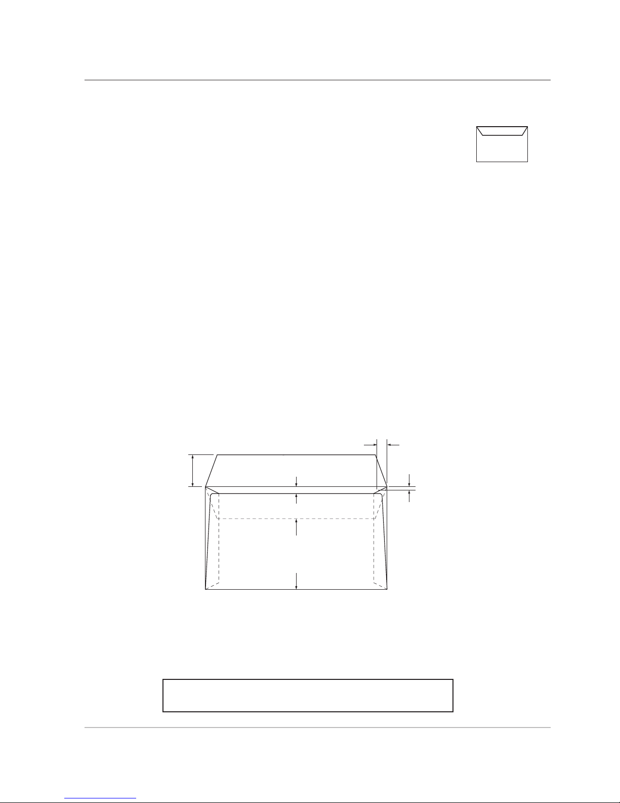
Envelope ap and throat requirements:
DEPTH
WIDTH
Min 25.5mm
Max 63mm
Min 6mm
Max 41mm
19mm
Min 1.6mm
Max 6mm
throat depth
at 19mm in from
edge of envelope
Closed ap tip should not
come closer than
44mm to bottom
of envelope
ALL SPECIFICATIONS ARE SUBJECT TO CHANGE WITHOUT
NOTIFICATION AND ARE SUBJECT TO TEST

2-4 SDT333A DI380/DI425/SI3300/SI3500 Service Manual
2 • Specifications
2.2 MACHINE SPECIFICATIONS
Physical Dimensions DI380/SI3300 DI425/SI3500
Length 773mm 1043mm
Depth 568mm 568mm
Height 525mm 525mm
Weight 55kg 65kg
Weight will depend on machine conguration. Weights stated do not include material.
Noise Level
Running 73dBA
Electrical 230VAC, 50Hz, 3A
or 110VAC, 60Hz, 6A
Maximum Speed DI380/SI3300 - Up to a maximum of 3,000 cycles per hour
DI425/SI3500 - Up to a maximum of 3,500 cycles per hour
Depending on model, fold type and material quality.
Compliance It is certied that the Folding/Inserting machine complies with the
requirements of the Low Voltage Directive 73/23/EEC and the EMC
Directive 89/336/EEC. The product was tested in a typical conguration.
For a formal Declaration of Conformity please contact Compliance
Engineering on +44 (0)1279 426731.
ALL SPECIFICATIONS ARE SUBJECT TO CHANGE WITHOUT
NOTIFICATION AND ARE SUBJECT TO TEST

SDT333A DI380/DI425/SI3300/SI3500 Service Manual
3-1
3 • Theory of Operation
3 • Theory of Operation
Note:
Before any job commences, it is assumed that all the appropriate trays are lled to complete
the sequences described below.
Please refer to relevant diagrams in Section 10- Diagrams
3.1 INTRODUCTION TO SYSTEM THEORY
The DI380/SI3300 and DI425/SI3500 are low volume easy to use Folding/Inserting machines, each
available in 3 variants (1, 2 and 3 station machines).
The sheet feeder(s) have self centring guides and automatic separation based on photo copier
technology. Therefore the documents do not require shingling before the they are presented to the
separator roller and pad. The sheet feeders have a sprung lift plate that lifts the weight of the documents
up to the separator roller to ensure only a single document is fed.
The insert feeder has a more traditional type of separation, by means of a manual height adjustment
and a stone/shield setting that is operator settable. This is to enable diverse material to be processed
through the insert feeder.
The envelope feeder will automatically separate a stack of envelopes to ensure only a single envelope
is fed. The separator height is set by the engineer.
When the Start button is pressed, a single sheet is fed into the paper path and driven into fold plate
1. When the sheet reaches the deector stop, the paper is buckled. This buckled edge is then pulled
through fold rollers 2 and 3 which creates the rst fold. It then enters fold plate 2 until it reaches the
deector stop, where the sheet is buckled again. The edge is pulled into fold rollers 3 and 4, creating
the second fold. At this stage, if an insert is programmed as part of the job, the insert will ‘red’ into the
waiting document.
The envelopes are fed aps up and trailing through the apper unit where the envelope ap is peeled
away from the body of the envelope.The envelope then passes through to the Q station area where it
is stopped. The ap of the envelope is held back by the brush. The envelope is opened when the ipper
ngers press down on the back of the envelope and four insertion ngers enter the envelope throat.
The folded sheet (package) at fold rollers 3 and 4, travels through the transport plate rollers and is
driven into the waiting envelope by the insert drive rollers. Once the insert fully enters the envelope,
the Q station ngers lift up and the package then travels along to the sealer rollers where moisture is
applied to the envelope ap. The body of the envelope is forced up into the inverter stop, this in turns
forces the envelope back into the nip of the sealer rollers and presses the ap against the body of the
envelope.
The envelope activates the exit switch as it passes the exit rollers and increments the counter by
one.

3-2 SDT333A DI380/DI425/SI3300/SI3500 Service Manual
3 • Theory of Operation
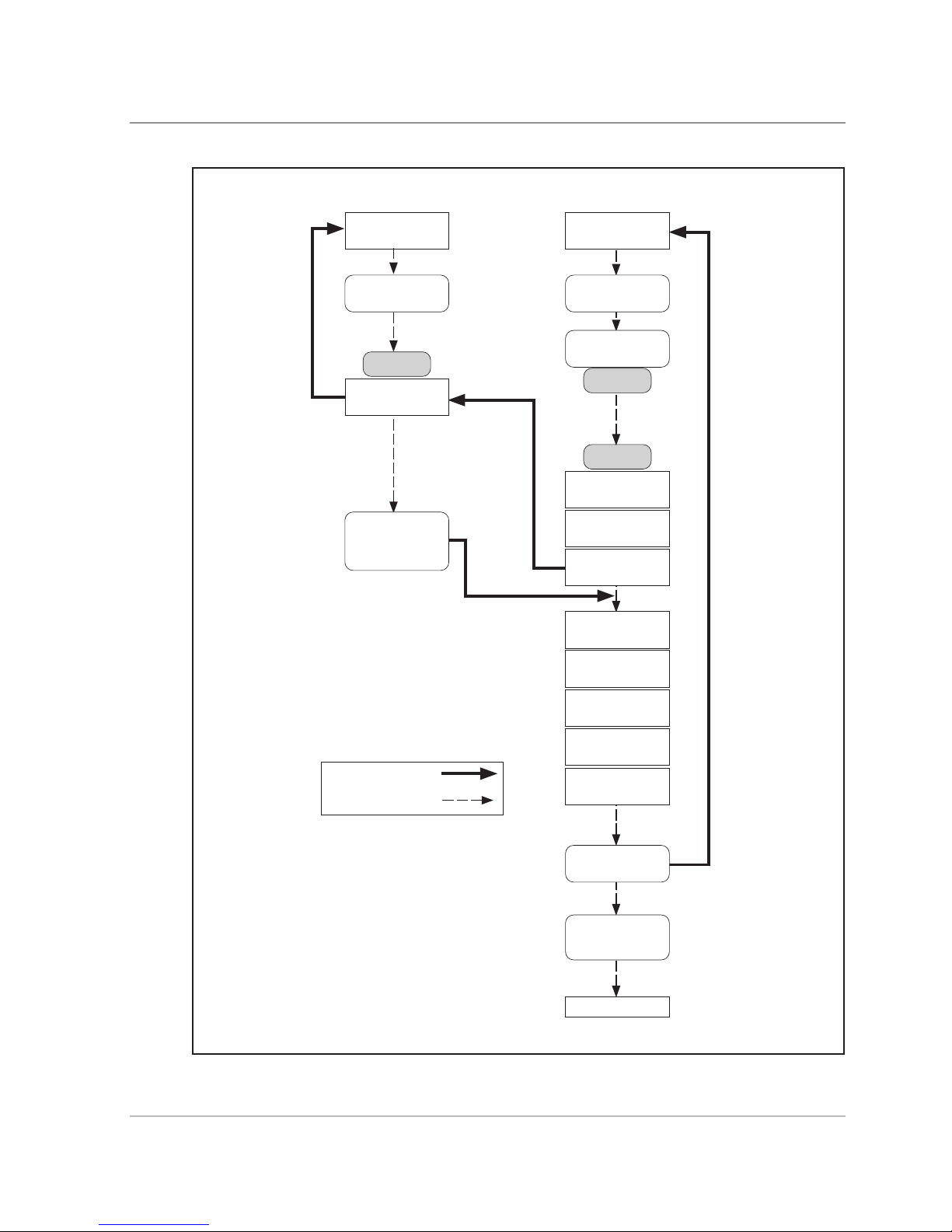
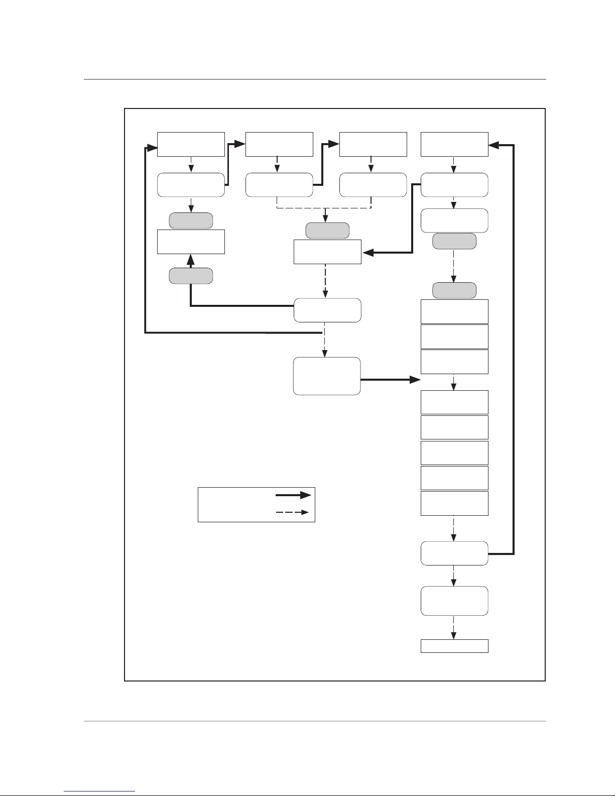
3.2 SINGLE SHEET FEEDER MODE & LINKED FEEDER MODE
When the start button is pressed, the sheet feeder motor (M1) is switched on. This feeds a sheet over
the Double Document Detector (DDD1) sensor and stops it, after a counted delay, in the collation nip.
This results in the sheet being slightly over driven.
At the same time, the envelope motor (M9) is switched on and an envelope is fed through the separator
pad and roller. When the lead edge of the envelope moves forward to the envelope sensor (S1), the
software sends the signal to turn on the collation motor (M5). The transported envelope stops in the
insertion area at a predetermined time according to the size of envelope programmed within the job
setup.
The insertion solenoid (L1) energizes, followed by the hold down solenoid (L2), and nally, by the shoe
horn solenoid (L3).
The next sheet fed from the sheet feeder is triggered by the previous sheet fed entering the fold plate
2 sensor OP14. When the folded sheet enters onto the pivot plate, this moves the ag out of sensor
(OP5). When the folded sheet is fully inserted, the pivot plate moves backwards returning the ag to
its home position.
This operation triggers the software to energize the nger solenoid (L4), lifting the ngers and lifting the
brush of the sealer by energizing solenoid (L5). It will then de-energize the hold down solenoid (L2),
insertion solenoid (L1), and the shoe horn solenoid (L3).
The envelope is then driven from the insertion area into the sealer area. The next envelope is fed when
the lead edge of the envelope pushes the moistener sensor (S3) forward (the software will increment by
a count of 1 for the EIU). The envelope then enters the inverter area and nally exits into the stacker.
The exit sensor (S4) will increment the mechanical counter (located behind the manual advance knob
door) by 1.
In normal run mode, if no material has been detected at the Double Document Detection sensor, the
sheet feeder motor (M1) will time-out after approximately 2 seconds. This is to clean the separator
roller and pad. In 'daily mail' (manual feed) mode, this time is increased to approximately 20 seconds
for operator loading. The manual feed lever opens the gap between the separator roll and pad.
In switchable mode, the software will activate sheet feeder 2 automatically if the tray empty sensor
(OP9) detects that no paper is present in sheet feeder 1 when the document has entered fold plate 2
(OP14).
The software will then switch back to running sheet feeder 1 when the sheet feeder 2 tray empty sensor
(OP10) detects that no paper is present in sheet feeder 2 when the document has entered fold plate
2 (OP14).
This sequence is shown in ow chart form on the following page.

SDT333A DI380/DI425/SI3300/SI3500 Service Manual
3-3
3 • Theory of Operation
Flow Diagram - Single Sheet Feeder Mode
Sheet Feeder
Motor M1 (OP9)
Sheet Feeder
DDD 1 Sensor
Stop
Collation Motor
M5
Fold Plate 2
Sensor OP14
Transport Pivot
Plate
Unblocked/Blocked
Sensor OP5
Envelope Motor M9
ON
Envelope Sensor S1
ON
Lead Edge Sensor S2
ON
Delay
Stop
Insertion Solenoid L1
ON
Hold Down Solenoid
L2 ON
Shoe Horn Solenoid
L3 ON
Finger Solenoid L4
ON
Sealer Solenoid L5
ON
Insertion Solenoid L1
OFF
Hold Down Solenoid
L2 OFF
Moistener Sensor
(Software Counter) S3
Exit Sensor
(Mechanical Item
Counter) S4
EXIT
SOFTWARE TRIGGER
PAPER PATH
Shoe Horn Solenoid
L3 OFF
Sheet Feeder
Motor M2 (OP10)
Sheet Feeder
DDD 2 Sensor

3-4 SDT333A DI380/DI425/SI3300/SI3500 Service Manual
3 • Theory of Operation
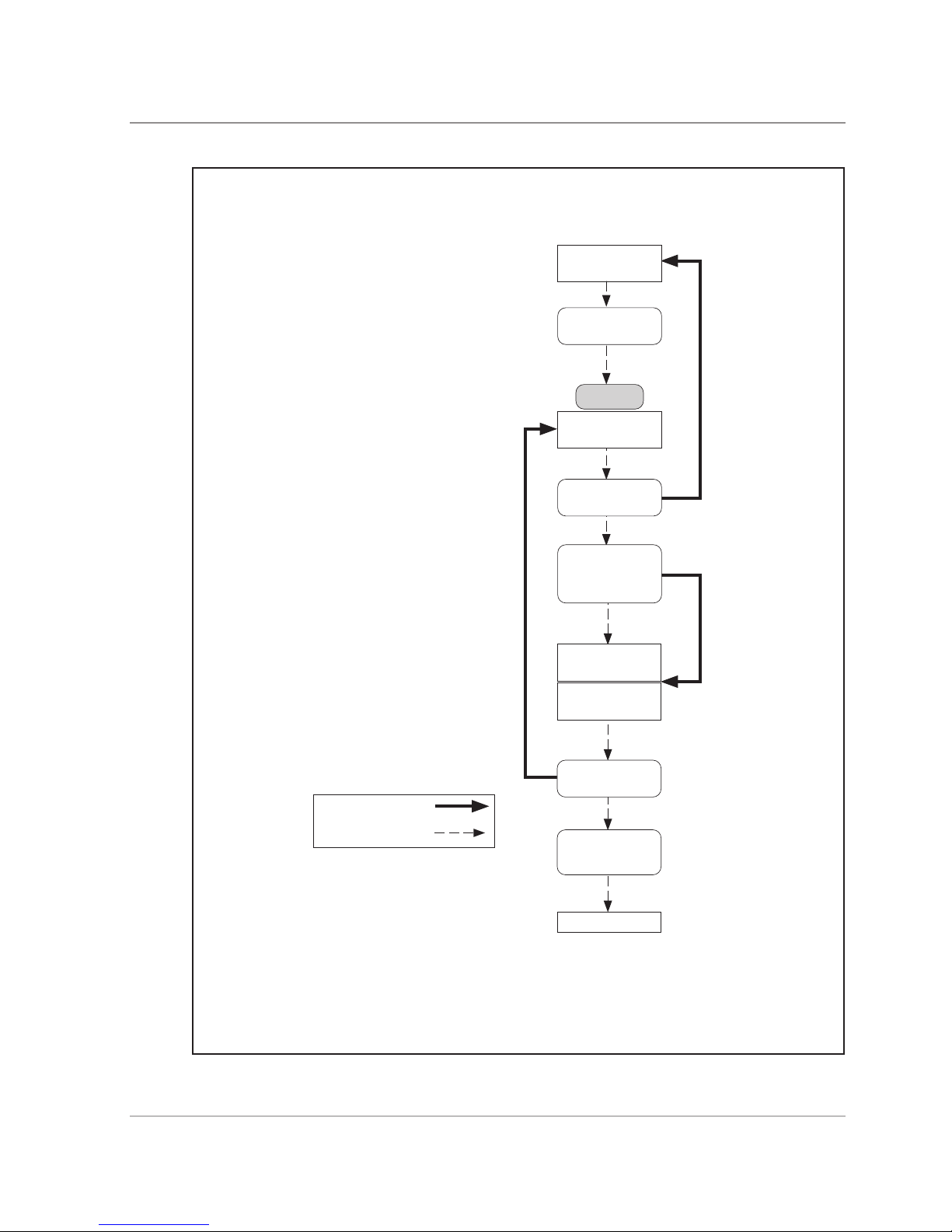
3.3 INSERT FEEDER MODE
When the start button is pressed, two motors control the transport of the insert. The insert pre-feeder
motor (M3) is energized and feeds a single insert past the Double Document Detection (DDD3) sensor.
If a double is detected, the machine will stop and the double insert symbol will be indicated on the
control panel. If no double is detected, the insert will continue to the insert collation area and stop.
At the same time, the envelope motor (M9) is energized. An envelope is fed through the separator pad
and roller.
The transported envelope will stop in the insertion area at a predetermined time according to the size
of envelope programmed within the job setup.
The insertion solenoid (L1) energizes, followed by the hold down solenoid (L2), and nally, by the shoe
horn solenoid (L3).
When the shoe horn solenoid is energized, the software sends a signal to operate the insert collation
motor (M4). This will trigger the next insert to be fed into the collation insert area.
When the insert enters onto the pivot plate, this moves the ag out of sensor (OP5). When the insert
is fully inserted, the pivot plate moves backwards returning the ag to its home position.
This operation triggers the software to energize the nger solenoid (L4), lifting the ngers and lifting the
brush of the sealer by energizing solenoid (L5). It will then de-energize the hold down solenoid (L2),
insertion solenoid (L1), and the shoe horn solenoid (L3).
The envelope will then be driven from the insertion area into the sealer area. The next envelope will
be fed when the lead edge of the envelope pushes the moistener sensor (S3) forward (the software
will increment by a count of 1 for the EIU). The envelope will then enter the inverter area and then exit
into the stacker.
The exit sensor (S4) will increment the mechanical counter (located behind the manual advance knob
door) by 1.
This sequence is shown in ow chart form on the following page.
SDT333A DI380/DI425/SI3300/SI3500 Service Manual
3-5
3 • Theory of Operation
Flow Diagram - Insert Feeder Mode
Insert Pre-Feed
Motor M3
Insert
DDD 3 Sensor
Stop
Insert Collation Motor
M4
Transport Pivot
Plate
Unblocked/Blocked
Sensor OP5
Envelope Motor M9
ON
Envelope Sensor S1
ON
Lead Edge Sensor S2
ON
Delay
Stop
Insertion Solenoid L1
ON
Hold Down Solenoid
L2 ON
Shoe Horn Solenoid
L3 ON
Hold Down Solenoid
L2 OFF
Insertion Solenoid L1
OFF
Shoe Horn Solenoid
L3 OFF
Moistener Sensor
(Software Counter) S3
Exit Sensor
(Mechanical Item
Counter) S4
EXIT
SOFTWARE TRIGGER
PAPER PATH
Sealer Solenoid L5
ON
Finger Solenoid L4
ON

3-6 SDT333A DI380/DI425/SI3300/SI3500 Service Manual
3 • Theory of Operation
3.4 TWO SHEET FEEDER MODE
When the start button is pressed, the sheet feeder motor (M1) is switched on. This feeds a sheet over
the Double Document Detector (DDD1) sensor. This triggers sheet feeder motor (M2) to feed a sheet
up to the Double Document Detector (DDD2). Both sheets stop, after a counted delay, in the collation
nip. This results in the sheets being slightly over driven.
At the same time, the envelope motor (M9) is switched on and an envelope is fed through the separator
pad and roller. When the lead edge of the envelope moves forward to the envelope sensor (S1), the
software sends the signal to turn on the collation motor (M5). The transported envelope will stop in the
insertion area at a predetermined time according to the size of envelope programmed within the job
setup.
The insertion solenoid (L1) energizes, followed by the hold down solenoid (L2), and nally, by the shoe
horn solenoid (L3).
The next sheet fed from the sheet feeder 1 is triggered by the previous sheet fed entering the fold plate
2 sensor OP14. When the folded sheet enters onto the pivot plate, this moves the ag out of sensor
(OP5). When the folded sheet is fully inserted, the pivot plate moves backwards returning the ag to
its home position.
This operation triggers the software to energize the nger solenoid (L4), lifting the ngers and lifting the
brush of the sealer by energizing solenoid (L5). It will then de-energize the hold down solenoid (L2),
insertion solenoid (L1), and the shoe horn solenoid (L3).
The envelope is then driven from the insertion area into the sealer area. The next envelope is fed when
the lead edge of the envelope pushes the moistener sensor (S3) forward (the software will increment by
a count of 1 for the EIU). The envelope then enters the inverter area and nally exits into the stacker.
The exit sensor (S4) will increment the mechanical counter (located behind the manual advance knob
door) by 1.
This sequence is shown in ow chart form on the following page.
SDT333A DI380/DI425/SI3300/SI3500 Service Manual
3-7
3 • Theory of Operation
Flow Diagram - Two Sheet Feeder Mode
Sheet Feeder
Motor M1
Sheet Feeder
DDD 1 Sensor
Stop
Collation Motor
M5
Transport Pivot
Plate
Unblocked/Blocked
Sensor OP5
Envelope Motor M9
ON
Envelope Sensor S1
ON
Lead Edge Sensor S2
ON
Delay
Stop
Insertion Solenoid L1
ON
Hold Down Solenoid
L2 ON
Shoe Horn Solenoid
L3 ON
Hold Down Solenoid
L2 OFF
Insertion Solenoid L1
OFF
Shoe Horn Solenoid
L3 OFF
Moistener Sensor
(Software Counter) S3
Exit Sensor
(Mechanical Item
Counter) S4
EXIT
SOFTWARE TRIGGER
PAPER PATH
Sealer Solenoid L5
ON
Sheet Feeder
Motor M2
Sheet Feeder
DDD 2 Sensor
Fold Plate 2
Sensor OP14
Finger Solenoid L4
ON

3-8 SDT333A DI380/DI425/SI3300/SI3500 Service Manual
3 • Theory of Operation
3.5 SINGLE SHEET FEEDER PLUS AN INSERT MODE
When the start button is pressed two motors control the transport of the insert. The insert pre-feeder
motor (M3) is energized and feeds a single insert past the Double Document Detection (DDD3) sensor.
If a double is detected, the machine will stop and the double insert symbol will be indicated on the
control panel. If no double is detected, the insert will continue to the insert collation area and stop.
The sheet feeder motor (M1) triggered by the insert passing through the Double Document Detection
and feeds the sheet over the Double Document Detector (DDD1) sensor and stops after a counted
delay in the collation nip. This will result in the sheet being slightly over driven.
At the same time the envelope motor (M9) is energized. An envelope is fed through the separator pad
and roller.
When the lead edge of the envelope moves forward to the envelope sensor (S1), the software sends
the signal to energize the collation motor (M5) to switch on. The transported envelope will stop in the
insertion area at a predetermined time according to the size of the envelope programmed within the
job setup.
The insertion solenoid (L1) energizes, followed by the hold down solenoid (L2), and nally, by the shoe
horn solenoid (L3).
When the sheet enters fold plate 2, covering sensor OP14, the software switches on the insert motor
(M4) after a timed delay. This delay is the "nesting constant" set in the parameter screen.
The next insert is fed after the rst insert is nested into the folded sheet.
When the folded sheet and insert enter onto the pivot plate, this moves the ag out of sensor (OP5).
When the insert is fully inserted, the pivot plate moves backwards returning the ag to its home
position.
This operation triggers the software to energize the nger solenoid (L4), lifting the ngers and lifting the
brush of the sealer by energizing solenoid (L5). It will then de-energize the hold down solenoid (L2),
insertion solenoid (L1), and the shoe horn solenoid (L3).
The envelope is then driven from the insertion area into the sealer area. The next envelope is fed when
the lead edge of the envelope pushes the moistener sensor (S3) forward (the software will increment by
a count of 1 for the EIU). The envelope then enters the inverter area and nally exits into the stacker.
The exit sensor (S4) will increment the mechanical counter (located behind the manual advance knob
door) by 1.
This sequence is shown in ow chart form on the following page.

SDT333A DI380/DI425/SI3300/SI3500 Service Manual
3-9
3 • Theory of Operation
Flow Diagram - Single Sheet Feeder Plus an Insert Mode
Sheet Feeder
DDD 1 Sensor
Insert Pre-Feed
Motor M3
Insert Feeder
DDD 3 Sensor
Stop
Collation Motor
M5
Transport Pivot
Plate
Unblocked/Blocked
Sensor OP5
Envelope Motor M9
ON
Envelope Sensor S1
ON
Lead Edge Sensor S2
ON
Delay
Stop
Insertion Solenoid L1
ON
Hold Down Solenoid
L2 ON
Shoe Horn Solenoid
L3 ON
Hold Down Solenoid
L2 OFF
Insertion Solenoid L1
OFF
Shoe Horn Solenoid
L3 OFF
Moistener Sensor
(Software Counter) S3
Exit Sensor
(Mechanical Item
Counter) S4
EXIT
SOFTWARE TRIGGER
PAPER PATH
Sealer Solenoid L5
ON
Sheet Feeder
Motor M1
Fold Plate 2
Sensor OP14
Stop
Insert Motor
M4
Delay
Finger Solenoid L4
ON

3-10 SDT333A DI380/DI425/SI3300/SI3500 Service Manual
3 • Theory of Operation
3.6 TWO SHEET FEEDERS PLUS AN INSERT MODE
When the start button is pressed. The insert pre-feeder motor (M3) is energized and feeds a single
insert past the Double Document Detection (DDD3) sensor. If a double is detected, the machine will
stop and the double insert symbol will be indicated on the control panel. If no double is detected, motor
(M4) will energies and will feed the insert into to the insert collation area and stop.
The sheet feeder motor (M1) is triggered by the insert passing through the Double Document Detection
(DDD3), feeds the sheet over the Double Document Detector (DDD1). The Double Document Detector
(DDD1) triggers sheet feeder motor (M2) to feed the sheet through the Double Document Detector
(DDD2), both sheets stop, after a counted delay, in the collation nip. This will result in the sheets being
slightly over driven.
At the same time, the envelope motor (M9) is energized. An envelope is fed through the separator pad
and roller.
When the lead edge of the envelope moves forward to the envelope sensor (S1), the software sends
the signal to energize the collation motor (M5).
The transported envelope will stop in the insertion area at a predetermined time according to the size
of envelope programmed within the job setup.
The insertion solenoid (L1) energizes, followed by the hold down solenoid (L2), and nally, by the shoe
horn solenoid (L3).
When the sheet enters fold plate 2, covering sensor OP14, the software switches on the insert motor
(M4) after a timed delay. This delay is the "nesting constant" set in the parameter screen.
The next insert is fed after the rst insert is nested into the folded sheets.
When the folded sheets and insert enter onto the pivot plate, this moves the ag out of sensor (OP5).
When the insert is fully inserted, the pivot plate moves backwards returning the ag to its home
position.
This operation triggers the software to energize the nger solenoid (L4), lifting the ngers and lifting the
brush of the sealer by energizing solenoid (L5). It will then de-energize the hold down solenoid (L2),
insertion solenoid (L1), and the shoe horn solenoid (L3).
The envelope is then driven from the insertion area into the sealer area. The next envelope is fed when
the lead edge of the envelope pushes the moistener sensor (S3) forward (the software will increment by
a count of 1 for the EIU). The envelope then enters the inverter area and nally exits into the stacker.
The exit sensor (S4) will increment the mechanical counter (located behind the manual advance knob
door) by 1.
This sequence is shown in ow chart form on the following page.
SDT333A DI380/DI425/SI3300/SI3500 Service Manual
3-11
3 • Theory of Operation
Flow Diagram - Two Sheet Feeders Plus an Insert Mode
Transport Pivot
Plate
Unblocked/Blocked
Sensor OP5
Insert Pre-Feed
Motor M3
Insert Feeder
DDD 3 Sensor
Envelope Motor M9
ON
Envelope Sensor S1
ON
Lead Edge Sensor S2
ON
Delay
Stop
Insertion Solenoid L1
ON
Hold Down Solenoid
L2 ON
Shoe Horn Solenoid
L3 ON
Hold Down Solenoid
L2 OFF
Insertion Solenoid L1
OFF
Shoe Horn Solenoid
L3 OFF
Moistener Sensor
(Software Counter) S3
Exit Sensor
(Mechanical Item
Counter) S4
EXIT
SOFTWARE TRIGGER
PAPER PATH
Sealer Solenoid L5
ON
Stop
Insert Motor
M4
Delay
Finger Solenoid L4
ON
Sheet Feeder
Motor M1
Sheet Feeder
DDD 1 Sensor
Stop
Collation Motor
M5
Sheet Feeder
Motor M2
Sheet Feeder
DDD 2 Sensor
Fold Plate 2
Sensor OP14

3-12 SDT333A DI380/DI425/SI3300/SI3500 Service Manual
3 • Theory of Operation
3.7 THE FOLD ONLY MODE
When the start button is pressed, the sheet feeder motor (M1) is switched on. This feeds a sheet over
the Double Document Detector (DDD1) sensor. The sheet stops, after a counted delay, in the collation
nip. This results in the sheet being slightly over driven.
The software disables the envelope motor (M9) and envelope sensor (S1) and sends the signal to turn
on the collation motor (M5).
The next sheet fed from the sheet feeder will be triggered by the previous sheet fed entering the fold
plate 2 sensor OP14. When the folded sheet enters onto the pivot plate, this moves the ag out of
sensor (OP5). The pivot plate moves backwards and returns the ag to its home position.
This operation triggers the software to energize the nger solenoid (L4), lifting the ngers and lifting
the brush of the sealer by energizing solenoid (L5).
The document is then driven from the insertion area into the sealer area. The next document is fed
when the lead edge of the document pushes the moistener sensor (S3) forward (the software will
increment by a count of 1 for the EIU). The document then enters the inverter area and nally exits
into the stacker.
The exit sensor (S4) will increment the mechanical counter (located behind the manual advance knob
door) by 1.
This sequence is shown in ow chart form on the following page.
SDT333A DI380/DI425/SI3300/SI3500 Service Manual
3-13
3 • Theory of Operation
Flow Diagram - The Fold Only Mode
Sheet Feeder
Motor M1
Sheet Feeder
DDD 1 Sensor
Stop
Collation Motor
M5
Fold Plate 2
Sensor OP14
Transport Pivot
Plate
Unblocked/Blocked
Sensor OP5
Finger Solenoid L4
ON
Sealer Solenoid L5
ON
Moistener Sensor
(Software Counter) S3
Exit Sensor
(Machanical Item
Counter) S4
EXIT
SOFTWARE TRIGGER
PAPER PATH
First cycle does not
stop at the collation
motor.

3-14 SDT333A DI380/DI425/SI3300/SI3500 Service Manual
3 • Theory of Operation
3.8 ACCUMULATION FROM MAIN SHEET FEEDER
After a trial piece has been processed and the start button is pressed, the sheet feeder motor (M1) is
switched on. This feeds a sheet over the Double Document Detector (DD1) sensor and stops it, after
a counted delay, in the collation nip. This results in the sheet being slightly over driven.
At the same time, the envelope motor (M9) is switched on and an envelope is fed through the separator
pad and roller. When the lead edge of the envelope moves forward to the envelope sensor (S1), the
software sends the signal to turn on the collation motor (M5). The transported envelope stops in the
insertion area at a predetermined time according to the size of envelope programmed within the job
setup.
The insertion solenoid (L1) energizes, followed by the hold down solenoid (L2), and nally, by the shoe
horn solenoid (L3).
Depending on fold type the sheet will be fed through the fold rollers and fold plates.
The folded sheet enters onto the pivot plate this moves the ag out of sensor (OP5). When the folded
sheet is fully inserted, the pivot plate moves backwards returning the ag to its home position this de-
energizes the hold down solenoid (L2) and the shoe horn solenoid (L3)
L3 energizes again placing the shoe horn back into the envelope lifting the previous folded documents
up.
The software sends the signal to turn on the collation motor (M5) sending the next sheet down through
the fold rollers and fold plates onto the pivot plate. This happens until the predetermined sheets are
inserted into the envelope. After the last document has entered the envelope the pivot plate moves the
ag out of the sensor (OP5).
This operation then triggers the software to energize the nger solenoid (L4), lifting the ngers and
lifting the brush of the sealer by energizing solenoid (L5) and the insertion solenoid (L1). The shoe horn
at this point stays energized until the package passes the moistener sensor (S3).
The envelope is driven from the insertion area into the sealer area. The next envelope is fed when the
lead edge of the envelope pushes the moistener sensor (S3) forward (the software will be Incremented
by a count of 1 for the EIU). The envelope then enters the inverter area and nally exits into the
stacker.
The exit sensor (S4) will increment the mechanical counter (located behind the manual advance knob
door) by 1.
In normal run mode, if no material has been detected at the Double Document Detection sensor, the
sheet feeder motor (M1) will time-out after approximately 2 seconds. This is to clean the separator
roller and pad. In 'daily mail' (manual feed) mode, this time is increased to approximately 20 seconds
for operator loading. The manual feed lever opens the gap between the separator roll and pad.
This sequence is shown in ow chart form on the following page.
SDT333A DI380/DI425/SI3300/SI3500 Service Manual
3-15
3 • Theory of Operation
Flow Diagram - Accumulation for Sheet Feeder 1 Mode
Envelope Motor M9
ON
Envelope Sensor S1
ON
Stop
Insertion Solenoid L1
Off
Insertion Solenoid L1
ON
Hold Down Solenoid
L2 ON/OFF
Shoe Horn Solenoid
L3 ON/OFF
Finger Solenoid L4
ON
Sealer Solenoid L 5
ON
Shoe Horn Solenoid
L3 OFF
Lead Edge Sensor S2
ON
Transport Pivot Plate
Unblocked/Blocked
Sensor OP5
Moistener Sensor S3
(Software Counter)
Sheet Feeder DDD 1
Sensor
Exit Sensor S 4
(Mechanical Item
Counter)
Stop
Delay
EXIT
Collation Motor M5
SOFTWARE TRIGGER
PAPER PATH
Sheet Feeder Motor
M1 (OP9)
Fold Plate 2 Sensor
OP14
3-16 SDT333A DI380/DI425/SI3300/SI3500 Service Manual
3 • Theory of Operation
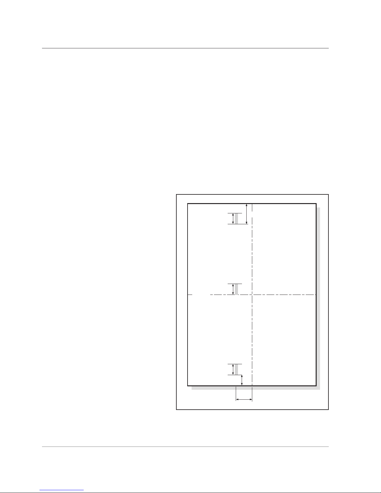
3.9 DOUBLE DETECT SENSORS
only adjustable in the service parameters screen and are not operator selectable. This is to allow the
engineer to choose different detection reference points to suit the customer’s application.
Sheet Feeder 1 and Sheet Feeder 2 have three positions available: LEAD, MIDDLE and TRAIL. The
Insert feeder has only the one option: LEAD.
The Detection sensors work on an LED emmiting through the thickness of the paper onto a Opto
detector. The double detection takes 14 reference points in a 22mm window. There are 7 “High” and 7
“Low”. From these readings, the software will take 7 relevant readings. The sensor is positioned 50mm
to the left of the centre line.
On the LEAD position, the double detection will start reading at approximately 22mm from the lead
edge of the document in the direction of feed. When a double is detected, the machine will stop and
the document will be in the collation nip area. The machine will indicate which feeder the double has
been fed from on the control panel.
On the MIDDLE position (not available
on the inser t feede r) th e dou ble
detection will start halfway down the
document. This is taken from the “length
of paper” entered in the “Job Set Up
Menu”. When a double is detected, the
machine will stop and the document will
be in the insertion area. The machine
will indicate which feeder the double has
been fed from on the control panel.
On the TRAIL position (not available on
the insert feeder) the double detection
will start approximately 45mm from
the trail edge of the document in the
direction of feed. This is taken from the
“length of paper” entered in the “Job Set
Up Menu”. When a double is detected,
the machine will stop with the document
inserted and fed into the stacker area.
The machine will display “Double Check
Stacker” and also indicate which feeder
the double was fed from on the control
panel.
DDD Scan Areas
45mm
TRAIL
22mm
LEAD
50mm
MIDDLE
22mm
22mm
22mm
centre line
centre line
 Loading...