


Solstice Gas ROV Fryers
SSHLV Series
Service Manual
RETAIN AND STORE THIS MANUAL IN A SAFE PLACE FOR FUTURE USE
L22-392 R1 (10/14)
Pitco SSHLV (ROV) Gas Fryers
! DANGER !
Improper installation, operation, adjustment, maintenance, all alterations or service, and unauthorized alterations or modifications can cause property damage, injury or death. Read the installation, operating and service manuals thoroughly before installing or servicing this equipment.
! WARNING !
DO NOT supply the appliance with a gas that is not indicated on the data plate. If conversion of the appliance is required, contact your dealer or authorized service agent.
! DANGER !
Only qualified service personnel may service or convert this appliance to use a gas other than that for which it was originally manufactured. Improper conversion can lead to property damage, injury or death.
! DANGER !
Prior to moving, testing, maintaining or repairing your appliance, ensure it is emptied of all oil, cool, disconnected from gas and all electrical power. Failure to do so may result in property damage, damage to your fryer, injury or death.
! DANGER !
No structural material on the fryer should be altered or removed to accommodate placement of the fryer under a hood, or any other reason. Unauthorized modifications could cause improper combustion and excess heat, causing property damage, injury and death.
! DANGER !
Adequate means must be provided to limit the movement of this appliance without depending on the gas line. Single fryers equipped with legs must be stabilized by installing anchor straps. All fryers equipped with casters must be stabilized by installing restraining lanyards. If a flexible gas line is in use, an additional restraining lanyard must be connected at all times when the fryer is in use. The restraining cable must NOT exceed 80% of the length of the flexible gas line. Failure to do so may result in ruptured gas lines and property damage, injury and death.
! DANGER !
DO NOT sit or stand on this appliance. The appliance’s top deck, door, front panel, tank, splash back, tank cover, workshelf, drain board are not steps. Serious injury will result from slipping, falling or contact with hot liquids causing property damage, injurious severe burns and/or death.
! DANGER !
NEVER use the appliance as a step for cleaning or accessing the ventilation hood. Serious injury will result from slipping, falling or contact with hot liquids causing property damage, injurious severe burns and/or death.
! DANGER !
Do not store or use gasoline, store or spray aerosols or other flammable liquids or vapors in the vicinity of this or any other appliance. Appliances incorporate open flames and/or high heat that will ignite flammable vapors causing property damage, injury and death.
L22-392 R1 |
2 |
Pitco SSHLV (ROV) Gas Fryers
! DANGER !
Instructions to be followed, in the event an operator smells/detects a gas leak, must be posted in a prominent location. This information can be obtained from your local gas company or supplier. Failure to post the instructions could leave an active gas leak unresolved, leading to fire, property damage, injury and death.
! DANGER !
The contents of the crumb catch and/or filter pan of any filter system must be emptied into a fireproof container at the end of the frying operation each day. Some food particles can spontaneously combust into flames if left soaking in certain oil/shortening materials, causing fire, property damage, injury and death.
! DANGER !
Any and all spilled oil, water or other liquids that occurs as a result of operation, cleaning, maintenance or repair of this fryer should immediately be cleaned and dried. Failure to do so can create a slippery surface resulting in falling/impact injury or death.
! DANGER !
Check for gas leaks after installation or servicing of a gas fryer. Apply a leak detection solution to all connections and joints to ensure there are no bubbles or leaks. Failure to check for and correct any leaks could lead to fire and/or explosion, property damage, injury and death.
! WARNING !
DO NOT use the filter pan to transport oil, hot or cold. The filter pan is not designed to transport oil.
Serious injury will result from slipping, falling or contact with hot liquids causing property damage, injurious severe burns and/or death.
! WARNING !
DO NOT remove frypot fittings before all oil is drained from the tank. Serious injury will result from slipping, falling or contact with hot liquids causing property damage, injurious severe burns and/or death.
! WARNING !
For appliances equipped with manual (opposed to automated) filtration, shut down the appliance completely when the shortening, fat or oil is being drained from the appliance. This will prevent the appliance inadvertently heating up during the draining and filtering process.
! WARNING !
This appliance must be installed and used in such a way that any water cannot contact the fat or oil.
Water will react violently with hot fat or oil causing severe burns, injury or death.
! WARNING !
Keep all items and hands out of drains. Automated actuators may close without notice causing damage to the fryer and personal injury.
! WARNING !
This appliance is NOT jet stream approved. Do not clean the appliance with a water jet. Use of any pressurized water jet will cause damage to the fryer and personal injury.
L22-392 R1 |
3 |
Pitco SSHLV (ROV) Gas Fryers
! WARNING !
This appliance is intended for indoor use only. Do NOT use outdoors.
! WARNING !
This appliance is not intended for use by persons (including children) with reduced physical, sensory or mental capabilities, or lack of experience and knowledge. Property damage, personal injury or death can result from unqualified operators.
! CAUTION !
Use caution and wear appropriate safety equipment to avoid contact with hot oil or surfaces. Hot oil and surfaces can cause severe burns and injury.
! CAUTION !
Do not bang fry baskets or other utensils on the joining strips between batteried fry pots. Banging frybaskets or any other utensil on the joining strip will distort and promote oil migration inside the fryer.
! CAUTION !
NEVER run water through the filter pump. Water will damage the pump seals and render the pump inoperable/ It will also void the warranty on the filter pump.
NOTE
Some US states require any gas appliance to be installed by a state licensed plumber or pipe fitter. Check with your local municipality prior to installation.
NOTE
This equipment must be installed in accordance with appropriate local and national codes in the state, country and/or region in the appliance is to be operated. Contact your local gas authority for guidance.
NOTE
This equipment is to be installed in compliance with the basic plumbing code of the Building Officials and
Code Administration International (BOCA) and the Food Service Sanitation Manual of the U.S Food and Drug Administration.
NOTE
Photos and drawings used in this manual are intended to illustrate operational, cleaning and technical procedures and may not conform to onsite management operational procedures.
NOTE
This appliance is intended to be used for commercial applications: For example in kitchens of restaurants, canteens, hospitals and in commercial enterprises such as bakeries, butcheries, etc. but NOT for continuous mass production of food.
NOTE
This appliance is intended for professional use only and is to be operated by qualified, trained personnel only. A Pitco Authorized Service Agent (ASA) or other qualified professional must perform installation, maintenance and repairs. Installation or repairs by unqualified personnel will void the manufacturer’s warranty. See chapter one for descriptions of qualified personnel.
L22-392 R1 |
4 |
Pitco SSHLV (ROV) Gas Fryers
NOTE
If, during the warranty period, the end user uses a part for this Pitco appliance other than an UNMODIFIED new part purchased directly from Pitco or any of Pitco’s authorized service agents, and/or the part being used is modified from its original configuration, THE WARRANTY WILL BE VOID. Further, Pitco Frialator and its affiliates will not be liable for any claims, damages or expenses incurred by the customer which arise directly or indirectly, in whole or in part, due to the installation of any modified part and/or part received from an unauthorized servicer/supplier.
1 Notice
In the event of problems or questions about your order, contact the Pitco Frialator factory at
(603) 225-6684.
For non-routine maintenance or repairs, or for service information, contact your local Pitco Frialator Authorized Service and Parts representative (ASAP). In order to assist you quickly,your Pitco Frialator ASAP or Service Department representative requires certain information about your equipment. Most of this information is printed on a data plate affixed to the inside of the fryer door. Part numbers are found in the Service and Parts Manual. Parts orders may be placed directly with your local ASAP or distributor. A list of Pitco Factory Authorized Service and Parts is located on the Pitco Frialator website at www.pitco.com. If you do not have access to this list, contact the Pitco Frialator Service Department at (603) 225-6684 or by email at:
Literature Fulfillment (brochures, spec sheets, manuals)
Literature@Pitco.com
Non-urgent service parts inquires. i.e. (part numbers or reference information) parts@pitco.com
Non-urgent technical service questions service@pitco.com
Non-urgent warranty questions warranty@pitco.com
MAILING ADDRESS Pitco Frialator
P.O. Box 501
Concord, NH 03302-0501 SHIPPING ADDRESS Pitco Frialator
10 Ferry Street Concord, NH 03301
EQUIPMENT REFERENECE INFORMATION
Model #: __________________________
Serial #: __________________________
Date Purchased: ___________________
L22-392 R1 |
5 |
Pitco SSHLV (ROV) Gas Fryers |
|
||
TABLE OF CONTENTS |
|
||
1 |
Notice ........................................................................................................................................... |
5 |
|
2 |
General......................................................................................................................................... |
8 |
|
2.1 |
Serial Numbers...................................................................................................................... |
9 |
|
2.2 |
Safety Information ............................................................................................................... |
10 |
|
|
2.2.1 Installation, Operating, and Service Personnel ............................................................... |
10 |
|
2.3 |
Definitions............................................................................................................................ |
10 |
|
|
2.3.1 Qualified and/or Authorized Operating Personnel........................................................... |
10 |
|
|
2.3.2 Qualified Installation Personnel....................................................................................... |
10 |
|
2.4 |
Shipping Damage Claim Procedure .................................................................................... |
11 |
|
3 |
Theory of Operation.................................................................................................................. |
11 |
|
3.1 |
The Matchless Ignition System ........................................................................................... |
11 |
|
3.2 |
Auto Filtration Boards.......................................................................................................... |
12 |
|
3.3 |
Thermostats ........................................................................................................................ |
14 |
|
3.4 |
Fryer Sequence Operation .................................................................................................. |
14 |
|
3.5 |
Heating System ................................................................................................................... |
14 |
|
3.6 |
Safety System ..................................................................................................................... |
15 |
|
3.7 |
Filter System (Manual Filtration Only) ................................................................................. |
15 |
|
3.8 |
Basket Lift (Optional)........................................................................................................... |
16 |
|
3.9 |
Auto Top Off – ATO (Optional)............................................................................................ |
16 |
|
3.10 |
Automated Filtration (Optional) ........................................................................................... |
17 |
|
4 |
Accessing Fryer for Servicing ................................................................................................. |
18 |
|
5 |
Replacing the Controllers ........................................................................................................ |
19 |
|
5.1 |
Removing the Controller Front Panel Bezel ........................................................................ |
19 |
|
6 |
Manual Operation of Drain and Return (Auto Filter Only) ..................................................... |
20 |
|
7 |
Blocked Drain (Auto Filter Only).............................................................................................. |
21 |
|
7.1 |
Replacing the Relay Board and Paper ................................................................................ |
22 |
|
8 |
Checking Resistance ................................................................................................................ |
23 |
|
8.1 |
Checking the Resistance of the Transformer ...................................................................... |
23 |
|
8.2 |
Diagram Identifying Terminals for Second Resistance ....................................................... |
24 |
|
8.3 |
Checking the Resistance of the DVI Switch ........................................................................ |
24 |
|
8.4 |
Checking the Resistance of the Hi-Limit ............................................................................. |
25 |
|
8.5 |
Checking the Resistance of the Temperature Probe .......................................................... |
26 |
|
9 |
Replacing Temperature Probe ................................................................................................. |
27 |
|
10 |
Replacing the Ignition Module and Hi-Limit ........................................................................... |
29 |
|
11 |
Replacing an Igniter/Pilot Assembly ....................................................................................... |
30 |
|
12 |
Replacing Drain Valve with Actuator (Auto Filter Only) ........................................................ |
31 |
|
13 |
Replacing the DC Power Supply.............................................................................................. |
33 |
|
14 |
Replacing Transformer/Power Box ......................................................................................... |
34 |
|
15 |
Changing Filter Pump Actuator ............................................................................................... |
35 |
|
16 |
Testing the Auto Top Off Probe (if equipped) ........................................................................ |
36 |
|
17 |
Replacing the Auto Top Off Probe (If equipped).................................................................... |
38 |
|
18 |
Gas Conversion......................................................................................................................... |
40 |
|
19 |
Replacing the Return Valve...................................................................................................... |
41 |
|
20 |
Replacing the Optional Flush Hose Assembly and Valve..................................................... |
42 |
|
21 |
Replacing the Waste Oil and Components............................................................................. |
45 |
|
21.1 Removing Rear Mounting Bracket ...................................................................................... |
45 |
||
21.2 Removing the Check Valve ................................................................................................. |
46 |
||
22 |
Removing the Filter Pump from the Motor ............................................................................. |
48 |
|
22.1 |
Replacing Seal Kit ............................................................................................................... |
48 |
|
23 |
Replacing the Drain Line or Gasket ........................................................................................ |
49 |
|
L22-392 R1 |
6 |
Pitco SSHLV (ROV) Gas Fryers |
|
||
24 |
Replacing the Pump Relay and Circuit Breaker..................................................................... |
50 |
|
24.1 |
Replacing the Circuit Breaker.............................................................................................. |
50 |
|
24.2 |
Replacing the Pump Relay.................................................................................................. |
51 |
|
25 |
Cleaning the Gas Valve Vent Tube .......................................................................................... |
52 |
|
26 |
Checking the Gas Pressure ..................................................................................................... |
53 |
|
26.1 |
Taking a Supply Gas Pressure Reading ............................................................................. |
53 |
|
26.2 |
Taking a Manifold Gas Pressure Reading........................................................................... |
55 |
|
26.3 |
Adjusting Manifold Gas Pressure ........................................................................................ |
56 |
|
26.4 |
Adjusting Pilot Flame........................................................................................................... |
56 |
|
27 |
Replacing the Self-Cleaning Burner Solenoid........................................................................ |
57 |
|
28 |
Replacing the Gas Valve .......................................................................................................... |
58 |
|
29 |
Replacing the DVI Switch (Manual Filter Only)....................................................................... |
60 |
|
30 |
Replacing the Burner Assembly.............................................................................................. |
61 |
|
30.1 |
Replacing the Burner(s) ...................................................................................................... |
61 |
|
30.2 |
Replacing the Burner Assembly .......................................................................................... |
63 |
|
31 |
Replacing the Frypot ................................................................................................................ |
64 |
|
32 |
Replacing the Basket Lift Components .................................................................................. |
68 |
|
32.1 |
Removing the Basket Lift Cover.......................................................................................... |
68 |
|
32.2 |
Replacing the Basket Lift Transformer ................................................................................ |
68 |
|
32.3 |
Replacing the Basket Lift Driver Board ............................................................................... |
69 |
|
32.4 |
Adjusting the Magnetic Sensor............................................................................................ |
70 |
|
32.5 |
Replacing the Basket Lift Actuator ...................................................................................... |
70 |
|
33 |
Replacing the Filter Pump and Motor...................................................................................... |
72 |
|
33.1 |
Removing the Filter Pump and Motor.................................................................................. |
72 |
|
34 |
Information Charts/Tables........................................................................................................ |
75 |
|
34.1 |
Temperature Probe Resistance Chart................................................................................. |
76 |
|
34.2 |
Orifice Size Chart ................................................................................................................ |
77 |
|
34.3 |
Orifice Size at Sea Level Chart ........................................................................................... |
78 |
|
35 |
Simplified Wiring Diagrams ..................................................................................................... |
79 |
|
35.1 |
Wiring Diagram – Heat Control Wiring Left & Right (ROV) ................................................. |
79 |
|
35.2 |
Wiring Diagram – Auto Filter Board (AFB2) Wiring (ROV).................................................. |
80 |
|
35.3 |
Wiring Diagram – Connector Locations Detail AFB2 W/Jib & No Bulk Oil Option (ROV) ... |
81 |
|
35.4 |
Wiring Diagram – Calibration Test Points and Indicators (ROV)......................................... |
82 |
|
35.5 |
Wiring Diagram – AC & DC Control Voltage Supplies (ROV) ............................................ |
83 |
|
35.6 |
Wiring Diagram – Basket Lift Option & Connector Locations (ROV).................................. |
84 |
|
35.7 |
Wiring Diagram – Filter Pump Options 208V-240V (ROV)................................................. |
85 |
|
35.8 |
Wiring Diagram – Full Vat with SCB.................................................................................... |
86 |
|
35.9 |
Wiring Diagram – Basket Lifts ............................................................................................. |
87 |
|
35.10 |
Wiring Diagram – Filter Motor 115V-60Hz....................................................................... |
88 |
|
35.11 |
Wiring Diagrams – Filter Motor 208-240V ....................................................................... |
89 |
|
L22-392 R1 |
7 |

Pitco SSHLV (ROV) Gas Fryers
2 General
Read the instructions in this manual thoroughly before attempting to operate this equipment. This manual covers all configurations of Pitco SSHLV gas models. The fryers in this model family have most parts in common, and when discussed as a group, will be referred to as SSHLV fryers.
The SSHLV fryers feature a low oil volume frying vat, optional automatic oil top off and optional automated filtration unit. The Solstice design features a large round drain, which ensures that fries and other debris will be washed into the filter pan. The SSHLV fryers are controlled with an I12 + Controller. Fryers in this series come in fullor split-vat arrangements, and can be purchased in batteries of up to five fryers.
L22-392 R1 |
8 |
Pitco SSHLV (ROV) Gas Fryers
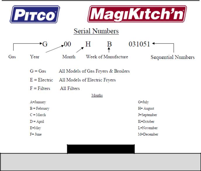
2.1 Serial Numbers
NOTE
If, parts returned to the factory under warranty are found to be a functional/serviceable, Pitco may, at its discretion, decline warranty reimbursement and may charge for replacement parts.
L22-392 R1 |
9 |
Pitco SSHLV (ROV) Gas Fryers
2.2 Safety Information
Before attempting to install, operate or service your unit, read the instructions in this manual thoroughly. Throughout this manual, you will find notations enclosed in shaded boxes similar to the one below.
! DANGER !
Clean up any spilled oil or shortening immediately. Oil or shortening left on the floor creates a slipping hazard that will result in personal injury sustained from falling.
NOTE
NOTE boxes contain especially important information.
! CAUTION !
CAUTION boxes contain information about actions or conditions that may cause or result in a malfunction of your system and/or minor personal injury.
! WARNING !
WARNING boxes contain information about actions or conditions that may cause or result in damage to your system and/or moderate personal injury, and which may cause your system to malfunction.
! DANGER !
DANGER boxes contain information about actions or conditions that may cause or result in serious injury or death to personnel, and which may cause damage to your system and/or cause your system to malfunction.
2.2.1 Installation, Operating, and Service Personnel
Operating information for Pitco equipment has been prepared for use by qualified and/or authorized personnel only, as defined in Section 2.3. All installation and service on Pitco equipment must be performed by qualified, certified, licensed, and/or authorized installation or service personnel, as defined in Section 2.3.2.
2.3 Definitions
2.3.1 Qualified and/or Authorized Operating Personnel
Qualified/authorized operating personnel are those who have carefully read the information in this manual and have familiarized them themselves with the equipment functions, or who have had previous experience and/or training with the operation of the equipment covered in this manual.
2.3.2 Qualified Installation Personnel
Qualified installation personnel are individuals, firms, corporations, and/or companies which, either in person or through a representative, are engaged in and are responsible for the installation of electrical appliances. Qualified personnel must be experienced in such work, be familiar with all electrical
L22-392 R1 |
10 |
Pitco SSHLV (ROV) Gas Fryers
precautions involved, and have complied with all requirements of applicable national and local codes.Qualified Service Personnel
Qualified service personnel are those who are familiar with Pitco equipment and who have been authorized by Pitco Frialator to perform service on the equipment. All authorized service personnel are required to be equipped with a complete set of service and parts manuals, and to stock a minimum amount of parts for Pitco equipment. Failure to use qualified service personnel will void the Pitco warranty on your equipment
2.4 Shipping Damage Claim Procedure
What to do if your equipment arrives damaged:
Please note that this equipment was carefully inspected and packed by skilled personnel before leaving the factory. The freight company assumes full responsibility for safe delivery upon acceptance of the equipment.
1.File Claim for Damages Immediately - regardless of extent of damage.
2.Inspect For and Record All Visible Loss or Damage, and ensure that this information is noted on the freight bill or express receipt and is signed by the person making the delivery.
3.Concealed Loss or Damage- If damage is unnoticed until equipment is unpacked, notify the freight company or carrier immediately upon discovery and file a concealed damage claim. This must be submitted within 15 days of date of delivery. Be sure to retain container for inspection.
PITCO DOES NOT ASSUME RESPONSIBILITY FOR DAMAGE OR LOSS INCURRED IN
TRANSIT.
3 Theory of Operation
SSHLV Series gas fryers utilize a welded, stainless steel fryvat that is directly heated with high efficiency, atmospheric burner tubes. The atmospheric burner tubes eliminate the maintenance heavy and inefficient (over time due to clogging) blowers used in other fryers. Heat tubes provide as much as 80% more surface area for heat transfer than open vat fryers (tubeless), providing faster recovery without scorching the oil. Each tube, four total, is fitted with proprietary, incoloy baffles that are heated by air/gas jet emitted from our patented burners. The baffles transfer heat to the fryvat by means of infrared radiation and conduction plus convection flow from the air/gas jet. The tubular heat also allows for a “cold zone” below the tubes where cooking debris will settle at t temperature much lower than the cooking temperate. The lower temperature prevents the debris from carbonizing and oxidizing the cooking oil prematurely as typically found in non-tube style fryvats. In full-vat units, gas flow to the burners is regulated by one electromechanical gas valve. In split-vat units, each burner bank has its own valve to independently control each vat. All fryers in this series are equipped with 24 V AC gas valve systems, and all are configured with matchless ignition.
3.1 The Matchless Ignition System
An ignition module, mounted behind the gas valve, is connected to an ignitor/pilot assembly between the burners. The ignition module performs three important functions: provides an ignition spark, supplies voltage to the gas valve, and proofs the pilot flame. The module employs a four second time delay circuit (after flame sense) and a signal that activates the gas valve. Two types are currently used: A closed-box design is used in most fryers, but in some fryers built for export, the module is packaged differently. A single “one-spark” module is used on current production full-vat fryers. All dual-vat fryers use two single “one-spark” modules. The ignitor/pilot assembly consists of an igniter, a pilot tube/hood, and a flame sensor.
L22-392 R1 |
11 |
Pitco SSHLV (ROV) Gas Fryers
3.2 Auto Filtration Boards
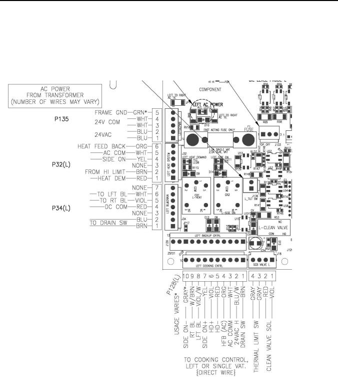
All fryers in this series have an Auto-Filtration Board (AFB) located in the component box behind the control bezel. The AFB provides a “bus” between the controller and the fryer's individual components without requiring additional wiring by using a communication protocol over a twisted pair, and allows the controller to execute commands from one central point. The heat control circuit is show below in Figure 1. This is the bottom left corner of the AFB. For a split vat, this is duplicated on the bottom right hand corner.
Figure 1 - Bottom left corner of Auto Filtration Board
L22-392 R1 |
12 |

Pitco SSHLV (ROV) Gas Fryers
Figure 2 - Auto-Filtration Board (AFB)
L22-392 R1 |
13 |

Pitco SSHLV (ROV) Gas Fryers
3.3 Thermostats
SSHLV Series gas fryers have temperature probes located above and between the third and fourth heat tube of each fryvat (split vat fryers have two probes, one in each vat). SSHLV fryers, like all Solstice series fryers, use a thermistor style temperature probe. In this type of thermostat, the probe resistance varies directly with the temperature. That is, as the temperature rises, so does resistance. Circuitry in the controller monitors the probe resistance and controls burner firing when the resistance exceeds or falls below programmed temperatures (setpoints). SSHLV Series gas fryers are also equipped with a high-limit thermostat. In the event that the fryer fails to properly control the oil temperature, the high-limit thermostat prevents the fryer from overheating to the flash point. The highlimit thermostat acts as a normally closed power switch that opens when exposed to temperatures above 425°F to 450°F (218°C to 232°C).
3.4 Fryer Sequence Operation
The SSHLV fryer components function in specific order of operation. Knowing and understanding the sequence of fryer and components operation enables you to diagnose equipment failure more accurately.
3.5 Heating System
The unit is connected to line voltage:
•If Fuse F1 on the relay board is good:
•The A.C. indicator is illuminated.
•The controller is supplied with 24 VAC.
•With the drain valve handle closed, the proximity switch supplies 24 VAC to the drain valve interlock (DVI) input at the controller.
•24 VAC is at the Side On (SO). relay COM contact.
•The controller is turned ON:
•The SO indicator on the relay board is illuminated.
•The SO relay is energized, closing the circuit.
•With the roll out switch and hi-limit in the closed position, the ignition module receives 24VAC at terminal 6 (24 VAC).
•The ignition module:
•Sends 24 VAC from terminal 3(PV) to the PV terminal on the gas valve.
•Sends the igniter 15kv to spark.
•Senses the flame once the pilot has lit and it sends 24 VAC at terminal 1(MV) and puts 24 VAC at the Heat Demand (HD) relay COM contact on the relay board. The HD relay on the relay board interrupts the 24 VAC supply to the gas valve until the controller calls for heat.
NOTE
When the controller is on, the pilot should always remain lit.
•The controller calls for heat:
• The HD indicator on the relay board is illuminated.
L22-392 R1 |
14 |
Pitco SSHLV (ROV) Gas Fryers
•The HD relay is energized, closing the circuit sending 24 VAC to the MV terminal on the gas valve.
•The computer is supplied with a 24 VAC heat feedback (HFB) signal.
3.6Safety System
When the roll out switch or hi-limit trips, it interrupts the 24 VAC supply to the ignition module.
•When the controller calls for heat, it does not receive a 24 VAC HFB. With approximately 90 seconds of HFB loss, the controller indicates an ignition failure or heat failure.
•After the roll out switch hi-limit is reset, turn the controller off and then back on for the unit to heat.
3.7Filter System (Manual Filtration Only)
Pulling the BLUE drain valve handle will:
•Open the drain at the bottom of the fry vat
•Open the “Drain Valve Interlock” (DVI) magnetic switch disabling the heating system during filtration.
!WARNING!
Inspect the filter pan prior to pulling the BLUE DRAIN VALVE HANDLE to insure it is empty. If the filter pan has visible oil, opening the valve will result in hot oil overflow onto the floor resulting in slipping hazards, fall related injuries, serious burns or death.
•Push handle in to close Drain and enable DVI.
Pulling the RED return valve handle:
•Opens the return valve to that vat.
•Closes the pump proximity switch causing the “pump run” relay to be energized.
•The pump motor begins to run.
•Closing the return valve handle de-energizes the relay and the pump motor stops running and the return valve closes.
•The pump system is equipped with a circuit breaker which de-energizes the system and the heat tape (If equipped) in the event of over current. The circuit breaker must be in the “ON” position for the pump and heat tape to operate.
NOTE
Circuit Breaker should remain in the “ON” position at all times.
Pulling the BROWN waste oil valve will: (If equipped):
•Divert oil flow from the pump to the fry vat to user supplied waste oil plumbing through a Pitco supplied three way valve.
•The return piping system may be provided with optional heat tape to prevent solidification of solid shortening. The heat tape is low wattage and is on constantly to maintain liquid shortening in the line.
L22-392 R1 |
15 |
Pitco SSHLV (ROV) Gas Fryers
3.8 Basket Lift (Optional)
The basket lift is a self contained unit that requires a 120V, 208V, or 240V supply. With most fryer configurations, the power is supplied from the entrance box at the back of the fryer, but some configurations require power directly from a wall outlet.
•When power is supplied to basket lift assembly, the baskets lift to the up position.
•The baskets lower with a 24 VDC output from the controller.
•The basket lift control voltage is supplied from the controller
•The basket lift operational voltage is supplied from the line voltage supply that powers the transformer in the basket lift assembly.
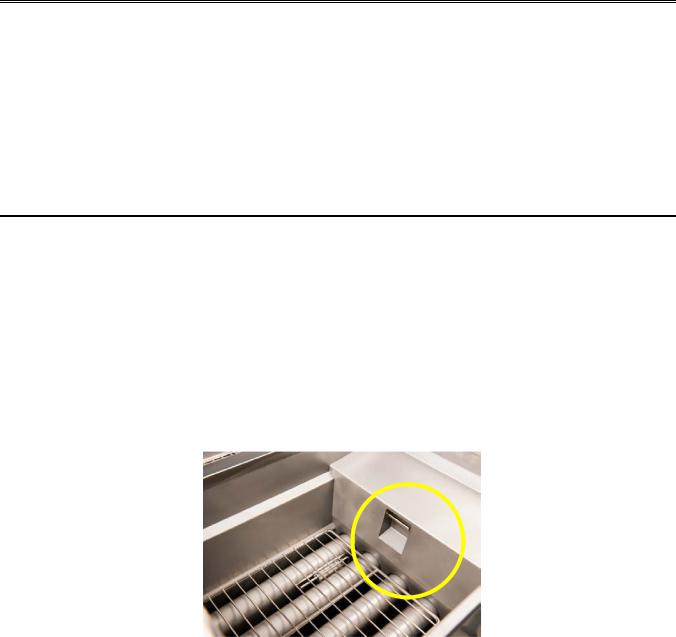
3.9Auto Top Off – ATO (Optional)
•If equipped, the optional Auto Top Off (ATO) adds small doses of oil from the “Jug in Box” or JIB when low oil conditions are detected. During frying, small amounts of oil are absorbed (called “drag out”) by the food and removed from the fryer. These small amounts eventually lead to replenishment with a “Top Off” event.
•The fryer cannot be filled from empty with the Auto Top Off option.
•The ATO uses the filter pump to move oil from the JIB to the fry vat when low oil conditions are sensed. A linear actuator redirects the pump flow from the JIB during a Top Off event.
•The ATO doesn’t not operate during a cook cycle to keep the oil hot during cooking. Adding room temperature oil during cooking would negatively impact the cook cycle and product.
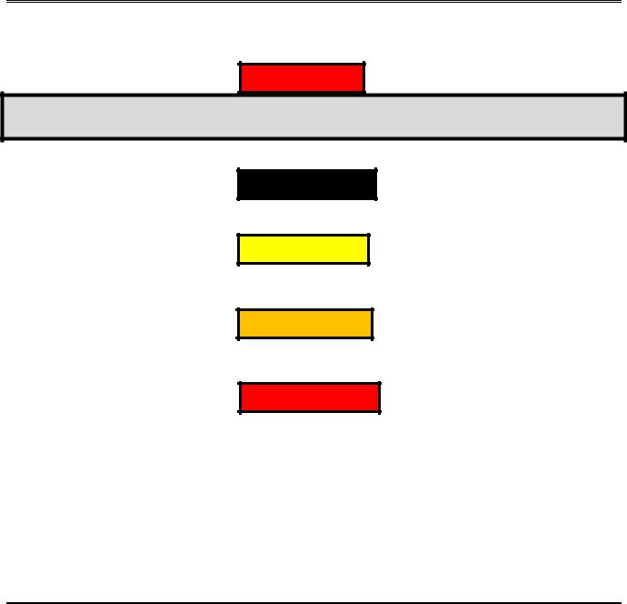
•The ATO probe is located in a reservoir (or weir) at the front, top of the fry tank as pictured above:
•The probe reservoir must be free of debris & food particles to work properly.
•The ATO probe plugs into the Auto Top Off relay board behind the front control bezel. The following conditions must be met for the ATO event to occur:
•The vat must be in idle condition, not cooking or melting, with display showing “Ready” or “Drop”. This display typically shows when the vat is within 20°F of cooking set-point.
•When the cooking control shows Ready, the oil level probe will take time to detect the low level condition. The lower the level the faster the response. The reverse is also true. Modestly low levels take longer to resolve. (< 3/8” below probe). Levels ½” below probe should detect in 3- 1/2 minutes or less.
L22-392 R1 |
16 |
Pitco SSHLV (ROV) Gas Fryers
•Food debris, or oil caked onto probe may prevent ATO operation. Occasional probe cleaning when vat is empty and cool is recommended.
•Top off does not occur when the control is Off, Melting, Cooking, or Heating.
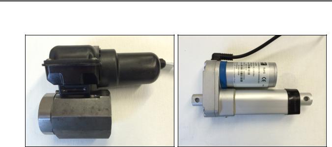
3.10 Automated Filtration (Optional)
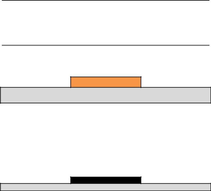
•If equipped with an Automated Filtration system, the filtration works like any other Solstice Fryer except the manual handles (blue and red) are replaced with actuators (show below) to drain the fry vat and return oil to fry vat after filtering.
Drain Valve Actuator (top) with Drain Valve (below) 1 |
Linear Actuator 1 |
•The Automated Filtration system does not actuate “automatically”, user input is required.
•The actuators for the drain valve and return valve can be manually operated through the I12 computer. (See instructions in this manual, Section 6)
•When a pre-determined threshold (typically a user programmed number of cooks) is reached, the operator can be prompted to filter the cooking oil. Upon successful operator input, the system:
•Begins an automated filtration process that first opens the drain valve and drains the oil into the filter pan.
•Shortly after the drain valve opens, the linear actuator opens the return valve and the filter pump actuates. The filtering process operates for a pre-defined period of time (user programmable)
•The drain valve closes and the pump continues to run, returning the freshly filtered oil to the fry vat.
•When all the oil has been pumped back to the fry vat, the pump turns off and the return valve closes.
•The operator is queried to insure the vat is full. If the operator responds “NO”, the filter pump turns on and the return valve is opened to pump any remaining oil from the filter pan. When the operator responds “YES”, the fryer turns itself off and must be re-energized by the operator pressing the “ON” key to restore power and begin frying.
L22-392 R1 |
17 |
Pitco SSHLV (ROV) Gas Fryers
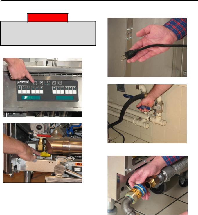
4 Accessing Fryer for Servicing
! DANGER !
Prior to moving, testing, maintaining or repairing your appliance, ensure it is emptied of all oil, cool, disconnected from gas and all electrical power. Failure to do so may result in property damage, damage to your fryer, injury or death.
1. Press off button on control panel.
3. Unplug all power cords.
4. Shut off the main gas supply line to the unit.
5. Pull back collar to remove the quick disconnect gas line.
2. Shut off the individual gas supply line.
L22-392 R1 |
18 |
Pitco SSHLV (ROV) Gas Fryers
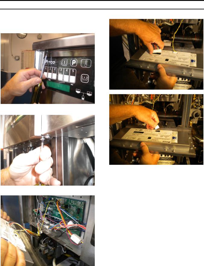
5 Replacing the Controllers
5.1 Removing the Controller Front Panel Bezel
1. Remove the two (2) screws on the controller panel using a Phillips screwdriver. (on a Dual unit you will need to remove the front panel divider).
3. Disconnect the controller wiring harness.
(For a dual unitremove the front panel divider)
2. Pull out the controller panel front bezel.
L22-392 R1 |
19 |
Pitco SSHLV (ROV) Gas Fryers
6 Manual Operation of Drain and Return (Auto Filter Only)
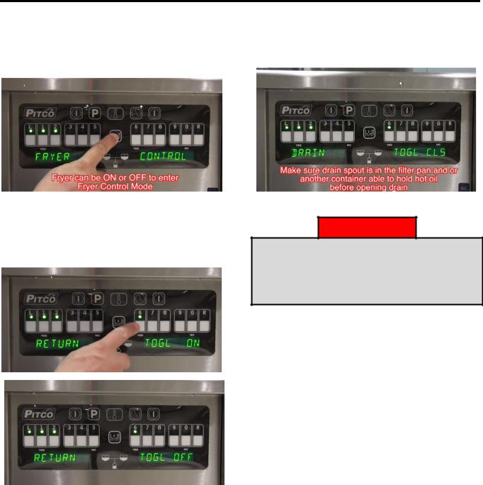
1. To open and/or close drain or return oil from filter pan manually, hold center filter button until display changes to fryer control (can be done with fryer on/off).
3. Pressing the “1” key brings up drain toggle optionpress “YES” to open drain – drain will remain open until “YES” key is pressed again to toggle drain closed.
2. Pressing “L” key brings up the return mode, Pressing “Yes” key activates the motor and allows the pump to return oil from the filter pan to the vat. The pump/motor will remain on until you press “yes” key again to toggle off.
! DANGER !
Any and all spilled oil, water or other liquids that occurs as a result of operation, cleaning, maintenance or repair of this fryer should immediately be cleaned and dried. Failure to do so can create a slippery surface resulting in falling/impact injury or death.
L22-392 R1 |
20 |
Pitco SSHLV (ROV) Gas Fryers
7 Blocked Drain (Auto Filter Only)
1. Display of “Blocked Drainretry”. The drain is not closing and the controller is not receiving the signal that shows that the drain has been closed.
4. If at any time you push “N” (0) key another scrolling message “FRYER WILL BECOME INOPERABLE”, “CONFIRM SHUT DOWN” message.
NOTE
Use ONLY the supplied drain cleaning tool to remove any food debris or foreign object from drain. Use of any other tool can damage your drain valve and will void the warranty.
2. Once you cleared the drain press “YES” button (6) key. If drain closes and the controller receives the correct signal, check the drain again to insure the cleaning tool has been removed. Your fryer should go back into normal mode. If not, your controller will scroll “block drain”. You only have 3 times to try and unblock drain before controller goes into lock out.
3.If after three tries, the drain is still blocked the fryer will no longer operate. If you have a multi fryer system, the other fryers shouldn’t be affected by this error. Contact Pitco Service or Authorized Service Person for assistance. There is NO reset from front controller panel.
5. If you press the “N” (0) key then the message will revert to the display “Blocked Drain” as in number 1. If you press the “Y” (6) key message will display “Call Service – ERR” the fryer will no longer operate. If a multi fryer system the other fryers shouldn’t be effected by this error.
! WARNING !
DO NOT UNPLUG FRYER FROM SUPPLY
POWER. If the unit is unplugged and plugged in again, you WILL damage your drain valve and void the warranty.
L22-392 R1 |
21 |
Pitco SSHLV (ROV) Gas Fryers
7.1 Replacing the Relay Board and Paper
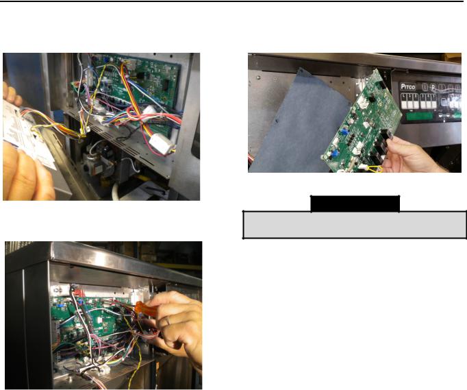
1.Remove the front panel. See “Removing the Controller Front Panel Bezel” in Section 5.1.
2.Disconnect all connections from the board.
5. Remove the existing insulation paper and replace with a new insulator paper.
3. Remove the seven (7) screws, which hold down the relay board, using a small flathead screwdriver.
NOTE
Make sure the insulation paper doesn’t have puncture marks in it.
6. Reinstall by following steps 1 through 5 in reverse.
4. Remove the relay board and flip it over.
L22-392 R1 |
22 |
Pitco SSHLV (ROV) Gas Fryers
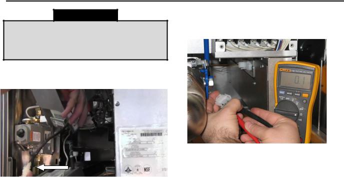
8 Checking Resistance
8.1 Checking the Resistance of the Transformer
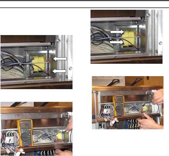
1.Disconnect all electrical power. Remove the front panel (see “Removing the Controller Front Panel Bezel” in Section 5.1).
2.Disconnect the secondary side terminals.
3.Connect the multimeter to the secondary terminals and check the resistance.
4. Disconnect the primary side terminals.
5.Connect the black lead of multimeter to the primary terminal marked “5” and check the resistance readings of taps in following chart on page 24.
Secondary Terminals
.7 ohms +/- 20ohms
L22-392 R1 |
23 |
Pitco SSHLV (ROV) Gas Fryers
8.2 Diagram Identifying Terminals for Second Resistance
PP10429
Secondary Resistance
TAP |
|
Volts |
Resistance |
10 - 6 |
|
24V |
0.7 |
|
|
|
|
|
Primary Resistance |
||
Tap |
|
Volts |
Resistance |
5 - 1 |
|
240V |
30.4 |
5 - 2 |
|
208V |
25.3 |
5 - 3 |
|
120V |
9.9 |
PP10428
Secondary Resistance
|
TAP |
Volts |
Resistance |
|
10 - 6 |
24V |
0.6 |
|
|
||
|
Primary Resistance |
||
|
Tap |
Volts |
Resistance |
|
5 - 1 |
480V |
119.5 |
|
5 - 2 |
440V |
107.7 |
|
5 - 3 |
380V |
90.2 |
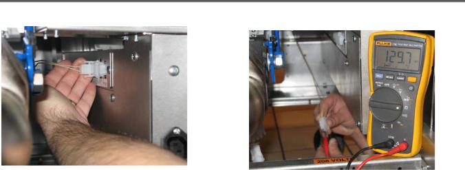
8.3 Checking the Resistance of the DVI Switch
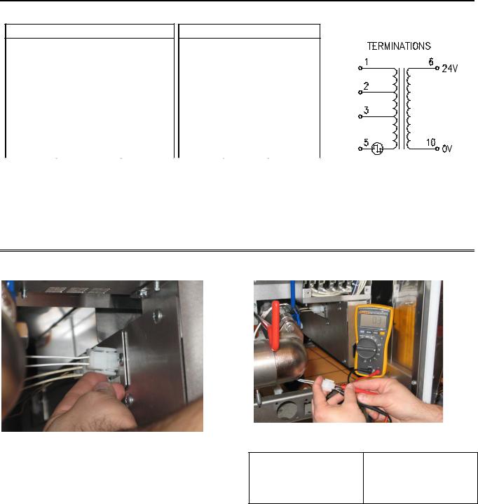
1.Remove the Drain valve interlock (DVI) connection.
2.Connect the multimeter to the DVI leads and check the resistance.
DVI Resistance Table:
Valve Closed |
Valve Open |
|
|
Near Zero Ohm |
Open Circuit |
3.If measurements do not match the tables above, replace the DVI, following instructions in Section 29.
L22-392 R1 |
24 |
Pitco SSHLV (ROV) Gas Fryers
8.4 Checking the Resistance of the Hi-Limit
NOTE
If the Hi-limit is suspect, allow the fryer to cool to room temperature before performing this test. The high limit will remain OPEN until the oil temperature has dropped below the tripping threshold..
1. Unplug the Hi-Limit connection.
2.Connect the multimeter to the Hi-limit leads and check the resistance.
3.If the measurement shows an open circuit and/or greater than 0.5 ohms then the Hilimit is bad and needs to be replaced or reset. see Section 10.
If there is a small resistance
(0.1 – 0.2 ohms) reading, the Hi-limit is closed and ready to use, no replacement is required.
L22-392 R1 |
25 |
Pitco SSHLV (ROV) Gas Fryers
8.5 Checking the Resistance of the Temperature Probe
1. Remove the probe connection.
2.Connect the multimeter to the temperature probe leads and check the resistance.
” See Temperature Probe Resistance Chart on page 84”.
3.If the measurement on the temperature probe does not match the data in the Probe Resistance Chart, the temperature probe must be replaced per instructions in Section 9.
L22-392 R1 |
26 |
Pitco SSHLV (ROV) Gas Fryers
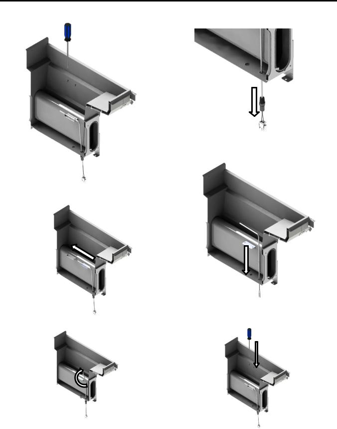
9 Replacing Temperature Probe
1. Remove Phillips screws from probe holder.
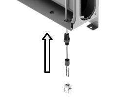
4.Loose compression fitting, pull entire probe out of bottom of tank.
5. Install new probe from top.
2.Slide probe holder off toward the back of the tank.
3. Bend horizontal section of probe straight up.
6.Install probe holder with Phillips screws. (Leave screws loose)
L22-392 R1 |
27 |
Pitco SSHLV (ROV) Gas Fryers
7.Install stuffing block in tank using high temperature food grade thread sealer. Install white housing on terminals. Tighten ferrule nut on stuffing block. Plug connector back in to entrance box (J7/J107). Tighten screws on probe holder.
L22-392 R1 |
28 |
 Loading...