


|
|
US |
|
|
CAN |
|
|
GB |
|
Technical Service and Exploded Parts |
|
|
For Electric Fryers |
|
|
Covering Models |
|
|
MEII, ME2 Full and Split |
|
Pitco Frialator, Inc., |
P.O.Box501,JctI-89&I-93Concord,NH03302-0501•509Route3A,Bow,NH03304 |
|
L22-233 Rev 1 (04/03) |
(800)258-3708•(603)225-6684•FAX(603)225-8497 |
www.pitco.com |

WARNING! FIRE HAZARD
THE OIL LEVEL SHOULD NOT FALL BELOW THE MINIMUM INDICATED LEVEL ATANY TIME. THE USE OF OLD OIL CAN BE DAGEROUS AS IT WILL HAVE A REDUCED FLASH-POINT
AND BE MORE PRONE TO SURGE BOILING.
WARNING
INSTALLATION AND ALL CONNECTIONS MUST BE MADEACCORDING TO NATIONALAND
LOCAL REGULATIONSAND CODES IN FORCE.
WARNING
ACOUNTRYAPPROVED ALL POLE CIRCUIT BREAKER WITH A MINIMUM OPEN CONTACT GAP OF 3mm MUST BE USED FOR PROPER INSTALLATION.
WARNING
THE FRYER IS NOT JET STREAM APPROVED. DO NOT CLEAN THE APPLIANCE WITH A
WATER JET.
NOTICE
INSTALLATION SHOULD ONLY BE DONE BYA COMPETENT SERVICE TECHNICIAN. THE MODEL & SERIAL NUMBER, AND ELECTRICAL REQUIREMENTS STAMPED INTO THE DATA PLATE, LOCATED ON THE INSIDE PANEL OF THE DOOR.
NOTICE
THIS APPLIANCE IS INTENDED FOR PROFESSIONAL USE ONLY, AND AS SUCH, SHOULD
BE OPERATED BY FULLY TRAINED PERSONNEL.
NOTICE
IT IS RECOMMENDED THAT THIS MACHINE BE INSPECTED BYA QUALIFIED TECHNICIAN
ON AYEARLY BASIS.
WARNING
THE POWER SUPPLY MUST BE DISCONNECTED SERVICING OR CLEANING THE UNIT.
WARNING
SHORTENING, WHEN IT ISAT OPERATING TEMPERATURES, IS VERY HOTAND
DANGEROUS! USE EXTREME CAUTION WHEN HANDLING! USE PROPER PROTECTIVE
GEAR SUCH AS INSULATED GLOVES, APRONS, FACE SHIELD, AND SLEEVES WHEN HANDLING HOT SHORTENING. DO NOTATTEMP TO MOVE MACHINE THAT HAS HOT OIL IN IT. ALLOW TO COOLTO ROOM TEMPERATURE OR DRAIN THE OIL INTO A SUITABLE
CONTAINER BEFORE MOVING THE FRYER.
L22-233 Rev 1 (04/03)

US
CAN
GB
Table of Contents |
|
How Does It Work? ........................................................... |
4 |
Component Troubleshooting.............................................. |
4 |
Temperature Probe Resistance Chart ................................. |
4 |
Basic Trouble Shooting ...................................................... |
6 |
Relay Board Component Explanation ................................ |
8 |
Ladder Diagram .................................................................. |
11 |
Schematics ......................................................................... |
12-21 |
Basic Parts List................................................................... |
23 |
Exploded Drawings ............................................................ |
24-33 |
Element and Tank Components ......................................... |
24 |
Pump Box and Drain Manifold........................................... |
26 |
Main Entrance Box ............................................................. |
28 |
Pump Assembly and Filter Pan .......................................... |
30 |
Wire Harness’ ..................................................................... |
32 |
L22-233 Rev 1 (04/03)
Chapter 1: HOW DOES IT WORK?
The McDonalds Electric II fryer components function in specific order of operation. Knowing and understanding the sequence of fryer and components operation will enable you to diagnose equipment failure more accurately.
Heating System
Power to the machine is turned ON:
•If Fuse F1 on the Relay board is good, the A.C. light will illuminate. The computer is supplied with 24VAC and, if the drain valve handle is closed, the proximity switch will supply 24 VAC to the DVI (drain valve interlock) Input at the computer.
•The computer is turned ON:
•The side on relay will be energized, closing the circuit and the S.O. light on the Relay Board will illuminate. If the hi limit is NOT tripped the safety (side on) contactor will energize.
•Computer calls for heat:
•The 24 VDC "heat demand" relay will energize supplying the heat demand contactor with 24 VAC and the H.D. light on the Relay Board will illuminate. This will also supply the computer with a heat feedback signal.
Hi Limit System:
•If the hi limit trips, it causes the side on and heat demand contactors to lose 24VAC supply and the heat feed back loses 24VAC. The computer will display IGNITION FAILURE or HEAT FAIL. After the hi limit resets (unit cools to 375°F + 20°F) the computer will have to be turned off and back on for the unit to heat.
proximity switch causing the "pump run" relay to be energized. The pump motor will begin to run. Closing the return valve handle will de-energize the relay and the pump motor will stop running.
•The pump system is equipped with a circuit breaker which will de-energize the system and the heat tape in the event of overcurrent. The circuit breaker switch must be in the ON position for the pump and heat tape to operate.
•The return piping system may be provided with optional heat tape to prevent solidification of solid shortening. The heat tape is low wattage and is on constantly to maintain liquid shortening in the line.
Chapter 2: COMPONENT
TROUBLESHOOTING:
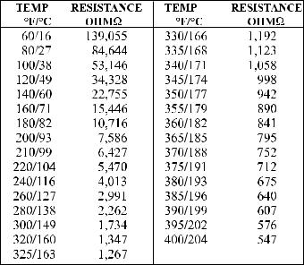
Probe:
Hood Relay System: U.S./Canada units only
•There is one Hood Relay (K6) per "battery" of fryers (located on rear bottom brace of left hand fryer), it is wired in parallel to every computer (both sides of a twin). When any side of any computer is turned on this relay energizes (turning on the hood) and will stay energized until all of the computers are turned off.
Filter System:
•Opening the RED return valve handle will close the
The resistance of the probe will change as the temperature changes. The resistance will decrease as the temperature rises. The lower the temperature the greater the resistance change will be per degree of temperature change, as the temperature approaches the working range of the probe, the resistance change will become more linear.
If the probe is suspect, check its resistance and the oil/ air temperature at which it was taken. Compare these
L22-233 Rev 1 (04/03) |
4 |

values on the chart below.
If the probe returns an open circuit or 0 Ohms reading it should be replaced. If the resistance varies more than 30 Ohms when being checked between 325-375°F the probe will give a false temperature reading on the computer and should be calibrated (up to 10°F) or replaced. However, it will continue to operate at a slightly higher or lower temperature.
Allow the oil to cool and check the probe resistance at a lower temperature. As can be seen from the chart a greater variation can be tolerated at a lower temperature.
Heat Demand Contactor:
The heat demand contactor has a 24VAC coil and will energize when the correct voltage is supplied to the coil. When energized, the contacts will close, allowing current to flow through the elements. The coil resistance is 192 ohms out of circuit.
Hi Limits:
The hi - limit switch is a normally closed switch until the temperature at the hi-limit bulb reaches 425°F ± 20°F.
In order to test this switch it will be necessary to utilize the temperature control hi-limit feature. Refer to PM Card FR015 for instructions on how to perform this test.
WARNING
During this test monitor the fryer closely. This test will cause the oil to heat past the normal operating temperature and can cause damage to the machine and its operator if care is not taken.
If the switch does not trip between the prescribed limits it is defective and should be replaced. Once tripped, the switch cannot be reset until the oil has cooled to approximately 375°F + 20°F. If the switch does not reset after oil has cooled it is defective. Once the oil has cooled the hi-limit reset button must be pressed to reset the hi-limit relay on CE and export unitsonly.
US
Drain Valve & Return Valve Switches: CAN GB
These switches are a magnetically operated proximity switches. When the Drain Valve handle is moved to the open position, theActuator will move away from the switch causing the switch to open. When the Drain Valve is closed the switch will close.
Opening the RED return valve handle will close the proximity switch causing the "pump on" relay to be energized. The pump will begin to pump. Closing the return valve handle will de-energize the relay and the pump will stop pumping. These switches can also be checked with an Ohm meter. The normal gap between theActuator and the Sensor switch on the valve handle is 1/8" - 1/4" (3 - 6mm).
Transformer:
Transformers are multiple input voltage 24 volt output voltage and can be checked by reading the input and output voltages.Aquick check for 24VAC can be done at the relay board behind the computer. TheAC led will be lit if the F1 fuse is good and the board is receiving 24VAC
Elements:
Each Element has three coils inside it, check all element coils out of circuit with an Ohm Meter, the resistance should correspond to the chart below, if the resistance varies more than 5 Ohm the element will need to be changed. Also check for continuity to ground on each end of the suspect element, there should be no continuity to ground.
208 volt elements |
18.5 Ohms |
220 volt elements |
20.7 Ohms |
240 volt elements |
24.6 Ohms |
Safety (Side On) Contactor:
Check the coil with an Ohm Meter, the resistance should be approximately 3 - 6 Ohms out of circuit. If it does not have this resistance it should be changed.
5 |
L22-233 Rev 1 (04/03) |
Fryer Trouble Shooting
PROBLEM |
POSSIBLE CAUSE |
ACTION |
Computer will NOT turn ON |
A. No power to the machine |
A. Check building circuit breaker, verify |
Display does NOT light |
B. F1 Fuse blown |
power cord is plugged in |
|
C. T1A Transformer |
B. Check F1A Fuse. Replace if defective |
|
|
C. Check voltage in and out of T1A |
|
|
|
Computer shows "IGNITION |
A. Hi limit tripped |
A. Once the oil temp has gone below |
FAILURE" or "HEAT FAIL" and |
B. Heat demand relay |
375°F + 20°, the Hi-limit should reset |
machine does NOT heat. |
C. Relay board |
automatically, if not, replace Hi-limit |
|
|
B. Check & replace if defective |
|
|
C. Check & replace if defective |
|
|
|
Machine is heating slowly |
A. Side On contactor |
A. Check & replace if defective |
|
B. Heat Demand contactor |
B. Check & replace if defective |
|
C. Element |
C. Check & replace if defective |
|
D. Loss of power on one leg of 3 |
D. Check input power. Repair or call a |
|
phase input power |
qualified electrician |
|
|
|
Oil is hotter or colder than computer |
A. Temperature calibration |
A. Adjust temperature offset up to +10°F |
/controller displays |
B. Probe |
B. Check & replace if defective |
|
C. Probe wiring terminals |
C. Clean or repair terminals |
|
|
|
Computer displays "DRAINING" or |
A. Blue drain valve not fully closed |
A. Check position of handle |
"TURN OFF" |
B. Sensor switch |
B. Switch may be loose or have loose |
|
C. Incorrect switch gap/alignment |
wires, replace if defective |
|
|
C. Check gap/alignment, replace if defective |
|
|
|
Computer heat demand lights are lit, |
A. Side on contactor |
A. Check & replace if defective |
machine does not heat. HD & SO |
B. Heat demand contactor |
B. Check & replace if defective |
lights on relay board are lit. |
C. Unit not getting 3 phase power |
C. Check circuit breaker, is 3 phase power |
|
|
cord plugged in all the way |
|
|
|
Computer displays "PROBE |
A. Shorted probe |
A. Check probe & replace if defective |
FAILURE" |
B. Open probe |
B. Check probe & replace if defective |
|
C. Probe wiring terminals |
C. Clean or repair terminals |
|
|
|
L22-233 Rev 1 (04/03) |
6 |

Filter Trouble Shooting
US
CAN
GB
PROBLEM |
POSSIBLE CAUSE |
ACTION |
|
|
|
Red return handle is pulled out, but no |
A. Red return handle not completly |
A. Pull on red return handle to make sure |
pump sound can be heard |
open |
valve is completly open |
|
B. Filter circuit breaker may be tripped |
B. Reset the circuit breaker or press it to |
|
or in the off position |
the on position |
|
C. Filter motor thermal overload may |
C. Push the red reset button on the end of |
|
be tripped |
the motor |
|
D. Sensor switch may be loose or |
D. Check that the switch is tight and that it |
|
defective |
has the correct gap. Replace if defective |
|
E. Power cord unplugged or loose |
E. Check the power cord at the fryer |
|
|
entrance box and at the pump box and |
|
|
make sure that the power cords are plugged |
|
|
in and /or pushed in all the way |
|
|
|
Drain valve is closed, computer has |
A. Blue drain valve not fully closed |
A. Check position of handle |
been reset, but computer still displays |
B. Sensor switch |
B. Switch may be loose or have loose |
"DRAINING" |
C. Incorrect switch gap/alignment |
wires, replace if defective |
|
|
C. Check gap/alignment, replace if defective |
|
|
|
Oil is returning to the vat slowly or not |
A. Dirty filter paper |
A. Change filter paper |
at all |
B. Strainer cap dirty |
B. Remove strainer cap and clean it |
|
C. Filter pan not pushed in completely |
C. Push filter pan in |
|
D. O-rings not sealing on pick up tube |
D. Check & replace if defective |
|
|
|
Air bubbles are in the oil being returned |
A. Strainer cap not tight |
A. Tighten strainer cap |
to the vat |
B. Stainer cap not in pick up tube |
B. Install strainer cap |
|
C. Filter pan not pushed in completely |
C. Push filter pan in |
|
D. O-rings not sealing on pick up tube |
D. Check & replace if defective |
|
|
|
Drain valve is open, the oil is draining |
A. Drain valve is not fully open |
A. Apply a little more pressure to the drain |
slowly or not at all |
B. Drain line is plugged with debris |
valve handle to check that the drain valve is |
|
|
fully open |
|
|
B. Use the clean out rod to clear the drain |
|
|
valve opening. If this does not clear the |
|
|
blockage, close the drain valve, and call for |
|
|
service |
|
|
|
7 |
L22-233 Rev 1 (04/03) |
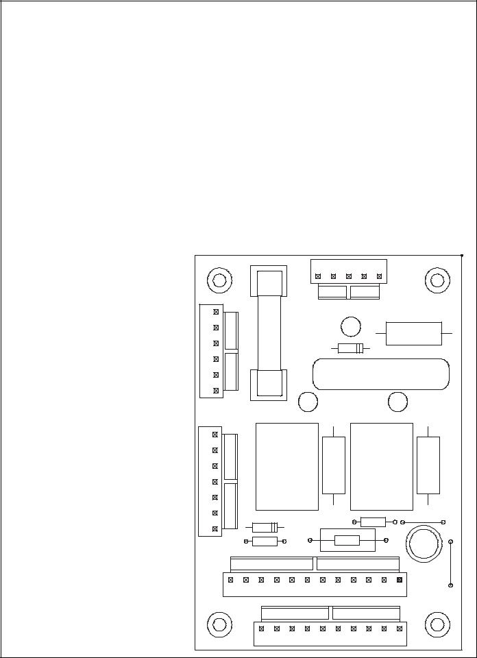
Relay Board Component Explanation
Fuse:
F1 - If fuse is blown, A.C. will not be lit.
Trouble Shooting Lights:
A.C. - When lit, F1 Fuse and T1 Transformer are good.
S.O. - When lit, A1 Computer is on and K10 Contactor should be energized.
H.D. - When lit, A1 Computer is on and calling for heat, K11 Contactor should be energized
Relays:
K1 - Heat Demand Relay, will be energized when A1 Computer calls for heat and when H.D. is lit. K3 - Side On Relay, will be energized when A1 Computer is on and A.C. is lit.
Connectors:
J31 - Connects to A1 Computer
J32 - To Side On and Heat Demand Contactors and Heat Feed Back. J33 - To 24VAC jumper harness.
J34 - To Drain Switch and optional Basketlifts
J35 - Input voltage from transformer
6 |
|
J32 |
FUSE |
F1 |
|
1 |
|
7
K1
J34 HEAT
DEM
1 J35 5
A.C.
PITCO# 60127301A
DATE: MMDDYY
H.D. S.O.
K3
SIDE
ON
1
12 |
J33 |
1 |
10 |
J31 |
1 |
L22-233 Rev 1 (04/03) |
8 |
|
|
|
24VAC FROM A CLASS 2 |
|
|
|
J33 |
|
||
|
|
|
TRANSFORMER |
|
|
|
|
|
||
|
|
|
|
|
|
|
|
|
||
|
|
|
|
|
|
|
12 |
|
NONE |
|
|
|
|
|
|
|
|
|
NONE |
|
|
|
|
|
|
|
|
|
11 |
|
|
|
|
|
|
|
|
|
|
|
24VAC POWER SWITCHED |
|
|
|
|
1 |
2 |
3 |
4 |
5 |
10 |
|
|
|
|
|
J35 |
|
|
|
|
9 |
|
NONE |
TO |
|
|
|
|
|
|
|
|
NONE |
BACK-UP |
|
|
|
|
|
|
|
|
8 |
|
||
|
|
|
|
|
|
|
|
HEAT DEMAND |
TEMPERATURE |
|
|
|
24VAC |
|
|
|
24VCOM |
6 |
|
||
|
|
FUSE |
|
|
|
|
7 |
|
SIDE ON |
CONTROL (OPT) |
|
|
|
|
|
|
5 |
|
DC RETURN |
OR NO OPTION |
|
|
|
|
|
|
|
|
|
|||
|
|
F1 |
|
|
|
|
4 |
|
HEAT FEED BACK |
JUMPER BLOCK |
|
|
|
|
|
|
2 |
|
24VACH POWER |
|
|
|
|
|
|
|
|
|
|
|
||
|
|
J34 |
|
AC POWER |
|
3 |
|
24VACN RETURN |
|
|
|
|
|
|
|
|
|
||||
|
TO DRAIN |
|
|
|
|
|
DRAIN OR FLOAT SWITCH |
|
||
|
1 |
|
|
|
|
1 |
|
|
||
|
OR FLOAT |
|
|
|
|
|
|
|
|
|
|
|
|
|
|
|
SIDE ON |
|
|
|
|
|
SWITCH |
|
|
|
|
|
|
|
|
|
|
2 |
|
|
|
|
|
|
|
|
|
|
|
|
|
|
|
|
K3 |
|
J32 |
|
|
|
|
|
|
|
|
HEAT DEM |
|
|
|
|
|
|
|
|
|
|
|
|
|
|
|
DRAIN OR |
|
60127301 |
|
|
|
1 |
HEAT DEMAND |
|
|
|
1 |
|
|
|
|
K1 |
|
|
||
|
FLOAT SWITCH |
|
|
|
|
|
HEAT DEMAND ENABLE |
|
||
9 |
|
|
|
|
|
SIDE ON |
|
|
||
24VAC RETURN |
3 |
|
|
|
|
2 |
|
|||
|
|
|
|
K3 |
|
|
||||
|
|
|
|
|
|
|
|
|||
|
|
|
|
|
|
|
|
|
|
|
|
24VACH |
2 |
|
|
|
|
|
|
TO RESET SWITCH IF REQUIRED |
|
|
|
|
|
|
|
|
|
3 |
|
|
|
|
|
|
|
|
|
HEAT |
|
|
|
|
HEAT FEEDBACK |
4 |
|
|
|
|
|
TO HIGH LIMIT |
|
|
|
|
|
|
|
DEMAND |
4 |
|
|||
|
|
|
|
|
|
|
|
|
||
TO |
HEAT DEMAND |
6 |
|
|
|
|
K1 |
|
24VAC RETURN |
|
PRIMARY |
(DC) |
|
|
|
|
|
|
5 |
|
|
J31 |
|
|
|
|
|
|
|
|||
COOKING |
|
|
|
|
|
|
6 |
HEAT FEED BACK |
|
|
CONTROLLER |
|
|
|
|
|
|
|
|
|
|
|
|
|
|
|
|
|
|
|
|
|
|
NONE |
10 |
|
|
|
|
|
|
J34 |
|
|
|
|
|
|
|
|
|
|
|
|
|
SIDE ON (DC) |
7 |
|
|
|
|
3 |
|
|
|
|
|
|
|
|
|
|
|
|
||
|
24VDC RETURN |
5 |
|
|
|
|
|
4 |
DC COMMON |
J34 |
|
|
|
|
|
|
|
|
|
TO BASKET |
|
|
BASKET LIFT L |
8 |
|
|
|
|
|
|
BASKET LIFT LEFT |
|
|
|
|
|
|
|
5 |
LIFT OPTION |
|||
|
|
|
|
|
|
|
|
|
||
|
BASKET LIFT R |
9 |
|
|
|
|
|
6 |
BASKET LIFT RIGHT |
|
|
|
|
|
|
|
|
|
|
|
|
|
|
|
|
|
|
|
7 |
|
|
|
233-L22 |
|
|
|
|
Rev |
Relay Board |
|||
(04/03) 1 |
||||
|
|
|
||
|
US CAN GB |
|
||
|
|
|
|
|
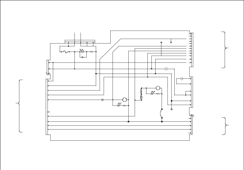
Schematics
L22-233 Rev 1 (04/03) |
10 |
1 |
2 |
3 |
|
4 |
5 |
6 |
7 |
|
|
DRAIN |
|
|
|
|
|
|
|
SWITCH |
|
|
|
|
A |
|
|
NO |
|
|
|
|
|
|
|
NC |
|
|
|
|
|
|
|
|
|
|
|
|
B |
|
24 VAC |
DVI |
24 VAC |
PROBE |
HEAT |
|
|
|
INPUT |
INPUT |
COMMON |
INPUT |
FEEDBACK |
|
|
|
|
|
|
|
|
INPUT |
|
|
|
ON/OFF |
|
|
HEAT DEMAND |
|
|
|
|
(SIDE ON) |
|
24 VDC |
|
||
|
|
OUTPUT |
|
COMMON |
OUTPUT |
|
C |
|
|
SO |
|
|
HD |
|
|
|
|
|
|
|
|
HEAT |
D |
|
|
|
|
|
|
DEMAND |
|
|
|
|
|
|
|
|
|
|
|
|
|
RELAY BOARD |
|
CONTACTOR |
|
|
|
|
|
|
|
|
|
|
|
SIDE ON |
|
|
HEAT |
|
|
|
|
|
|
DEMAND |
|
|
|
|
|
|
|
|
|
|
|
|
|
|
|
|
|
|
E |
|
|
AC |
|
|
|
SIDE ON |
|
|
|
F1 FUSE |
|
|
|
||
|
VAC 24 COMMON |
|
|
CONTACTOR |
|
||
|
|
|
|
|
|
||
|
24 VAC + |
|
|
|
|
||
|
|
|
|
|
F |
||
|
TRANSFORMER |
|
|
|
|
||
|
|
|
|
|
|
||
|
|
|
|
|
HI LIMIT |
|
|
|
|
|
|
|
SWITCH |
|
|
|
|
|
|
|
(DOMESTIC |
|
|
|
|
|
|
|
ONLY) |
|
|
|
TO TRANSFORMER |
|
|
NO |
|
|
|
|
VAC 24 COMMON |
|
+VAC 24 |
|
NC |
|
G |
|
|
|
TO HI LIMIT |
||||
|
|
|
SWITCH |
||||
|
|
|
|
|
CONNECTOR |
|
|
|
|
HI LIMIT |
RESET |
|
|
H |
|
|
|
|
|
|
|
|
|
|
|
|
|
|
|
|
I |
|
|
|
|
|
|
|
J |
|
|
|
|
CE/EXPORT ONLY |
|
|
|
1 |
2 |
3 |
|
4 |
5 |
6 |
7 |
|
|
|
|
11 |
|
L22-233 Rev 1 (04/03) |
|
 Loading...