


IMPORTANT FOR FUTURE REFERENCE
Please complete this information and retain this manual for the life of the equipment:
Model #: ___________________________
Serial #: ___________________________
Date Purchased: ____________________
Exploded Parts Manual
ENGLISH
MODELS |
LJ-FBG18 |
LJ-FBG24 |
LJ-FBGD14 |
LJ-FBGD18 |
L22-297 Rev 0 (06/06) |

Exploded Parts-FBG Gas Models for
Long John Silver’s
Post in a prominent location the instructions to be followed in the event that an operator smells gas. Obtain this information from your local gas supplier.
WARNING
DO NOT store or use gasoline or other flammable vapors and liquids in the vicinity of this or any other appliance.
WARNING
Improper installation, alteration, service or maintenance can cause property damage, injury or death. Read the installation, operating and maintenance instructions thoroughly before installing or servicing this appliance.
WARNING
Installation, maintenance and repairs should be performed by a Pitco Authorized Service and Parts (ASAP) company technician or other qualified personnel. Installation, maintenance or repairs by unauthorized or unqualified personnel will void the warranty.
WARNING
Installation and all connections must be made according to national and local regulations and codes in force.
WARNING
During the warranty period if a customer elects to use a nonoriginal part or modifies an original part purchased from Pitco and/or its Authorized Service and Parts (ASAP) companies, this warranty will be void. In addition, Pitco and its affiliates will not be liable for any claims, damages or expenses incurred by the customer which arises directly or indirectly, in whole or in part, due to the installation of any modified part and/or received from an unauthorized service center.
WARNING
This appliance, when installed, must be electrically grounded in accordance with local codes, or in the absence of local codes, with the National Electrical Code, ANSI/NFPA 70, or the Canadian Electrical Code, CSA C22.2, as applicable.
WARNING
Adequate means must be provided to LIMIT the movement or this appliance without depending on the gas or electrical cord connection. Single appliances equipped with legs must be stabilized by installing anchor straps. All appliances equipped with casters must be stabilized by installing restraining chains.
WARNING
An appliance equipped with casters and a flexible gas line must be connected to the gas supply with a quick disconnect device. This quick disconnect must comply with ANSI Z24.41.
WARNING
DO NOT alter or remove structural material on the appliance to accommodate placement under a ventilation hood.
WARNING
This appliance is intended for professional use only and should be operated by fully trained and qualified personnel.
WARNING
If the appliance is equipped with a power cord and it is damaged, it must be replaced by a Pitco Authorized Service and Parts (ASAP) company technician, or a similarly qualified person in order to avoid a hazard.
WARNING
The power supply must be disconnected before servicing, maintaining or cleaning this appliance.
WARNING
The appliance is NOT jet stream approved. DO NOT clean the appliance with a water jet.
WARNING
DO NOT attempt to move this appliance or transfer hot liquids from one container to another when the unit is at operating temperature or filled with hot liquids. Serious personal injury could result if skin comes in contact with the hot surfaces or liquids.
WARNING
DO NOT sit or stand on this appliance. The appliance’s front panel, tank, splash back, tank cover, workshelf, drain board is not a step. Serious injury could result from slipping, falling or contact with hot liquids.
WARNING
NEVER use the appliance as a step for cleaning or accessing the ventilation hood. Serious injury could result from slips, trips or from contacting hot liquids.
WARNING
The oil/shortening level should NOT fall below the minimum indicated level line at any time. The use of old shortening can be dangerous as it will have a reduced flash point and be more prone to surge boiling.
WARNING
The particles, crumbs and cracklings from the crumb tray/catch (if supplied) in a filtering system must be emptied into a fireproof container at the end of the frying operation each day. Some food particles can spontaneously combust into flames if left soaking in certain oil/shortening materials.
WARNING
Completely shut the appliance down when shortening/oil is being drained from the appliance. This will prevent the appliance from heating up during the draining and filling process. Serious injury can occur.
WARNING
This appliance is intended for indoor use only.
WARNING
DO NOT operate appliance unless all panels and access covers are attached correctly.
WARNING
It is recommended that this appliance be inspected by a qualified service technician for proper performance and operation on a yearly basis.
WARNING
There is an open flame inside this appliance. The unit may get hot enough to set nearby materials on fire. Keep the area around the appliance free from combustibles.
WARNING
DO NOT supply the appliance with a gas that is not indicated on the data plate. If you need to convert the appliance to another type of fuel, contact your dealer.
WARNING
DO NOT use an open flame to check for gas leaks!
WARNING
If gas flow to appliance is interrupted, or pilots extinguish, wait 5 minutes before attempting to relight the pilot to allow any residual gas in appliance to dissipate.
WARNING
Ensure that the appliance can get enough air to keep the flame burning correctly. If the flame is starved for air, it can give off a dangerous carbon monoxide gas. Carbon monoxide is a clear odorless gas that can cause suffocation.
2 |
L22-297 Rev 0 (06/06) |

|
Exploded Parts-FBG Gas Models for |
|
Long John Silver’s |
|
TABLE OF CONTENTS |
FRYER EXPLODED VIEW .............................................................................................................................. |
4 |
FRYER EXPLODED VIEW PARTS LIST .............................................................................................................................................................................. |
4 |
FRYER EXPLODED VIEW ................................................................................................................................................................................................ |
5 |
A) TANK .......................................................................................................................................................... |
6 |
TANK DRAWING A PARTS LIST ....................................................................................................................................................................................... |
6 |
TANK DRAWING A ......................................................................................................................................................................................................... |
7 |
B) TANK JACKET EXTERNAL ....................................................................................................................... |
8 |
TANK JACKET EXTERNAL DRAWING B PARTS LIST........................................................................................................................................................... |
8 |
TANK JACKET EXTERNAL DRAWING B............................................................................................................................................................................. |
9 |
C) TANK JACKET INTERNAL ...................................................................................................................... |
10 |
TANK JACKET INTERNAL DRAWING C PARTS LIST.......................................................................................................................................................... |
10 |
TANK JACKET INTERNAL DRAWING C............................................................................................................................................................................ |
11 |
D) DRAIN LINE.............................................................................................................................................. |
12 |
DRAIN LINE DRAWING D PARTS LIST ............................................................................................................................................................................ |
12 |
DRAIN LINE DRAWING D .............................................................................................................................................................................................. |
13 |
E) ENTRANCE BOX...................................................................................................................................... |
14 |
ENTRANCE BOX DRAWING E PARTS LIST...................................................................................................................................................................... |
14 |
ENTRANCE BOX DRAWING E........................................................................................................................................................................................ |
15 |
F) FRYER CABINET ..................................................................................................................................... |
16 |
FRYER CABINET DRAWING F PARTS LIST ..................................................................................................................................................................... |
16 |
FRYER CABINET DRAWING F........................................................................................................................................................................................ |
17 |
G) RETURN LINE.......................................................................................................................................... |
18 |
RETURN LINE DRAWING G PARTS LIST......................................................................................................................................................................... |
18 |
RETURN LINE DRAWING G........................................................................................................................................................................................... |
19 |
H) PUMP ASSEMBLY ................................................................................................................................... |
20 |
PUMP ASSEMBLY DRAWING H PART LIST ..................................................................................................................................................................... |
20 |
PUMP ASSEMBLY DRAWING H...................................................................................................................................................................................... |
21 |
I) PUMP BOX ................................................................................................................................................ |
22 |
PUMP BOX DRAWING I PARTS LIST .............................................................................................................................................................................. |
22 |
PUMP BOX DRAWING I ................................................................................................................................................................................................ |
23 |
J) CONTROL BOX/FRONT PANEL .............................................................................................................. |
24 |
CONTROL BOX/FRONT PANEL DRAWING J PARTS LIST .................................................................................................................................................. |
24 |
CONTROL BOX/FRONT PANEL DRAWING J .................................................................................................................................................................... |
25 |
K) FILTER PAN ............................................................................................................................................. |
26 |
FILTER PAN DRAWING K PARTS LIST............................................................................................................................................................................ |
26 |
FILTER PAN DRAWING K.............................................................................................................................................................................................. |
27 |
L) IN LINE CRUMB DUMP ............................................................................................................................ |
28 |
IN LINE CRUMB DUMP DRAWING L PARTS LIST ............................................................................................................................................................. |
28 |
IN LINE CRUMB DUMP DRAWING L................................................................................................................................................................................ |
29 |
M) ACCESSORIES........................................................................................................................................ |
30 |
ACCESSORIES DRAWING M PARTS LIST ....................................................................................................................................................................... |
30 |
ACCESSORIES DRAWING M ......................................................................................................................................................................................... |
31 |
L22-297 Rev 0 (06/06) |
3 |

Exploded Parts-FBG Gas Models for
Long John Silver’s
FRYER EXPLODED VIEW
|
|
Fryer Exploded View Parts List |
|
|
|
|
|
ITEM# |
PART# |
PART DESCRIPTION |
|
1 |
60125801 |
SCREW 10 - 24 X 3/8 TRUSS HEAD STAINLESS SLOTTED |
|
2 |
A4109302-C |
SPLASH BACK FLUE SHIELD FBG18 CANOPY HOOD |
|
A4109304-C |
SPLASH BACK FLUE SHIELD FBG24 CANOPY HOOD |
||
|
|||
3 |
P0075400 |
SCREW 10 - 24 X 1/2 SELF TAP |
|
4 |
A1908702-C |
CHANNEL STRIP JOINING FBG TO FBG |
|
A1908704-C |
CHANNEL STRIP JOINING FBG TO SG |
||
|
|||
|
B3634901 |
FRONT PANEL TOP DECK FBG18 |
|
|
B3634902 |
FRONT PANEL TOP DECK FBG24 |
|
|
B3634903 |
FRONT PANEL TOP DECK FBG24-2 |
|
|
B3634904 |
FRONT PANEL TOP DECK FBG18-2 |
|
|
B3634905 |
FRONT PANEL TOP DECK FBG18/24 |
|
|
B3634906 |
FRONT PANEL TOP DECK FBG18/24-2 |
|
5 |
B3634907 |
FRONT PANEL TOP DECK SG14FBG |
|
B3634908 |
FRONT PANEL TOP DECK SG18FBG |
||
|
|||
|
B3634909 |
FRONT PANEL TOP DECK SG14FBG/FBG18 |
|
|
B3634910 |
FRONT PANEL TOP DECK SG14FBG/FBG24 |
|
|
B3634911 |
FRONT PANEL TOP DECK SG18FBG/FBG18 |
|
|
B3634912 |
FRONT PANEL TOP DECK SG18FBG/FBG24 |
|
|
B3634913 |
FRONT PANEL TOP DECK SG14FBG-2 |
|
|
B3634914 |
FRONT PANEL TOP DECK SG18FBG-2 |
|
6 |
60113401 |
CAP 3/4 NPT |
|
7 |
P7037350 |
NIPPLE 3/4 NPT CLOSE BLACK IRON |
|
8 |
P7037350 |
NIPPLE 1 NPT CLOSE BLACK IRON |
|
9 |
P7036970 |
REDUCER COUPLING 1 NPT X 3/4 NPT |
|
|
B8040101 |
REAR TEE MANIFOLD WELDMENT DUAL |
|
|
B8040102 |
REAR TEE MANIFOLD WELDMENT FBG24-3 OR FBG18/FBG24-2 |
|
|
B8040103 |
REAR TEE MANIFOLD FBG18-3 OR 24/18-2 OR 24-2/18 OR 18/24/18 |
|
|
B8040104 |
REAR TEE MANIFOLD WELDMENT FBG24/18/24 OR 18-2/24 |
|
|
B8040105 |
REAR TEE MANIFOLD WELDMENT FBG18/SG OR FBG24/SG |
|
10 |
B8040106 |
REAR TEE MANIFOLD WELDMENT SG/FBG18 |
|
B8040107 |
REAR TEE MANIFOLD WELDMENT SG/FBG24 |
||
|
|||
|
B8040108 |
REAR TEE MANIFOLD WELDMENT FBG DUAL/SG |
|
|
B8040109 |
REAR TEE MANIFOLD WELDMENT SG/FBG18/FBG24 |
|
|
B8040110 |
REAR TEE MANIFOLD WELDMENT SG/FBG24-2 |
|
|
B8040111 |
REAR TEE MANIFOLD WELDMENT SG/FBG18-2 |
|
|
B8040112 |
REAR TEE MANIFOLD WELDMENT SG/FBG24/FBG18 |
|
11 |
P7036904 |
UNION 3/4 NPT BLACK IRON |
|
12 |
PP10479 |
PLUG 1-1/4 NPT HEX HEAD BLACK IRON |
|
13 |
60134201 |
EYEBOLT 1/4 - 20 FULL THREAD (PART OF GAS HOSE KIT) |
|
14 |
P0093300 |
NUT 1/4 - 20 KEP HEX |
|
15 |
P0007300 |
SCREW 8 - 32 X 1/4 HEX HEAD |
|
16 |
A7021102 |
FILTER PAN COVER |
|
17 |
P6071516 |
CHROME HANDLE 3" |
4 |
L22-297 Rev 0 (06/06) |

Exploded Parts-FBG Gas Models for
Long John Silver’s
Fryer Exploded View
L22-297 Rev 0 (06/06) |
5 |

Exploded Parts-FBG Gas Models for
Long John Silver’s
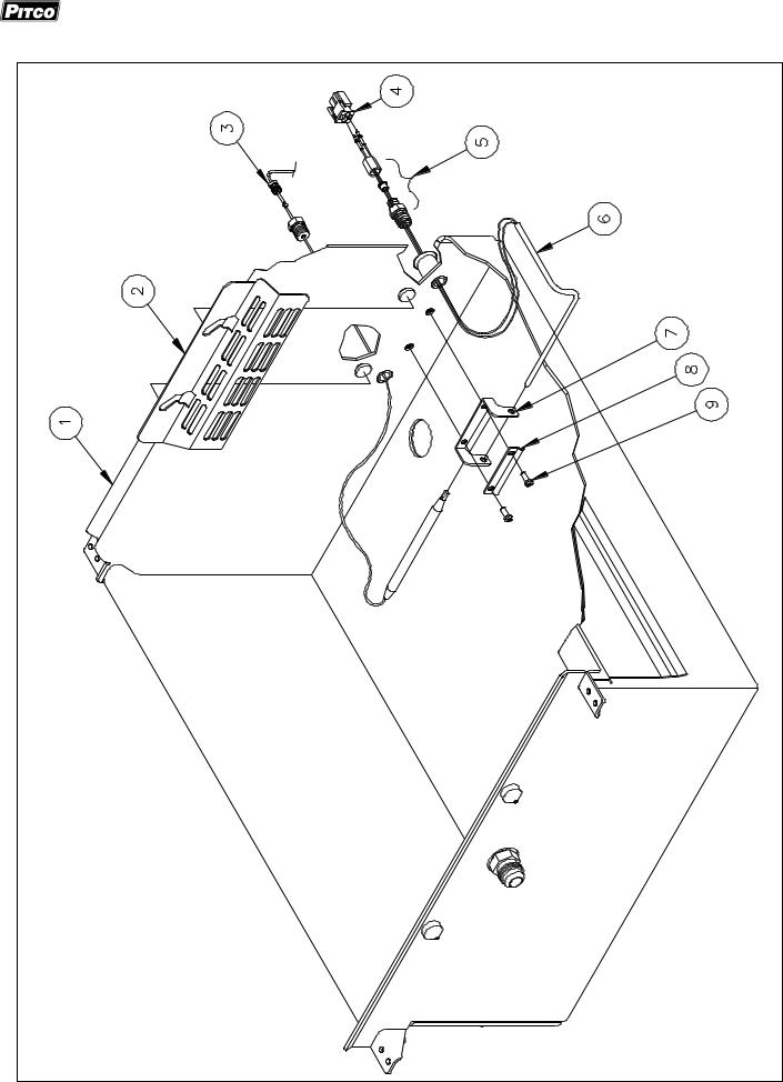
A) TANK
|
|
Tank Drawing A Parts List |
|
|
|
|
|
ITEM# |
PART# |
PART DESCRIPTION |
|
1 |
B3326201 |
TANK FBG18 |
|
B3326301 |
TANK FBG24 |
||
|
|||
2 |
A3344804-C |
TANK PROBE SHIELD FBG18 |
|
A3344806-C |
TANK PROBE SHIELD FBG24 |
||
|
|||
3 |
PP10084 |
HI-LIMIT LCHM05030 |
|
4 |
P5045829 |
CONNECTOR 2 POSITION MOLEX PLUG |
|
5 |
PP10916 |
COMPRESSION FITTING PROBE |
|
6 |
60146201 |
PROBE 3.69 X 5.00 X 1.27 |
|
7 |
A1407402-C |
CLIP PROBE |
|
8 |
A1407002-C |
CLIP HI-LIMIT |
|
9 |
PP11366 |
SCREW 10 - 24 5/8 STAINLESS |
|
10 |
B3326401 |
DRAIN PLUG |
|
11 |
B6700607-C |
PROBE SVC KIT (60146201,P5045829,PP10916,S2016134) |
6 |
L22-297 Rev 0 (06/06) |
Exploded Parts-FBG Gas Models for
Long John Silver’s
Tank Drawing A
L22-297 Rev 0 (06/06) |
7 |

Exploded Parts-FBG Gas Models for
Long John Silver’s
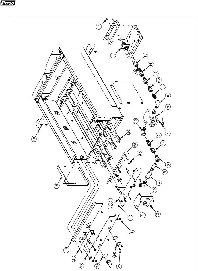
B) TANK JACKET EXTERNAL
|
|
Tank Jacket External Drawing B Parts List |
|
|
|
|
|
ITEM# |
PART# |
PART DESCRIPTION |
|
1 |
PP10693 |
SCREW 10 - 24 X 3/8 |
|
2 |
B2005401 |
SOLID STATE THERMOSTAT FBG |
|
3 |
P0092300 |
NUT HEX KEP 10-24 |
|
4 |
P7037678 |
ELBOW 90 DEGREE 1/2 NPT BLACK IRON |
|
5 |
P7037095 |
NIPPLE 1/2 NPT X 3 BLACK IRON |
|
6 |
P7037771 |
ELBOW 45 DEGREE STREET 1/2 NPT BLACK IRON |
|
7 |
60127601 |
ADAPTER FEMALE 15/16 SWIVEL FLARE X MALE 1/2 NPT |
|
8 |
60125901 |
GAS VALVE VENT TUBE |
|
9 |
60113501 |
GAS VALVE FAST ACTING 24V VR8204 NATURAL |
|
60113502 |
GAS VALVE FAST ACTING 24V VR8204 PROPANE |
||
|
|||
10 |
P7037750 |
ELBOW 90 DEGREE STREET 1/2 NPT BLACK IRON |
|
11 |
P7037090 |
NIPPLE 1/2 NPT X CLOSE BLACK IRON |
|
12 |
60127501 |
ADAPTER FEMALE 1/2 NPT X MALE 15/16 FLARE |
|
13 |
60127601 |
ADAPTER FEMALE 15/16 SWIVEL FLARE X MALE 1/2 NPT |
|
14 |
60128101 |
GAS SUPPLY SHUTOFF VALVE |
|
60128015 |
FLEXIBLE GAS ONLY 22" TUBING WITH FITTINGS POST 5/05 |
||
|
|||
15 |
60128014 |
FLEXIBLE GAS ONLY 22" TUBING WITH FITTINGS PRIOR TO 5/05 |
|
16 |
A8029105 |
GAS SUPPLY FITTING SHORT POST 5/05 |
|
A8029103 |
GAS SUPPLY FITTING LONG PRIOR TO 5/05 |
||
|
|||
17 |
60129301 |
SCREW 10-24 X 5/8 W/LOC-TITE |
|
18 |
A3347201-C |
TANK JACKET REAR SUPPORT |
|
19 |
A3347101-C |
TANK JACKET FRONT SUPPORT |
|
20 |
A3344901-C |
TANK JACKET FRONT EXHAUST FBG18 |
|
A3344903-C |
TANK JACKET FRONT EXHAUST FBG24 |
||
|
|||
21 |
A3345601-C |
TANK JACKET UPPER COVER |
|
22 |
A3345001-C |
TANK JACKET LOWER COVER FBG18 |
|
A3345003-C |
TANK JACKET LOWER COVER FBG18 |
||
|
|||
23 |
A8003001 |
SIGHT GLASS 1.25 OD |
|
24 |
A8003301-C |
SIGHT GLASS RETAINING WASHER |
|
25 |
PP10391 |
SCREW #6 X 3/8 TYPE B |
|
26 |
P0075400 |
SCREW 10 - 24 X 1/2 SELF TAP |
|
|
P6071343 |
#43 ORIFICE NATURAL FBG18 |
|
27 |
A7513701 |
1.45 MM ORIFICE PROPANE FBG18 |
|
P6071340 |
#40 ORIFICE NATURAL FBG24 |
||
|
|||
|
P6071309 |
.0625 ORIFICE PROPANE FBG24 |
|
28 |
A8036501-C |
BURNER BRACKET RETAINER |
|
29 |
60138901 |
BURNER 1.25 DIAMETER |
|
30 |
B8039701 |
GAS MANIFOLD WELDMENT FBG |
|
31 |
60129701 |
BURNER FITTING |
8 |
L22-297 Rev 0 (06/06) |
Exploded Parts-FBG Gas Models for Long John Silver’s
Tank Jacket External Drawing B
L22-297 Rev 0 (06/06) |
9 |

Exploded Parts-FBG Gas Models for
Long John Silver’s
C) TANK JACKET INTERNAL
|
|
Tank Jacket Internal Drawing C Parts List |
|
|
|
|
|
ITEM# |
PART# |
PART DESCRIPTION |
|
1 |
A3347702-C |
TANK JACKET AIR PLATE FBG |
|
2 |
A3345701-C |
TANK JACKET BURNER MOUNT BRACKET FRONT FBG18 |
|
A3345703-C |
TANK JACKET BURNER MOUNT BRACKET FRONT FBG24 |
||
|
|||
3 |
A3345202-C |
TANK JACKET BURNER MOUNT PLATE FBG18 |
|
A3345204-C |
TANK JACKET BURNER MOUNT PLATE FBG24 |
||
|
|||
4 |
PP10877 |
INSULATION RETAINING WASHER (FOR PIN ON ITEMS 43 AND 44) |
|
5 |
A3346001 |
TANK JACKET INSULATION FBG |
|
6 |
A3345901-C |
TANK JACKET SIDE INSERT LEFT-HAND FBG |
|
7 |
A3345903-C |
TANK JACKET SIDE INSERT RIGHT-HAND FBG |
|
8 |
A3527401-C |
FLUE DRAFT RESTRICTOR FBG18 |
|
A3527403-C |
FLUE DRAFT RESTRICTOR FBG24 |
||
|
|||
9 |
B3504501 |
FLUE WELDMENT FBG18 |
|
B3504601 |
FLUE WELDMENT FBG24 |
||
|
|||
10 |
A3527301-C |
FLUE BOX FBG18 |
|
A3527303-C |
FLUE BOX FBG24 |
||
|
|||
11 |
A3345501-C |
TANK JACKET BURNER MOUNT BRACKET REAR FBG18 |
|
A3345503-C |
TANK JACKET BURNER MOUNT BRACKET REAR FBG24 |
||
|
|||
12 |
A3347601-C |
TANK JACKET BURNER MOUNT STIFFENER FBG18 |
|
A3347603-C |
TANK JACKET BURNER MOUNT STIFFENER FBG24 |
||
|
|||
13 |
A7031301-C |
FILTER RETURN BRACKET UPPER FBG |
|
14 |
60131801 |
FILTER RETURN VALVE 3 WAY |
|
15 |
A7031701-C |
FILTER RETURN BRACKET LOWER FBG |
|
16 |
60128010 |
FLEXIBLE TUBING WITH FITTINGS 22" .56 OD |
|
17 |
60129902 |
ADAPTER MALE 15/16 FLARE X MALE 1/2 NPT |
|
18 |
P7037678 |
ELBOW 90 DEGREE 1/2 NPT BLACK IRON |
|
19 |
P7037750 |
ELBOW 90 DEGREE STREET 1/2 NPT BLACK IRON |
|
20 |
60130101 |
ADAPTER MALE 1/2 NPT X FEMALE 7/8 SWIVEL |
|
21 |
A8036403 |
FLAME SENSOR FBG |
|
22 |
P0075200 |
SCREW 8 - 18 X 1/2 HEX SELF DRILL |
|
23 |
A8037001-C |
PILOT ELECTRODE ALIGNMENT BRACKET |
|
24 |
60128804 |
PILOT REVERSE STANDING 2.67 HOOD NAT FBG |
|
60128805 |
PILOT REVERSE STANDING 2.67 HOOD LP FBG |
||
|
|||
25 |
60119001 |
FLEXIBLE TUBING WITHOUT FITTINGS 18" 1/4 OD |
|
26 |
A8036701-C |
PILOT BRACKET FBG |
|
27 |
60088001 |
SCREW, 10 - 32 X 1/4 HEX STAINLESS |
|
28 |
A8037102-C |
PILOT MOUNTING BRACKET FBG |
|
29 |
A3345103-C |
TANK JACKET SPACER RIGHT-HAND FBG18 |
|
A3345107-C |
TANK JACKET SPACER RIGHT-HAND FBG24 |
||
|
|||
30 |
A3345101-C |
TANK JACKET SPACER LEFT-HAND FBG18 |
|
A3345105-C |
TANK JACKET SPACER LEFT-HAND FBG24 |
||
|
|||
31 |
PP10266 |
SCREW 4 - 40 X 1/4 |
|
32 |
B5305001 |
DRAIN VALVE INTERLOCK ASSEMBLY |
|
33 |
A7028501-C |
RETURN HANDLE BRACKET |
|
34 |
P0007300 |
SCREW 8 - 32 1/4 HEX |
|
35 |
PP10687 |
SCREW 10 - 24 X 5/16 |
|
36 |
A8036801-C |
HI-LIMIT BRACKET FBG |
|
37 |
PP10084 |
HI-LIMIT LCHMO5030 |
|
38 |
B6745502 |
HI-LIMIT WIRING 24VAC FBG |
|
39 |
A6050401 |
HI-LIMIT LABEL (REFERENCE LABEL SHEET A6064801) |
|
40 |
P0075400 |
SCREW 10-24 X 1/2 SELF TAP |
|
41 |
A8036601-C |
BURNER BRACKET FRONT FBG18 |
|
A8036603-C |
BURNER BRACKET REAR FBG24 |
||
|
|||
42 |
A3347802-C |
TANK JACKET AIR PLATE FRONT FBG |
|
43 |
B3326601 |
TANK JACKET SIDE WELDMENT LEFT-HAND FBG |
|
44 |
B3326602 |
TANK JACKET SIDE WELDMENT RIGHT-HAND FBG |
|
45 |
A3345301-C |
TANK JACKET BOTTOM FBG18 |
|
A3345303-C |
TANK JACKET BOTTOM FBG24 |
||
|
10 |
L22-297 Rev 0 (06/06) |
 Loading...