

Page 1
DVD RECEIVER
XV-HTD1
THIS MANUAL IS APPLICABLE TO THE FOLLOWING MODEL(S) AND TYPE(S).
Type
DBDXJ/RC AC110-127V/220-230V/240V 3 With the voltage selector
DDXJ/AR AC110-127V/220-230V/240V 4 With the voltage selector
DDXJ/RA AC110-127V/220-230V/240V 1 With the voltage selector
DDXJ/RB AC110-127V/220-230V/240V 2 With the voltage selector
DLXJ/NC AC110-127V/220-230V/240V 3 With the voltage selector
YPWXJ AC240V 4 –––––––
Model
XV-HTD1 the following method.
Power Requirement Region No.
The voltage can be converted by
ORDER NO.
RRV2478
This product is component of system.
Component System Service Manual Remarks
DVD SURROUND SYSTEM
DVD RECEIVER
SPEAKER SYSTEM S-HTD1 RRV2456
XV-HTD1 RRV2478 (RRV2452) This service manual
¶ This service manual should be used together with the following manual(s):
Model No. Order No. Remarks
XV-HTD510/KUXJ
RRV2452
CONTENTS
1. SAFETY INFORMATION
2. CONTRAST OF MISCELLANEOUS PARTS
3. SCHEMATIC DIAGRAM
PIONEER CORPORATION 4-1, Meguro 1-chome, Meguro-ku, Tokyo 153-8654, Japan
PIONEER ELECTRONICS SERVICE, INC. P.O. Box 1760, Long Beach, CA 90801-1760, U.S.A.
PIONEER EUROPE NV Haven 1087, Keetberglaan 1, 9120 Melsele, Belgium
PIONEER ELECTRONICS ASIACENTRE PTE. LTD. 253 Alexandra Road, #04-01, Singapore 159936
PIONEER CORPORATION 2001
......................................
........
.......................................
2
3
7
T – ZZK JUNE 2001 Printed in Japan
Page 2
XV-HTD1
1. SAFETY INFORMATION
THE AEL(ACCESSIBLE EMISSION LEVEL) OF THE LASER POWER OUTPUT IS LESS THAN CLASS 1
BUT THE LASER COMPONENT IS CAPABLE OF EMITTING RADIATION EXCEEDING THE LIMIT FOR
CLASS1.
A SPECIALLY INSTRUCTED PERSON SHOULD DO SERVICING OPERATION OF THE APPARATUS.
LASER DIODE CHARACTERISTICS
FOR DVD : MAXIMUM OUTPUT POWER : 5 mW
WAVELENGTH : 655 nm
FOR CD : MAXIMUM OUTPUT POWER : 5mW
WAVELENGTH : 785 nm
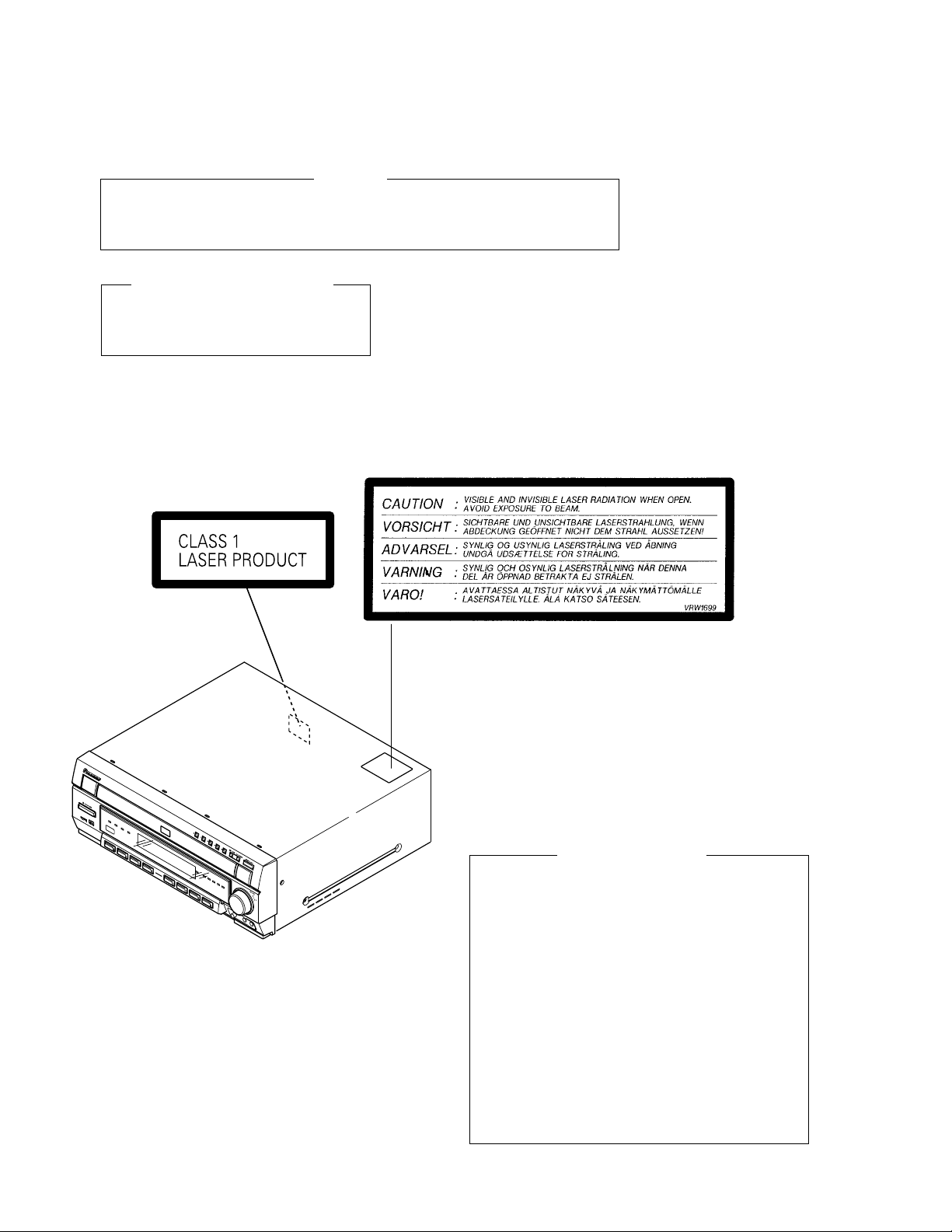
LABEL CHECK
Printed on the Rear Panel
WARNING
Additional Laser Caution
1. Inside detection switch (S201 on the SMEB assy) and clampstatus detection switch (S11 on the TRSB assy) are detected b y
the microprocessor (IC11 in the DVDM assy).
• To permit the laser diode to oscillate, it is required to set the
inside detection switch for the inside position (S201 : ON) and to
set the loading-status detection switch for the clamp position (the
center terminal of S11 is shorted to +3.3V). The 655 nm laser
diode for DVD oscillation will continue if pin 19 of IC1 is shorted
to +5V (fault condition) in the DVDM assy.
The 785 nm laser diode for CD oscillates if pin 20 of IC1 is shorted
to +5V in the DVDM assy.
In the test mode ∗ , the laser diode oscillates when microprocessor detects a PLAY signal, or when the PLAY key is pressed
(S5817 ON in the KEYB assy), with the above requirements satisfied.
2. When the cover is open, close vie wing through the objective lens
with the naked eye will cause exposure to the laser beam.
∗ : Refer to page 74 on service manual RRV2452.
2
Page 3
XV-HTD1
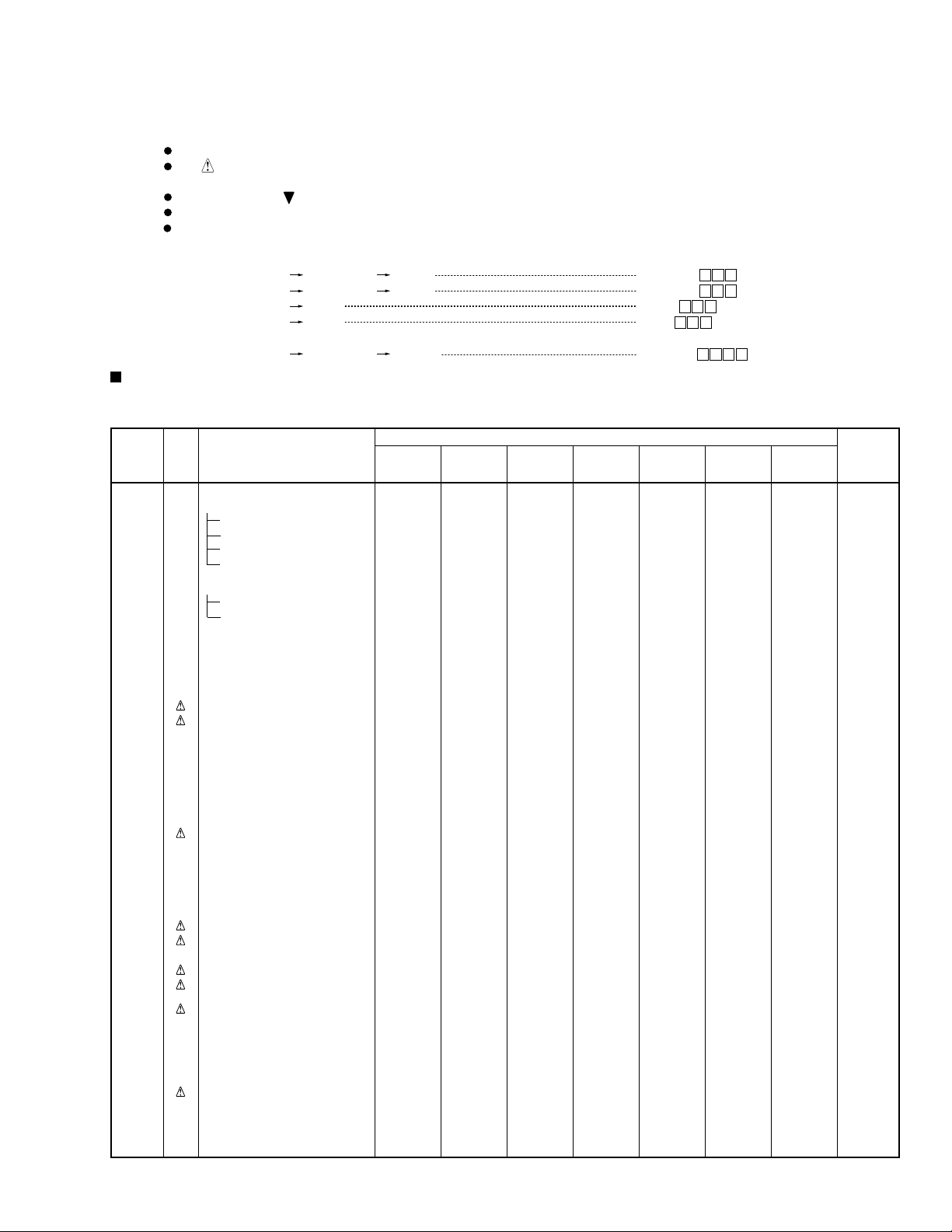
2. CONTRAST OF MISCELLANEOUS PARTS
NOTES:
CONTRAST T ABLE
XV-HTD1/DBDXJ/RC, DDXJ/AR, DDXJ/RA, DDXJ/RB, DLXJ/NC, YPWXJ and XV-HTD510/KUXJ are constructed
the same except for the following :
Ref. No. Mark Symbol and Description XV-HTD510 XV-HTD1 XV-HTD1 XV-HTD1 XV-HTD1 XV-HTD1 XV-HTD1 Remarks
P5- 2 PRIMARY ASSY XWZ3432 XWZ3434 XWZ3434 XWZ3434 XWZ3434 XWZ3434 XWZ3436
P5- 3 FRONT AMP ASSY XWZ3438 XWZ3440 XWZ3440 XWZ3440 XWZ3440 XWZ3440 XWZ3441
P5- 4 REAR AMP ASSY XWZ3442 XWZ3444 XWZ3444 XWZ3444 XWZ3444 XWZ3444 XWZ3445
P5- 6 MIC HP ASSY XWZ3450 XWZ3452 XWZ3452 XWZ3452 XWZ3452 XWZ3452 XWZ3452
P5- 7 INPUT ASSY XWZ3455 XWZ3457 XWZ3457 XWZ3457 XWZ3457 XWZ3457 XWZ3458
P5- 8 VIDEO ASSY XWZ3459 XWZ3486 XWZ3486 XWZ3486 XWZ3486 XWZ3486 XWZ3460
P5- 9 MAIN ASSY XWX3030 XWX3032 XWX3032 XWX3032 XWX3032 XWX3032 XWX3033
P5-10 DSP ASSY XWX3040 XWX3041 XWX3041 XWX3041 XWX3041 XWX3041 XWX3041
P3- 1 Power Cord ADG7022 ADG1158 ADG1154 ADG1158 ADG1158 ADG1154 ADG1160
P3- 1 Power Cord Not used Not used XDG3009 Not used Not used Not used Not used
P3- 9 Packing Case XHD3171 XHD3194 XHD3194 XHD3194 XHD3194 XHD3195 XHD3194
P3-12 NSP Warranty Card ARY7045 Not used Not used Not used Not used Not used ARY7047
P3-13 Operating Instructions(English) XRB3009 XRB3006 XRB3006 XRB3006 XRB3006 XRB3006 XRB3006
P5-12 Power Transformer (AC120V) XTS3051 Not used Not used Not used Not used Not used Not used
P5-12 Pow er Transformer Not used XTS3052 XTS3052 XTS3052 XTS3052 XTS3052 XTS3052
P5-13 Fuse (FU1 : 5A) REK1067 Not used Not used Not used Not used Not used Not used
P5-13 Fuse (FU1 : T4.0A) Not used REK1028 REK1028 REK1028 REK1028 REK1028 Not used
P5-13 Fuse (FU1 : T3.15A) Not used Not used Not used Not used Not used Not used REK1027
P5-18 5P F.F.C/60V XDD3093 Not used Not used Not used Not used Not used Not used
P5-18 8P F.F.C/60V Not used XDD3092 XDD3092 XDD3092 XDD3092 XDD3092 XDD3092
P5-22 Rear Panel XNC3094 XNC3100 XNC3101 XNC3103 XNC3103 XNC3104 XNC3102
P5-37 65 Label ARW7050 Not used Not used Not used Not used Not used Not used
Parts marked by "NSP" are generally unavailable because they are not in our Master Spare Parts List.
The mark found on some component parts indicates the importance of the safety factor of the part.
Therefore, when replacing, be sure to use parts of identical designation.
Screws adjacent to mark on product are used for disassembly.
Reference Nos. indicate the pages and Nos. in the service manual for the base model.
When ordering resistors, first convert resistance values into code form as shown in the following examples.
Ex.1 When there are 2 effective digits (any digit apart from 0), such as 560 ohm and 47k ohm (tolerance is shown by J=5%,
and K=10%).
560
47k
0.5
1
56 x 10
47 x 103
R50
1R0
1
561
473
RD1/4PU J
RD1/4PU J
RN2H K
RS1P K
561
473
R50
1R0
Ex.2 When there are 3 effective digits (such as in high precision metal film resistors).
5.62k RN1/4PC F562 x 10
PCB ASSEMBLIES
NSP COMPLEX ASSY XWM3187 XWM3189 XWM3189 XWM3189 XWM3189 XWM3189 XWM3191
NSP CONNECT ASSY XWM3193 XWM3195 XWM3195 XWM3195 XWM3195 XWM3195 XWM3196
PACKING SECTION
Operating Instructions(Chinese) Not used XRC3037 Not used Not used Not used XRC3037 Not used
Operating Instructions(Spanish) Not used Not used XRC3036 Not used Not used Not used Not used
Operating Instructions(Arabic) Not used Not used Not used Not used XRC3038 Not used Not used
AC Plug Adapter Not used Not used XKM3001 Not used Not used Not used Not used
Region Label Not used VRW1702 Not used VRW1708 VRW1701 Not used Not used
Caution Sheet AR Not used Not used XRH3002 Not used Not used Not used Not used
NSP UPC Label Not used Not used Not used XAX3272 Not used Not used Not used
EXTERIOR SECTION
(AC110-127V/220-230V/240V)
Fuse (FU2, FU3 : T2.0A) Not used REK1025 REK1025 REK1025 REK1025 REK1025 Not used No. 1
Mic Knob Not used XAB3014 XAB3014 XAB3014 XAB3014 XAB3014 XAB3014 No. 2
Caution Label Not used VRW1699 VRW1699 VRW1699 VRW1699 VRW1699 VRW1699 No. 3
NSP Fuse Card Not used AAX7099 AAX7099 AAX7099 AAX7099 AAX7099 AAX7493 No. 4
NSP Region Label Not used Not used Not used XAX3183 Not used Not used Not used No. 5
1
5621
Part No.
/KUXJ /DBDXJ/RC /DDXJ/AR /DDXJ/RA /DDXJ/RB /DLXJ/NC /YPWXJ
5621
3
Page 4
XV-HTD1
Part No.
Ref. No. Mark Symbol and Description XV-HTD510 XV-HTD1 XV-HTD1 XV-HTD1 XV-HTD1 XV-HTD1 XV-HTD1 Remarks
/KUXJ /DBDXJ/RC /DDXJ/AR /DDXJ/RA /DDXJ/RB /DLXJ/NC /YPWXJ
P6- 5 NSP Front Panel Assy XXG3070 XXG3073 XXG3073 XXG3073 XXG3073 XXG3073 XXG3073
P6- 6 Front Cap XAK3212 XAK3211 XAK3211 XAK3211 XAK3211 XAK3211 XAK3211
P6- 7 Display Panel XAK3213 XAK3215 XAK3215 XAK3215 XAK3215 XAK3215 XAK3215
P6- 8 Front Panel XMB3047 XMB3052 XMB3052 XMB3052 XMB3052 XMB3052 XMB3052
Notes : For PCB ASSEMBLIES, Refer to “CONTRAST OF PCB ASSEMBLIES” and “3. SCHEMATIC DIAGRAM”.
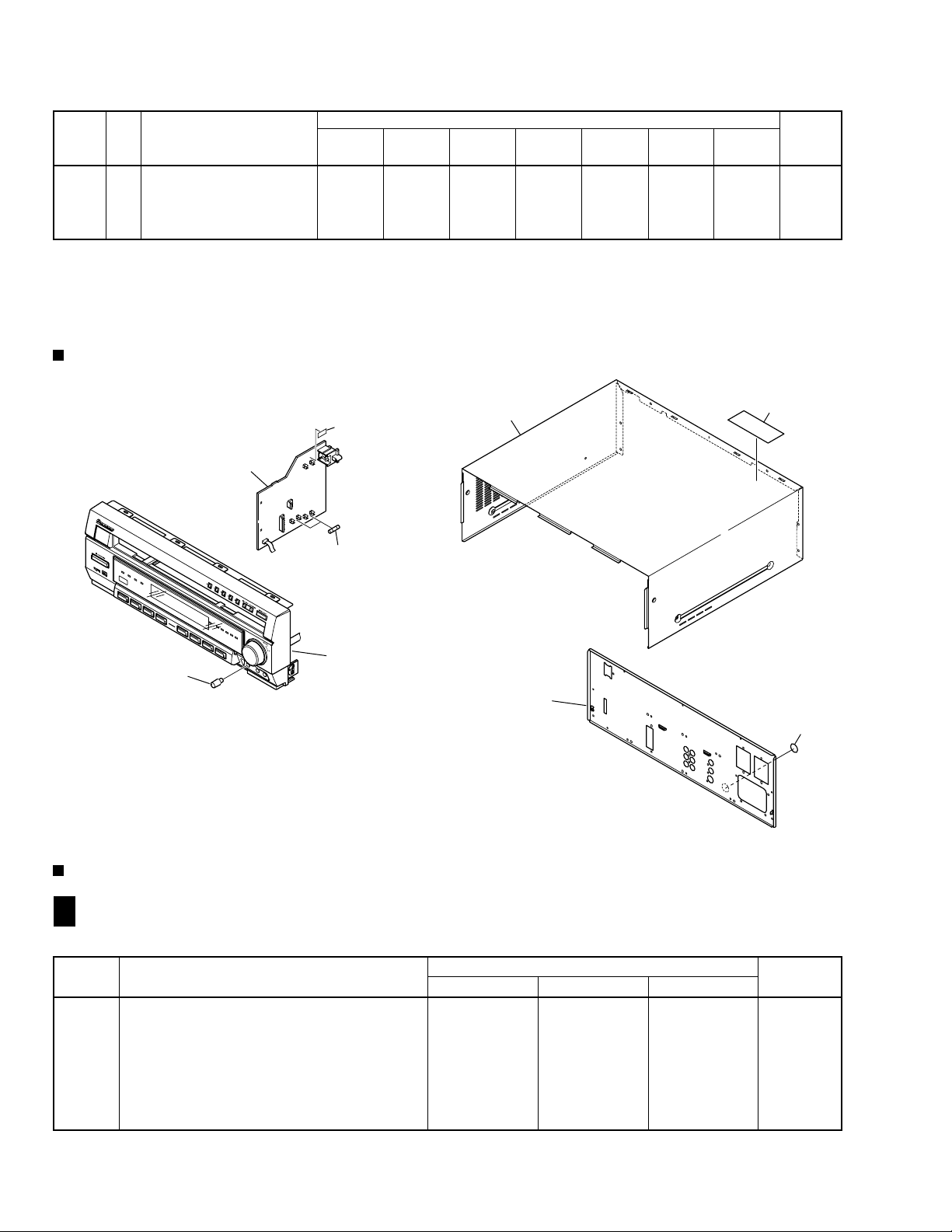
EXPLODED VIEWS
FRONT PANEL SECTION
The numbers in the remarks column correspond to the numbers on the “ EXPLODED VIEWS ”.
PRIMARY Assy
2
4
1
Front Panel
Bonnet Case
Rear Panel
3
5
CONTRAST OF PCB ASSEMBLIES
FRONT AMP ASSY
G
F
XWZ3440, XWZ3441 and XWZ3438 are constructed the same except for the following :
Mark Symbol and Description
D3371, D3372 1SS133 1SS133 Not used
D3381, D3382 Not used Not used 1SS355
L3361, L3362, L3661 ATH1004 ATH1004 ATH1009
C3329, C3365–C3368, C3371–C3373 Not used Not used CKSRYB104K25
C3369, C3370, C3669 Not used Not used CKSRYB103K50
C3773 Not used CEAT101M35 CEAT101M35
R3330, R3365–R3368 Not used Not used RS1/16S100J
R3361, R3362, R3661 RD1/2PMF100J RD1/2PMF100J RD1/2PMF101J
4
XWZ3438 XWZ3440 XWZ3441
Part No.
Remarks
Page 5
REAR AMP ASSY
H
F
XWZ3444, XWZ3445 and XWZ3442 are constructed the same except for the following :
Mark Symbol and Description
L3461, L3462, L3561 ATH-133 ATH-133 ATH-059
C3465–C3468, C3471, C3472, C3565, C3567, C3571 Not used Not used CKSRYB104K25
C3469, C3470, C3569 Not used Not used CKSRYB103K50
R3465–R3468, R3565, R3567 Not used Not used RS1/16S100J
R3461, R3462, R3561 RD1/2PMF100J RD1/2PMF100J RD1/2PMF101J
MAIN ASSY
I
F
XWZ3442 XWZ3444 XWZ3445
Part No.
XWX3032, XWX3033 and XWX3030 are constructed the same except for the following :
Mark Symbol and Description
IC3002, IC3181 Not used BA4558F-HT BA4558F-HT
IC3151, IC3152, IC3161, IC3171 NJM4558MD BA4558F-HT BA4558F-HT
C3011, C3014 Not used CEAT100M50 CEAT100M50
C3185 Not used CEJQ100M35 CEJQ100M35
C3186, C3187 Not used CKSRYB473K25 CKSRYB473K25
XWX3030 XWX3032 XWX3033
Part No.
XV-HTD1
Remarks
Remarks
C5830 Not used CEAT101M10 CEAT101M10
C5831 Not used CEAT101M25 CEAT101M25
R3181 Not used RSD1/4PU332J RSD1/4PU332J
R3182 Not used RS1/16S332J RS1/16S332J
R3183, R3184, R3254, R3258, R3263, R3264 Not used RS1/16S103J RS1/16S103J
R3186 RS1/16S0R0J Not used Not used
R3189, R3190 Not used RS1/16S682J RS1/16S682J
R3255, R3257, R3259, R3261 Not used RS1/16S473J RS1/16S473J
R3256, R3260 Not used RS1/16S182J RS1/16S182J
R5558 Not used RS1/16S153J RS1/16S103J
R5559 RS1/16S223J RS1/16S332J RS1/16S822J
R5830 Not used RS1/16S224J RS1/16S224J
R5831 Not used RS1/16S101J RS1/16S101J
CN5501 5P FFC CONNECTOR 52045-0545 Not used Not used
CN5502 8P FFC CONNECTOR Not used 52045-0845 52045-0845
INPUT ASSY
K
F
XWZ3457, XWZ3458 and XWZ3445 are constructed the same except for the following :
Mark Symbol and Description
IC5353 Not used BA4558F-HT BA4558F-HT
C5203, C5204, C5209, C5210 CCSRCH101J50 CCSRCH101J50 CKSRYB102K50
C5241, C5247 Not used CEAT100M50 CEAT100M50
R5241–R5248 Not used RS1/16S332J RS1/16S332J
R9001, R9002 RS1/16S0R0J Not used Not used
XWZ3445 XWZ3457 XWZ3458
Part No.
Remarks
JA5201 PIN JACK 6P AKB7113 AKB7012 AKB7113
5
Page 6
XV-HTD1
VIDEO ASSY
L
F
XWZ3486, XWZ3460 and XWZ3459 are constructed the same except for the following :
Mark Symbol and Description
L5103 Not used Not used VTL1112
L5371, L5378, L5379 VTL1087 VTL1087 VTL1081
C5382 Not used Not used CCSRCH331J50
R5101 RS1/16S750J RS1/16S750J Not used
R5109 RS1/16S0R0J RS1/16S0R0J Not used
R5110 Not used Not used RS1/16S750J
JA5103 PIN JACK 1P AKB7111 VKB1077 AKB7111
DSP ASSY
M
F
XWZ3459 XWZ3486 XWZ3460
Although XWX3040 and XWX3041 are different in part number, they consist of the same components.
MIC HP ASSY
O
F
Part No.
Remarks
XWZ3452 and XWZ3450 are constructed the same except for the following :
Mark Symbol and Description
IC5802 Not used BA4558F
C5805 Not used CKSRYB681K50
C5806 Not used CEAL1R0M50
C5807, C5812, C5813 Not used CEAL100M16
C5809 Not used CKSRYB471K50
C5810 Not used CKSRYB104K25
C5811 Not used CKSRYB473K25
R5866 Not used RS1/16S222J
R5867, R5872, R5874 Not used RS1/16S104J
R5868, R5885 Not used RS1/16S223J
R5869 Not used RS1/16S224J
R5870 Not used RS1/16S681J
R5871 Not used RS1/16S102J
R5873 Not used RS1/16S0R0J
VR5801 Not used XCS3005
CN5807 5P FFC CONNECTOR 52044-0545 Not used
CN5807 8P FFC CONNECTOR Not used 52044-0845
JA5801 MINI JACK Not used XKN3008
PRIMARY ASSY
T
F
XWZ3450 XWZ3452
Part No.
XWZ3434, XWZ3436 and XWZ3432 are constructed the same except for the following :
Mark Symbol and Description
T2 STANDBY TRANS ATT7049 XTT3004 ATT7050
R1 (2.2MΩ/ 1/2W) RCN1080 Not used Not used
AN1 AC INLET 1P XKP3042 XKP3041 XKP3041
CN2 4P-VH CONNECTOR Not used B4P7-VH B4P7-VH
H3–H6 FUSE CLIP Not used AKR7001 Not used
XWZ3432 XWZ3434 XWZ3436
Part No.
Remarks
Remarks
KN2 EARTH METAL FITTING VNF1084 Not used Not used
S1 VOLTAGE SELECT SWITCH Not used XKX3001 Not used
6
Page 7

1
234
3. SCHEMATIC DIAGRAM
XV-HTD1
Note : When ordering service parts, be sure to refer to "EXPLODED VIEWS and PARTS LIST" or "PCB PARTS LIST"
3.1 MIC HP ASSY
MIC HP ASSY (XWZ3452)
O F
A
B
I 3/3F
CN5502
O
1
2
3
F
4
C
D
7
Page 8

1
XV-HTD1
3.2 FRONT AMP ASSY
23
4
A
CN3051
FRONT AMP ASSY
G
F
(EXCEPT YPWXJ : XWZ3440)
(YPWXJ ONLY : XWZ3441)
I 2/3F
B
YPWXJ ONLY
CN3053
I 2/3F
C
D
: The power supply is shown with the marked box.
8
G
F
1234
Page 9

5
678
XV-HTD1
EXCEPT YPWXJ
YPWXJ ONLY
Not used
A
Not used
YPWXJ ONLY
SPEAKERS
B
C
DC FAN MOTOR
D
(FL)
: FL AUDIO SIGNAL ROUTE
(SW)
: SW AUDIO SIGNAL ROUTE
F
9
G
5
6
7
8
Page 10

1
XV-HTD1
3.3 REAR AMP ASSY
23
4
A
CN3052
REAR AMP ASSY
H
F
(EXCEPT YPWXJ : XWZ3444)
(YPWXJ ONLY : XWZ3445)
I 2/3F
B
CN3054
I 2/3F
C
D
: The power supply is shown with the marked box.
10
H
F
1234
Page 11

5
678
XV-HTD1
A
(SL)
: SL AUDIO SIGNAL ROUTE
(C)
: C AUDIO SIGNAL ROUTE
YPWXJ ONLY
EXCEPT YPWXJ
YPWXJ ONLY
SPEAKERS
B
C
D
F
11
H
5
6
7
8
Page 12

1
XV-HTD1
3.4 MAIN ASSY (2/3)
A
CN3702
M1/2
B
23
I
3/3F
I 2/3 F
MAIN ASSY
(EXCEPT YPWXJ : XWX3032)
(YPWXJ ONLY : XWX3033)
4
I
1/3
C
I
I
3/3F
1/3
(VCB)
K F
CN5208
D
CN5351
L F
12
I
2/3 F
1234
Page 13

5
678
XV-HTD1
A
CN3301CN3501CN3302CN3502
B
H FH F G FG F
C
(VCB)
: VCB SIGNAL ROUTE
(Y)
: Y SIGNAL ROUTE
(C)
: C SIGNAL ROUTE
D
CN201
J
(DVD)
: DVD AUDIO SIGNAL ROUTE
(DI)
: DI AUDIO SIGNAL ROUTE
(FL)
: FL AUDIO SIGNAL ROUTE
5
6
(HP)
: HP AUDIO SIGNAL ROUTE
(SL)
: SL AUDIO SIGNAL ROUTE
(C)
: C AUDIO SIGNAL ROUTE
7
(SW)
: SW AUDIO SIGNAL ROUTE
(TX)
: TX AUDIO SIGNAL ROUTE
I
2/3 F
8
13
Page 14

1
XV-HTD1
3.5 MAIN ASSY (3/3)
23
4
I 3/3 F
A
CN15
MAIN ASSY
(EXCEPT YPWXJ : XWX3032)
(YPWXJ ONLY : XWX3033)
I
1/3
I
2/3F
I
1/3
I
2/3F
I
1/3
F 3/3
B
(VCB)
I
2/3F
I
1/3
C
CN5
EXCEPT
YPWXJ
YPWXJ
ONLY
F 2/3
I
D
1/3
14
T F
N
N
I
3/3 F
1234
CN5801
CN5802
J13
Page 15

5
678
XV-HTD1
3.1V
3.1V
0V
2.5V
2.5V
2.5V
LEVEL SHIFT
1.6V
1.6V
0V
0V
O F
CN5807
F 1/3
CN55
A
CN11
A
B
C
CN3701
M1/2
FOR DOWNLOAD
(VCB)
: VCB SIGNAL ROUTE
(Y)
: Y SIGNAL ROUTE
(C)
: C SIGNAL ROUTE
5
6
(DVD)
: DVD AUDIO SIGNAL ROUTE
(HP)
: HP AUDIO SIGNAL ROUTE
(T)
: TRAY POSITION SERVO LOOP LINE
(S)
: SEDO SERVO LOOP LINE
7
I
3/3 F
8
15
D
Page 16

1
23
XV-HTD1
3.6 INPUT and VIDEO ASSYS
4
A
YPWXJ ONLYEXCEPT YPWXJ
B
INPUT ASSY
K
F
(EXCEPT YPWXJ : XWZ3457)
(YPWXJ ONLY : XWZ3458)
C
VIDEO ASSY
L
F
(EXCEPT YPWXJ : XWZ3486)
(YPWXJ ONLY : XWZ3460)
D
16
K
L
F
1234
F
YPWXJ ONLYEXCEPT YPWXJ
Page 17

5
678
XV-HTD1
A
M1/2
CN3703
I 2/3F
CN5209
B
: The power supply is shown with the marked box.
(VCB)
(VCB)
(VCB)
(VCB)
(VCB)
I 2/3F
CN5352
C
YPWXJ ONLYEXCEPT YPWXJ
(VCB)
(VCB)
: VCB SIGNAL ROUTE
(Y)
: Y SIGNAL ROUTE
(C)
: C SIGNAL ROUTE
D
(DVD)
: DVD AUDIO SIGNAL ROUTE
(DI)
: DI AUDIO SIGNAL ROUTE
(FL)
: FL AUDIO SIGNAL ROUTE
5
6
(AI)
: AUX IN AUDIO SIGNAL ROUTE
(AO)
: AUX OUT AUDIO SIGNAL ROUTE
(TV)
: TV AUDIO SIGNAL ROUTE
7
(TX)
: TX AUDIO SIGNAL ROUTE
K
F
L
8
F
17
Page 18

1
XV-HTD1
3.7 PRIMARY ASSY
A
I 1/3
B
CN5011
23
XTS3052
4
I 1/3
CN5012
C
I 3/3F
CN8503
D
EXCEPT YPWXJ : XTT3004
YPWXJ ONLY : ATT7050
18
T
F
1234
Page 19

5
• NOTE FOR FUSE REPLACEMENT
CAUTION -
FOR CONTINUED PROTECTION AGAINST RISK OF FIRE,
REPLACE WITH SAME TYPE AND RATINGS OF FUSE.
678
XV-HTD1
A
PRIMARY ASSY
T
F
FU2, FU3 : REK1025 (T2.0A)
(EXCEPT YPWXJ : XWZ3434)
(YPWXJ ONLY : XWZ3436)
B
FU1: REK1028 (T4.0A)
FU1: REK1027 (T3.15A)
EXCEPT YPWXJ
YPWXJ ONLY
C
D
F
19
T
5
6
7
8
 Loading...