

Pioneer XV-DV434, XV-DV333, XV-DV535 Service Manual
PIONEER CORPORATION 4-1, Meguro 1-chome, Meguro-ku, Tokyo 153-8654, Japan
PIONEER ELECTRONICS (USA) INC. P.O. Box 1760, Long Beach, CA 90801-1760, U.S.A.
PIONEER EUROPE NV Haven 1087, Keetberglaan 1, 9120 Melsele, Belgium
PIONEER ELECTRONICS ASIACENTRE PTE. LTD. 253 Alexandra Road, #04-01, Singapore 159936
PIONEER CORPORATION 2005
7
Q
Q
TEL 13942296513 QQ 376315150 892498299
3
DVD/CD RECEIVER
6
3
1
5
1
5
0
XV-DV333
XV-DV434
XV-DV535
8
XV-DV333
9
OPEN/CLOSEDVD/CD
2
FM/AM
4
9
PHONES
STANDBY/ON
VOLUME
8
2
9
ORDER NO.
RRV3171
9
TEL 13942296513 QQ 376315150 892498299
THIS MANUAL IS APPLICABLE TO THE FOLLOWING MODEL(S) AND TYPE(S).
TEL
13942296513
Model Type Power Requirement
XV-DV333 MLXJ AC220-230V 3
XV-DV333 YLXJ/NC AC240V 3
XV-DV333 YPWXJ AC240V 4
XV-DV434 MLXJ AC220-230V 3
XV-DV434 YLXJ/NC AC240V 3
XV-DV434 YPWXJ AC240V 4
XV-DV535 MLXJ AC220-230V 3
XV-DV535 YLXJ/NC AC240V 3
For details, refer to "Important Check Points for Good Servicing".
Q
Q
3
7
6
3
1
5
1
5
Regional restriction
codes (Region No.)
0
8
9
2
4
9
2
8
Remarks
9
9
w
w
w
.
xia
o
y
u
1
6
3
.
c
o
m
T-ZZK JULY 2005 printed in Japan
1234
SAFETY INFORMATION
A
This service manual is intended for qualified service technicians ; it is not meant for the casual do-
Q
Q
it-yourselfer. Qualified technicians have the necessary test equipment and tools, and have been
trained to properly and safely repair complex products such as those covered by this
manual.Improperly performed repairs can adversely affect the safety and reliability of the product
and may void the warranty. If you are not qualified to perform the repair of this product properly and
safely, you should not risk trying to do so and refer the repair to a qualified service technician.
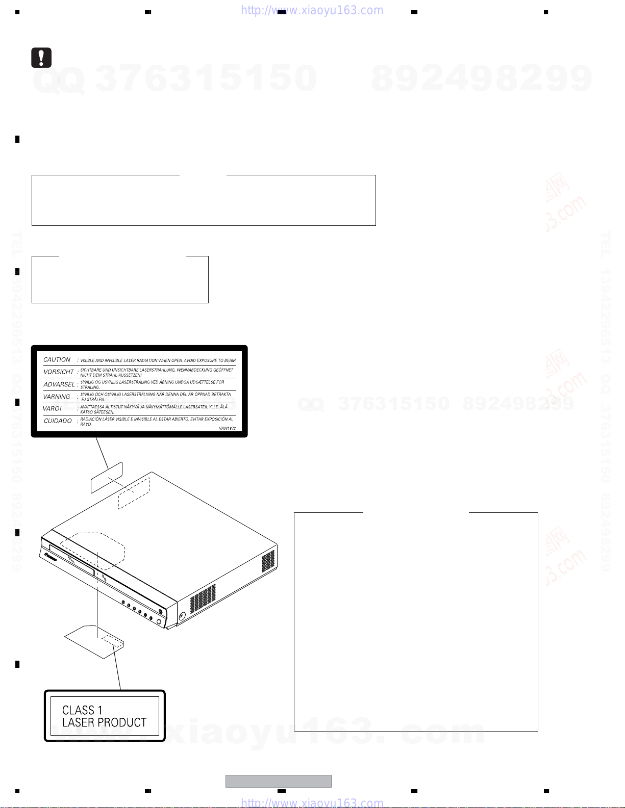
THE AEL (ACCESSIBLE EMISSION LEVEL) OF THE LASER POWER OUTPUT IS LESS THAN CLASS 1
BUT THE LASER COMPONENT IS CAPABLE OF EMITTING RADIATION EXCEEDING THE LIMIT FOR
B
CLASS 1.
A SPECIALLY INSTRUCTED PERSON SHOULD DO SERVICING OPERATION OF THE APPARATUS.
TEL 13942296513 QQ 376315150 892498299
LASER DIODE CHARACTERISTICS
FOR DVD : MAXIMUM OUTPUT POWER : 5 mW
FOR CD : MAXIMUM OUTPUT POWER : 7 mW
WAVELENGTH : 650 nm
WAVELENGTH : 780 nm
3
7
6
3
1
WARNING !
5
1
5
0
8
9
2
4
9
8
2
9
9
TEL 13942296513 QQ 376315150 892498299
LABEL CHECK
C
TEL
D
E
13942296513
Name Label
VRW1872
4
2
9
8
0
5
1
5
1
3
6
7
3
Q
Q
Additional Laser Caution
1. Laser Interlock Mechanism
• Loading switch (S101 on the LOAB Assy) is used for interlock
mechanism of the laser.
When this switch turned ON in SW2 (CLOSE) side (OPEN signal is
0V and CLOSE signal is 3.5V), a laser becomes the status which can
completely oscillation.
Furthermore, the laser completely oscillates in the disc judgment and
disc playback.
When player is power ON state and laser diode is not completely
oscillating, 780nm laser diode is always oscillating by half power.
• Laser diode is driving with Q307 (650nm LD) and Q308 (780nm LD)
on the DVDM Assy.
Therefore, when short-circuit between the emitter and collector of these
transistors or the base voltage is supplied for transistors turn on, the
laser oscillates. (failure mode)
• In the test mode ∗ , there is the mode that the laser oscillates except
for the disc judgment and playback. LD ON mode in the test mode
oscillates with the laser forcibly.
The interlock mechanism mentioned above becomes invalid in this
mode.
9
8
2
9
9
2. When the cover is open, close viewing through the objective lens with
the naked eye will cause exposure to the laser beam.
F
w
w
w
2
1234
.
xia
o
y
XV-DV333
∗ : Refer to page 67.
u
1
6
3
.
c
o
m
5678
[Important Check Points for Good Servicing]
In this manual, procedures that must be performed during repairs are marked with the below symbol.
Please be sure to confirm and follow these procedures.
1. Product safety
Q
Q
TEL 13942296513 QQ 376315150 892498299
TEL
7
3
13942296513
6
Please conform to product regulations (such as safety and radiation regulations), and maintain a safe servicing environment by
following the safety instructions described in this manual.
1 Use specified parts for repair.
Use genuine parts. Be sure to use important parts for safety.
2 Do not perform modifications without proper instructions.
Please follow the specified safety methods when modification(addition/change of parts) is required due to interferences such as
radio/TV interference and foreign noise.
3 Make sure the soldering of repaired locations is properly performed.
When you solder while repairing, please be sure that there are no cold solder and other debris.
Soldering should be finished with the proper quantity. (Refer to the example)
4 Make sure the screws are tightly fastened.
Please be sure that all screws are fastened, and that there are no loose screws.
5 Make sure each connectors are correctly inserted.
Please be sure that all connectors are inserted, and that there are no imperfect insertion.
6 Make sure the wiring cables are set to their original state.
Please replace the wiring and cables to the original state after repairs.
In addition, be sure that there are no pinched wires, etc.
7 Make sure screws and soldering scraps do not remain inside the product.
Please check that neither solder debris nor screws remain inside the product.
8 There should be no semi-broken wires, scratches, melting, etc. on the coating of the power cord.
Damaged power cords may lead to fire accidents, so please be sure that there are no damages.
If you find a damaged power cord, please exchange it with a suitable one.
9 There should be no spark traces or similar marks on the power plug.
When spark traces or similar marks are found on the power supply plug, please check the connection and advise on secure
connections and suitable usage. Please exchange the power cord if necessary.
0 Safe environment should be secured during servicing.
When you perform repairs, please pay attention to static electricity, furniture, household articles, etc. in order to prevent injuries.
Please pay attention to your surroundings and repair safely.
3
1
5
1
5
0
Q
Q
3
7
6
8
3
9
1
5
1
2
5
4
0
9
8
9
8
2
4
2
9
8
9
2
9
A
9
B
TEL 13942296513 QQ 376315150 892498299
C
9
D
w
w
2. Adjustments
To keep the original performance of the products, optimum adjustments and confirmation of characteristics within specification.
Adjustments should be performed in accordance with the procedures/instructions described in this manual.
3. Lubricants, Glues, and Replacement parts
Use grease and adhesives that are equal to the specified substance.
Make sure the proper amount is applied.
4. Cleaning
For parts that require cleaning, such as optical pickups, tape deck heads, lenses and mirrors used in projection monitors, proper
cleaning should be performed to restore their performances.
5. Shipping mode and Shipping screws
To protect products from damages or failures during transit, the shipping mode should be set or the shipping screws should be
installed before shipment. Please be sure to follow this method especially if it is specified in this manual.
w
.
xia
56
o
y
u
1
6
3
XV-DV333
.
c
7
o
E
F
m
3
8
1234
CONTENTS
SAFETY INFORMATION..................................................................................................................................... 2
1. SPECIFICATIONS ............................................................................................................................................ 5
2. EXPLODED VIEWS AND PARTS LIST ............................................................................................................ 6
A
B
TEL 13942296513 QQ 376315150 892498299
C
D
E
2.1 PACKING ................................................................................................................................................... 6
Q
Q
2.2 EXTERIOR SECTION................................................................................................................................ 8
2.3 FRONT PANEL SECTION ....................................................................................................................... 10
2.4 05 LOADER ASSY................................................................................................................................... 11
2.5 Traverse Mechanism Assy-S.................................................................................................................... 13
3. BLOCK DIAGRAM AND SCHEMATIC DIAGRAM..........................................................................................14
3.1 BLOCK DIAGRAM ................................................................................................................................... 14
3.2 OVERALL WIRING CONNECTION DIAGRAM........................................................................................ 16
3.3 DVDM ASSY (1/2).................................................................................................................................... 18
3.4 DVDM ASSY (2/2).................................................................................................................................... 20
3.5 DSP ASSY ............................................................................................................................................... 22
3.6 6CH AMP ASSY ...................................................................................................................................... 24
3.7 CONTROL (1/4) and TRADE 2 ASSYS................................................................................................... 26
3.8 CONTROL (2/4) ASSY............................................................................................................................. 28
3.9 CONTROL (3/4) ASSY............................................................................................................................. 30
3.10 CONTROL (4/4) ASSY........................................................................................................................... 32
3.11 POWER ASSY....................................................................................................................................... 34
3.12 TRADE 1 and VIDEO ASSYS ................................................................................................................ 36
3.13 DISPLAY and LED ASSYS .................................................................................................................... 38
3.14 WAVEFORMS ........................................................................................................................................ 40
4. PCB CONNECTION DIAGRAM ..................................................................................................................... 41
4.1 LOAB ASSY............................................................................................................................................. 41
4.2 DVDM ASSY............................................................................................................................................ 42
4.3 DSP, TRADE 2 and TRADE 1 ASSYS ..................................................................................................... 44
4.4 6CH AMP ASSY ...................................................................................................................................... 46
4.5 CONTROL ASSY..................................................................................................................................... 48
4.6 DISPLAY, VIDEO and LED ASSYS.......................................................................................................... 52
4.7 POWER ASSY......................................................................................................................................... 54
5. PCB PARTS LIST ........................................................................................................................................... 56
6. ADJUSTMENT ............................................................................................................................................... 62
TEL
6.1 ADJUSTMENT ITEMS AND LOCATION ................................................................................................. 62
6.2 JIGS AND MEASURING INSTRUMENTS............................................................................................... 62
6.3 NECESSARY ADJUSTMENT POINTS ................................................................................................... 63
6.4 TEST MODE ............................................................................................................................................ 64
6.5 MECHANISM ADJUSTMENT.................................................................................................................. 65
7. GENERAL INFORMATION ............................................................................................................................. 67
7.1 DIAGNOSIS ............................................................................................................................................. 67
7.1.1 TEST MODE ...................................................................................................................................... 67
7.1.2 DISPLAY SPECIFICATION OF THE TEST MODE ............................................................................ 68
7.1.3 FUNCTIONAL SPECIFICATION OF THE SHORTCUT KEY ............................................................ 69
7.1.4 SPECIFICATION OF MODEL INFORMATION DISPLAY .................................................................. 70
7.1.5 FUNCTIONAL SPECIFICATION OF THE SERVICE MODE ............................................................. 71
7.1.6 SERVICE TEST MODE ..................................................................................................................... 72
7.1.7 METHOD FOR DIAGNOSING DEGRADATION OF THE LDs ON THE PICKUP ASSY ................... 74
7.1.8 DVD TROUBLE SHOOTING.............................................................................................................. 75
7.1.9 ID NUMBER AND ID DATA SETTING............................................................................................... 78
7.1.10 DSP TROUBLE SHOOTING ........................................................................................................... 81
7.1.11 DISASSEMBLY ................................................................................................................................ 83
7.2 PARTS...................................................................................................................................................... 92
7.2.1 IC ....................................................................................................................................................... 92
7.3 EXPLANATION ........................................................................................................................................ 96
7.3.1 SEQUENCE AFTER POWER ON..................................................................................................... 96
7.3.2 PROTECTION CIRCUIT.................................................................................................................... 97
8. PANEL FACILITIES ...................................................................................................................................... 102
3
7
6
3
1
13942296513
5
1
5
0
Q
Q
3
7
6
8
3
9
1
5
1
2
5
4
0
9
8
9
8
2
4
2
9
8
9
2
9
9
TEL 13942296513 QQ 376315150 892498299
9
F
w
w
w
4
1234
.
xia
o
y
u
1
6
XV-DV333
3
.
c
o
m
5678
1. SPECIFICATIONS
• Amplifier section
Front, Center. . . . . . . . . . . . . . . 100 W per channel
Subwoofer . . . . 100 W (100 Hz, 10 % T.H.D., 6 Ω)
7
Q
Q
TEL 13942296513 QQ 376315150 892498299
TEL
3
13942296513
Accessories
• Power cord
(MLXJ, YLXJ/NC : ADG1154)
(YPWXJ : ADG7099)
6
• Disc section
Digital audio
characteristics . . . . . . . . . . DVD fs: 96 kHz, 24-bit
Type . . . . . . . . DVD system, Video CD/Super VCD
Frequency
response . . . . . . 4Hz to 44 kHz (96kHz sampling) /
Wow and Flutter Limit of measurement
• FM tuner section
Frequency range. . . . . . . . . 87.5 MHz to 108 MHz
Antenna . . . . . . . . . . . . . . . . . . . 75 Ω, unbalanced
• AM tuner section
Frequency range
With 9kHz step . . . . . . . . . 531 kHz to 1,602 kHz
With 10kHz step . . . . . . . . 530 kHz to 1,700 kHz
Antenna . . . . . . . . . . . . . . . . . . . . . . Loop antenna
• Miscellaneous
Power requirements:
Singapore / Indonesia / Hong Kong /
Phillipines model . . . . . AC 220-230 V, 50/60 Hz
Malaysia model. . . . . . . . . . AC 240 V, 50/60 Hz
Taiwan model. . . . . . . . . . AC 110-120 V, 60 Hz
Power consumption . . . . . . . . . . . . . . . . . . . 175 W
Power consumption in standby (MLXJ). . . . . 0.5 W
Dimensions. . . . . 420 (W) x 70 (H) x 399.5 (D) mm
Weight . . . . . . . . . . . . . . . . . . . . . . . . . . . . . 7.0 kg
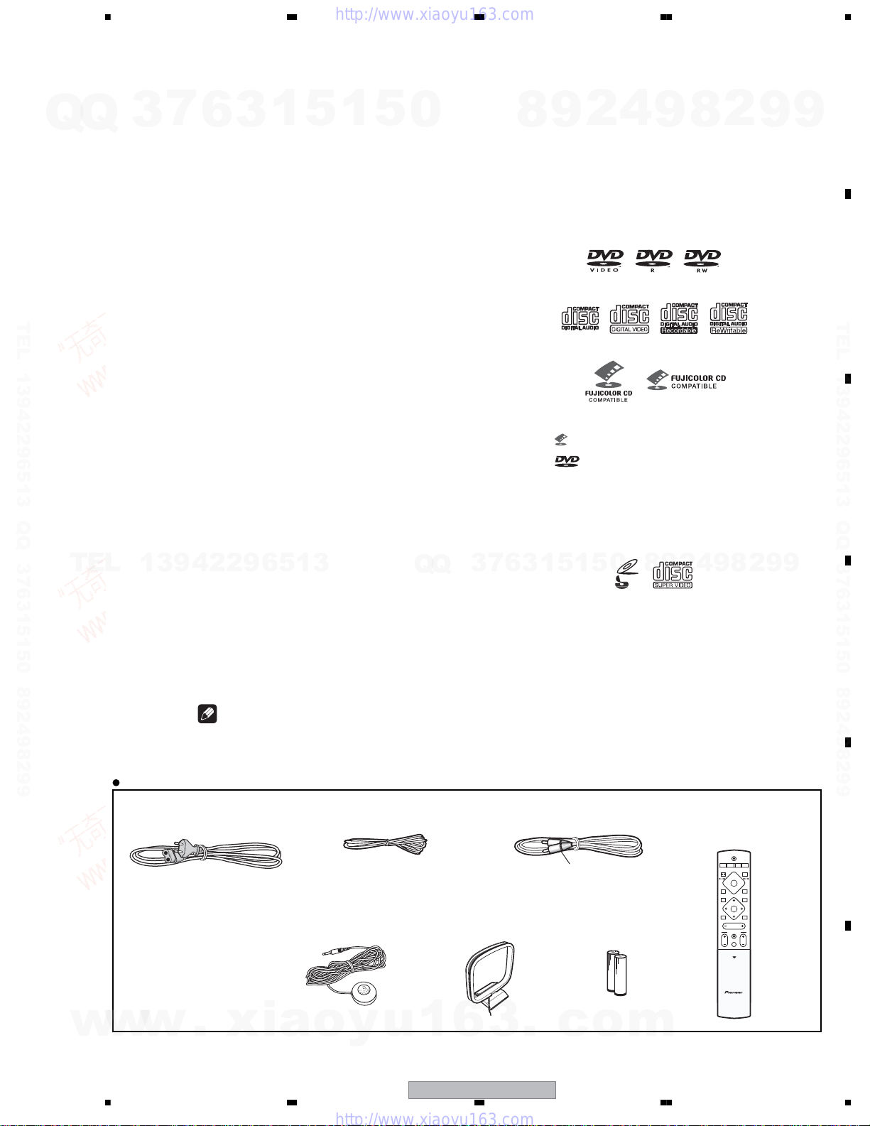
• Accessories (DVD/CD receiver)
Remote control . . . . . . . . . . . . . . . . . . . . . . . . . . 1
Microphone (for Auto MCACC setup) . . . . . . . . . 1
AA/R6 dry cell batteries . . . . . . . . . . . . . . . . . . . 2
Video cable (yellow plugs) . . . . . . . . . . . . . . . . . . 1
AM loop antenna . . . . . . . . . . . . . . . . . . . . . . . . . 1
FM antenna . . . . . . . . . . . . . . . . . . . . . . . . . . . . . 1
Power cord . . . . . . . . . . . . . . . . . . . . . . . . . . . . . 1
Setup Guide . . . . . . . . . . . . . . . . . . . . . . . . . . . . 1
Operating instructions . . . . . . . . . . . . . . . . . . . . 1
Note
• Specifications and design subject to
possible modification without notice, due
to improvements.
1
3
(±0.001 % W.PEAK) or less (JEITA)
(1 kHz, 10 % T.H.D., 6 Ω)
5
1
5
0
system and Compact Disc
digital audio system
4 Hz to 22 kHz (48kHz sampling)
. . . . . . . . .
(YLXJ/NC, YPWXJ). . . . . 0.6 W
7
3
Q
Q
Manufactured under license from Dolby
Laboratories.“Dolby”, “Pro Logic” and the doubleD symbol are trademarks of Dolby Laboratories.
“DTS” and “DTS Digital Surround” are registered
trademarks of Digital Theater Systems, Inc.
• FM Antenna (ADH7030)
• Microphone (APM7006) • AM Loop Antenna
(ATB7013)
Disc / content format playback
compatibility
This player is compatible with a wide range of
9
8
disc types (media) and formats. Playable discs
will generally feature one of the following logos
on the disc and/or disc packaging. Note
however that some disc types, such as
recordable CD and DVD, may be in an
unplayable format.
See the Disc compatibility tablebelow for more
information.
Audio CD CD-R
• is a trademark of Fuji Photo Film Co. Ltd.
• is a trademark of DVD Format/Logo
Licensing Corporation
Also compatible with KODAK Picture CD
This player supports the IECís Su per VCD standard for superior picture quality, dual
soundtracks, and widescreen support.
1
5
1
3
6
• Video Cable
(L = 1.5m) (XDE3046)
Yellow
• Dry Cell Batteries
4
2
DVD-Video DVD-R DVD-RW
Video CD
Fujicolor CD
8
0
5
VIDEO
CD
Super Video CD (Super VCD)
8
9
CD-RW
9
4
2
9
• Remote Control
(XV-DV333 : XXD3093)
(XV-DV434 : XXD3093)
(XV-DV535 : XXD3095)
2
8
STANDBY/ON
CD FM/AM
DVD TUNER TV LINE
FRONT
SURROUND
1
4
7
DVD MENU
TUNE+
ST-
ENTER
TUNE-
MUTE
MASTER
VOLUME
TV CONTROL
CH VOL
INPUT
OPEN
OPEN CLOSE
¡83
ST+
L1/L2
0
RETURN
BASS
MODE
2
4
9
9
A
9
B
TEL 13942296513 QQ 376315150 892498299
C
9
D
E
w
w
w
.
xia
56
o
y
u
1
6
XV-DV333
3
.
c
7
o
F
m
5
8
1234
2. EXPLODED VIEWS AND PARTS LIST
NOTES:
A
Q
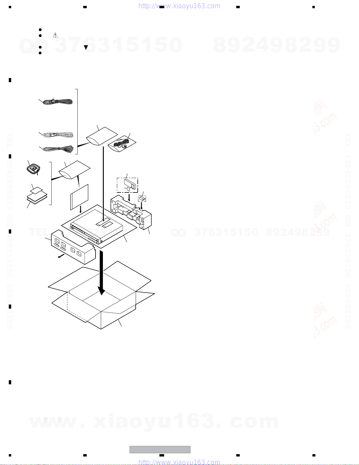
2.1 PACKING
B
TEL 13942296513 QQ 376315150 892498299
C
Parts marked by "NSP" are generally unavailable because they are not in our Master Spare Parts List.
The mark found on some component parts indicates the importance of the safety factor of the part.
Therefore, when replacing, be sure to use parts of identical designation.
Screws adjacent to mark on product are used for disassembly.
Q
For the applying amount of lubricants or glue, follow the instructions in this manual.
(In the case of no amount instructions, apply as you think it appropriate.)
1
6
2
4
7
3
18
7
6
3
18
1
16
5
3
15
1
5
5
0
8
9
2
4
9
8
2
9
9
TEL 13942296513 QQ 376315150 892498299
8,9
TEL
20
D
E
13942296513
Front side
22
19
21
Q
Q
3
7
6
3
1
5
1
5
0
8
9
2
4
9
8
2
9
9
F
w
w
w
6
1234
.
xia
o
y
u
1
6
XV-DV333
3
.
c
o
m
Q
>
>
5678
(1) PACKING SECTION PARTS LIST
No. Description Part No.
Mark
1Power Cord See Contrast table(2)
2 FM Antenna ADH7030
3 Microphone APM7006
7
Q
3
4 AM Loop Antenna ATB7013
NSP 5 Dry Cell Batteries(R6P,AA) VEM1031
6
(for Auto MCACC setup)
3
1
5
1
5
0
No. Description Part No.
Mark
16 Battery Cover XZN3130
17 • • • • • •
NSP 18 Polyethylene Bag Z21-038
9
8
(0.03*230*340)
19 Packing Sheet AHG7010
20 Front Pad XHA3152
2
4
9
8
2
9
A
9
6 Video Cable XDE3046
NSP 7 Warranty Card See Contrast table(2)
8 Operating Instructions See Contrast table(2)
9 Setup Guide See Contrast table(2)
10 • • • • • •
TEL 13942296513 QQ 376315150 892498299
TEL
11 • • • • • •
12 • • • • • •
13 • • • • • •
14 • • • • • •
15 Remote Control See Contrast table(2)
(2) CONTRAST TABLE
XV-DV333/MLXJ, YLXJ/NC, YPWXJ, XV-DV434/MLXJ, YLXJ/NC, YPWXJ, XV-DV535/MLXJ and YLXJ/NC are constructed
the same except for the following:
Mark No. Description
1Power Cord ADG1154 ADG1154 ADG7099 ADG1154 ADG1154 ADG7099 ADG1154 ADG1154
NSP 7 Warranty Card Not used Not used ARY7047 Not used Not used ARY7047 Not used Not used
8 Operating Instructions XRC3201 XRC3201 Not used XRC3201 XRC3201 Not used XRC3205 XRC3205
13942296513
(English/Chinese)
8 Operating Instructions Not used Not used XRB3052 Not used Not used XRB3052 Not used Not used
(English)
XV-DV333
/MLXJ
XV-DV333
/YLXJ/NC
Q
XV-DV333
/YPWXJ
Q
3
7
21 Rear Pad XHA3153
22 Packing Case See Contrast table(2)
XV-DV434
/MLXJ
3
6
1
5
XV-DV434
/YLXJ/NC
0
5
1
XV-DV434
/YPWXJ
2
9
8
XV-DV535
/MLXJ
8
9
4
XV-DV535
/YLXJ/NC
9
2
B
TEL 13942296513 QQ 376315150 892498299
C
9
w
w
9 Setup Guide XRE3099 XRE3099 Not used XRE3103 XRE3103 Not used XRE3106 XRE3106
(English/Chinese)
9 Setup Guide Not used Not used XRE3098 Not used Not used XRE3102 Not used Not used
(English/French)
15 Remote Control XXD3093 XXD3093 XXD3093 XXD3093 XXD3093 XXD3093 XXD3095 XXD3095
22 Packing Case XHD3546 XHD3509 XHD3511 XHD3520 XHD3518 XHD3522 XHD3527 XHD3525
w
.
xia
o
y
u
1
6
3
.
c
o
m
D
E
F
56
XV-DV333
7
7
8
1234
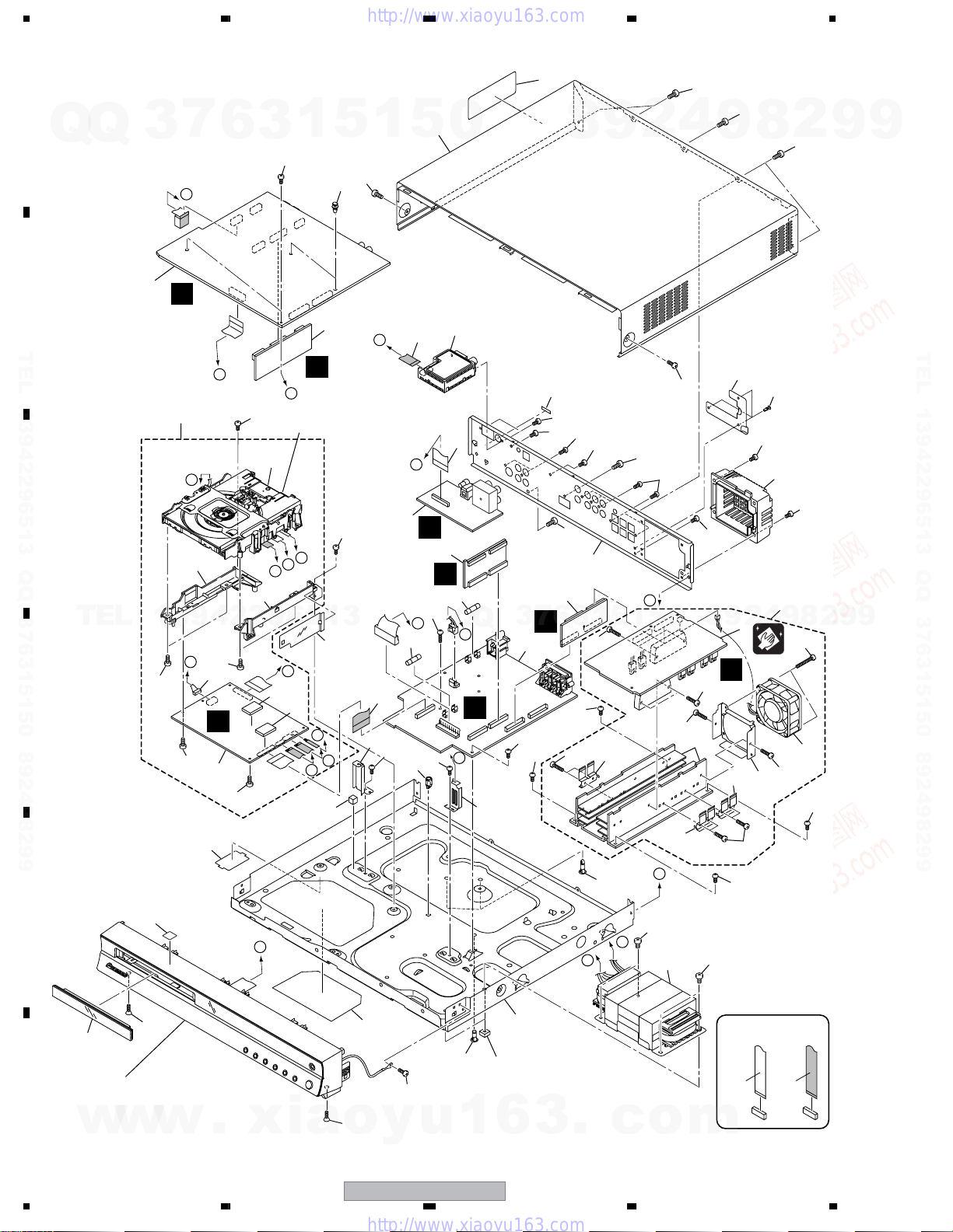
2.2 EXTERIOR SECTION
A
Q
Q
3
1
7
I
6
3
46
1
5
18
1
48
17
5
0
F
B
2
TEL 13942296513 QQ 376315150 892498299
A
27
K
C
29
TEL
D
13942296513
K
50
50
49
30
50
31
B
3
50
C
H
Refer to
"2.4 05 LOADER ASSY."
28
D
C
B
33
J
32
32
D
C
B
36
49
35
I
7
11
16
46
34
14
9
15
J
I
6
E
10
55
E
Q
F
Q
3
7
4
J
46
46
H
35
49
45
8
MLXJ only
57
46
46
46
5
3
6
G
49
52
47
22
46
1
52
9
5
26
56
1
2
47
G
5
4
48
0
52
25
48
52
46
8
48
9
20
9
D
26
8
Except
YPWXJ
19
46
21
23
4
2
8
Cleaning paper
GED-008
24
9
52
2
48
46
8
51
13
49
9
2
9
9
TEL 13942296513 QQ 376315150 892498299
9
37
38
E
43
F
w
8
YPWXJ only
58
A
40
6
39
3
.
54
Refer to
"2.3 FRONT PANEL SECTION."
w
w
1234
.
xia
42
41
46
54
o
y
u
1
XV-DV333
F
E
c
26
G
53
12
o
53
m
x4
52
49
NON-CONTACT
SIDE
CONTACT SIDE
Q
5678
(1) EXTERIOR SECTION PARTS LIST
No. Description Part No.
Mark
1 CONTROL Assy See Contrast table(2)
2 DSP Assy AWX8587
3DVDM Assy AWM7962
Q
7
3
4POWER Assy XWZ3975
5 TRADE1 Assy XWZ3997
6
3
1
>
>
>
>
5
1
5
0
No. Description Part No.
Mark
31 Connector Assy PG05KK-E07
32 Cushion AEB7267
33 Barrier VK1 AEC7533
9
8
NSP 34 Spacer PNY-404
35 Control Angle XNG3108
2
4
9
8
2
9
A
9
6 TRADE2 Assy XWZ3998
7 VIDEO Assy XWZ3980
86 CH AMP XWK3188
9 FM/AM TUNER Unit AXX7173
10 Fuse (FU1: T2.5A) REK1026
11 Fuse (FU2: T5.0A) REK1029
TEL 13942296513 QQ 376315150 892498299
TEL
12 Power Transformer (T1) See Contrast table(2)
13 DC Fan Motor XXM3009
14 11P F.F.C/60V XDD3152
15 27P F.F.C/60V XDD3188
16 25P F.F.C/60V XDD3157
17 Bonnet Case XZN3160
NSP 18 PCB Spacer(3X6) AEC7156
19 Push Rivet See Contrast table(2)
20 Fan Barrier See Contrast table(2)
21 Fan Cover XMR3086
22 Rear Panel See Contrast table(2)
NSP 23 AMP Unit 6ch XXQ3004
24 Fan Plate ANG7462
NSP 25 Heat Sink XNH3038
13942296513
26 FET Bracket A ANG7418
NSP 27 DVD Assy AXA7145
NSP 28 05 LOADER Assy VWT1219
29 Adaptor 05L ANW7282
30 Adaptor 05R ANW7283
Q
Q
3
7
36 PCB Spacer AEB7206
37 Bottom Plate XEC3058
38 Locking Card Spacer AEC7372
NSP 39 Chassis XNA3024
40 S Cover AEB7262
41 Card Spacer DNK2769
42 Name Label XAX3454
43 Tray Cap Assy See Contrast table(2)
44 • • • • • •
45 Caution Label VRW1872
46 Screw BBZ30P060FTC
47 Screw VPZ30P100FTC
48 Screw BBZ30P080FNI
49 Screw VBZ30P080FTC
50 Screw BPZ30P080FNI
51 Screw BBZ30P300FTC
52 Screw BBZ30P140FTC
53 Screw BBZ40P060FTC
54 Screw CBZ30P080FTC
55 Screw VPZ30P140FTC
5
1
3
6
56 Screw PPZ30P080FNI
NSP 57 SISIR Label See Contrast table(2)
NSP 58 Energy Star Label See Contrast table(2)
1
5
0
8
9
2
4
9
8
2
9
9
B
TEL 13942296513 QQ 376315150 892498299
C
D
(2) CONTRAST TABLE
XV-DV333/MLXJ, YLXJ/NC, YPWXJ, XV-DV434/MLXJ, YLXJ/NC, YPWXJ, XV-DV535/MLXJ and YLXJ/NC are constructed
the same except for the following:
Mark No. Description
1 CONTROL Assy XWZ3969 XWZ3969 XWZ3969 XWZ3984 XWZ3984 XWZ3984 XWZ3989 XWZ3989
12 Power Transformer (T1) XTS3077 XTS3078 XTS3078 XTS3077 XTS3078 XTS3078 XTS3077 XTS3078
19 Push Rivet XEC3034 XEC3034 Not used XEC3034 XEC3034 Not used XEC3034 XEC3034
20 Fan Barrier XMR3089 XMR3089 Not used XMR3089 XMR3089 Not used XMR3089 XMR3089
22 Rear Panel XNC3351 XNC3357 XNC3340 XNC3367 XNC3368 XNC3372 XNC3354 XNC3353
43 Tray Cap Assy XXG3207 XXG3207 XXG3207 XXG3207 XXG3207 XXG3207 XXG3211 XXG3211
NSP 57 SISIR Label XAX3513 Not used Not used XAX3514 Not used Not used XAX3515 Not used
NSP 58 Energy Star Label Not used Not used AAX8022 Not used Not used AAX8022 Not used Not used
w
w
w
.
xia
56
XV-DV333
/MLXJ
o
XV-DV333
/YLXJ/NC
y
u
XV-DV333
/YPWXJ
1
6
3
XV-DV333
XV-DV434
/MLXJ
.
XV-DV434
/YLXJ/NC
c
o
7
XV-DV434
/YPWXJ
m
XV-DV535
/MLXJ
XV-DV535
/YLXJ/NC
E
F
9
8
1234
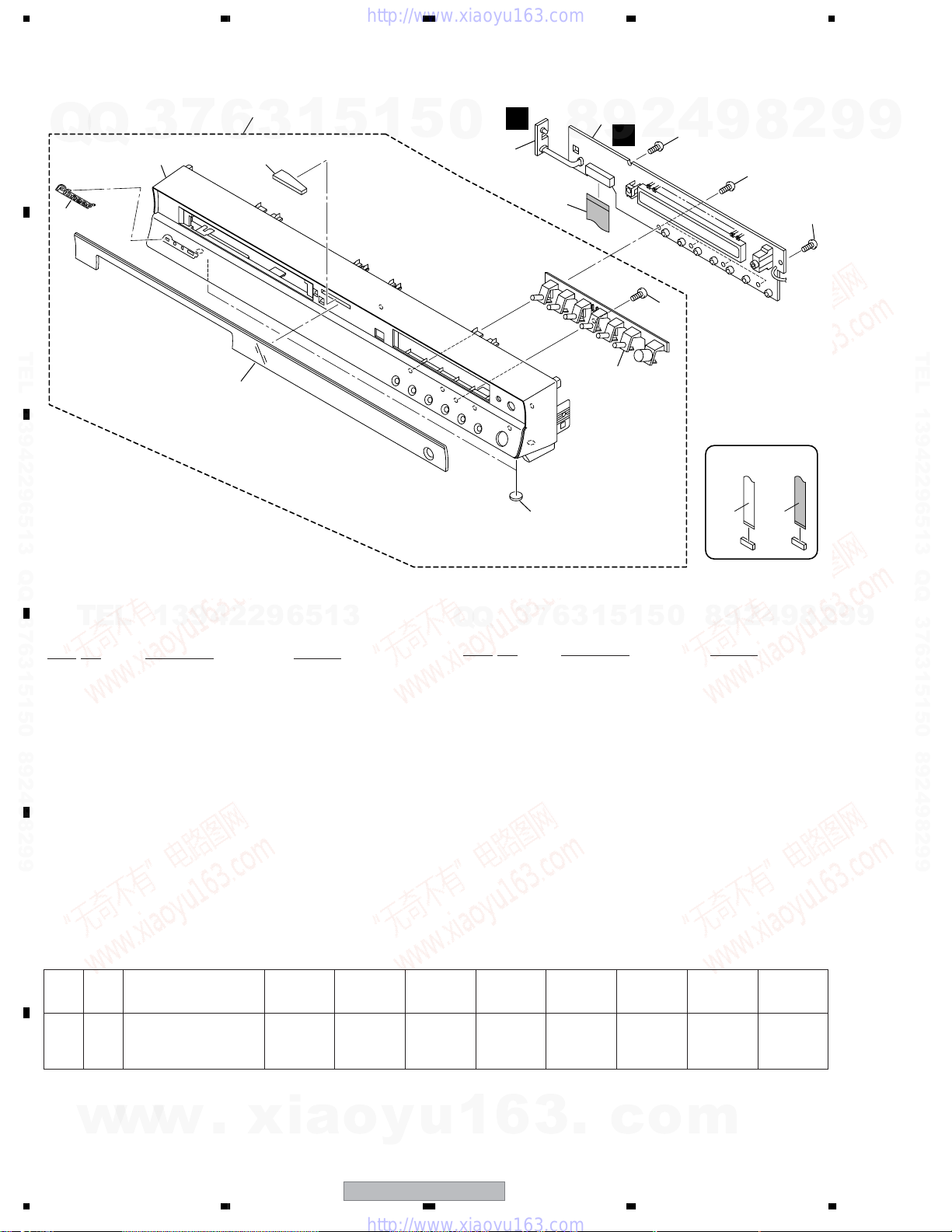
2.3 FRONT PANEL SECTION
6
8
4
3
7
1
5
1
5
0
K
2
9
A
7
Q
Q
6
B
TEL 13942296513 QQ 376315150 892498299
C
3
5
8
3
1
9
H
10
2
11
12
4
9
2
8
12
12
NON-CONTACT
SIDE
CONTACT SIDE
9
9
TEL 13942296513 QQ 376315150 892498299
TEL
(1) FRONT PANEL SECTION PARTS LIST
No. Description Part No.
Mark
1 DISPLAY Assy XWZ3979
2 LED Assy XWZ4000
D
E
3 19P F.F.C/60V XDD3158
NSP 4 Front Panel Assy See Contrast table(2)
5Front Panel See Contrast table(2)
6 Pioneer Name Plate VAM1129
7 Illumination Lens AAK8214
8 Display Window See Contrast table(2)
9 Leg AEB7090
10 FUNC. Button XAD3209
(2) CONTRAST TABLE
XV-DV333/MLXJ, YLXJ/NC, YPWXJ, XV-DV434/MLXJ, YLXJ/NC, YPWXJ, XV-DV535/MLXJ and YLXJ/NC are constructed
the same except for the following:
Mark No. Description
NSP 4 Front Panel Assy XXG3225 XXG3225 XXG3225 XXG3227 XXG3227 XXG3227 XXG3229 XXG3229
5Front Panel XMB3207 XMB3207 XMB3207 XMB3208 XMB3208 XMB3208 XMB3209 XMB3209
8 Display Window XAK3485 XAK3485 XAK3485 XAK3485 XAK3485 XAK3485 XAK3487 XAK3487
13942296513
XV-DV333
/MLXJ
XV-DV333
/YLXJ/NC
Q
XV-DV333
/YPWXJ
8
0
5
1
5
1
3
6
7
3
Q
No. Description Part No.
Mark
11 Screw BPZ30P080FTC
12 Screw VPZ30P100FTC
XV-DV434
/MLXJ
XV-DV434
/YLXJ/NC
XV-DV434
/YPWXJ
XV-DV535
/MLXJ
9
4
2
XV-DV535
/YLXJ/NC
9
8
2
9
9
F
w
w
w
10
1234
.
xia
o
y
u
1
6
XV-DV333
3
.
c
o
m
5678
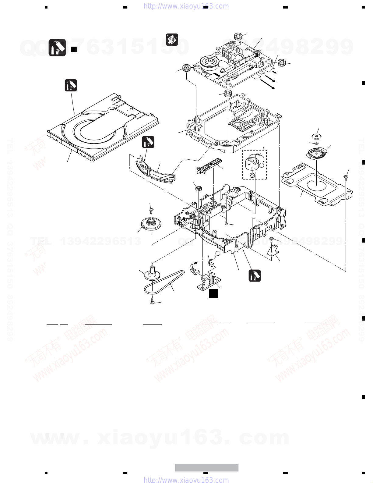
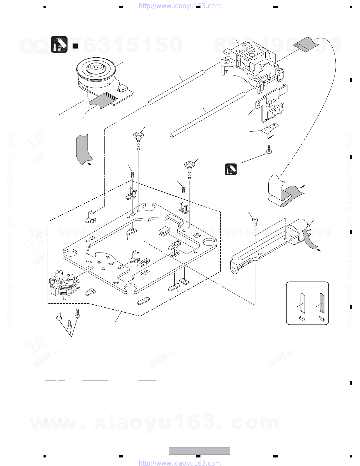
2.4 05 LOADER ASSY
Note :
Refer to
" Application of Lubricant".
7
Q
Q
TEL 13942296513 QQ 376315150 892498299
3
23
6
Daifree
GEM1036
3
1
5
1
5
Lubricating Oil
GYA1001
13
22
Pickup leneses
Cleaning liquid
GEM1004
Cleaning paper
GED-008
0
8
12
16
8
8
17
9
8
2
Refer to
"2.5 Traverse Mechanism Assy-S".
4
2
A
6
3
8
9
8
To DVDM CN101 (Pickup)
To DVDM CN104 (Stepping Motor)
To DVDM CN102 (Spindle Motor)
24
19
2
18
9
20
A
9
B
TEL 13942296513 QQ 376315150 892498299
22
C
TEL
13942296513
05 LOADER ASSY PARTS LIST
No. Description Part No.
Mark
NSP 1 LOAB Assy VWG2346
2Traverse Mechanism Assy-S DXX2568
3 Loading Motor Assy VXX2912
4• • • • •
5• • • • •
6 Flexible Cable (24P) VDA2008
7 Connector Assy 2P VKP2253
8 Floating Rubber VEB1351
9 Belt VEB1358
10 Stabilizer VNE2253
15
14
22
Q
Q
To
DVDM CN103
9
3
21
22
4
2
9
8
0
5
1
5
1
3
6
7
7
A
10
11
1
A
No. Description Part No.
Mark
16 Drive Gear VNL1923
17 SW Lever VNL1925
18 Clamper Plate 04 VNE2342
19 Bridge 04 VNE2343
20 Clamper 04 VNL1969
21 Screw JGZ17P028FTC
22 Screw VBA1094
23 Tray VNL1920
24 Clamp Magnet VMG1029
Lubricating Oil
GYA1001
9
8
2
9
9
D
E
w
w
11 Loading Base VNL1917
12 Float Base 04 VNL1968
13 Drive Cam VNL1919
14 Gear Pulley VNL1921
w
15 Loading Gear VNL1922
.
xia
56
o
y
u
1
6
3
XV-DV333
.
c
7
o
F
m
11
8
1234
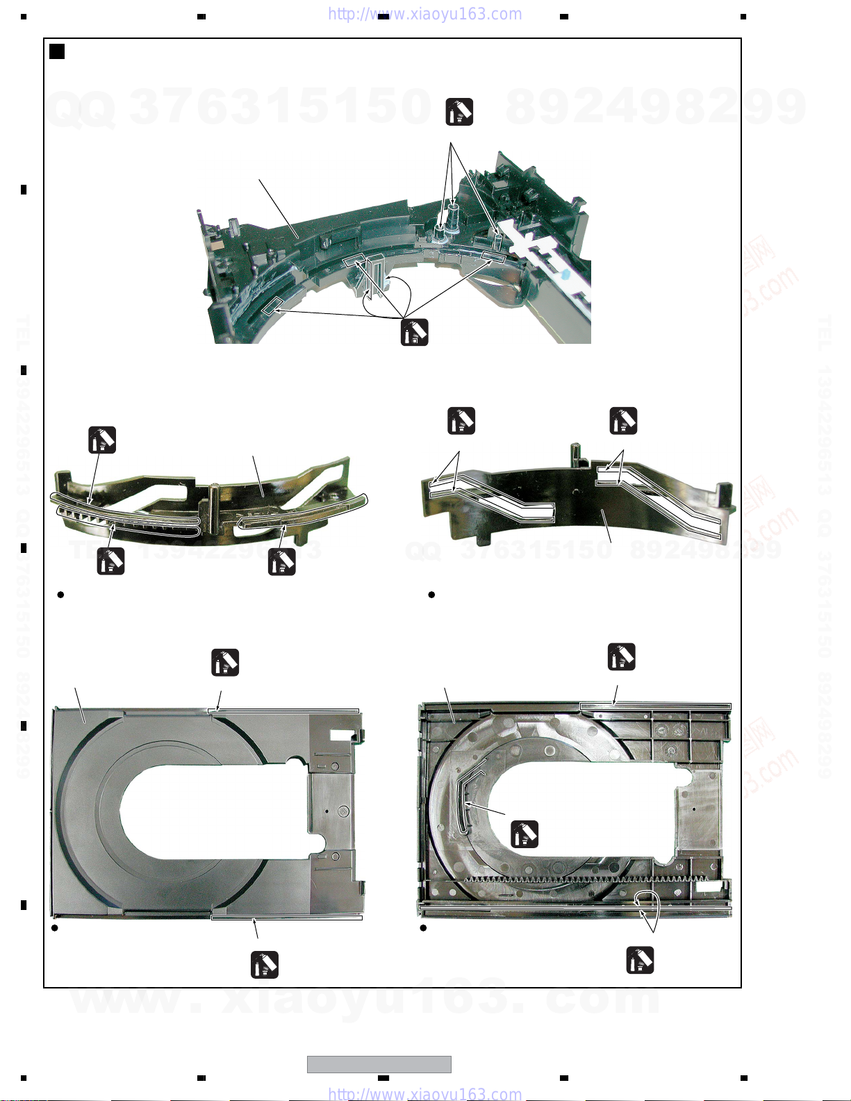
Application of Lubricant
A
7
Q
Q
B
TEL 13942296513 QQ 376315150 892498299
C
3
Lubricating Oil
GYA1001
6
1
3
No. 11
Loading Base
No. 13
Drive Cam
5
1
5
0
Lubricating Oil
GYA1001
Lubricating Oil
GYA1001
Around the shaft
Lubricating Oil
GYA1001
Inner side of a ditch
8
9
4
2
Inner side of a ditch
8
9
Lubricating Oil
GYA1001
2
9
9
TEL 13942296513 QQ 376315150 892498299
TEL
Front View Rear View
D
No. 23
Tray
E
Top View Bottom View
F
w
13942296513
Lubricating Oil
GYA1001
Daifree
GEM1036
Concave of unevenness
w
w
.
xia
Lubricating Oil
GYA1001
Concave of unevenness
Daifree
GEM1036
o
y
Q
u
Q
1
3
No. 23
Tray
6
1
3
6
7
Inner side of a ditch
3
.
5
1
5
Daifree
GEM1036
c
o
No. 13
8
0
Drive Cam
Daifree
GEM1036
Concave of unevenness
Side of the rib
2
9
Daifree
GEM1036
4
m
9
8
2
9
9
12
XV-DV333
1234
5678
2.5 Traverse Mechanism Assy-S
>
Note :
Refer to
" Application of Lubricant".
7
Q
Q
TEL 13942296513 QQ 376315150 892498299
3
6
To DVDM CN102
(Spindle Motor)
3
1
5
1
5
Note : When part #2 is replaced,
2
11
part #13 also need to be
replaced at the same time.
10
0
4
11
3
10
8
1
2
9
5
6
Silicone Adhesive
GEM1037
4
9
9
8
2
DVDM CN101
(Pickup Assy)
9
To
A
9
B
TEL 13942296513 QQ 376315150 892498299
C
TEL
w
13942296513
8
Note : Spindle screw (DBA1252) of No.13 is the screw which applied special bond.
13
Traverse Mechanism Assy-S PARTS LIST
No. Description Part No.
Mark
1 05SD Pickup Assy-S OXX8014
2 Spindle Motor N200 DXM1197
3 Guide Shaft VK1 DLA1940
4 Sub Guide Shaft VK1 DLA1941
NSP 5 Joint VK1B DNK4272
w
w
6 Joint Spring VK1 DBK1235
7 Stepping Motor VK1 DXM1201
Therefore the adhesion becomes ineffective when takes it off once. Spindle screw is the part which cannot recycle.
When part #2 is replaced, part #13 also need to be replaced at the same time.
.
xia
o
y
u
Q
Q
1
12
9
8
0
5
1
5
1
3
6
7
3
Mark No. Description Part No.
NSP 8 Mechanism Frame VK1 DNK4160
9 Precision Screw VK1 DBA1209
10 Skew Screw VK1 DBA1211
11 Skew Spring VK1 DBH1516
NSP 12 Stepping Screw DBA1205
6
3
.
c
o
13 Spindle Screw VK1(for Service) DBA1252
m
9
4
2
NON-CONTACT
SIDE
7
9
2
8
DVDM CN104
(Stepping Motor)
CONTACT SIDE
9
To
D
E
F
56
XV-DV333
13
7
8
1234
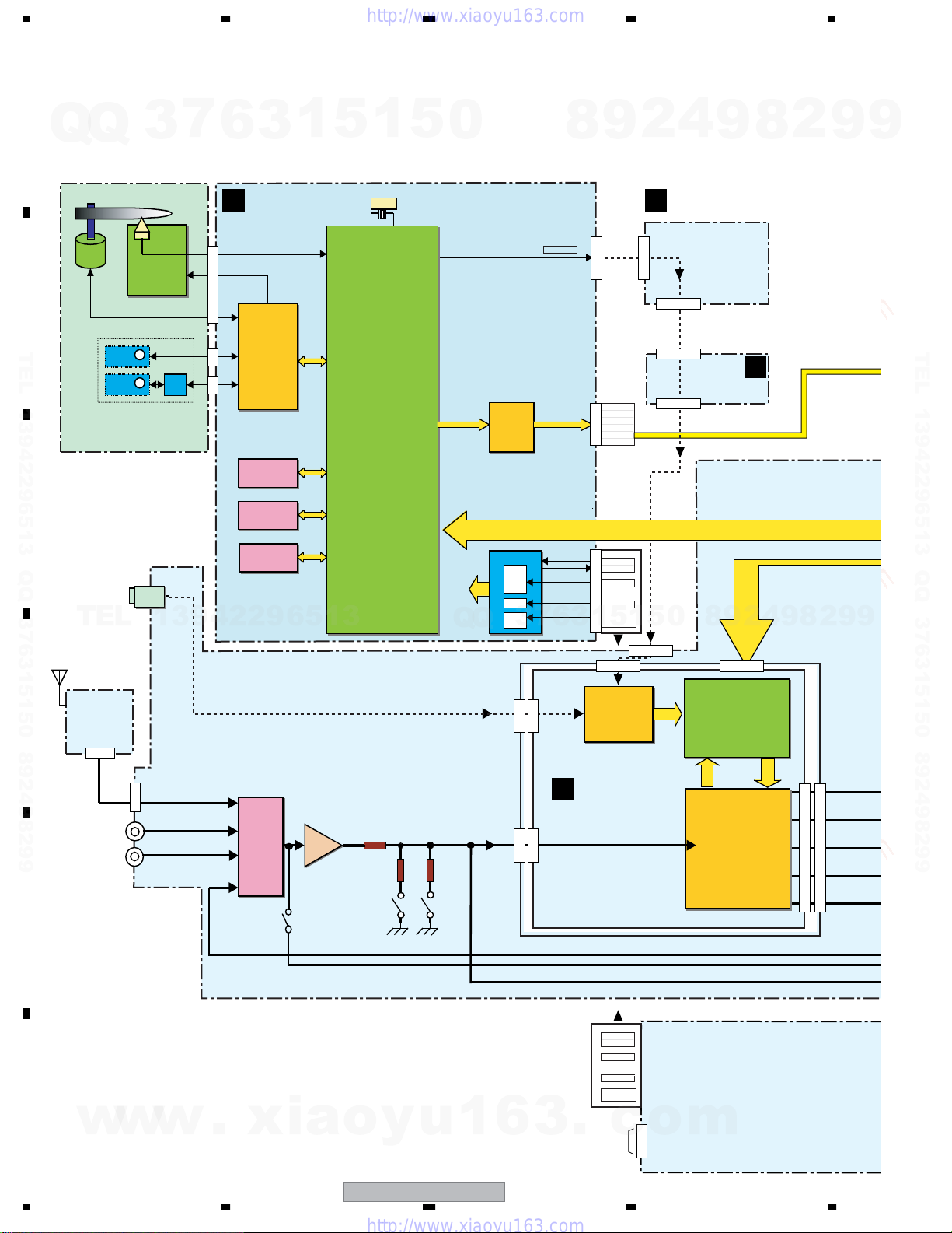
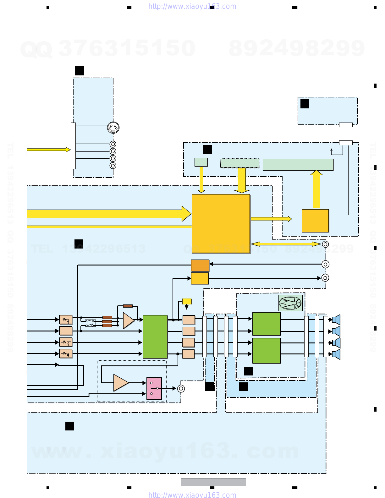
3. BLOCK DIAGRAM AND SCHEMATIC DIAGRAM
3.1 BLOCK DIAGRAM
A
Q
Q
3
7
6
3
1
5
1
5
0
8
9
2
4
9
8
2
9
9
B
DVDM ASSY
Loading
Motor
Stepping
Motor
04SD PU
PlCK UP
ASSY
IC101
BD7995EFS
FTS &
SPDL DRlVER
IC202
64M SDRAM
IC203
16M
FLASH ROM
IC204
16K
EEPROM
+ -
+ -
M
LOAB
M
Ass'y
13942296513
IC3001
INPUT
SELECTOR
BUFFER
IC3003
SPINDLE
Motor
VK-1
B
TEL 13942296513 QQ 376315150 892498299
C
LINE 2 IN
(OPT DIGITAL)
TEL
D
FM/AM
TUNER
UNIT
LINE 1
IN
TV IN
27MHz
IC201
MT1389FE/C2-L-K
BACK END IC
• RF Amp
• Servo control
• Systemcontrol CPU
• AV decoder
• 108MHz 12bit Video DAC
ATTENUATOR
- 6dB - 10dB
Q
IC401
MM1623BF
VlDEO AMP
DRlVER
POWER SUPPLY
Q
1.8V
3.3V
5V
6.8V
12V
3
4
CN5613
313
7
4
1
DOUT
6
CN5613
DIN
CN901
C
LIN
RIN
CN901
3
CN901
##
CN903
V
SY
SC
CY/G
Cb/B
Cr/R
CN901
VDET
VPR+8
VPR+8M
VDVD+12
1
5
1
2
IC601
AK4117VF
DIR
DSP ASSY
J
POWER ASSY (2/2)
CN5102
CN5532
4
TRADE2 ASSY (2/2)
4
CN5522
E
CN5512
&
2
9
8
0
5
CN5502
&
IC801
DSPC56371AF180
• Dolby Digital Decoder
• Dolby PrologicII
• DTS Decoder
IC701
AK4628VQE
8ch
CODEC
4
CN5620
CN951
9
8
CN701
2
CN5612
9
TEL 13942296513 QQ 376315150 892498299
9
CN701
E
F
w
w
w
14
1234
.
xia
o
y
u
1
XV-DV333
CN5612
6
3
.
VDET
VPR+8
VPR+8M
VDVD+12
c
AC IN
CN5102
o
1
LIVE
2
NEUTRAL
CN3101
m
Q
Q
3
5678
7
6
I
VIDEO ASSY
3
1
5
1
5
0
8
9
2
4
9
8
K
LED ASSY
2
9
A
9
CN8801
TEL 13942296513 QQ 376315150 892498299
F
TEL
13942296513
Y
C
Y
Cb
Cr
V
CONTROL ASSY
S-VIDEO
OUT
CN8802
COMPONENT&
COMPOSITE
VIDEO OUT
JA8851
DTS,LFE
MIX/GAIN
JA101
IR
SENSOR
Q
Q
MICAMP
Headphone
AMP
ANDREW BYPASS
H
DISPLAY ASSY
PDC122
IC5501
micro
Processoer
7
3
KEY
6
3
1
5
1
5
0
FAN
FL Tube
8
9
2
IC5601
FL
Driver IC
PT6302
9
4
J5602
J5601
VFL+5
SR PLUS
2
8
MCACC
HEADPHONE
12
12
9
VFL+5
LED
9
B
TEL 13942296513 QQ 376315150 892498299
C
D
FL/FR
SW
Centre
SL/SR
REC OUT
w
w
+0dB
LPF
+0dB
+0dB
IC3002
J
POWER SUPPLY ASSY (1/2)
w
.
xia
56
+
WIRE LESS MODEL ONLY
+6dB
IC3062
BD3814FV
E-VOL
• 6ch E-vol
WIRELESS OUT
SELECT
IC9091
o
y
u
ANDREW
WIRELESS
OUT
TRADE2
ASSY
(1/2)
1
CN5521
CN5511
CN5501
E
6
3
XV-DV333
CN3032
CN5531
CN3012
CN3022
.
IC3301
STK433-270
• 3ch Power Amp
IC3401
STK433-270
• 3ch Power Amp
CN3002
H
AMP UNIT 6CH
TRADE1 ASSY
G
c
o
7
m
CN3001
CN3011
CN3021
CN3031
8
FL/FR
OUT
SW
OUT
CENTRE
OUT
SL/SR
OUT
E
F
15
1234
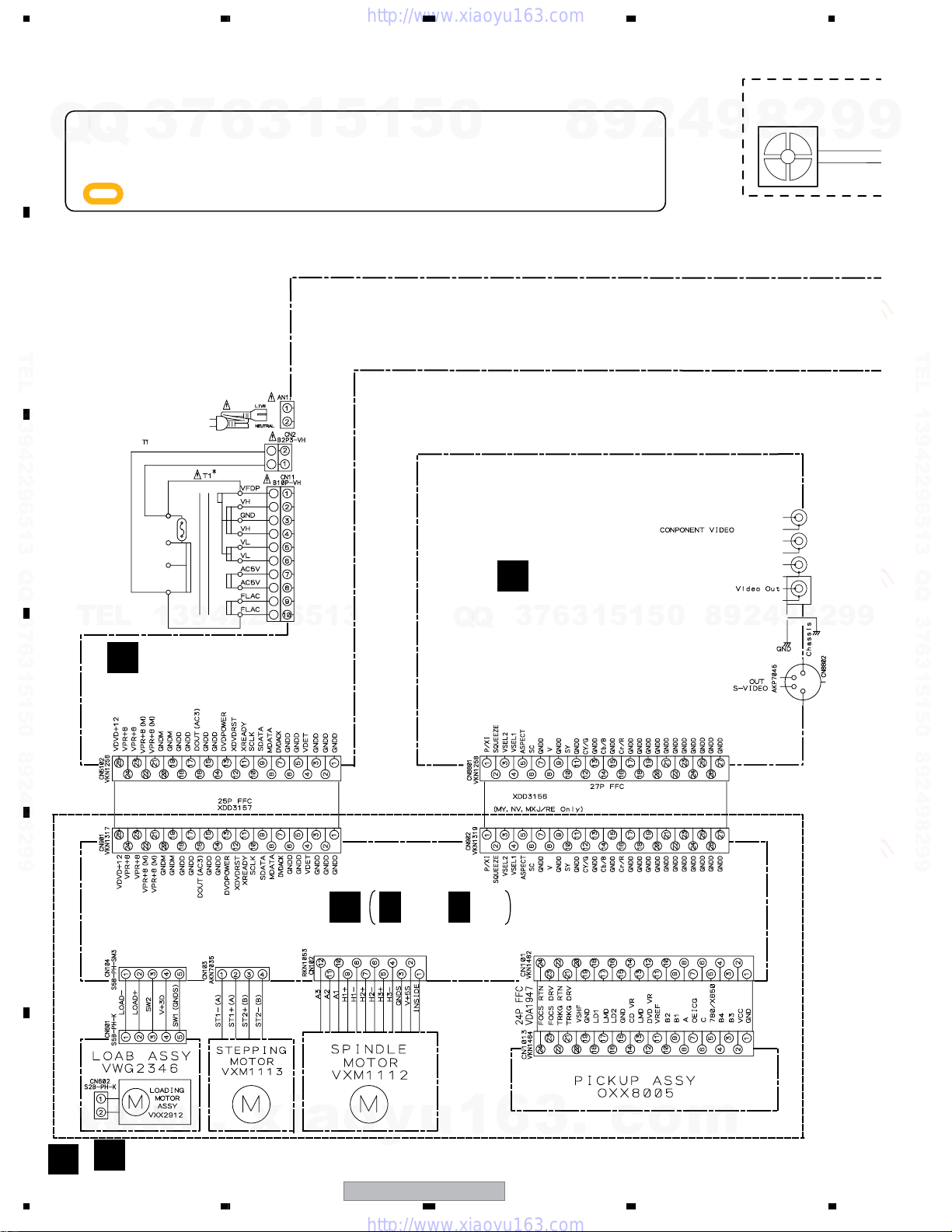
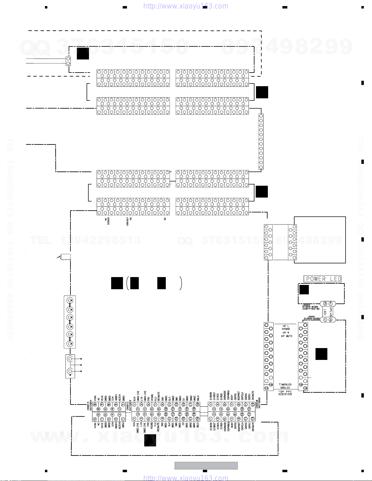
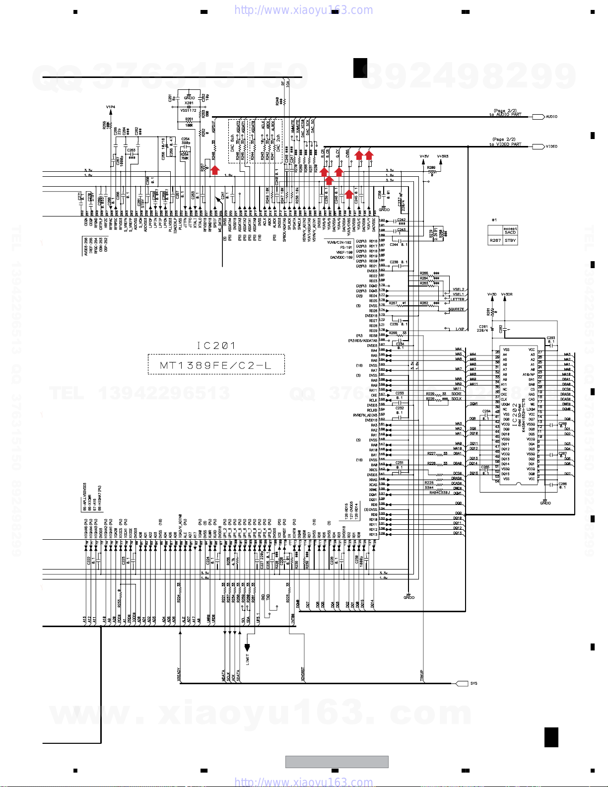
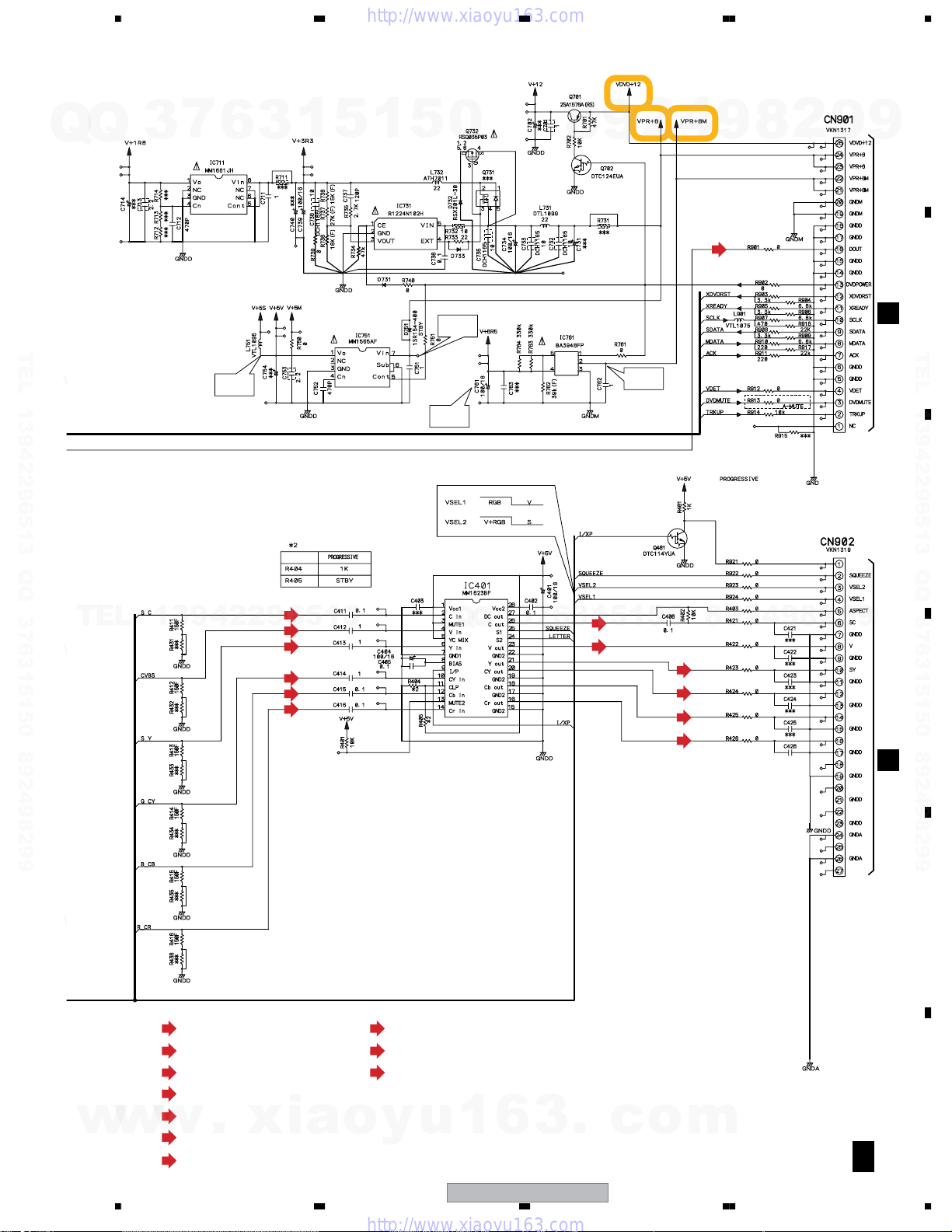
3.2 OVERALL WIRING CONNECTION DIAGRAM
A
B
TEL 13942296513 QQ 376315150 892498299
C
÷
When ordering service parts, be sure to refer to "EXPLODED VIEWS and PARTS LIST" or
Q
Q
"PCB PARTS LIST".
÷
The > mark found on some component parts indicates the importance of the safety factor
of the part. Therefore, when replacing, be sure to use parts of identical designation.
÷
TEL
: The power supply is shown with the marked box.
7
3
MLXJ : XTS3077
YLXJ/NC, YPWXJ : XTS3078
13942296513
6
3
XKP3084
1
5
1
5
0
Q
Q
VIDEO ASSY
I
(XWZ3980)
7
3
6
8
3
9
1
5
1
2
5
4
0
9
8
9
8
2
YGND
YGND
CbGND
4
FAN
2
1
Y
2
1
Cb
2
3
Cr
JA8851
4
5
6
GND
2
8
9
9
9
9
TEL 13942296513 QQ 376315150 892498299
9
J
POWER ASSY(XWZ3975)
D
E
F
w
w
16
A
w
LOAB ASSY
A
(VWG2346)
1234
.
xia
B
DVDM ASSY (AWM7964)
B 1/2- B 2/2
o
y
u
1
6
XV-DV333
DVD ASSY (AXA7145)
3
.
c
o
m
5678
AMP UNT 6CH (XXQ3004)
CN3501
KM200SA2
Q
Q
3
FAN-
FAN+
7
2
1
6
6CH AMP (XWK3188)
D
XKP3071
CN3001
XKP3082
CN3011
XKP3082
CN3021
CN3031
XKP3071
3
VH-
VH-
1
3
246
2
1
3
1
3
2
2
1
3
VH-
VH-
FROUT
FROUT
4
4
FROUT
4
1
GNDP
FROUT
GNDP7FLOUT
5
56789
56789
56789
GNDP
GNDP
FLOUT
FLOUT
8
FLOUT
GNDS
9
GNDS
SWOUT
5
SWOUT
SWOUT
VH+
11
12
10
10
111213
111213
10
10
111213
VH+
SWOUT
13
VH+
VH+
COUT
COUT
14
14
14
14
COUT
15
15
15
15
COUT
1
VL+
VL+
SROUT
17
18
16
18
16
17
17
181820
16
16
17
VL+
VL+
SROUT
SROUT
19
19
19
19
SROUT
20
20
20
VL-
5
VL-
VL-
SLOUT
21
22
22
21
21
22
22
21
VL-
SLOUT
SLOUT
SLOUT
23
23
23
23
0
GNDF
17325
XKP3071
CN3002
1
XKP3082
CN3012
XKP3082
CN3022
1
XKP3071
CN3032
GNDF
2
2
UN+8V
UN+8V
UN+8V
3
321
3
UN+8V
GNDREG
GNDREG
4
4
567
5
4
4
567
GNDREG
GNDREG
TUNER
XPROTECT
6
8
8
7
8
6
8
TUNER
XPROTECT
VD+5
VD+5
9
9
9
VA-12
VA-12
VP+15
10
10
10
VP+15
TEL 13942296513 QQ 376315150 892498299
DVDON/OFF
TEL
HPAC
VPR+8(VD+5)
RYRC
RYFS
VX+12
XPROTECT
VA-12
3
1
CN5531
XKP3071
2
1
XKP3082
CN5521
2
CN5511
XKP3082
2
1156789
3
CN5501
XKP3071
HPAC
VPR+8(VD+5)
4
325
3
4
4
567
56789
4
RYRC
6
RYFS
8
789
VX–12
9
VX+12
13942296513
JA8602
TORX179PL
OPT IN
DIGITAL
213
GNDX
GNDX
10
10
VD+5
10
VA+12
111213
111213
111213
111213
MUTEC
VD+5
MUTE
VA+12
14
14
GNDA
FLIN
15
141016
15
14
15
FLIN
16
16
GNDA
GNDA
16
GNDA
FRIN
171715
17
17
FRIN
NCNCSRIN
SLIN
SWIN
CIN
21
23
19
22
18
20
22
18
20
19
23
21
21
23
19
22
18
20
22
18
20
19
21
23
CIN
SLIN
SRIN
SWIN
VE+56
CN5532
XKP3071
XKP3082
CN5522
CN5512
XKP3082
CN5502
XKP3071
GNDD
1
GNDD
Q
GNDD
321
GNDD
DOUT
GNDD
325
4
4
321
4
4
32165
DOUT
GNDD
Q
GNDU
567
5
GNDU
VE+56
6
6
7
SUBAC
SUBAC
7
8
7
8
VFL+5
FLAC1
8
9
8
9
FLAC1
3
FLAC2
9
9
FLAC2
SYSPOW
10
10
10
GNDFL
111213
111213
7
VFL+5
111213
111213
11
121410
111213
VFL+5
VFDP
VFL+5
111213
111213
VFDP
MUTE
SENSE+8
MUTEC
13
MUTE
MUTEC
GNDFL
14
MUTEC
6
8
FLIN
MUTE
GNDA
FRIN
151419
17
16
14916
15
15
16
14
16
15
CIN
FLIN
FRIN
GNDA
GNDFL
VDET
MDATA
ACK
172019
15
16
14
16
15
17
17
14
1615201922
161014
15
SCLK
SDATA
MDATA
XPROTECT
3
CIN
18
181720
181720
SWIN
SDATA
18
18
19
18
181720
VDET
1
SCLK
19
9
SRIN
SWIN
SLIN
21
202322
20
22
191817
21
21
19
22
22
19
21
SLIN
SRIN
GNDA
NC
XDVDRST
XREADY
21
20
22
21
21
22
21
NC
SYSPOW
XDVDRST
DVDON/OFF
5
VPR+8
VPR+8
22
23
23
1
VPR+8
23
23
23
VPR+8
NC
23
23
NC
2
G
JA3301
XKE3036
E
5
4
9
8
2
TRADE 1 ASSY (XWZ3997)
+
FL
-
+
FR
-
+
SW
-
6ch SPEAKER OUT
+
C
-
+
SL
-
+
SR
-
TRADE 2 ASSY (XWZ3998)
CN5701
52045-1145
GND
0
11
RDS
10
VSM
9
TXR
8
+9V
7
6
TXL
GND
5
DO
4
CLK
3
DI
2
CE
1
8
11pinFFC
11
10
9
FM/AM TUNER
8
7
UNIT
6
4
2
9
5
(AXX7173)
4
3
2
1
* No schematic diagram
9
8
2
9
9
A
9
B
TEL 13942296513 QQ 376315150 892498299
C
9
w
w
JA3001
AKP7050
L
TV
R
L
LINE1LINEOUT
R
L
R
AKB1233
L
R
4
WIRELESS OUT
XV-DV535 only
w
JA9091
1
3
2
.
CN901
XKP3075
F 1/4- F 4/4
F
CONTROL ASSY
CN701
XKP3080
xia
o
(XWZ3969 : XV-DV333)
(XWZ3984 : XV-DV434)
(XWZ3989 : XV-DV535)
y
u
1
6
C DSP ASSY (AWX8587)
3
.
c
CN5611
52045-1545
1
2
3
4
5
6
7
8
9
10
11
12
13
14
15
16 16
17 17
CN951
XKP3077
o
m
HPDET
VFDP
XFLRST
FLCS
FLCK
FLDATA
VFL+5
GNDFL
FLAC2
FLAC1
KEY1
REMOCON
VFL+5
LED ASSY
K
(XWZ4000)
CN5601
1
52044-1545
2
3
4
5
6
7
8
9
10
11
12
13
14
15
H
DISPLAY ASSY
D
E
(XWZ3979)
F
56
XV-DV333
17
7
8
1234
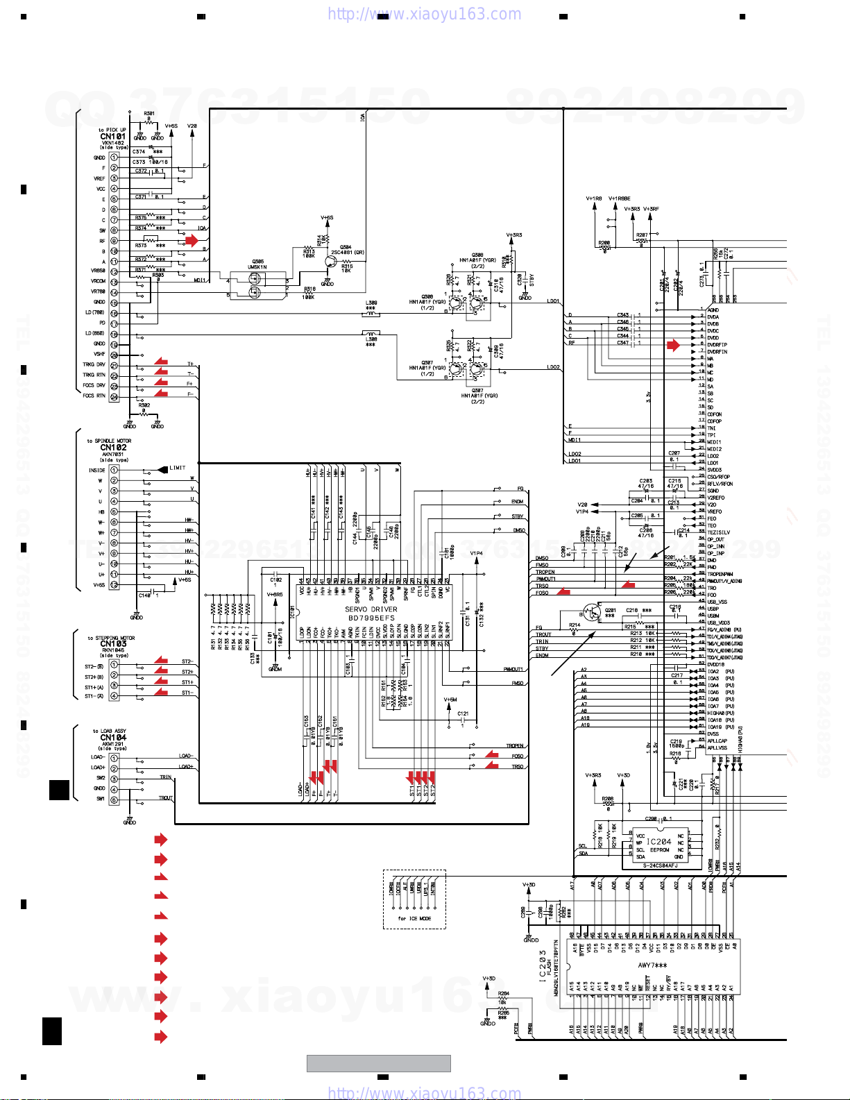
3.3 DVDM ASSY (1/2)
A
7
Q
Q
3
6
3
1
5
1
5
0
8
9
2
4
9
8
2
9
9
(RF)
B
TEL 13942296513 QQ 376315150 892498299
(T)
(T)
(F)
(F)
C
FTS DRIVER
TEL
13942296513
Q
Q
LD Driver for CD
LD Driver for DVD
7
3
6
3
1
5
1
(F)
5
0
2
8
TEL 13942296513 QQ 376315150 892498299
(RF)
3
2
9
(T)
4
9
8
2
9
9
D
E
F
B
18
MOTOR
STEPPING
CN601 PICKUP ASSY CN1013SPINDLE MOTOR
A
w
w
1/2
A
1234
(S)
(S)
(S)
(S)
(RF)
: RF SIGNAL ROUTE
(D)
: AUDIO SIGNAL ROUTE(DIGITAL)
(F)
: FOCUS SERVO LOOP LINE
(T)
: TRACKING SERVO LOOP LINE
(S)
: STEPPING SERVO LOOP LINE
(C/V)
: VIDEO SIGNAL ROUTE
(R/Cr)
: VIDEO SIGNAL ROUTE(R/Cr)
(G/Y)
: VIDEO SIGNAL ROUTE(G/Y)
(B/Cb)
: VIDEO SIGNAL ROUTE(B/Cb)
(S_Y)
w
(S_C)
.
: S VIDEO SIGNAL ROUTE
: S VIDEO SIGNAL ROUTE
xia
(F)
(F)
(T)
(T)
o
y
XV-DV333
u
(S)
(S)
(S)
1
(S)
6
3
1
(F)
(T)
.
c
o
m
5678
7
Q
Q
TEL 13942296513 QQ 376315150 892498299
3
6
3
1
5
(D)
!
1
5
0
(R/CY)
(B/Cb)
(G/Y)
(C/V)
B
8
(S_C)
DVDM ASSY
1/2
(AWM7964)
2
9
(S_Y)
4
9
8
2
9
A
9
B
TEL 13942296513 QQ 376315150 892498299
C
TEL
13942296513
Q
Q
3
7
6
3
1
5
1
5
0
8
9
2
4
9
8
2
9
9
D
E
w
w
w
.
xia
56
o
y
u
1
6
XV-DV333
3
.
c
7
o
m
F
B
1/2
19
8
1234
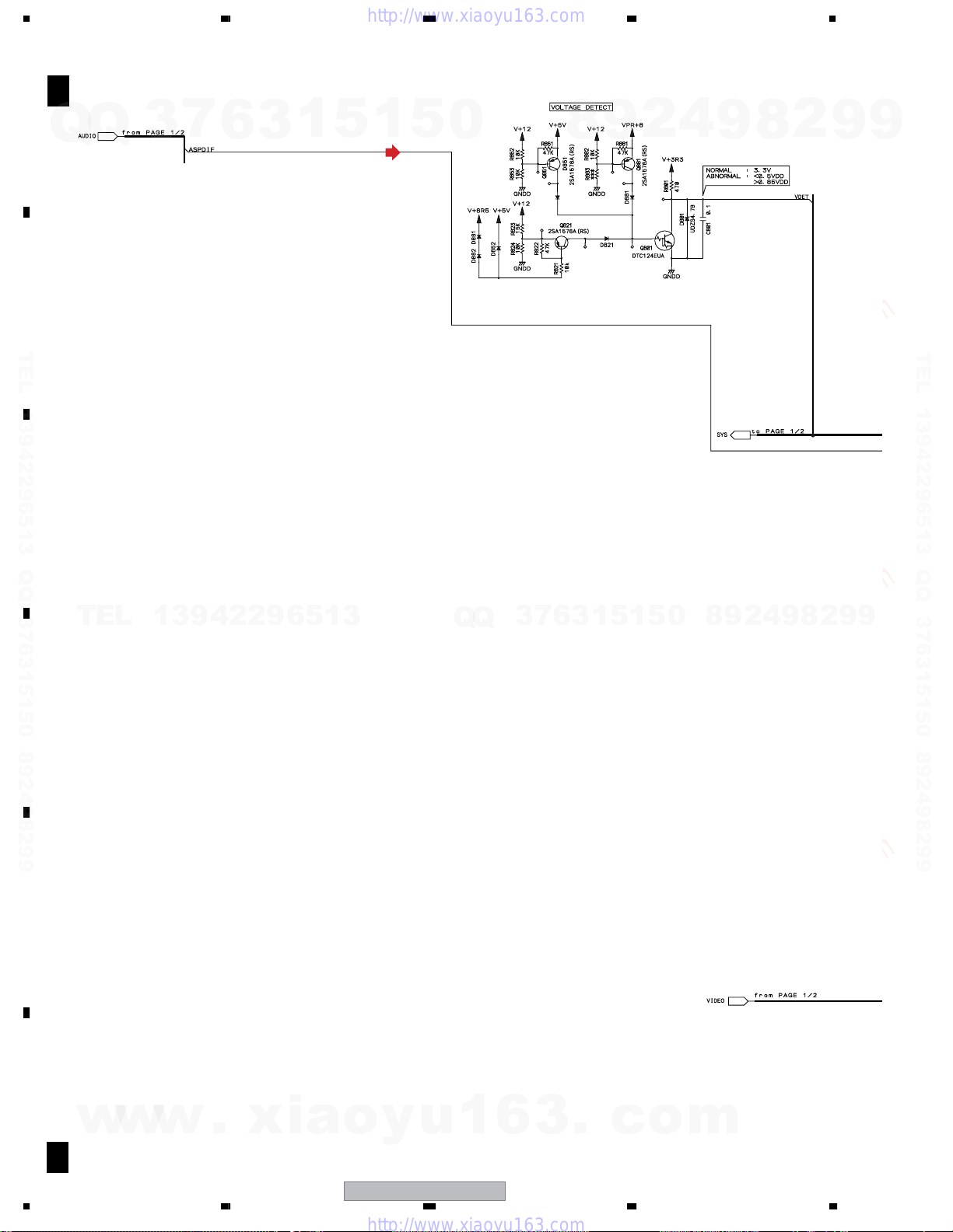
3.4 DVDM ASSY (2/2)
B
A
Q
B
TEL 13942296513 QQ 376315150 892498299
C
DVDM ASSY
2/2
(AWM7964)
Q
3
7
6
3
1
5
1
5
(D)
0
8
9
2
4
9
8
2
9
9
TEL 13942296513 QQ 376315150 892498299
TEL
D
E
13942296513
Q
Q
3
7
6
3
1
5
1
5
0
8
9
2
4
9
8
2
9
9
F
w
w
20
B
A
w
2/2
1234
.
xia
o
y
u
1
6
XV-DV333
3
.
c
o
m
5678
7
Q
Q
TEL 13942296513 QQ 376315150 892498299
3
6
1.8V Regulator
3
1
5
1
5
3V Regulator
5V Regulator
0
7.8V
9
8
6.5V Regulator
2
4
9
(D)
8
2
9
A
9
CN5102
B
TEL 13942296513 QQ 376315150 892498299
TEL
5.0V
13942296513
(S_C)
(C/V)
(C_Y)
(G/Y)
(B/Cb)
(S/Cr)
6.4V
Video Driver Amp
Q
Q
3
7
6
3
1
(S_C)
5
(C/V)
7.8V
1
5
0
(S_Y)
(G/Y)
(B/Cb)
(R/Cr)
8
9
2
4
9
8
2
9
NC
G
B
R
NC
NC
NC
C
9
D
CN8801
I J
w
w
(D)
: AUDIO SIGNAL ROUTE
(C/V)
: VIDEO SIGNAL ROUTE
(R/Cr)
: VIDEO SIGNAL ROUTE(R/Cr)
(G/Y)
: VIDEO SIGNAL ROUTE(G/Y)
(B/Cb)
: VIDEO SIGNAL ROUTE(B/Cb)
(S_Y)
w
(S_C)
.
: S VIDEO SIGNAL ROUTE
: S VIDEO SIGNAL ROUTE
xia
56
(R)
: VIDEO SIGNAL ROUTE(R)
(G)
: VIDEO SIGNAL ROUTE(G)
(B)
: VIDEO SIGNAL ROUTE(B)
o
y
u
1
6
XV-DV333
3
.
c
7
o
m
NC
NC
E
F
B
2/2
A
21
8
1234
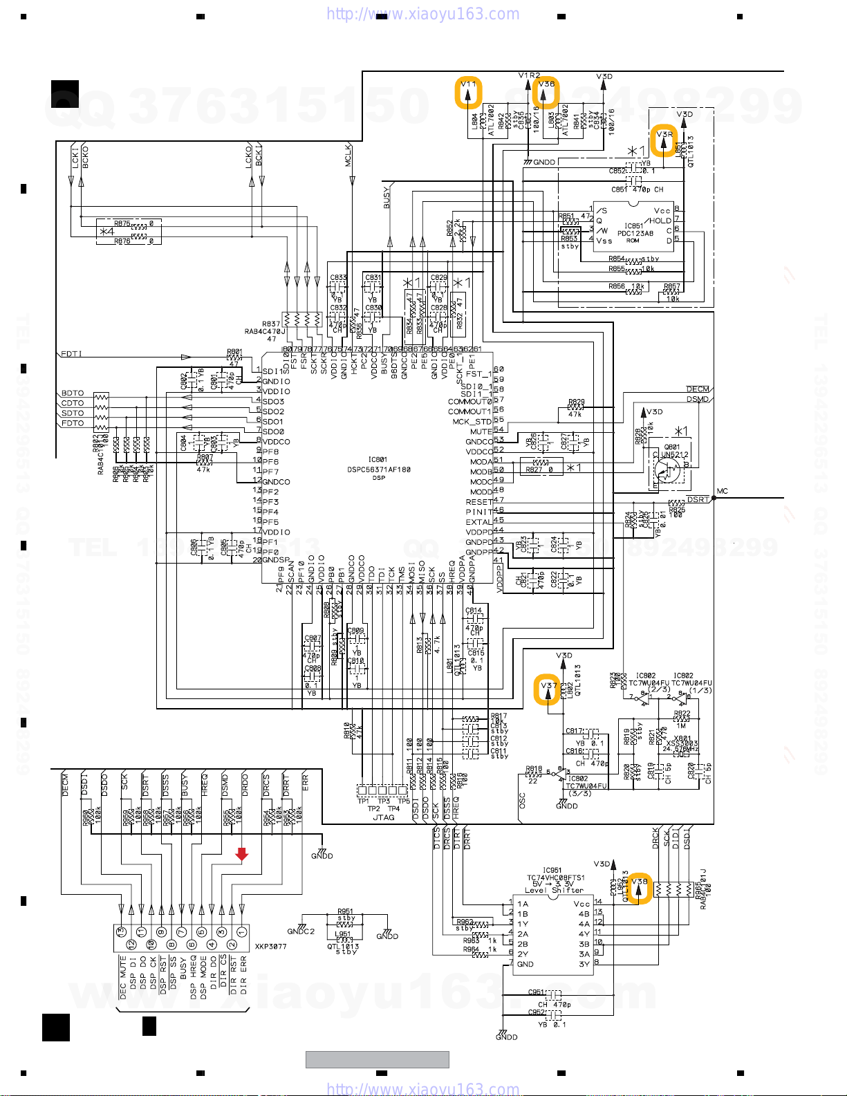
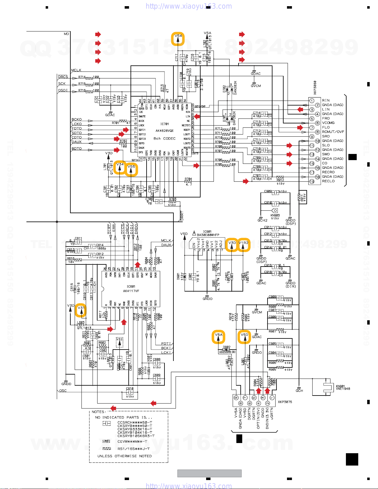
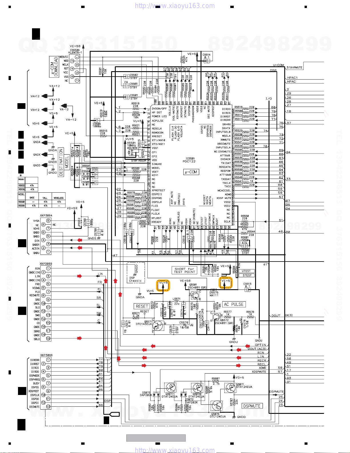
3.5 DSP ASSY
A
B
TEL 13942296513 QQ 376315150 892498299
C
DSP ASSY (AWX8587)
C
7
Q
Q
3
6
3
1
5
1
5
0
8
9
2
4
9
8
2
9
9
TEL 13942296513 QQ 376315150 892498299
TEL
D
E
13942296513
(D)
CN951
Q
Q
3
7
6
3
1
5
1
5
0
8
9
2
4
9
8
2
9
9
F
w
w
22
C
w
F
1234
1/4
.
CN5620
xia
o
y
u
1
6
XV-DV333
3
.
c
o
m
5678
: AUDIO SIGNAL ROUTE(L ch)
(DVD)
: AUDIO SIGNAL ROUTE(DVD L ch)
(D)
7
Q
Q
TEL 13942296513 QQ 376315150 892498299
3
: AUDIO SIGNAL ROUTE(DIGITAL)
1
6
3
(AD)
: AUDIO DATA SIGNAL ROUTE
(AD)
(AD)
(AD)
5
(AD)
1
5
0
(DVD)
(SL)
8
(SW)
(DVD)
(FL)
: AUDIO SIGNAL ROUTE(Front L ch)
: AUDIO SIGNAL ROUTE(Surround L ch)
(C)
: AUDIO SIGNAL ROUTE(Center ch)
9
: AUDIO SIGNAL ROUTE(Sub Woofer ch)
2
4
9
(FL)
(SL)
(sw)
(C)
8
2
CN701
9
9
A
B
TEL 13942296513 QQ 376315150 892498299
CN5612
1/4
F
C
TEL
13942296513
(D)
(D)
(D)
(D)
(D)
Q
Q
3
7
6
3
1
5
1
5
(D)
0
8
(D)
CN901
9
2
4
9
8
2
9
9
D
E
w
w
w
.
xia
56
o
y
u
1
6
XV-DV333
3
.
F
c
1/4
7
CN5613
o
F
m
C
23
8
1234
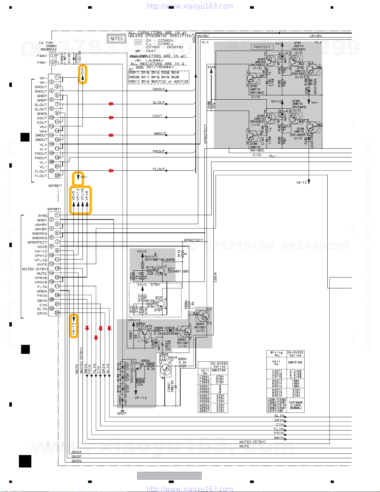
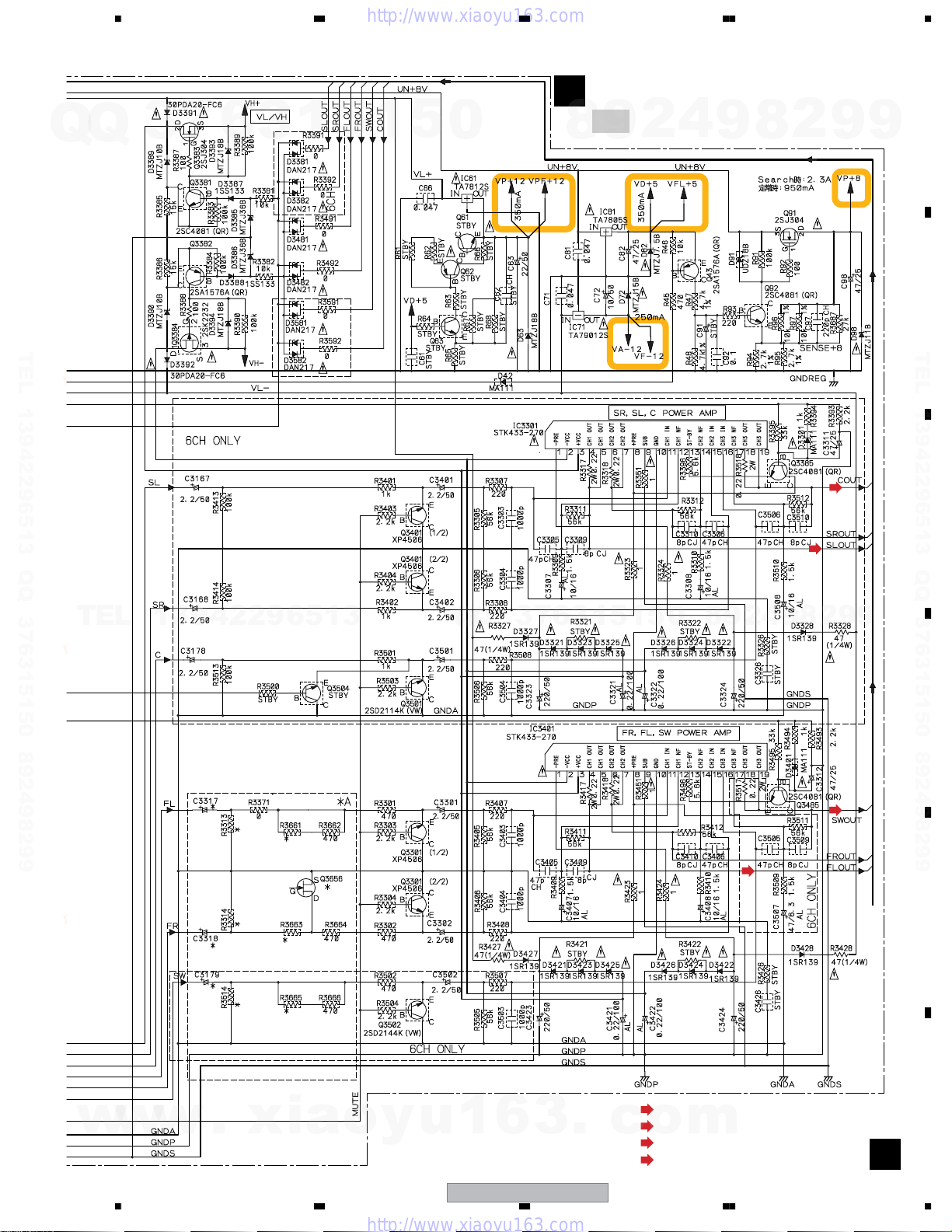
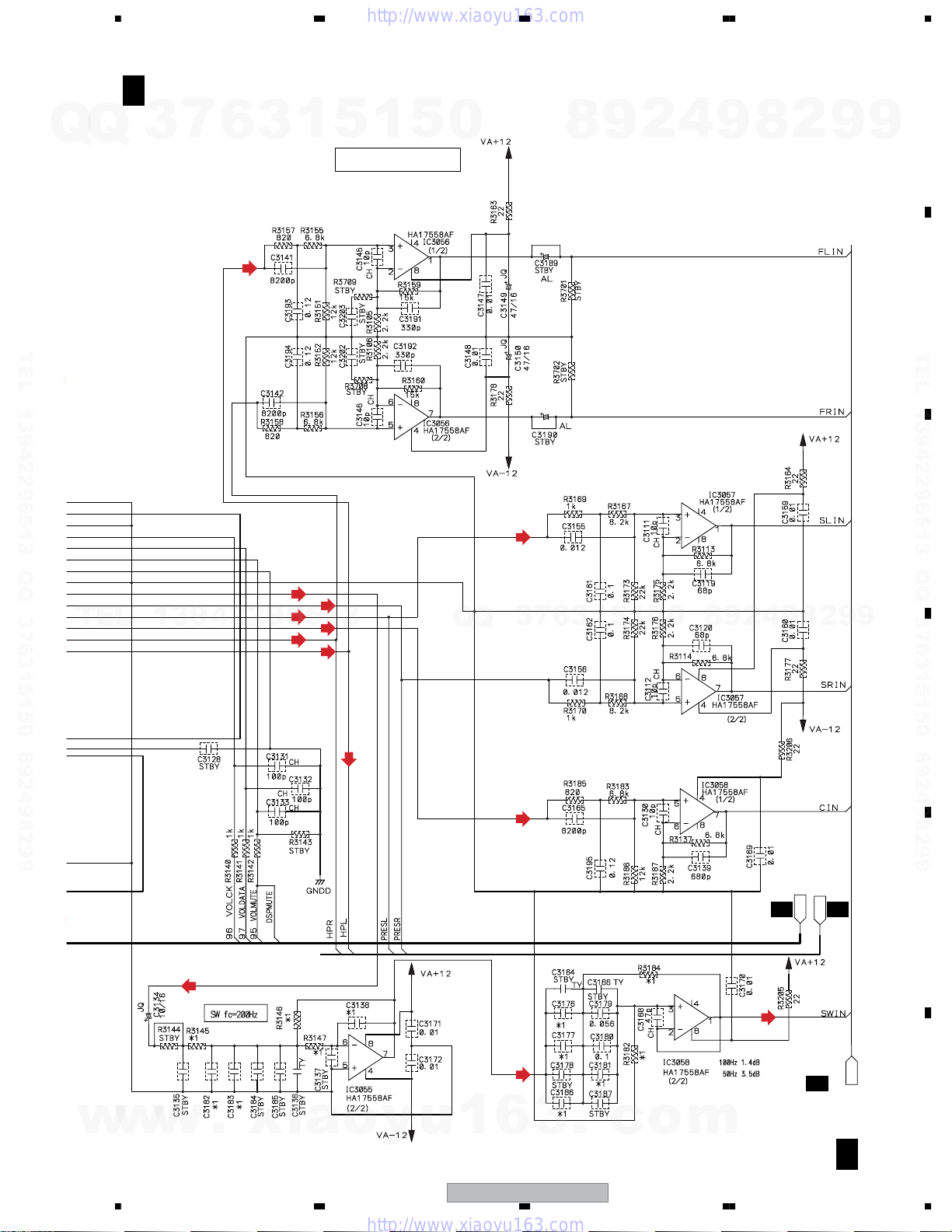
3.6 6CH AMP ASSY
A
7
Q
Q
B
CN3011
TEL 13942296513 QQ 376315150 892498299
G
3
6
3
1
(SL)
(C)
(SW)
(FL)
5
1
5
0
8
2
9
2
4
9
8
2
9
9
TEL 13942296513 QQ 376315150 892498299
CN3001
C
D
CN3002
TEL
CN3012
G
13942296513
(FL)
(SL)
(C)
(SW)
5
3
Q
Q
3
7
6
3
1
5
1
5
0
8
9
2
4
9
8
2
9
9
E
F
w
w
w
D
24
1234
.
xia
o
y
u
1
6
XV-DV333
3
.
c
o
m
Q
Q
3
5678
7
6
3
1
5
1
5
0
6CH AMP (XWK3188)
D
: Refer to "7.3.2 PROTECTION CIRCUIT.
4
2
9
8
9
8
2
9
A
9
B
TEL 13942296513 QQ 376315150 892498299
TEL
13942296513
Q
Q
3
7
6
3
1
5
1
5
0
8
9
2
4
9
(SL)
8
(C)
2
9
TEL 13942296513 QQ 376315150 892498299
C
9
D
w
w
w
.
xia
56
o
y
u
1
6
XV-DV333
3
.
(FL)
(FL)
: AUDIO SIGNAL ROUTE (Front L ch)
(SL)
: AUDIO SIGNAL ROUTE (Surround L ch)
c
o
(C)
(SW)
7
m
: AUDIO SIGNAL ROUTE (Center ch)
: AUDIO SIGNAL ROUTE (Sub Woofer ch)
(SW)
E
F
D
25
8
1234
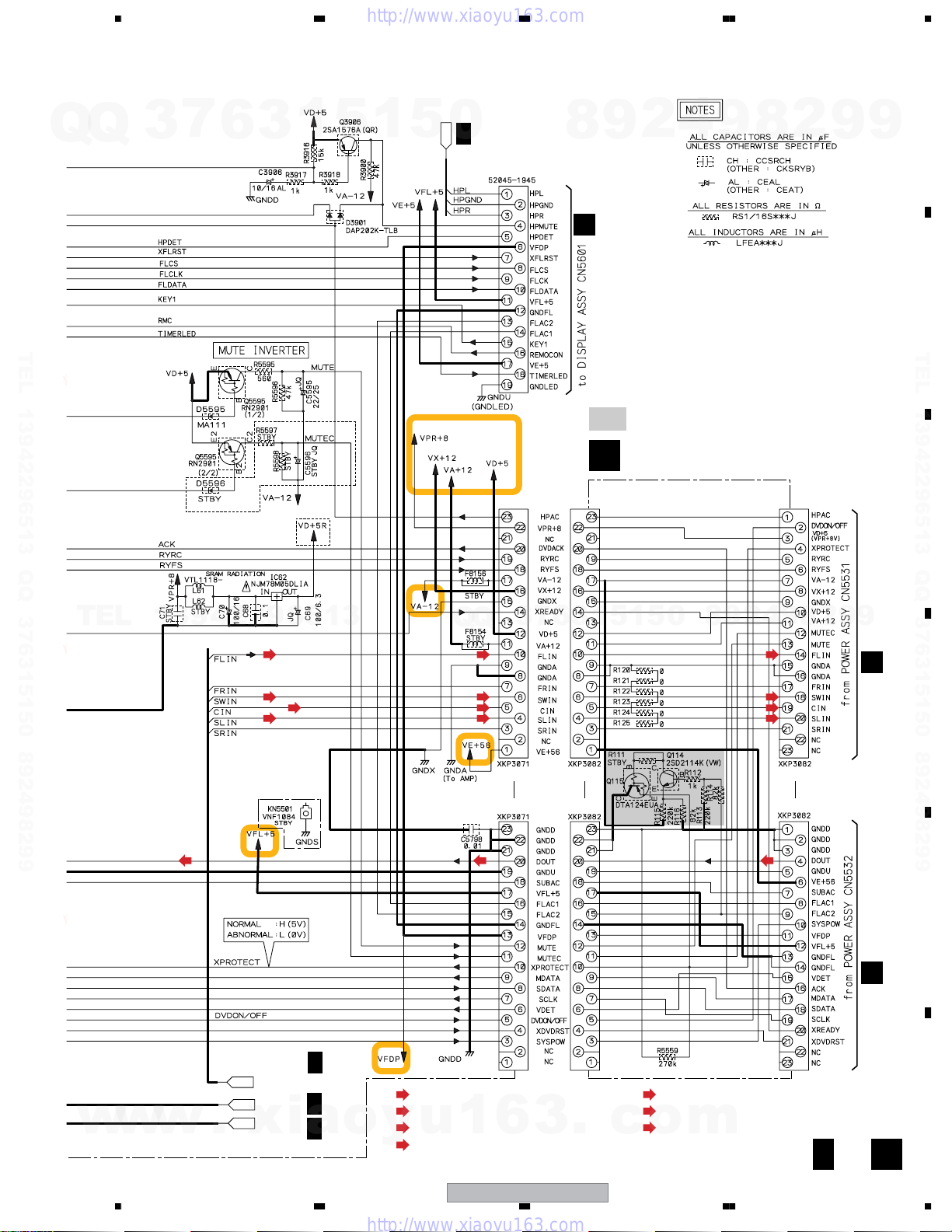
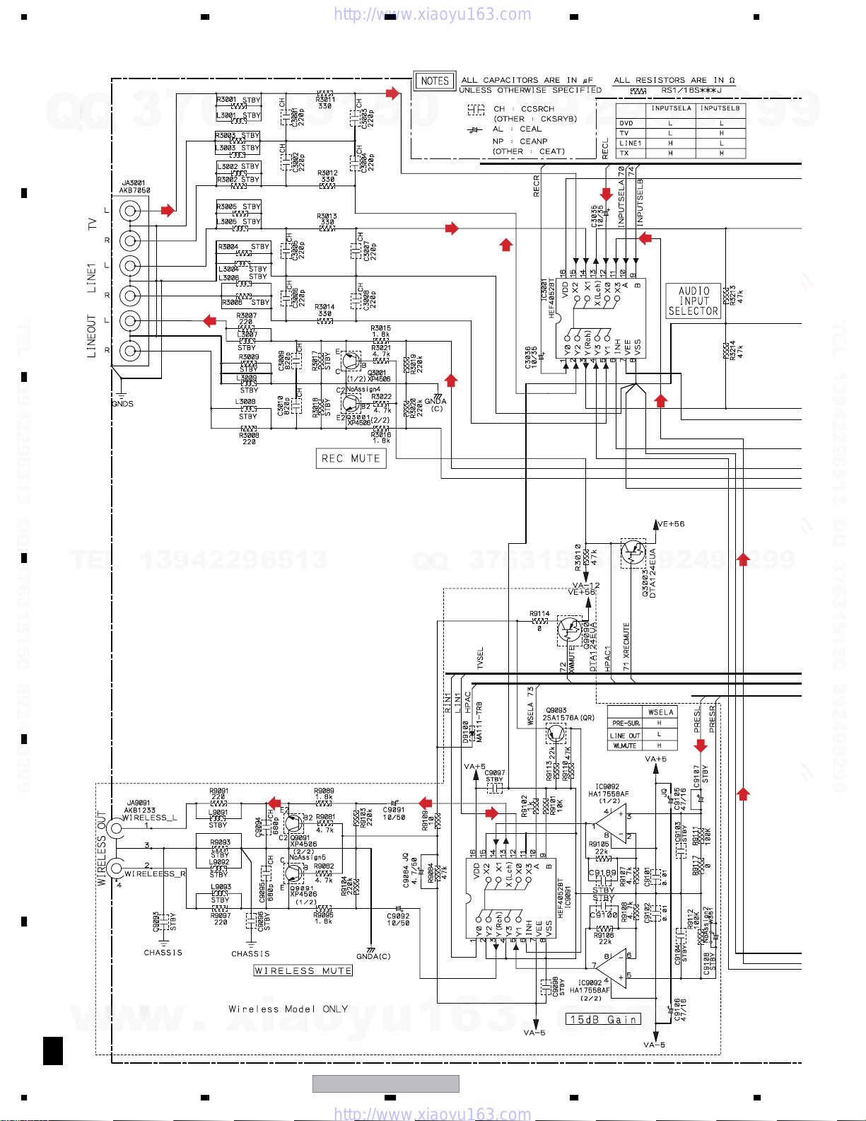
3.7 CONTROL (1/4) and TRADE 2 ASSYS
A
F
Q
Q
2/4-4/4
F
B
TEL 13942296513 QQ 376315150 892498299
F
4/4
F
2/4-4/4
F
4/3
F
2/4-4/4
XV-DV535
XV-DV333
C
XV-DV333
CONTROL ASSY (XWZ3969 : XV-DV333)(XWZ3984 : XV-DV434)
1/4
(XWZ3989 : XV-DV535)
XV-DV434
3
XV-DV535
7
6
3
1
5
1
5
0
8
9
2
4
9
8
2
9
9
TEL 13942296513 QQ 376315150 892498299
CN5613
TEL
CN901
CCC
D
E
CN5612
CN701CN951
CN5620
13942296513
(D)
(D)
(D)
(D)
(DVD)
(DVD)
(DVD)
(D)
(D)
Q
Q
3
7
6
3
1
5
1
(DVD)
5
(D)
0
(D)
8
9
2
4
9
8
2
9
9
F
w
w
26
F
A
w
1/4
1234
.
DSPAOUT
xia
F
2/4
o
y
u
1
6
XV-DV333
3
.
c
o
m
Q
Q
3
5678
7
6
3
1
5
1
5
0
F
4/4
HPINPUT
CN5611
8
H
2
9
CN5601
4
9
8
2
9
A
9
B
TEL 13942296513 QQ 376315150 892498299
TEL
13942296513
(FL)
(SW)
(C)
(SL)
Q
(FL)
(SW)
(SL)
Q
(C)
3
CN5501
7
3
6
CN5511
: Refer to "7.3.2 PROTECTION CIRCUIT.
TRADE 2 ASSY (XWZ3998)
E
4
2
9
8
0
5
1
5
1
(FL)
(SW)
(C)
(SL)
CN5521
9
8
2
9
TEL 13942296513 QQ 376315150 892498299
C
9
CN5531CN5532
JJ
D
w
w
w
CN5502
(D)
F
2/4
EVOLAOUT
U-COM
I/O
.
xia
56
F
3/4,4/4
F
3/4,4/4
o
: AUDIO SIGNAL ROUTE (L ch)
(DVD)
: AUDIO SIGNAL ROUTE (DVD L ch)
(D)
: AUDIO SIGNAL ROUTE (DIGITAL)
y
u
(FL)
: AUDIO SIGNAL ROUTE (Front L ch)
1
(D)
6
XV-DV333
CN5512
3
.
(SL)
(C)
(SW)
c
7
CN5522
(D)
: AUDIO SIGNAL ROUTE (Surround L ch)
: AUDIO SIGNAL ROUTE (Center ch)
: AUDIO SIGNAL ROUTE (Sub Woofer ch)
o
m
F
8
1/4
E
F
E
27
1234
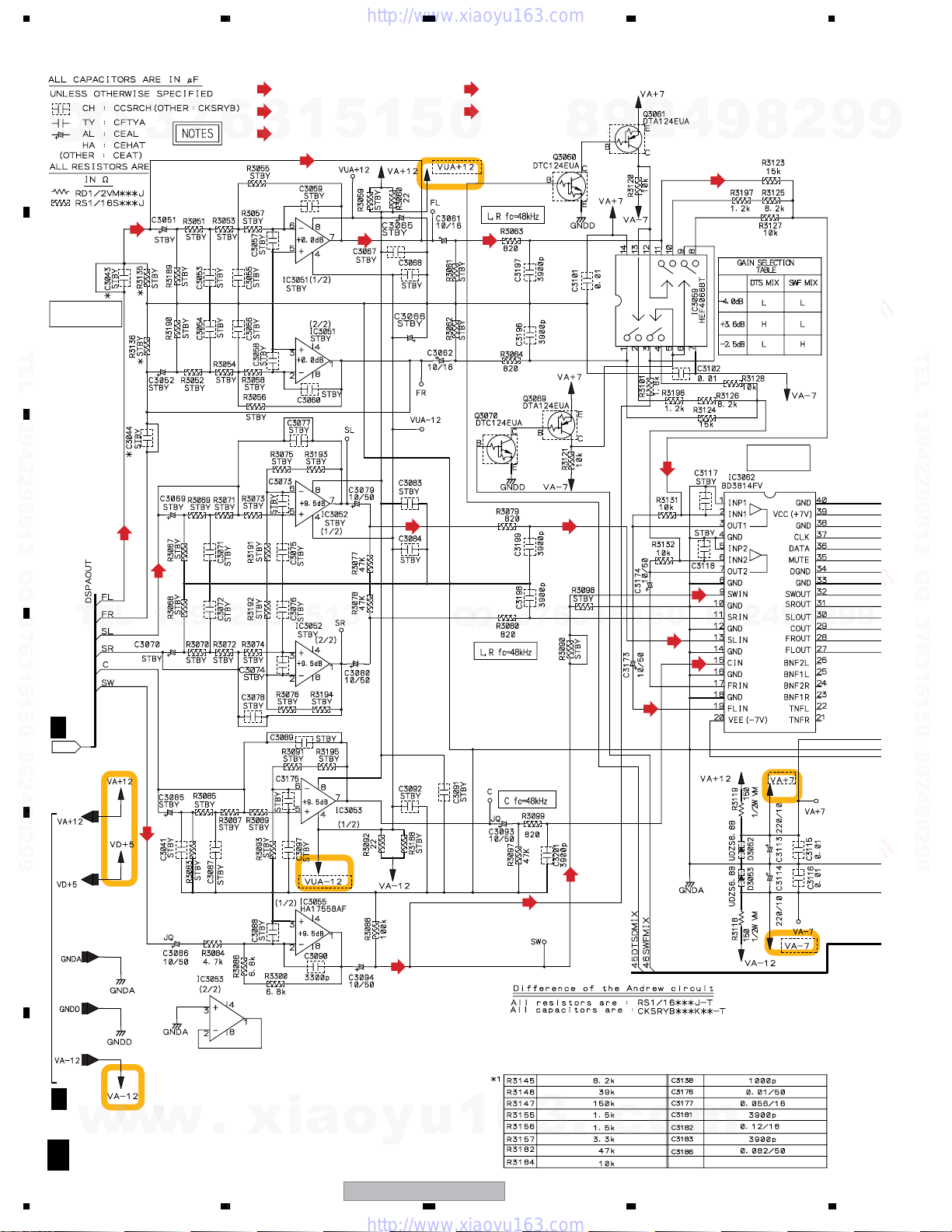
3.8 CONTROL (2/4) ASSY
(SL)
6
(SW)
(SW)
A
Q
Q
3
7
: SLch AUDIO SIGNAL ROUTE
: SWch AUDIO SIGNAL ROUTE
: SWch AUDIO SIGNAL ROUTE(THEATER BASS)
1
5
3
1
5
(FL)
0
: AUDIO SIGNAL ROUTE
: FLch AUDIO SIGNAL ROUTE
9
8
2
4
9
8
2
9
9
(FL)
(FL)
B
LPF & GAIN
TEL 13942296513 QQ 376315150 892498299
C
(FL)
(SL)
(FL) (FL)
(SL) (SL)
(SW)
(FL)
(FL)
TEL 13942296513 QQ 376315150 892498299
E-VOL
D
F
DSPAOUT
E
TEL
1/4
13942296513
(SW)
(SW)
Q
Q
3
(SW)
7
6
3
1
(SW)
5
1
(FL)
5
(SL)
0
(C)
8
9
2
4
9
8
2
9
9
F
F
1/4,2/4-4/4
w
F 2/4
28
w
w
1234
.
xia
o
y
u
1
6
XV-DV333
3
.
c
o
m
5678
F 2/4
Q
TEL 13942296513 QQ 376315150 892498299
(XWZ3969 : XV-DV333)
Q
(XWZ3984 : XV-DV434)
(XWZ3989 : XV-DV535)
CONTROL ASSY
7
3
6
(FL)
3
1
5
ANDREW CIRCUIT
1
5
0
(SL)
8
9
2
4
9
8
2
9
A
9
B
TEL 13942296513 QQ 376315150 892498299
C
TEL
(SW)
(SR)
13942296513
(SW)
(SL)
(FR)
(C)
(FL)
(FL)
Q
Q
(C)
3
7
6
3
1
5
1
5
0
8
9
2
(SW)
2
8
9
4
U-COM
ANALOGOUT
F 1/4, 3/4, 4/4
9
9
F 3/4,4/4
D
E
w
w
w
(SW)
.
xia
56
o
y
u
1
6
XV-DV333
3
.
c
7
o
m
F 1/4
F
EVOLAOUT
F 2/4
29
8
1234
3.9 CONTROL (3/4) ASSY
A
7
Q
Q
B
TEL 13942296513 QQ 376315150 892498299
C
3
(TVL)
6
(FL)
3
1
5
1
(PRETVL)
5
0
(LINE1L)
(LOUT)
8
(TVL)
9
2
4
9
(TXL)
(TXL)
8
2
9
9
TEL 13942296513 QQ 376315150 892498299
TEL
D
E
13942296513
(WIRELESS_L)
Q
Q
3
7
6
3
1
5
1
5
0
8
9
2
9
4
(PRESL)
8
2
9
(TXL) (TXL)
9
F
30
w
F 3/4
XV-DV535
w
w
1234
.
xia
o
y
u
1
6
XV-DV333
3
.
c
o
m
 Loading...