

Page 1
> Before Start > Part Names > Install > Initial Setup > Playback > Advanced Manual
Troubleshooting | Supplementary Information, etc.
Basic
Manual
VSX-LX302
AV RECEIVER
Before Start ............................................................................2
What's in the box......................................................................2
Part Names .............................................................................3
Part Names ..............................................................................3
Install ......................................................................................7
Installation procedure ...............................................................7
Step1: Speaker Layout .............................................................8
Step2: Connect the Speakers.................................................15
Step3: Connect the TV & AV Components.............................17
Initial Setup ..........................................................................23
Initial Setup with Auto Start-up Wizard ...................................23
Playback ...............................................................................25
AV Component Playback........................................................25
BLUETOOTH
Network Functions..................................................................26
USB Storage Device...............................................................27
Listening To the AM/FM Radio...............................................28
Multi-zone...............................................................................30
Listening Mode.......................................................................31
The Basic Manual includes information needed when starting up and
also instructions for frequently used operations. The Advanced Manual
has more detailed information and advanced settings.
®
Playback........................................................25
Page 2
Before Start
> Before Start > Part Names > Install > Initial Setup > Playback > Advanced Manual
Troubleshooting | Supplementary Information, etc.
1
32
54
6
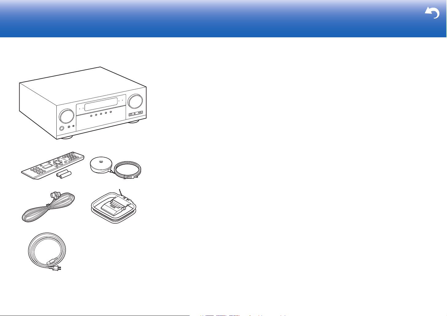
What's in the box
1. Main unit (1)
2. Remote controller (RC-957R) (1), Batteries (AAA/R03)
(2)
3. Speaker setup microphone (1)
0 Used during Initial Setup.
4. Indoor FM antenna (1)
5. AM loop antenna (1)
6. Power cord (1)
0 Quick Start Guide (1)
0 Basic Manual (This manual)
0 Connect speakers with 4 Ω to 16 Ω impedance.
0 The power cord must be connected only after all other
cable connections are completed.
0 We will not accept responsibility for damage arising from
the connection of equipment manufactured by other
companies.
0 Functionality may be introduced by firmware updates
and service providers may cease services, meaning that
some network services and content may become
unavailable in the future. Furthermore, available services
may vary depending on your area of residence.
0 Details on the firmware update will be posted on our
website and through other means at a later date.
0 Specifications and appearance are subject to change
without prior notice.
2
Page 3
Part Names
> Before Start > Part Names >Install >Initial Setup >Playback > Advanced Manual
Troubleshooting | Supplementary Information, etc.
En
Part Names
(*)You can find details in the Advanced Manual.
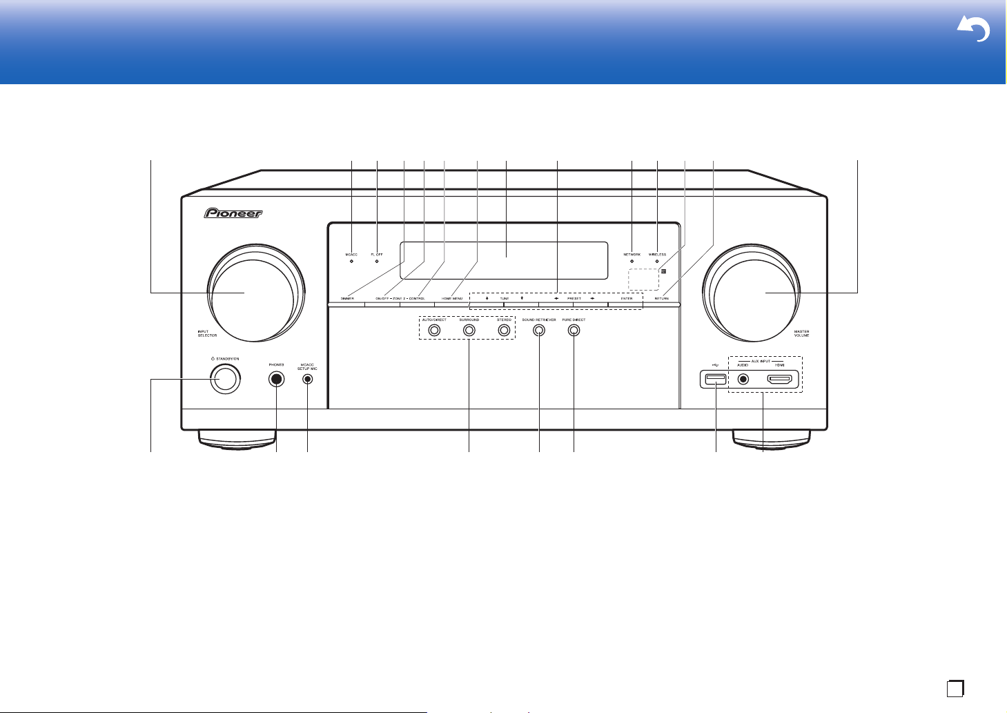
Front Panel
1. INPUT SELECTOR dial: Switch the input to be played.
2. MCACC indicator: This lights when you have enabled the speaker calibration made with
MCACC (P23).
3. FL OFF indicator: This lights when you have pressed DIMMER repeatedly to turn the
display off.
4. DIMMER button: You can switch the display off or adjust the brightness of the display in
three steps.
5. ZONE 2-ON/OFF button: Switches the multi-zone function on/off (P30).
6. ZONE 2-CONTROL button: Controls the multi-zone function (P30).
7. HOME MENU button: Displays the Home. (*)
8. Display (P4)
9. Cursor buttons ( / / / ) and ENTER button: Select the item with the cursors and
press ENTER to confirm. Use them to tune to stations when using TUNER (P28).
10.
NETWORK indicator: This lights when "NET" is selected with the input selector and the
unit is connected to the network. If the unit is in standby mode, this lights when functions
such as HDMI CEC and network standby are enabled. It does not light when ZONE 2 is
on, however.
11.
WIRELESS indicator: Lights when the unit is connected to the wireless network and when
connected to a BLUETOOTH enabled device.
12.
Remote control sensor: Receives signals from the remote controller.
0 The signal range of the remote controller is within about 16´/5 m, at an angle of 20° on
the perpendicular axis and 30° to either side.
13.
RETURN button: Returns the display to the previous state.
14.
MASTER VOLUME
15.
Í STANDBY/ON button
16.
PHONES jack: Headphones with a standard plug (Ø1/4"/6.3 mm) are connected.
3
Page 4
> Before Start > Part Names >Install >Initial Setup >Playback > Advanced Manual
Troubleshooting | Supplementary Information, etc.
(*)You can find details in the Advanced Manual.
17.
MCACC SETUP MIC jack: The supplied speaker setup
microphone is connected.
18.
Listening mode button: Press "AUTO/DIRECT",
"SURROUND" or "STEREO" to switch the listening
mode (P31). (*)
19.
SOUND RETRIEVER button: Turns on/off the Sound
Retriever function that provides better sound quality for
compressed audio.
20.
PURE DIRECT button: Switches to the Pure Direct
mode (P31).
21.
USB port: A USB storage device is connected so that
music files stored in it can be played. You can also
supply power (5 V/500 mA) to USB devices with a USB
cable.
22.
AUX INPUT AUDIO/HDMI jack: Connect a video
camera, etc., using a stereo mini plug cable (Ø1/8"/
3.5 mm) or a HDMI cable.
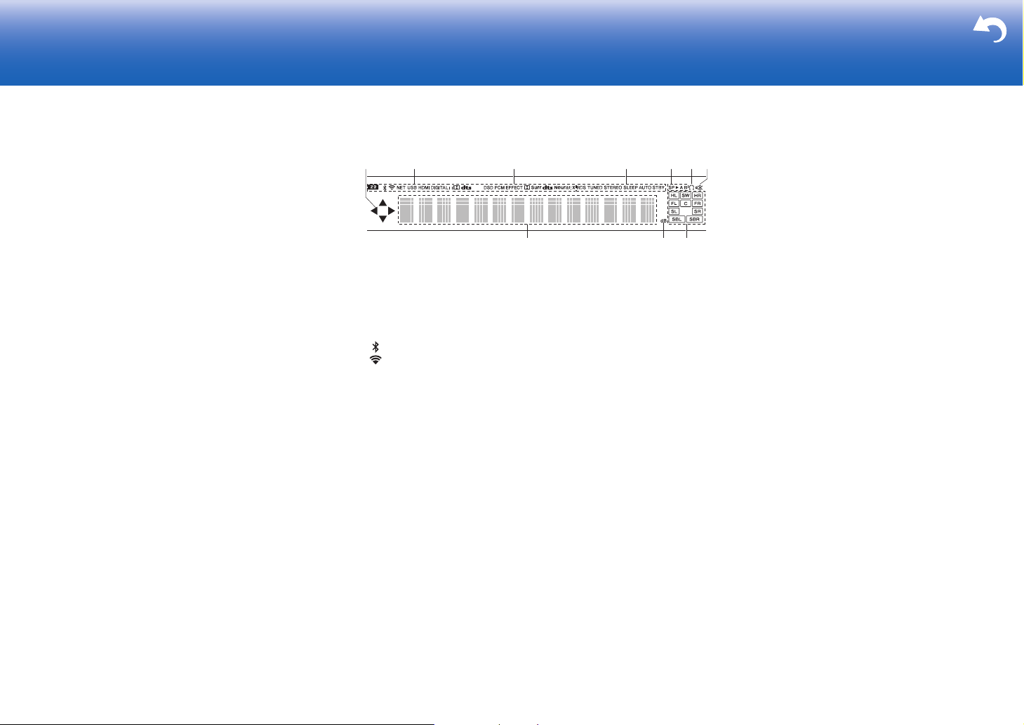
Display
1. This may light when performing operations with the "NET", "USB" input
selector.
2. Lights in the following conditions.
Z2: When ZONE 2 is on.
: When connected by BLUETOOTH.
: When connected by Wi-Fi.
NET: When "NET" is selected with the input selector and the unit is
connected to the network. It will flash if the connection to the network is
not correct.
USB: When "USB" is selected with the input selector and the unit is
connected by USB and the USB device is selected. Flashes if the USB
is not properly connected.
HDMI: When HDMI signals are input and the HDMI input is selected.
DIGITAL: When digital signals are input and the digital input is
selected.
3. Lights according to the type of input digital audio signals and the
listening mode.
4. Lights in the following conditions.
RDS: Receiving RDS broadcasting.
TUNED: Receiving AM/FM radio.
STEREO: Receiving FM stereo.
SLEEP: When the sleep timer is set.
AUTO STBY: Auto Standby is on.
5. The currently selected speaker system lights.
6. Lights when headphones are connected.
7. Flashes when muting is on.
8. Displays various information of the input signals.
9. Lights when adjusting the volume.
10.
Speaker/Channel display: Displays the output channel that
corresponds to the selected listening mode.
4
Page 5
> Before Start > Part Names >Install >Initial Setup >Playback > Advanced Manual
Troubleshooting | Supplementary Information, etc.
180°
90°
En
(*)You can find details in the Advanced Manual.
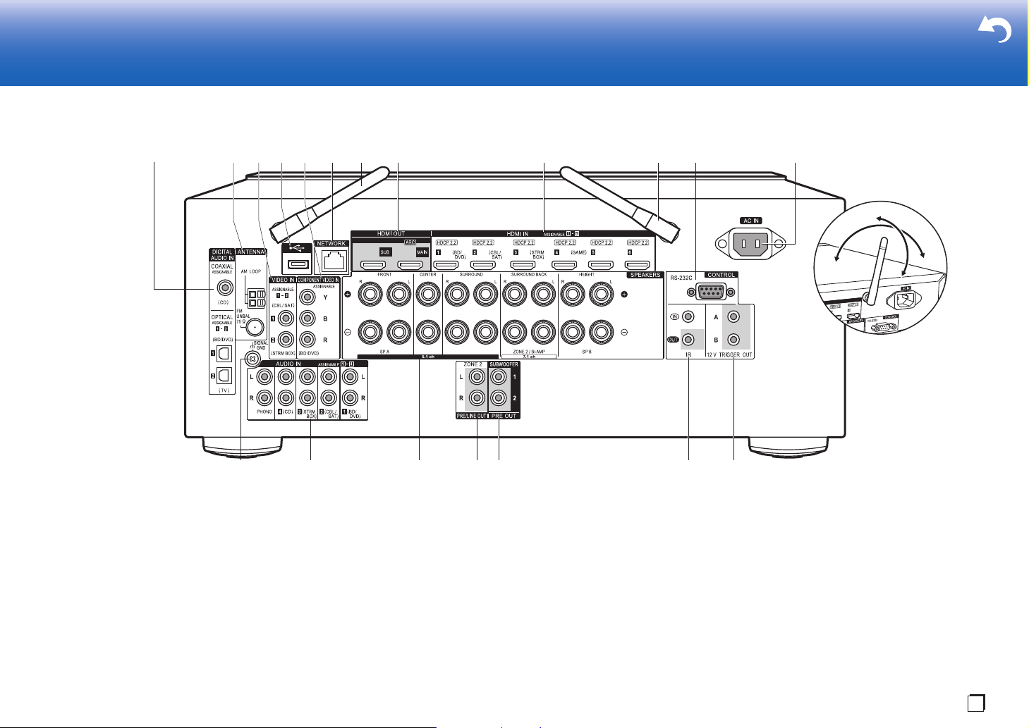
Rear Panel
1. DIGITAL AUDIO IN OPTICAL/COAXIAL jacks: Input TV or AV component digital audio
signals with a digital optical cable or digital coaxial cable.
2. ANTENNA AM LOOP/FM UNBAL 75Ω terminal: The supplied antennas are connected.
3. VIDEO IN jacks: Input the AV component video signals with an analog video cable.
4. USB port: A USB storage device is connected so that music files stored in it can be
played. You can also supply power (5 V/500 mA) to USB devices with a USB cable.
5. COMPONENT VIDEO IN jacks: Input the AV component video signals with a component
video cable. (Compatible only with 480i or 576i resolution.)
6. NETWORK port: Connect to the network with an Ethernet cable.
7. Wireless antenna: Used for Wi-Fi connection or when using a BLUETOOTH enabled
8. HDMI OUT jacks: Transmit video signals and audio signals with a HDMI cable connected
device. Adjust their angles according to the connection status.
to a monitor such as a TV or projector.
9. HDMI IN jacks: Transmit video signals and audio signals with a HDMI cable connected to
an AV component.
10.
RS-232C port: For connection to the home control system. (*)
11.
AC IN: The supplied power cord is connected.
12.
SIGNAL GND terminal: The ground wire of the turntable is connected.
13.
AUDIO IN jacks: Input AV component audio signal with an analog audio cable.
14.
SPEAKERS terminals: Connect speakers with speaker cables.
15.
ZONE 2 PRE/LINE OUT jacks: Output audio signals with an analog audio cable to a premain amplifier or a power amplifier in a separate room (ZONE 2).
16.
SUBWOOFER PRE OUT jack: Connect a powered subwoofer with a subwoofer cable.
Up to two powered subwoofers can be connected. The same signal is output from each of
the SUBWOOFER PRE OUT jacks.
5
Page 6
> Before Start > Part Names >Install >Initial Setup >Playback > Advanced Manual
Troubleshooting | Supplementary Information, etc.
Tips
When the remote controller isn't working: The
remote controller may have switched to the mode
for controlling ZONE 2. While holding down
MODE, press MAIN for 3 seconds or more until
the remote indicator flashes once to switch it to
the mode to control the main room.
17.
IR IN/OUT port: Allows you to connect a multiroom
remote control kit. (*)
18.
12V TRIGGER OUT A/B jack: Allows you to connect a
device with 12V trigger input jack to enable link
operation between the device and the unit. (*)
(*)You can find details in the Advanced Manual.
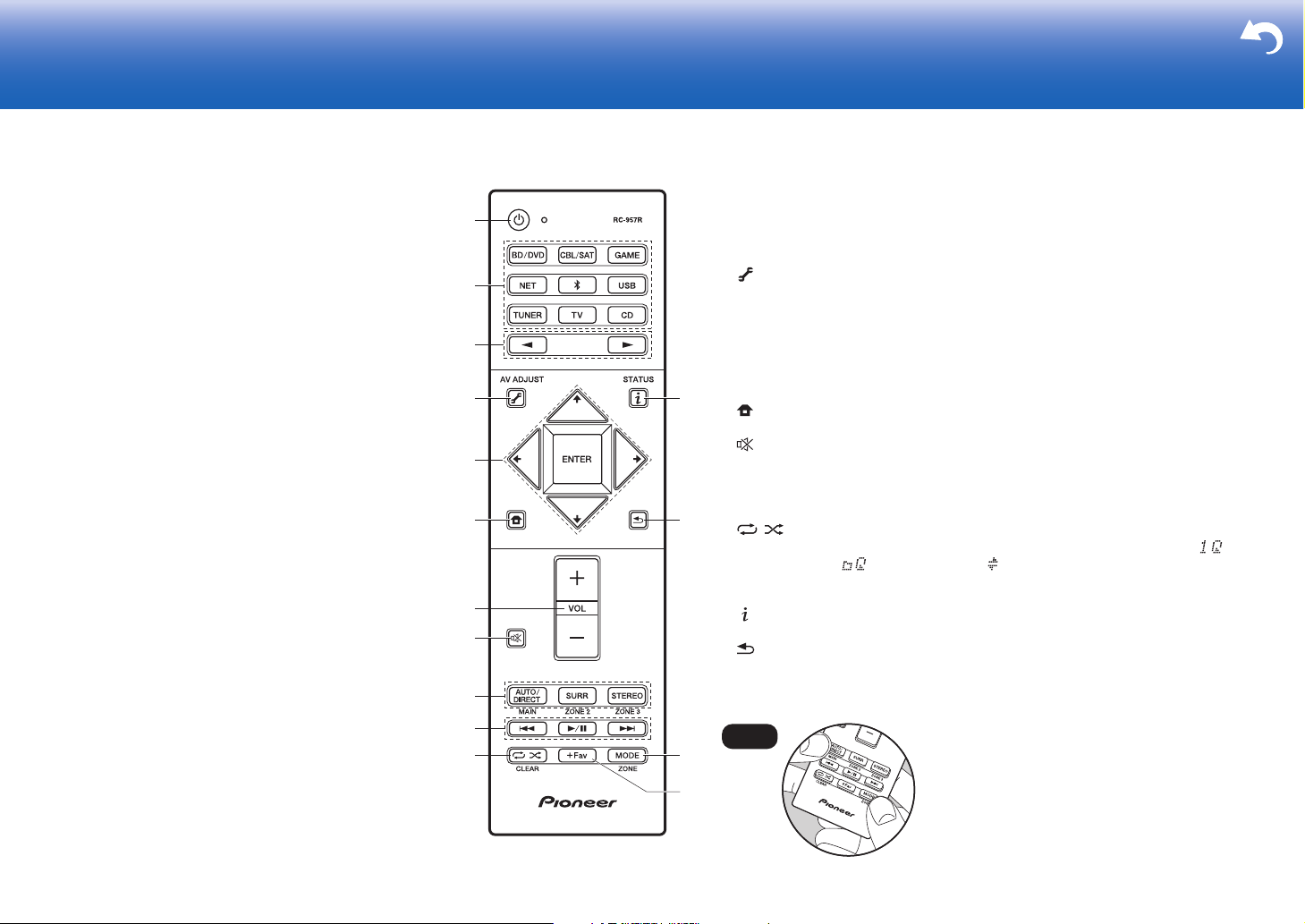
Remote Controller
1. Í STANDBY/ON button
2. Input selector buttons: Switches the input to be played.
3. 21 buttons: Select the input to be played.
4. (AV ADJUST) button: Settings such as "Tone" and "Level" can be made quickly
during play on the TV screen. "Other" has settings to switch the speakers given
priority for output (P15) and to switch HDMI output (P17). Note that there is no display
on the TV screen when the input selector is "CD", "TV", "PHONO", "AM", or "FM", so
follow the display on the main unit while doing the operations. (*)
5. Cursor buttons and ENTER button: Select the item with the cursors and press
ENTER to confirm your selection. When the folder or file lists are not shown on
one screen on the TV, press / to change the screen.
6. button: Displays the Home. (*)
7. Volume buttons
8. button: Temporarily mutes audio. Press again to cancel muting.
9. LISTENING MODE buttons: Allows you to select the listening mode (P31). (*)
MAIN/ZONE 2 buttons: Controls the multi-zone function (P30). (The ZONE 3
button is not used with this unit.)
10.
Play buttons: Used for play operations when playing Music Server or USB.
11.
12.
13.
14.
15.
button: Used for repeat or random play operations when playing Music
Server or USB. Each time you press the button, the mode switches from (1track repeat), to (folder repeat), to (random).
CLEAR button: Deletes all characters you have entered when entering text on
the TV screen.
button: Switches the information on the display and is used to operate RDS
(P29).
button: Returns the display to the previous state.
MODE button: Switches tuning to an AM/FM station between automatic tuning
and manual tuning (P28), and also used to control the multi-zone feature (P30).
+Fav button: Used to register AM/FM radio stations.
6
Page 7
Install
> Before Start > Part Names >Install > Initial Setup > Playback > Advanced Manual
Troubleshooting | Supplementary Information, etc.
1
2 3
En
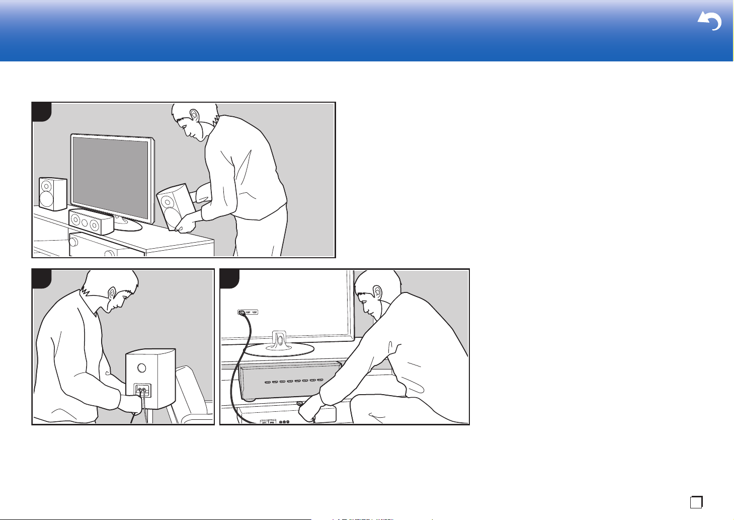
Installation procedure
This unit can be used in a number of ways, depending on
the layout of the speakers you are installing, and the
connections made to external devices. Read the following
to help make the installation process smoother.
Step1: Speaker Layout
Select the speaker layout that suits the types of speakers
you have and the conditions they will be used in from the
choices presented on pages P8 to P13, then install the
speakers by referring to the illustrations and explanations
on the relevant page. Speaker layouts include systems that
use surround back speakers, systems that use height
speakers, and systems that use Bi-Amping speakers. Also
refer to the combinations available in "Speaker
combinations" on P14.
Step2: Connect the Speakers
To connect the speaker systems to this unit, refer to P15 if
you are using a speaker layout described on one of P8 to
P12, and to P16 to use a speaker layout using Bi-Amping
speakers described on P13. The connection process will be
smoother if you refer to the illustrations and explanations
and prepare the required cables before hand.
Step3: Connect the TV & AV Components
Refer to P17 to P22 to connect your external devices such
as your TV, Blu-ray Disc Player, and also supplied
accessories such as the antennas. Also, P21 introduces
the Multi-zone Connection option that allows you to play
audio into rooms other than the main room. The connection
process will be smoother if you refer to the illustrations and
explanations, confirm the connection types on the external
devices, and prepare the required cables before hand.
7
Page 8
Step1: Speaker Layout
> Before Start > Part Names >Install > Initial Setup > Playback > Advanced Manual
Troubleshooting | Supplementary Information, etc.
*
1
*
2
*
3
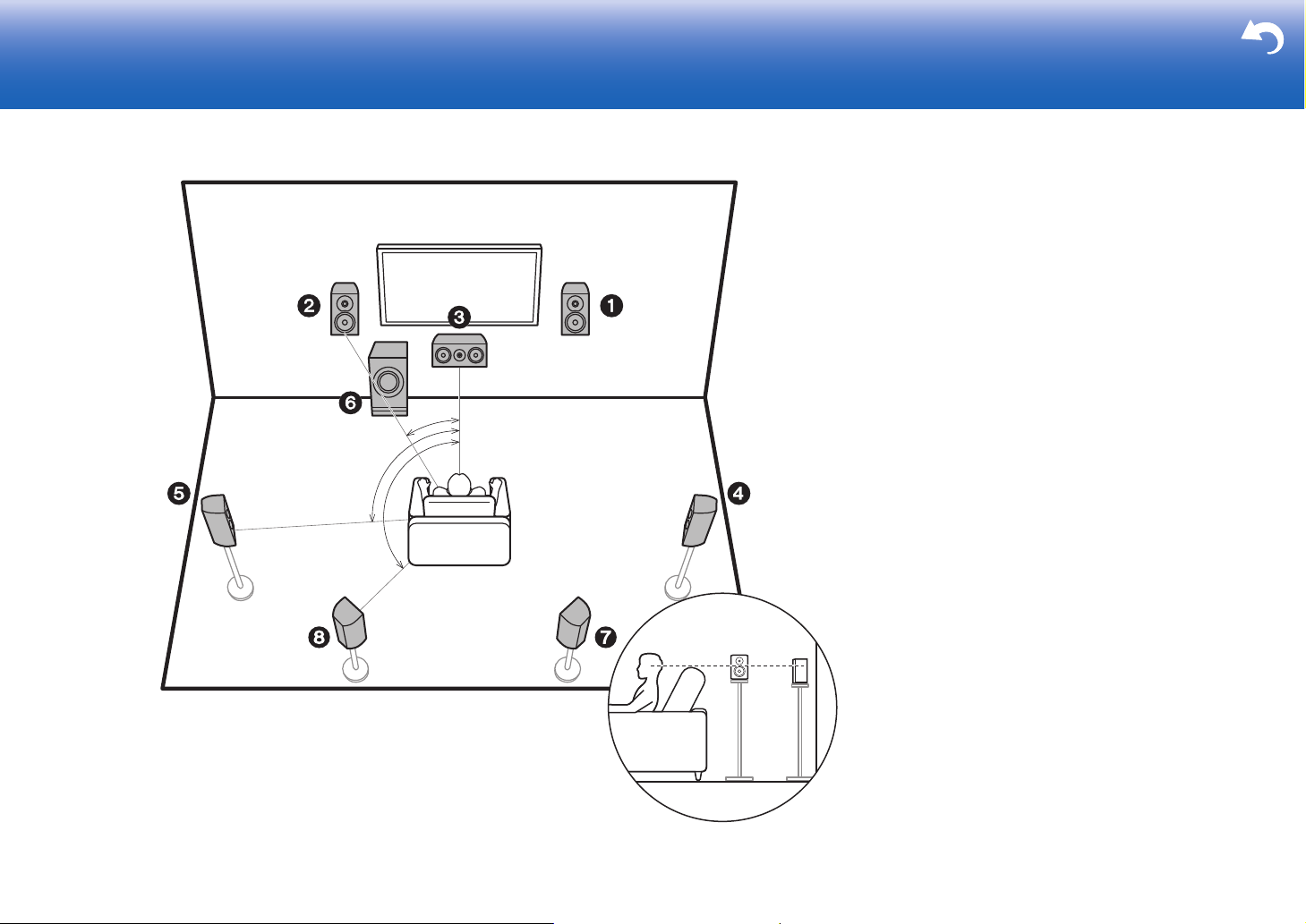
½1: 22e to 30e, ½2: 90e to 110e, ½3: 135e to 150e
7.1 Channel System
Front speakers output front stereo sound and a center
speaker outputs center sound such as dialogs and vocals.
Surround speakers create back sound field. Powered
subwoofer reproduces bass sounds and creates rich sound
field.
This basic 5.1 Channel System with surround back
speakers added is called a 7.1 Channel System. The
connection of surround back speakers improves the sense
of envelopment and connectivity of sound created by the
back sound field and provides a more real sound field.
Furthermore, by installing surround back speakers, you can
select the Dolby Atmos listening mode, which realizes the
most up-to-date 3D sound, when the input format is Dolby
Atmos.
The front speakers should be positioned at ear height, while
the surround speakers should be positioned just above ear
height. Center speaker should be set up facing the listening
position. Placing the powered subwoofer between the
center speaker and a front speaker gives you a natural
sound even when playing music. The optimal positioning is
for surround back speakers to be at ear height.
0 If you are including surround back speakers in the setup,
surround speakers are required.
0 "Speaker combinations" (P14) introduces some detailed
examples of speaker combinations.
1,2 Front Speakers
3 Center Speaker
4,5 Surround Speakers
6 Powered Subwoofer
7,8 Surround Back Speakers
8
Page 9
> Before Start > Part Names >Install > Initial Setup > Playback > Advanced Manual
Troubleshooting | Supplementary Information, etc.
*
1
*
2
*
3
Speaker B Speaker B
½1: 22e to 30e, ½2: 90e to 110e, ½3: 135e to 150e
En
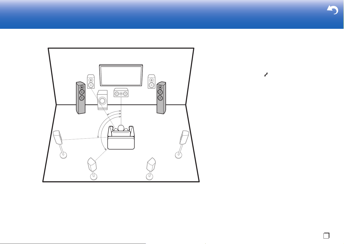
Speaker B System
With a 7.1 channel system (P8), you can connect one more
set of front speakers to use as a Speaker B System. In this
state, the 7.1 channel system becomes the Speaker A
System and you can switch the same audio to output from
A, B, or A+B. Press on the remote control (P6) and use
"Other" - "Speakers" to switch. Note that no sound is played
from the surround back speakers when playing from A+B.
0 "Speaker combinations" (P14) introduces some detailed
examples of speaker combinations.
9
Page 10
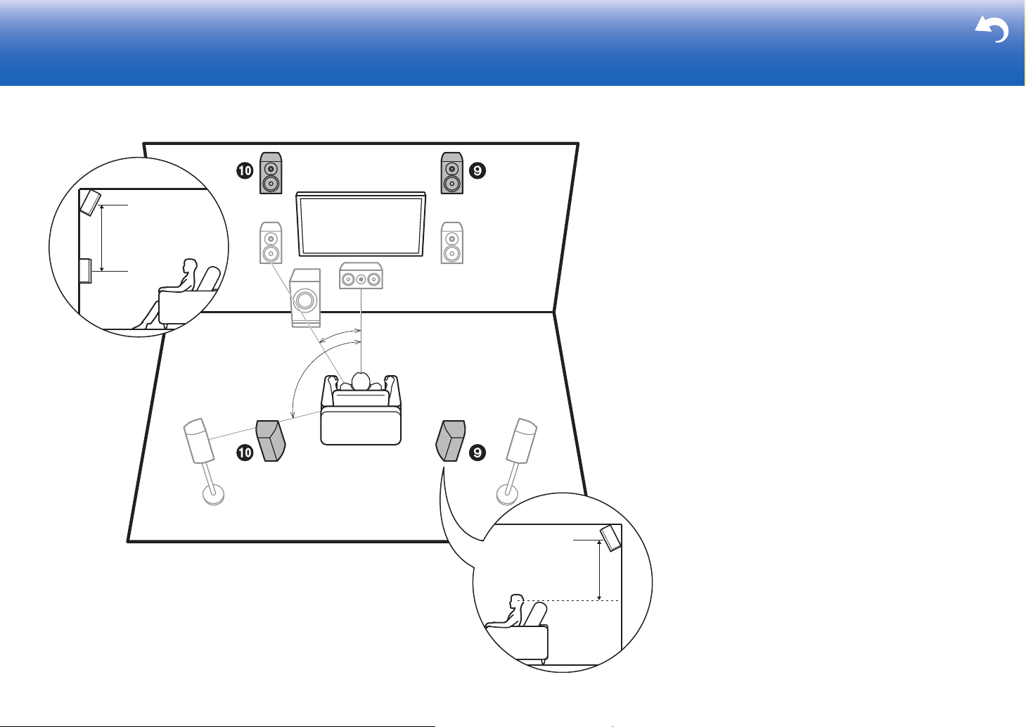
5.1.2 Channel System-1
> Before Start > Part Names >Install > Initial Setup > Playback > Advanced Manual
Troubleshooting | Supplementary Information, etc.
*
1
*
2
3´ (0.9 m)
or more
3´ (0.9 m)
or more
½1: 22e to 30e, ½2: 120e
(Front High Speakers/Rear High Speakers)
This is a basic 5.1 channel system consisting of front
speakers, a center speaker, surround speakers, and a
powered subwoofer, with the addition of front height
speakers or rear high speakers, which are both types of
height speakers. By installing height speakers, you can
select the Dolby Atmos listening mode, which realizes the
most up-to-date 3D sound including overhead sounds,
when the input format is Dolby Atmos. Front high speakers
or rear high speakers should be situated at least 3´/0.9 m
higher than the front speakers. Front high speakers should
be situated directly above the front speakers and the
distance between the rear high speakers should match the
distance between the front speakers. Both should be set up
facing the listening position.
0 "Speaker combinations" (P14) introduces some detailed
examples of speaker combinations.
9,10 Height Speakers
Choose one of the following:
0Front High Speakers
0Rear High Speakers
10
Page 11
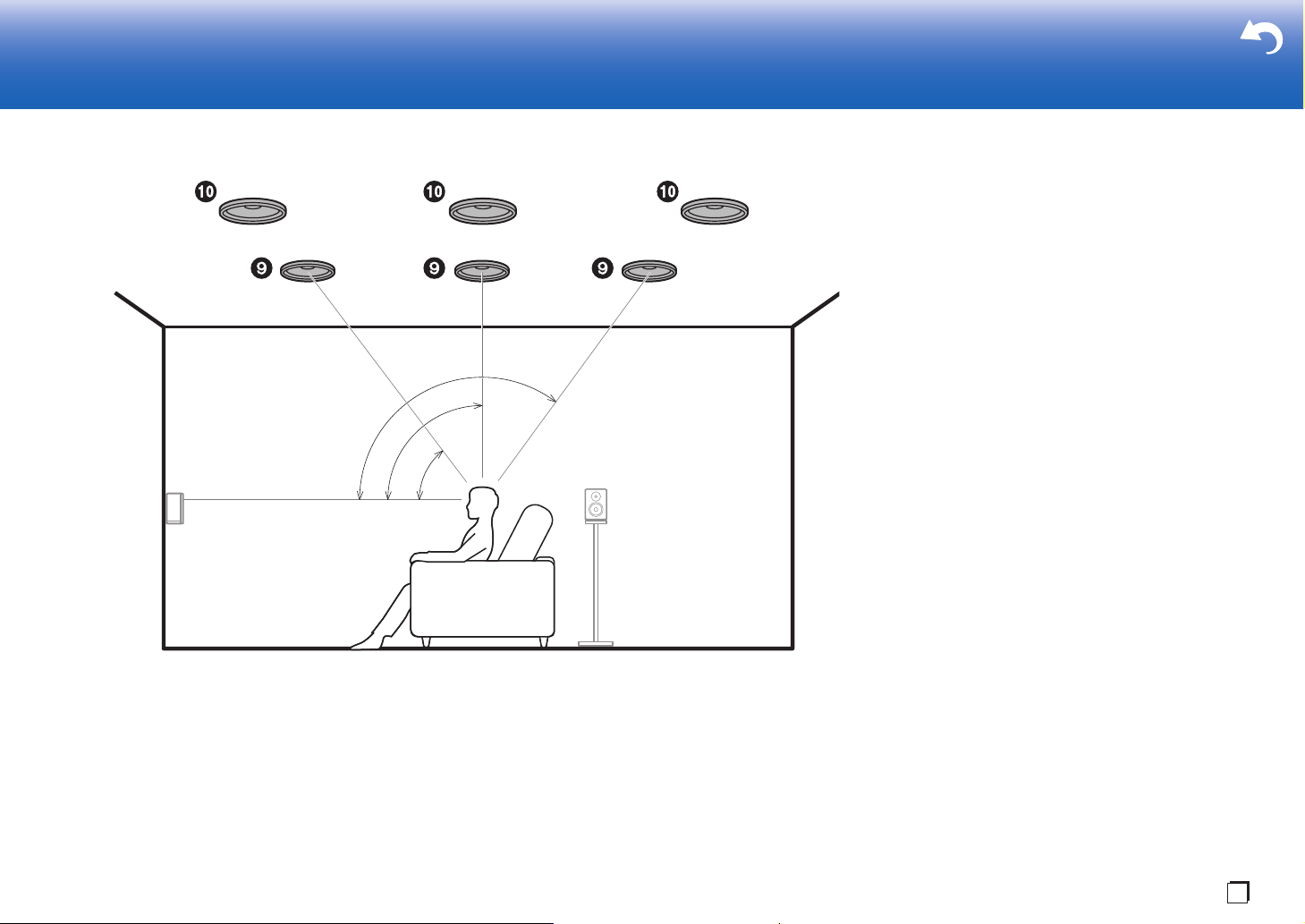
5.1.2 Channel System-2
> Before Start > Part Names >Install > Initial Setup > Playback > Advanced Manual
Troubleshooting | Supplementary Information, etc.
*
1
*
2
*
3
½1: 30e to 55e, ½2: 65e to 100e, ½3: 125e to 150e
En
(Ceiling Speakers)
This is a basic 5.1 channel system consisting of front
speakers, a center speaker, surround speakers, and a
powered subwoofer, with the addition of top front speakers,
top middle speakers, or top rear speakers, which are types
of height speakers. By installing height speakers, you can
select the Dolby Atmos listening mode, which realizes the
most up-to-date 3D sound including overhead sounds,
when the input format is Dolby Atmos. Fit top front speakers
on the ceiling forward of the seating position, top middle
speakers on the ceiling directly above the seating position,
and top rear speakers on the ceiling behind the seating
position. The distance between each pair should match the
distance between the two front speakers.
0 Dolby Laboratories recommends placing this type of
height speakers to obtain the best Dolby Atmos effect.
0 "Speaker combinations" (P14) introduces some detailed
examples of speaker combinations.
9,10 Height Speakers
Choose one of the following:
0Top Front Speakers
0Top Middle Speakers
0Top Rear Speakers
11
Page 12
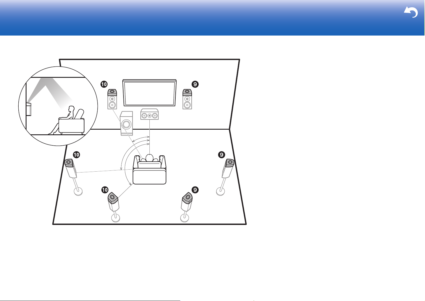
5.1.2 Channel System-3
> Before Start > Part Names >Install > Initial Setup > Playback > Advanced Manual
Troubleshooting | Supplementary Information, etc.
*
1
*
2
*
3
½1: 22e to 30e, ½2: 90e to 120e, ½3: 135e to 150e
(Dolby Enabled Speakers (Dolby Speakers))
This is a basic 5.1 channel system consisting of front
speakers, a center speaker, surround speakers, and a
powered subwoofer, with the addition of Dolby enabled
speakers (front), Dolby enabled speakers (surround) or
Dolby enabled speakers (surround back) which are both
types of height speakers. Dolby enabled speakers are
special speakers designed to face the ceiling so that sound
is heard after bouncing off the ceiling so that sound appears
to be coming from overhead. By installing height speakers,
you can select the Dolby Atmos listening mode, which
realizes the most up-to-date 3D sound including overhead
sounds, when the input format is Dolby Atmos.
Place them either above the front speakers, above the
surround speakers or above surround back speakers.
0 "Speaker combinations" (P14) introduces some detailed
examples of speaker combinations.
9,10 Height Speakers
Choose one of the following:
0 Dolby Enabled Speakers (Front)
0 Dolby Enabled Speakers (Surround)
0 Dolby Enabled Speakers (Surround Back)
12
Page 13
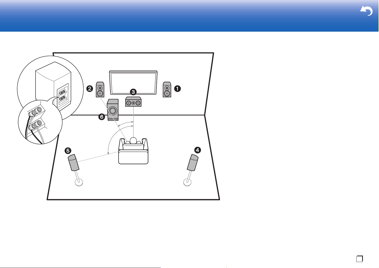
Bi-Amping the Speakers
> Before Start > Part Names >Install > Initial Setup > Playback > Advanced Manual
Troubleshooting | Supplementary Information, etc.
*
1
*
2
½1: 22e to 30e, ½2: 120e
En
With a 5.1 channel system, it is possible to connect front
speakers that support Bi-Amping to improve the quality of
the bass and treble. Bi-Amping compatible speakers need
their terminals for the tweeters connected to one amplifier
and their terminals for woofers connected to another
amplifier, so it is not possible to connect height speakers
and surround back speakers with this connection. Other
than front speakers, you can also connect a center speaker,
surround speakers, and a powered subwoofer.
0 "Speaker combinations" (P14) introduces some detailed
examples of speaker combinations.
1,2 Front Speakers (Bi-Amping)
3 Center Speaker
4,5 Surround Speakers
6 Powered Subwoofer
13
Page 14
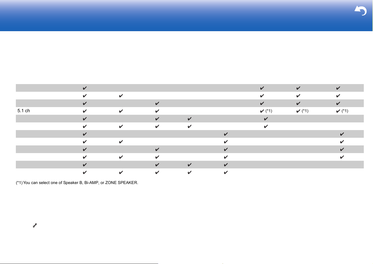
Speaker combinations
> Before Start > Part Names >Install > Initial Setup > Playback > Advanced Manual
Troubleshooting | Supplementary Information, etc.
0 In any of the combinations, up to two powered subwoofers can be connected.
SURROUND
Speaker Channels FRONT CENTER SURROUND
BACK HEIGHT
2.1 ch
3.1 ch
4.1 ch
5.1 ch
6.1 ch
7.1 ch
2.1.2 ch
3.1.2 ch
4.1.2 ch
5.1.2 ch
6.1.2 ch
7.1.2 ch
(*1) You can select one of Speaker B, Bi-AMP, or ZONE SPEAKER.
(*2) When using Speakers B, no sound is played from the surround back speakers when
playing from A+B.
(*3) No sound is played from the height speakers when playing audio from ZONE
SPEAKER.
(*4) You can connect both surround back speakers and height speakers. However, you can
only output audio from one of these at a time. When both are connected, you can set
which speakers to prioritize.
0 Press on the remote control (P6) and use "Other" - "Speakers" to switch speakers A
and B and to switch between surround back speakers and height speakers.
(*2)
(*2)
(*3)
(*3)
(*3)
(*3)
(*4) (*4)
(*4) (*4)
SP B
(Speaker B)
(*1) (*1) (*1)
(*1) (*1) (*1)
(*1) (*1) (*1)
(*1) (*1) (*1)
Bi-AMP
(ZONE SPEAKER)
ZONE 2
(P21)
14
Page 15
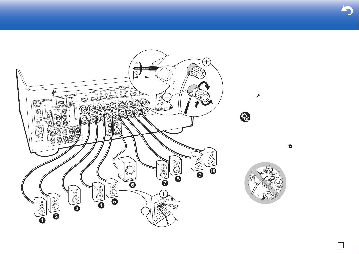
Step2: Connect the Speakers
> Before Start > Part Names >Install > Initial Setup > Playback > Advanced Manual
Troubleshooting | Supplementary Information, etc.
a
b
OR
Speaker B
1/2˝
(12 mm)
a Speaker cable, b Subwoofer cable
En
Standard Connections (Pages 8 to 12)
Connect 12345678 for a 7.1 channel system.
Connect 1234569: for a 5.1.2 channel system. Up
to two powered subwoofers can be connected. The same
signal is output from each of the SUBWOOFER PRE OUT
jacks.
0
You can also connect both 78 and 9:. However, you can
only output audio from one of these at a time. When both
are connected, you can switch which speakers to prioritize.
Press on the remote control (P6) and use "Other" "Speakers" to switch between surround back speakers and
height speakers and to switch speakers A and B.
Setup
0 Settings for the speaker configuration you have
connected need to be made in "1. Full Auto
MCACC" in Initial Setup (P23).
0
If any of the connected speakers have an impedance of
4 Ω or more to less than 6 Ω, after completing Initial
Setup, you need to make some settings in the System
Setup menu. Press on the remote controller, and in
the Home displayed set "System Setup" - "Speaker" "Configuration" - "Speaker Impedance" to "4ohms".
Make sure the exposed wires of the speakers do
not stick out of the speaker terminals when
connecting. If the exposed wires of the speakers
touch the rear panel or the + and – wires touch
each other, the protection circuit will be activated.
15
Page 16
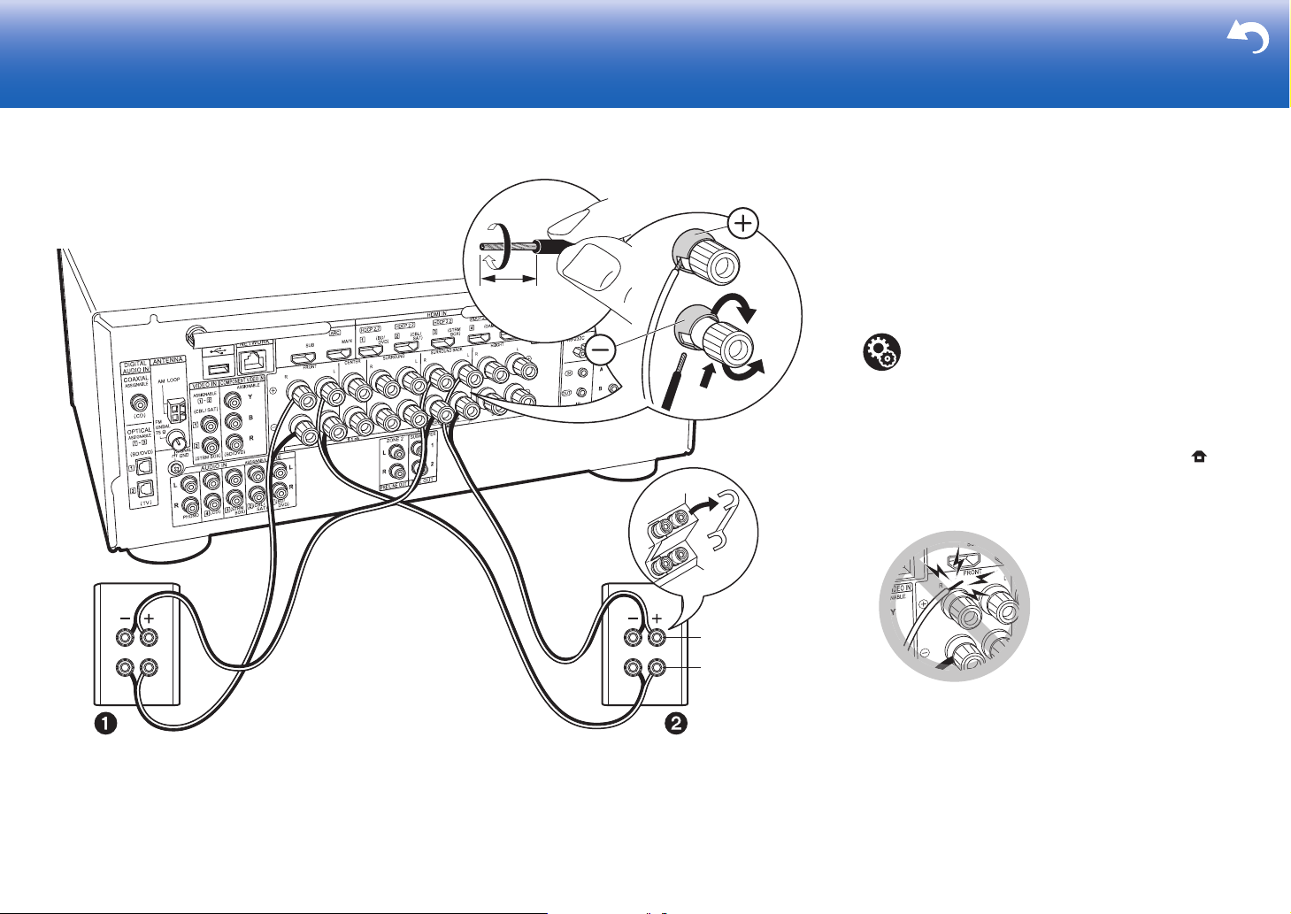
> Before Start > Part Names >Install > Initial Setup > Playback > Advanced Manual
Troubleshooting | Supplementary Information, etc.
a
1/2˝
(12 mm)
For highfrequency
For lowfrequency
a Speaker cable
Connecting with Bi-Amping Speakers (Page 13)
Make sure you remove the jumper bar fitted between the
woofer jacks and tweeter jacks of the front speakers.
to "Standard Connections (Pages 8 to 12)" (P15) to connect
the center speaker, surround speakers, and powered
subwoofer.
0 Also refer to the instruction manual for your speakers
when using connections for Bi-Amping.
Setup
0 Settings for the speaker configuration you have
connected need to be made in "1. Full Auto
MCACC" in Initial Setup (P23).
0 If any of the connected speakers have an
impedance of 4 Ω or more to less than 6 Ω, after
completing Initial Setup, you need to make some
settings in the System Setup menu. Press on
the remote controller, and in the Home displayed
set "System Setup" - "Speaker" - "Configuration" "Speaker Impedance" to "4ohms".
Refer
Make sure the exposed wires of the speakers
do not stick out of the speaker terminals when
connecting. If the exposed wires of the
speakers touch the rear panel or the + and –
wires touch each other, the protection circuit
will be activated.
16
Page 17
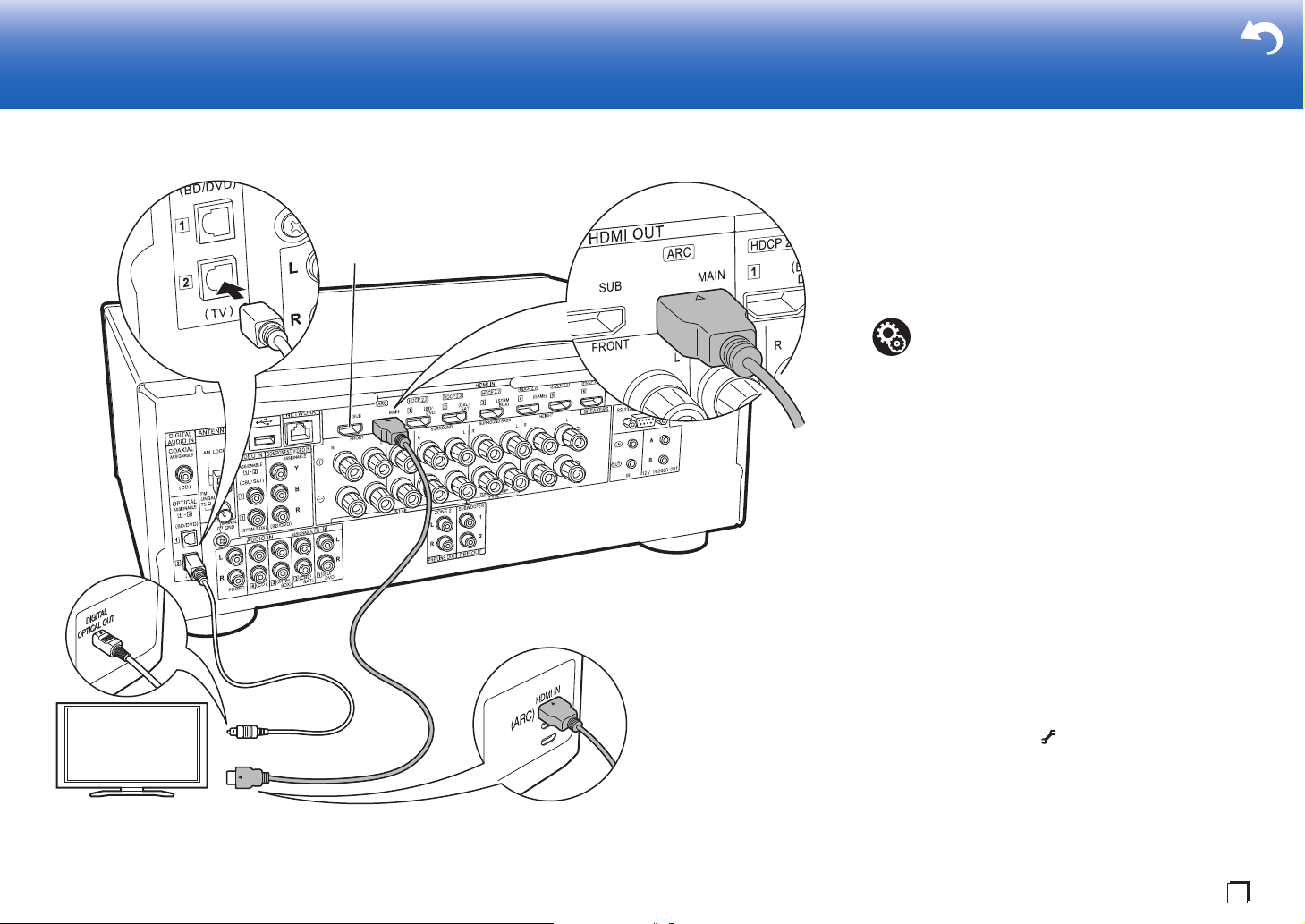
Step3: Connect the TV & AV Components
> Before Start > Part Names >Install > Initial Setup > Playback > Advanced Manual
Troubleshooting | Supplementary Information, etc.
TV
*2
a
b
a HDMI cable, b Digital optical cable
En
1. Connect the TV
To ARC TV
For a TV that supports the ARC (Audio Return Channel)
feature (*1), use an HDMI cable and connect according to
illustration "a". Choose an HDMI IN jack on the TV that
supports ARC when connecting.
Setup
0 Settings are required to use the ARC function.
Select "Yes" in "5. Audio Return Channel" (P24)
in the Initial Setup.
0 Refer to the instruction manual for the TV for TV
connections and instructions regarding settings
for CEC features and audio output.
To Non-ARC TV
For a TV that does not support the ARC (Audio Return
Channel) feature (*1), connect both the HDMI cable in
illustration "a" and the digital optical cable in "b".
0 Connection with a digital optical cable is not necessary if
you will watch TV through a device such as a cable settop box (that is, not use a tuner built into the TV) that you
have connected to the input jack on this unit.
(*1) The ARC feature: This feature transfers TV audio
signals via HDMI cable so that you can play the audio
from the TV through this unit. Connection to an ARC
compatible TV is complete with one HDMI cable. Refer
to the instruction manual for your TV to see if it
supports ARC.
(*2) Another TV or projector can be connected to the HDMI
OUT SUB jack. Press (P6) on the remote control
and use "Other" - "HDMI Out" to switch between MAIN
and SUB. Note that this jack does not support ARC.
17
Page 18
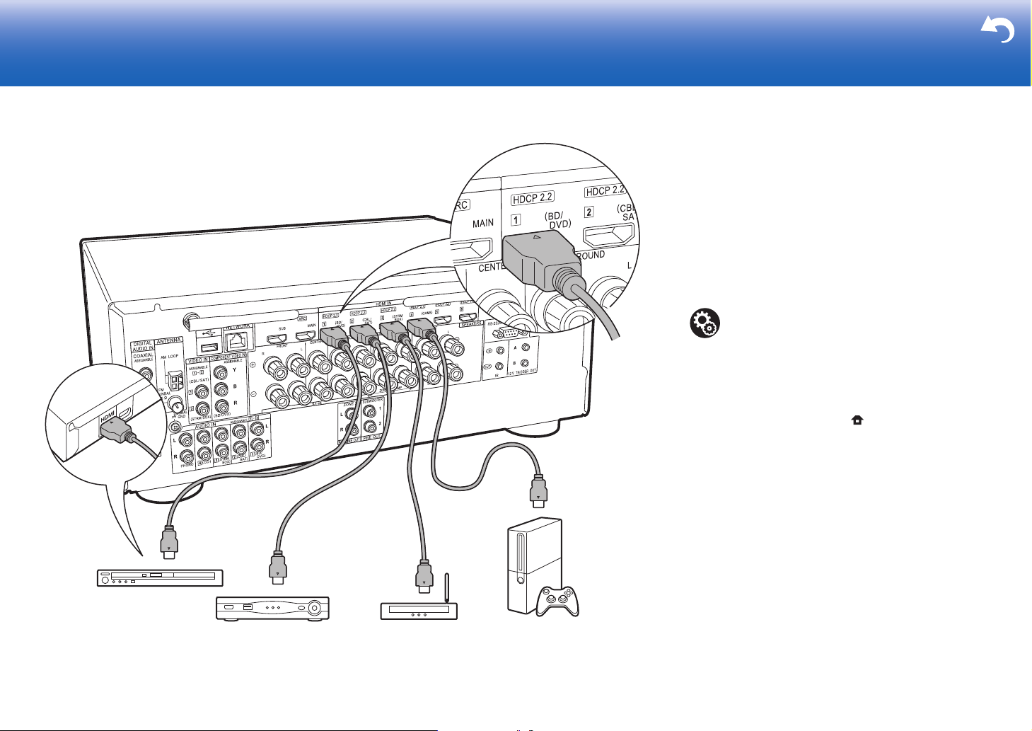
2. Connect the HDMI AV Component
> Before Start > Part Names >Install > Initial Setup > Playback > Advanced Manual
Troubleshooting | Supplementary Information, etc.
BD/DVD
GAME
a
Cable/Satellite set-top
box
Streaming media
player
a HDMI cable
This is an example of connection with an AV component
that has an HDMI jack. With connection to an AV
component that conforms with the CEC (Consumer
Electronics Control) standard, you can use features such as
the HDMI CEC feature (*) that links with the input selector,
and the HDMI Standby Through feature which allows you to
play video and audio from AV components on the TV even
when this unit is in standby mode.
0 To play 4K or 1080p video, use a high speed HDMI
cable.
Setup
0 When "Yes" is selected for "5. Audio Return
Channel" in Initial Setup (P24), the HDMI CEC
function and HDMI Standby Through function are
automatically enabled. If "No, Skip" is selected,
settings are required in the System Setup menu
after Initial Setup is complete. Settings are made
in "System Setup" - "Hardware" - "HDMI" in Home
displayed by pressing on the remote
controller.
0 To enjoy digital surround sound including Dolby
Digital, audio output should be set to "Bitstream
output" on the connected Blu-ray Disc player or
other device.
(*)The HDMI CEC feature: You can control features such
as linking input switching with the input selector and
players conforming to the CEC standard, switching audio
to output it from the TV or from this unit, and adjusting
the volume using the remote controller of a CECcompliant TV, and automatically switching this unit to
standby when the TV is turned off.
18
Page 19
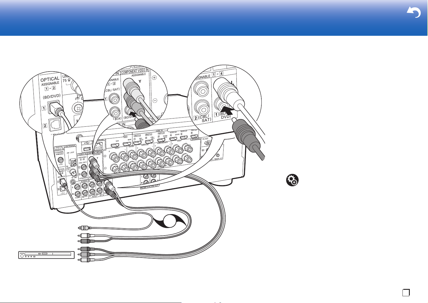
3. Connect the Non-HDMI AV Component
> Before Start > Part Names >Install > Initial Setup > Playback > Advanced Manual
Troubleshooting | Supplementary Information, etc.
BD/DVD
OR
a
b
c
a Component video cable, b Digital optical cable, c Analog audio cable
En
This is an example of connection with an AV component
that does not have an HDMI jack. Make the connections to
the AV component to match the jacks it has. When video
input connection is to the BD/DVD jack, the audio input
connection should also be to the BD/DVD jacks, and so on,
so that you connect the video input jacks to the jacks with
the same name as the audio input jacks.
Note that video signals input to the VIDEO IN jack or the
COMPONENT VIDEO IN jack will be converted to HDMI
video signals and then output from the HDMI OUT jack.
0 To enjoy digital surround playback in formats such as
Dolby Digital, you need to make a connection for audio
signals with a digital coaxial cable or a digital optical
cable.
0 It is possible to change assignment of the input jacks you
see in the illustration at left, so you can also connect to
any jack other than BD/DVD. For details, see the
Advanced Manual.
Setup
0 The COMPONENT VIDEO IN jacks are
compatible only with 480i or 576i resolution.
When you connect to the COMPONENT VIDEO
IN jacks, set the output resolution of the player to
480i or 576i. Select interlace if there is no option
for 480i, etc. If your player does not support 480i
or 576i output, use the VIDEO IN jack.
0 To enjoy digital surround sound including Dolby
Digital, audio output should be set to "Bitstream
output" on the connected Blu-ray Disc player or
other device.
19
Page 20
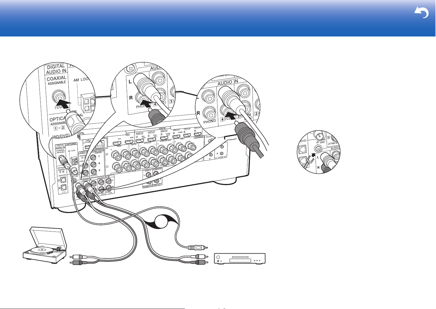
4. Connect the Audio Component
> Before Start > Part Names >Install > Initial Setup > Playback > Advanced Manual
Troubleshooting | Supplementary Information, etc.
CD
OR
a
b
Turntabl e
a Digital coaxial cable, b Analog audio cable
Example of a connection with an audio component.
Connect a CD player using a digital coaxial cable or an
analog audio cable. You can also connect a turntable that
has an MM-type cartridge to the PHONO jack.
0 If the turntable has a built-in audio equalizer, connect it to
another AUDIO IN jack. Further, if the turntable uses an
MC type cartridge, install an audio equalizer compatible
with the MC type cartridge between the unit and the
turntable, then connect to any AUDIO IN jack other than
the PHONO jack.
If the turntable has a ground wire,
connect it to the SIGNAL GND terminal of this unit.
20
Page 21
5. Multi-zone Connection
> Before Start > Part Names >Install > Initial Setup > Playback > Advanced Manual
Troubleshooting | Supplementary Information, etc.
ZONE2 PRE/LINE OUT
ZONE SPEAKER
ZONE2
LINE
IN
BD/DVD
OR
MAIN ROOM
c
a
b
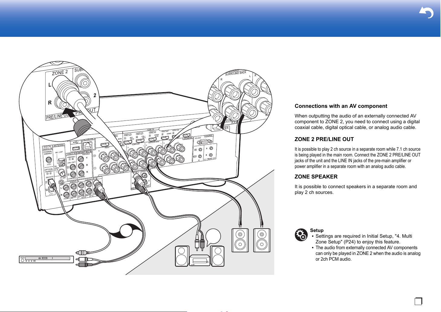
a Digital optical cable, b Analog audio cable, c Speaker cable
En
You can enjoy audio in the separate room by, for example, playing
a Blu-ray Disc player in the main room (where this unit is located)
and listening to internet radio in the separate room (ZONE 2).
0 DSD and Dolby TrueHD audio signals are not output to
ZONE 2 when selected with the "NET" input selector.
Connections with an AV component
When outputting the audio of an externally connected AV
component to ZONE 2, you need to connect using a digital
coaxial cable, digital optical cable, or analog audio cable.
ZONE 2 PRE/LINE OUT
It is possible to play 2 ch source in a separate room while 7.1 ch source
is being played in the main room. Connect the ZONE 2 PRE/LINE OUT
jacks of the unit and the LINE IN jacks of the pre-main amplifier or
power amplifier in a separate room with an analog audio cable.
ZONE SPEAKER
It is possible to connect speakers in a separate room and
play 2 ch sources.
0 You cannot use ZONE SPEAKER if you have connected
the front speakers using Bi-Amping connection or if you
have connected a Speakers B System.
0 No sound is played from the height speakers when
playing audio from ZONE SPEAKER.
Setup
0 Settings are required in Initial Setup, "4. Multi
Zone Setup" (P24) to enjoy this feature.
0
The audio from externally connected AV components
can only be played in ZONE 2 when the audio is analog
or 2ch PCM audio. If you have connected to this unit
with a digital coaxial cable or digital optical cable, it may
be necessary to change the audio output of the AV
component to PCM output.
21
Page 22
6. Connect Other Cables
> Before Start > Part Names >Install > Initial Setup > Playback > Advanced Manual
Troubleshooting | Supplementary Information, etc.
a
c
d
b
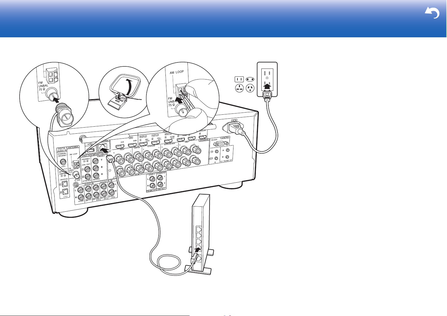
a Indoor FM antenna, b AM loop antenna, c Ethernet cable, d Power cord
Antenna Hookup
Move the antenna around while playing the radio to find the
position with the best reception. Use a thumb tack or similar
to attach the indoor FM antenna to a wall.
Network Hookup
Connect this unit to the network using wired LAN or Wi-Fi
(wireless LAN). You can enjoy network features such as
internet radio by connecting the unit to the network. If you
connect by wired LAN, connect with an Ethernet cable to
the NETWORK port as shown in the illustration. To connect
by Wi-Fi, then after selecting "Wireless" in "3. Network
Connection" (P24) in Initial Setup, select the desired setting
method and follow the onscreen instructions to configure
the connection.
Power Cord Hookup
This unit includes removable power cords. Connect the
power cord to the power outlet after completing all other
connections. Connect the power cord to AC IN of the unit
and then connect to the outlet. Always disconnect the outlet
side first when disconnecting the power cord.
22
Page 23
Initial Setup
> Before Start > Part Names > Install > Initial Setup > Playback > Advanced Manual
Troubleshooting | Supplementary Information, etc.
1
2 3
INPUT
a
b
En
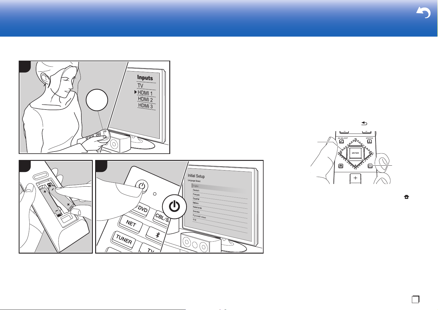
Initial Setup with Auto Start-up Wizard
Initial Setup Starts Automatically
When you turn the unit on for the first time after purchasing
it, Initial Setup is automatically shown on the TV to enable
you to make settings required for startup using simple
operations following onscreen guidance.
1. Switch the input on the TV to that assigned to the unit.
2. Put batteries into the remote controller of this unit.
3. Press Í on the remote controller to turn the unit on.
4. Select the item with the cursors of the remote controller
and press ENTER (a) to confirm your selection. To return
TV
to the previous screen, press (b).
0 If you terminate the procedure on the way or want to
change a setting made during Initial Setup, press on
the remote controller, and from the Home select "System
Setup" - "Miscellaneous" - "Initial Setup", and press
ENTER.
∫ 1. Full Auto MCACC
Place the supplied speaker setup microphone in the
listening position, measure the test tones emitted by the
speakers, then the unit automatically sets the optimum
volume level for each speaker, the crossover frequencies,
and the distance from the listening position. This also
automatically adjusts the equalizers for the speakers and
enables correction of distortion caused by the acoustic
environment of the room.
23
Page 24
0 Calibration takes between 3 and 12 minutes to be
MCACC
SETUP MIC
> Before Start > Part Names > Install > Initial Setup > Playback > Advanced Manual
Troubleshooting | Supplementary Information, etc.
completed. The speakers emit the test tone at high
volume during measurement, so be careful of your
surroundings. Keep the room as quiet as possible during
measurement.
0 If you have connected a subwoofer, check the power and
volume of the subwoofer. Set the subwoofer volume to
more than halfway.
0 If the power of this unit suddenly turns off, the wires in
the speaker cables may have touch the rear panel or
other wires and tripped the protection circuit. Twist the
wires again properly and make sure they do not stick out
of the speaker terminals when connecting.
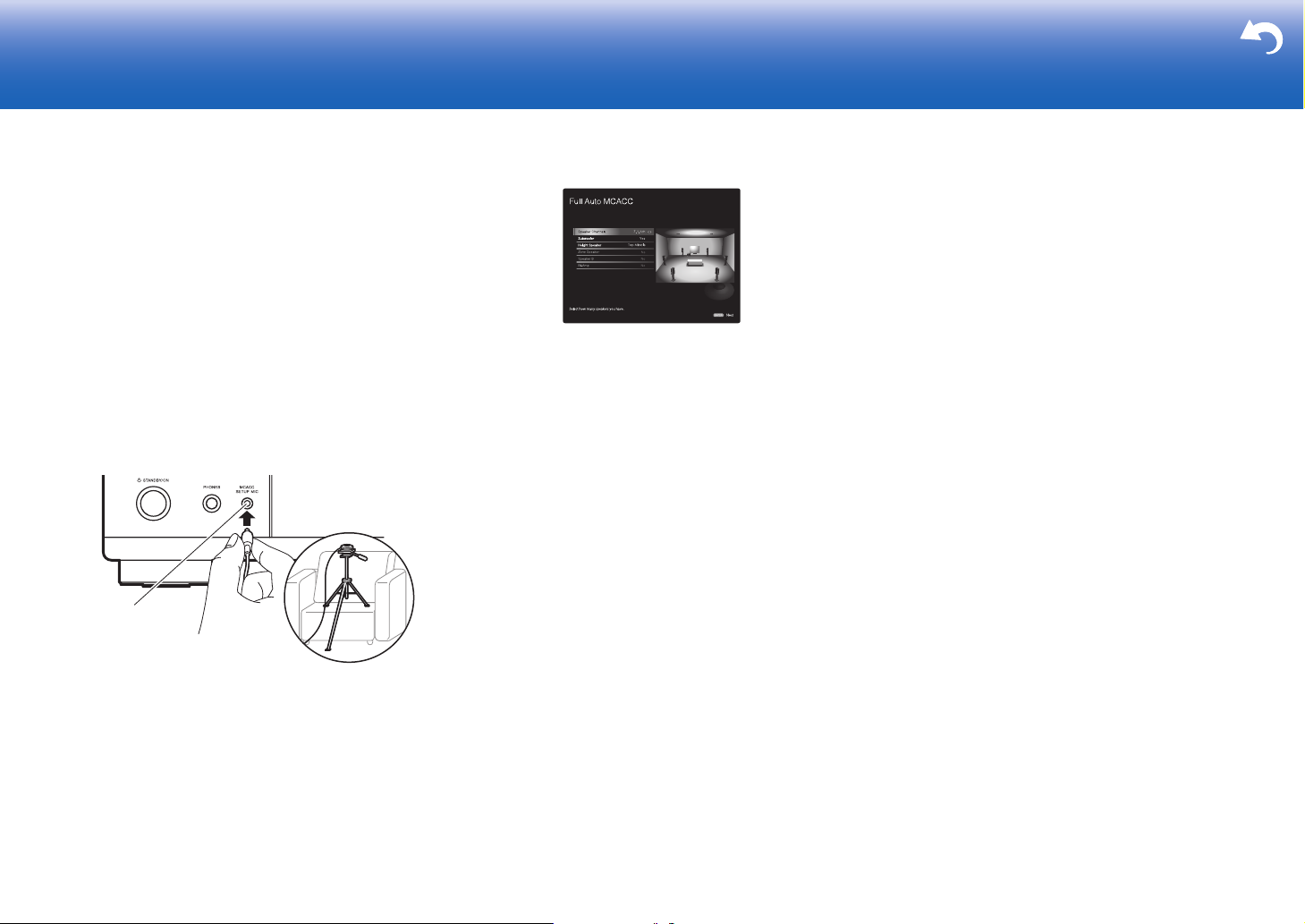
1. Place the supplied speaker setup microphone in the
listening position, and connect to the MCACC SETUP
MIC jack on the main unit.
The image on the screen changes as you choose the
number of channels in "Speaker Channels", so refer to it
when performing the settings.
3. Test tones are emitted by the speakers, and firstly the
unit detects the speakers connected and the noise in the
environment.
4. After the results of the above measurements are
displayed, select "Next", press ENTER on the remote
controller, and the test tones are emitted again, and the
unit automatically makes settings such as the optimum
volume level and the crossover frequency.
5. When the measurement is completed, the measurement
result is displayed. Press the cursors / on the
remote controller to check the settings. Press ENTER
when "Save" is selected to save the settings.
6. Disconnect the speaker setup microphone.
∫ 2. Source Connection
Check that each input source is connected correctly. Follow
When putting the speaker setup microphone on a tripod,
refer to the illustration when putting it in place.
2. Select the connected speaker configuration.
the guidance, select the input you want to confirm, start
play of the selected player, and confirm that the images
appear on the TV and that sound is played.
∫ 3. Network Connection
Set up Wi-Fi connection with an access point such as a wireless LAN
router. There are the following two methods of connecting by Wi-Fi:
"Scan Networks": Search for an access point from this
unit. Find out the SSID of the access point beforehand.
"Use iOS Device (iOS7 or later)": Share the iOS device's
Wi-Fi settings with this unit.
If you select "Scan Networks", there are a further two
choices of connection method. Check the following.
"Enter Password": Enter the password (or key) of the
access point to connect.
"Push Button":
button, you can connect without entering a password.
0 If the SSID of the access point is not displayed, then in
the screen listing the SSIDs, select "Other..." with the
cursor on the remote controller and press ENTER, then
follow the onscreen instructions.
Keyboard Input
To switch between upper and lower case, select "A/a" on the
screen and press ENTER. To select whether to mask the
password with "
remote controller. Press CLEAR to delete all the input characters.
0 A confirmation screen asking you to agree to the privacy
policy is displayed during network setting. Select
"Accept" and press ENTER to indicate agreement.
If the access point has an automatic connection
½
" or display it in plain text, press +Fav on the
∫ 4. Multi Zone Setup
When you want to enjoy audio in a room other than the main room, set
the audio output method for the separate room (ZONE 2). If you have
connected speakers in a separate room with speaker cable, select
"Using AV Receiver". If you have connected a pre-main amplifier in a
separate room with an analog audio cable, select "with External
Premain Amplifier". If you have connected a power amplifier, select
"with External Power Amplifier".
∫ 5. Audio Return Channel
If you have connected a TV that supports ARC, select
"Yes". This unit's ARC setting turns on and you can listen to
the TV's audio through this unit.
0 If you select "Yes", the HDMI CEC function is enabled
and power consumption increases during standby.
24
Page 25
Playback
> Before Start > Part Names > Install > Initial Setup >Playback > Advanced Manual
Troubleshooting | Supplementary Information, etc.
1 2
INPUT
b
a
1 2 3
En
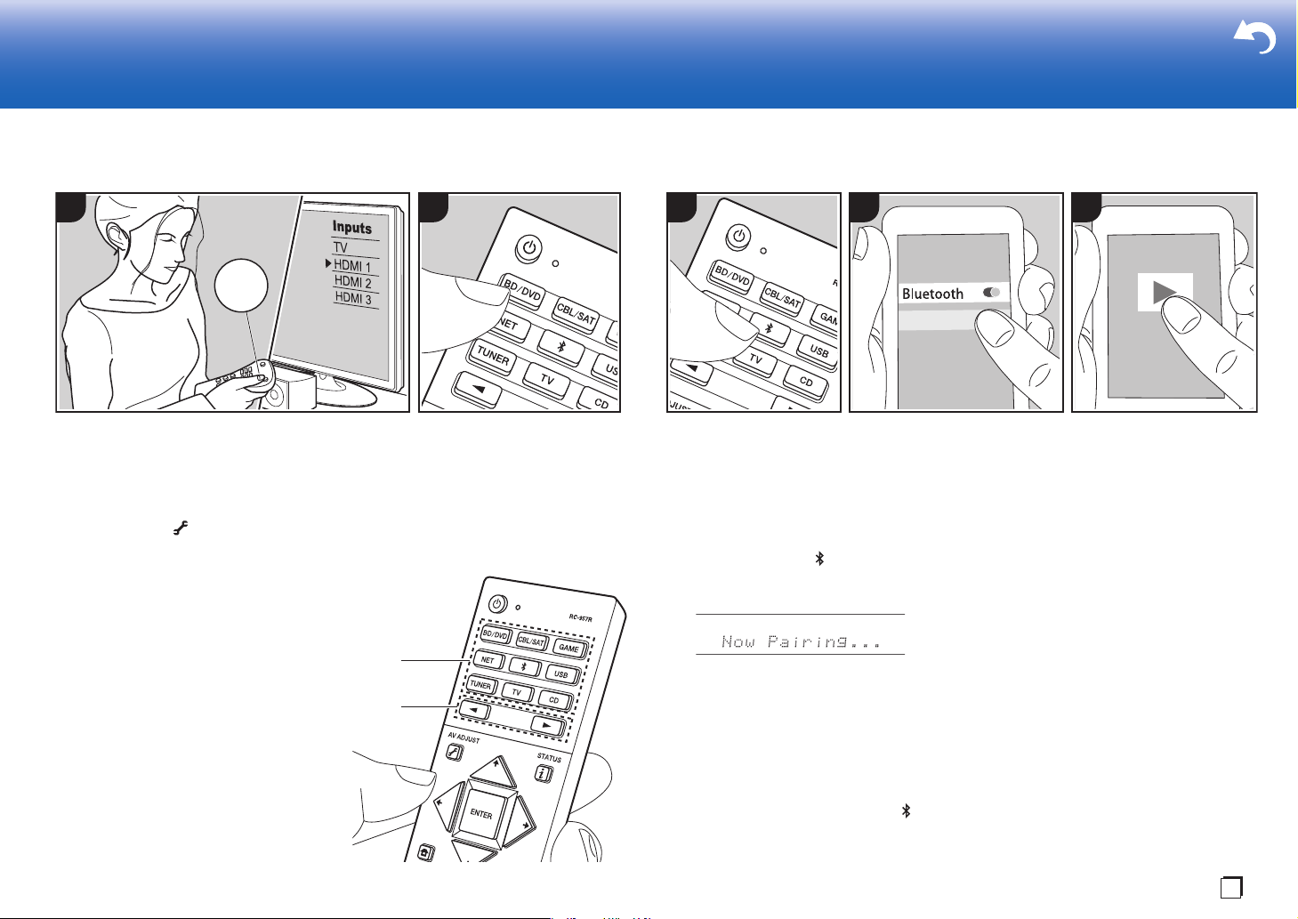
AV Component Playback
TV
Basic Operations
You can play the audio from AV components
such as Blu-ray Disc players through this unit.
0
When a TV is connected to the HDMI OUT
SUB jack, press (P6) on the remote
controller and use "Other" - "HDMI Out" to
switch between MAIN and SUB.
Perform the following procedure when the
unit is on.
1. Switch the input on the TV to that
assigned to the unit.
2. Press the input selector (a) on the
remote controller with the same name as
the jack to which you connected the
player to switch the input.
For example, press BD/DVD to play the
player connected to the BD/DVD jack.
Press TV to listen the TV's sound. To play
a device connected to the STRM BOX,
PHONO, HDMI5, HDMI6 jack or the AUX
INPUT AUDIO/HDMI jack on the front
panel, press
the input.
21
(b) repeatedly to select
0 When the CEC link function works,
the input switches automatically when
you have connected a CEC compliant
TV and player to this unit using HDMI
connection.
3. Start play on the AV component.
BLUETOOTH® Playback
PioneerVSX-LX302XXX
You can wirelessly play music on a
smartphone or other BLUETOOTH
enabled device. Perform the following
procedure when the unit is on.
Pairing
1. When you press the button, "Now
Pairing..." is displayed on this unit's
display, and the pairing mode is enabled.
2. Enable (turn on) the BLUETOOTH
function of the BLUETOOTH enabled
device, then select this unit from
amongst the devices displayed. If a
password is requested, enter "0000".
0 This unit is displayed as "Pioneer
VSX-LX302 XXXXXX".
0 To connect another BLUETOOTH
enabled device, press and hold
until "Now Pairing..." is displayed,
then perform step 2. This unit can
store the data of up to 8 paired
devices.
0 The coverage area is 48´/15 m. Note
that connection is not always
guaranteed with all BLUETOOTH
enabled devices.
Playing Back
1. Perform the connection procedure on
the BLUETOOTH enabled device.
The input on this unit automatically
switches to "BLUETOOTH".
2. Play music. Increase the volume of the
BLUETOOTH enabled device to an
appropriate level.
0 Due to the characteristics of
BLUETOOTH wireless technology, the
sound produced on this unit may slightly
be behind the sound played on the
BLUETOOTH enabled device.
25
Page 26
Network Functions
> Before Start > Part Names > Install > Initial Setup >Playback > Advanced Manual
Troubleshooting | Supplementary Information, etc.
321
INPUT
b
a
c
TV
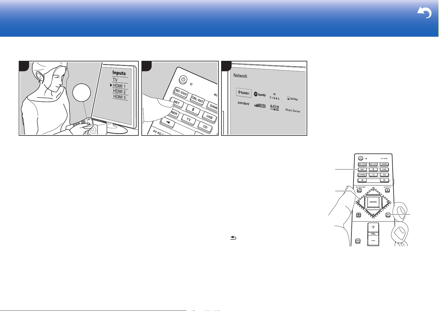
Basic Operations
By connecting this unit to the network you
can enjoy internet radio services such as
TuneIn, streaming from Spotify Connect,
and wireless playback using AirPlay
features. Furthermore, you can use the
Music Server feature to stream music files
stored on PCs or NAS devices that support
the home network feature. The basic
operations for Network Functions are
introduced in the Basic Manual. For more
advanced operations, see the Advanced
Manual. There may also be additional
network functions provided through
firmware updates for this unit. Also see the
Advanced Manual for information about
new features.
0 The network needs to be connected to
the internet in order to play internet radio
services.
0 Depending on the internet radio service,
the user may need to register from their
computer first.
0 To enable Spotify Connect, install the
®
Spotify application on your smartphone
or tablet and create a Spotify premium
account.
– Refer to the following for Spotify
settings:
www.spotify.com/connect/
0 The network servers compatible with the
Music Server feature are those PCs with
players installed that have the server
functionality of Windows Media
11 or 12, or NAS that are compatible
with home network functionality. Note
that with PCs, only music files registered
in the library of Windows Media
can be played.
0 You may need to make some settings on
the PC in advance to use Windows
®
Media
Player 11 or 12 with the Music
Server feature.
Perform the following procedure when the
unit is on.
1. Switch the input on the TV to that
assigned to the unit.
2. Press NET (a) on the remote controller
®
Player
®
Player
to display a list of Network Functions on
the TV.
3. Select the Network Function with the
cursors of the remote controller and
press ENTER (b) to confirm your
selection.
With internet radio services, follow the
on-screen instructions, using the cursors
to select radio stations and programs,
then press ENTER to play. With Spotify
or AirPlay, select this unit with your
smartphone to play. With Music Server,
select the server with the cursors, then
select the desired music file and press
ENTER to play.
0 To return to the previous screen, press
(c).
26
Page 27
USB Storage Device
> Before Start > Part Names > Install > Initial Setup >Playback > Advanced Manual
Troubleshooting | Supplementary Information, etc.
4321
INPUT
a
b
c
En
TV
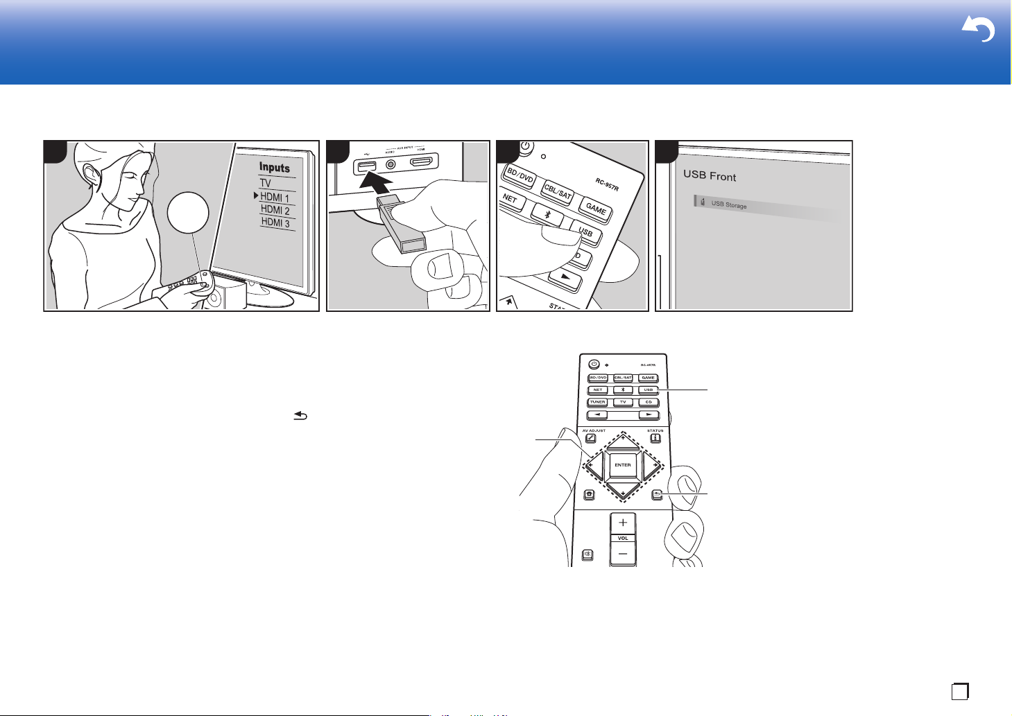
Basic Operations
You can play music files stored on a USB
storage device.
Perform the following procedure when the
unit is on.
1. Switch the input on the TV to that
assigned to the unit.
2. Plug your USB storage device with the
music files into the USB port either on
the front panel or rear panel of this unit.
3. Press USB (b) on the remote controller
and select "USB Front" or "USB Rear".
0 If the "USB" indicator flashes on the
display, check whether the USB
storage device is plugged in properly.
0 Do not unplug the USB storage
device while "Connecting···" is
appeared on the display. This may
cause data corruption or malfunction.
4. Press ENTER on the remote controller in
the next screen. The list of folders and
music files on the USB storage device
are displayed. Select the folder with the
cursors and press ENTER to confirm
your selection (a).
5. With the cursors on the remote
controller, select the music file, and then
press ENTER to start playback.
0 To return to the previous screen, press
(c).
0 The USB port of this unit conforms with
the USB 2.0 standard. The transfer
speed may be insufficient for some
content you play, which may cause
some interruption in sound.
0 Operation cannot be guaranteed for all
USB storage devices.
0 This unit can use USB storage devices
that comply with the USB mass storage
class standard. The unit is also
compatible with USB storage devices
using the FAT16 or FAT32 file system
formats.
27
Page 28
Listening To the AM/FM Radio
> Before Start > Part Names > Install > Initial Setup >Playback > Advanced Manual
Troubleshooting | Supplementary Information, etc.
1 2 3
a
b
c
d
e
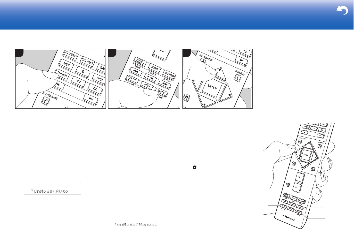
You can receive AM and FM radio stations
on this unit with the built-in tuner. Perform
the following procedure when the unit is on.
∫ Tuning into a Radio Station
Tuning Automatically
1. Press TUNER (a) on the remote
controller repeatedly to select either
"AM" or "FM" on the display.
2. Press MODE (e) on the remote
controller, so that the "TunMode: Auto" is
displayed on the display.
3. When you press the cursors /
buttons (b) on the remote controller,
automatic tuning starts, and searching
stops when a station is found. When
tuned into a radio station, the "TUNED"
indicator on the display lights. When
tuned into an FM stereo station, the
"STEREO" indicator lights.
When FM broadcasts reception is poor:
Perform the procedure for "Tuning
Manually" in the following section. Note
that if you tune manually, the reception for
FM broadcasts will be monaural rather than
stereo, irrespective of the sensitivity of the
reception.
Tuning Manually
Note that if you tune manually, the
reception for FM broadcasts will be
monaural rather than stereo, irrespective of
the sensitivity of the reception.
1. Press TUNER (a) on the remote
controller repeatedly to select either
"AM" or "FM" on the display.
2. Press MODE (e) on the remote
controller, so that the "TunMode:
Manual" is displayed on the display.
3. While pressing the cursors / (b) on
the remote controller, select the desired
radio station.
0 The frequency changes by 1 step
each time you press the cursors /
. The frequency changes
continuously if the button is held down
and stops when the button is
released.
Frequency step setting:
Press on the remote controller, and
from Home displayed select "System
Setup" - "Miscellaneous" - "Tuner" - "AM
Frequency Step", and select the frequency
step for your region. Note that when this
setting is changed, all radio presets are
deleted.
28
Page 29
> Before Start > Part Names > Install > Initial Setup >Playback > Advanced Manual
Troubleshooting | Supplementary Information, etc.
1 2 3
∫ Using RDS
En
RDS stands for Radio Data System and is
a method of transmitting data in FM radio
signals. In regions using RDS, the radio
station name is displayed when you tune
into a radio station broadcasting program
information. When you press on the
remote controller in this state, you can use
the following functions.
Display Text Information (Radio
Text)
1. While the name of the station is being
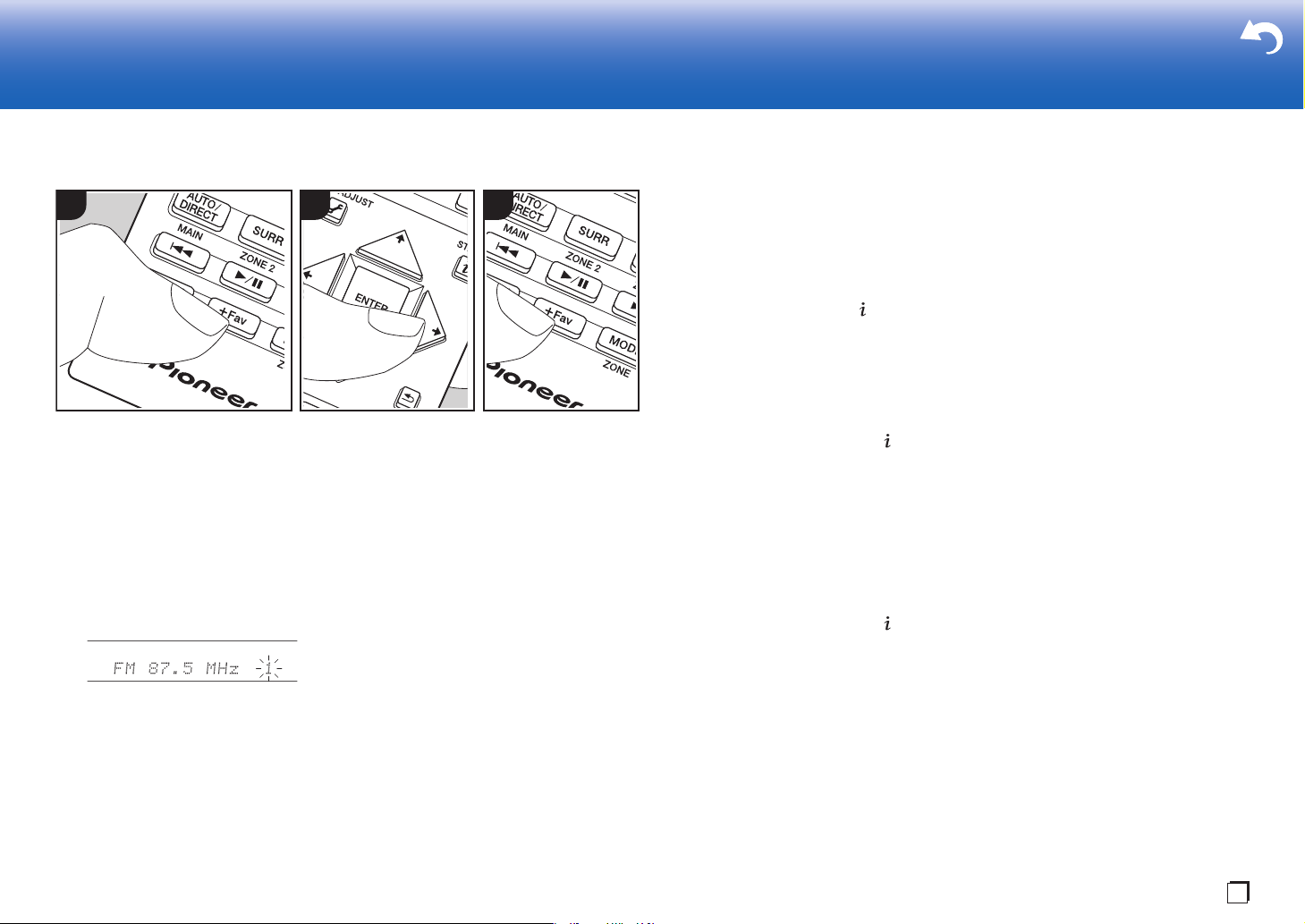
∫ Presetting a Radio Station
You can preset up to 40 stations.
Registration Procedure
After tuning into the AM/FM radio station
you want to register, perform the following
procedure.
1. Press +Fav (d) on the remote controller
so that the preset number on the display
flashes.
2. While the preset number is flashing
(about 8 seconds), repeatedly press the
cursors / (b) on the remote
controller to select a number between 1
and 40.
3. Press +Fav again on the remote
controller to register the station.
When registered, the preset number
stops flashing. Repeat this procedure for
all of your favorite AM/FM radio stations.
Selecting a Preset Radio Station
1. Press TUNER (a) on the remote
controller.
2. Press cursors / (b) on the remote
controller to select a preset number.
Deleting a Preset Radio Station
1. Press TUNER (a) on the remote
controller.
2. Press cursors / (b) on the remote
controller to select the preset number to
delete.
3. After pressing +Fav (d) on the remote
controller, press CLEAR (c) while the
preset number is flashing to delete the
preset number. When deleted, the
number on the display goes off.
displayed on the display, press on the
remote controller once.
Radio Text (RT) broadcast by the station
is displayed scrolling across the display.
"No Text Data" is displayed when no text
information is available.
Search for Stations by Program
Typ e
1. While the name of the station is being
displayed on the display, press on the
remote controller twice.
2. Press / on the remote controller to
select the Program Type you want to
find, then press ENTER to start the
search.
0 The Program Types displayed are as
follows: None / News (News reports) /
Affairs (Current affairs) / Info
(Information) / Sport / Educate
(Education) / Drama / Culture / Science
(Science and technology) / Varied / Pop
M (Pop music) / Rock M (Rock music) /
Easy M (Middle of the road music) / Light
M (Light classics) / Classics (Serious
classics) / Other M (Other music) /
Weather / Finance / Children (Children’s
programmes) / Social (Social affairs) /
Religion / Phone In / Travel / Leisure /
Jazz (Jazz music) / Country (Country
music) / Nation M (National music) /
Oldies (Oldies music) / Folk M (Folk
music) / Document (Documentary)
0 The information displayed may
sometimes not match the content being
broadcast by the station.
3. When a station is found, the station
flashes on the display. Press ENTER
while this is happening to start receiving
that station. If you don't press ENTER,
the unit continues to search for another
station.
0 If no stations are found, the message
"Not Found" is displayed.
0 Unusual characters may be displayed
when the unit receives unsupported
characters. However, this is not a
malfunction. Also, if the signal from a
station is weak, information may not be
displayed.
29
Page 30
Multi-zone
> Before Start > Part Names > Install > Initial Setup >Playback > Advanced Manual
Troubleshooting | Supplementary Information, etc.
1 2 3
c
d
e
a
b
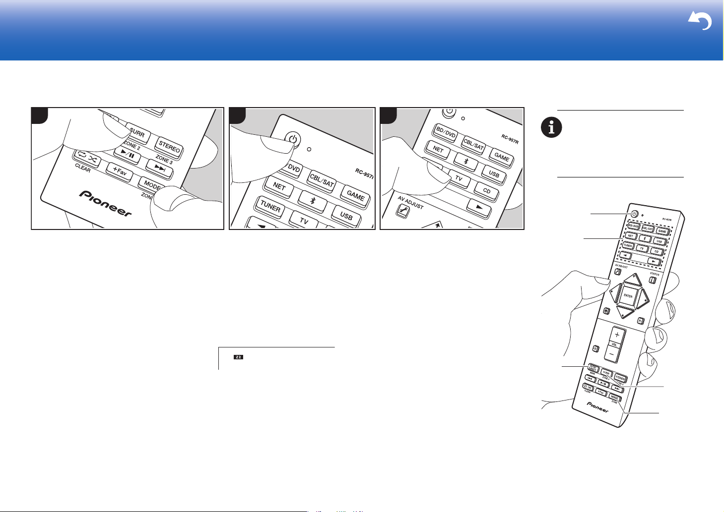
To return the remote controller
to main room control mode:
While holding down MODE on the
remote controller, press MAIN (c)
for 3 seconds or more until the
remote indicator flashes once.
Basic Operations
You can enjoy audio in the separate room
by, for example, playing a Blu-ray Disc
player in the main room (where this unit is
located) and listening to internet radio in
the separate room (ZONE 2).
0 DSD and Dolby TrueHD audio signals
are not output to ZONE 2 when selected
with the "NET" or "USB" input selector.
0 You can only select the same inputs for
the main room and separate room with
the "NET", "BLUETOOTH", or "USB"
input selector. If you have "NET"
selected in the main room and then
select "BLUETOOTH" in the separate
room, the main room also switches to
"BLUETOOTH". You cannot select
different stations for the main room and
separate room with the AM/FM radio.
0 If ZONE 2 is on, power consumption
during standby becomes larger than
normal.
Perform the following procedure when the
30
unit is on.
1. While holding down MODE (e) on the
remote controller, press ZONE 2 (d) for 3
or more seconds until the remote
indicator blinks twice.
0 The remote controller switches to the
mode for controlling ZONE 2.
2. Point the remote controller at the main
unit and press Í (a).
"Z2" lights on the main unit display.
3. Press the input selector button (b) of the
input to be played in the separate room.
0 On the main unit, after pressing ZONE
2-CONTROL, within 8 seconds turn
the input selector dial to select the
input to be played in the separate
room.
4. To adjust the volume on the power
amplifier in the separate room or the
ZONE speaker, adjust with VOL+/– on
the remote controller.
0 To control on the main unit, press
ZONE 2-CONTROL and adjust with
the MASTER VOLUME control within
8 seconds.
To turn off the function:
Press Í while in the mode for controlling
ZONE 2 on the remote controller.
Alternatively press ZONE 2-ON/OFF on the
main unit.
Playing in ZONE 2 only:
If you turn the unit to standby during multizone playback, the Z2 indicator is dimmed
and the playback mode is switched to
playback in a separate room only. Setting
ZONE 2 to on while this unit is in standby
will also switch the playback mode to the
same setting.
Page 31
Listening Mode
> Before Start > Part Names > Install > Initial Setup >Playback > Advanced Manual
Troubleshooting | Supplementary Information, etc.
a
b
c
d
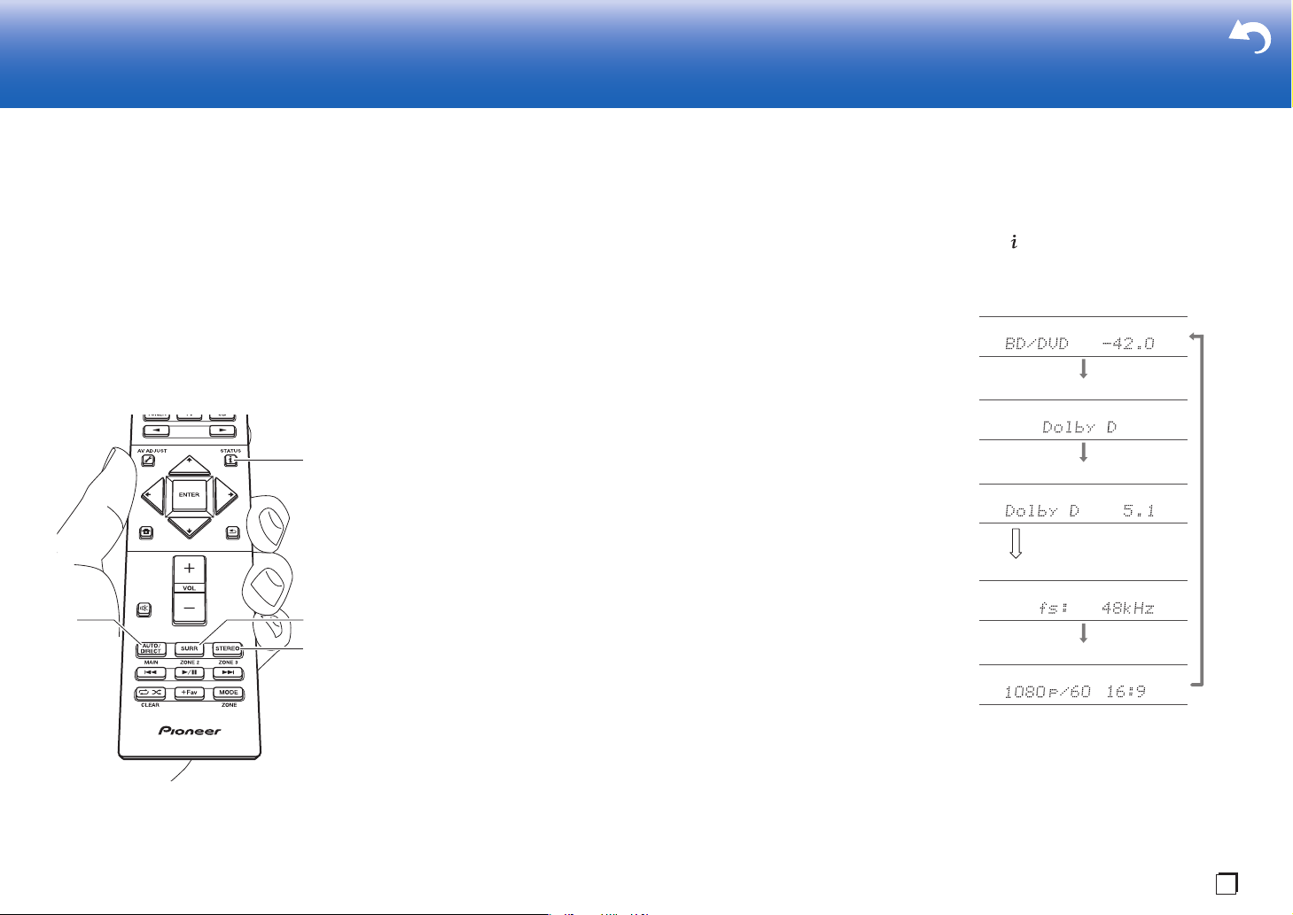
Input source & volume
Listening mode
Signal format
Sampling frequency
Input signal resolution
The display changes few
seconds later.
En
This unit is equipped with a variety of
listening modes. The basic operations are
introduced in the Basic Manual. For more
details, see the Advanced Manual.
0 The listening mode last selected for the
source is remembered for each of the
AUTO/DIRECT, SURR, and STEREO
buttons. If content you play is not
supported by the listening mode you
selected last, the listening mode that is
standard for that content is selected
automatically.
AUTO/DIRECT button (a)
Press repeatedly and the listening modes
suited to the input signal are switched
between "Auto Surround", "Direct", and
"Pure Direct". After selecting one of them,
"Auto Surround" (or "Direct" or "Pure
Direct") is displayed on the display of the
main unit, then the listening mode selected
automatically (Dolby Digital for multichannel input signals, Stereo for 2 channel
input signals, etc.) is displayed.
The "Direct" mode shuts down some
processing that can affect sound quality,
such as the tone control features, so you
can enjoy even better sound quality. The
"Pure Direct" mode shuts down even more
processes that affects sound quality, so
you get a more faithful reproduction of the
original sound. In this case, the speaker
calibration made with MCACC is disabled.
0 Depending on the input signal and
speaker configuration, the Dolby
Surround and DTS Neural:X modes that
expand 2 channel and 5.1 channel input
signals to 5.1 channel and 7.1 channel
may be automatically selected.
SURR button (c)
You can select a variety of listening modes
to suit your taste. There are the Dolby
Digital, DTS-HD Master Audio, and Stereo
modes that you can choose to suit the input
signal, or the Dolby Surround and DTS
Neural:X modes that can expand 2 channel
and 5.1 channel input signals to 5.1 or
7.1 channels. You can also enjoy original
surround modes such as Ext.Stereo and
Drama modes.
STEREO button (d)
You can select the "Stereo" mode to
playback only from the front speakers and
subwoofer.
Checking the Input Format and
Listening Mode
Press (b) on the remote controller
several times to switch the display of the
main unit as follows.
31
Page 32
License and Trademark
Manufactured under license from Dolby Laboratories. Dolby, Dolby Atmos,
Dolby Surround, Dolby Vision and the double-D symbol are trademarks of
Dolby Laboratories.
For DTS patents, see http://patents.dts.com. Manufactured under license from
DTS, Inc. DTS, the Symbol, DTS in combination with the Symbol, DTS:X, and
the DTS:X logo are registered trademarks or trademarks of DTS, Inc. in the
United States and/or other countries. © DTS, Inc. All Rights Reserved.
The BLUETOOTH® word mark and logos are registered trademarks owned by
Bluetooth SIG, Inc.
The Spotify software is subject to third party licenses found here:
https://developer.spotify.com/esdk-third-party-licenses/
This product is protected by certain intellectual property righ ts of Microsoft. Use
or distribution of such technology outside of this product is prohibited without a
license from Microsoft.
Windows 7, Windows Media, and the Windows logo are trademarks or
registered trademarks of Microsoft Corporation in the United States and/or
other countries.
DSD and the Direct Stream Digital logo are trademarks of Sony Corporation.
®
The terms HDMI and HDMI High-Definition Multimedia Interface, and the HDMI
Logo are trademarks or registered trademarks of HDMI Licensing LLC in the
United States and other countries.
The Wi-Fi CERTIFIED Logo is a certification mark of Wi-Fi Alliance®.
AirPlay, iPad, iPhone, iPod, iPod classic, iPod nano and iPod touch are
trademarks of Apple Inc., registered in the U.S. and other countries.
iPad Air and iPad mini are trademarks of Apple Inc.
“Made for iPod”, “Made for iPhone” and “Made for iPad” mean that an electronic
accessory has been designed to connect specifically to iPod, iPhone, or iPad,
respectively, and has been certi fied by the developer to meet A pple
performance standards. Apple is not responsible for the operation of this device
or its compliance with safety and regulatory standards.
Please note that the use of this accessory with iPod, iPhone or iPad may affect
wireless performance.
AirPlay works with iPhone, iPad, and iPod touch with iOS 4.3.3 or later, Mac
with OS X Mountain Lion or later, and PC with iTunes 10.2.2 or later.
PANDORA, the PANDORA logo, and the Pandora trade dress are trademarks
or registered trademarks of Pandora Media, Inc. Used with permission.
“All other trademarks are the property of their respective owners.”
“Toutes les autres marques commerciales sont la propriété de leurs détenteurs
respectifs.”
“El resto de marcas comerciales son propiedad de sus respectivos
propietarios”.
“Tutti gli altri marchi di fabbrica sono di proprietà dei rispettivi proprietari.”
“Alle anderen Warenzeichen sind das Eigentum ihrer jeweiligen Eigentümer.”
“Alle andere handelsmerken zijn eigendom van de desbetreffende
rechthebbenden.”
“Alla andra varumärken tillhör deras respektive ägare.”
32
Page 33
Register your product on
http://www.pioneer.eu
(Europe)
“Pioneer” is a trademark of Pioneer Corporation, and is used under license.
Printed in Malaysia / Imprimé en Malaisie
© 2017 Onkyo & Pioneer Corporation. All rights reserved.
© 2017 Onkyo & Pioneer Corporation. Tous droits de reproduction et de traduction réservés.
http://pioneer-audiovisual.com/privacy/
*29402813A*
F1711-1
SN 29402813A
<Germany>
Hanns-Martin-Schleyer-Straße 35, 47877 Willich, Germany
Tel: +49(0)8142 4208 188 (Product Support)
<UK>
Anteros Building, Odyssey Business Park, West End Road, South Ruislip,
Middlesex, HA4 6QQ United Kingdom
Tel: +44(0)208 836 3612
<France>
6, Avenue de Marais F - 95816 Argenteuil Cedex FRANCE
Tel: +33(0)969 368 050
1-10-5 Yokoami, Sumida-ku, Tokyo 130-0015 Japan
<U.S.A.>
18 PARK WAY, UPPER SADDLE RIVER, NEW JERSEY 07458, U.S.A.
Tel: 1-201-785-2600
Te l: 1-844-679-5350
 Loading...