

Page 1

AV Receiver
Operating Instructions
Discover the benefits of registering your product online at http://www.pioneer.co.uk (or http://www.pioneer.eu).
VSX-827
-K/-S
VSX-527
-K/-S
Page 2
IMPORTANT
VENTILATION CAUTION
The lightning flash with arrowhead symbol,
within an equilateral triangle, is intended to
alert the user to the presence of uninsulated
“dangerous voltage” within the product’s
enclosure that may be of sufficient
magnitude to constitute a risk of electric
shock to persons.
WARNING
This equipment is not waterproof. To prevent a fire or
shock hazard, do not place any container filled with
liquid near this equipment (such as a vase or flower
pot) or expose it to dripping, splashing, rain or
moisture.
WARNING
Before plugging in for the first time, read the following
section carefully.
The voltage of the available power supply differs
according to country or region. Be sure that the
power supply voltage of the area where this unit
will be used meets the required voltage (e.g., 230 V
or 120 V) written on the rear panel.
CAUTION
RISK OF ELECTRIC SHOCK
DO NOT OPEN
CAUTION:
TO PREVENT THE RISK OF ELECTRIC
SHOCK, DO NOT REMOVE COVER (OR
BACK). NO USER-SERVICEABLE PARTS
INSIDE. REFER SERVICING TO QUALIFIED
SERVICE PERSONNEL.
WARNING
To prevent a fire hazard, do not place any naked flame
sources (such as a lighted candle) on the equipment.
D3-4-2-1-3_A1_En
D3-4-2-1-4*_A1_En
Operating Environment
Operating environment temperature and humidity:
+5 °C to +35 °C (+41 °F to +95 °F); less than 85 %RH
(cooling vents not blocked)
Do not install this unit in a poorly ventilated area, or in
locations exposed to high humidity or direct sunlight (or
strong artificial light)
The exclamation point within an equilateral
triangle is intended to alert the user to the
presence of important operating and
maintenance (servicing) instructions in the
literature accompanying the appliance.
D3-4-2-1-1_A1_En
D3-4-2-1-7a_A1_En
D3-4-2-1-7c*_A1_En
This product is for general household purposes. Any
failure due to use for other than household purposes
(such as long-term use for business purposes in a
restaurant or use in a car or ship) and which requires
repair will be charged for even during the warranty
period.
K041_A1_En
When installing this unit, make sure to leave space
around the unit for ventilation to improve heat radiation
(at least 40 cm at top, 20 cm at rear, and 20 cm at each
side).
WARNING
Slots and openings in the cabinet are provided for
ventilation to ensure reliable operation of the product,
and to protect it from overheating. To prevent fire
hazard, the openings should never be blocked or
covered with items (such as newspapers, table-cloths,
curtains) or by operating the equipment on thick carpet
or a bed.
D3-4-2-1-7b*_A1_En
.
2
.
Page 3
Information for users on collection and disposal of old equipment and used batteries
Symbol for
equipment
Symbol examples
for batteries
Pb
These symbols on the products, packaging, and/or accompanying documents mean
that used electrical and electronic products and batteries should not be mixed with
general household waste.
For proper treatment, recovery and recycling of old products and used batteries,
please take them to applicable collection points in accordance with your national
legislation.
By disposing of these products and batteries correctly, you will help to save valuable
resources and prevent any potential negative effects on human health and the
environment which could otherwise arise from inappropriate waste handling.
For more information about collection and recycling of old products and batteries,
please contact your local municipality, your waste disposal service or the point of sale
where you purchased the items.
These symbols are only valid in the European Union.
For countries outside the European Union:
If you wish to discard these items, please contact your local authorities or dealer and
ask for the correct method of disposal.
K058a_A1_En
If the AC plug of this unit does not match the AC
outlet you want to use, the plug must be removed
and appropriate one fitted. Replacement and
mounting of an AC plug on the power supply cord of
this unit should be performed only by qualified
service personnel. If connected to an AC outlet, the
cut-off plug can cause severe electrical shock. Make
sure it is properly disposed of after removal.
The equipment should be disconnected by removing
the mains plug from the wall socket when left unused
for a long period of time (for example, when on
vacation).
D3-4-2-2-1a_A1_En
CAUTION
The STANDBY/ON switch on this unit will not
completely shut off all power from the AC outlet.
Since the power cord serves as the main disconnect
device for the unit, you will need to unplug it from the
AC outlet to shut down all power. Therefore, make
sure the unit has been installed so that the power
cord can be easily unplugged from the AC outlet in
case of an accident. To avoid fire hazard, the power
cord should also be unplugged from the AC outlet
when left unused for a long period of time (for
example, when on vacation).
D3-4-2-2-2a*_A1_En
3
Page 4

Contents
Thank you for buying this Pioneer product. Please read
through these operating instructions so you will know how to
operate your model properly.
Before you start
Checking what’s in the box. . . . . . . . . . . . . . . . . . . . . . . . . 6
Installing the receiver . . . . . . . . . . . . . . . . . . . . . . . . . . . . . 6
Flow of settings on the receiver
01 Controls and displays
Front panel . . . . . . . . . . . . . . . . . . . . . . . . . . . . . . . . . . . . . 7
Display . . . . . . . . . . . . . . . . . . . . . . . . . . . . . . . . . . . . . . 8
Remote control. . . . . . . . . . . . . . . . . . . . . . . . . . . . . . . . . . 9
Loading the batteries. . . . . . . . . . . . . . . . . . . . . . . . . . . 10
Operating range of remote control . . . . . . . . . . . . . . . . 10
02 Connecting your equipment
Determining the speakers’ application . . . . . . . . . . . . . . . 11
Some tips for improving sound quality . . . . . . . . . . . . . 11
Connecting the speakers . . . . . . . . . . . . . . . . . . . . . . . . . 12
Connect the surround back or front height speakers
(In case of VSX-827). . . . . . . . . . . . . . . . . . . . . . . . . . . . 12
Connect the surround back or front height speakers
(In case of VSX-527). . . . . . . . . . . . . . . . . . . . . . . . . . . . 12
Switching the speaker terminal . . . . . . . . . . . . . . . . . . . 14
Making cable connections . . . . . . . . . . . . . . . . . . . . . . . . 14
HDMI cables . . . . . . . . . . . . . . . . . . . . . . . . . . . . . . . . . 14
About HDMI . . . . . . . . . . . . . . . . . . . . . . . . . . . . . . . . . 14
Analog audio cables . . . . . . . . . . . . . . . . . . . . . . . . . . . 15
Digital audio cables. . . . . . . . . . . . . . . . . . . . . . . . . . . . 15
Video cables . . . . . . . . . . . . . . . . . . . . . . . . . . . . . . . . . 15
About the video converter (VSX-827 only) . . . . . . . . . . . . . 16
About video outputs connection
(VSX-527 only) . . . . . . . . . . . . . . . . . . . . . . . . . . . . . . . . . 16
Connecting a TV and playback components . . . . . . . . . . . 17
Connecting using HDMI . . . . . . . . . . . . . . . . . . . . . . . . 17
Connecting your TV with no HDMI input . . . . . . . . . . . . 18
Connecting your DVD player with no HDMI output
(VSX-827 only) . . . . . . . . . . . . . . . . . . . . . . . . . . . . . . . . 19
Connecting optional Bluetooth
Connecting to the network through LAN interface . . . . . . 20
Connecting antennas . . . . . . . . . . . . . . . . . . . . . . . . . . . . 21
Using external antennas . . . . . . . . . . . . . . . . . . . . . . . . 21
. . . . . . . . . . . . . . . . . . . . . . . . . . . . . 6
. . . . . . . . . . . . . . 6
®
ADAPTER . . . . . . . . . . . 20
Connecting a USB device . . . . . . . . . . . . . . . . . . . . . . . . . 21
Connecting an iPod . . . . . . . . . . . . . . . . . . . . . . . . . . . . . 22
Plugging in the receiver . . . . . . . . . . . . . . . . . . . . . . . . . . 22
03 Basic Setup
Canceling the Auto Power Down . . . . . . . . . . . . . . . . . . . 23
Canceling the demo display . . . . . . . . . . . . . . . . . . . . . . . 23
Automatically setting up for surround sound (MCACC) . . 23
Other problems when using the Auto MCACC setup. . . 24
04 Basic playback
Playing a source . . . . . . . . . . . . . . . . . . . . . . . . . . . . . . . . 25
Selecting the audio input signal . . . . . . . . . . . . . . . . . . 25
Playing an iPod . . . . . . . . . . . . . . . . . . . . . . . . . . . . . . . . . 27
Playing back files stored on an iPod . . . . . . . . . . . . . . . 27
Basic playback controls. . . . . . . . . . . . . . . . . . . . . . . . . 27
Watching photos and video content . . . . . . . . . . . . . . . 27
Playing a USB device . . . . . . . . . . . . . . . . . . . . . . . . . . . . 28
Playing back audio files stored on a USB memory
device . . . . . . . . . . . . . . . . . . . . . . . . . . . . . . . . . . . . . . 28
Playing back photo files stored on a USB memory
device . . . . . . . . . . . . . . . . . . . . . . . . . . . . . . . . . . . . . . 28
About playable file formats . . . . . . . . . . . . . . . . . . . . . . 29
Bluetooth® ADAPTER for Wireless Enjoyment of Music
Wireless music play. . . . . . . . . . . . . . . . . . . . . . . . . . . . 30
Pairing the Bluetooth ADAPTER and Bluetooth wireless
technology device . . . . . . . . . . . . . . . . . . . . . . . . . . . . . 30
Listening to Music Contents of Bluetooth wireless
technology device with Your System . . . . . . . . . . . . . . . 31
AIR JAM . . . . . . . . . . . . . . . . . . . . . . . . . . . . . . . . . . . . 31
Listening to the radio . . . . . . . . . . . . . . . . . . . . . . . . . . . . 32
Improving FM sound . . . . . . . . . . . . . . . . . . . . . . . . . . . 32
Saving station presets . . . . . . . . . . . . . . . . . . . . . . . . . . 32
Listening to station presets . . . . . . . . . . . . . . . . . . . . . . 32
Naming preset stations . . . . . . . . . . . . . . . . . . . . . . . . . 32
An introduction to RDS. . . . . . . . . . . . . . . . . . . . . . . . . . . 33
Searching for RDS programs. . . . . . . . . . . . . . . . . . . . . 33
Displaying RDS information . . . . . . . . . . . . . . . . . . . . . 33
. . . 30
05 Listening to your system
Choosing the listening mode . . . . . . . . . . . . . . . . . . . . . . 34
Auto playback . . . . . . . . . . . . . . . . . . . . . . . . . . . . . . . . 34
Listening in surround sound . . . . . . . . . . . . . . . . . . . . . 34
Using the Advanced surround . . . . . . . . . . . . . . . . . . . 35
Using Stream Direct . . . . . . . . . . . . . . . . . . . . . . . . . . . 35
Using the Sound Retriever . . . . . . . . . . . . . . . . . . . . . . . . 35
Listening with Acoustic Calibration EQ . . . . . . . . . . . . . . . 35
Better sound using Phase Control . . . . . . . . . . . . . . . . . . 36
Using surround back channel processing. . . . . . . . . . . . . 36
Setting the Up Mix function . . . . . . . . . . . . . . . . . . . . . . . 36
Setting the Audio options . . . . . . . . . . . . . . . . . . . . . . . . . 37
06 Playback with NETWORK features
Introduction . . . . . . . . . . . . . . . . . . . . . . . . . . . . . . . . . . . 39
About playable DLNA network devices. . . . . . . . . . . . . . 39
Using AirPlay on iPod touch, iPhone, iPad, and
iTunes . . . . . . . . . . . . . . . . . . . . . . . . . . . . . . . . . . . . . . 39
About the DHCP server function . . . . . . . . . . . . . . . . . . 39
Authorizing this receiver . . . . . . . . . . . . . . . . . . . . . . . . 39
Playback with Network functions . . . . . . . . . . . . . . . . . . . 40
Basic playback controls . . . . . . . . . . . . . . . . . . . . . . . . . 40
Listening to Internet radio stations. . . . . . . . . . . . . . . . . 40
Playing back audio files stored on components on
the network . . . . . . . . . . . . . . . . . . . . . . . . . . . . . . . . . . 41
Playing back your favorite songs . . . . . . . . . . . . . . . . . . 41
The Network Setup menu . . . . . . . . . . . . . . . . . . . . . . . . . 41
Network Configuration . . . . . . . . . . . . . . . . . . . . . . . . . . 42
Language. . . . . . . . . . . . . . . . . . . . . . . . . . . . . . . . . . . . 43
Firmware Update . . . . . . . . . . . . . . . . . . . . . . . . . . . . . . 43
Factory Reset . . . . . . . . . . . . . . . . . . . . . . . . . . . . . . . . . 43
System Information . . . . . . . . . . . . . . . . . . . . . . . . . . . . 43
About network playback . . . . . . . . . . . . . . . . . . . . . . . . . . 44
Content playable over a network . . . . . . . . . . . . . . . . . . 44
About playback behavior over a network . . . . . . . . . . . . 45
Glossary . . . . . . . . . . . . . . . . . . . . . . . . . . . . . . . . . . . . . . 45
About playable file formats . . . . . . . . . . . . . . . . . . . . . . . . 46
4
Page 5

Contents
07 Home Menu
Using the Home Menu . . . . . . . . . . . . . . . . . . . . . . . . . . . 47
Manual speaker setup . . . . . . . . . . . . . . . . . . . . . . . . . . . 47
Speaker Setting. . . . . . . . . . . . . . . . . . . . . . . . . . . . . . . 47
X.Over . . . . . . . . . . . . . . . . . . . . . . . . . . . . . . . . . . . . . . 48
Channel Level . . . . . . . . . . . . . . . . . . . . . . . . . . . . . . . . 49
Speaker Distance . . . . . . . . . . . . . . . . . . . . . . . . . . . . . 49
The Input Assign menu . . . . . . . . . . . . . . . . . . . . . . . . . . 50
Analog Input . . . . . . . . . . . . . . . . . . . . . . . . . . . . . . . . . 50
Component Input (VSX-827 only) . . . . . . . . . . . . . . . . . . 50
The Speaker System setting (VSX-827 only) . . . . . . . . . . . 50
The Video Parameter setting (VSX-827 only) . . . . . . . . . . . 50
Video Converter. . . . . . . . . . . . . . . . . . . . . . . . . . . . . . . 50
Resolution. . . . . . . . . . . . . . . . . . . . . . . . . . . . . . . . . . . 51
Aspect. . . . . . . . . . . . . . . . . . . . . . . . . . . . . . . . . . . . . . 51
The Pre Out Setting (VSX-527 only) . . . . . . . . . . . . . . . . . . 51
The Auto Power Down menu . . . . . . . . . . . . . . . . . . . . . . 52
The Network Standby menu . . . . . . . . . . . . . . . . . . . . . . . 52
The FL Demo Mode menu . . . . . . . . . . . . . . . . . . . . . . . . 52
08 Control with HDMI function
Making Control with HDMI connections. . . . . . . . . . . . . . 53
HDMI Setup . . . . . . . . . . . . . . . . . . . . . . . . . . . . . . . . . . . 53
Before using synchronization . . . . . . . . . . . . . . . . . . . . . . 54
About synchronized operations . . . . . . . . . . . . . . . . . . . . 54
Cautions on the Control with HDMI function . . . . . . . . . . 54
09 Controlling the rest of your system
Setting the remote to control other components . . . . . . . 55
Selecting preset codes directly. . . . . . . . . . . . . . . . . . . . . 55
Clearing all the remote control settings . . . . . . . . . . . . . . 55
Controls for TVs . . . . . . . . . . . . . . . . . . . . . . . . . . . . . . . . 56
Controls for other components. . . . . . . . . . . . . . . . . . . . . 56
Preset Code List . . . . . . . . . . . . . . . . . . . . . . . . . . . . . . . . 56
10 Additional information
Troubleshooting . . . . . . . . . . . . . . . . . . . . . . . . . . . . . . . . 62
General . . . . . . . . . . . . . . . . . . . . . . . . . . . . . . . . . . . . . 62
NETWORK feature . . . . . . . . . . . . . . . . . . . . . . . . . . . . . 63
HDMI. . . . . . . . . . . . . . . . . . . . . . . . . . . . . . . . . . . . . . . 64
Important information regarding the HDMI
connection . . . . . . . . . . . . . . . . . . . . . . . . . . . . . . . . . . 64
Windows 7 . . . . . . . . . . . . . . . . . . . . . . . . . . . . . . . . . . . . 65
About iPod/iPhone/iPad . . . . . . . . . . . . . . . . . . . . . . . . . . 65
About FLAC . . . . . . . . . . . . . . . . . . . . . . . . . . . . . . . . . . . 65
About messages displayed when using network
functions . . . . . . . . . . . . . . . . . . . . . . . . . . . . . . . . . . . . . 66
Resetting the main unit . . . . . . . . . . . . . . . . . . . . . . . . . . 66
Cleaning the unit . . . . . . . . . . . . . . . . . . . . . . . . . . . . . . . 66
Specifications . . . . . . . . . . . . . . . . . . . . . . . . . . . . . . . . . . 67
5
Page 6
Before you start
Flow of settings on the receiver
Checking what’s in the box
Please check that you’ve received the following supplied
accessories:
•
Setup microphone
•
Remote control
•
AAA size IEC R03 dry cell batteries (to confirm system
operation) x2
•
AM loop antenna
•
FM wire antenna
•
Power cord
•
iPod cable (VSX-827 only)
•
Warranty card
•
Quick start guide
•
Safety Brochure
•
These operating instructions (CD-ROM)
Installing the receiver
•
When installing this unit, make sure to put it on a level and
stable surface.
Don’t install it on the following places:
– on a color TV (the screen may distort)
– near a cassette deck (or close to a device that gives off a
magnetic field). This may interfere with the sound.
– in direct sunlight
– in damp or wet areas
– in extremely hot or cold areas
– in places where there is vibration or other movement
– in places that are very dusty
– in places that have hot fumes or oils (such as a kitchen)
The unit is a full-fledged AV receiver equipped with an
abundance of functions and terminals. It can be used easily
after following the procedure below to make the connections
and settings.
The colors of the steps indicate the following:
Required setting item
Setting to be made as necessary
- - - - - - - - - - - - - - - - - - - - - - - - - - - - - - - - - - - - - - - - - -
Connecting the speakers
1
Where you place the speakers will have a big effect on
the sound.
•
Determining the speakers’ application (page 11)
•
Connecting the speakers (page 12)
•
Switching the speaker terminal (page 14)
Connecting the components
2
For surround sound, you’ll want to hook up using a
digital connection from the Blu-ray Disc/DVD player to
the receiver.
•
About the video converter (VSX-827 only) (page 16)
•
About video outputs connection (VSX-527 only)
(page 16
)
•
Connecting a TV and playback components (page 17)
•
Connecting antennas (page 21)
•
Plugging in the receiver (page 22)
Power On
3
Make sure you’ve set the video input on your TV to this
receiver. Check the manual that came with the TV if you
don’t know how to do this.
The Speaker System setting (VSX-827 only) (page 50)
4
(Specify either using the surround back or front height
speaker.)
The Pre Out Setting (VSX-527 only) (page 51
(When connecting the front height speakers.)
The Input Assign menu (page 50
(When using connections other than the recommended
connections.)
HDMI Setup (page 53
(When the connected TV supports the HDMI Audio Return
Channel function.)
Use the on-screen automatic MCACC setup to set up
5
your system
•
Automatically setting up for surround sound (MCACC)
(page 23
)
Basic playback (page 25)
6
•
Selecting the audio input signal (page 25)
•
Playing an iPod (page 27)
•
Playing a USB device (page 28)
•
Choosing the listening mode (page 34)
Adjusting the sound as desired
7
•
Using the Sound Retriever (page 35)
•
Better sound using Phase Control (page 36)
•
Listening with Acoustic Calibration EQ (page 35)
•
Using surround back channel processing (page 36)
•
Setting the Up Mix function (page 36)
•
Setting the Audio options (page 37)
•
Manual speaker setup (page 47)
Making maximum use of the remote control
8
•
Setting the remote to control other components
(page 55
)
)
)
)
6
Page 7
Chapter
Controls and displays
1
1
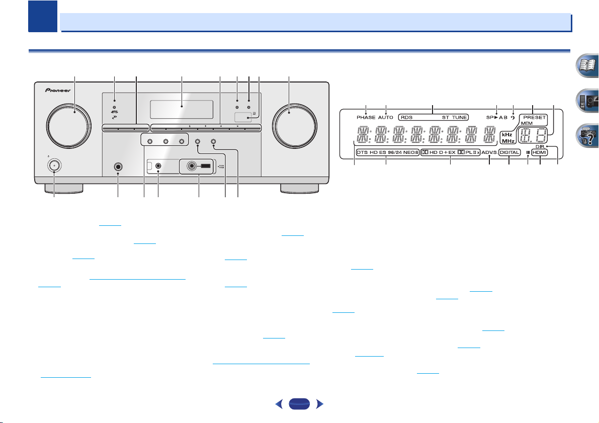
Front panel
1 7 938
2
456
SPEAKERS DIMMER DISPLAY BAND TUNER EDIT TUNE PRESET ENTER
INPUT
SELECTOR
STANDBY/ON
10
1
INPUT SELECTOR
Selects an input source (page 25).
2
MCACC indicator
Lights when Acoustic Calibration EQ (page 35) is on (Acoustic
Calibration EQ is automatically set to on after the Auto
MCACC setup (page 23
3
Receiver control buttons
SPEAKERS
page 14.
DIMMER
can be controlled in four steps.
DISPLAY
mode, sound volume, Speaker System (VSX-827)/Pre Out
(VSX-527) setting or input name can be checked by
selecting an input source.
• The Speaker System/Pre Out setting may or may not be
displayed, depending on the input source you have
selected.
4
Character display
See Display on page 8.
dial
)).
– See Switching the speaker terminal on
– Dims or brightens the display. The brightness
– Switches the display of this unit. The listening
PHONES
11 12
AUTO SURROUND
STREAM DIRECT
/
STANDARD SURR
ADVANCED
ALC/
RETRIEVER AIR
SURROUND
MCACC
VIDEO
SETUP
MIC
HDMIMCACC
iPod iPhone iPad
SOUND
iPod iPhone iPad
DIRECT CONTROL
USB
iPod
iPhone
iPad
MASTER
VOLUME
1513 14 16
5
Tuner control buttons
BAND
– Switches between AM, FM ST (stereo) and FM
MONO radio bands (page 32
TUNER EDIT
ENTER
(page 32
TUNE
PRESET
(page 32
6
HDMI indicator
Blinks when connecting an HDMI-equipped component;
lights when the component is connected (page 17
7
iPod iPhone iPad indicator
Lights when an iPod/iPhone/iPad is connected and
input is selected (page 27
8
Remote sensor
Receives the signals from the remote control (see Operating
range of remote control on page 10).
9
MASTER VOLUME
10
STANDBY/ON
– Use with
to memorize and name stations for recall
).
/
– Used to find radio frequencies (page 32).
/
– Use to select preset radio stations
).
dial
).
).
TUNE
/, PRESET
17 18 19 20 21 19
23
24 25 26 27 27 2928
11
PHONES jack
Use to connect headphones. When the headphones are
connected, there is no sound output from the speakers. The
/
).
iPod/USB
listening mode when the sound is heard from the headphone
and
can be selected only from PHONES SURR, STEREO or
STEREO ALC mode (S.R AIR mode can be also selected with
ADAPTER input).
12
Listening mode buttons
AUTO SURROUND/STREAM DIRECT
Auto surround mode (page 34
playback (page 35
ALC/STANDARD SURR
and to switch between the modes of 2 Pro Logic II, 2
Pro Logic IIx, 2 Pro Logic IIz and NEO:6, and the Auto
level control stereo mode (page 34
ADVANCED SURROUND
surround modes (page 35
13
MCACC SETUP MIC jack
Use to connect a microphone when performing Auto MCACC
setup (page 23
).
).
) and Stream Direct
– Press for standard decoding
).
– Switches between the various
).
22
– Switches between
7
Page 8
1
1
14
iPod iPhone iPad/USB terminal
Use to connect your Apple iPod or USB mass storage device
as an audio source (page 22
15
SOUND RETRIEVER AIR
When the button is pressed, the input switches to ADAPTER
and the listening mode is automatically set to S.R AIR
(page 31
).
16
iPod iPhone iPad DIRECT CONTROL
Change the receiver’s input to the iPod and enable iPod
operations on the iPod (page 28
).
).
Display
17
PHASE
Lights when the Phase Control is switched on (page 36).
18
AUTO
Lights when the Auto Surround feature is switched on
(page 34
).
19
Tuner indicators
RDS – Lights when an RDS broadcast is received
(page 33
).
ST – Lights when a stereo FM broadcast is being received
in auto stereo mode (page 32
TUNE – Lights when a normal broadcast channel.
PRESET – Shows when a preset radio station is registered
or called.
MEM – Blinks when a radio station is registered.
kHz/MHz – Lights when the character display is showing
the currently received AM/FM broadcast frequency.
20
Speaker indicators
Shows if the speaker system is on or not (page 14).
21
Sleep timer indicator
Lights when the receiver is in sleep mode (page 9).
22
PRESET information or input signal indicator
Shows the preset number of the tuner or the input signal type,
etc.
23
Character display
Displays various system information.
).
24
DTS indicators
DTS – Lights when a source with DTS encoded audio
signals is detected.
HD – Lights when a source with DTS-EXPRESS or DTS-HD
encoded audio signals is detected.
ES – Lights to indicate DTS-ES decoding.
96/24 – Lights when a source with DTS 96/24 encoded
audio signals is detected.
NEO:6 – When one of the NEO:6 modes of the receiver is
on, this lights to indicate NEO:6 processing (page 34
25
Dolby Digital indicators
2 D – Lights when a Dolby Digital encoded signal is
detected.
2 D+ – Lights when a source with Dolby Digital Plus
encoded audio signals is detected.
2HD – Lights when a source with Dolby TrueHD encoded
audio signals is detected.
).
EX – Lights to indicate Dolby Digital EX decoding.
2PLII(x) – Lights to indicate 2 Pro Logic II/2 Pro Logic
IIx decoding. Light will go off during 2 Pro Logic IIz
decoding (see Listening in surround sound
more on this).
26
ADV.S.
Lights when one of the Advanced Surround modes has been
selected (see Using the Advanced surround
more on this).
27
SIGNAL SELECT indicators
DIGITAL – Lights when a digital audio signal is selected.
Blinks when a digital audio signal is selected and selected
audio input is not provided.
HDMI – Lights when an HDMI signal is selected. Blinks
when an HDMI signal is selected and selected HDMI input
is not provided.
28
Up Mix/DIMMER indicator
Lights when the Up Mix function is set to ON (page 36). Also,
lights when DIMMER is set to off.
29
DIR.
Lights when the DIRECT or PURE DIRECT mode is switched
on (page 35
).
on page 34 for
on page 35 for
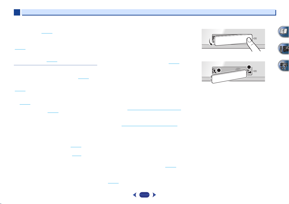
Removing the front cover
MCACC
SETUP
MIC
Attaching the front cover
MCACC
2
SETUP
MIC
Controls and displays
5 V
2.1
VIDEO
VIDEO
A
iPod
iPhone
USB
iPad
1
USB
iPod
iPhone
iPad
8
Page 9
SLEEP
INPUT
1
4
7
RECEIVER
ENTER
2
5
8
DISP
CLR
3
6
9
0
ENTER
CH
CH
MUTE
RETURN
AUDIO
PARAMETER
MENU
HOME
MENU
RECEIVER
RECEIVER
SOURCE
TOOLS
BAND
iPod CTRL
PTY
TOP
MENU
T
U
N
E
T
U
N
E
P
R
E
S
E
T
P
R
E
S
E
T
SHIFT
1
2
11
12
13
14
15
16
3
4
5
6
7
8
9
10
RECEIVER
1
1
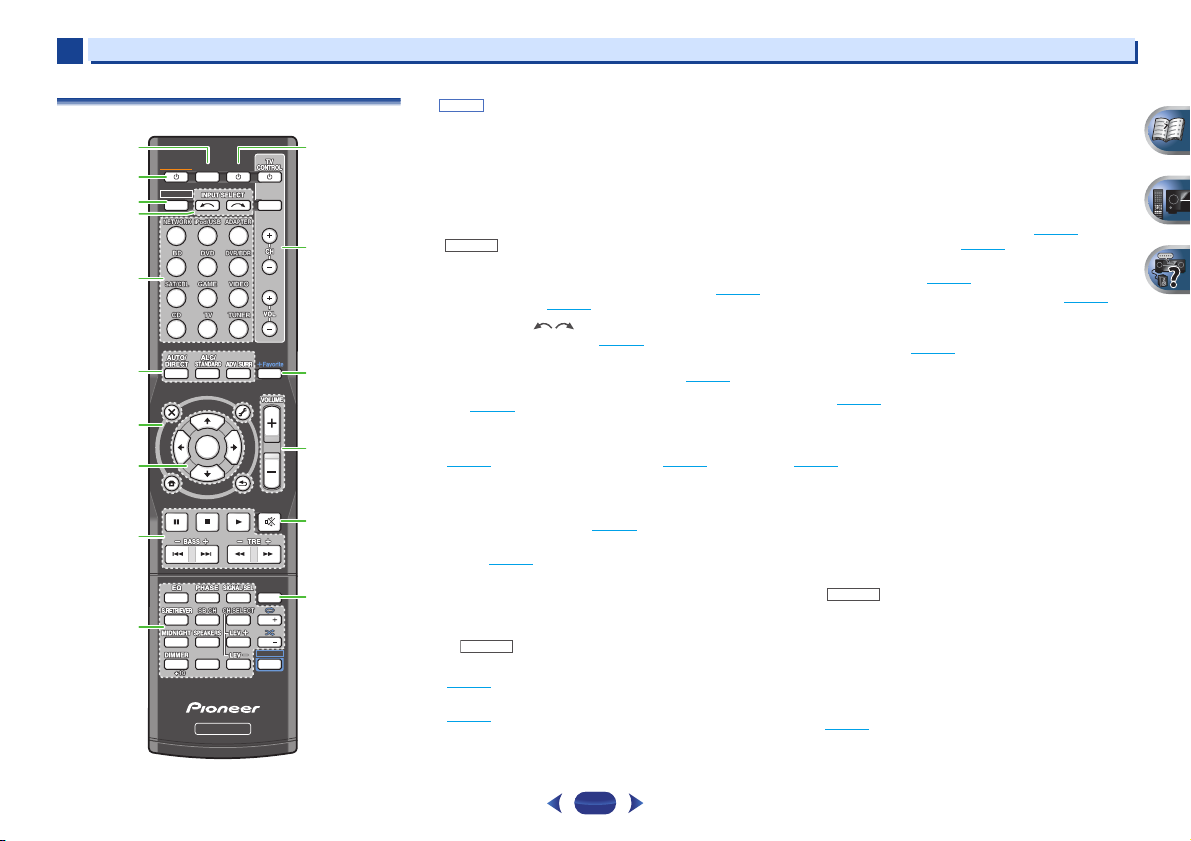
Remote control
•
button is not used with this receiver.
SHIFT
1
SLEEP
Press to change the amount of time before the receiver
switches into standby (30 min – 60 min – 90 min – Off). You
can check the remaining sleep time at any time by pressing
SLEEP
once.
2
RECEIVER
Switches the receiver between standby and on.
3
RECEIVER
Switches the remote to control the receiver (used to select the
white commands above the number buttons (
etc)). Also use this button to set up surround sound (page 47
or Audio parameters (page 37
4
INPUT SELECT
Use to select the input source (page 25).
5
Input function buttons
Use to select the input source to this receiver (page 25). This
will enable you to control other components with the remote
control (page 55
6
Listening mode buttons
AUTO/DIRECT
(page 34
ALC/STANDARD SURR
and to switch between the modes of 2 Pro Logic II, 2
Pro Logic IIx, 2 Pro Logic IIz and NEO:6, and the Auto
level control stereo mode (page 34
ADV SURR
modes (page 35
7
Receiver and component control buttons
The following button controls can be accessed after you have
selected the corresponding input function button (
etc.).
).
– Switches between Auto surround mode
) and Stream Direct playback (page 35).
– Switches between the various surround
).
– Press for standard decoding
).
).
MIDNIGHT
BD, DVD
,
Press first to access:
AUDIO PARAMETER
(page 37
).
HOME MENU
(page 47
).
RETURN
– Confirm and exit the current menu screen.
– Use to access the Audio options
– Press to access the Home Menu
Controls and displays
BD, DVD
or
DVR/BDR
Press
TOP MENU
Disc/DVD.
HOME MENU
RETURN
MENU
Press
TOOLS
used to change the name (page 32
BAND
MONO radio bands (page 32
)
PTY
Press
iPod CTRL
receiver controls (page 27
8
/// (TUNE
Use the arrow buttons when setting up your surround sound
system (page 47
menus/options.
Use
TUNE
PRESET
(page 32
9
Component control buttons
The main buttons (, , etc.) are used to control a component
after you have selected it using the input function buttons.
The controls above these buttons can be accessed after you
have selected the corresponding input function button (
DVD
below.
Press first to access:
,
BASS +/–, TRE +/–
• These controls are disabled when the listening mode is
• When the front speaker is set at SMALL in the Speaker
– Displays the disc ‘top’ menu of a Blu-ray
– Displays the HOME MENU screen.
– Confirm and exit the current menu screen.
– Display s the TOOLS menu of Blu-ray Disc player.
TUNER
first to access:
– Memorizes stations for recall (page 32), also
– Switches between AM, FM ST (stereo) and FM
– Use to search for RDS program types (page 33).
iPod/USB
first to access:
– Switches between the iPod controls and the
). Also used to control Blu-ray Disc/DVD
/
can be used to find radio frequencies and
/
can be used to select preset radio stations
).
and CD). These buttons also function as described
RECEIVER
set to DIRECT or PURE DIRECT.
Setting (or automatically via the Auto MCACC setup)
and the X.Over is set above 150 Hz, the subwoofer
channel level will be adjusted by pressing
(page 48
).
first to access:
).
).
).
/, PRESET
/
),
ENTER
– Use to adjust Bass or Treble.
BASS +/–
BD
,
9
Page 10
1
CAUTION
30°
7 m
30°
1
10
Number buttons and other component controls
Use the number buttons to directly select a radio frequency
(page 32
) or the tracks on a CD, etc. There are other buttons
that can be accessed after is pressed. (For example
MIDNIGHT
11
Press to turn on/off other components connected to the
receiver (page 55
12
These buttons are dedicated to control the TV assigned to the
TV
system assign it to the
13
Press while a song is being played back or stopped. The
selected song is then registered in the Favorites folder
(page 41
14
Use to set the listening volume.
, etc.)
EQ
– Press to switch on/off Acoustic Calibration EQ
setting (page 35
PHASE
– Press to switch on/off Phase Control (page 36).
SIGNAL SEL
component to play back (page 25
S.RETRIEVER
compressed audio sources (page 35
SB CH
back channel (page 36
CH SELECT
use
LEV +/–
MIDNIGHT
(page 37
SPEAKERS
page 14.
DIMMER
can be controlled in four steps.
SOURCE
TV CONTROL buttons
button. Thus if you only have one TV to hook up to this
– Use to turn on/off the power of the TV.
INPUT
CH +/–
VOL +/–
+Favorite
VOLUME +/–
– Press to select the audio input signal of the
– Press to select ON, AUTO or OFF the surround
– Press repeatedly to select a channel, then
LEV +/–
to adjust the level (page 49).
– Use to adjust the channel level.
– Switches to Midnight or Loudness listening
).
– See Switching the speaker terminal on
– Dims or brightens the display. The brightness
– Use to select the TV input signal.
– Use to select channels.
– Use to adjust the volume on your TV.
).
RECEIVER
).
– Press to restore CD quality sound to
).
TV
button (page 56).
).
).
).
15
MUTE
Mutes/unmutes the sound.
16
DISP
Switches the display of this unit. The listening mode, sound
volume, Speaker System (VSX-827)/Pre Out (VSX-527) setting or
input name can be checked by selecting an input source.
•
The Speaker System/Pre Out setting may or may not be
displayed, depending on the input source you have
selected.
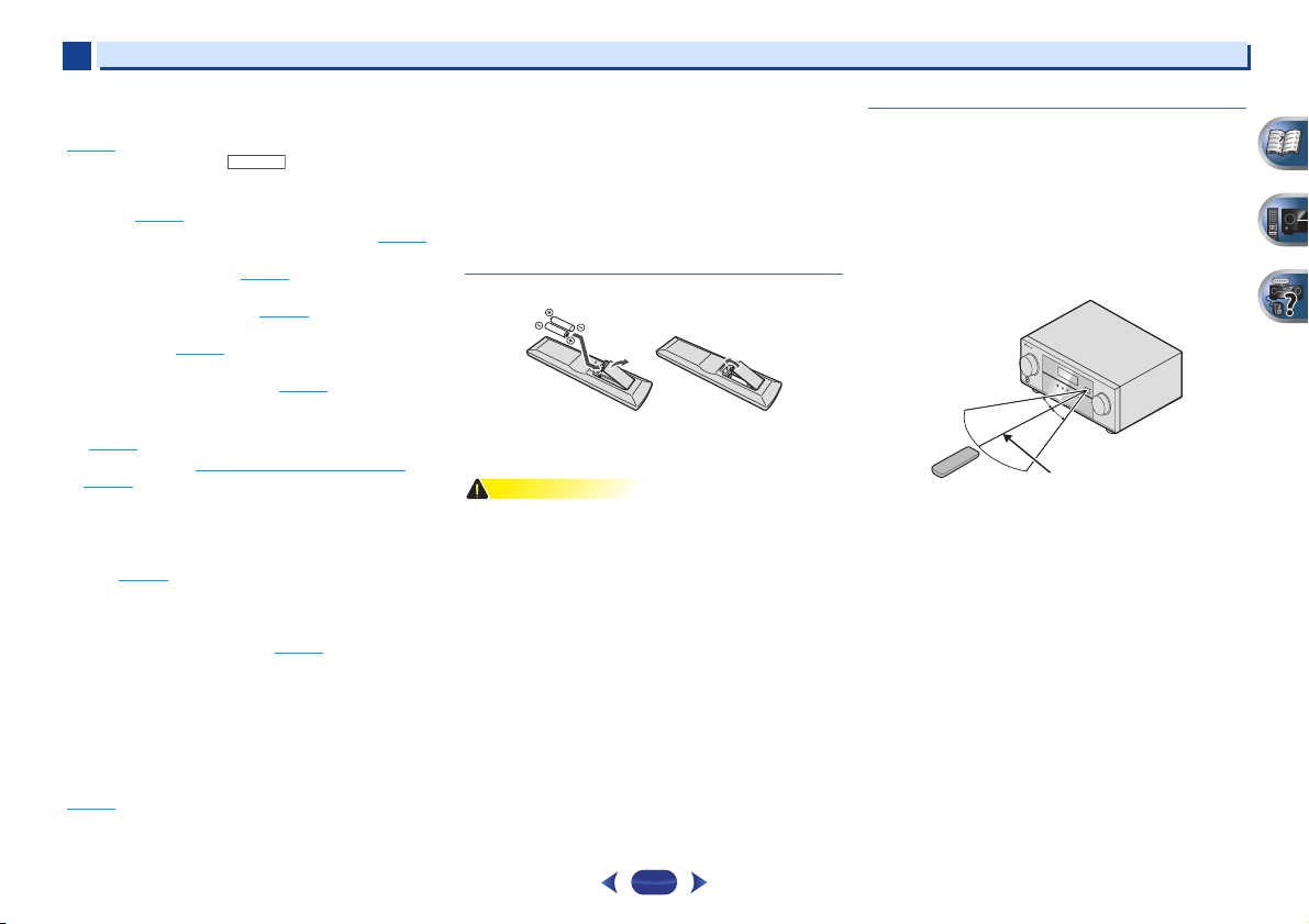
Loading the batteries
The batteries included with the unit are to check initial
operations; they may not last over a long period. We
recommend using alkaline batteries that have a longer life.
•
Incorrect use of batteries may result in such hazards as
leakage and bursting. Observe the following precautions:
-
Never use new and old batteries together.
-
Insert the plus and minus sides of the batteries properly
according to the marks in the battery case.
-
Batteries with the same shape may have different
voltages. Do not use different batteries together.
-
When disposing of used batteries, please comply with
governmental regulations or environmental public
instruction’s rules that apply in your country or area.
-
Do not use or store batteries in direct sunlight or other
excessively hot place, such as inside a car or near a
heater. This can cause batteries to leak, overheat,
explode or catch fire. It can also reduce the life or
performance of batteries.
Controls and displays
Operating range of remote control
The remote control may not work properly if:
•
There are obstacles between the remote control and the
receiver’s remote sensor.
•
Direct sunlight or fluorescent light is shining onto the
remote sensor.
•
The receiver is located near a device that is emitting
infrared rays.
•
The receiver is operated simultaneously with another
infrared remote control unit.
10
Page 11
Chapter
Important
5.1 channel surround
system:
6.1 channel surround
(Surround back) system:
7.1 channel surround
(Surround back) system:
7.1 channel surround
(Front height) system:
Main zone
Speaker B
2
2
Connecting your equipment
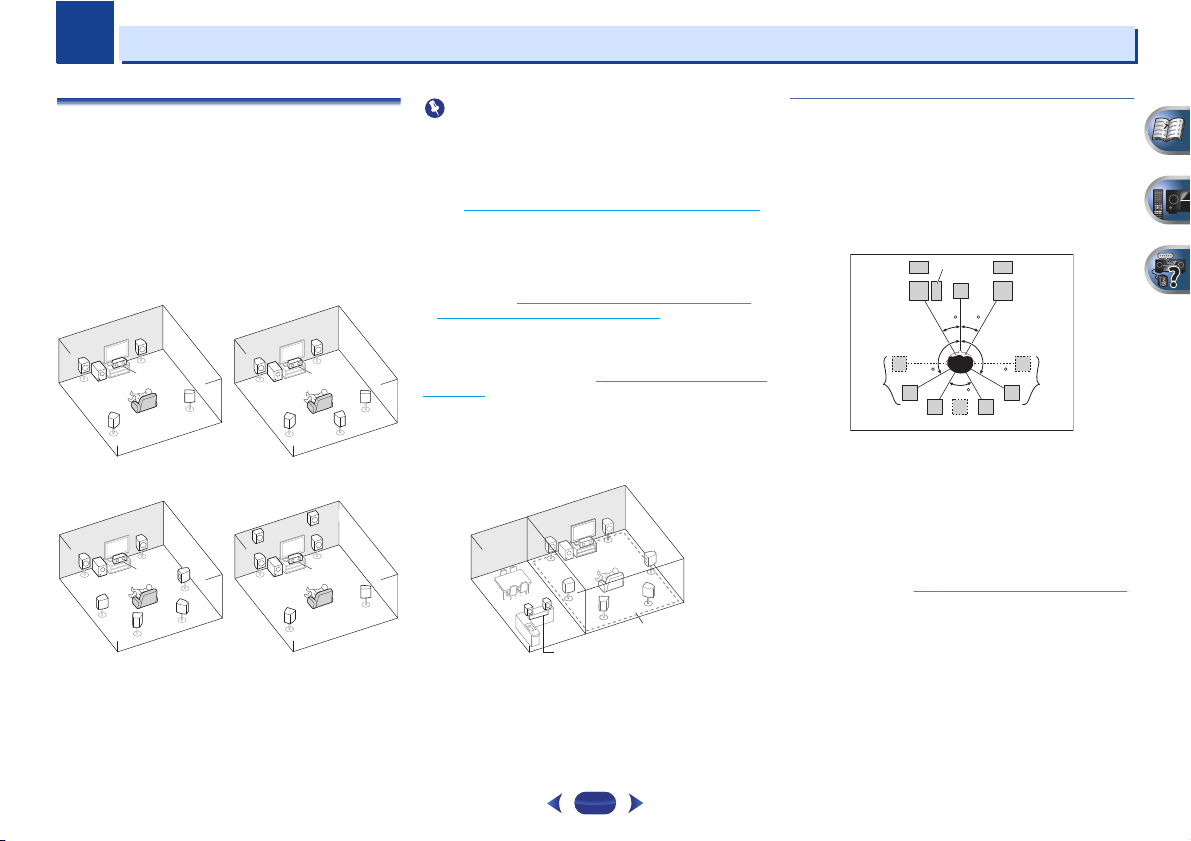
Determining the speakers’ application
By connecting the left and right front speakers (L/R), the
center speaker (C), the left and right surround speakers (SL/
SR), the left and right surround back speakers (SBL/SBR) (or
the left and right front height speakers (FHL/FHR)), and the
subwoofer (SW), a surround sound system up to 7.1 channel
can be enjoyed.
The 5.1 channel surround system is the most commonly-used
in home theaters. To achieve the best possible surround
sound, install your speakers as shown below.
RR
L
SW
SL
L
SW
SL
SBL
C
SR
R
C
SR
SBR
L
SW
FHL
L
SW
Some tips for improving sound quality
•
VSX-827 only: Both the surround back speakers and the
front height speakers can be connected at the same time.
In this case, sound will be output from either the front
height speaker or the surround back speaker depending on
which one was selected in the Speaker System setting
(see The Speaker System setting (VSX-827 only)
•
VSX-527 only: To connect the surround back or front
height speakers, an additional amplifier is required.
Connect the additional amplifier to the PRE OUT SURR
BACK/FRONT HEIGHT outputs of this unit and connect the
surround back or front height speakers to the additional
amplifier (see Connect the surround back or front height
speakers (In case of VSX-527) on page 12).
VSX-827 only: Another way, you can use the speakers
C
SR
SB
SL
FHR
R
C
SL
SR
connected to the B speaker terminals to listen to stereo
playback in another room. See Switching the speaker terminal
on page 14 for the listening options with this setup.
•
You will not be able to connect the B speakers if you
connect the front height speakers in the main zone.
Further, if you use the B speakers, a 5.1 ch playback will be
the maximum in the main zone. (No sound is output from
the surround back speaker.)
R
L
on page 50).
Where you put your speakers in the room has a big effect on
the quality of the sound. The following guidelines should help
you to get the best sound from your system.
•
It is best to angle the speakers towards the listening
position. The angle depends on the size of the room. Use
less of an angle for bigger rooms.
•
Refer to the chart below for placement of speakers you
intend to connect.
SW
FHL
L
30 30
-
Place the surround speakers at 120º from the center. If
you, (1) use the surround back speaker, and, (2) don’t use
the front height speakers, we recommend placing the
surround speaker right beside you.
-
If you intend to connect only one surround back
speakers, place it directly behind you.
-
If the surround speakers cannot be set directly to the side
of the listening position with a 7.1-channel system, the
surround effect can be enhanced by turning off the Up
Mix function (see Setting the Up Mix function
•
For the best stereo effect, place the front speakers 2 m to
3 m apart, at equal distance from the TV.
•
If you’re using a center speaker, place the front speakers at
a wider angle. If not, place them at a narrower angle.
•
Place the center speaker above or below the TV so that the
sound of the center channel is localized at the TV screen.
Also, make sure the center speaker does not cross the line
formed by the leading edge of the front left and right
speakers.
SL
120 120
60
SBL
SB
FHR
C
R
SR
SBR
on page 36).
11
Page 12
2
CAUTION
CAUTION
10 mm
10 mm
2
•
Surround and surround back speakers should be
positioned 60 cm to 90 cm higher than your ears and titled
slight downward. Make sure the speakers don’t face each
other. For DVD-Audio, the speakers should be more directly
behind the listener than for home theater playback.
•
Try not to place the surround speakers farther away from
the listening position than the front and center speakers.
Doing so can weaken the surround sound effect.
•
Place the left and right front height speakers at least one
meter directly above the left and right front speakers.
•
If you’re going to place speakers around your CRT TV, use
shielded speakers or place the speakers at a sufficient
distance from your CRT TV.
•
The subwoofer can be placed on the floor. Ideally, the other
speakers should be at about ear-level when you’re listening
to them. Putting the speakers on the floor (except the
subwoofer), or mounting them very high on a wall is not
recommended.
•
When not connecting a subwoofer, connect speakers with
low frequency reproduction capabilities to the front
channel. (The subwoofer’s low frequency component is
played from the front speakers, so the speakers could be
damaged.)
•
After connecting, be sure to conduct the Auto MCACC
(speaker environment setting) procedure.
See Automatically setting up for surround sound (MCACC)
on page 23.
•
Make sure that all speakers are securely installed. This not
only improves sound quality, but also reduces the risk of
damage or injury resulting from speakers being knocked
over or falling in the event of external shocks such as
earthquakes.
Connecting the speakers
The receiver will work with just two stereo speakers (the front
speakers in the diagram) but using at least three speakers is
recommended, and a complete setup is best for surround
sound.
Make sure you connect the speaker on the right to the right (R)
terminal and the speaker on the left to the left (L) terminal.
Also make sure the positive and negative (+/–) terminals on
the receiver match those on the speakers.
You can use speakers with a nominal impedance between 6 Ω
and 16 Ω.
Be sure to complete all connections before connecting this unit
to the AC power source.
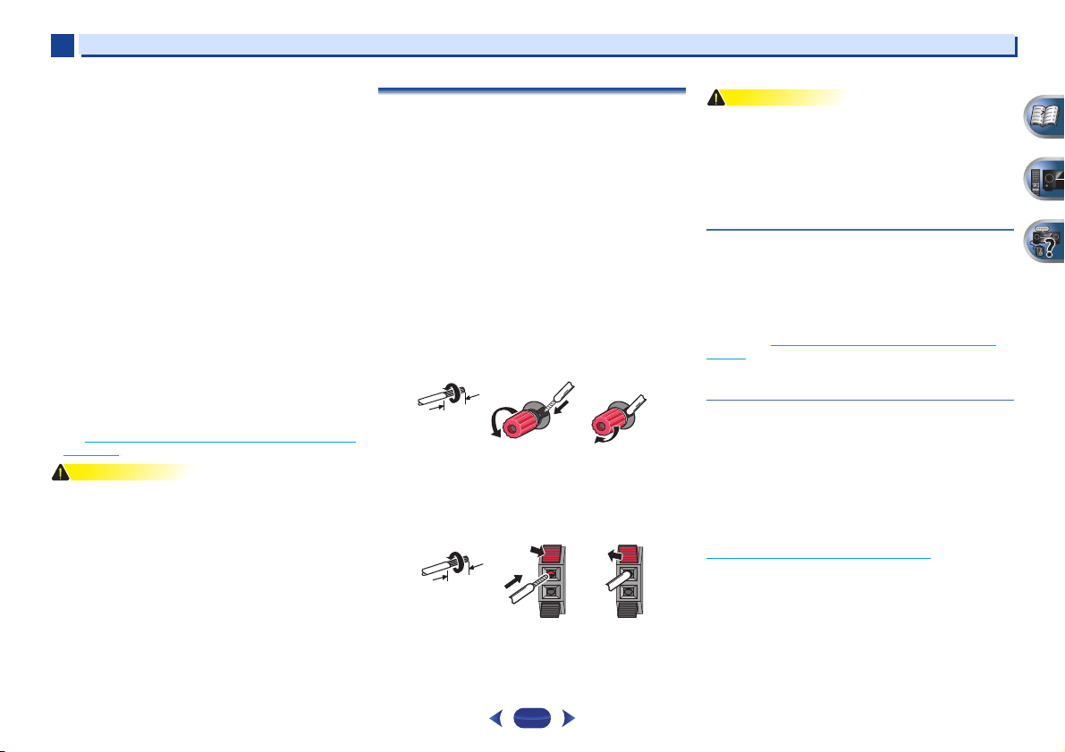
Bare wire connections
1
Twist exposed wire strands together.
2
Loosen terminal and insert exposed wire.
3
Tighten terminal.
12 3
Connect the wires to the B-Speakers terminals of the VSX-827 as
shown below:
1
Twist exposed wire strands together.
2
Push open the tabs and insert exposed wire.
3
Release the tabs.
12 3
Connecting your equipment
•
These speaker terminals carry HAZARDOUS LIVE voltage.
To prevent the risk of electric shock when connecting or
disconnecting the speaker cables, disconnect the power
cord before touching any uninsulated parts.
•
Make sure that all the bare speaker wire is twisted together
and inserted fully into the speaker terminal. If any of the
bare speaker wire touches the back panel it may cause the
power to cut off as a safety measure.
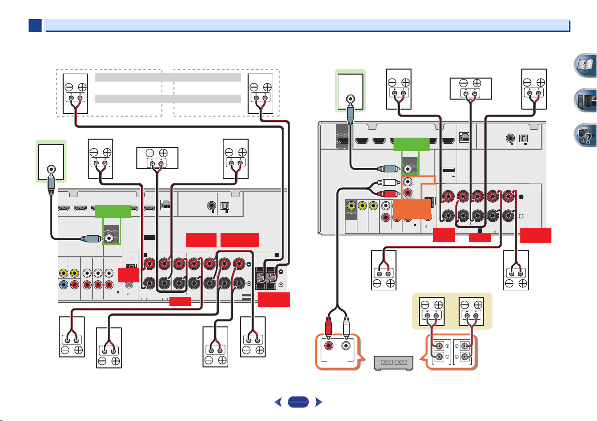
Connect the surround back or front height
speakers (In case of VSX-827)
The Speaker System setting must be set if the above
connections are performed. Select Surr.Back if the surround
back speaker is connected and Height if the front height
speaker is connected (If neither the surround back speaker
nor the front height speaker is connected, either setting will
suffice) (see The Speaker System setting (VSX-827 only)
page 50).
•
When using only one surround back speaker, connect it to
the SURROUND BACK L (Single) terminals.
on
Connect the surround back or front height
speakers (In case of VSX-527)
Connect the PRE OUT SURR BACK/FRONT HEIGHT outputs
of the unit and additional amplifier to add a surround back or
front height speaker.
The Pre Out setting must be set if the above connections are
performed. Select Surr.Back if the surround back speaker is
connected and Height if the front height speaker is
connected (If neither the surround back speaker nor the front
height speaker is connected, either setting will suffice) (see
The Pre Out Setting (VSX-527 only)
•
You can use the additional amplifier on the surround back
channel pre-outs for a single speaker as well. In this case
plug the amplifier into the left (L (Single)) terminal only.
on page 51).
12
Page 13
2
Front height setting
Speaker B setting
Front right
Subwoofer
Center
Front left
Surround right
Surround left
Surround
back right
Surround
back left
Front height right
Speaker B - right
Front height left
Speaker B - left
The front height terminals can also be used for Speaker B.
When using only one surround back speaker, connect it
to the SURROUND BACK L (Single) terminals.
Center
Surround right
Front right
Front left
Subwoofer
Surround left
Right
Surround back or
front height speakers
Surround back or front height
channel amplifier
Left
2
VSX-827 connection diagram VSX-527 connection diagram
LINE LEVEL
HDMI
OUT
INPUT
MONITOR
OUT
ADAPTER PORT
(
OUTPUT 5 V
0.1 A MAX
A
RL
CAUTION:
SPEAKER IMPEDANCE
6 -16 .
LAN
)
FRONT
ATTENTION:
ENCEINTE D’IMPEDANCE DE
6 -16 .
LINE LEVEL
INPUT
DVD GAME VIDEOBD
IN
PB PR
NENT VIDEO
PREOUT
SAT/CBL DVR/BDR
SUBWOOFER
AUDIO
DVD INSAT/CBL
DVD
SAT/CBL
IN
PRE OUT
SUB WOOFER
ANTENNA
AM LOOP
FRONT
L
IN
R L
R
FM UNBAL
1
1
ANALOG IN
75
(CD)
ASSIGNABLE
(10/100
CENTER
CENTER
)
COAXIAL
ASSIGNABLE
IN1IN
(CD)
SURROUND
R L
SURROUND
RL
SPEAKERS
OPTICAL
ASSIGNABLE
1
(TV)
SURROUND BACK
R L
SURROUND BACK FRONT HEIGHT /
(
)
Single
RL
SELECTABLE
SEE INSTRUCTION MANUAL
FRONT HEIGHT
VOIR LE MODE D’EMPLOI
SELECTABLE
RL
B
R L
DVD GAME VIDEOBD
IN
PREOUT
SAT/CBL DVR/BDR
SUBWOOFER
PREOUT
SURR BACK/
DVD INSAT/CBL
FRONT HEIGHT
DVD
SAT/CBL
VIDEO
IN
PRE OUT
SUB WOOFER
PRE OUT
ANALOG IN
ASSIGNABLE
AUDIO
SURR BACK/
FRONT HEIGHT
L
(
)
Single
R
L
IN
R
(CD)
1
1
ANTENNA
AM LOOP
FM UNBAL
75
Connecting your equipment
(
)
CENTER
A
CENTER
COAXIAL
ASSIGNABLE
SURROUND
RL
CAUTION:
SPEAKER IMPEDANCE
6 -16 .
ADAPTER PORT
(
OUTPUT 5 V
0.1 A MAX
Class 2 Wiring
FRONT
R L
LAN
10/100
)
FRONT
RL
SPEAKERS
IN1IN
(TV)
(CD)
ATTENTION:
ENCEINTE D’IMPEDANCE DE
6 -16 .
OPTICAL
ASSIGNABLE
1
SURROUND
R L
13
RL
ANALOG
AUDIO IN
SPEAKER R SPEAKER L
Page 14
2
Note
Important
Note
2
Switching the speaker terminal
Use
SPEAKERS
off. When the SP OFF is selected, no sound is output from the
speakers connected to this receiver.
VSX-827 only: If you selected Surr.Back in The Speaker System
setting (VSX-827 only) on page 50, you can switch between
speakers using the
the button will simply switch your main speaker terminal on or
off. The options below are for the Surr.Back setting only.
Use the
speaker terminal setting.
Press repeatedly to choose a speaker terminal option:
•
SPA – Sound is output from the speakers connected to
the A-speaker terminals and PRE OUT SURR BACK/FRONT
HEIGHT (VSX-527 only) (multichannel playback is possible).
•
SPB (VSX-827 only) – Sound is output from the two
speakers connected to the B-speaker terminals (only stereo
playback is possible).
•
SPAB (VSX-827 only) – Sound is output from the Aspeaker terminals, the two speakers in the B-speaker
terminals, and the subwoofer. Multichannel sources are
downmixed only when the STEREO or STEREO ALC mode
is selected for stereo output from A- and B-speaker
terminals.
•
SP – No sound is output from the speakers.
•
VSX-827 only: The subwoofer output depends on the
settings you made in Speaker Setting
if SPB is selected above, no sound is heard from the
subwoofer (the LFE channel is not downmixed).
•
All speaker terminals are switched off (SP) when
headphones are connected. SPB can be selected even
when headphones are connected for VSX-827.
button to change the speaker system on or
SPEAKERS
SPEAKERS
SPEAKERS DIMMER DISPLAY
button. If you selected Height,
button on the front panel to select a
on page 47. However,
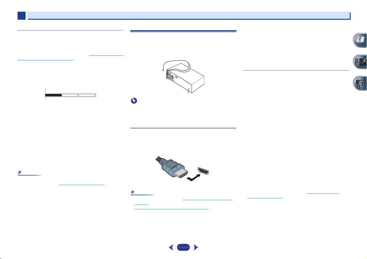
Making cable connections
Make sure not to bend the cables over the top of this unit (as
shown in the illustration). If this happens, the magnetic field
produced by the transformers in this unit may cause a
humming noise from the speakers.
•
Before making or changing connections, switch off the
power and disconnect the power cord from the AC outlet.
•
Before unplugging the power cord, switch the power into
standby.
HDMI cables
Both video and sound signals can be transmitted
simultaneously with one cable. If connecting the player and
the TV via this receiver, for both connections, use HDMI
cables.
HDMI
Be careful to connect the terminal in the proper direction.
•
Set the HDMI parameter in Setting the Audio options on
page 37 to THRU (THROUGH) and set the input signal in
Selecting the audio input signal
want to hear HDMI audio output from your TV (no sound
will be heard from this receiver).
on page 25 to HDMI, if you
Connecting your equipment
•
If the video signal does not appear on your TV, try adjusting
the r esolution s ettings on y our comp onent or display. Note
that some components (such as video game units) have
resolutions that may not be displayed. In this case, use a
(analog) composite connection.
•
When the video signal from the HDMI is 480i, 480p, 576i or
576p, Multi Ch PCM sound and HD sound cannot be
received.
About HDMI
The HDMI connection transfers uncompressed digital video,
as well as almost every kind of digital audio that the
connected component is compatible with, including DVDVideo, DVD-Audio, SACD, Dolby Digital Plus, Dolby TrueHD,
DTS-HD Master Audio (see below for limitations), Video CD/
Super VCD and CD.
This receiver incorporates High-Definition Multimedia
Interface (HDMI
This receiver supports the functions described below through
HDMI connections.
•
Digital transfer of uncompressed video (contents protected
by HDCP (1080p/24, 1080p/60, etc.))
•
3D signal transfer
•
Deep Color signal transfer
•
x.v.Color signal transfer
•
Audio Return Channel
•
Input of multi-channel linear PCM digital audio signals
(192 kHz or less) for up to 8 channels
•
Input of the following digital audio formats:
– Dolby Digital, Dolby Digital Plus, DTS, High bitrate audio
(Dolby TrueHD, DTS-HD Master Audio), DVD-Audio, CD,
SACD (DSD 2 ch only), Video CD, Super VCD
•
Synchronized operation with components using the
Control with HDMI function (see Control with HDMI
function on page 53)
®
) technology.
14
Page 15

2
Note
Note
White (Left)
Red (Right)
Coaxial digital
audio cable
Optical cable
Yellow
Green (Y)
Red (PR)
Blue (PB)
2
Connecting your equipment
•
Use a High Speed HDMI® cable. If HDMI cable other than
a High Speed HDMI
properly.
•
When an HDMI cable with a built-in equalizer is connected,
it may not operate properly.
•
3D, Deep Color, x.v.Color signal transfer and Audio Return
Channel are only possible when connected to a compatible
component.
•
HDMI format digital audio transmissions require a longer
time to be recognized. Due to this, interruption in the audio
may occur when switching between audio formats or
beginning playback.
•
Turning on/off the device connected to this unit’s HDMI
OUT terminal during playback, or disconnecting/
connecting the HDMI cable during playback, may cause
noise or interrupted audio.
The terms HDMI and HDMI High-Definition Multimedia
Interface, and the HDMI Logo are trademarks or registered
trademarks of HDMI Licensing LLC in the United States and
other countries.
®
cable is used, it may not work
“x.v.Color” and are trademarks of Sony
Corporation.
Analog audio cables
Use stereo RCA phono cables to connect analog audio
components. These cables are typically red and white, and
you should connect the red plugs to R (right) terminals and
white plugs to L (left) terminals.
L
AUDIO
R
Digital audio cables
Commercially available coaxial digital audio cables or optical
cables should be used to connect digital components to this
receiver.
COAXIAL
IN
•
When connecting optical cables, be careful when inserting
the plug not to damage the shutter protecting the optical
socket.
•
When storing optical cable, coil loosely. The cable may be
damaged if bent around sharp corners.
•
You can also use a standard RCA video cable for coaxial
digital connections.
OPTICAL
IN
Video cables
Standard RCA video cables
These cables are the most common type of video connection
and are used to connect to the composite video terminals. The
yellow plugs distinguish them from cables for audio.
VIDEO
Component video cables (VSX-827 only)
Use component video cables to get the best possible color
reproduction of your video source. The color signal of the TV is
divided into the luminance (Y) signal and the color (P
signals and then output. In this way, interference between the
signals is avoided.
COMPONENT VIDEO
Y
P
B
P
B and PR)
R
15
Page 16
2
Note
VIDEO
IN
IN
HDMI
VIDEO
MONITOR
OUT
HDMI
OUT
IN
COMPONENT VIDEO
YPBP
R
Terminal for connection with source device
Terminal for connection with TV monitor
Playback component
TV
Video signals can be output.
The OSD will
not appear.
This item incorporates copy protection technology that is
protected by U.S. patents and other intellectual property
rights of Rovi Corporation. Reverse engineering and
disassembly are prohibited.
Terminal for connection with
source device
Terminal for connection
with TV monitor
Playback component
TV
The OSD will
not appear.
Video signals can be output.
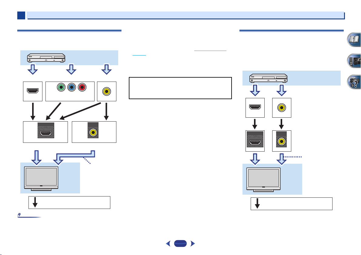
2
About the video converter (VSX-827 only)
The video converter ensures that all video sources are output
from the HDMI OUT terminal.
•
If the video signal does not appear on your TV, try adjusting
the resolution settings on your component or display. Note
that some components (such as video game units) have
resolutions that may not be converted. In this case, try
switching Video Converter OFF (see Video Converter
page 50).
•
The signal input resolutions that can be converted from the
component video input for the HDMI output are 480i/576i,
480p/576p, 720p and 1080i. 1080p signal cannot be
converted.
on
Connecting your equipment
About video outputs connection
(VSX-527 only)
This receiver is not loaded with a video converter. When you
use HDMI cables for connecting to the input device, the same
cables should be used for connecting to the TV.
The signals input from the analog (composite) video inputs of
this unit will not be output from the HDMI OUT terminal.
•
If several video components are assigned to the same input
function, the converter gives priority to HDMI, component,
then composite (in that order).
16
IN
HDMI
OUT
HDMI
IN
VIDEO
MONITOR
OUT
VIDEO
Page 17
2
Note
E
E
Select one
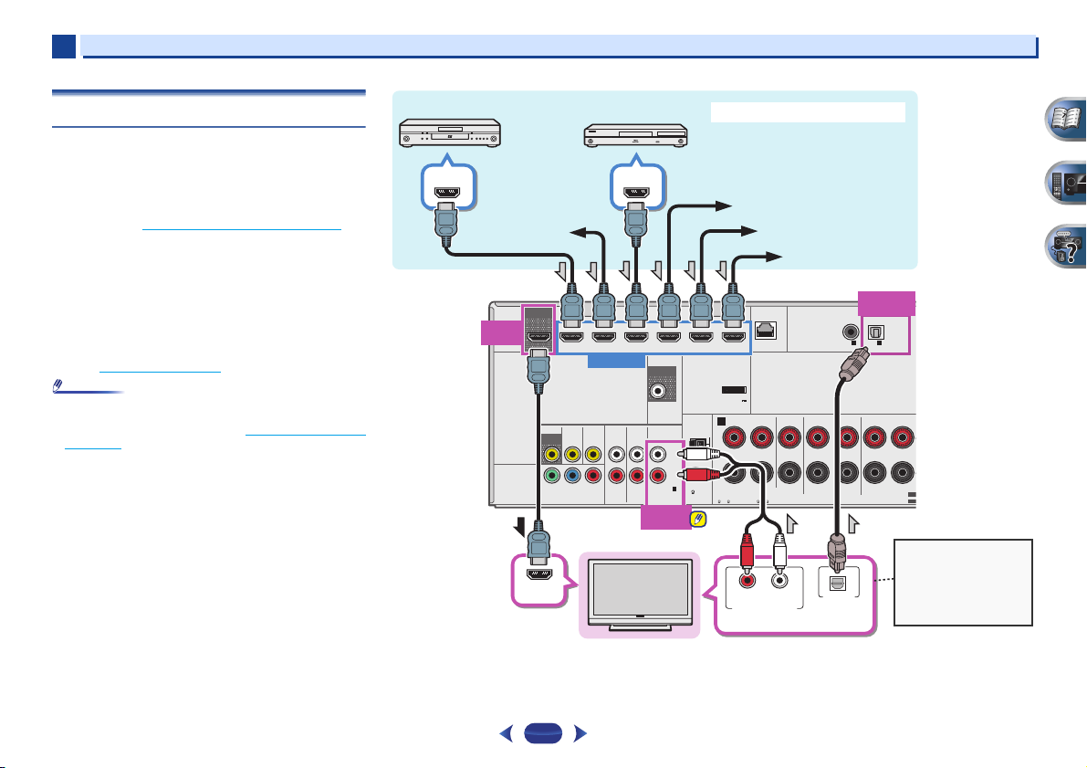
HDMI/DVI-compatible TV
Set-top box
DVD player
Blu-ray Disc player
Game console
HDMI/DVI-compatible components
If the TV does not support
the HDMI Audio Return
Channel function, this
connection is required to
listen to the TV sound over
the receiver.
DVD recorder,
Blu-ray Disc recorder
Video component
VSX-827
2
Connecting a TV and playback components
Connecting using HDMI
If you have an HDMI or DVI (with HDCP) equipped component
(Blu-ray Disc player, etc.), you can connect it to this receiver
using a commercially available HDMI cable.
If the TV and playback components support the Control with
HDMI feature, the convenient Control with HDMI functions
can be used (see Control with HDMI function
•
The following connection/setting is required to listen to the
sound of the TV over this receiver.
-
If the TV does not support the HDMI Audio Return
Channel function, connect the receiver and TV with audio
cables (as shown).
-
If the TV supports the HDMI Audio Return Channel
function, the sound of the TV can be input to the receiver
via the HDMI terminal, so there is no need to connect an
audio cable. In this case, set ARC at HDMI Setup to ON
(see HDMI Setup
•
In or der to liste n to the audi o from the TV tha t is connect ed
to this receiver using an analog audio cables, set-up for
analog audio input is required (see The Input Assign menu
on page 50).
on page 53).
on page 53).
HDMI OUT
HDMI
HDMI
OUT
IN
(
DVD
ASSIGNABLE
OUT
DVD GAME VIDEOBD
VIDEO
MONITOR
OUT
IN
1
1
)
YPBP
COMPONENT VIDEO
HDMI OUT
IN
SAT/CBL DVR/BDR
HDMI IN
PRE OUT
SUB WOOFER
L
IN
R
1
1
ANALOG IN
(CD)
ASSIGNABLE
ANALOG
IN1 (CD)
ANTENNA
AM LOOP
FM UNBAL
75
AUDIO
DVD INSAT/CBL
DVD
SAT/CBL
R
ADAPTER PORT
(
OUTPUT 5 V
0.1 A MAX
A
RL
CAUTION:
SPEAKER IMPEDANCE
6 -16 .
LAN
)
FRONT
ATTENTION:
ENCEINTE D’IMPEDANCE DE
6 -16 .
(10/100
)
CENTER
Connecting your equipment
OPTICAL
IN1 (TV)
COAXIAL
ASSIGNABLE
SURROUND
RLRL
SPEAKERS
IN1IN
(CD)
OPTICAL
ASSIGNABLE
1
(TV)
SURROUND BACK
(
)
Single
SEL
SEL
HDMI IN
17
RL
ANALOG AUDIO OUT
OPTICAL
DIGITAL AUDIO OUT
Page 18
2
Important
Note
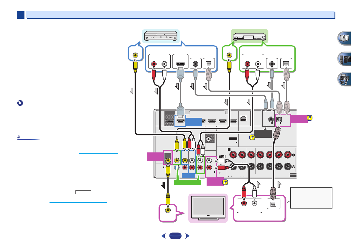
Select one Select one
Select one
TV
DVD player
Set-top box
This connection is
required in order to listen
to the sound of the TV
over the receiver.
VSX-827
2
Connecting your TV with no HDMI input
This diagram shows connections of a TV (with no HDMI input)
and DVD player (or other playback component) to the receiver.
•
With these connections, the picture is not output to the TV
even if the DVD player is connected with an HDMI cable.
Connect the DVD player’s video signals using a composite
cable.
•
In order to listening to HD audio with this receiver, connect
an HDMI cable, and use analog video cable for video signal
input.
Depending on the player, it may not be possible to output
video signals to both HDMI and other video output
(composite, etc.) simultaneously, and it may be necessary
to make video output settings. Please refer to the operating
instructions supplied with your player for more information.
•
When the receiver and TV are connected by composite
cable, the OSD function allowing display of the receiver’s
settings, operations, etc., on the TV’s screen cannot be
used. In this case, watch the receiver’s front panel display
while performing the various operations and making
settings.
•
In or der to liste n to the audi o from the TV tha t is connect ed
to this receiver using a analog audio cables, set-up for
analog audio input is required (see The Input Assign menu
on page 50).
•
Only one component can be connected to both the optical
input terminal and coaxial input terminal. If connecting
other devices, please use a different method to connect the
audio.
In order to listen to the audio from the source component
that is connected to this receiver using an optical cable or
a coaxial cable, first, switch to the DVD (DVD player) or
SAT/CBL (set-top box), then use and
SEL
to choose the audio signal O1 (OPTICAL1) or C1
(COAXIAL1) (see Selecting the audio input signal
page 25).
RECEIVER
SIGNAL
on
Connecting your equipment
L
IN
R
1
1
(CD)
ASSIGNABLE
ANALOG
IN1 (CD)
ANTENNA
AM LOOP
FM UNBAL
75
VIDEO OUT
ADAPTER PORT
(
OUTPUT 5 V
0.1 A MAX
A
CAUTION:
SPEAKER IMPEDANCE
6 -16 .
ANALOG AUDIO OUT
(10/100
LAN
)
FRONT
RL
ATTENTION:
ENCEINTE D’IMPEDANCE DE
6 -16 .
RL
ANALOG AUDIO OUT
RL
)
COAXIAL
ASSIGNABLE
COAXIAL
IN1 (CD)
CENTER
SURROUND
RLRL
SPEAKERS
DIGITAL AUDIO OUT
DIGITAL AUDIO OUT
OPTICALCOAXIAL
OPTICAL
ASSIGNABLE
1
IN1IN
(TV)
(CD)
SURROUND BACK
OPTICAL
(
Single
)
SELECTABLE
SELECTABLE
OPTICAL
IN1 (TV)
VIDEO OUT
ANALOG AUDIO OUT
RL
MONITOR
OUT
HDMI
IN
(
DVD
ASSIGNABLE
OUT
VIDEO
MONITOR
OUT
1
1
)
YPB PR
COMPONENT VIDEO
HDMI OUT
SAT/CBL
DIGITAL AUDIO OUT
HDMI
DVD IN
DVD GAME VIDEOBD
SAT/CBL DVR/BDR
AUDIO
DVD
IN
IN
DVD
SAT/CBL
DVD IN
OPTICALCOAXIAL
IN
PRE OUT
SUB WOOFER
ANALOG IN
SAT/CBL IN
VIDEO IN
18
Page 19
2
Note
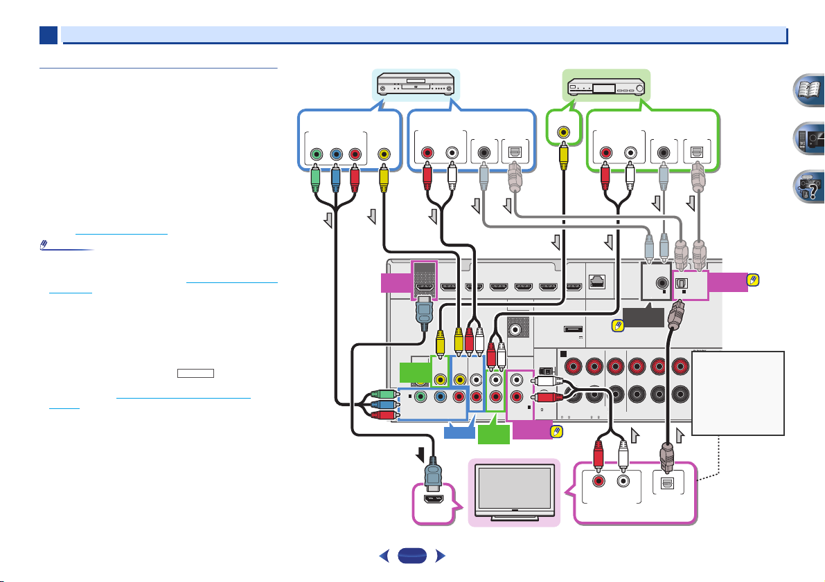
Select one
DVD player
Select one
Select one
Set-top box
If the TV does not
support the HDMI
Audio Return Channel
function, this
connection is required
to listen to the TV
sound over the
receiver.
Select one
HDMI/DVI-compatible TV
2
Connecting your DVD player with no HDMI
output (VSX-827 only)
This diagram shows connections of a TV (with HDMI input)
and DVD player (or other playback component with no HDMI
output) to the receiver.
•
The following connection/setting is required to listen to the
sound of the TV over this receiver.
-
If the TV does not support the HDMI Audio Return
Channel function, connect the receiver and TV with audio
cables (as shown).
-
If the TV supports the HDMI Audio Return Channel
function, the sound of the TV can be input to the receiver
via the HDMI terminal, so there is no need to connect an
audio cable. In this case, set ARC at HDMI Setup to ON
(see HDMI Setup
•
In or der to liste n to the audi o from the TV tha t is connect ed
to this receiver using a analog audio cables, set-up for
analog audio input is required (see The Input Assign menu
on page 50).
•
Only one component can be connected to both the optical
input terminal and coaxial input terminal. If connecting
other devices, please use a different method to connect the
audio.
In order to listen to the audio from the source component
that is connected to this receiver using an optical cable or
a coaxial cable, first, switch to the DVD (DVD player) or
SAT/CBL (set-top box), then use and
SEL
to choose the audio signal O1 (OPTICAL1) or C1
(COAXIAL1) (see Selecting the audio input signal
page 25).
on page 53).
RECEIVER
SIGNAL
on
COMPONENT VIDEO OUT
YPBP
VIDEO OUT
R
ANALOG AUDIO OUT
RL
OUT
HDMI
HDMI
OUT
VIDEO
MONITOR
SAT/CBL
SAT/CBL
OUT
IN
IN
1
1
IN
(
)
DVD
ASSIGNABLE
YPB PR
COMPONENT VIDEO
DIGITAL AUDIO OUT
OPTICALCOAXIAL
DVD GAME VIDEOBD
SAT/CBL DVR/BDR
AUDIO
DVD
IN
DVD
SAT/CBL
SAT/CBL
DVD IN
IN
IN
PRE OUT
SUB WOOFER
IN
ANALOG IN
(CD)
ASSIGNABLE
ANALOG
IN1 (CD)
L
R
1
1
ANTENNA
AM LOOP
FM UNBAL
75
VIDEO OUT
ADAPTER PORT
(
OUTPUT 5 V
0.1 A MAX
A
CAUTION:
SPEAKER IMPEDANCE
6 -16 .
ANALOG AUDIO OUT
(10/100
LAN
)
FRONT
RL
ATTENTION:
ENCEINTE D’IMPEDANCE DE
6 -16 .
Connecting your equipment
RL
)
CENTER
DIGITAL AUDIO OUT
OPTICALCOAXIAL
COAXIAL
ASSIGNABLE
COAXIAL
IN1 (CD)
SURROUND
RLRL
SPEAKERS
IN1IN
(CD)
OPTICAL
ASSIGNABLE
1
(TV)
SURROUND BACK
(
Single
OPTICAL
IN1 (TV)
)
SELECTABLE
SELECTABLE
19
HDMI IN
RL
ANALOG AUDIO OUT
OPTICAL
DIGITAL AUDIO OUT
Page 20
2
Important
Note
N
Bluetooth® ADAPTER
VSX-527
T
C
to LAN port
LAN cable
(sold separately)
Router
Modem
Internet
VSX-527
PC
2
Connecting your equipment
Connecting optional
When the Bluetooth ADAPTER (Pioneer Model No. AS-BT100
or AS-BT200) is connected to this unit, a product equipped
with Bluetooth wireless technology (portable cell phone,
digital music player, etc.) can be used to listen to music
wirelessly.
Connect a
terminal on the rear panel.
•
For instructions on playing the Bluetooth wireless
technology device, see Pairing the
Bluetooth wireless technology device on page 30.
•
Do not move the receiver with the Bluetooth ADAPTER
connected. Doing so could cause damage or faulty contact.
HDMI
Bluetooth
OUT
DVD GAME VIDEOBD
SAT/CBL
MONITOR
OUT
IN
Bluetooth
ADAPTER to the ADAPTER PORT
SAT/CBL DVR/BDR
DVD
IN
DVD
SAT/CBL
VIDEO
®
Bluetooth ADAPTER and
IN
PRE OUT
SUB WOOFER
SURR BACK/
FRONT HEIGHT
L
(
)
Single
ANTENNA
PRE OUT
R
AM LOOP
L
IN
R
FM UNBAL
(CD)
1
1
ANALOG IN
75
ASSIGNABLE
AUDIO
ADAPTER
ADAPTER PORT
(
OUTPUT 5 V
)
0.1 A MAX
FRONT
RL
(
LAN
10/100
SPEAKERS
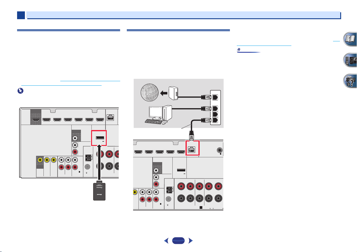
Connecting to the network through LAN
interface
By connecting this receiver to the network via the LAN
terminal, you can listen to Internet radio stations. To listen to
Internet radio stations, you must sign a contract with an ISP
(Internet Service Provider) beforehand.
When connected in this way, you can play audio files stored
on the components on the local network, including your
computer.
)
)
(10/100
ADAPTER PORT
(
OUTPUT 5 V
0.1 A MAX
RL
)
FRONT
LAN
SPEAKERS
CENTER
A
CE
SAT/CBL DVR/BDR
DVD
IN
IDEO
Connect the LAN terminal on this receiver to the LAN terminal
on your router (with or without the built-in DHCP server
function) with a straight LAN cable (CAT 5 or higher).
IN
GAME VIDEOBD
PRE OUT
SUB WOOFER
SURR BACK/
FRONT HEIGHT
L
(
)
Single
ANTENNA
PRE OUT
R
AM LOOP
L
IN
R
FM UNBAL
(CD)
1
1
SAT/CBL
ANALOG IN
DVD
ASSIGNABLE
AUDIO
75
20
WAN
LAN
1
2
3
COAXIAL
ASSIGNABLE
1
IN
(CD)
SURROUND
RL
A
CAUTION:
EN
SPEAKER IMPEDANCE
6
6 -16 .
Turn on the DHCP server f unction of your router. In case you r
router does not have the built-in DHCP server function, it is
necessary to set up the network manually. For details, see The
Network Setup menu on page 41.
•
Refer to the operation manual of the equipment you have as
the connected equipment and connection method may
differ depending on your Internet environment.
•
When using a broadband Internet connection, a contract
with an Internet service provider is required. For more
details, contact your nearest Internet service provider.
Page 21
2
2
1
3
4
75 Ω coaxial cable
One-touch PAL
connector
Outdoor
antenna
5 m to 6 m
Indoor antenna
(vinyl-coated wire)
USB mass
storage device
2
Connecting your equipment
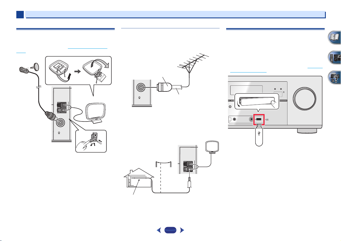
Connecting antennas
Connect the AM loop antenna and the FM wire antenna as
shown below. To improve reception and sound quality,
connect external antennas (see Using external antennas
below).
ANTENNA
AM LOOP
FM UNBAL
75
1
Push open the tabs, then insert one wire fully into each
terminal, then release the tabs to secure the AM antenna
wires.
2
Fix the AM loop antenna to the attached stand.
To fix the stand to the antenna, bend in the direction indicated
by the arrow then clip the loop onto the stand.
3
Place the AM antenna on a flat surface and in a direction
giving the best reception.
4
socket.
For best results, extend the FM antenna fully and fix to a wall
or door frame. Don’t drape loosely or leave coiled up.
Connect the FM wire antenna into the FM antenna
Using external antennas
To improve FM reception
Use a PAL connector (not supplied) to connect an external FM
antenna.
FM UNBAL
75
To improve AM reception
Connect a 5 m to 6 m length of vinyl-coated wire to the AM
antenna terminal without disconnecting the supplied AM
loop antenna.
For the best possible reception, suspend horizontally
outdoors.
ANTENNA
AM LOOP
21
Connecting a USB device
It is possible to play audio and photo files by connecting USB
devices to this receiver.
Switch the receiver into standby then connect your USB
device to the USB terminal on the front panel of this
receiver.
•
This receiver does not support a USB hub.
•
For instructions on playing the USB device, see Playing a
USB device on page 28.
iPod iPhone iPad
HDMI
CONTROL ON / OFF
BAND TUNER EDIT TUNE PRESET ENTER
O SURROUND
/
STANDARD SURR
EAM DIRECT
SOUND
ADVANCED
SURROUND
iPod iPhone iPad
RETRIEVER AIR
DIRECT CONTROL
USB
VIDEO
iPod
iPhone
iPad
MASTER
VOLUME
ALC/
MCACC
SETUP
MIC
Page 22

2
CAUTION
Note
iPod/iPhone/iPad
iPod cable
(VSX-827: supplied/
VSX-527: sold separately)
2
Connecting your equipment
Connecting an iPod
This receiver has a dedicated iPod terminal that will allow you
to control playback of audio content from your iPod using the
controls of this receiver.
Switch the receiver into standby, and then use the iPod
cable to connect your iPod to the iPod iPhone iPad USB
terminal on the front panel of this receiver.
•
VSX-527 only: The iPod cable is not included with this
receiver. The optional iPod cable from Pioneer is sold
separately under the part number L308102013030-IL.
Contact the Pioneer Customer Support division for more
information on obtaining an optional iPod cable.
•
The cable that comes with the iPod can also be used to
connect the iPod. Connect the iPod terminal and the iPod
iPhone iPad USB terminal on the receiver. The videos and
images on the iPod cannot be viewed using this
connection.
•
For the cable connection, refer to also the operating
instructions for iPod.
•
For instructions on playing the iPod, see Playing an iPod on
page 27.
CONTROL ON / OFF
BAND TUNER EDIT TUNE PRESET ENTER
O SURROUND
/
STANDARD SURR
EAM DIRECT
SOUND
ADVANCED
SURROUND
iPod iPhone iPad
RETRIEVER AIR
DIRECT CONTROL
USB
VIDEO
iPod
iPhone
iPad
ALC/
MCACC
SETUP
MIC
Plugging in the receiver
iPod iPhone iPad
HDMI
Only plug in after you have connected all your components to
this receiver, including the speakers.
•
MASTER
VOLUME
Handle the power cord by the plug part. Do not pull out the
plug by tugging the cord, and never touch the power cord
when your hands are wet, as this could cause a short
circuit or electric shock. Do not place the unit, a piece of
furniture, or other object on the power cord or pinch the
cord in any other way. Never make a knot in the cord or tie
it with other cables. The power cords should be routed so
that they are not likely to be stepped on. A damaged power
cord can cause a fire or give you an electric shock. Check
the power cord once in a while. If you find it damaged, ask
your nearest Pioneer authorized independent service
company for a replacement.
•
Do not use any power cord other than the one supplied with
this unit.
•
Do not use the supplied power cord for any purpose other
than that described below.
•
The receiver should be disconnected by removing the
mains plug from the wall socket when not in regular use,
e.g., when on vacation.
•
After this receiver is connected to an AC outlet, a 2 second
to 10 second HDMI initialization process begins. You
cannot carry out any operations during this process. The
HDMI indicator in the front panel display blinks during this
process, and you can turn on this receiver once it has
stopped blinking. When you set the Control with HDMI to
OFF, you can skip this process. For details about the
Control with HDMI feature, see HDMI Setup
1
Plug the supplied power cord into the AC IN socket on
the back of the receiver.
2
Plug the other end into a power outlet.
on page 53.
22
Page 23

Chapter
CAUTION
Important
Tripod
Microphone
Basic Setup
3
3
Canceling the Auto Power Down
When this receiver is not used over a period of several hours,
it will power down automatically. The automatic power-off
timer is set to six hours under factory settings, and the timing
can be changed or the power-off function switched off
altogether. For details, see The Auto Power Down menu
page 52.
on
Canceling the demo display
The display on the front panel shows various information
(demo displays) when the receiver is not operating.
You can turn off the demo display. For details, see The FL
Demo Mode menu on page 52.
•
The demo mode is canceled automatically when the Auto
MCACC setup is performed (see below).
Automatically setting up for surround sound
(MCACC)
The Auto Multi-Channel Acoustic Calibration (MCACC) setup
measures the acoustic characteristics of your listening area,
taking into account ambient noise, speaker size and distance,
and tests for both channel delay and channel level. After you
have set up the microphone provided with your system, the
receiver uses the information from a series of test tones to
optimize the speaker settings and equalization for your
particular room.
•
The test tones used in the Auto MCACC setup are output at
high volume.
•
The OSD will not appear if you have connected using the
composite output to your TV. Use HDMI connection for
Auto MCACC setup.
•
The Auto MCACC setup will overwrite any existing speaker
settings you’ve made.
•
Before using the Auto MCACC setup, the NETRADIO,
M.SERVER, FAVORITE, iPod/USB or ADAPTER input
should not be selected as an input source.
•
VSX-827 only: When both the surround back speaker and
the front height speaker are connected, conduct Auto
MCACC setup twice: once with the Speaker System setting
is in Surr.Back and once with the Speaker System setting
is in Height. (There is no need to conduct Auto MCACC
setup every time the Speaker System setting is changed.)
•
VSX-527 only: If you connected either the surround back
speaker or the front height speaker, make sure that the Pre
Out setting is correctly set before performing the Auto
MCACC setup (see page 51
the OSD screen for a surround back speaker connection.)
Switch on the receiver and your TV.
1
Switch the TV input to the input that connects this
2
receiver to the TV through the corresponding HDMI
cable.
Connect the microphone to the MCACC SETUP MIC jack
3
on the front panel.
Make sure there are no obstacles between the speakers
and the microphone.
). (Here is an explanation using
iPod iPhone iPad
HDMI
CONTROL ON / OFF
BAND TUNER EDIT TUNE PRESET ENTER
O SURROUND
/
STANDARD SURR
EAM DIRECT
If you have a tripod, use it to place the microphone so that
it’s about ear level at your normal listening position.
Otherwise, place the microphone at ear level using a
table or a chair.
Press on the remote control, then press the
4
HOME MENU
The Home Menu appears on your TV. Use
ENTER
screens and select menu items. Press
the current menu.
•
•
SOUND
ADVANCED
RETRIEVER AIR
SURROUND
VIDEO
iPod
iPhone
iPad
RECEIVER
iPod iPhone iPad
DIRECT CONTROL
USB
ALC/
MCACC
SETUP
MIC
button.
on the remote control to navigate through the
Press
HOME MENU
Menu. If you cancel the Auto MCACC setup at any
time, the receiver automatically exits and no settings
will be made.
The screensaver automatically starts after three
minutes of inactivity.
at any time to exit the Home
///
RETURN
MASTER
VOLUME
to exit
and
23
Page 24

3
Note
Home Menu
1
. Auto MCACC
2
. Manual SP Setup
3
. Input Assign
4
. Speaker System
5
. Video Parameter
6
. HDMI Setup
7
. Auto Power Down
8
. Network Standby
9
. FL Demo Mode
Home Menu
1
. Auto MCACC
2
. Manual SP Setup
3
. Input Assign
4
. Pre Out Setting
5
. HDMI Setup
6
. Auto Power Down
7
. Network Standby
8
. FL Demo Mode
VSX-827
VSX-527
3
Basic Setup
5
6
7
Select ‘Auto MCACC’ from the Home Menu, then press
ENTER
.
•
Mic In! blinks when the microphone is not connected
to MCACC SETUP MIC jack.
Try to be as quiet as possible after pressing
system outputs a series of test tones to establish the
ambient noise level.
ENTER
. The
Follow the instructions on-screen.
•
Make sure the microphone is connected.
•
Make sure the subwoofer is on and the volume is
turned up.
•
When using surround back or front height speakers,
turn on the power to the amplifier to which the
surround back or front height speakers are connected,
and adjust the sound level to the desired level.
•
See below for notes regarding background noise and
other possible interference.
Wait for the test tones to finish.
A progress report is displayed on-screen while the
receiver outputs test tones to determine the speakers
present in your setup. Try to be as quiet as possible while
it’s doing this.
1 . Auto MCACC
Now Analyzing
Environment Check
Ambient Noise
Speaker YES/NO
•
For correct speaker settings, do not adjust the volume
during the test tones.
Return
Confirm the speaker configuration.
8
The configuration shown on-screen should reflect the
actual speakers you have.
1 . Auto MCACC
Check!
[ YES ]
Front
[ YES ]
Center
[ YES ]
Surr
Surr. Back
Subwoofer
10:Next
•
With error messages (such as Too much ambient
noise) select RETRY after checking for ambient noise
(see Other problems when using the Auto MCACC
setup below).
If the speaker configuration displayed isn’t correct, use
/
to select the speaker and
setting. When you’re finished, go to the next step.
If you see an error message (ERR) in the right side
column, there may be a problem with the speaker
connection. If selecting RETRY doesn’t fix the problem,
turn off the power and check the speaker connections.
Make sure ‘OK’ is selected, then press
9
If the screen in step 8 is left untouched for 10 seconds
and
ENTER
setup will start automatically as shown.
A progress report is displayed on-screen while the
receiver outputs more test tones to determine the
optimum receiver settings for channel level, speaker
distance, and Acoustic Calibration EQ.
Again, try to be as quiet as possible while this is
happening. It may take 1 to 3 minutes.
is not pressed in step 9, the Auto MCACC
1 . Auto MCACC
Now Analyzing
Surround Analyzing
Speaker System
Speaker Distance
Channel Level
Acoustic Cal EQ
---
[
[ YES ]
]
/
OK
Return
Return
to change the
ENTER
24
The Auto MCACC setup has finished! You return to the
10
Home Menu.
The settings made in the Auto MCACC setup should give
you excellent surround sound from your system, but it is
also possible to adjust these settings manually using the
Home Menu (starting on page 47
•
Depending on the characteristics of your room, sometimes
identical speakers with cone sizes of around 12 cm will end
up with different size settings. You can correct the setting
manually using the Speaker Setting
•
The subwoofer distance setting may be farther than the
actual distance from the listening position. This setting
should be accurate (taking delay and room characteristics
into account) and generally does not need to be changed.
).
on page 47.
Other problems when using the Auto MCACC
setup
If the room environment is not optimal for the Auto MCACC
setup (too much background noise, echo off the walls,
obstacles blocking the speakers from the microphone) the
final settings may be incorrect. Check for household
.
appliances (air conditioner, fridge, fan, etc.), that may be
affecting the environment and switch them off if necessary. If
there are any instructions showing in the front panel display,
please follow them.
•
Some older TVs may interfere with the operation of the
microphone. If this seems to be happening, switch off the
TV when doing the Auto MCACC setup.
Page 25

Chapter
Note
Note
ENTER
MUTE
RETURN
AUDIO
PARAMETER
MENU
HOME
MENU
TOOLS
BAND
iPod CTRL
PTY
TOP
MENU
T
U
N
E
T
U
N
E
P
R
E
S
E
T
P
R
E
S
E
T
4
4
Basic playback
Playing a source
Here are the basic instructions for playing a source (such as
a DVD disc) with your home theater system.
SLEEP
SOURCE
RECEIVER
Switch on your system components and receiver.
1
Start by switching on the playback component (for
example a DVD player), your TV and subwoofer (if you
have one), then the receiver (press
•
Make sure the setup microphone is disconnected.
Switch the TV input to the input that connects this
2
receiver.
For example, if you connected this receiver to the VIDEO
jacks on your TV, make sure that the VIDEO input is now
selected.
Press input function buttons to select the input function
3
you want to play.
•
The input of the receiver will switch over, and you will
be able to operate other components using the remote
control. To operate the receiver, first press
on the remote control, then press the appropriate
button to operate.
•
The input source can also be selected by using
SELECT
using the front panel
case, the remote control won’t switch operational
modes.
INPUT
buttons on the remote control, or by
INPUT SELECTOR
RECEIVER
).
RECEIVER
INPUT
dial. In this
If you selected the proper input source and there is still
no sound, select the audio input signal for playback (see
Selecting the audio input signal
Press
AUTO/DIRECT
4
start playback of the source.
If you’re playing a Dolby Digital or DTS surround sound
DVD disc, with a digital audio connection, you should
hear surround sound. If you’re playing a stereo source or
if the connection is an analog audio connection, you will
only hear sound from the front left/right speakers in the
default listening mode.
It is possible to check on the front panel display whether
or not surround sound playback is being performed
properly.
When using a surround back speaker, 2D+PLIIx is
displayed when playing Dolby Digital 5.1-channel signals,
and DTS+NEO:6 is displayed when playing DTS 5.1channel signals.
When not using a surround back speaker, 2D is
displayed when playing Dolby Digital signals.
If the display does not correspond to the input signal and
listening mode, check the connections and settings.
•
You may need to check the digital audio output settings on
your DVD player or digital satellite receiver. It should be set
to output Dolby Digital, DTS and 88.2 kHz/96 kHz PCM (2
channel) audio, and if there is an MPEG audio option, set
this to convert the MPEG audio to PCM.
•
Depending on your DVD player or source discs, you may
only get digital 2 channel stereo and analog sound. In this
case, the receiver must be set to a multichannel listening
mode if you want multichannel surround sound.
Use
VOLUME +/–
5
Turn down the volume of your TV so that all sound is
coming from the speakers connected to this receiver.
to adjust the volume level.
below).
to select ‘AUTO SURROUND’ and
25
Selecting the audio input signal
The audio input signal can be selected for each input source.
Once it is set, the audio input that was selected will be applied
whenever you select the input source using the input function
buttons.
RECEIVER
SLEEP
SOURCE
INPUT
RECEIVER
Press , then press
audio input signal corresponding to the source
component.
1
4
7
CLR
SIGNAL SEL
Each press cycles through the following:
•
H – Selects an HDMI signal. H can be selected for BD,
DVD, SAT/CBL, DVR/BDR, VIDEO or GAME input. For
other inputs, H cannot be selected.
-
When the HDMI option in Setting the Audio options
on page 37 is set to THRU, the sound will be heard
through your TV, not from this receiver.
•
A – Selects the analog inputs.
•
C1/O1 – Selects the digital input. The coaxial 1 input is
selected for C1, and the optical 1 audio input is
selected for O1.
When H (HDMI) or C1/O1 (digital) is selected and the
selected audio input is not provided, A (analog) is
automatically selected.
•
BD, DVR/BDR, VIDEO and GAME inputs are fixed to H
(HDMI). It cannot be changed.
•
For the TV input, only A (analog) or C1/O1 (digital) can be
selected. However, if the ARC at HDMI Setup is set to ON,
the input is fixed to H (HDMI) and cannot be changed.
•
When set to H (HDMI) or C1/O1 (digital), 2 lights when a
Dolby Digital signal is input, and DTS lights when a DTS
signal is input.
•
When the H (HDMI) is selected, the A and DIGITAL
indicators are off (see page 8
).
DISP
2
3
CH
5
6
CH
8
9
SHIFT
ENTER
0
to select the
Page 26

4
Tip
L
L
Audio
Audio
Audio
Audio
Video/Audio (HDMI)
Video
Other than TV input
(TV input)
Video (VSX-827 only)
Reassignable
(page 50)
4
•
When digital input (optical or coaxial) is selected, this
receiver can only play back Dolby Digital, PCM (32 kHz to
96 kHz) and DTS (including DTS 96 kHz/24 bit) digital signal
formats. The compatible signals via the HDMI terminals
are: Dolby Digital, DTS, SACD (DSD 2 ch only), PCM
(32 kHz to 192 kHz sampling frequencies), Dolby TrueHD,
Dolby Digital Plus, DTS-EXPRESS, DTS-HD Master Audio
and DVD Audio (including 192 kHz). With other digital
signal formats, set to A (analog).
•
You may get digital noise when a LD or CD player
compatible with DTS is playing an analog signal. To prevent
noise, make the proper digital connections (page 15
set the signal input to C1/O1 (digital).
•
Some DVD players don’t output DTS signals. For more
details, refer to the instruction manual supplied with your
DVD player.
) and
Basic playback
•
In order to enjoy the picture and/or sound from devices connected to each terminal, select the input by doing the following.
CD
SIGNAL SEL
3
(TV)
SIGNAL SEL
SURROUND BACK
3
).
TV
C1
OPTICAL
ASSIGNABLE
1
O1
(
Single
SELECTAB
SELECTAB
HDMI
SAT/CBL
OUT
VIDEO
MONITOR
DVD
1
1
IN
(
)
DVD
ASSIGNABLE
COMPONENT VIDEO
DVD
DVD BD
DVD GAME VIDEOBD
DVD
SAT/CBL
DVD
SAT/CBL
OUT
IN
IN
YPB PR
SAT/CBL
SAT/CBL DVR/BDR
RECEIVER
GAME VIDEODVR/ BDR NETWORK
IN
PRE OUT
SUB WOOFER
SIGNAL SEL
A
3
A
ANTENNA
AUDIO
DVD
SAT/CBL
ANALOG IN
ASSIGNABLE
CD
(CD)
TV
L
IN
R
1
1
RECEIVER
AM LOOP
FM UNBAL
75
ADAPTER PORT
(
OUTPUT 5 V
0.1 A MAX
A
TUNER
CAUTION:
SPEAKER IMPEDANCE
6 -16 .
SIGNAL SEL
3
(10/100
LAN
ADAPTER
)
FRONT
RL
ATTENTION:
ENCEINTE D’IMPEDANCE DE
6 -16 .
A
DVD
SAT/CBL
RECEIVER
)
COAXIAL
ASSIGNABLE
IN1IN
(CD)
TV
1.
2.
RECEIVER
CENTER
SURROUND
RLRL
SPEAKERS
ANALOG IN1 audio input terminal is
assigned to CD under factory settings.
If you want to change this to TV input,
please change the settings in the Input
Assign menu (page 50
)
26
Page 27

4
Important
Note
Tip
Important
4
Playing an iPod
This receiver has the iPod iPhone iPad USB terminal that will
allow you to control playback of audio content from your iPod
using the controls of this receiver.
•
Pioneer cannot under any circumstances accept
responsibility for any direct or indirect loss arising from any
inconvenience or loss of recorded material resulting from
the iPod failure.
•
About one minute is required between turning the power
on and completion of startup.
•
This receiver is compatible with the audio and video of the
iPod nano 3G/4G/5G/6G (audio only for the iPod nano 6G),
iPod touch 1G/2G/3G/4G, iPhone, iPhone 3G, iPhone 3GS,
iPhone 4, iPhone 4S, iPad and iP ad 2 . Ho we ver , so me of t he
functions may be restricted for some models. The receiver
is not compatible with the iPod shuffle.
•
This receiver has been developed and tested for the
software version of iPod/iPhone/iPad indicated on the
website of Pioneer (http://pioneer.jp/homeav/support/ios/
eu/).
•
Installing software versions other than indicated on the
website of Pioneer to your iPod/iPhone/iPad may result in
incompatibility with this receiver.
•
iPod, iPhone and iPad are licensed for reproduction of noncopyrighted materials or materials the user is legally
permitted to reproduce.
•
Features such as the equalizer cannot be controlled using
this receiver, and we recommend switching the equalizer
off before connecting.
•
Make sure the receiver is in standby when disconnecting
the iPod/iPhone/iPad.
Switch on the receiver and your TV.
1
See Connecting an iPod on page 22.
Switch the TV input so that it connects to the receiver.
2
•
Switch the TV input to the input that connects this
receiver to the TV through the corresponding HDMI
cable.
Press
iPod/USB
3
input.
When the display shows the names of folders and files,
you’re ready to play music from the iPod.
•
If after pressing
DEVICE, try switching off the receiver and
reconnecting the iPod to the receiver.
•
The controls of your iPod will be inoperable when
connected to this receiver.
to switch the receiver to the iPod/USB
iPod/USB
the display shows NO
Playing back files stored on an iPod
To navigate songs on your iPod, you can take advantage of the
OSD of your TV connected to this receiver.
•
Note that non-roman characters in the title are displayed as
‘#’.
•
This feature is not available for photos or video clips on your
iPod.
Finding what you want to play
When your iPod is connected to this receiver, you can browse
songs stored on your iPod by playlist, artist, album name,
song name, genre or composer, similar to using your iPod
directly.
Use
/
1
2
3
•
If you’re in the song category, you can also press
start playback.
•
You can play all of the songs in a particular category by
selecting the All item at the top of each category list. For
example, you can play all the songs by a particular artist.
to select a category, then press
browse that category.
•
To return to the previous level any time, press
Use
/
to browse the selected category (e.g.,
albums).
•
Use
/
to move to previous/next levels.
Continue browsing until you arrive at what you want to
play, then press
to start playback.
ENTER
to
RETURN
ENTER
to
Basic playback
Basic playback controls
This receiver’s remote control buttons can be used for basic
playback of files stored on an iPod.
•
Press
iPod/USB
USB operation mode.
AUDIO
PARAMETER
T
E
S
E
R
P
HOME
MENU
PTY
iPod CTRL
to switch the remote control to the iPod/
TOOLS
MENU
N
U
E
T
P
R
E
S
ENTER
T
E
T
E
U
N
1
4
7
2
3
5
6
8
9
Watching photos and video content
To view photos or video on your iPod, since video control is not
possible using this receiver, you must use the main controls
of your iPod instead.
•
VSX-527 only:
-
In order to display the images or video on the iPod on the
receiver, an iPod cable sold separately is required.
-
To play photos or video on your iPod, you must connect
.
the composite MONITOR OUT jack and TV. The photos
and video content will not appear if you have connected
using the HDMI output to your TV.
•
iPod photos and video content can be viewed only when the
iPod is connected to the iPod VIDEO input on the front
panel.
•
This feature can only be used with an iPod having video
output.
Press
iPod CTRL
1
and video playback.
The receiver controls will be unavailable while you are
watching iPod videos or browsing photos.
to switch to the iPod controls for photo
MUTE
SHIFT
DISP
CH
CH
27
Page 28

4
Tip
Important
Note
Tip
TOP
T
E
4
Basic playback
Press
iPod CTRL
2
controls when you’re done.
•
Change the receiver’s input to the iPod in one action by
pressing
front panel to enable iPod operations on the iPod.
again to switch back to the receiver
iPod iPhone iPad DIRECT CONTROL
Playing a USB device
It is possible to play files using the USB interface on the front
of this receiver.
•
Pioneer cannot guarantee compatibility (operation and/or
bus power) with all USB mass storage devices and
assumes no responsibility for any loss of data that may
occur when connected to this receiver.
•
About one minute is required between turning the power
on and completion of startup.
•
Compatible USB devices include external magnetic hard
drives, portable flash memory (particularly keydrives) and
digital audio players (MP3 players) of format FAT16/32.
•
Copyrighted audio files cannot be played back on this
receiver.
•
With large amounts of data, it may take longer for the
receiver to read the contents of a USB device.
•
If the file selected cannot be played back, this receiver
automatically skips to the next file playable.
•
When the file currently being played back has no title
assigned to it, the file name is displayed in the OSD instead;
when neither the album name nor the artist name is
present, the row is displayed as a blank space.
•
Make sure the receiver is in standby when disconnecting
the USB device.
Switch on the receiver and your TV.
1
See Connecting a USB device on page 21.
Switch the TV input so that it connects to the receiver.
2
•
Switch the TV input to the input that connects this
receiver to the TV through the corresponding HDMI
cable.
on the
Press
iPod/USB
3
receiver to the iPod/USB input.
When the display shows the names of folders and files,
you’re ready to play from the USB device.
If a USB Error message lights in the display, try following
the points below:
•
Switch the receiver off, then on again.
•
Reconnect the USB device with the receiver switched
off.
•
Select another input source (like BD), then switch back
to iPod/USB.
•
Use a dedicated AC adapter (supplied with the device)
for USB power.
If this doesn’t remedy the problem, it is likely your USB
device is incompatible.
on the remote control to switch the
Playing back audio files stored on a USB memory
device
The maximum number of levels that you can select in Step 1
(below) is 9.
•
Note that non-Roman characters in the playlist are
displayed as ‘#’.
Use
/
1
2
Basic playback controls
This receiver’s remote control buttons can be used for basic
playback of files stored on USB devices.
•
Press
USB operation mode.
to select a folder, then press
that folder.
•
To return to the previous level any time, press
Continue browsing until you arrive at what you want to
play, then press
iPod/USB
to start playback.
to switch the remote control to the iPod/
ENTER
to browse
RETURN
AUDIO
PARAMETER
HOME
MENU
PTY
iPod CTRL
TOOLS
MENU
N
U
E
T
ENTER
T
P
R
E
S
E
T
E
U
N
1
2
3
4
5
6
7
8
9
T
E
S
E
R
P
Playing back photo files stored on a USB memory
device
Use
/
1
2
to select a folder, then press
that folder.
•
For high resolution files, some time may be required
for the photo to appear.
•
To return to the previous level any time, press
Continue browsing until you arrive at what you want to
play, then press
The selected content is displayed in full screen and a
slideshow starts.
to start playback.
ENTER
Basic playback controls
HOME
MENU
MENU
PTY
T
E
S
E
R
iPod CTRL
P
ENTER
T
P
R
E
S
E
T
E
U
N
BAND
RETURN
MUTE
– Starts displaying a photo and playing a slideshow.
.
ENTER,
– Stops the player and returns to the previous menu.
•
Slideshows of photo files can be played while listening to
music files by returning to the folder/file list display while
playing a music file on a USB device then playing the photo
files.
MUTE
DISP
CH
CH
SHIFT
to browse
RETURN
.
28
Page 29

4
4
Basic playback
About playable file formats
The USB function of this receiver supports the following file
formats. Note that some file formats are not available for
playback although they are listed as playable file formats.
Music files
Extension Stream
MP3 (MPEG-1 Audio Layer 3)
a
.mp3
Sampling frequency 32 kHz, 44.1 kHz, 48 kHz
Quantization bitra te 16 bit
Channel 2 ch
Bitrate 8 kbps to 320 kbps
VBR/CBR Supported/Supported
WAV (LPCM)
.wav Sampling frequency 32 kHz, 44.1 kHz, 48 kHz,
Quantization bitrate 16 bit, 24 bit
Channel 2 ch
88.2 kHz, 96 kHz,
176.4 kHz, 192 kHz
WMA (WMA2/7/8/9)
b
.wma
Sampling frequency 32 kHz, 44.1 kHz, 48 kHz
Quantization bitra te 16 bit
Channel 2 ch
Bitrate 5 kbps to 320 kbps
VBR/CBR Supported/Supported
AAC (MPEG-4 AAC LC, MPEG-4 HE AAC (aacPlus v1/2))
c
.m4a
.aac
.3gp
.3g2
Sampling frequency 32 kHz, 44.1 kHz, 48 kHz
Quantization bitra te 16 bit
Channel 2 ch
Bitrate 16 kbps to 320 kbps
VBR/CBR Supported/Supported
FLAC
d
.flac
a.
b. Files encoded using Windows Media Codec 9 may be playable
c. Apple lossless encoding is not supported.
d. Uncompressed FLAC files are not supported. Pioneer does not
Sampling frequency 32 kHz, 44.1 kHz, 48 kHz,
Quantization bitrate 16 bit, 24 bit
Channel 2 ch
MPEG Layer-3 audio decoding technology licensed from
Fraunhofer IIS and Thomson multimedia.
but some parts of the specification are not supported;
specifically, Pro, Lossless, Voice.
guarantee playback.
88.2 kHz, 96 kHz,
176.4 kHz, 192 kHz
Photo files
Extension Format
JPEG
.jpg Meeting the following conditions:
• Baseline JPEG format
• Y:Cb:Cr - 4:2:2
29
Page 30

4
Important
Bluetooth wireless technology enabled device:
cell phone
Bluetooth wireless technology enabled device:
Digital music player
Device not equipped with Bluetooth wireless
technology: Digital music player + Bluetooth
audio transmitter (sold commercially)
Music data
Remote control
operation
Bluetooth®
ADAPTER
This receiver
4
Basic playback
Bluetooth
®
ADAPTER for Wireless Enjoyment
of Music
Wireless music play
When the Bluetooth ADAPTER (Pioneer Model No. AS-BT100
or AS-BT200) is connected to this unit, a product equipped
with Bluetooth wireless technology (portable cell phone,
digital music player, etc.) can be used to listen to music
wirelessly. Also, by using a commercially available transmitter
supporting Bluetooth wireless technology, you can listen to
music on a device not equipped with Bluetooth wireless
technology. The AS-BT100 and AS-BT200 model supports
SCMS-T contents protection, so music can also be enjoyed on
devices equipped with SCMS-T type Bluetooth wireless
technology.
•
The Air Jam function cannot be used with the AS-BT100.
•
It must be necessary that the Bluetooth wireless technology
enabled device supports A2DP profiles.
•
Pioneer does not guarantee proper connection and
operation of this unit with all Bluetooth wireless technology
enabled devices.
•
About one minute is required between turning the power
on and completion of startup.
Remote control operation
The remote control supplied with this unit allows you to play
and stop media, and perform other operations.
•
It must be necessary that the Bluetooth wireless technology
enabled device supports AVRCP profiles.
•
Remote control operations cannot be guaranteed for all
Bluetooth wireless technology enabled devices.
Pairing the
Bluetooth
ADAPTER and
Bluetooth
wireless technology device
“Pairing” must be done before you start playback of Bluetooth
wireless technology content using Bluetooth ADAPTER. Make
sure to perform pairing first time you operate the system or
any time pairing data is cleared. “Pairing” is the step
necessary to register Bluetooth wireless technology device to
enable Bluetooth communications. For more details, see also
the operating instructions of your Bluetooth wireless
technology device.
•
Pairing is required when you first use Bluetooth wireless
technology device and Bluetooth ADAPTER.
•
To enable Bluetooth communication, pairing should be
done with both of your system and Bluetooth wireless
technology device.
•
If the Bluetooth wireless technology device’s security code
is “0000”, there is no need to make the security code setting
on the receiver. Press
input, then conduct the pairing operation on the Bluetooth
wireless technology device. If pairing is successful, there is
no need to performing the pairing operation below.
•
When using the AS-BT200 only: This unit complies with
Bluetooth Specifications Ver. 2.1. When this unit and
another device equipped with Bluetooth wireless
technology both comply with Bluetooth Specification Ver.
2.1, pairing of the two may be possible without the need for
inputting a password.
In this case, a passcode may be displayed on this receiver
ADAPTER
to switch the ADAPTER
and on the device equipped with Bluetooth wireless
technology. If this happens, check that the same passcode
is displayed on this receiver and the device equipped with
Bluetooth wireless technology, then press
this, also perform the connection operation on the
Bluetooth device to be connected. If the passcode does not
match the code displayed on the Bluetooth device to be
connected, press
starting over.
Press
ADAPTER
the pairing operation on the Bluetooth wireless technology
device. If pairing is successful, there is no need to
performing the pairing operation below.
•
Pair one unit at a time.
•
When connecting this receiver by Bluetooth connections
with a device equipped with the Bluetooth function to listen
to music, do not connect any devices other than this
receiver by Bluetooth connection to the Bluetooth-equipped
device. If a Bluetooth connection is already established with
a device other than this receiver, disconnect the other
device before connecting this receiver.
Press
1
input.
Press
2
Use
/
3
Use
/
4
then press
You can use any of 0000/1234/8888 PIN codes.
Bluetooth wireless technology device using any other PIN
code cannot be used with this system.
Switch on the
5
that you want to make pairing, place it near the system
and set it into the pairing mode.
Check to see that the
6
the
Bluetooth
When Bluetooth wireless technology device is connected:
Bluetooth wireless technology device name appears in
the receiver display.
•
The system can display alphanumeric characters only.
Other characters may not be displayed correctly.
RETURN
to cancel pairing, then try
to set the ADAPTER input, then conduct
ADAPTER
to switch the receiver to ADAPTER
TOP MENU
to select Bluetooth Setup.
to select PIN, then press
to select one of PIN codes 0000, 1234 or 8888,
ENTER
.
Bluetooth
wireless technology device
Bluetooth
wireless technology device.
ENTER
. After
ENTER
.
ADAPTER is detected by
30
Page 31

4
4
Basic playback
When Bluetooth wireless technology device is not
connected:
WAITING appears in the receiver display. In this case,
perform the connection operation from the side of the
Bluetooth wireless technology device.
From the
Bluetooth
7
select
Bluetooth
selected in the step 4.
•
PIN code may in some case be referred to as
PASSKEY.
Listening to Music Contents of
wireless technology device list,
ADAPTER and enter the PIN code
Bluetooth
technology device with Your System
Press
ADAPTER
1
input.
The ADAPTER input can also be selected by pressing
SOUND RETRIEVER AIR
S.R AIR, the optimum listening mode, is selected
automatically.
Perform the connection operation from the side of the
2
Bluetooth
ADAPTER.
•
When the Bluetooth ADAPTER is not plugged into the
ADAPTER PORT terminal, NO ADP will be displayed if
ADAPTER input is selected.
Start playback of music contents stored in
3
wireless technology device.
This receiver’s remote control buttons can be used for
basic playback of files stored on the Bluetooth wireless
technology device.
•
Bluetooth wireless technology device should be
compatible with AVRCP profile.
•
Depending on Bluetooth wireless technology device
you use, operation may differ from what is shown in
the remote control buttons.
to switch the receiver to ADAPTER
on the front panel. In this case,
wireless technology device to the
Bluetooth
wireless
Bluetooth
While listening to a source, press then press
4
ADV SURR
repeatedly to select S.R AIR.
RECEIVER
AIR JAM
Air Jam – a Pioneer-exclusive application and available for
free.
Air Jam lets you connect multi compatible devices to this unit
using Bluetooth wireless technology. With it, you can make a
group playlist directly on a supported device to play in your
home theater through the unit. You and your friends can add
songs from your devices to the playlist. Also Air Jam lets you
delete the song before anyone has to hear it.
Press
ADAPTER
1
input.
Press
2
Use
/
3
Use
/
4
For more details on using Air Jam, access our website.
http://pioneer.jp/support/soft/iapp_airjam/en.html
The Bluetooth
trademarks owned by Bluetooth SIG, Inc. and any use of such
marks by PIONEER CORPORATION is under license. Other
trademarks and trade names are those of their respective
owners.
to switch the receiver to ADAPTER
TOP MENU
to select Bluetooth Setup.
to select ‘Air Jam’, then press
to select ‘Air Jam ON’, then press
®
word mark and logos are registered
ENTER
ENTER
.
.
31
Page 32

4
Note
Tip
ENTER
MUTE
AUDIO
PARAMETER
MENU
HOME
MENU
TOOLS
iPod CTRL
PTY
TOP
MENU
P
R
E
S
E
T
P
R
E
S
E
T
4
Basic playback
Listening to the radio
The following steps show you how to tune in to FM and AM
radio broadcasts using the automatic (search) and manual
(step) tuning functions. Once you are tuned to a station you
can memorize the frequency for recall later—see Saving
station presets below for more on how to do this.
Press
TUNER
to select the tuner.
BAND
to change the band (FM or AM), if necessary.
TUNE
/
for about a second. The
/
.
TUNE
/
for high speed tuning.
1
Use
2
Each press switches the band between FM (stereo or
mono) and AM.
Tune to a station.
3
There are three ways to do this:
Automatic tuning
To search for stations in the currently selected band,
press and hold
receiver will start searching for the next station, stopping
when it has found one. Repeat to search for other
stations.
Manual tuning
To change the frequency one step at a time, press
TUNE
High speed tuning
Press and hold
Release the button at the frequency you want.
Improving FM sound
If the TUNE or ST indicators don’t light when tuning to an FM
station because the signal is weak, set the receiver to the
mono reception mode.
Press
BAND
This should improve the sound quality and allow you to
enjoy the broadcast.
to select FM MONO.
Saving station presets
If you often listen to a particular radio station, it’s convenient
to have the receiver store the frequency for easy recall
whenever you want to listen to that station. This saves the
effort of manually tuning in each time. This unit can memorize
up to 30 stations.
AUDIO
PARAMETER
TOP
RECEIVER
SLEEP
SOURCE
INPUT
Tune to a station you want to memorize.
1
See Listening to the radio above for more on this.
Press
TOOLS
PRESET
.
/
2
The display shows PRESET, then a blinking MEM and
station preset.
Press
3
want.
MENU
ENTER
HOME
MENU
PTY
iPod CTRL
1
MUTE
DISP
2
3
to select the station preset you
You can also use the number buttons.
Press
ENTER
4
The preset number stop blinking and the receiver stores
the station.
.
32
•
If the receiver is left disconnected from the AC power outlet
for over a month, the station memories will be lost and will
have to be reprogrammed.
•
Stations are stored in stereo. When the station is stored in
the FM MONO mode, it shows as ST when recalled.
Listening to station presets
You will need to have some presets stored to do this. See
Saving station presets
Press
PRESET
want.
•
You can also use the number buttons on the remote
control to recall the station preset.
above if you haven’t done this already.
/
to select the station preset you
Naming preset stations
For easier identification, you can name all of your preset
stations.
Choose the station preset you want to name.
1
See Listening to station presets above for how to do this.
Press
TOOLS
2
The cursor at the first character position is blinking on
the display.
Input the name you want.
3
Choose a name up to eight characters long.
•
Use
•
Use
•
The name is stored when
•
To erase a station name, follow steps 1 and 2, and press
ENTER
display is blank, to keep the previous name.
•
Once you have named a station preset, Press
the name. When you want to return to the frequency
display, press
twice.
PRESET
/
TUNE
to select character position.
/
to select characters.
ENTER
while the display is blank. Press
DISP
several times to show the frequency.
is pressed.
TOOLS
DISP
while the
to show
Page 33

4
Note
Note
4
Basic playback
An introduction to RDS
Radio Data System (RDS) is a system used by most FM radio
stations to provide listeners with various kinds of
information—the name of the station and the kind of show
they’re broadcasting, for example.
One feature of RDS is that you can s earc h by t ype o f pro gram .
For example, you can search for a station that’s broadcasting
a show with the program type, JAZZ.
You can search the following program types:
NEWS – News
AFFAIRS – Current Affairs
INFO – General Information
SPORT – Sport
EDUCATE – Educational
DRAMA – Radio plays, etc.
CULTURE – National or
regional culture, theate r, etc.
SCIENCE – Science and
technology
VARIED – Usually talk-based
material, such as quiz shows
or interviews.
POP M – Pop music
ROCK M – Rock music
EASY M – Easy listening
LIGHT M – ‘Light’ classical
music
CLASSICS – ‘Serious’ classical
music
OTHER M – Music not fitting
above categories
WEATHER – Weather reports
•
In addition, there are three other program types, ALARM,
ALARMTST, and NO TYPE. ALARM and ALARMTST are
used for emergency announcements. NO TYPE appears
when a program type cannot be found.
FINANCE – Stock market
reports, commerce, trading,
etc.
CHILDREN – Programs for
children
SOCIAL – Social affairs
RELIGION – Programs
concerning religion
PHONE IN – Public expressing
their views by phone
TRAVEL – Holiday-type travel
rather than traffic
announcements
LEISURE – Leisure interests
and hobbies
JAZZ – Jazz
COUNTRY – Country music
NATION M – Popular music in
a language other than English
OLDIES – Popular music from
the ’50s and ’60s
FOLK M – Folk music
DOCUMENT – Documentary
AUDIO
PARAMETER
TOP
RECEIVER
SLEEP
SOURCE
INPUT
MENU
ENTER
1
2
3
Searching for RDS programs
You can search for a program type listed above.
Press
TUNER
1
•
Press
2
SEARCH shows in the display.
Press
3
want to hear.
Press
4
The system starts searching through the station presets
for a match, stopping when it was found one. Repeat to
search for other stations.
If NO PTY is displayed it means the tuner couldn’t find
that program type at the time of the search.
•
then press
RDS is only possible in the FM band.
PTY
.
PRESET
ENTER
to search for the program type.
RDS searches station presets only. If no stations have
been preset, or if the program type could not be found
among the station presets NO PTY is displayed.
FINISH means the search is complete.
BAND
to select the FM band.
/
to select the program type you
MUTE
Displaying RDS information
Use the DISP button to display the different types of RDS
information available.
Press
DISP
Each press changes the display as follows:
DISP
•
If any noise is picked up while displaying the RT scroll,
some characters may be displayed incorrectly.
•
If you see NO TEXT in the RT display, it means no RT data
is sent from the broadcast station. The display will
automatically switch to the PS data display (if no PS data,
NO NAME is displayed).
•
In the PTY display, NO PTY may be shown.
for RDS information.
•
Listening mode
•
Master volume
•
Radio Text (RT) – Messages sent by the radio station.
For example, a talk radio station may provide a phone
number as RT.
•
Program Service Name (PS) – The name of the radio
station.
•
Program Type (PTY) – This indicates the kind of
program currently being broadcast.
•
Current tuner frequency (FREQ)
33
Page 34

Chapter
Important
Note
5
5
Listening to your system
Choosing the listening mode
This receiver offers a variety of listening modes to
accommodate playback of various audio formats. Choose one
according to your speaker environment or the source.
While listening to a source, press the listening mode
button repeatedly to select a listening mode you want.
AUDIO
PARAMETER
DISPLAY BAND TUNER EDIT TUNE
AUTO SURROUND
/
STANDARD SURR
STREAM DIRECT
•
The listening mode is shown on the display on the front
panel.
•
The listening modes and many features described in this
section may not be available depending on the current
source, settings and status of the receiver.
Auto playback
The simplest, most direct listening option is the AUTO
SURROUND feature. With this, the receiver automatically
detects what kind of source you’re playing and selects
multichannel or stereo playback as necessary.
•
Press
AUTO/DIRECT
shows briefly in the display (it will then show the decoding
or playback format). Check the digital format indicators in
the display to see how the source is being processed.
AUTO/
DIRECT
TOOLS
MENU
ADVANCED
SOUND
ALC/
SURROUND
AUTO SURROUND
STREAM DIRECT
/
RETRIEVER AIR
iPod iPhone iPad
DIRECT CONTROL
repeatedly until AUTO SURROUND
•
Stereo surround (matrix) formats are decoded accordingly
using NEO:6 CINEMA or DOLBY PLIIx MOVIE (see
Listening in surround sound
decoding formats).
•
When listening to the ADAPTER input, the S.R AIR feature
is selected automatically (see Using the Advanced su rround
on page 35 for more on this).
Listening in surround sound
Using this receiver, you can listen to any source in surround
sound. However, the options available will depend on your
speaker setup and the type of source you’re listening to.
•
If the source is Dolby Digital, DTS, or Dolby Surround
encoded, the proper decoding format will automatically be
selected and shows in the display.
When you select STEREO ALC (Auto Level Control stereo
mode), this unit equalizes playback sound levels if each sound
level varies with the music source recorded in a portable
audio player.
When you select STEREO, you will hear the source through
just the front left and right speakers (and possibly your
subwoofer depending on your speaker settings). Dolby Digital
and DTS multichannel sources are downmixed to stereo.
The following modes provide basic surround sound for stereo
and multichannel sources.
below for more on these
ALC/
ALC/
STANDARD SURR
STANDARD
Explanatory notes
No: No connected / Yes: Connected / Two: Two speakers are
connected / –: Whether connected or no
Type of surround
modes
Two channel sources
Suitable sources
Surround back
STEREO ALC See above. – –
DOLBY PLIIx MOVIE Movie
Yes
DOLBY PLII MOVIE No –
b
DOLBY PLIIx MUSIC
DOLBY PLII MUSIC
DOLBY PLIIx GAME Vi deo games
Music
b
Yes
No –
Yes
DOLBY PLII GAME No –
c
DOLBY PLIIz HEIGHT
NEO:6 CINEMA
NEO:6 MUSIC
Movie/Music No Yes
d
Movie – –
d
Music – –
DOLBY PRO LOGIC Old movies – –
e
Straight Decode
f
STEREO
No additional effects No –
See above. – –
Multichannel sources
STEREO ALC See above. – –
DOLBY PLIIx MOVIE Movie Two No
b
DOLBY PLIIx MUSIC
Music Yes No
DOLBY DIGITAL EX Movie/Music Yes No
DTS-ES Movie/Music Yes No
DTS NEO:6 Movie/Music Yes No
DOLBY PLIIz HEIGHT Movie/Music No Yes
e
Straight Decode
f
STEREO
a. If surround back channel processing (page 36) is switched off,
or the surround back speakers are set to NO, DOLBY PLIIx
becomes DOLBY PLII (5.1 channel sound).
No additional effects – –
See above. – –
speaker(s)
Front height
a
No
a
No
a
No
speakers
34
Page 35

5
Note
Note
1
4
7
2
5
8
DISP
CLR
3
6
9
0
ENTER
CH
CH
SHIFT
5
Listening to your system
b. You can also adjust the C.WIDTH, DIMEN., and PNRM. effect
(see Setting the Audio options on page 37).
c. You can also adjust the H.GAIN effect (see Setting the Audio
options on page 37).
d. You can also adjust the C.IMG effect (see Setting the Audio
options on page 37).
e. • In case of VSX-827: Cannot be selected when the Speaker
System is set to Surr. Back (see The Speaker System setting
(VSX-827 only) on page 50).
• In case of VSX-527: Cannot be selected when the Pre Out is
set to Surr. Back (see The Pre Out Setting (VSX-527 only) on
page 51).
f. The audio is heard with your surround settings and you can still
use the Midnight, Loudness, Phase Control, Sound Retriever
and Tone functions.
•
In modes that give 6.1 channel sound, the same signal is
heard from both surround back speakers.
Using the Advanced surround
The Advanced surround feature creates a variety of surround
effects. Try different modes with various soundtracks to see
which you like.
ACTION Designed for action movies with dynamic
soundtracks.
ADV SURR
DRAMA Designed for movies with lots of dialog.
ENT.SHOW Suitable for musical sources.
ADVANCED GAME Suitable for video games.
SPORTS Suitable for sports programs.
CLASSICAL Gives a large concert hall-type sound
ROCK/POP Creates a live concert sound for rock and/or
pop music.
UNPLUGGED Suitable for acoustic music sources.
EXT.STEREO Gives multichannel sound to a stereo
source, using all of your speakers
ADVANCED
SURROUND
F.S.S.ADVANCE
(Front Stage
Surround
ADVANCE)
S.R AIR
(Sound Retriever
AIR)
PHONES SURR When listening through headphones, you
Using Stream Direct
Use the Stream Direct modes when you want to hear the
truest possible reproduction of a source. All unnecessary
signal processing is bypassed.
Allows you to create natural surround
sound effects using just the front sp eakers
and the subwoofer.
Use to provide a rich surround sound effect
directed to the center of where the front left
and right speakers sound projection area
converges.
Front left
speaker
Suitable for listening to the sound from a
Bluetooth wireless technology device.
The S.R AIR listening mode can only
selected when the ADAPTER input.
Front right
speaker
can still get the effect of overall surround
AUTO SURROUND
STREAM DIRECT
/
AUTO/
DIRECT
AUTO SURROUND See Auto playback on page 34.
DIRECT Sources are heard according to the settings
PURE DIRECT Analog and PCM sources are hear d without
made in the Manual SP Setup (speaker
setting, channel level, speaker distance), as
well as with dual mono settings. You will
hear sources according to the number of
channels in the signal.
Phase Control, Acoustic Calibration EQ,
Sound Delay, Auto Delay, LFE Attenuate
and Center image functions are available.
any digital processing.
35
Using the Sound Retriever
When audio data is removed during the compression
process, sound quality often suffers from an uneven sound
image. The Sound Retriever feature employs new DSP
technology that helps bring CD quality sound back to
compressed 2-channel audio by restoring sound pressure
and smoothing jagged artifacts left over after compression.
RECEIVER
SLEEP
SOURCE
INPUT
RECEIVER
Press , then press
S.RTV (Sound Retriever) ON or OFF.
•
The Sound Retriever is only applicable to 2-channel
sources.
S.RETRIEVER
to switch the
Listening with Acoustic Calibration EQ
You can listen to sources using the Acoustic Calibration
Equalization set in Automatically setting up for surround
sound (MCACC) on page 23. Refer to these pages for more on
Acoustic Calibration Equalization.
RECEIVER
SLEEP
SOURCE
INPUT
While listening to a source, press , then press
EQ
to switch the EQ (Acoustic Calibration EQ) ON or
OFF.
The MCACC indicator on the front panel lights when
Acoustic Calibration EQ is active.
•
You can’t use Acoustic Calibration EQ with Stream
Direct mode and it has no effect with headphones.
1
4
7
CLR
RECEIVER
DISP
2
3
CH
5
6
CH
8
9
SHIFT
ENTER
0
Page 36

5
Note
Note
5
Listening to your system
Better sound using Phase Control
This receiver’s Phase Control feature uses phase correction
measures to make sure your sound source arrives at the
listening position in phase, preventing unwanted distortion
and/or coloring of the sound.
Phase Control technology provides coherent sound
reproduction through the use of phase matching for an
optimal sound image at your listening position. The default
setting is on and we recommend leaving Phase Control
switched on for all sound sources.
RECEIVER
SLEEP
SOURCE
INPUT
While listening to a source, press , then press
PHASE
to switch the P.CTL (Phase Control) ON or OFF.
•
Phase matching is a very important factor in achieving
proper sound reproduction. If two waveforms are ‘in phase’,
they crest and trough together, resulting in increased
amplitude, clarity and presence of the sound signal. If a
crest of a wave meets a trough, then the sound will be ‘out
of phase’ and an unreliable sound image will be produced.
•
If your subwoofer has a phase control switch, set it to the
plus (+) sign (or 0°). However, the effect you can actually
feel when Phase Control is set to ON on this receiver
depends on the type of your subwoofer. Set your subwoofer
to maximize the effect. It is also recommended you try
changing the orientation or the place of your subwoofer.
•
Set the built-in lowpass filter switch of your subwoofer to
OFF. If this cannot be done on your subwoofer, set the
cutoff frequency to a higher value.
•
If the speaker distance is not properly set, you may not have
a maximized Phase Control effect.
•
The Phase Control mode cannot be set to ON in the
following cases:
-
When the PURE DIRECT mode is switched on.
-
When the headphones are connected.
1
4
7
CLR
RECEIVER
DISP
2
3
CH
5
6
CH
8
9
SHIFT
ENTER
0
Using surround back channel processing
You can have the receiver automatically use 6.1 or 7.1
decoding for 6.1 encoded sources (for example, Dolby Digital
EX or DTS-ES), or you can choose to always use 6.1 or 7.1
decoding (for example, with 5.1 encoded material). With 5.1
encoded sources, a surround back channel will be generated,
but the material may sound better in the 5.1 format for which
it was originally encoded (in which case, you can simply
switch surround back channel processing off).
•
With a 7.1-channel surround system, audio signals that
have undergone matrix decoding processing through
surround back channel processing to which the Up Mix
function is added are output from the surround back
speakers.
RECEIVER
SLEEP
SOURCE
INPUT
RECEIVER
Press , then press
the surround back channel options.
1
4
7
CLR
SB CH
repeatedly to cycle
Each press cycles through the options as follows:
•
SB ON – Matrix decoding processing for generating
the surround back component from the surround
component is turned on.
•
SB AUTO – Matrix decoding processing for generating
the surround back component from the surround
component is switched automatically. Matrix
decoding processing is only performed when surround
back channel signals are detected in the input signals.
•
SB OFF – Matrix decoding processing for generating
the surround back component from the surround
component is turned off.
DISP
2
3
CH
5
6
CH
8
9
SHIFT
ENTER
0
Setting the Up Mix function
In a 7.1-channel surround system with surround speakers
placed directly at the sides of the listening position, the
surround sound of 5.1-channel sources is heard from the side.
The Up Mix function mixes the sound of the surround
speakers with the surround back speakers so that the
surround sound is heard from diagonally to the rear as it
should be.
•
Using the Up Mix function is effective when the speakers in
the 7.1-channel surround system are set up as
recommended in the example on page 11
•
Depending on the positions of the speakers and the sound
source, in some cases it may not be possible to achieve
good results. In this case, set the setting to OFF.
UP MIX OFF UP MIX ON
C
SW
L R
SL SR
SBL SBR SBL SBR
Switch the receiver into standby.
1
While holding down
2
hold the
UP MIX: OFF appears and the Up Mix function turns off.
If you want to turn this function on, perform steps 1 and
2 again.
•
When set to ON, the (Up Mix) indicator on the front
panel lights.
•
Set to ON regardless of this setting when playing DTS-HD
signals.
•
May automatically be set to OFF even when set to ON,
depending on the input signal and listening mode.
•
If the Network Standby is set to ON, you may not be able
to set the Up Mix function.
PRESET on the front panel, and
STANDBY/ON
for about two seconds.
.
C
SW
L R
SL SR
36
Page 37

5
Important
RECEIVER
5
Listening to your system
Setting the Audio options
There are a number of additional sound settings you can
make using the AUDIO PARAMETER menu. The defaults, if
not stated, are listed in bold.
•
Note that if a setting doesn’t appear in the AUDIO
PARAMETER menu, it is unavailable due to the current
source, settings and status of the receiver.
RECEIVER
SLEEP
SOURCE
INPUT
Press , then press
1
Use
/
2
3
4
to select the setting you want to adjust.
Depending on the current status/mode of the receiver,
certain options may not be able to be selected. Check the
table below for notes on this.
Use
/
to set it as necessary.
See the table below for the options available for each
setting.
Press
RETURN
to confirm and exit the menu.
AUDIO PARAMETER
.
Setting/What it does Option(s)
EQ (Acoustic Calibration EQ)
Switches on/off the effect of Acoustic
Calibration EQ.
S.DELAY (Sound Delay)
Some monitors have a slight delay when
showing video, so the soundtrack will be
slightly out of sync with the picture. By adding
a bit of delay, you can adjust the sound to
match the presentation of the video.
MIDNIGHT/LOUDNESS
The MIDNIGHT allows you to hear effective
surround sound of movies at low volumes.
The LOUDNESS is used to get good bass and
treble from music sources at low volumes.
S.RTV (Sound Retriever)
When audio data is removed during the
compression process, sound quality often
suffers from an uneven sound image. The
Sound Retriever feature employs new DSP
technology that helps bring CD quality sound
back to compressed 2-channel audio by
restoring sound pressure and smoothing
jagged artifacts left over after compression.
DUAL MONO
Specifies how dual mono encoded Dolby
Digital soundtracks should be played.
F.PCM (Fixed PCM)
This is useful if you find there is a slight delay
before OFF recognizes the PCM signal on a
CD, for instance.
When ON is selected, noise may be output
during playback of non-PCM sources. Please
select another input signal if this is a problem.
a
b
d
ON
OFF
0.0 to 9.0
(frames)
1 second = 25
frames (PAL)
Default: 0.0
M/L OFF
MIDNIGHT
LOUDNESS
OFF
ON
CH1 – Channel 1
is heard only
CH2 – Channel 2
is heard only
CH1 CH2 – Both
channels heard
from front
speakers
OFF
ON
Setting/What it does Option(s)
DRC (Dynamic Range Control)
Adjusts the level of dynamic range for movie
soundtracks optimized for Dolby Digital, DTS,
Dolby Digital Plus, Dolby TrueHD, DTS-HD
and DTS-HD Master Audio (you may need to
use this feature when listening to surround
sound at low volumes).
LFE ATT (LFE Attenuate)
Some Dolby Digital and DTS audio sources
include ultra-low bass tones. Set the LFE
attenuator as necessary to prevent the ultralow bass tones from distorting the sound from
the speakers.
The LFE is not limited when set to 0 dB, which
is the recommended value. When set to –15
c
dB, the LFE is limited by the respective
degree. When OFF is selected, no sound is
output from the LFE channel.
SACD G. (SACD Gain)
Brings out detail in SACDs by maximizing the
dynamic range (during digital processing).
HDMI (HDMI Audio)
Specifies the routing of the HDMI audio signal
out of this receiver (AMP) or through to a TV
(THRU). When THRU is selected, no sound is
output from this receiver.
A.DLY (Auto Delay)
This feature automatically corrects the audioto-video delay between components
connected with an HDMI cable. The audio
delay time is set depending on the operational
status of the display connected with an HDMI
cable. The video delay time is automatically
adjusted according to the audio delay time.
C.WIDTH (Center Width)
(Applicable only when using a center speaker)
Spreads the center channel between the front
right and left speakers, making it sound wider
(higher settings) or narrower (lower settings).
f
g
h
AUTO
MAX
MID
OFF
0 (0 dB)
5 (–5 dB)
10 (–10 dB)
15 (–15 dB)
20 (–20 dB)
** (OFF)
0 (0 dB)
+6 (+6 dB)
AMP
THRU
OFF
ON
0 to 7
Default: 3
e
37
Page 38

5
5
Listening to your system
Setting/What it does Option(s)
DIMEN (Dimension)
Adjusts the surround sound balance from
front to back, making the sound more distant
(minus settings), or more forward (positive
settings).
PNRM. (Panorama)
Extends the front stereo image to include
surround speakers for a ‘wraparound’ effect.
C.IMG (Center Image)
(Applicable only when using a center speaker)
Adjust the center image to create a wider
stereo effect with vocals. Adjust the effect
from 0 (all center channel sent to front right
and left speakers) to 10 (center channel sent
to the center speaker only).
H.GAIN (Height Gain)
Adjusts the output from the front height
speaker when listening in DOLBY PLIIz
HEIGHT mode. If set to H, the sound from the
top will be more emphasized.
a. You can change the MIDNIGHT/LOUDNESS options at any
time by using
b. You can change the Sound Retriever feature at any time by
using
c. The default setting when the iPod/USB, ADAPTER,
NETRADIO, M.SERVER or FAVORITE input is selected is ON.
d. This setting works only with dual mono encoded Dolby Digital
and DTS soundtracks.
e. The initial set AUTO is only available for Dolby TrueHD signals.
Select MAX or MID for signals other than Dolby TrueHD.
f. You shouldn’t have any problems using this with most SACD
discs, but if the sound distorts, it is best to switch the gain
setting back to 0 dB.
g. This feature is only available when the connected display
supports the automatic audio/video synchronizing capability
(‘lip-sync’) for HDMI. If you find the automatically set delay time
unsuitable, set A.DLY to OFF and adjust the delay time
manually. For more details about the lip-sync feature of your
display, contact the manufacturer directly.
h. Only available with 2-channel sources in DOLBY PLII MUSIC
mode.
h
h
MIDNIGHT
S.RETRIEVER
i
button.
button.
–3 to +3
Default: 0
OFF
ON
0 to 10
Default: 3
(NEO:6 MUSIC),
10 (NEO:6
CINEMA)
L (Low)
M (Mid)
H (High)
i. Only when listening to 2-channel sources in NEO:6 CINEMA
and NEO:6 MUSIC mode.
38
Page 39

Chapter
Note
Note
Playback with NETWORK features
6
6
Introduction
This receiver is equipped with the LAN terminal and you can
enjoy the following features by connecting your components
to these terminals.
Listening to Internet radio stations
You can select and listen to your favorite Internet radio station
from the list of Internet radio stations created, edited, and
managed by the vTuner database service exclusively for use
with the Pioneer products.
See Playback with Network functions
to Internet radio stations on page 40.
Playback the music files stored in PCs
You can playback a lot of musics stored in your PCs using this
unit.
•
Besides a PC, you can also play back audio files stored on
your other components with the built-in media server
function based on DLNA 1.0 or DLNA 1.5 framework and
protocols (i.e. network-capable hard disks and audio
systems).
See Playback with Network functions
back audio files stored on components on the network on
page 41.
•
To listen to Internet radio stations, you must sign a contract
with an ISP (Internet Service Provider) beforehand.
•
Photo or video files cannot be played back.
•
With Windows Media Player 11 or Windows Media Player
12, you can even play back copyrighted audio files on this
receiver.
on page 40 and Listening
on page 40 and Playing
About playable DLNA network devices
This unit allows you to play music on media servers connected
on an identical Local Area Network (LAN) as the receiver. This
unit allows for the playing of files stored on the following
devices:
•
PCs running Microsoft Windows Vista or XP with Windows
Media Player 11 installed
•
PCs running Microsoft Windows 7 with Windows Media
Player 12 installed
•
DLNA-compatible digital media servers (on PCs or other
components)
Files stored in a PC or DMS (Digital Media Server) as
described above can be played via command from an external
Digital Media Controller (DMC). Devices controlled by this
DMC to play files are called DMRs (Digital Media Renderers).
This receiver supports this DMR function. When in the DMR
mode, such operations as playing and stopping files can be
performed from the external controller. Volume adjustment
and the muting control are also possible. The DMR mode is
canceled if the remote control unit is operated while in the
DMR mode (aside from certain buttons, including the
VOLUME +/–, MUTE
•
Depending on the external controller being used, playback
may be interrupted when the volume is adjusted from the
controller. In this case, adjust the volume from the receiver
or remote control.
and
DISP
).
Using AirPlay on iPod touch, iPhone, iPad, and
iTunes
AirPlay works with iPhone 4S, iPhone 4, iPhone 3GS, iPod
touch (4th, 3rd and 2nd generations), iPad 2, iPad with iOS 4.2
or later, and iTunes 10.1 (Mac and PC) or later.
To use AirPlay, select your receiver on your iPod touch,
iPhone, iPad or in iTunes. *1
The receiver’s input will switch automatically to AirPlay when
AirPlay is in use. *2
The following operations can be performed when in AirPlay
mode:
•
Adjustment of the receiver’s volume from iPod touch,
iPhone, iPad or iTunes.
•
Pause/resume, next/previous track, and shuffle/repeat
from the remote control of the receiver. (Press
to switch the remote control to the network operation
mode.)
*1: For more information, see the Apple website (http://
www.apple.com).
*2: The receiver’s power automatically turns on when
Network Standby is set to ON (page 52
•
A network environment is required to use AirPlay.
•
AirPlay provided on this receiver has been developed and
tested based on the software versions for the iPod, iPhone,
iPad and the software versions for iTunes that are indicated
on the Pioneer website. AirPlay may not be compatible with
iPod, iPhone, iPad or iTunes software versions other than
those indicated on the Pioneer website.
NETWORK
).
About the DHCP server function
To play back audio files stored on components on the network
or listen to Internet radio stations, you must turn on the DHCP
server function of your router. In case your router does not
have the built-in DHCP server function, it is necessary to set
up the network manually. Otherwise, you cannot play back
audio files stored on components on the network or listen to
Internet radio stations. See The Network Setup menu
page 41 for more on this.
on
Authorizing this receiver
This receiver must be authorized to enable playback. This
happens automatically when the receiver makes a connection
over the network to the PC. If not, please authorize this
receiver manually on the PC. The authorization (or
permission) method for access varies depending on the type
of server currently being connected. For more information on
authorizing this receiver, refer to the instruction manual of
your server.
39
Page 40

6
Important
6
Playback with NETWORK features
Playback with Network functions
•
In case a domain is configured in a Windows network
environment, you cannot access a PC on the network while
you are logged onto the domain. Instead of logging onto the
domain, log onto the local machine.
•
There are cases where the time elapsed may not be
correctly displayed.
•
About one minute is required between turning the power
on and completion of startup.
Press
NETWORK
1
want to play back.
It may take several seconds for this receiver to access the
network.
Select a category from the following list:
•
NETRADIO – Internet radio
•
M.SERVER – Server components on the network
(Media server)
•
FAVORITE – Favorite songs currently being registered
Depending on the selected category, the names of
folders, files, and Internet radio stations are displayed.
Use
/
2
radio station to play back, and then press
Press
/
desired item. When you press
with the playback screen being displayed for the selected
item. To return to the list screen, press
When the list screen is displayed from the playback
screen, the playback screen reappears automatically if
no operation is performed for 10 seconds while the list
screen is displayed.
Only audio files with the mark can be played. In case
of the folders with the mark, use
select the desired folder and audio files.
repeatedly to select the category you
to select the folder, music files or Internet
to scroll up and down the list and select the
ENTER
ENTER
, playback starts
RETURN
.
/
and
ENTER
Repeat step 2 to play back the desired song.
3
For detailed operating instructions, refer to the section
shown below.
•
Internet radio stations – See Listening to Internet radio
stations below.
•
Media server – See Playing back audio files stored on
components on the network on page 41.
•
Favorites – See Playing back your favorite songs on
page 41.
Basic playback controls
You can perform the following operations with the remote
control of this receiver. Note that some buttons are not
available for operation depending on the category currently
being played back.
Press NETWORK to switch the remote control to the
NETRADIO, M.SERVER or FAVORITE operation mode.
AUDIO
PARAMETER
N
U
E
T
ENTER
T
P
R
E
S
E
T
E
U
N
T
E
HOME
MENU
PTY
S
E
R
iPod CTRL
P
.
to
Listening to Internet radio stations
Internet radio is an audio broadcasting service transmitted via
the Internet. There are a large number of Internet radio
stations broadcasting a variety of services from every corner
of the world. Some are hosted, managed, and broadcast by
private individuals while others are by the corresponding
traditional terrestrial radio stations or radio networks.
Whereas terrestrial, or OTA (over-the-air), radio stations are
geographically restricted on the range of radio waves
broadcast from a transmitter through the air, Internet radio
stations are accessible from anywhere in the world, as long as
there is a connection to the Internet, as services are not
transmitted through the air but are delivered over the World
Wide Web. On this receiver you can select Internet radio
stations by genre as well as by region.
Depending on the Internet line conditions, the sound may not
be smooth when playing Internet radio.
MUTE
1
4
7
CLR
DISP
2
3
CH
5
6
CH
8
9
SHIFT
ENTER
0
About list of Internet radio
The list of Internet radio stations on this receiver is created,
edited, and managed by the vTuner database service
exclusively for use with this receiver. For details about vTuner,
see vTuner
on page 45.
Saving and retrieving Internet radio stations
You can easily save and retrieve saved Internet radio stations.
See Playing back your favorite songs
this.
•
To listen to Internet radio stations, you must have highspeed broadband Internet access. With a 56 K or ISDN
modem, you may not enjoy the full benefits of Internet
radio.
•
The port number varies depending on the Internet radio
station. Check the firewall settings.
•
A list of Internet radio stations provided by the vTuner
database service is subject to change or deletion without
notice due to various reasons.
•
Broadcasts may be stopped or interrupted depending on
the Internet radio station. In this case, you cannot listen to
a radio station selected from the list of Internet radio
stations.
on page 41 for more on
40
Page 41

6
Note
6
Playback with NETWORK features
Registering broadcast stations not on the vTuner list
from the special Pioneer site
With the receiver, broadcast stations not included on the list
of station distributed by vTuner can be registered and played.
Check the access code required for registration on the
receiver, use this access code to access the special Pioneer
Internet radio site and register the desired broadcast stations
in your favorites. The address of the special Pioneer Internet
radio site is:
http://www.radio-pioneer.com
Display the Internet Radio list screen.
1
To display the Internet Radio list screen, perform step 1 at
Playback with Network functions
Use
/
2
3
4
to select ‘Help’, then press
Use
/
to select ‘Get access code’, then press
The access code required for registration on the special
Pioneer Internet radio site is displayed. Make a memo of
this address.
The following can be checked on the Help screen:
•
Get access code – The access code required for
registration on the special Pioneer Internet radio site is
displayed.
•
Show Your WebID/PW – After registering on the
special Pioneer Internet radio site, the registered ID
and password are displayed.
•
Reset Your WebID/PW – Resets all the information
registered on the special Pioneer Internet radio site.
When reset, all the registered broadcast stations are
also cleared. If you want to listen to the same stations,
re-register after resetting.
Access the special Pioneer Internet radio site from your
computer and perform the registration process.
http://www.radio-pioneer.com
Access the above site and use the access code in step 3
to perform user registration, following the instructions on
the screen.
on page 40.
ENTER
.
ENTER
Register the desired broadcast stations as your
5
favorites, following the instructions on the computer’s
screen.
Both broadcast stations not on the vTuner list and
stations on the vTuner list can be registered. In this case
they are registered on the receiver as favorite broadcast
stations and can be played.
Playing back audio files stored on components on
the network
This unit allows you to play music on media servers connected
on an identical Local Area Network (LAN) as the receiver. This
unit allows for the playing of files stored on the following
devices:
•
PCs running Microsoft Windows Vista or XP with Windows
Media Player 11 installed
.
•
PCs running Microsoft Windows 7 with Windows Media
Player 12 installed
•
DLNA-compatible digital media servers (on PCs or other
components)
Playing back your favorite songs
Up to 64 favorite tracks on the media server and/or Internet
radio stations can be registered in the Favorites folder. Note
that only the audio files stored on components on the network
can be registered.
Registering and deleting audio files and Internet
radio stations in and from the Favorites folder
Press
NETWORK
1
M.SERVER or NETRADIO operation mode.
With the track or Internet radio station you want to
2
register selected, press
The selected song or Internet radio station is then
registered in the Favorite.
•
To delete tracks or Internet radio stations that have been
registered, set the input to FAVORITE, select the track or
station to be deleted, then press
to switch the remote control to the
+Favorite
.
CLEAR
button.
The Network Setup menu
Setting up the network to listen to Internet radio on this
receiver.
Press
NETWORK
1
NETRADIO input.
Press
HOME MENU
2
Network Setup menu appears on your TV. Use
and
the screens and select menu items. Press
exit the current menu.
•
Press
Setup menu.
Select the setting you want to adjust.
3
•
Network Configuration
-
IP Address, Proxy – Set s up the I P addres s/Proxy of
this receiver (see below).
-
Friendly Name – The name of the receiver displayed
on a computer or other device connected to the
network can be changed (see below).
-
Parental Lock – Restricts usage of network
functions (page 42
•
Language – Language can be set the NETWORK
function OSD screen (page 43
•
Firmware Update – Use to update the receiver’s
software and check the version (page 43
•
Factory Reset – Use to reset all network connection
settings to their initial, factory-setting condition
(page 43
•
System Info – You can check the network settings of
this receiver (page 43
repeatedly to switch the receiver to
.
ENTER
on the remote control to navigate through
HOME MENU
).
at any time to exit the Network
).
).
).
///
RETURN
).
to
41
Page 42

6
6
Playback with NETWORK features
Network Configuration
IP address/Proxy setting
In case the router connected to the LAN terminal on this
receiver is a broadband router (with a built-in DHCP server
function), simply turn on the DHCP server function, and you
will not need to set up the network manually. You must set up
the network as described below only when you have
connected this receiver to a broadband router without a
DHCP server function. Before you set up the network, consult
with your ISP or the network manager for the required
settings. It is advised that you also refer to the operation
manual supplied with your network component.
•
IP Address
The IP address to be entered must be defined within the
following ranges. If the IP address defined is beyond the
following ranges, you cannot play back audio files stored on
components on the network or listen to Internet radio
stations.
Class A: 10.0.0.1 to 10.255.255.254
Class B: 172.16.0.1 to 172.31.255.254
Class C: 192.168.0.1 to 192.168.255.254
•
Subnet Mask
In case an xDSL modem or a terminal adapter is directly
connected to this receiver, enter the subnet mask provided
by your ISP on paper. In most cases, enter 255.255.255.0.
•
Default Gateway
In case a gateway (router) is connected to this receiver,
enter the corresponding IP address.
•
Primary DNS Server/Secondary DNS Server
In case there is only one DNS server address provided by
your ISP on paper, enter it in the “Primary DNS Server”
field. In case there are more than two DNS server
addresses, enter “Secondary DNS Server” in the other
DNS server address field.
•
Proxy Hostname/Proxy Port
This setting is required when you connect this receiver to
the Internet via a proxy server. Enter the IP address of your
proxy server in the “Proxy Hostname” field. Also, enter the
port number of your proxy server in the “Proxy Port” field.
Select ‘Network Configuration’ from the Network
1
Setup menu.
Select ‘IP Address, Proxy’ from the Network
2
Configuration menu.
Select the DHCP setting you want.
3
When you select ON, the network is automatically set up,
and you do not need to follow Steps 4. Proceed with Step
5.
If there is no DHCP server on the network and you select
ON, this receiver will use its own Auto IP function to
determine the IP address.
•
The IP address determined by the Auto IP function is
169.254.X.X. You cannot listen to an Internet radio
station if the IP address is set for the Auto IP function.
Enter the IP Address, Subnet Mask, Default Gateway,
4
Primary DNS Server and Secondary DNS Server.
Press
/
cursor.
Select ‘OFF’ or ‘ON’ for the Enable Proxy Server setting
5
to deactivate or activate the proxy server.
In case you select OFF, proceed with Step 8. In case you
select ON, on the other hand, proceed with Step 6.
Enter the address of your proxy server or the domain
6
name.
Use
and
Enter the port number of your proxy server.
7
Use
and
Select ‘OK’ to confirm the IP Address/Proxy setup.
8
to select a number and
/
to select a character,
ENTER
to confirm your selection.
/
to select a character,
ENTER
to confirm your selection.
/
to move the
/
to set the position,
/
to set the position,
Friendly Name
Select ‘Network Configuration’ from the Network
1
Setup menu.
Select ‘Friendly Name’ from the Network Configuration
2
menu.
Select ‘Edit Name’ then select ‘Rename’.
3
If after changing the name you want to restore the name
to the default, select Default.
Input the name you want.
4
Use
/
to select a character,
and
ENTER
to confirm your selection.
Parental Lock
Set restrictions for using Internet services. Also set the
password accompanying the usage restrictions.
•
Upon shipment from the factory, the password is set to
“0000”.
Select ‘Network Configuration’ from the Network
1
Setup menu.
Select ‘Parental Lock’ from the Network Configuration
2
menu.
Input the password.
3
Use
/
to select a character,
and
ENTER
to confirm your selection.
Specify whether to turn Parental Lock on or off.
4
•
OFF – Internet services are not restricted.
•
ON – Internet services are restricted.
If you want to change the password, select ‘Change
5
Password’.
In this case, the procedure returns to step 3.
/
to set the position,
/
to set the position,
42
Page 43

6
Important
6
Playback with NETWORK features
Language
Language can be set on the NETWORK function OSD screen.
Select ‘Language’ from the Network Setup menu.
1
Select the language you want.
2
When you’re finished, press
3
You return to the Network Setup menu.
Firmware Update
Use this procedure to update the receiver’s software.
Updating via a USB memory device is performed by
downloading the update file from a computer, reading this file
onto a USB memory device then inserting this USB memory
device into the USB port on the receiver’s front panel. With
this procedure, the USB memory device containing the
update file must first be inserted into the USB port on the
receiver’s front panel.
•
If an update file is provided on the Pioneer website,
download it onto your computer. When downloading an
update file from the Pioneer website onto your computer,
the file will be in ZIP format. Unzip the ZIP file before saving
it on the USB memory device. If there are any old
downloaded files or downloaded files for other models on
the USB memory device, delete them.
•
DO NOT unplug the power cord during updating.
•
Do not disconnect the USB memory device during
updating.
•
Verify the software version of the receiver in the System
Info menu before updating and confirm that the software
in the USB memory device is a newer version.
•
Updating may reset the receiver’s settings to the initial,
factory-setting condition. Whether this is applicable to your
receiver can be confirmed at our Pioneer website.
Select ‘Firmware Update’ from the Network Setup
1
menu.
The receiver checks whether the USB memory device
inserted into the USB port on the receiver’s front panel
contains updatable software.
RETURN
.
To update, select ‘Start’.
2
When ‘Updating in progress, don’t unplug!’ is
3
displayed, select ‘OK’.
•
If ‘File Not Found’ is displayed, try the following:
-
No update file was found on the USB memory
device. Store the file in the USB memory device’s
root directory.
-
Try disconnecting then reconnecting the USB device
or storing the update file again. If the error still
occurs, try using a different USB memory device.
The software update will start. Please wait.
4
The OSD display will turn off during update and the words
‘UPDATE’ will flash on the front panel.
If ‘COMPLETE’ is displayed, updating is completed.
5
The screen will return automatically to the play screen.
•
If ‘FAIL’ is displayed on the front panel display,
updating has failed. Try the following:
-
Turn the receiver’s power off, then turn it back on
and try updating the software again.
-
Try disconnecting then reconnecting the USB device
or storing the update file again. If the error still
occurs, try using a different USB memory device.
Factory Reset
Use to reset all network connection settings to their initial,
factory-setting condition.
Select ‘Factory Reset’ from the Network Setup menu.
1
Select ‘Start’.
2
Select ‘OK’ to confirm.
3
The screen will return automatically to the play screen.
System Information
The setting status of the following network-related items can
be checked.
•
IP Address – Check the IP address of this receiver.
•
MAC Address – Check the MAC address of this receiver.
•
Release ID – Check the software version of this receiver.
Select ‘System Info’ from the Network Setup menu.
1
Display the setting status of the network-related items.
When you’re finished, press
2
You return to the Network Setup menu.
RETURN
.
43
Page 44

6
6
Playback with NETWORK features
About network playback
The network playback function of this unit uses the following
technologies:
Windows Media Player
See Windows Media Player 11/ Windows Media Player 12 on
page 45 for more on this.
Windows Media DRM
Microsoft Windows Media Digital Rights Management
(WMDRM) is a platform to protect and securely deliver
content for playback on computers, portable devices and
network devices. This unit’s functions as a WMDRM 10 for
networked devices. WMDRM protected content can only be
played on media servers supporting WMDRM.
Content owners use WMDRM technology to protect their
intellectual property, including copyrights. This device uses
WMDRM software to access WMDRM protected content. If the
WMDRM software fails to protect the content, content owners
may ask Microsoft to revoke the software’s ability to use
WMDRM to play or copy protected content. Revocation does not
affect unprotected content. When you download licenses for
protected content, you agree that Microsoft may include a
revocation list with the licenses. Content owners may require
you to upgrade WMDRM to access their content. If you decline
an upgrade, you will not be able to access content that requires
the upgrade.
This product is protected by certain intellectual property rights
of Microsoft. Use or distribution of such technology outside of
this product is prohibited without a license from Microsoft.
DLNA
DLNA CERTIFIED™ Audio Player
The Digital Living Network Alliance (DLNA) is a cross-industry
organization of consumer electronics, computing industry
and mobile device companies. Digital Living provides
consumers with easy sharing of digital media through a wired
or wireless network in the home.
The DLNA certification logo makes it easy to find products
that comply with the DLNA Interoperability Guidelines. This
unit complies with DLNA Interoperability Guidelines v1.5.
When a PC running DLNA server software or other DLNA
compatible device is connected to this player, some setting
changes of software or other devices may be required. Please
refer to the operating instructions for the software or device
for more information.
DLNA™, the DLNA Logo and DLNA CERTIFIED™ are
trademarks, service marks, or certification marks of the Digital
Living Network Alliance.
Content playable over a network
•
Even when encoded in a compatible format, some files may
not play correctly.
•
Movie or Photo files cannot be played back.
•
There are cases where you cannot listen to an Internet radio
station even if the station can be selected from a list of
radio stations.
•
Some functions may not be supported depending on the
server type or version used.
•
Supported file formats vary by server. As such, files not
supported by your server are not displayed on this unit. For
more information check with the manufacturer of your
server.
Disclaimer for Third Party Content
Access to content provided by third parties requires a high
speed internet connection and may also require account
registration and a paid subscription.
Third party content services may be changed, suspended,
interrupted, or discontinued at any time without notice, and
Pioneer disclaims any liability in connection with such
occurrences.
Pioneer does not represent or warrant that content services
will continue to be provided or available for a particular period
of time, and any such warranty, express or implied, is
disclaimed.
44
Page 45

6
6
Playback with NETWORK features
About playback behavior over a network
•
Playback may stall when the PC is switched off or any
media files stored on it are deleted while playing content.
•
If there are problems within the network environment
(heavy network traffic, etc.) content may not be displayed or
played properly (playback may be interrupted or stalled).
For best performance, a 100BASE-TX connection between
player and PC is recommended.
•
If several clients are playing simultaneously, as the case
may be, playback is interrupted or stalled.
•
Depending on the security software installed on a
connected PC and the setting of such software, network
connection may be blocked.
Pioneer is not responsible for any malfunction of the player
and/or the NETWORK features due to communication error/
malfunctions associated with your network connection and/
or your PC, or other connected equipment. Please contact
your PC manufacturer or Internet service provider.
“Windows Media™” is a trademark of Microsoft Corporation.
This product includes technology owned by Microsoft
Corporation and cannot be used or distributed without a license
from Microsoft Licensing, Inc.
®
Microsoft
, Windows®7, Windows®Vista, Windows®XP,
®
Windows
2000, Windows®Millennium Edition, Windows®98,
and WindowsNT
trademarks of Microsoft Corporation in the United States and/or
other countries.
®
are either registered trademarks or
Glossary
aacPlus
AAC decoder uses aacPlus developed by Coding Technologies.
(www.codingtechnologies.com)
FLAC
FLAC (Free Lossless Audio Codec) is an audio format allows
lossless codec. Audio is compressed in FLAC without any loss
in quality. For more details about FLAC, visit the following
website: http://flac.sourceforge.net/
vTuner
vTuner is a paid online database service that allows you to
listen to radio and TV broadcasts on the Internet. vTuner lists
thousands of stations from over 100 different countries
around the globe. For more detail about vTuner, visit the
following website:
http://www.radio-pioneer.com
“This product is protected by certain intellectual property rights
of NEMS and BridgeCo. Use or distribution of such technology
outside of this product is prohibited without a license from
NEMS and BridgeCo or an authorized subsidiary.”
Windows Media
Windows Media is a multimedia framework for media
creation and distribution for Microsoft Windows. Windows
Media is either a registered trademark or trademark of
Microsoft Corporation in the U.S. and/or other countries. Use
an application licensed by Microsoft Corporation to author,
distribute, or play Windows Media formatted content. Using
an application unauthorized by Microsoft Corporation is
subject to malfunction.
Windows Media DRM
Windows Media DRM is a DRM (Digital Rights Management)
service for the Windows Media platform. It is designed to
provide secure delivery of audio and/or video content over an
IP n etwo rk t o a PC or ot her p layb ack d evic e in s uch a way t hat
the distributor can control how that content is used. The
WMDRM-protected content can only be played back on a
component supporting the WMDRM service.
Windows Media Player 11/
Windows Media Player 12
Windows Media Player is software to deliver music, photos
and movies from a Microsoft Windows computer to home
stereo systems and TVs.
With this software, you can play back files stored on the PC
through various devices wherever you like in your home.
This software can be downloaded from Microsoft’s website.
•
Windows Media Player 11 (for Windows XP or Windows
Vista)
•
Windows Media Player 12 (for Windows 7)
For more information check the official Microsoft website.
45
Page 46

6
6
Playback with NETWORK features
About playable file formats
The NETWORK feature of this receiver supports the following
file formats. Note that some file formats are not available for
playback although they are listed as playable file formats.
Also, the compatibility of file formats varies depending on the
type of server. Check with your server to ensure the
compatibility of file formats supported by your server.
•
Internet radio playback may be affected by the Internet
communications environment, and in this case playback
may not be possible even with the file formats listed here.
Music files
Extension Stream
MP3 (MPEG-1 Audio Layer 3)
a
.mp3
WAV (LPCM)
.wav Sampling frequency 32 kHz, 44.1 kHz, 48 kHz,
WMA (WMA2/7/8/9)
.wma
Sampling frequency 32 kHz, 44.1 kHz, 48 kHz
Quantization bitra te 16 bit
Channel 2 ch
Bitrate 8 kbps to 320 kbps
VBR/CBR Supported/Supported
Quantization bitrate 16 bit, 24 bit
Channel 2 ch
b
Sampling frequency 32 kHz, 44.1 kHz, 48 kHz
Quantization bitra te 16 bit
Channel 2 ch
Bitrate 5 kbps to 320 kbps
VBR/CBR Supported/Supported
176.4 kHz, 192 kHz
88.2 kHz, 96 kHz,
AAC (MPEG-4 AAC LC, MPEG-4 HE AAC (aacPlus v1/2))
.m4a
.aac
.3gp
.3g2
Sampling frequency 32 kHz, 44.1 kHz, 48 kHz
Quantization bitrate 16 bit
Channel 2 ch
Bitrate 16 kbps to 320 kbps
VBR/CBR Supported/Supported
FLAC
c
.flac
a.
b. Files encoded using Windows Media Codec 9 may be playable
c. Uncompressed FLAC files are not supported. Pioneer does not
Sampling frequency 32 kHz, 44.1 kHz, 48 kHz,
Quantization bitrate 16 bit, 24 bit
Channel 2 ch
MPEG Layer-3 audio decoding technology licensed from
Fraunhofer IIS and Thomson multimedia.
but some parts of the specification are not supported;
specifically, Pro, Lossless, Voice.
guarantee playback.
88.2 kHz, 96 kHz,
176.4 kHz, 192 kHz
46
Page 47

Chapter
Important
Important
Home Menu
1
. Auto MCACC
2
. Manual SP Setup
3
. Input Assign
4
. Speaker System
5
. Video Parameter
6
. HDMI Setup
7
. Auto Power Down
8
. Network Standby
9
. FL Demo Mode
Home Menu
1
. Auto MCACC
2
. Manual SP Setup
3
. Input Assign
4
. Pre Out Setting
5
. HDMI Setup
6
. Auto Power Down
7
. Network Standby
8
. FL Demo Mode
VSX-827
VSX-527
Home Menu
7
7
Using the Home Menu
The following section shows you how to make detailed
settings to specify how you’re using the receiver, and also
explains how to fine-tune individual speaker system settings
to your liking.
•
The OSD will not appear if you have connected using the
composite output to your TV. Use HDMI connection for
Home Menu.
•
If headphones are connected to the receiver, disconnect
them.
•
You can’t use the Home Menu when the NETRADIO,
M.SERVER, FAVORITE, iPod/USB or ADAPTER input is
selected.
Switch on the receiver and your TV.
1
2
3
Press RECEIVER
Switch the TV input to the input that connects this
receiver to the TV through the corresponding HDMI
cable.
RECEIVER
Press , then press
The Home Menu appears on your TV. Use
ENTER
on the remote control to navigate through the
screens and select menu items. Press
the current menu.
•
Press
Menu.
to switch on.
HOME MENU
HOME MENU
at any time to exit the Home
.
///
RETURN
and
to exit
Select the setting you want to adjust.
4
•
Auto MCACC – This is a quick and effective automatic
surround setup (see Automatically setting up for surround
sound (MCACC) on page 23).
•
Manual SP Setup
-
Speaker Setting – Specify the size and number of
speakers you’ve connected (see below).
-
X.Over – Specify which frequencies will be sent to the
subwoofer (page 48
-
Channel Level – Adjust the overall balance of your
speaker system (page 49
-
Speaker Distance – Specify the distance of your
speakers from the listening position (page 49
•
Input Assign
-
Analog Input – Specify what you’ve connected to the
ANALOG IN1 audio input (page 50
-
Component Input (VSX-827 only) – Specify what you’ve
connected to the component video inputs (page 50
•
Speaker System (VSX-827 only) – Specifies how you are
using the speaker terminals (page 50
•
Video Parameter (VSX-827 only)
-
Video Converter – Converts video signals for output
from the HDMI OUT terminal for all video types (page 50
-
Resolution – Specifies the output resolution of the video
signal (page 51
-
Aspect – Specifies the aspect ratio (page 51).
•
Pre Out Setting (VSX-527 only) – Specify how to use the
PRE OUT SURR BACK/FRONT HEIGHT outputs (see The
Pre Out Setting (VSX-527 only) on page 51).
•
HDMI Setup – Set the audio return channel function (see
HDMI Setup
).
).
).
).
).
).
on page 53).
47
•
Auto Power Down – Sets to automatically turn off the
power when the receiver has not operated for several hours
(see The Auto Power Down menu
•
Network Standby – Allows the AirPlay function to be used
even when the receiver is in the standby mode (see The
Network Standby menu on page 52).
•
FL Demo Mode – Sets the demo display on the front panel
display (see The FL Demo Mode menu
on page 52).
Manual speaker setup
This receiver allows you to make detailed settings to optimize
the surround sound performance. You only need to make
these settings once (unless you change the placement of your
current speaker system or add new speakers).
These settings are designed to fine-tune your system, but if
you’re satisfied with the settings made in Automatically
setting up for surround sound (MCACC) on page 23, it isn’t
necessary to make all of these settings.
•
VSX-827 only: Depending on the Speaker System setting,
there will be differences in the speaker items that can be
adjusted. The OSD display for these operating instructions
is an example of when the Speaker System setting is set to
Surr. Back.
•
VSX-527 only: Depending on the Pre Out Setting, there will
).
be differences in the speaker items that can be adjusted.
The OSD display for these operating instructions is an
example of when the Pre Out Setting is set to Surr. Back.
Speaker Setting
Use this setting to specify your speaker configuration (size,
).
number of speakers). It is a good idea to make sure that the
settings made in Automatically setting up for surround sound
(MCACC) on page 23 are correct.
on page 52).
Page 48

7
Note
7
Select ‘Manual SP Setup’ from the Home Menu.
1
Select ‘Speaker Setting’ from the Manual SP Setup
2
menu.
Return
2a . Speaker Setting
Front
Center
Surr
Surr. Back
Subwoofer:
SMALL
[ SMALL ]
[ SMALL ]
[ NO
YES
]
Return
2 . Manual SP Setup
. Speaker Setting
a
. X.Over
b
. Channel Level
c
. Speaker Distance
d
Choose the set of speakers that you want to set then
3
select a speaker size.
Use
/
to select the size (and number) of each of the
following speakers:
•
Front – Select LARGE if your front speakers reproduce bass
frequencies effectively, or if you didn’t connect a
subwoofer. Select SMALL to send the bass frequencies to
the subwoofer.
•
Center – Select LARGE if your center speaker reproduces
bass frequencies effectively, or select SMALL to send bass
frequencies to the other speakers or subwoofer. If you
didn’t connect a center speaker, choose NO (the center
channel is sent to the other speakers).
•
Front Height – Select LARGE if your front height speakers
reproduce bass frequencies effectively. Select SMALL to
send bass frequencies to the other speakers or subwoofer.
If you didn’t connect front height speakers choose NO.
-
You can only adjust the Front Height setting when Pre
Out Setting is set to Height.
•
Surr – Select LARGE if your surround speakers reproduce
bass frequencies effectively. Select SMALL to send bass
frequencies to the other speakers or subwoofer. If you
didn’t connect surround speakers choose NO (the sound of
the surround channels is sent to the other speakers).
•
Surr. Back – Select the number of surround back speakers
you have (one, two or none). Select LARGE if your surround
back speakers reproduce bass frequencies effectively.
Select SMALL to send bass frequencies to the other
speakers or subwoofer. If you didn’t connect surround back
speakers choose NO.
-
VSX-527 only: You can only adjust the Surr. Back setting
when Pre Out Setting is set to Surr. Back.
-
VSX-527 only: If you select one surround back speaker
only, make sure that additional amplifier is hooked up to
the PRE OUT L (Single) terminal.
-
VSX-827 only: When using only one surround back
speaker, connect it to the SURROUND BACK L (Single)
terminals.
•
Subwoofer – LFE signals and bass frequencies of
channels set to SMALL are output from the subwoofer
when YES is selected (see notes below). Choose the PLUS
setting if you want the subwoofer to output bass sound
continuously or you want deeper bass (the bass
frequencies that would normally come out the front and
center speakers are also routed to the subwoofer). If you did
not connect a subwoofer choose NO (the bass frequencies
are output from other speakers).
When you’re finished, press
4
You return to the Manual SP Setup menu.
•
If you select SMALL for the front speakers, the subwoofer
will automatically be fixed to YES. Also, the center,
surround, surround back and front height speakers can’t
be set to LARGE if the front speakers are set to SMALL. In
this case, all bass frequencies are sent to the subwoofer.
•
If the surround speakers are set to NO, the surround back
speakers will automatically be set to NO.
•
If you have a subwoofer and like lots of bass, it may seem
logical to select LARGE for your front speakers and PLUS
for the subwoofer. This may not, however, yield the best
bass results. Depending on the speaker placement of your
room you may actually experience a decrease in the
amount of bass due to low frequency cancellations. In this
case, try changing the position or direction of speakers. If
you can’t get good results, listen to the bass response with
it set to PLUS and YES or the front speakers set to LARGE
and SMALL alternatively and let your ears judge which
sounds best. If you’re having problems, the easiest option
is to route all the bass sounds to the subwoofer by selecting
SMALL for the front speakers.
RETURN
.
Home Menu
X.Over
•
Default setting: 100Hz
This setting decides the cutoff between bass sounds playing
back from the speakers selected as LARGE, or the subwoofer,
and bass sounds playing back from those selected as SMALL.
It also decides where the cutoff will be for bass sounds in the
LFE channel.
•
For more on selecting the speaker sizes, see Speaker Setting
on page 47.
Select ‘Manual SP Setup’ from the Home Menu.
1
Select ‘X.Over’ from the Manual SP Setup menu.
2
2 . Manual SP Setup
. Speaker Setting
a
. X.Over
b
. Channel Level
c
. Speaker Distance
d
Choose the frequency cutoff point.
3
Frequencies below the cutoff point will be sent to the
subwoofer (or LARGE speakers).
When you’re finished, press
4
You return to the Manual SP Setup menu.
Return
2b . X.Over
Frequency 100Hz
RETURN
Return
.
48
Page 49

7
CAUTION
Note
Tip
7
Home Menu
Channel Level
Using the channel level settings, you can adjust the overall
balance of your speaker system, an important factor when
setting up a home theater system.
•
The test tones used in the Channel Level settings are output
at high volume.
Select ‘Manual SP Setup’ from the Home Menu.
1
Select ‘Channel Level’ from the Manual SP Setup menu.
2
2 . Manual SP Setup
. Speaker Setting
a
. X.Over
b
. Channel Level
c
. Speaker Distance
d
Select a setup option.
3
•
Manual – Move the test tone manually from speaker to
speaker and adjust individual channel levels.
•
Auto – Adjust channel levels as the test tone moves
from speaker to speaker automatically.
Confirm your selected setup option.
4
The test tones will start after you press
volume increases to the reference level, test tones will be
output.
2c . Channel Level
Test Tone [ Manual ]
Please Wait . . .20
Caution
Loud test tones
will be output.
Return
2c . Channel Level
Test Tone Manual
ENTER:Next
Return
ENTER
Return
. After the
Adjust the level of each channel using
5
If you selected Manual, use
Auto setup will output test tones in the order shown on-
screen:
2c . Channel Level
Front L
Center
Front R
Surround R
Surr. Back R
Surr. Back L
Surround L
Subwoofer
Adjust the level of each speaker as the test tone is
emitted.
•
If you are using a Sound Pressure Level (SPL) meter, take
the readings from your main listening position and adjust
the level of each speaker to 75 dB SPL (C-weighting/slow
reading).
•
The subwoofer test tone is output at low volumes. You may
need to adjust the level after testing with an actual
soundtrack.
When you’re finished, press
6
You return to the Manual SP Setup menu.
•
You can change the channel levels at any time by press
, then press
RECEIVER
remote control. You can also press
to select the channel, and then use
channel levels.
/
0dB
[ 0dB ]
[ 0dB ]
[ 0dB ]
[
– –
[
– –
[ 0dB ]
[ 0dB ]
CH SELECT
/
.
to switch speakers. The
– ]
– ]
Return
RETURN
.
and
LEV +/–
/
on the
and use
to adjust the
CH SELECT
Speaker Distance
For good sound depth and separation from your system, you
need to specify the distance of your speakers from the
listening position. The receiver can then add the proper delay
needed for effective surround sound.
Select ‘Manual SP Setup’ from the Home Menu.
1
Select ‘Speaker Distance’ from the Manual SP Setup
2
menu.
2d . Speaker Distance
Front L
Center
Front R
Surround R
Surr. Back R
Surr. Back L
Surround L
Subwoofer
RETURN
[
[
[
[ –
[ –
[
[
.
/
2 . Manual SP Setup
. Speaker Setting
a
. X.Over
b
. Channel Level
c
. Speaker Distance
d
Return
Adjust the distance of each speaker using
3
You can adjust the distance of each speaker in 0.1 m
increments.
When you’re finished, press
4
You return to the Manual SP Setup menu.
3.0 m
3.0 m ]
3.0 m ]
3.0 m ]
– –
– –
3.0 m ]
3.0 m ]
/
– ]
– ]
Return
.
49
Page 50

7
Note
3a . Analog Input
Return
Analog CD
VSX-827
3 . Input Assign
Return
a
. Analog Input
b
. Component Input
3b . Component Input
Return
Component DVD
7
Home Menu
The Input Assign menu
Assigns input function for analog audio input terminal and
component video input terminal (component video input
terminal for VSX-827 only).
•
For the assignment of the digital signal inputs, see
Selecting the audio input signal
on page 25.
Analog Input
ANALOG IN1 audio input terminal is assigned to CD under
factory settings, but this can be changed to TV input.
Select ‘Input Assign’ from the Home Menu.
1
Select ‘Analog Input’ from the Input Assign menu.
2
3 . Input Assign
a
. Analog Input
. Component Input
b
Return
Select the desired input option for the ANALOG IN1
3
audio input terminal.
When you’re finished, press
4
You return to the Input Assign menu.
•
When playing analog input audio, switch to the CD or TV
input menu, press and press
several times to choose A (Analog). (see Selecting the audio
input signal on page 25)
RECEIVER
RETURN
Component Input (VSX-827 only)
COMPONENT VIDEO IN1 input terminal is assigned to DVD
under factory settings, but this can be changed to SAT/CBL
input.
Select ‘Input Assign’ from the Home Menu.
1
.
SIGNAL SEL
Select ‘Component Input’ from the Input Assign menu.
2
Select the desired input option for the COMPONENT
3
VIDEO IN1 input terminal.
Select between DVD, SAT/CBL or OFF.
When you’re finished, press
4
You return to the Input Assign menu.
•
Make sure you have connected the audio from the
component to the corresponding inputs on the rear of
the receiver.
RETURN
The Speaker System setting (VSX-827 only)
Specify either using the surround back speaker (or the
speaker B), or the front height speaker connection with the Bspeaker terminals.
•
Default setting: Surr. Back
Select ‘Speaker System’ from the Home Menu.
1
Home Menu
1
. Auto MCACC
. Manual SP Setup
2
. Input Assign
3
. Speaker System
4
. Video Parameter
5
. HDMI Setup
6
. Auto Power Down
7
. Network Standby
8
. FL Demo Mode
9
Select the speaker system setting using
2
•
Surr. Back – Sound is output from the surround back
speaker or the speaker B.
•
Height – Sound is output from front height speaker.
When you’re finished, press
3
You return to the Home Menu.
4 . Speaker System
SP System Surr. Back
RETURN
The Video Parameter setting (VSX-827 only)
This receiver can up-convert the video signal input from the
composite or component video terminals; the output is from
the HDMI OUT terminal. The following shows the various
settings for this function.
Video Converter
This setting specifies valid/invalid for the function that
converts the input video signal from each composite video
terminal. When OFF is selected, Resolution and Aspect can
not be set.
Select ‘Video Parameter’ from the Home Menu.
.
Return
/
.
.
1
Select ‘Video Converter’ from the Video Parameter
2
menu.
Return
5a . Video Converter
DVD
SAT/CBL
RETURN
[
ON
ON
.
5 . Video Parameter
a
. Video Converter
. Resolution
b
. Aspect
c
Select the setting for converting each type of video
3
input.
•
ON – The signal is output also to the HDMI OUT
terminal.
•
OFF – The signal input from the HDMI terminal of the
selected input function will be output from the HDMI
OUT terminal. The signal input from the composite
and component video terminals will not be output from
the HDMI OUT terminal.
When you’re finished, press
4
You return to the Video Parameter menu.
]
Return
50
Page 51

7
Note
Note
Home Menu
1
. Auto MCACC
2
. Manual SP Setup
3
. Input Assign
4
. Pre Out Setting
5
. HDMI Setup
6
. Auto Power Down
7
. Network Standby
8
. FL Demo Mode
4 . Pre Out Setting
Return
Pre Out Surr. Back
7
Home Menu
Resolution
Specifies the output resolution of the video signal (when video
input signals are output at the HDMI OUT terminal, select this
according to the resolution of your monitor and the images
you wish to watch).
•
This setting is not applicable for video signals input via
HDMI.
Select ‘Video Parameter’ from the Home Menu.
1
Select ‘Resolution’ from the Video Parameter menu.
2
5 . Video Parameter
a
. Video Converter
. Resolution
b
. Aspect
c
Select output resolution.
3
•
AUTO – The resolution is selected automatically
according to the capacity of the TV (monitor)
connected by HDMI.
•
PURE – The signals are output with the same
resolution as when input.
•
480p/720p/1080i/1080p – The signal is output with
the resolution specified here (480p means the
resolution of 480p/576p).
When you’re finished, press
4
You return to the Video Parameter menu.
•
When set to a resolution with which the TV (monitor) is not
compatible, no picture is output. Also, in some cases no
picture will be output due to copyright protection signals. In
this case, change the setting.
Return
5b . Resolution
Resolution
RETURN
AUTO
Return
.
Aspect
Specifies the aspect ratio when analog video input signals are
output at the HDMI OUT terminal. Make your desired settings
while checking each setting on your display (if the image
doesn’t match your monitor type, cropping or black bands
appear).
Select ‘Video Parameter’ from the Home Menu.
1
Select ‘Aspect’ from the Video Parameter menu.
2
5 . Video Parameter
a
. Video Converter
. Resolution
b
. Aspect
c
Select desired output aspect ratio.
3
•
THROUGH – The input video signal is output
unchanged.
•
NORMAL – Black bands will appear either at top and
bottom or on both sides.
When you’re finished, press
4
You return to the Video Parameter menu.
•
If the image doesn’t match your monitor type, adjust the
aspect ratio on the source component or on the monitor.
Return
5c . Aspect
DVD
SAT/CBL
FRONT VIDEO
RETURN
.
NORMAL
[
THROUGH
[
THROUGH
Return
]
]
The Pre Out Setting (VSX-527 only)
Specify either using the surround back speaker or the front
height speaker connection with the PRE OUT SURR BACK/
FRONT HEIGHT outputs. An additional amplifier is required
for the speaker connection.
•
Default setting: Surr. Back
Select ‘Pre Out Setting’ from the Home Menu.
1
Select which speaker to connect to the PRE OUT SURR
2
BACK/FRONT HEIGHT outputs using
•
Surr. Back – Connect the surround back speaker.
•
Height – Connect the front height speaker.
When you’re finished, press
3
You return to the Home Menu.
RETURN
/
.
.
51
Page 52

7
Home Menu
1
. Auto MCACC
2
. Manual SP Setup
3
. Input Assign
4
. Speaker System
5
. Video Parameter
6
. HDMI Setup
7
. Auto Power Down
8
. Network Standby
9
. FL Demo Mode
7 . Auto Power Down
Return
Auto Power Down 6H
VSX-827
VSX-827
VSX-827
7
Home Menu
The Auto Power Down menu
Set to automatically turn off the receiver after a specified time
has passed (when the power has been on with no operation
for several hours).
•
Default setting: 6H
Select ‘Auto Power Down’ from the Home Menu.
1
Specify the amount of time to allow before the power
2
is turned off (when there has been no operation).
•
You can select 2, 4 or 6 hours, or OFF (if no automatic
shutoff is desired).
When you’re finished, press
3
You return to the Home Menu.
RETURN
.
The Network Standby menu
This setting allows the AirPlay function for operating the
receiver from a computer connected on the same LAN as the
receiver to be used even when the receiver is in the standby
mode.
Select ‘Network Standby’ from the Home Menu.
1
Home Menu
1
. Auto MCACC
. Manual SP Setup
2
. Input Assign
3
. Speaker System
4
. Video Parameter
5
. HDMI Setup
6
. Auto Power Down
7
. Network Standby
8
. FL Demo Mode
9
Choose ON or OFF for the Network Standby.
2
•
ON – The AirPlay function can be used even when the
receiver is in the standby mode.
•
OFF – The AirPlay function cannot be used when the
receiver is in the standby mode (This lets you reduce
power consumption in the standby mode).
-
If the Network Standby setting is set to ON, the
power consumption during standby will increase.
When you’re finished, press
3
You return to the Home Menu.
8 . Network Standby
Network Standby
RETURN
.
OFF
Return
The FL Demo Mode menu
Set whether or not various demos are to be shown on the front
panel display.
Select ‘FL Demo Mode’ from the Home Menu.
1
Home Menu
1
. Auto MCACC
. Manual SP Setup
2
. Input Assign
3
. Speaker System
4
. Video Parameter
5
. HDMI Setup
6
. Auto Power Down
7
. Network Standby
8
. FL Demo Mode
9
Choose ON or OFF for the demo display.
2
When you’re finished, press
3
You return to the Home Menu.
9 . FL Demo Mode
FL Demo ON
RETURN
.
Return
52
Page 53

Chapter
Important
Important
VSX-827
8
8
Control with HDMI function
Synchronized operations below with a Control with HDMIcompatible Pioneer TV or Blu-ray Disc player are possible
when the component is connected to the receiver using an
HDMI cable.
•
Synchronized amp mode
The receiver’s volume can be set and the sound can be
muted using the TV’s remote control.
•
Power synchronization with TV
•
Automatic switching of inputs
The receiver’s input switches over automatically when the
TV’s input is changed or a Control with HDMI-compatible
component is played.
•
With Pioneer devices, the Control wi th HDM I fu nc tio ns are
referred to as “KURO LINK”.
•
You cannot use this function with components that do not
support Control with HDMI.
•
We only guarantee this receiver will work with Pioneer
made Control with HDMI-compatible components.
However, we do not guarantee that all synchronized
operations will work with components that support the
Control with HDMI function.
•
Use a High Speed HDMI® cable when you want to use the
Control with HDMI function. The Control with HDMI
function may not work properly if a different type of HDMI
cable is used.
•
For details about concrete operations, settings, etc., refer to
also the operating instructions for each component.
Making Control with HDMI connections
You can use synchronized operation for a connected TV and
other components.
•
Be sure to connect the TV’s audio cable to the audio input
of this unit. When the TV and receiver are connected by
HDMI connections, if the TV supports the HDMI Audio
Return Channel function, the sound of the TV is input to the
receiver via the HDMI terminal, so there is no need to
connect an audio cable. In this case, set ARC at HDMI
Setup to ON (see HDMI Setup
For details, see Connecting using HDMI
below).
on page 17.
•
When connecting this system or changing connections, be
sure to switch the power off and disconnect the power cord
from the wall socket.
After completing all connections, connect the power cords
to the wall socket.
•
After this receiver is connected to an AC outlet, a 2 second
to 10 second HDMI initialization process begins. You
cannot carry out any operations during initialization. The
HDMI indicator on the display unit blinks during
initialization, and you can turn this receiver on once it has
stopped blinking.
•
To get the most out of this function, we recommend that
you connect your HDMI component not to a TV but rather
directly to the HDMI terminal on this receiver.
HDMI Setup
You must adjust the settings of this receiver as well as the
connected Control with HDMI-compatible components in
order to make use of the Control with HDMI function. For
more information see the operating instructions for each
component.
Switch on the receiver and your TV.
1
Press RECEIVER
Switch the TV input to the input that connects this
2
receiver to the TV through the corresponding HDMI
cable.
RECEIVER
Press , then press
3
The Home Menu appears on your TV. Use
ENTER
on the remote control to navigate through the
screens and select menu items. Press
the current menu.
•
Press
Menu.
to switch on.
HOME MENU
HOME MENU
.
///
RETURN
to exit
at any time to exit the Home
and
Select ‘HDMI Setup’ from the Home Menu.
4
Home Menu
1
. Auto MCACC
. Manual SP Setup
2
. Input Assign
3
. Speaker System
4
. Video Parameter
5
. HDMI Setup
6
. Auto Power Down
7
. Network Standby
8
. FL Demo Mode
9
Select the ‘Control’ setting you want.
5
Choose whether to set this unit’s Control with HDMI
function ON or OFF. You will need to set it to ON to use
the Control with HDMI function.
When using a component that does not support the
Control with HDMI function, set this to OFF.
•
ON – Enables the Control with HDMI function. When
this unit’s power is turned off and you have a
supported source begin playback while using the
Control with HDMI function, the audio and video
outputs from the HDMI connection are output from the
TV.
•
OFF – The Control with HDMI is disabled.
Synchronized operations cannot be used. When this
unit’s power is turned off, audio and video of sources
connected via HDMI are not output.
Select the ‘ARC’ setting you want.
6
When a TV supporting the HDMI Audio Return Channel
function is connected to the receiver, the sound of the TV
can be input via the HDMI terminal.
•
ON – The TV’s sound is input via the HDMI terminal.
This can only be selected when Control is set to ON.
•
OFF – The TV’s sound is input from the audio input
terminals other than HDMI inputs.
When you’re finished, press
7
You return to the Home Menu.
6 . HDMI Setup
Control ON
ARC
RETURN
[
.
OFF
Return
]
53
Page 54

8
8
Before using synchronization
Once you have finished all connections and settings, you
must:
Put all components into standby mode.
1
Turn the power on for all components, with the power
2
for the TV being turned on last.
Choose the HDMI input to which the TV is connected to
3
this receiver, and see if video output from connected
components displays properly on the screen or not.
Check whether the components connected to all HDMI
4
inputs are properly displayed.
About synchronized operations
The Control with HDMI-compatible component connected to
the receiver operates in sync as described below.
•
Synchronized amp mode
-
From the menu screen of the Control with HDMIcompatible TV, set audio to be played through this
receiver, and the receiver will switch to the synchronized
amp mode.
-
When in the synchronized amp mode, the synchronized
amp mode is canceled when the receiver’s power is
turned off. To turn the synchronized amp mode back on,
set audio to be played through the receiver from the TV’s
menu screen, etc. This receiver will power up and switch
to the synchronized amp mode.
-
When in the synchronized amp mode, the synchronized
amp mode is canceled if an operation that produces
sound from the TV is performed from the TV’s menu
screen, etc.
-
When the synchronized amp mode is canceled, the
receiver’s power turns off if you were viewing an HDMI
input or a TV program on the TV.
•
Power synchronization with TV
-
When the TV’s power is set to standby, the receiver’s
power is also set to standby. (Only when the input for a
component connected to the receiver by HDMI
connection is selected or when watching the TV.)
•
Automatic switching of inputs
-
The receiver’s input switches automatically when the
Control with HDMI-compatible component is played.
-
The receiver’s input switches automatically when the
TV’s input is switched.
-
The synchronized amp mode remains in effect even if the
receiver’s input is switched to a component other than
one connected by HDMI.
Cautions on the Control with HDMI function
•
Connect the TV and components (Blu-ray Disc player, etc.)
directly to this receiver. Interrupting a direct connection
with other amps or an AV converter (such as an HDMI
switch) can cause operational errors.
•
When the receiver’s Control is turned ON, even if the
receiver’s power is in the standby mode, it is possible to
output the audio and video signals from a player via HDMI
to the TV without producing sound from the receiver, but
only when a Control with HDMI-compatible component
(Blu-ray Disc player, etc.) and compatible TV are
connected. In this case, the receiver’s power turns on and
the power and HDMI indicators light.
Control with HDMI function
54
Page 55

Chapter
Note
1
4
7
2
5
8
DISP
CLR
3
6
9
0
ENTER
CH
CH
RECEIVER
SHIFT
SLEEP
INPUT
RECEIVER
SOURCE
9
9
Controlling the rest of your system
Setting the remote to control other
components
Most components can be assigned to one of the input
function buttons using the component’s manufacturer preset
code stored in the remote.
However, please note that there are cases where only certain
functions may be controllable after assigning the proper
preset code, or the codes for the manufacturer in the remote
control will not work for the model that you are using.
•
TV CONTROL
(for example, codes for TV, CATV, Satellite TV or DTV).
•
You can cancel or exit any of the steps by pressing
RECEIVER
•
After one minute of inactivity, the remote automatically
exits the operation.
buttons are only dedicated to control the TV
.
Selecting preset codes directly
While pressing , press and hold the ‘1’ button
1
for three seconds.
Press the input function button for the component you
2
want to control.
The component can be assigned to the BD,
BDR
,
•
When assigning preset codes to
INPUT
Use the number buttons to enter the preset code.
3
You can find the preset codes on page 56.
If the correct code has been input the power of the
component being input will turn on or off.
The power of the component being input will only turn on
or off if that component is able to be turned on directly by
remote control.
Repeat steps 2 through 3 to try a different code, or to
4
enter a code for another component you want to
control.
When you’re done, press .
5
RECEIVER
SAT/CBL, GAME, VIDEO, CD
here.
RECEIVER
DVD, DVR/
, or TV button.
TV CONTROL
, press
Clearing all the remote control settings
You can clear all presets and restore the factory default
settings.
While pressing , press and hold the ‘0’ button
for three seconds.
Default preset codes
Input function
button
BD
DVD
DVR/BDR
SAT/CBL
GAME
VIDEO
CD
TV
TV CONTROL
RECEIVER
Preset code
2255
2256
2257
6325
5003
6099
5000
0291
0291
55
Page 56

9
Important
TV
Pioneer
0113
example:
Category
Preset code
Manufacturer
9
Controlling the rest of your system
Controls for TVs
This remote control can control components (TV, DTV,
Satellite TV or Cable TV) after entering the proper codes or
teaching the receiver the commands (see Controlling the rest
of your system on page 55 for more on this). Use the input
function buttons to select the component.
•
The
TV CONTROL
dedicated to control the TV assigned to the
INPUT
button.
Button(s) Function
TV CONTROL Switches the TV between standby and on.
TV CONTROL
INPUT
TV CONTROL CH
+/–
TV CONTROL
VOL +/–
SOURCE
HOME MENU
RETURN
Number buttons Use to select a specific TV channel.
ENTER
MENU
///
ENTER
CH +/–
buttons on the remote control are
Switches the TV input. (Not possible with all
models.)
Selects channels.
Adjust the TV volume.
Press to switch the component assigned to the
TV
button on or off.
Use as the GUIDE button for navigating.
Use to select closed captioning with DTV.
Use to enter a channel.
Press to display the TV menu.
/
Press to select or adjust and navigate items on
the menu screen.
Selects channels.
TV CONTROL
Controls for other components
This remote control can control these components (BD, DVD,
CD, DVR (BDR), VCR, CD-R) after entering the proper codes
or teaching the receiver the commands (see Controlling the
rest of your system on page 55 for more on this). Use the input
function buttons to select the component.
For Blu-ray Disc player, DVD player, CD player, DVR (BDR), VCR,
CD-R:
Button(s) Function
SOURCE
Press to return to the start of the current track.
Press to advance to the start of the next track.
Pause playback or recording.
Start playback.
Hold down for fast forward playback.
Hold down for fast reverse playba ck.
Stops playback (on some models, pressing this
Number buttons Use to enter a title/chapter/track number.
DISP
TOP MENU
MENU
///
ENTER/RETURN
HOME MENU
CH +/–
Press to switch the component between
standby and on.
Repeated presses skips to the start of previous
tracks.
Repeated presses skips to the start of following
tracks.
when the disc is already stopped will cause the
disc tray to open).
Press to display information.
Displays the disc ‘top’ menu of a BD/DVD
player.
Displays menus for the current BD/DVD or
DVR you are using.
/
Navigates BD/DVD menu/options.
Displays the HOME MENU.
Selects channels. (DVR/VCR o nly)
Preset Code List
You should have no problem controlling a component if you
find the manufacturer in this list, but please note that there
are cases where codes for the manufacturer in the list will not
work for the model that you are using. There are also cases
where only certain functions may be controllable after
assigning the proper preset code.
•
We do not guarantee the operations of all the
manufacturers and devices listed. Operation may not be
possible even if a preset code is entered.
56
Page 57

9
9
TV
Pioneer
0113, 0233, 0252, 0275, 0291,
0295, 0296, 0305
A.R. Systems
Acme
Acura
ADC
Admiral
Adyson
Agashi
Agazi
Aiko
Aim
Aiwa
Akai
Akiba
Akura
Alaron
Alba
Alcyon
Allorgan
Allstar
AMOi
Amplivision
Amstrad
Anam
Anglo
Anitech
Ansonic
Arcam
Arcam Delta
Aristona
Arthur Martin
ASA
Asberg
Astra
Asuka
Atlantic
Atori
Auchan
Audiosonic
AudioTon
Ausind
Autovox
Awa
Baird
Bang & Olufsen
Basic Line
Bastide
Baur
Bazin
Beko
0155
0141
0142, 0154
0140
0138, 0139, 0140, 0145, 0146
0141, 0228, 0229
0228, 0229
0140
0141, 0142, 0154, 0155, 0228,
0229
0155
0199
0142, 0143, 0149, 0152, 0154,
0155, 0228, 0229
0143, 0155
0140, 0143, 0154, 0155
0228
0125, 0141, 0142, 0143, 0147,
0150, 0152, 0154, 0155, 0190, 0193,
0203, 0228
0132
0229
0149, 0155
0224
0125, 0141, 0156, 0229
0140, 0142, 0143, 0154, 0155
0142
0142, 0154
0132, 0140, 0142, 0154, 0155
0125, 0133, 0142, 0144, 0154,
0155
0228, 0229
0141
0149, 0152, 0155
0156
0138, 0146
0132, 0149, 0155
0142
0140, 0141, 0143, 0228, 0229
0141, 0149, 0152, 0155, 0228
0142, 0154
0156
0125, 0141, 0142, 0143,
0149, 0152, 0155, 0229
0125, 0141, 0229
0132
0132, 0138, 0140, 0141, 0229
0228, 0229
0229
0138, 0230
0142, 0143, 0149, 0154,
0155, 0229
0141, 0229
0152, 0155
0229
0125, 0150, 0155, 0175
Benq
0219
Beon
0149, 0152, 0155
Best
0125
Bestar
0125, 0149, 0155
Binatone
0141, 0229
Blue Sky
0143, 0155
Blue Star
0151
Boots
0141, 0229
BPL
0151, 0155
Brandt
0148, 0153, 0157, 0159
Brinkmann
0155
Brionvega
0138, 0149, 0152, 0155
Britannia
0141, 0228, 0229
Bruns
0138
BTC
0143
Bush
0142, 0143, 0145, 0147, 0149,
0151, 0152, 0154, 0155, 0180, 0193,
0229
Capsonic
0140
Carena
0155
Carrefour
0147
Cascade
0142, 0154, 0155
Casio
0221
Cathay
0149, 0152, 0155
CCE
0229
Centurion
0149, 0152, 0155
Century
0138
CGE
0125, 0132
Cimline
0142, 0154
City
0142, 0154
Clarivox
0152
Clatronic
0125, 0132, 0140, 0141,
0142, 0143, 0149, 0150, 0154, 0155,
0229
CMS
0228
CMS Hightec
Concorde
Condor
Contec
Continental Edison
Cosmel
Crosley
Crown
CS Electronics
CTC Clatronic
Cybertron
Daewoo
Dainichi
Dansai
Dantax
Dawa
Daytron
De Graaf
Decca
Denver
Desmet
0229
0142, 0154
0125, 0141, 0149, 0150, 0154,
0155, 0228
0141, 0142, 0147, 0154, 0228
0142, 0154
0132, 0138
0125, 0132, 0142, 0149, 0150,
0152, 0154, 0155
0154, 0155, 0169, 0179, 0206, 0228,
0229
0140, 0149, 0152, 0155, 0228,
0229
0125, 0152
0155
0141, 0149, 0152, 0155, 0229
0148
0141, 0143, 0228
0144
0143
0128, 0141, 0142, 0149,
0143, 0228
0142, 0154
0145
0213, 0218
0149, 0152, 0155
Diamant
0155
Diamond
0228
Dixi
0142, 0149, 0152, 0154, 0155,
0229
DTS
0142, 0154
Dual
0141, 0155, 0229
Dual-Tec
0141, 0142
Dumont
0138, 0141, 0144, 0229
Dux
0152
Dynatron
0149, 0152, 0155
Elbe
0125, 0133, 0155, 0229
Elcit
0138
Electa
0151
ELECTRO TECH
Elin
Elite
Elman
Elta
Emerson
Epson
Erres
ESC
Etron
Eurofeel
Euroline
Euroman
0155, 0228, 0229
Europhon
0228, 0229
Expert
Exquisit
Fenner
Ferguson
Fidelity
Filsai
Finlandia
Finlux
0152, 0155, 0229
Firstline
0228, 0229
Fisher
0229
Flint
Formenti
0152, 0228
Formenti/Phoenix
Fortress
Fraba
Friac
Frontech
0154, 0229
Fujitsu
Fujitsu General
Funai
Galaxi
Galaxis
GBC
Geant Casino
GEC
0229
0142
0141, 0149, 0152, 0154, 0155, 0228
0143, 0149, 0155
0144
0142, 0154, 0228
0125, 0138, 0155
0216
0149, 0152, 0155
0229
0142
0229, 0140
0152
0125, 0140, 0141, 0149,
0141, 0144, 0149, 0155,
0156
0155
0142, 0154
0148, 0152, 0153, 0157
0141, 0145, 0155, 0228
0229
0145
0132, 0138, 0141, 0144, 0149,
0141, 0142, 0149, 0154, 0155,
0125, 0138, 0141, 0147, 0150,
0149, 0155
0132, 0138, 0139, 0141,
0228
0138, 0139
0125, 0155
0125
0140, 0142, 0145, 0146,
0229
0229
0140
0155, 0150
0125, 0155
0142, 0147, 0154
0156
0141, 0146, 0149, 0152, 0155,
Geloso
0142, 0145, 0154
General Technic
Genexxa
Giant
GoldHand
Goldline
Goldstar
0149, 0152, 0154, 0155, 0228, 0229
Goodmans
0152, 0154, 0155, 0222, 0229
Gorenje
GPM
Graetz
Granada
0149, 0152, 0155, 0156, 0229
Grandin
Gronic
Grundig
Halifax
Hampton
Hanseatic
0147, 0149, 0152, 0154, 0155, 0229
Hantarex
Hantor
Harwood
HCM
0155, 0229
Hema
Higashi
HiLine
Hinari
0154, 0155
Hisawa
Hitachi
0155, 0191, 0226, 0229
Hornyphon
Hoshai
Huanyu
Hygashi
Hyper
Hypson
0155, 0156, 0229
Iberia
ICE
0140, 0141, 0142, 0143, 0149, 0154,
0155, 0228, 0229
ICeS
0228
Imperial
0155
Indiana
Ingelen
Ingersol
Inno Hit
0152, 0154, 0155, 0229
Innovation
Interactive
Interbuy
Interfunk
0152, 0155
International
Intervision
0155, 0229
0142, 0154
0143, 0146, 0149, 0155
0229
0228
0155
0125, 0141, 0142, 0145,
0140, 0142, 0147, 0149,
0125, 0150
0143
0146
0132, 0141, 0145, 0147,
0142, 0143, 0151, 0152
0229
0124, 0125, 0132, 0155, 0162
0140, 0141, 0228, 0229
0141, 0228, 0229
0125, 0133, 0141, 0142,
0142, 0154, 0155
0155
0154, 0155
0140, 0141, 0142, 0151, 0154,
0154, 0229
0228
0155
0142, 0143, 0147, 0149, 0152,
0143, 0151, 0156
0137, 0141, 0145, 0146, 0147,
0149, 0155
0143
0141, 0228
0141, 0228, 0229
0141, 0142, 0154, 0228, 0229
0140, 0141, 0149, 0151, 0152,
0155
0125, 0132, 0146, 0149, 0150,
0149, 0152, 0155
0146
0142, 0154
0132, 0141, 0142, 0143, 0149,
0140, 0142
0125
0142, 0154
0125, 0138, 0146, 0149,
0228
0125, 0140, 0141, 0144,
Controlling the rest of your system
Irradio
0132, 0142, 0143, 0149, 0152,
0154, 0155
Isukai
0143, 0155
ITC
0141, 0229
ITS
0143, 0149, 0151, 0155, 0228
ITT
0142, 0146
ITV
0142, 0152, 0155
JVC
0134, 0135, 0147, 0149, 0192
Kaisui
0141, 0142, 0143, 0151, 0154,
0155, 0228, 0229
Kamosonic
0141
Kamp
0141, 0228
Kapsch
0146
Karcher
0125, 0141, 0142, 0152, 0155
Kawasho
0228
Kendo
0125, 0144, 0145, 0155
KIC
0229
Kingsley
0141, 0228
Kneissel
0125, 0133, 0155
Kolster
0149, 0155
Konka
0143
Korpel
0149, 0152, 0155
Korting
0125, 0138
Kosmos
0155
Koyoda
0142
KTV
0141, 0229
Kyoto
0228, 0229
Lasat
0125
Lenco
0142, 0154
Lenoir
0141, 0142, 0154
Leyco
0140, 0149, 0152, 0155
LG
0125, 0136, 0141, 0142, 0145, 0149,
0152, 0154, 0155, 0186, 0189, 0196,
0220, 0228, 0229
LG/GoldStar
Liesenk
Liesenkotter
Life
Lifetec
Lloyds
Loewe
Loewe Opta
Luma
Lumatron
Lux May
Luxor
M Electronic
Magnadyne
Magnafon
Magnum
Mandor
Manesth
Marantz
Marelli
Mark
Masuda
0129
0152
0155
0140, 0142
0140, 0142, 0154, 0155
0154
0125, 0133, 0155, 0166, 0167
0138, 0149, 0152
0145, 0152, 0154, 0155
0145, 0149, 0152, 0155,
0229
0149
0141, 0145, 0229
0141, 0142, 0146, 0148,
0149, 0152
0138, 0144, 0152
0132, 0141, 0144, 0228
0140, 0142
0140
0140, 0141, 0149, 0152,
0155, 0229
0149, 0152, 0155
0138
0149, 0152, 0154, 0155, 0228,
0229
0229
Matsui
0141, 0142, 0145, 0147, 0149,
0152, 0154, 0155, 0229
Mediator
0149, 0152, 0155
Medion
0140, 0142, 0155
M-Electronic
Melvox
Memorex
Memphis
Mercury
Metz
Micromaxx
Microstar
Minerva
Minoka
Mitsubishi
Mivar
Motion
MTC
Multi System
Multitech
Murphy
Naonis
NEC
Neckermann
NEI
Neufunk
New Tech
New World
Nicamagic
Nikkai
Nobliko
Nokia
Nordic
Nordmende
Nordvision
Novatronic
Oceanic
Okano
ONCEAS
Opera
Orbit
Orion
Orline
Osaki
Oso
Otto Versand
Pael
Palladium
Palsonic
0154, 0155, 0228, 0229
0156
0142, 0154
0142, 0154
0154, 0155
0138, 0299, 0300, 0301, 0302
0140, 0142
0140, 0142
0132
0149, 0155
0138, 0147, 0149, 0155,
0200
0125, 0132, 0133, 0141, 0228,
0229
0132
0125, 0228
0152
0125, 0141, 0142, 0144,
0145, 0147, 0152, 0154, 0155, 0228,
0229
0141, 0228
0145
0147, 0229
0125, 0138, 0141, 0145,
0149, 0150, 0152, 0155, 0229
0149, 0152, 0155
0154, 0155
0142, 0149, 0154, 0155,
0229
0143
0141, 0228
0140, 0141, 0143, 0149, 0152,
0154, 0155, 0228, 0229
0132, 0141, 0144, 0228
0146
0229
0138, 0146, 0148, 0149
0152
0155
0146, 0156
0125, 0150, 0155
0141
0155
0149, 0155
0142, 0149, 0152, 0154, 0155,
0194
0155
0140, 0141, 0143, 0155, 0229
0143
0139, 0141, 0147,
0149, 0151, 0152, 0155, 0229
0141, 0228
0125, 0141, 0150, 0155,
0229
0229
57
Page 58

9
9
Panama
0140, 0141, 0142, 0154, 0155,
0228, 0229
Panasonic
0123, 0146, 0155, 0158,
0164, 0214, 0217
Panavision
0155
Pathe Cinema
Pausa
Perdio
Perfekt
Philco
Philharmonic
Philips
Phoenix
Phonola
Plantron
Playsonic
Poppy
Prandoni-Prince
Precision
Prima
Profex
Profi-Tronic
Proline
Prosonic
Protech
Provision
Pye
Pymi
Quandra Vision
Quelle
Questa
Radialva
Radio Shack
Radiola
Radiomarelli
Radiotone
Rank
Recor
Redstar
Reflex
Revox
Rex
RFT
Rhapsody
R-Line
Roadstar
Robotron
Rowa
Royal Lux
RTF
Saba
0125, 0133, 0141,
0156, 0228
0142, 0154
0155, 0228
0155
0125, 0132, 0138, 0155
0141, 0229
0115, 0117, 0138, 0141, 0149,
0152, 0155, 0160, 0163, 0165, 0170,
0171, 0173, 0174, 0182, 0183, 0195,
0196, 0202, 0205, 0212, 0215
0125, 0138, 0149, 0152, 0155,
0228
0138, 0149, 0152, 0155, 0228
0140, 0149, 0154, 0155
0229
0142, 0154
0132, 0145
0141, 0229
0142, 0146, 0154
0142, 0154
0149, 0155
0149, 0155
0125, 0141, 0152, 0155,
0228, 0229, 0232
0140, 0141, 0142, 0144, 0149,
0152, 0229
0152, 0155
0149, 0152, 0155, 0198
0142, 0154
0156
0140, 0141, 0149, 0152, 0155,
0229
0147
0155
0155
0149, 0152, 0155, 0229
0138, 0155
0125, 0149, 0154, 0155
0147
0155
0155
0155
0125, 0149, 0152, 0155
0140, 0145, 0146
0125, 0133, 0138
0228
0149, 0152, 0155
0140, 0142, 0143, 0154
0138
0228, 0229
0125
0138
0138, 0146, 0148, 0153, 0157,
0159
Saisho
0140, 0141, 0142, 0154, 0229
Salora
0145, 0146
Sambers
0132, 0144
Samsung
0119, 0120, 0125, 0140,
0141, 0142, 0149, 0150, 0152, 0154,
0155, 0177, 0178, 0181, 0204, 0208,
0228, 0229
Sandra
0141, 0228, 0229
Sansui
0149, 0155
Sanyo
0125, 0133, 0141, 0147, 0154,
0187, 0228, 0229
SBR
0152, 0155
SCHAUB LORENTZ
Schneider
0155, 0190, 0229
SEG
0140, 0141, 0144, 0147, 0152,
0154, 0155, 0190, 0228, 0229
SEI
0155
SEI-Sinudyne
Seleco
0145, 0146, 0147
Sencora
Sentra
Serino
0228
Sharp
0130, 0131, 0139, 0147, 0184,
0207
Siarem
Sierra
0149, 0155
Siesta
0125
Silva
0228
Silver
0147
Singer
Sinudyne
Skantic
Solavox
Sonitron
Sonoko
0154, 0155, 0229
Sonolor
Sontec
Sony
0116, 0118, 0142, 0147, 0161,
0168, 0172, 0185, 0188, 0197, 0201,
0211, 0225, 0227
Sound & Vision
Soundwave
Standard
0154, 0155, 0229
Starlight
Starlite
Stenway
Stern
0145, 0146
Strato
0154, 0155
Stylandia
Sunkai
Sunstar
Sunwood
Superla
SuperTech
Supra
0142, 0154
Susumu
Sutron
Sydney
0146
0141, 0143, 0149, 0152,
0138, 0144, 0146
0142, 0154
0154
0138, 0144, 0155
0138, 0144, 0156
0138, 0144, 0152, 0155
0146
0146
0125, 0229
0140, 0141, 0142, 0149, 0152,
0146, 0156
0125, 0149, 0152, 0155
0143, 0144
0149, 0152, 0155
0141, 0142, 0143, 0149,
0152
0154, 0155
0151
0229
0142
0154, 0155
0142, 0149, 0154, 0155
0141, 0228, 0229
0154, 0155, 0228
0143
0142, 0154
0141, 0228, 0229
Sysline
0152
Sytong
0228
Tandy
0139, 0141, 0143, 0146, 0229
Tashiko
0144, 0145, 0147, 0228, 0229
Tatung
0141, 0149, 0152, 0155, 0229
TCM
0140, 0142
Teac
0155, 0229
Tec
0141, 0142, 0154, 0229
TEDELEX
0229
Teleavia
0148
Telecor
0155, 0229
Telefunken
0148, 0149, 0155, 0157
Telegazi
0155
Telemeister
Telesonic
Telestar
Teletech
Teleton
Televideon
Televiso
Tensai
Tesmet
Tevion
Texet
Thomson
Thorn
Tokai
Tokyo
Tomashi
Toshiba
Towada
Trakton
Trans Continens
Transtec
Trident
Triumph
Vestel
Vexa
Victor
VIDEOLOGIC
Videologique
VideoSystem
Videotechnic
Viewsonic
Visiola
Vision
Vortec
Voxson
Waltham
Watson
Watt Radio
Wega
Wegavox
Weltblick
0155
0155
0155
0142, 0152, 0154, 0155
0141, 0229
0228
0156
0142, 0143, 0149, 0154, 0155,
0229
0149
0140, 0142
0141, 0154, 0228, 0229
0121, 0122, 0141, 0148,
0149, 0153, 0155, 0157, 0159, 0210
0152, 0155
0149, 0155, 0229
0141, 0228
0151
0126, 0127, 0147, 0176, 0209,
0229
0146, 0229
0229
0155, 0229
0228
0229
0155
0145, 0146, 0149, 0150, 0152,
0155, 0229
0142, 0152, 0154, 0155
0147, 0149
0228
0141, 0143, 0228, 0229
0149, 0155
0228, 0229
0223
0141, 0228
0149, 0155, 0229
0149, 0152, 0155
0132, 0138, 0145, 0146, 0149,
0155
0141, 0155, 0229
0149, 0152, 0155
0141, 0144, 0228
0138, 0147, 0155
0154
0149, 0152, 0155, 0229
White Westinghouse
0152, 0155, 0228
Xrypton
0155
Yamishi
0155, 0229
Yokan
0155
Yoko
0125, 0140, 0141, 0142, 0143,
0149, 0152, 0154, 0155, 0228, 0229
Yorx
0143
Zanussi
0145, 0229
DVD
If operations are not possible
using the preset codes below,
you may be able to conduct
operations with the preset codes
for the BD, DVR (BDR, HDR).
Pioneer
2014
AEG
2188
Aiwa
2149
Akai
2096
Akura
2186
Alba
2122, 2133, 2143
Amitech
2188
AMW
2189
Awa
2189
Bang & Olufsen
Bellagio
2189
Best Buy
2185
Brainwave
Brandt
2112, 2139
Bush
2122, 2143, 2177, 2184
Cambridge Audio
CAT
2182, 2183
Centrum
2183
CGV
2180, 2188
Cinetec
2189
Clatronic
2184
Coby
2190
Conia
2177
Continental Edison
Crown
2188
C-Tech
2181
CyberHome
Daenyx
2189
Daewoo
2130, 2154, 2188, 2189
Daewoo International
Dalton
2187
Dansai
2179, 2188
Daytek
2105, 2128, 2189
Dayton
2189
DEC
2184
Decca
2188
Denon
2161, 2163
Denver
2164, 2184, 2186, 2190
Denzel
2178
Diamond
2180, 2181
0141, 0144,
2191
2188
2180
2189
2103, 2132
2189
Controlling the rest of your system
DK Digital
2129
Dmtech
2095
Dual
2178
DVX
2181
Easy Home
2185
Eclipse
2180
Electrohome
Elin
Elta
Enzer
Finlux
Gericom
Global Solutions
Global Sphere
Goodmans
Graetz
Grundig
Grunkel
H&B
Haaz
HiMAX
Hitachi
Innovation
JVC
Kansai
Kennex
Kenwood
KeyPlug
Kiiro
Kingavon
Kiss
Koda
KXD
Lawson
Lecson
Lenco
LG
Life
Lifetec
Limit
Loewe
LogicLab
Magnavox
Majestic
Marantz
Marquant
Matsui
Mecotek
Medion
MiCO
Micromaxx
Microstar
Minoka
Mizuda
Monyka
Mustek
Mx Onda
Naiko
2188
2188
2142, 2188
2178
2180, 2188
2145
2181
2181
2122, 2165, 2184
2178
2148
2188
2184
2180, 2181
2185
2110, 2178, 2185
2097
2119, 2136, 2152
2190
2188
2146
2188
2188
2184
2178
2184
2185
2181
2179
2184, 2188
2111, 2115, 2135, 2138, 2160, 2171
2097
2097
2181
2151
2181
2184
2190
2157
2188
2139
2188
2097
2180
2097
2097
2188
2184, 2185
2178
2101
2180
2188
Neufunk
2178
Nevir
2188
NU-TEC
2177
Onkyo
2167
Optim
2179
Optimus
2099
Orava
2184
Orbit
2189
Orion
2156
P&B
2184
Pacific
2181
Panasonic
2113, 2114, 2121, 2127,
2131, 2170
Philips
2100, 2106, 2117, 2118, 2126,
2134, 2157
Pointer
2188
Portland
2188
Powerpoint
Prosonic
Provision
Raite
RedStar
Reoc
Roadstar
Ronin
Rowa
Rownsonic
Saba
Sabaki
Saivod
Samsung
Sansui
Sanyo
ScanMagic
Schaub Lorenz
Schneider
Scientific Labs
Scott
SEG
Sharp
Sigmatek
Silva
Singer
Skymaster
Skyworth
Slim Art
SM Electronic
Sony
Soundmaster
Soundmax
Spectra
Standard
Star Cluster
Starmedia
Sunkai
Supervision
Synn
Tatung
2189
2190
2184
2178
2186, 2188, 2190
2181
2116, 2184
2189
2177
2183
2112, 2139
2181
2188
2110, 2137, 2158, 2173,
2176
2180, 2181, 2188
2140, 2166
2101
2188
2095
2181
2120, 2187
2116, 2178, 2181, 2189
2097, 2141, 2174
2185
2186
2180, 2181
2153, 2181
2186
2188
2181
2104, 2108, 2123, 2124, 2125,
2150, 2175
2181
2181
2189
2181
2181
2184
2188
2181
2181
2130, 2188
58
Page 59

9
9
TCM
2097
Teac
2162, 2177, 2181
Tec
2186
Technika
2188
Telefunken
Tensai
Tevion
Thomson
Tokai
Toshiba
TRANScontinents
Trio
TruVision
Wharfedale
Xbox
Xlogic
XMS
Yamada
Yamaha
Yamakawa
Yukai
BD
If operations are not possible
using the preset codes below,
you may be able to conduct
operations with the preset codes
for the DVD, DVR (BDR, HDR).
Pioneer
Denon
Hitachi
JVC
LG
Marantz
Mitsubishi
Onkyo
Panasonic
Philips
Samsung
Sharp
Sony
Toshiba
Yamaha
2183
2188
2097, 2181, 2187
2098, 2112, 2155, 2159
2178, 2186
2102, 2156, 2168, 2169, 2172
2188
2098
2181, 2188
2188
2101, 2147
2260, 2281
2290, 2291, 2293, 2294, 2295, 2296
2286, 2287
2304, 2305, 2306
2283, 2284, 2285, 2292
2189
2185
2180, 2181
2189
2106
2178, 2189
2034, 2192, 2255, 2258, 2259,
2310, 2311, 2312
2307, 2308, 2309
2302, 2303
2300, 2301
2289
2277, 2278, 2279
2280
2282
2288, 2262
2297, 2298, 2299
DVR (BDR, HDR)
If operations are not possible
using the preset codes below,
you may be able to conduct
operations with the preset codes
for the DVD, BD.
Pioneer
2078, 2099, 2107, 2109, 2144,
2157, 2193, 2194, 2195, 2196, 2258,
2259, 2260, 2261, 2264, 2265, 2266,
2270
Panasonic
2263, 2269
Sharp
2267, 2275
Sony
2268, 2271, 2272, 2273, 2276
Toshiba
2274
VCR
Pioneer
1053, 1108
Adyson
1050
Aiwa
1033, 1034, 1035
Akai
1034
Akiba
1040, 1050
Akura
1034, 1040, 1050
Alba
1035, 1036, 1037, 1040, 1050,
1051
Ambassador
Amstrad
Anitech
ASA
Asuka
Audiosonic
Baird
Bang & Olufsen
Basic Line
Baur
Bestar
Black Panther Line
Blaupunkt
Bondstec
Bush
Cathay
Catron
CGE
Cimline
Clatronic
Condor
Crown
Daewoo
Dansai
Dantax
Daytron
De Graaf
Decca
Denko
Dual
Dumont
1037
1033, 1050, 1051
1040, 1050
1038, 1039
1033, 1038, 1039, 1040, 1050
1051
1033, 1034, 1036, 1051
1052
1035, 1036, 1037, 1040,
1050, 1051
1039
1036, 1037, 1051
1035, 1036, 1040, 1050, 1051
1037
1033, 1034
1036, 1037, 1040, 1050, 1051
1040, 1050, 1051
1033, 1034, 1039
1050
1034, 1051, 1060
1036, 1051
1039
1037, 1050
1051
1035, 1040, 1050
1037, 1050
1036, 1037, 1051
1036, 1037, 1051
1035
1036, 1051
1039
1033, 1039
Elbe
1051
Elcatech
1050
Elsay
1050
Elta
1040, 1050, 1051
Emerson
1050
ESC
1036, 1051
Etzuko
1040, 1050
Ferguson
1034
Fidelity
1033, 1050
Finlandia
1039
Finlux
1033, 1034, 1039
Firstline
1035, 1038, 1040, 1050
Flint
1035
Formenti/Phoenix
Frontech
1037
Fujitsu
1033
Funai
1033
Galaxy
1033
GBC
1037, 1040
GEC
1039
Geloso
1040
General
1037
General Technic
GoldHand
1040, 1050
Goldstar
1033, 1048
Goodmans
1033, 1036, 1037, 1038,
1040, 1050, 1051
Graetz
1034
Granada
1039
Grandin
1033, 1036, 1037, 1038, 1040,
1050, 1051
Grundig
1039, 1040
Hanseatic
1038, 1039, 1051
Harwood
1050
HCM
1040, 1050
Hinari
1035, 1040, 1050, 1051
Hisawa
1035
Hitachi
1033, 1034, 1039, 1045
Hypson
1035, 1040, 1050, 1051
Impego
1037
Imperial
1033
Inno Hit
1036, 1037, 1039, 1040, 1050,
1051
Innovation
1035
Interbuy
1038, 1050
Interfunk
1039
Intervision
1033, 1051
Irradio
1038, 1040, 1050
ITT
1034
ITV
1036, 1038, 1051
JVC
1034, 1046
Kaisui
1040, 1050
Karcher
1039
Kendo
1035, 1036, 1037, 1050
Korpel
1040, 1050
Kyoto
1050
Lenco
1036
Leyco
1040, 1050
LG
1033, 1038, 1049
1035
1039
Lifetec
1035
Loewe Opta
Logik
1040, 1050
Lumatron
1036, 1051
Luxor
1050
M Electronic
Manesth
1040, 1050
Marantz
1039
Mark
1051
Matsui
1035, 1038
Matsushita
1033, 1039
Mediator
1039
Medion
1035
Memorex
1033, 1038
Memphis
1040, 1050
Micromaxx
1035
Microstar
1035
Migros
1033
Multitech
1033, 1037, 1039, 1040,
1050
Murphy
1033
NEC
1034
Neckermann
NEI
1039
Nesco
1040, 1050
Nikkai
1037, 1050, 1051
Nokia
1034, 1051
Nordmende
Oceanic
1033, 1034
Okano
1035, 1050, 1051
Orion
1035
Orson
1033
Osaki
1033, 1038, 1040, 1050
Otto Versand
Palladium
1034, 1038, 1040, 1050
Panasonic
1043
Pathe Marconi
Perdio
1033
Philco
1050
Philips
1039, 1045, 1052
Phonola
1039
Portland
1036, 1037, 1051
Prinz
1033
Profex
1040
Proline
1033
Prosonic
1035, 1051
Pye
1039
Quelle
1033, 1039
Radialva
1050
Radiola
1039
Rex
1034
RFT
1037, 1039, 1050
Roadstar
1036, 1038, 1040, 1050,
1051
Royal
1050
Saba
1034
Saisho
1035, 1040
Samsung
1041
Samurai
1037, 1050
1038, 1039
1033
1034, 1039
1034
1039
1034
Controlling the rest of your system
Sansui
1034
Saville
1051
SBR
1039
Schaub Lorenz
Schneider
1038, 1039, 1040, 1050, 1051
SEG
SEI-Sinudyne
Seleco
Sentra
Sentron
Sharp
Shintom
Shivaki
Siemens
Silva
Silver
Sinudyne
Solavox
Sonneclair
Sonoko
Sontec
Sony
Standard
Stern
Sunkai
Sunstar
Suntronic
Sunwood
Symphonic
Taisho
Tandberg
Tashiko
Tatung
TCM
Teac
Tec
Teleavia
Telefunken
Teletech
Tenosal
Tensai
Tevion
Thomson
Thorn
Tokai
Tonsai
Toshiba
Towada
Towika
TVA
Uher
Ultravox
United Quick Star
Universum
Videon
Weltblick
Yamishi
Yokan
Yoko
1033, 1034
1033, 1035, 1036, 1037,
1040, 1050, 1051
1039
1034
1037, 1050
1040, 1050
1042
1040, 1050
1038
1038
1038
1051
1039
1037
1050
1036, 1051
1038
1044
1036, 1051
1051
1035
1033
1033
1040, 1050
1050
1035
1051
1033
1033, 1034, 1039
1035
1051
1037, 1050, 1051
1034
1034
1050, 1051
1040, 1050
1033, 1038, 1040, 1050
1035
1034, 1048
1034
1038, 1040, 1050
1040
1034, 1039, 1047
1040, 1050
1040, 1050
1037
1038
1051
1036, 1051
1033, 1038, 1039
1035
1038
1040, 1050
1040, 1050
1037, 1038, 1040, 1050
Satellite Set Top Box
Pioneer
6220, 6219, 6204
@sat
6251
@Sky
6238
ABsat
6180
Acoustic Solutions
ADB
6174
Akai
6214
Akura
6228
Alba
6176, 6200, 6180, 6217
Allsat
6214
Alltech
Allvision
Amitronica
Ampere
Amstrad
6236, 6180
Anglo
6180
Ankaro
Ansonic
Anttron
Apollo
Apro
6232
Arcon
6192
Arcus
6193
Armstrong
Arnion
ASA
6230
Asat
6214
ASCI
6213, 6238
ASLF
6180
AssCom
Astra
6255, 6180
Astratec
Astrell
6202
Astro
6177, 6236, 6255, 6200, 6246,
6215, 6222, 6243
Atlanta
Atsat
6251
AtSky
6238
Audioline
Audioton
Austar
Avalon
Axil
6244, 6186, 6245
Axis
6267
Axitronic
B.net
6232
B@ytronic
Balmet
Beko
6176
Belson
Big Sat
Black Diamond
Blaupunkt
Blue Sky
Boca
6256, 6180, 6252, 6185, 6257,
6237, 6187, 6188
Bodner & Mann
6217
6180
6252, 6238, 6199
6180
6256, 6261
6202, 6243, 6256, 6261,
6180
6245
6200
6176
6214
6251
6220
6268, 6269
6245
6232
6200
6174
6261
6228
6230, 6199
6186
6245
6186
6217
6177
6180
6194
59
Page 60

9
9
Boshmann
6244, 6247
Boston
6227
Brainwave
6232, 6231
British Sky Broadcasting
Broco
6180
BskyB
6210
BT
6195
Bubu Sat
6180
Bush
6254, 6217, 6264, 6228, 6190,
6232, 6268, 6201, 6265, 6182
Cambridge
6236
Canal Digital
Canal Satellite
Canal+
CGV
Cherokee
Chess
CityCom
Clark
Classic
Clatronic
Clayton
Clemens Kamphus
Cobra
Colombia
Columbia
Comag
Comsat
Condor
Connexions
Conrad
Coship
Crown
Cryptovision
CS
Cyfrowy Polsat
Cyrus
D-box
Daewoo
Dantax
Deltasat
Denver
Digatron
Digenius
Digiality
Digifusion
Digihome
DigiLogic
DigiQuest
DigiSat
Digisky
Digital
Digital Vision
DigitalBox
Dijam
DirecTV
Discovery
Distratel
6220
6277
6241, 6252
6257, 6237, 6189, 6187, 6188
6247
6220, 6219, 6278,
6220, 6277
6244, 6183
6194
6213, 6180, 6238, 6228
6229, 6255, 6179, 6192,
6200
6232
6244
6228
6261
6217
6214
6275
6187
6195
6261
6256
6256
6256, 6252, 6185, 6199, 6244,
6244
6255, 6253
6261
6256, 6236, 6207, 6255
6186, 6232
6176
6220
6267, 6180, 6195, 6268, 6182
6228
6192
6245
6231
6229, 6226
6255, 6238
6268, 6269
6217, 6265, 6218
6217
6251, 6186, 6247
6252
6186
6269
6222, 6247
6263
6194
6202, 6250
6210
DMT
6192
DNT
6214, 6261
Doro
6232
Dual
6252
Durabrand
6217, 6218
Echolink
6185
Echostar
6220, 6233, 6261, 6176,
6180, 6181, 6239
Edision
6247
Einhell
6256, 6236, 6180
Elap
6180, 6244, 6183
Elbe
6245
Elless
6230
Elsat
6180
Elta
6214
eMTech
6196
Energy Sistem
Engel
EP Sat
Eurieult
Eurocrypt
EuroLine
Europa
Europhon
Eurosat
Eurosky
6230
Eurostar
Eutelsat
Eutra
Evesham
Exator
Fagor
Fenner
Ferguson
Fidelity
Finlandia
Finlux
FinnSat
Flair Mate
Fly Com
FMD
Freecom
FTEmaximal
Fuba
6196
Galaxis
Gardiner
Garnet
GbSAT
Gecco
General Satellite
Globo
GOD Digital
Gold Box
Gold Vision
Golden Interstar
Goodmans
6271, 6218, 6201, 6190
Gran Prix
6247
6180, 6227
6176
6202
6176
6227
6236, 6255
6256, 6229, 6255
6189
6256, 6213, 6229, 6236, 6255,
6255, 6179
6180
6230
6218
6200
6203
6180
6176, 6264, 6268, 6269
6236
6176
6176, 6207, 6228
6230
6180
6186
6213, 6244, 6186
6236
6180, 6189
6177, 6229, 6261, 6207, 6226,
6220, 6267
6179
6192
6196
6246, 6199
6241
6230, 6227, 6238, 6199, 6257
6214
6220, 6219
6247
6250
6176, 6254, 6217, 6264,
6230
Granada
6176
Grandin
6228
Grocos
6239, 6186
Grundig
6220, 6177, 6217, 6264, 6232,
6218, 6201, 6190
Haensel & Gretel
Haier
Hama
Hanseatic
Hauppauge
HB
6196
Heliocom
Helium
Hiro
6189
Hirschmann
6236, 6207, 6255, 6230, 6252, 6199,
6189
Hitachi
HNE
6256
Hornet
Houston
Humax
Huth
6256, 6255, 6192, 6193
Hyundai
ID Digital
ILLUSION sat
Imperial
Ingelen
Inno Hit
International
Interstar
Intervision
Inves
6268
iotronic
ITT Nokia
Jaeger
K-SAT
Kamm
Kaon
6251
KaTelco
Kathrein
6200, 6180, 6179, 6272, 6183
Kendo
Kenwood
Key West
Kiton
KR
6200
Kreiling
Kreiselmeyer
Kyostar
L&S Electronic
Labgear
LaSAT
Leiko
Lemon
Lenco
Lenson
LG
6192
Lifesat
Listo
6228
6256
6245
6183
6215, 6222
6231, 6232
6255
6255
6267, 6177, 6229, 6261,
6176, 6217, 6218
6251
6261
6241, 6268, 6242
6192
6241
6247
6222, 6216, 6223, 6238, 6232
6213, 6261
6228
6256
6196
6255
6244
6176, 6207
6238
6180
6180
6267
6177, 6214, 6213, 6262,
6252
6220
6256
6213
6213, 6194, 6228
6177
6200
6256, 6238
6195
6177, 6256, 6229, 6255, 6230
6228
6238
6255, 6180
6236
6256, 6229, 6180
Lodos
6217
Logik
6217
Logix
6192
Lorenzen
6256, 6229, 6255, 6226,
6231, 6257, 6237
Luxor
6236, 6207, 6265
M Electronic
Manata
Manhattan
Marantz
Maspro
Matsui
Max
Maximum
Mediabox
Mediacom
MediaSat
Medion
Medison
Mega
MegaSat
Metronic
Metz
Micro
Micro Elektronic
Micro Technology
Micromaxx
Microstar
Microtec
Mitsubishi
Morgan’s
Multibroadcast
Multichoice
Myryad
Mysat
MySky
NEOTION
Netsat
Neuhaus
Neuling
Neusat
Neveling
Newton
NextWave
Nichimen
Nikko
Noda Electronic
Nokia
Nordmende
Octagon
OctalTV
Onn
Opentel
Optex
6179
6256, 6180
6176, 6251
6214
6177, 6180
6177, 6217, 6271, 6228, 6268,
6269
6255
6192, 6238
6220, 6219
6198
6220, 6219, 6236, 6278,
6277
6256, 6229, 6180, 6230, 6192,
6252, 6238, 6199, 6228
6180
6214
6189
6256, 6200, 6180, 6179,
6202, 6250, 6238, 6244
6177
6236, 6255, 6200, 6180, 6231
6180
6229
6229, 6192, 6226
6180
6176
6214, 6256, 6180, 6252,
6199
6228
6174
6174
6214
6180
6212, 6211
6238
6263
6236, 6255, 6180
6256, 6252, 6257, 6188
6180
6226
6261
6193
6254
6214, 6180
6202
6220, 6176, 6207, 6206
6176
6200
6231
6217, 6218
6252, 6199
6213, 6180, 6250, 6244, 6203,
6180
Controlling the rest of your system
Orbis
6252, 6238, 6199
Orbitech
6213, 6236, 6215, 6222,
6216, 6223
P/Sat
6252
Pace
6220, 6214, 6176, 6181, 6273,
6212, 6211
Pacific
6217
Packard Bell
Palcom
Palladium
Palsat
Panasonic
Panda
Pansat
Pass
Patriot
peeKTon
Philips
Phoenix
Phonotrend
Pilotime
Pino
Pixx
Planet
PMB
Polytron
Portland
Preisner
Premier
Primacom
Pro Basic
Proline
Promax
Proscan
Quelle
Radiola
Radix
Rainbow
RCA
Rebox
Regal
RFT
Roadstar
Rollmaster
Rover
Rownsonic
SAB
Saba
Sabre
Sagem
Saivod
Salora
Samsung
Sanyo
SAT
Sat Control
Sat Partner
Sat Team
6267
6229, 6226, 6239
6261, 6236
6236
6176, 6178
6177, 6176, 6255
6191
6183
6256
6186, 6245
6220, 6177, 6214, 6275, 6219,
6277, 6268, 6232, 6179, 6200, 6176,
6263
6245
6233
6278
6238
6191
6261
6180, 6203
6261
6195
6256, 6261, 6243, 6185
6219
6267
6220, 6184
6217
6176
6234
6229, 6255
6214
6261, 6243
6200
6234
6196
6227
6214
6220, 6180
6244
6180
6183
6227, 6251
6255, 6230, 6202, 6184
6176
6275, 6258, 6277
6245
6252
6220, 6198, 6197, 6273,
6253
6228
6236
6251
6236, 6200
6180
SAT+
6239
Satcom
6255
Satec
6180
Satelco
6252
Satplus
6222
SatyCon
6247
Schaecke
6200
Schaub Lorenz
Schneider
Schwaiger
6230, 6202, 6192, 6238, 6199, 6186,
6257, 6247, 6232, 6187, 6188
Scientific Atlanta
SCS
Sedea Electronique
6198, 6250, 6228
Seemann
SEG
Septimo
Serd
Servimat
ServiSat
Shark
Sharp
Siemens
Sigmatek
Silva
SilverCrest
Skantin
SKR
SKT
SKY
SKY Italia
Sky XL
Skymaster
6239, 6183, 6203, 6184
Skymax
Skypex
Skyplus
SkySat
Skyvision
SL
6256, 6229, 6230, 6231, 6257, 6232
SM Electronic
Smart
6246, 6244, 6257, 6247
SmartVision
Sony
SR
6256
Star Sat
Starland
Starlite
Stream
Stream System
Strong
6245, 6217, 6239
Sumin
Sunny
Sunsat
Sunstar
SuperMax
Supratech
6196, 6245
6198, 6227
6267, 6256, 6262, 6255,
6229, 6230
6213, 6192, 6227, 6217, 6228
6199
6229
6180
6256
6263, 6210, 6212, 6211
6235, 6220, 6219, 6176
6209
6256, 6213,
6261
6202
6203
6180, 6227
6247
6265, 6218
6177, 6261, 6238
6245
6187
6180
6220, 6212
6227, 6199
6233, 6180, 6192, 6238,
6214, 6244
6230
6230, 6252, 6238, 6199
6213, 6236, 6255, 6180
6238
6233, 6180, 6239
6256, 6261, 6180, 6243, 6252,
6186
6196
6180
6214
6212
6251
6220, 6228, 6256, 6200, 6180,
6199
6251
6180
6174, 6256
6193
6244
60
Page 61

9
9
Systec
6238
Tantec
6176
Targa
6191
Tatung
6176
TBoston
6227, 6245
Tecatel
6233
Technical
6228
Technika
6217, 6232, 6218
TechniSat
6213, 6261, 6176, 6236,
6215, 6222, 6216, 6223
Technomate
Technosat
Technosonic
Technotrend
Technowelt
Techwood
Telasat
TELE System
Teleciel
Teleka
Telesat
Telestar
Teletech
Televes
Telewire
Tempo
Tevion
Thomson
Thorn
Tiny
Tioko
Titan
TNT SAT
Tokai
Tonna
Topfield
Toshiba
Trevi
Triasat
Triax
Turnsat
Twinner
Unisat
United
Univers
Universum
Van Hunen
Variosat
VEA
Ventana
Vestel
VH Sat
Viasat
6250
6193
6254, 6232
6232
6256, 6255
6213, 6217, 6228, 6218
6255
6261, 6227, 6239, 6203
6200
6261, 6236, 6255, 6200
6255
6213, 6236, 6215, 6222, 6216,
6223, 6227, 6238, 6228, 6232
6213
6256, 6176, 6236, 6196, 6251,
6238, 6257
6252
6193
6254, 6180, 6239, 6232, 6184
6220, 6219, 6180, 6255,
6176, 6265, 6277, 6234, 6264, 6210,
6212
6176
6232
6256
6189, 6184
6258
6214
6176, 6236, 6180, 6203
6198
6176, 6217
6227
6236
6220, 6214, 6256, 6189, 6253,
6228, 6203, 6261, 6213, 6257, 6244,
6195, 6264, 6227, 6243, 6180, 6236
6180
6180, 6203
6214, 6256
6227
6189
6177, 6213, 6229, 6255,
6230, 6215, 6227
6226
6177
6245
6214
6213, 6227, 6217, 6218
6229
6273
Viola Digital
Vision
Visionic
Visiosat
Vitecom
Volcasat
VTech
Wetekom
Wewa
Wharfedale
Wisi
Worldsat
WorthIt!
Woxter
Xoro
Xsat
Xtreme
Yakumo
ZapMaster
Zehnder
Zeta Technology
Zodiac
Satellite Set Top Box
(SAT/PVR Combination)
@sat
Allvision
Atsat
B@ytronic
Boca
BskyB
Bush
Canal Satellite
Comag
Daewoo
Digifusion
Digihome
DigiQuest
Digital
DMT
Edision
eMTech
GbSAT
Gecco
Globo
Goodmans
Hirschmann
Humax
Huth
Hyundai
Kathrein
6232
6228, 6189
6250
6213, 6254, 6180, 6244, 6186,
6191
6244
6245
6179
6236
6176
6217, 6265, 6218
6177, 6256, 6229, 6261, 6176,
6236, 6255, 6230, 6252, 6199
6213, 6196, 6227, 6194
6190
6245
6191
6180, 6196, 6181
6251
6244
6230
6213, 6262, 6179, 6192,
6252, 6227, 6238, 6199, 6244, 6247,
6249
6251
6187
6254
6192
6192
6261, 6200
6199
6251
6230, 6199
6210
6199, 6187
6182
6269
6218
6251
6187
6247
6196
6196
6199
6199
6254, 6218
6241, 6242
6192
6272
6214
6278
6230, 6199
LaSAT
6230
LG
6192
Luxor
6265
Maximum
6238
Mediacom
6198
MediaSat
6277
Medion
6230, 6199
Microstar
6192
Morgan’s
6199
MySky
6212, 6211
NEOTION
6238
Nichimen
6254
Nokia
6206
Opentel
6199
Orbis
6199
Pace
6273, 6211
Panasonic
6178
Philips
6263, 6277
Pilotime
6278
Pixx
6191
Proscan
6234
Rebox
6196
Sagem
6258
Samsung
6198, 6197, 6273
Sat Control
6251
Schneider
6198
Schwaiger
6230, 6192, 6199, 6187
Sedea Electronique
Serd
6199
Sharp
6218
SilverCrest
6187
SKY
6210, 6212, 6211
SKY Italia
6212
Sky XL
6199
Skymaster
6192
Skypex
6230
Skyplus
6230, 6238, 6199
Stream System
Sumin
Sunny
Targa
TechniSat
Technosonic
Telestar
Thomson
TNT SAT
Topfield
Viasat
Visiosat
Wisi
Xoro
Xtreme
Zehnder
6199
6251
6191
6216, 6223
6216, 6223
6210, 6265
6258
6198
6273
6254, 6191
6230
6191
6251
6192, 6199, 6249
6251
6254
6198
Cable Set Top Box
Pioneer
6205, 6325, 6328, 6329
ABC
6266
ADB
6175
Auna
6175
Austar
6276
Bell & Howell
Birmingham Cable Communica-
Cablecom
Fosgate
France Telecom
Freebox
General Instrument
Humax
Jerrold
Kabel Deutschland
Macab
Madritel
Magnavox
Memorex
Motorola
Nokia
Noos
NTL
Optus
Orange
Pace
Panasonic
Paragon
Philips
Pulsar
Runco
Sagem
Salora
Samsung
Scientific Atlanta
StarHub
Supercable
Telewest
Thomson
Toshiba
UPC
US Electronics
Virgin Media
Visiopass
Zenith
Ziggo
tions
6276
6224, 6248
6276, 6266
6260
6208
6260
6276, 6221
6276
6260
6221
6260, 6270
6240
6240
6260
6240
6270
6240
6208
6266
6270
6276
6274
6175
6266
6240
6276
6240
6240
6221, 6240
6276
6276
6225
6270, 6224
6240
6225, 6221
6260
6260
6276, 6266
6224
6225
6276
Controlling the rest of your system
Cable Set Top Box (Cable/
PVR Combination)
Freebox
6274
Humax
6248, 6224
Nokia
6208
Scientific Atlanta
Telewest
Thomson
UPC
6270
Virgin Media
CD
Pioneer
5067, 5068, 5070, 5071, 5072, 5073,
5074, 5075
AKAI
5043
Asuka
Denon
Fisher
Goldstar
Hitachi
Kenwood
Luxman
Marantz
Onkyo
Panasonic
Philips
RCA
5013, 5029
Roadstar
Sharp
Sony
5012, 5023, 5026, 5027, 5028,
5039
TEAC
5015, 5016, 5034, 5035, 5037
Technics
Victor
Yamaha
CD-R
Pioneer
Philips
Yamaha
Laser Disc Player
Pioneer
5007, 5008, 5009, 5010
6225
6225
6270
6225
5000, 5011, 5062, 5063, 5064,
5045
5019
5048
5040
5042
5020, 5021, 5031
5049
5033
5017, 5018, 5030, 5050
5036
5022, 5032, 5044
5052
5051
5041
5014
5024, 5025, 5038, 5046, 5047
5001, 5053, 5071
5054
5055
5002, 5003, 5004, 5005, 5006,
Casette Deck
Pioneer
5058, 5059
Digital Tape
Pioneer
5057
MD
Pioneer
5056
Network Audio Player
Pioneer
5063
Game
X-Box 2313
AV Receiver
Pioneer
5062
61
Page 62

Chapter
10
10
Additional information
Troubleshooting
Incorrect operations are often mistaken for trouble and
malfunctions. If you think that there is something wrong with
this component, check the points below. Take a look at the
other components and electrical appliances being used,
because sometimes the problem may lie there. If the trouble
isn’t sorted out even after going through the checks below,
ask your nearest Pioneer authorized independent service
company to carry out repair work.
•
If the unit does not operate normally due to external effects
such as static electricity disconnect the power plug from
the outlet and insert again to return to normal operating
conditions.
General
The power does not turn on.
Disconnect the power plug from the outlet, and insert again.
Make sure there are no loose strands of speaker wire touching
the rear panel. This could cause the receiver to shut off
automatically.
The receiver suddenly switches off.
When the Auto Power Down function is working, the power will
automatically turn off if the receiver has not operated for
several hours. Check the setting for the Auto Power Down
function (see The Auto Power Down menu on page 52).
After about a minute (you won’t be able to switch the unit on
during this time), switch the receiver back on. If the message
persists, call a Pioneer authorized independent service
company.
The power suddenly turns on or off, or the input suddenly
changes (When the Control with HDMI is ON).
This happens because of the synchronized operation due to
the Control with HDMI function. If synchronized operations
are not needed, set the Control with HDMI to OFF (see HDMI
Setup on page 53).
OVERHEAT shows in the display and the power turns off.
The temperature within the unit has exceeded the allowable
value. Try moving the unit for better ventilation (page 2).
Lower the volume level.
TEMP shows in the display and the volume level drops.
The temperature within the unit has exceeded the allowable
value. Try moving the unit for better ventilation (page 2).
Lower the volume level.
No sound is output when an input function is selected.
Use
VOLUME +/–
Press
MUTE
Press
SPEAKERS
Switching the speaker terminal on page 14).
Set the
according to the type of connections made (page 25).
Make sure the component is connected correctly (refer to
Connecting your equipment on page 11).
Check the audio output settings of the source component.
Refer to the instruction manual supplied with the source
component.
No image is output when an input function is selected.
Make sure the component is connected correctly (refer to
Connecting your equipment on page 11).
VSX-527 only: Use the same type of video cables for the source
component and TV to connect to this receiver (see About video
outputs connection (VSX-527 only) on page 16).
VSX-827 only: Check The Input Assign menu on page 50 to
make sure you’re assigned the correct input.
The video input selected on the TV monitor is incorrect. Refer
to the instruction manual supplied with the TV.
VSX-827 only: For HDMI, or when Video Converter is set to OFF
and a TV and another component are connected with different
cords (in Video C onv erte r on page 50), you must connect your
TV to this receiver using the same type of video cable as you
used to connect your video component.
VSX-827 only: Some components (such as video game units)
have resolutions that may not be converted. If adjusting this
receiver’s Resolution setting (in Resolut ion on page 51) and/or
the resolution settings on your component or display doesn’t
work, try switching Video Converter (in Vid eo C onverter on
page 50) OFF.
No sound from subwoofer.
Make sure the subwoofer is switched on.
If the subwoofer has a volume knob, make sure it’s turned up.
The Dolby Digital or DTS source you are listening to may not
have an LFE channel.
Switch the subwoofer setting in Speaker Setting on page 47 to
YES or PLUS.
Switch the LFE ATT (LFE Attenuate) on page 37 to LFEATT 0 or
LFEATT 5.
to turn up the volume.
on the remote control to turn muting off.
to select the proper speaker set (see
SIGNAL SEL
to H (HDMI), C1/O1 (digital) or A (analog)
No sound from surround or center speakers.
Connect the speakers properly (page 12).
Refer to Speaker Setting on page 47 to check the speaker
settings.
Refer to Channel Level on page 49 to check the speaker levels.
The OSD screen (Home Menu, etc.) isn’t displayed.
The OSD will not appear if you have connected using the
composite output to your TV. Use HDMI connection when
setting up the system.
The Phase Control feature doesn’t seem to have an
audible effect.
If applicable, check that the lowpass filter switch on your
subwoofer is off, or the lowpass cutoff is set to the highest
frequency setting. If there is a PHASE setting on your
subwoofer, set it to 0º (or depending on the subwoofer, the
setting where you think it has the best overall effect on the
sound).
Make sure the speaker distance setting is correct for all
speakers (see Speaker Distance on page 49).
Considerable noise in radio broadcasts.
Connect the antenna (page 21) and adjust the position for best
reception.
Route any loose cables away from the antenna terminals and
wires.
Fully extend the FM wire antenna, position for best reception,
and secure to a wall (or connect an outdoor FM antenna).
Connect an additional internal or external AM antenna
(page 21).
Turn off equipment causing interference or move it away from
the receiver (or move antennas f arther away from equipment
causing noise).
Broadcast stations cannot be selected automatically.
Connect an outdoor antenna (page 21).
Noise during playback of a cassette deck.
Move the cassette deck away from your receiver, until the noise
disappears.
No sound is output or a noise is output when software
with DTS is played back.
Make sure the player’s settings are correct and/or the DTS
signal out is on. Refer to the instruction manual supplied with
the DVD player.
There seems to be a time lag between the speakers and
the output of the subwoofer.
See Automatically setting up for surround sound (MCACC) on
page 23 to set up your system again using MCACC (this will
automatically compensate for a delay in the subwoofer output).
62
Page 63

10
10
Additional information
After using the Auto MCACC setup, the speaker size
setting (LARGE or SMALL) is incorrect.
Low-frequency noise could have been caused by an air
conditioner or motor. Switch off all appliances in the room and
rerun the Auto MCACC setup.
Can’t operate the remote control.
Replace the batteries (page 10).
Operate within 7 m, 30º of the remote sensor (page 10).
Remove the obstacle or operate from another position.
Avoid exposing the remote sensor on the front panel to direct
light.
The display is dark or off.
Press
DIMMER
the default.
The front panel display switches over for no apparent
reason to various different displays.
This happens because the demo display is in operation. To turn
off the demo display, press any button to go back to the
original display, or set the FL Demo Mode to OFF (see The FL
Demo Mode menu on page 52).
The receiver doesn’t recognize iPod touch/iPhone.
Try the following.
1. Simultaneously keep pressing the sleep button and home
button on the iPod touch or iPhone for over 10 seconds to
restart.
2. Turn on the receiver.
3. Connect the iPod touch/iPhone to the receiver.
on the remote control repeatedly to return to
The
Bluetooth
connected or operated. Sound from the
wireless technology device is not emitted or the sound is
interrupted.
Check that no object that emits electromagnetic waves in the
2.4 GHz band (microwave oven, wireless LAN device or
Bluetooth wireless technology apparatus) is near the unit. If
such an object is near the unit, set the unit far from it. Or, stop
using the object emitting the electromagnetic waves.
Check that the Bluetooth wireless technology device is not too
far from the unit and that obstructions are not set between the
Bluetooth wireless technology device and the unit. Set the
Bluetooth wireless technology device and the unit so that the
distance between them is less than about 10 m and no
obstructions exist between them.
Check that the Bluetooth ADAPTER and the ADAPTER PORT
terminal of the unit are correctly connected.
The Bluetooth wireless technology device may not be set to the
communication mode supporting the Bluetooth wireless
technology. Check the setting of the Bluetooth wireless
technology device.
Check that pairing is correct. The pairing setting was deleted
from this unit or the Bluetooth wireless technology device.
Reset the pairing.
Check that the profile is correct. Use a Bluetooth wireless
technology device that supports A2DP profile and AVRCP
profile.
wireless technology device cannot be
Bluetooth
NETWORK feature
Cannot access the network.
The LAN cable is not firmly connected. Firmly connect the LAN
cable (page 20).
The router is not switched on. Switch on the router.
Internet security software is currently installed in the
connected component. There are cases where a component
with Internet security software installed cannot be accessed.
The audio component on the network which has been
switched off is switched on. Switch on the audio component
on the network before switching on this receiver.
Playback does not start while ‘Connecting Wired...’
continues to be displayed.
The component is currently disconnected from this receiver or
the power supply. Check whether the component is properly
connected to this receiver or the power supply.
The PC or Internet radio is not properly operated.
The corresponding IP address is not properly set. Switch on the
built-in DHCP server function of your router, or set up the
network manually according to your network environment
(page 52).
The IP address is being automatically configured. The
automatic configuration process takes time. Please wait.
The audio files stored on components on the network,
such as a PC, cannot be played back.
Windows Media Player 11 or Windows Media Player 12 is not
currently installed on your PC. Install Windows Media Player 11
or Windows Media Player 12 on your PC.
Audio files recorded in MPEG-4 AAC or FLAC are being played
back on Windows Media Player 11 or Windows Media Player
12. Audio files recorded in MPEG-4 AAC or FLAC cannot be
played back on Windows Media Player 11 or Windows Media
Player 12. Try using another server. Refer to the operation
manual supplied with your server.
The component connected to the network is not properly
operated.
-
Check whether the component is affected by special
circumstances or is in the sleep mode.
-
Try rebooting the component if necessary.
The component connected to the network does not permit file
sharing. Try changing the settings for the component
connected to the network.
The folder stored on the component connected to the network
has been deleted or damaged. Check the folder stored on the
component connected to the network.
63
Page 64

10
Note
10
Additional information
Network connections could be restricted due to the
computer’s network settings, security settings, etc. Check the
computer’s network settings, security settings, etc.
Supported file formats vary by server. As such, files not
supported by your server are not displayed on this unit. For
more information check with the manufacturer of your server.
Cannot access the component connected to the network.
The component connected to the network is not properly set. If
the client is automatically authorized, you need to enter the
corresponding information again. Check whether the
connection status is set to “Do not authorize”.
There are no playable audio files on the component connected
to the network. Check the audio files stored on the component
connected to the network.
Audio playback is undesirably stopped or disturbed.
The audio file currently being played back was not recorded in
a format playable on this receiver.
-
Check whether the audio file was recorded in a format
supported by this receiver.
-
Check whether the folder has been damaged or corrupted.
-
Note that there are cases where even the audio files listed as
playable on this receiver cannot be played back or displayed
(page 46).
The LAN cable is currently disconnected. Connect the LAN
cable properly (page 20).
There is heavy traffic on the network with the Internet being
accessed on the same network. Use 100BASE-TX to access the
components on the network.
When in the DMR mode, depending on the external controller
being used, playback may be interrupted when a volume
operation is performed from the controller. In this case, adjust
the volume from the receiver or remote control.
Cannot access Windows Media Player 11 or Windows
Media Player 12.
In case of Windows Media Player 11: You are currently logged
onto the domain through your PC with Windows XP or
Windows Vista installed. Instead of logging onto the domain,
log onto the local machine (page 40).
In case of Windows Media Player 12: You are currently logged
onto the domain through your PC with Windows 7 installed.
Instead of logging onto the domain, log onto the local machine
(page 40).
Cannot listen to Internet radio stations.
The firewall settings for components on the network are
currently in operation. Check the firewall settings for
components on the network.
You are currently disconnected from the Internet. Check the
connection settings for components on the network, and
consult with your network service provider if necessary
(page 41).
The broadcasts from an Internet radio station are stopped or
interrupted. There are cases where you cannot listen to some
Internet radio stations even when they are listed in the list of
Internet radio stations on this receiver (page 40).
The NETWORK function cannot be operated with the
buttons on the remote control.
The remote control is not currently set to the NETWORK mode.
Press
NETWORK
mode (page 44).
to set the remote control to the NETWORK
HDMI
No picture or sound.
If the problem still persists when connecting your HDMI
component directly to your monitor, please consult the
component or monitor manual or contact the manufacturer for
support.
No picture.
VSX-527 only: Video signals that are input from the analog video
terminal will not output from the HDMI terminal. Signals that
are input from the HDMI terminal will not output from the
analog video terminal. Be consistent with the type of cable
between input and output.
Depending in the output settings of the source component, it
may be outputting a video format that can’t be displayed.
Change the output settings of the source, or connect using the
composite video jacks.
This receiver is HDCP-compatible. Check that the components
you are connecting are also HDCP-compatible. If they are not,
please connect them using the composite video jacks.
Depending on the connected source component, it’s possible
that it will not work with this receiver (even if it is HDCPcompatible). In this case, connect using the composite video
jacks between source and receiver.
If video images do not appear on your TV, try adjusting the
resolution, Deep Color or other setting for your component.
To output signals in Deep Color, use an HDMI cable (High
Speed HDMI® Cable) to connect this receiver to a component
or TV with the Deep Color feature.
No sound, or sound suddenly ceases.
Check that the HDMI setting is set to AMP (page 37).
If the component is a DVI device, use a separate connection for
the audio.
HDMI format digital audio transmissions require a longer time
to be recognized. Due to this, interruption in the audio may
occur when switching between audio formats or beginning
playback.
Turning on/off the device connected to this unit’s HDMI OUT
terminal during playback, or disconnecting/connecting the
HDMI cable during playback, may cause noise or interrupted
audio.
Synchronized operation not possible using Control with
HDMI function.
Check the HDMI connections.
The cable may be damaged.
Select ON for the Control with HDMI setting (see HDMI Setup
on page 53).
Turn the TV’s power on before turning on this receiver’s power.
Set the TV side Control with HDMI setting to on (see TV’s
operating instructions).
Important information regarding the HDMI
connection
There are cases where you may not be able to route HDMI
signals through this receiver (this depends on the HDMI
equipped component you are connecting-check with the
manufacturer for HDMI compatibility information).
If you aren’t receiving HDMI signals properly through this
receiver (from your component), please try the following
configuration when connecting up.
Configuration A
Connect your HDMI-equipped component directly to the
display using an HDMI cable. Then use the most convenient
connection (digital is recommended) for sending audio to the
receiver. See the operating instructions for more on audio
connections. Set the display volume to minimum when using
this configuration.
•
Depending on the component, audio output may be limited
to the number of channels available from the connected
display unit (for example audio output is reduced to 2
channels for a monitor with stereo audio limitations).
64
Page 65

10
Note
10
•
If you want to switch the input source, you’ll have to switch
functions on both the receiver and your display unit.
•
Since the sound is muted on the display when using the
HDMI connection, you must adjust the volume on the
display every time you switch input sources.
Configuration B (VSX-827 only)
Use component video cables to connect the video output of
your HDMI-equipped component to the receiver’s component
video input. The receiver can then convert the analog
component video signal to a digital HDMI signal for
transmission to the display. For this configuration, use the
most convenient connection (digital is recommended) for
sending audio to the receiver. See the operating instructions
for more on audio connections.
•
The picture quality will change slightly during conversion.
Windows 7
Windows and the Windows logo are trademarks of the Microsoft
group of companies.
About iPod/iPhone/iPad
“Made for iPod,” “Made for iPhone” and “Made for iPad” mean
that an electronic accessory has been designed to connect
specifically to iPod, iPhone, or iPad, respectively, and has
been certified by the developer to meet Apple performance
standards. Apple is not responsible for the operation of this
device or its compliance with safety and regulatory standards.
Please note that the use of this accessory with iPod, iPhone,
or iPad may affect wireless performance.
Apple, AirPlay, iPad, iPhone, iPod, iPod shuffle, iPod nano, iPod
touch, iTunes and Mac are trademarks of Apple Inc., registered
in the U.S. and other countries.
The AirPlay logo is a trademark of Apple Inc.
Additional information
About FLAC
FLAC Decoder
Copyright © 2000, 2001, 2002, 2003, 2004, 2005, 2006, 2007
Josh Coalson
Redistribution and use in source and binary forms, with or
without modification, are permitted provided that the
following conditions are met:
•
Redistributions of source code must retain the above
copyright notice, this list of conditions and the following
disclaimer.
•
Redistributions in binary form must reproduce the above
copyright notice, this list of conditions and the following
disclaimer in the documentation and/or other materials
provided with the distribution.
•
Neither the name of the Xiph.org Foundation nor the
names of its contributors may be used to endorse or
promote products derived from this software without
specific prior written permission.
THIS SOFTWARE IS PROVIDED BY THE COPYRIGHT HOLDERS
AND CONTRIBUTORS “AS IS” AND ANY EXPRESS OR IMPLIED
WARRANTIES, INCLUDING, BUT NOT LIMITED TO, THE
IMPLIED WARRANTIES OF MERCHANTABILITY AND FITNESS
FOR A PARTICULAR PURPOSE ARE DISCLAIMED. IN NO
EVENT SHALL THE FOUNDATION OR CONTRIBUTORS BE
LIABLE FOR ANY DIRECT, INDIRECT, INCIDENTAL, SPECIAL,
EXEMPLARY, OR CONSEQUENTIAL DAMAGES (INCLUDING,
BUT NOT LIMITED TO, PROCUREMENT OF SUBSTITUTE
GOODS OR SERVICES; LOSS OF USE, DATA, OR PROFITS; OR
BUSINESS INTERRUPTION) HOWEVER CAUSED AND ON ANY
THEORY OF LIABILITY, WHETHER IN CONTRACT, STRICT
LIABILITY, OR TORT (INCLUDING NEGLIGENCE OR
OTHERWISE) ARISING IN ANY WAY OUT OF THE USE OF THIS
SOFTWARE, EVEN IF ADVISED OF THE POSSIBILITY OF SUCH
DAMAGE.
65
Page 66

10
Important
10
Additional information
About messages displayed when using
network functions
Refer to the following information when you come up with a
status message while operating the Network functions.
Status messages Descriptions
Connection Down The selected category or Internet radio
File Format Error Cannot be played back for some
Track Not Found The selected song has not been found
Server Error The selected server cannot be accessed.
Server Disconnected The ser ver has been disconnected.
Empty There are no files stored in the selected
License Error The license for the contents to be played
Item Already Exists This is displayed when the file you have
Favorite List Full This is displayed when you have
station cannot be accessed.
reasons.
anywhere on the network.
folder.
back is invalid.
attempted to register in the Favorites
folder has already been registered.
attempted to register a file in the
Favorites folder but the Favorites folder is
already full.
Resetting the main unit
Use this procedure to reset all the receiver’s settings to the
factory default. Use the front panel controls to do this.
•
For instructions on resetting the network connection
settings, see Factory Reset
Switch the receiver into standby.
1
While holding down
2
STANDBY/ON
When you see RESET? appear in the display, press
3
AUTO SURROUND/STREAM DIRECT
OK? shows in the display.
Press
ALC/STANDARD SURR
4
OK appears in the display to indicate that the receiver
has been reset to the factory default settings.
•
If the Control with HDMI function is set to ON, you may not
be able to reset the unit. In this case, reset either by turning
OFF the Control with HDMI function, or by putting the unit
into standby mode by turning off the power of all the
connected devices, and resetting after the HDMI indicator
on the front panel turns off.
on page 43.
BAND
for about two seconds.
, press and hold
.
to confirm.
Cleaning the unit
•
Use a polishing cloth or dry cloth to wipe off dust and dirt.
•
When the surface is dirty, wipe with a soft cloth dipped in
some neutral cleanser diluted five or six times with water,
and wrung out well, and then wipe again with a dry cloth.
Do not use furniture wax or cleansers.
•
Never use thinners, benzine, insecticide sprays or other
chemicals on or near this unit, since these will corrode the
surface.
Manufactured under license from Dolby Laboratories. “Dolby”,
“Pro Logic”, “Surround EX”, and the double-D symbol are
trademarks of Dolby Laboratories.
Manufactured under license under U.S. Patent Nos: 5,956,674;
5,974,380; 6,226,616; 6,487,535; 7,212,872; 7,333,929;
7,392,195; 7,272,567 & other U.S. and worldwide patents
issued & pending. DTS-HD, the Symbol, & DTS-HD and the
Symbol together are registered trademarks & DTS-HD Master
Audio is a trademark of DTS, Inc. Product includes software.
© DTS, Inc. All Rights Reserved.
66
Page 67

10
Note
10
Additional information
Specifications
Audio section
Rated power output
Front, Center, Surround
. . . . . . . . . . . . . . . . . . . 130 W per channel (1 kHz, 6
Total Harmonic Distortion
Frequency response (LINE Pure Direct mode)
Guaranteed speaker impedance. . . . . . . . . . . . . . . 6
Input (Sensitivity/Impedance)
Signal-to-Noise Ratio (IHF, short circuited, A network)
Video Section
Signal level
Tuner Section
Frequency Range (FM). . . . . . . . . . . . . . 87.5 MHz to 108 MHz
Antenna Input (FM) . . . . . . . . . . . . . . . . . . . . 75 Ω unbalanced
Frequency Range (AM) . . . . . . . . . . . . . . 531 kHz to 1602 kHz
Antenna (AM) . . . . . . . . . . . . . . . . . . . . . . . . . . . . Loop antenna
Digital In/Out Section
HDMI terminal . . . . . . . . . . . . . . . . . . . . . . . . . . Type A (19-pin)
HDMI output type . . . . . . . . . . . . . . . . . . . . . . . . . . 5 V, 100 mA
USB terminal . . . . . . .USB2.0 High Speed (Type A) 5 V, 2.1 A
iPod terminal . . . . . . . . . . . . . . . USB, and Video (Composite)
ADAPTER PORT terminal . . . . . . . . . . . . . . . . . . . 5 V, 100 mA
Network Section
LAN terminal. . . . . . . . . . . . . . . . . . . . 10 BASE-T/100 BASE-TX
100 W per channel (20 Hz to 20 kHz, 8
. . . . . . . . . . . . . . . . . 0.06 % (20 Hz to 20 kHz, 8
. . . . . . . . . . . . . . . . . . . . . . . . . . . . . . . 5 Hz to 100 kHz dB
LINE . . . . . . . . . . . . . . . . . . . . . . . . . . . . . . . . . .200 mV/47 kΩ
LINE. . . . . . . . . . . . . . . . . . . . . . . . . . . . . . . . . . . . . . . . .98 dB
Composite. . . . . . . . . . . . . . . . . . . . . . . . . . . . . 1 Vp-p (75 Ω)
Ω
Ω
, 0.09 %)
Ω
, 50 W/ch)
Ω
to 16
, 1 %)
Miscellaneous
Power Requirements. . . . . . . . AC 220 V to 230 V, 50 Hz/60 Hz
Power Consumption . . . . . . . . . . . . . . . . . . . . 520 W (VSX-827)
In standby . . . . . . . . . . . . . . . . . . . . . . 0.45 W (Control OFF)
Dimensions . . . . . 435 mm (W) x 168 mm (H) x 342.5 mm (D)
Weight (without package). . . . . . . . . . . . . . . . 9.3 kg (VSX-827)
Furnished Parts
Microphone (for Auto MCACC setup) . . . . . . . . . . . . . . . . . . . 1
Remote control . . . . . . . . . . . . . . . . . . . . . . . . . . . . . . . . . . . . . 1
Dry cell batteries (AAA size IEC R03). . . . . . . . . . . . . . . . . . . . 2
Ω
AM loop antenna . . . . . . . . . . . . . . . . . . . . . . . . . . . . . . . . . . . .1
FM wire antenna . . . . . . . . . . . . . . . . . . . . . . . . . . . . . . . . . . . . 1
iPod cable (VSX-827 only) . . . . . . . . . . . . . . . . . . . . . . . . . . . . . 1
Warranty card . . . . . . . . . . . . . . . . . . . . . . . . . . . . . . . . . . . . . . 1
Power cord
Quick start guide
Safety Brochure
These operating instructions (CD-ROM)
•
The specifications are applicable when the power supply is
230 V.
•
Specifications and the design are subject to possible
modifications without notice, due to improvements.
•
This product includes FontAvenue® fonts licensed by NEC
Corporation. FontAvenue is a registered trademark of NEC
Corporation.
450 W (VSX-527)
8.9 kg (VSX-527)
67
Page 68

<ARB7471-A>
© 2012 PIONEER CORPORATION.
All rights reserved.
http://www.pioneer.co.uk
http://www.pioneer.eu
PIONEER CORPORATION
1-1, Shin-ogura, Saiwai-ku, Kawasaki-shi, Kanagawa 212-0031, Japan
PIONEER ELECTRONICS (USA) INC.
P.O. BOX 1540, Long Beach, California 90801-1540, U.S.A. TEL: (800) 421-1404
PIONEER ELECTRONICS OF CANADA, INC.
340 Ferrier Street, Unit 2, Markham, Ontario L3R 2Z5, Canada TEL: 1-877-283-5901, 905-479-4411
PIONEER EUROPE NV
Haven 1087, Keetberglaan 1, B-9120 Melsele, Belgium TEL: 03/570.05.11
PIONEER ELECTRONICS ASIACENTRE PTE. LTD.
253 Alexandra Road, #04-01, Singapore 159936 TEL: 65-6472-7555
PIONEER ELECTRONICS AUSTRALIA PTY. LTD.
5 Arco Lane, Heatherton, Victoria, 3202, Australia, TEL: (03) 9586-6300
PIONEER ELECTRONICS DE MEXICO S.A. DE C.V.
Blvd.Manuel Avila Camacho 138 10 piso Col.Lomas de Chapultepec, Mexico, D.F. 11000 TEL: 55-9178-4270
K002_B3_En
 Loading...