

Page 1
AUDIO/VIDEO MULTI-CHANNEL RECEIVER
RECEPTEUR AUDIOVISUEL A VOIES MULTI-CANAUX
RECEPTOR AUDIO-VIDEO MULTICANAL
VSX-521
Register your product on
-K
http://www.pioneerelectronics.com (US)
http://www.pioneerelectronics.ca (Canada)
•
Protect your new investment
The details of your purchase will be on file for reference in the event of an
insurance claim such as loss or theft.
•
Receive free tips, updates and service bulletins on
your new product
•
Improve product development
Your input helps us continue to design products that meet your needs.
•
Receive a free Pioneer newsletter
Registered customers can opt in to receive a monthly newsletter.
Operating Instructions
Mode d’emploi
Manual de instrucciones
http://www.pioneerelectronics.com (US)
http://www.pioneerelectronics.ca (Canada)
Page 2

IMPORTANT
VENTILATION CAUTION
When installing this unit, make sure to leave space
around the unit for ventilation to improve heat radiation
(at least 40 cm at top, 20 cm at rear, and 20 cm at each
side).
WARNING
Slots and openings in the cabinet are provided for
ventilation to ensure reliable operation of the product,
and to protect it from overheating. To prevent fire
hazard, the openings should never be blocked or
covered with items (such as newspapers, table-cloths,
curtains) or by operating the equipment on thick carpet
or a bed.
D3-4-2-1-7b*_A1_En
T
Operating Environment
Operating environment temperature and humidity:
+5 °C to +35 °C (+41 °F to +95 °F); less than 85 %RH
(cooling vents not blocked)
Do not install this unit in a poorly ventilated area, or in
locations exposed to high humidity or direct sunlight (or
strong artificial light)
D3-4-2-1-7c*_A1_En
Caution
To prevent fire hazard, the Class 2 Wiring Cable
should be used for connection with speaker, and
should be routed away from hazards to avoid damage
to the insulation of the cable.
D3-7-13-67*_A1_En
The lightning flash with arrowhead symbol,
within an equilateral triangle, is intended to
alert the user to the presence of uninsulated
“dangerous voltage” within the product’s
enclosure that may be of sufficient
magnitude to constitute a risk of electric
shock to persons.
NOTE:
This equipment has been tested and found to comply with the limits for a Class B digital device, pursuant to Part 15
of the FCC Rules. These limits are designed to provide reasonable protection against harmful interference in a
residential installation. This equipment generates, uses, and can radiate radio frequency energy and, if not installed
and used in accordance with the instructions, may cause harmful interference to radio communications. However,
there is no guarantee that interference will not occur in a particular installation. If this equipment does cause
harmful interference to radio or television reception, which can be determined by turning the equipment off and on,
the user is encouraged to try to correct the interference by one or more of the following measures:
— Reorient or relocate the receiving antenna.
— Increase the separation between the equipment and receiver.
— Connect the equipment into an outlet on a circuit different from that to which the receiver is connected.
— Consult the dealer or an experienced radio/TV technician for help.
Information to User
Alterations or modifications carried out without appropriate authorization may invalidate the user’s right to operate
the equipment.
WARNING
This equipment is not waterproof. To prevent a fire or
shock hazard, do not place any container filled with
liquid near this equipment (such as a vase or flower
pot) or expose it to dripping, splashing, rain or
moisture.
WARNING
o prevent a fire hazard, do not place any naked flame
sources (such as a lighted candle) on the equipment.
2
En
CAUTION:
TO PREVENT THE RISK OF ELECTRIC
SHOCK, DO NOT REMOVE COVER (OR
BACK). NO USER-SERVICEABLE PARTS
INSIDE. REFER SERVICING TO QUALIFIED
SERVICE PERSONNEL.
CAUTION
RISK OF ELECTRIC SHOCK
DO NOT OPEN
D3-4-2-1-3_A1_En
D3-4-2-1-7a_A1_En
The exclamation point within an equilateral
triangle is intended to alert the user to the
presence of important operating and
maintenance (servicing) instructions in the
literature accompanying the appliance.
D3-4-2-1-1_A1_En
D8-10-1-2_A1_En
D8-10-2_A1_En
WARNING
Before plugging in for the first time, read the following
section carefully.
The voltage of the available power supply differs
according to country or region. Be sure that the
power supply voltage of the area where this unit
will be used meets the required voltage (e.g., 230 V
or 120 V) written on the rear panel.
D3-4-2-1-4*_A1_En
Page 3
English
Français
Español
This Class B digital apparatus complies with
Canadian ICES-003.
D8-10-1-3_A1_En
CAUTION
This product satisfies FCC regulations when shielded
cables and connectors are used to connect the unit
to other equipment. To prevent electromagnetic
interference with electric appliances such as radios
and televisions, use shielded cables and connectors
for connections.
D8-10-3a_A1_En
IMPORTANT NOTICE
THE MODEL NUMBER AND SERIAL NUMBER OF
THIS EQUIPMENT ARE ON THE REAR OR BOTTOM.
RECORD THESE NUMBERS ON YOUR ENCLOSED
WARRANTY CARD AND KEEP IN A SAFE PLACE
FOR FUTURE REFERENCE.
D36-AP9-1_A1_En
WARNING: Handling the cord on this product or
cords associated with accessories sold with the
product may expose you to chemicals listed on
proposition 65 known to the State of California and
other governmental entities to cause cancer and
birth defect or other reproductive harm.
D36-P5_B1_En
This product is for general household purposes. Any
failure due to use for other than household purposes
(such as long-term use for business purposes in a
restaurant or use in a car or ship) and which requires
repair will be charged for even during the warranty
period.
K041_A1_En
These symbols are only valid
in the European Union.
K058c_A1_En
(Symbol examples for batteries)
Pb
Read these instructions.
1)
Keep these instructions.
2)
Heed all warnings.
3)
Follow all instructions.
4)
Do not use this apparatus near water.
5)
Clean only with dry cloth.
6)
Do not block any ventilation openings. Install in
7)
accordance with the manufacturer’s
instructions.
Do not install near any heat sources such as
8)
radiators, heat registers, stoves, or other
apparatus (including amplifiers) that produce
heat.
Do not defeat the safety purpose of the polarized
9)
or grounding-type plug. A polarized plug has two
blades with one wider than the other. A
grounding type plug has two blades and a third
grounding prong. The wide blade or the third
prong are provided for your safety. If the provided
plug does not fit into your outlet, consult an
electrician for replacement of the obsolete outlet.
Protect the power cord from being walked on or
10)
pinched particularly at plugs, convenience
receptacles, and the point where they exit from
the apparatus.
11)
Only use attachments/accessories specified by
the manufacturer.
12)
Use only with the cart, stand, tripod, bracket, or
table specified by the manufacturer, or sold with
the apparatus. When a cart is used, use caution
when moving the cart/apparatus combination to
avoid injury from tip-over.
13)
Unplug this apparatus during lightning storms
or when unused for long periods of time.
14)
Refer all servicing to qualified service personnel.
Servicing is required when the apparatus has
been damaged in any way, such as power-supply
cord or plug is damaged, liquid has been spilled
or objects have fallen into the apparatus, the
apparatus has been exposed to rain or moisture,
does not operate normally, or has been dropped.
D3-7-13-69_En
If the AC plug of this unit does not match the AC
outlet you want to use, the plug must be removed
and appropriate one fitted. Replacement and
mounting of an AC plug on the power supply cord of
this unit should be performed only by qualified
service personnel. If connected to an AC outlet, the
plug can cause severe electrical shock. Make
cut-off
sure it is properly disposed of after removal.
The equipment should be disconnected by removing
the mains plug from the wall socket when left unused
for a long period of time (for example, when on
vacation).
D3-4-2-2-1a_A1_En
CAUTION
The STANDBY/ON switch on this unit will not
completely shut off all power from the AC outlet.
Since the power cord serves as the main disconnect
device for the unit, you will need to unplug it from the
AC outlet to shut down all power. Therefore, make
sure the unit has been installed so that the power
cord can be easily unplugged from the AC outlet in
case of an accident. To avoid fire hazard, the power
cord should also be unplugged from the AC outlet
when left
example, when on vacation).
unused for a long period of time (for
D3-4-2-2-2a*_A1_En
3
En
Page 4

Thank you for buying this Pioneer product. Please read through these operating instructions so you will know how to operate your model properly. After you
have finished reading the instructions, put them away in a safe place for future reference.
Contents
Before you start
Checking what’s in the box . . . . . . . . . . . . . . . . . . . . . . . . 5
Installing the receiver . . . . . . . . . . . . . . . . . . . . . . . . . . . . 5
Flow of settings on the receiver
01 Controls and displays
Front panel . . . . . . . . . . . . . . . . . . . . . . . . . . . . . . . . . . . . 6
Display. . . . . . . . . . . . . . . . . . . . . . . . . . . . . . . . . . . . . . 7
Remote control . . . . . . . . . . . . . . . . . . . . . . . . . . . . . . . . . 8
Loading the batteries . . . . . . . . . . . . . . . . . . . . . . . . . . . 9
Operating range of remote control. . . . . . . . . . . . . . . . . 9
02 Connecting your equipment
Placing the speakers. . . . . . . . . . . . . . . . . . . . . . . . . . . . 10
Hints on the speaker placement. . . . . . . . . . . . . . . . . . 10
Connecting the speakers. . . . . . . . . . . . . . . . . . . . . . . . . 11
Connect the surround back or front height speakers . . 11
Making cable connections . . . . . . . . . . . . . . . . . . . . . . . 12
HDMI cables . . . . . . . . . . . . . . . . . . . . . . . . . . . . . . . . 12
About HDMI. . . . . . . . . . . . . . . . . . . . . . . . . . . . . . . . . 12
Analog audio cables. . . . . . . . . . . . . . . . . . . . . . . . . . . 13
Digital audio cables . . . . . . . . . . . . . . . . . . . . . . . . . . . 13
Video cables. . . . . . . . . . . . . . . . . . . . . . . . . . . . . . . . . 13
About video outputs connection . . . . . . . . . . . . . . . . . . . 13
Connecting a TV and playback components . . . . . . . . . . 14
Connecting using HDMI . . . . . . . . . . . . . . . . . . . . . . . 14
Connecting your component with no HDMI terminal . .15
Connecting a satellite receiver or other digital
set-top box. . . . . . . . . . . . . . . . . . . . . . . . . . . . . . . . . . . . 15
Connecting an HDD/DVD recorder, Blu-ray Disc
recorder and other video sources . . . . . . . . . . . . . . . . . .16
Using the component video jacks . . . . . . . . . . . . . . . . . . 16
Connecting other audio components . . . . . . . . . . . . . . .17
Connecting optional Bluetooth
Connecting antennas . . . . . . . . . . . . . . . . . . . . . . . . . . . 17
Using external antennas . . . . . . . . . . . . . . . . . . . . . . . 18
Connecting to the front panel audio mini jack. . . . . . . . . 18
Plugging in the receiver . . . . . . . . . . . . . . . . . . . . . . . . . 18
. . . . . . . . . . . . . . . . . . . . . . . . . . . . 5
. . . . . . . . . . . . . . 5
®
ADAPTER. . . . . . . . . . . 17
03 Basic Setup
Canceling the demo display . . . . . . . . . . . . . . . . . . . . . . 19
Automatically setting up for surround sound (MCACC)
Other problems when using the Auto MCACC setup
04 Basic playback
Playing a source . . . . . . . . . . . . . . . . . . . . . . . . . . . . . . . 21
Selecting the audio input signal . . . . . . . . . . . . . . . . . 21
®
Bluetooth
of Music . . . . . . . . . . . . . . . . . . . . . . . . . . . . . . . . . . . . . 22
Listening to the radio . . . . . . . . . . . . . . . . . . . . . . . . . . . 24
05 Listening to your system
Choosing the listening mode . . . . . . . . . . . . . . . . . . . . . 25
Using the Sound Retriever . . . . . . . . . . . . . . . . . . . . . . . 26
Listening with Acoustic Calibration EQ. . . . . . . . . . . . . . 26
Better sound using Phase Control . . . . . . . . . . . . . . . . . 27
Using surround back channel processing . . . . . . . . . . . 27
Setting the Up Mix function . . . . . . . . . . . . . . . . . . . . . . 27
Setting the Audio options . . . . . . . . . . . . . . . . . . . . . . . . 28
Making an audio or a video recording. . . . . . . . . . . . . . . 29
06 The System Setup menu
Using the System Setup menu . . . . . . . . . . . . . . . . . . . . 30
Manual speaker setup . . . . . . . . . . . . . . . . . . . . . . . . . . 30
The Input Assign menu. . . . . . . . . . . . . . . . . . . . . . . . . . 32
The Pre Out Setting . . . . . . . . . . . . . . . . . . . . . . . . . . . . 33
The Auto Power Down menu . . . . . . . . . . . . . . . . . . . . . 33
ADAPTER for Wireless Enjoyment
Wireless music play . . . . . . . . . . . . . . . . . . . . . . . . . . 22
Pairing the Bluetooth ADAPTER and Bluetooth
wireless technology device . . . . . . . . . . . . . . . . . . . . . 23
Listening to Music Contents of Bluetooth wireless
technology device with Your System . . . . . . . . . . . . . . 23
Improving FM sound . . . . . . . . . . . . . . . . . . . . . . . . . . 24
Saving station presets . . . . . . . . . . . . . . . . . . . . . . . . . 24
Listening to station presets . . . . . . . . . . . . . . . . . . . . . 24
Naming preset stations . . . . . . . . . . . . . . . . . . . . . . . . 24
Auto playback . . . . . . . . . . . . . . . . . . . . . . . . . . . . . . . 25
Listening in surround sound . . . . . . . . . . . . . . . . . . . . 25
Using the Advanced surround . . . . . . . . . . . . . . . . . . 26
Using Stream Direct . . . . . . . . . . . . . . . . . . . . . . . . . . 26
Speaker Setting . . . . . . . . . . . . . . . . . . . . . . . . . . . . . . 30
Crossover Network . . . . . . . . . . . . . . . . . . . . . . . . . . . 31
Channel Level . . . . . . . . . . . . . . . . . . . . . . . . . . . . . . . 31
Speaker Distance . . . . . . . . . . . . . . . . . . . . . . . . . . . . 32
. . . 19
. . . 20
The FL Demo Mode menu . . . . . . . . . . . . . . . . . . . . . . . 33
07 Control with HDMI function
Making Control with HDMI connections . . . . . . . . . . . . 34
HDMI Setup. . . . . . . . . . . . . . . . . . . . . . . . . . . . . . . . . . 34
Before using synchronization. . . . . . . . . . . . . . . . . . . . . 35
About synchronized operations . . . . . . . . . . . . . . . . . . . 35
About connections with a product of a different brand
that supports the Control with HDMI function . . . . . . 35
Cautions on the Control with HDMI function . . . . . . . . . 35
08 Additional information
Troubleshooting. . . . . . . . . . . . . . . . . . . . . . . . . . . . . . . 36
General . . . . . . . . . . . . . . . . . . . . . . . . . . . . . . . . . . . . 36
HDMI . . . . . . . . . . . . . . . . . . . . . . . . . . . . . . . . . . . . . 37
Important information regarding the HDMI
connection . . . . . . . . . . . . . . . . . . . . . . . . . . . . . . . . . 37
Resetting the main unit . . . . . . . . . . . . . . . . . . . . . . . . . 38
Cleaning the unit . . . . . . . . . . . . . . . . . . . . . . . . . . . . . . 38
Specifications . . . . . . . . . . . . . . . . . . . . . . . . . . . . . . . . 38
4
En
Page 5

English
Français
Español
Before you start
Checking what’s in the box
Please check that you’ve received the following supplied
accessories:
• Setup microphone
• Remote control
• AAA size IEC R03 dry cell batteries (to confirm system
operation) x2
• AM loop antenna
• FM wire antenna
• These operating instructions
Installing the receiver
• When installing this unit, make sure to put it on a level
and stable surface.
Don’t install it on the following places:
– on a color TV (the screen may distort)
– near a cassette deck (or close to a device that gives off a
magnetic field). This may interfere with the sound.
– in direct sunlight
– in damp or wet areas
– in extremely hot or cold areas
– in places where there is vibration or other movement
– in places that are very dusty
– in places that have hot fumes or oils (such as a kitchen)
Flow of settings on the
receiver
The unit is a full-fledged AV receiver equipped with an
abundance of functions and terminals. It can be used easily
after following the procedure below to make the connections
and settings.
The colors of the steps indicate the following:
Required setting item
Setting to be made as necessary
1
Connecting the speakers
Where you place the speakers will have a big effect on the
sound.
• Placing the speakers (page 10)
• Connecting the speakers (page 11)
2
Connecting the components
For surround sound, you’ll want to hook up using a digital
connection from the Blu-ray Disc/DVD player to the
receiver.
• About video outputs connection (page 13)
• Connecting a TV and playback components (page 14)
• Connecting antennas (page 17)
• Plugging in the receiver (page 18)
3
Power On
Make sure you’ve set the video input on your TV to this
receiver. Check the manual that came with the TV if you
don’t know how to do this.
4
The Pre Out Setting (page 33)
(When connecting the front height speakers.)
The Input Assign menu (page 32)
(When using connections other than the recommended
connections.)
Using the Audio Return Channel function (page 34)
(When the connected TV supports the HDMI Audio
Return Channel function.)
5
Use the on-screen automatic MCACC setup to set up
your system
• Automatically setting up for surround sound (MCACC)
(page 19)
6
Playing a source (page 21)
• Selecting the audio input signal (page 21)
• Choosing the listening mode (page 25)
7
Adjusting the sound as desired
• Using the Sound Retriever (page 26)
• Better sound using Phase Control (page 27)
• Listening with Acoustic Calibration EQ (page 26)
• Using surround back channel processing (page 27)
• Setting the Up Mix function (page 27)
• Setting the Audio options (page 28)
• Manual speaker setup (page 30)
5
En
Page 6
Controls and displays
AUDIO/VIDEO MULTI- CHANNEL RECEIVER
MASTER
VOLUME
STANDBY/ON
INPUT
SELECTOR
SOUND
RETRIEVER AIR
SOUND
RETRIEVER
ADVANCED
SURROUND
PHONES
PORTABLE
/
MCACC
SETUP MIC
SPEAKERS DIMMER DISPLAY BAND TUNER EDIT TUNE PRESET ENTER
HDMIMCACC
VSX
-521
ALC/
STANDARD SURR
AUTO SURROUND
/
STREAM DIRECT
1 456
9 10 12 1311 14
2 738
15 16 17 18 19 17
22 23 24 25 25 2726
20
21
01
01
Chapter 1:
Controls and displays
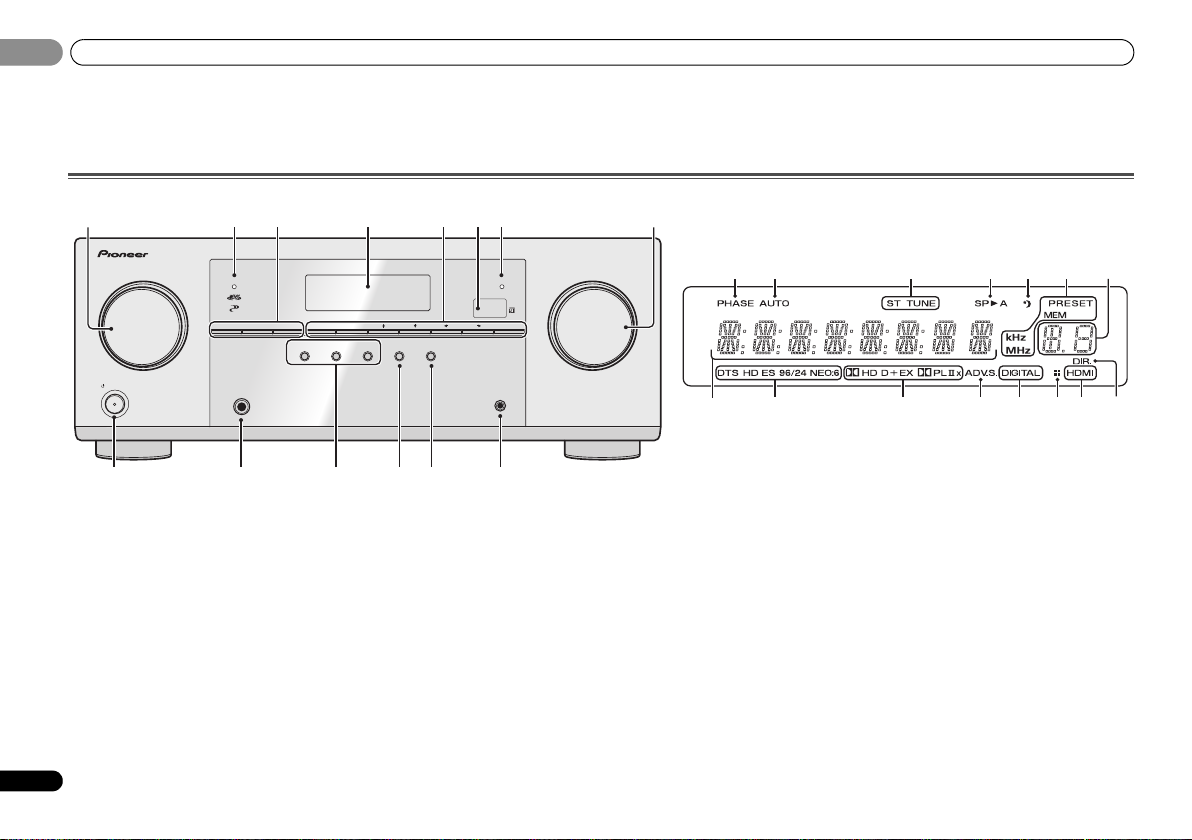
Front panel
1 INPUT SELECTOR dial
Selects an input source (page 21).
2 MCACC indicator
Lights when Acoustic Calibration EQ (page 26) is on
(Acoustic Calibration EQ is automatically set to on after the
Auto MCACC setup (page 19)).
3 Receiver control buttons
SPEAKERS – Use to change the speaker system on or off.
When the SP OFF is selected, no sound is output from the
speakers connected to this receiver.
DIMMER – Dims or brightens the display. The brightness
can be controlled in four steps.
DISPLAY – Switches the display of this unit. The listening
mode, sound volume, Pre Out setting or input name can
be checked by selecting an input source.
• The Pre Out setting may or may not be displayed,
6
depending on the input source you have selected.
En
4 Character display
See Display on page 7.
5 Tuner control buttons
BAND – Switches between AM, FM ST (stereo) and FM
MONO radio bands (page 24).
TUNER EDIT – Use with TUNE /, PRESET / and
ENTER to memorize and name stations for recall
(page 24).
TUNE / – Used to find radio frequencies (page 24).
PRESET / – Use to select preset radio stations
(page 24).
6 Remote sensor
Receives the signals from the remote control (see Operating
range of remote control on page 9).
7 HDMI indicator
Blinks when connecting an HDMI-equipped component;
lights when the component is connected (page 14).
8 MASTER VOLUME dial
9
STANDBY/ON
10 PHONES jack
Use to connect headphones. When the headphones are
connected, there is no sound output from the speakers. The
listening mode when the sound is heard from the headphone
can be selected only from PHONES SURR, STEREO or
STEREO ALC mode (S.R AIR mode can be also selected with
ADAPTER input).
11 Listening mode buttons
AUTO SURROUND/STREAM DIRECT – Switches
between Auto surround mode (page 25) and Stream
Direct playback (page 26).
Page 7

Controls and displays
English
Français
Español
01
01
ALC/STANDARD SURR – Press for standard decoding
and to switch between the modes of 2 Pro Logic II, 2
Pro Logic IIx, 2 Pro Logic IIz and NEO:6, and the Auto
level control stereo mode (page 25).
ADVANCED SURROUND – Switches between the
various surround modes (page 26).
12 SOUND RETRIEVER AIR
When the button is pressed, the input switches to ADAPTER
and the listening mode is automatically set to S.R AIR
(page 23).
13 SOUND RETRIEVER
Press to restore CD quality sound to compressed audio
sources (page 26).
14 PORTABLE/MCACC SETUP MIC jack
Use to connect an auxiliary component using a stereo minijack cable (page 18) or connect a microphone when
performing Auto MCACC setup (page 19).
Display
15 PHASE
Lights when the Phase Control is switched on (page 27).
16 AUTO
Lights when the Auto Surround feature is switched on
(page 25).
17 Tuner indicators
ST – Lights when a stereo FM broadcast is being received
in auto stereo mode (page 24).
TUNE – Lights when a normal broadcast channel.
PRESET – Shows when a preset radio station is registered
or called.
MEM – Blinks when a radio station is registered.
kHz/MHz – Lights when the character display is showing
the currently received AM/FM broadcast frequency.
18 Speaker indicators
Shows if the speaker system is on or not (page 6).
SPA means the speakers are switched on.
SP means the speakers are switched off.
19 Sleep timer indicator
Lights when the receiver is in sleep mode (page 8).
20 PRESET information or input signal indicator
Shows the preset number of the tuner or the input signal
type, etc.
21 Character display
Displays various system information.
22 DTS indicators
DTS – Lights when a source with DTS encoded audio
signals is detected.
HD – Lights when a source with DTS-EXPRESS or DTS-
HD encoded audio signals is detected.
ES – Lights to indicate DTS-ES decoding.
96/24 – Lights when a source with DTS 96/24 encoded
audio signals is detected.
NEO:6 – When one of the NEO:6 modes of the receiver is
on, this lights to indicate NEO:6 processing (page 25).
23 Dolby Digital indicators
2D – Lights when a Dolby Digital encoded signal is
detected.
2D+ – Lights when a source with Dolby Digital Plus
encoded audio signals is detected.
2HD – Lights when a source with Dolby TrueHD
encoded audio signals is detected.
EX – Lights to indicate Dolby Digital EX decoding.
2PLII(x) – Lights to indicate 2 Pro Logic II/2 Pro Logic
IIx decoding. Light will go off during 2 Pro Logic IIz
decoding (see Listening in surround sound on page 25 for
more on this).
24 ADV.S.
Lights when one of the Advanced Surround modes has been
selected (see Using the Advanced surround on page 26 for
more on this).
25 SIGNAL SELECT indicators
DIGITAL – Lights when a digital audio signal is selected.
Blinks when a digital audio signal is selected and
selected audio input is not provided.
HDMI – Lights when an HDMI signal is selected. Blinks
when an HDMI signal is selected and selected HDMI
input is not provided.
26 Up Mix/DIMMER indicator
Lights when the Up Mix function is set to ON (page 27). Also,
lights when DIMMER is set to off.
27 DIR.
Lights when the DIRECT or PURE DIRECT mode is switched
on (page 26).
7
En
Page 8
Controls and displays
BD DVD
INPUT SELECT
SOURCESLEEP
TV
CONTROL
DIMMER
TV
INPUT
1
4
7
MIDNIGHT
HDD
CH
RECEIVER
DVR/BDRCDCD-R
ADAPTER
TUNER
PORTABLE
VIDEO
SIGNAL SELS.RETRIEVER
BD MENU
ENTER
ADV SURR
AUTO/
DIRECT
VOL
+
10
2
5
8
SPEAKERS
LEV
LEV
SB CH
DISP
CLR
EQ
PHASE
DVD
3
6
9
0
ENTER
CH
CH
CH SELECT
VCR
SHIFT
MUTE
RETURN
AUDIO
PARAMETER
TUNER EDIT
TOOLS
MASTER
VOLUME
BAND
MENU
HOME
MENU
SETUP
TRE
BASS
TOP
MENU
RECEIVER
T
U
N
E
T
U
N
E
P
R
E
S
E
T
P
R
E
S
E
T
RECEIVER DTV/TV
ALC/
STANDARD
STEREO
1
2
12
13
15
14
16
17
3
4
6
5
7
8
9
10
11
18
RECEIVER
RECEIVER
RECEIVER
01
01
8
En
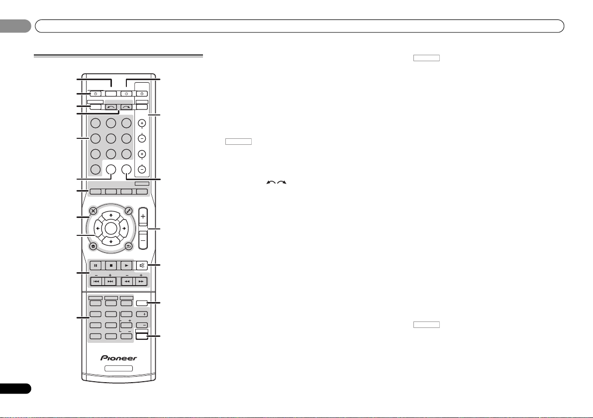
Remote control
As for operating other devices, the remote control codes for
the Pioneer products are preset. The settings cannot be
changed.
1 SLEEP
Press to change the amount of time before the receiver
switches into standby (30 min – 60 min – 90 min – Off). You
can check the remaining sleep time at any time by pressing
SLEEP once.
2
RECEIVER
Switches the receiver between standby and on.
3
Switches the remote to control the receiver (used to select
the white commands above the number buttons
(MIDNIGHT, etc)). Also use this button to set up surround
sound (page 30) or Audio parameters (page 28).
4 INPUT SELECT
Use to select the input source (page 21).
5 Input function buttons
Use to select the input source to this receiver (page 21). This
will enable you to control other Pioneer components with the
remote control.
6 S.RETRIEVER
Press to restore CD quality sound to compressed audio
sources (page 26).
7 Listening mode buttons
AUTO/DIRECT – Switches between Auto surround mode
(page 25) and Stream Direct playback (page 26).
STEREO – Press to select stereo playback (page 25).
ALC/STANDARD SURR – Press for standard decoding
and to switch between the modes of 2 Pro Logic II, 2
Pro Logic IIx, 2 Pro Logic IIz and NEO:6, and the Auto
level control stereo mode (page 25).
ADV SURR – Switches between the various surround
modes (page 26).
Press BD first to access:
BD MENU* – Displays the disc menu of Blu-ray Discs.
8 System Setup and component control buttons
The following button controls can be accessed after you have
selected the corresponding input function button (BD, DVD,
etc.).
Press first to access:
AUDIO PARAMETER – Use to access the Audio options
(page 28).
SETUP – Press to access the System Setup menu
(page 30).
RETURN – Confirm and exit the current menu screen.
Press BD, DVD or DVR/BDR first to access:
TOP MENU – Displays the disc ‘top’ menu of a Blu-ray
Disc/DVD.
HOME MENU – Displays the HOME MENU screen.
RETURN – Confirm and exit the current menu screen.
MENU – Displays the TOOLS menu of Blu-ray Disc player.
Press TUNER first to access:
TUNER EDIT – Memorizes stations for recall (page 24),
also used to change the name (page 24).
BAND – Switches between AM, FM ST (stereo) and FM
MONO radio bands (page 24).
9
///
Use the arrow buttons when setting up your surround sound
system (page 30). Also used to control Blu-ray Disc/DVD
menus/options.
Use TUNE / can be used to find radio frequencies and
PRESET / can be used to select preset radio stations
(page 24).
10 Component control buttons
The main buttons (, , etc.) are used to control a
component after you have selected it using the input function
buttons.
The controls above these buttons can be accessed after you
have selected the corresponding input function button (BD,
DVD, DVR/BDR and CD). These buttons also function as
described below.
(TUNE
/
, PRESET
/
), ENTER
Press first to access:
BASS –/+, TRE –/+ – Use to adjust Bass or Treble.
• These controls are disabled when the listening mode is
set to DIRECT or PURE DIRECT.
Page 9
Controls and displays
English
Français
Español
CAUTION
RECEIVER
30°
7 m (23 ft.)
30°
01
01
• When the front speaker is set at SMALL in the Speaker
Setting (or automatically via the Auto MCACC setup)
and the Crossover Network is set above 150 Hz, the
subwoofer channel level will be adjusted by pressing
BASS –/+ (page 31).
11 Number buttons and other component controls
Use the number buttons to directly select a radio frequency
(page 24) or the tracks on a CD, etc. There are other buttons
that can be accessed after is pressed. (For
example MIDNIGHT, etc.)
HDD*, DVD*, VCR* – These buttons switch between the
hard disk, DVD and VCR controls for HDD/DVD/VCR
recorders.
SB CH – Press to select ON, AUTO or OFF the surround
back channel (page 27).
CH SELECT – Press repeatedly to select a channel, then
use LEV +/– to adjust the level (page 31).
LEV +/– – Use to adjust the channel level.
EQ – Press to switch on/off Acoustic Calibration EQ
setting (page 26).
MIDNIGHT – Switches to Midnight or Loudness listening
(page 28).
SPEAKERS – Use to change the speaker system on or off.
When the SP OFF is selected, no sound is output from the
speakers connected to this receiver.
PHASE – Press to switch on/off Phase Control (page 27).
DIMMER – Dims or brightens the display. The brightness
can be controlled in four steps.
12
SOURCE
Turns on or off the power of the Pioneer DVD/DVR units when
BD, DVD, DVR/BDR or CD is selected using the input
function buttons.
13 TV CONTROL buttons
These buttons can control only be used with Pioneer TVs.
– Use to turn on/off the power of the TV.
INPUT – Use to select the TV input signal.
CH +/– – Use to select channels.
VOL +/– – Use to adjust the volume on your TV.
DTV/TV* – Switches between the DTV and analog TV
input modes for Pioneer TVs.
14 SIGNAL SEL
Press to select the audio input signal of the component to
play back (page 21).
15 MASTER VOLUME +/–
Use to set the listening volume.
16 MUTE
Mutes/unmutes the sound.
17 DISP
Switches the display of this unit. The listening mode, sound
volume, Pre Out setting or input name can be checked by
selecting an input source.
• The Pre Out setting may or may not be displayed,
depending on the input source you have selected.
18 SHIFT
Press to access the ‘boxed’ commands (above the buttons)
on the remote. These buttons are marked with an asterisk (*)
in this section.
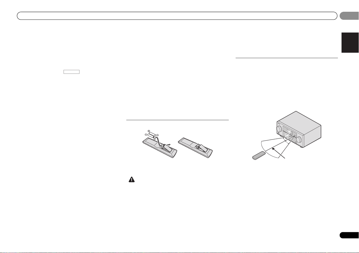
Loading the batteries
The batteries included with the unit are to check initial
operations; they may not last over a long period. We
recommend using alkaline batteries that have a longer life.
• Incorrect use of batteries may result in such hazards as
leakage and bursting. Observe the following precautions:
-
Never use new and old batteries together.
-
Insert the plus and minus sides of the batteries properly
according to the marks in the battery case.
-
Batteries with the same shape may have different
voltages. Do not use different batteries together.
-
When disposing of used batteries, please comply with
governmental regulations or environmental public
instruction’s rules that apply in your country or area.
-
Do not use or store batteries in direct sunlight or other
excessively hot place, such as inside a car or near a
heater. This can cause batteries to leak, overheat,
explode or catch fire. It can also reduce the life or
performance of batteries.
Operating range of remote control
The remote control may not work properly if:
• There are obstacles between the remote control and the
receiver’s remote sensor.
• Direct sunlight or fluorescent light is shining onto the
remote sensor.
• The receiver is located near a device that is emitting
infrared rays.
• The receiver is operated simultaneously with another
infrared remote control unit.
9
En
Page 10
Connecting your equipment
CAUTION
Important
120
120
SL
L
SW
C
R
SR
120
120
SL
L
SW
C
R
SR
SB
120
120
SL
L
FHL
FHR
SW
C
R
SR
90
90
60
SL
L
SW
C
R
SR
SBL
SBR
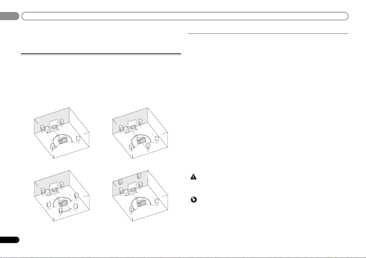
5.1 channel surround system:
7.1 channel surround
(Surround back) system:
a
7.1 channel surround
(Front height) system:
a
6.1 channel surround
(Surround back) system:
a
02
02
Chapter 2:
Connecting your equipment
Placing the speakers
By connecting the left and right front speakers (L/R), the center speaker (C), the left and right
surround speakers (
Further, by using an external amplifier, you can connect the left and right surround back
speakers (SBL/SBR) or the left and right front height speaker (FHL/FHR) to boost your system
up to a 7.1 ch surround system.
• You can also connect one surround back speaker (SB) and enjoy a 6.1 ch surround system.
To achieve the best possible surround sound, install your speakers as shown below.
10
En
a. This layout is available only when the additional amplifier is connected to the unit and the
surround back or front height speakers are connected to the amplifier. For details, see Connect
the surround back or front height speakers on page 11.
SL/SR
), and the subwoofer (SW), a 5.1 ch surround system can be enjoyed.
Hints on the speaker placement
Where you put your speakers in the room has a big effect on the quality of the sound. The
following guidelines should help you to get the best sound from your system.
• The subwoofer can be placed on the floor. Ideally, the other speakers should be at about
ear-level when you’re listening to them. Putting the speakers on the floor (except the
subwoofer), or mounting them very high on a wall is not recommended.
• For the best stereo effect, place the front speakers 2 m to 3 m (6 ft. to 9 ft.) apart, at equal
distance from the TV.
• If you’re going to place speakers around your CRT TV, use shielded speakers or place the
speakers at a sufficient distance from your CRT TV.
• If you’re using a center speaker, place the front speakers at a wider angle. If not, place
them at a narrower angle.
• Place the center speaker above or below the TV so that the sound of the center channel is
localized at the TV screen. Also, make sure the center speaker does not cross the line
formed by the leading edge of the front left and right speakers.
• It is best to angle the speakers towards the listening position. The angle depends on the
size of the room. Use less of an angle for bigger rooms.
• Surround and surround back speakers should be positioned 60 cm to 90 cm (2 ft. to 3 ft.)
higher than your ears and titled slight downward. Make sure the speakers don’t face each
other. For DVD-Audio, the speakers should be more directly behind the listener than for
home theater playback.
• If the surround speakers cannot be set directly to the side of the listening position with a
7.1-channel system, the surround effect can be enhanced by turning off the Up Mix
function (see Setting the Up Mix function on page 27).
• Try not to place the surround speakers farther away from the listening position than the
front and center speakers. Doing so can weaken the surround sound effect.
• Place the left and right front height speakers at least one meter directly above the left and
right front speakers.
• Make sure that all speakers are securely installed. This not only improves sound quality,
but also reduces the risk of damage or injury resulting from speakers being knocked over
or falling in the event of external shocks such as earthquakes.
• To connect the surround back or front height speakers, an additional amplifier is r equired.
Connect the additional amplifier to the PRE OUT SURR BACK/FRONT HEIGHT outputs of
this unit and connect the surround back or front height speakers to the additional amplifier
(see Connect the surround back or front height speakers on page 11).
Page 11
Connecting your equipment
English
Français
Español
CAUTION
10 mm
(3/8 in.)
12 3
10 mm
(3/8 in.)
LINE LEVEL
INPUT
ANALOG
RL
AUDIO IN
SPEAKER R SPEAKER L
Center
Surround right
Front right
Surround back or front height
channel amplifier
Front left
Subwoofer
Surround left
Right
Left
Surround back or
front height speakers
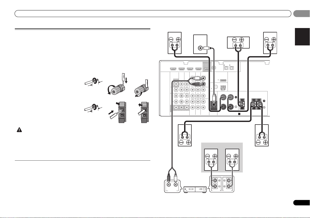
Connecting the speakers
The receiver will work with just two stereo speakers (the front speakers in the diagram) but
using at least three speakers is recommended, and a complete setup is best for surround
sound.
Make sure you connect the speaker on the right to the right (R) terminal and the speaker on
the left to the left (L) terminal. Also make sure the positive and negative (+/–) terminals on the
receiver match those on the speakers.
Be sure to complete all connections before connecting this unit to the AC power source.
Bare wire connections
Front speaker terminals:
1
Twist exposed wire strands together.
2
Loosen terminal and insert exposed wire.
3
Tighten terminal.
Center and surround speaker terminals:
1
Twist exposed wire strands together.
2
Push open the tabs and insert exposed
wire.
3
Release the tabs.
• These speaker terminals carry HAZARDOUS LIVE voltage. To prevent the risk of electric
shock when connecting or disconnecting the speaker cables, disconnect the power cord
before touching any uninsulated parts.
• Make sure that all the bare speaker wire is twisted together and inserted fully into the
speaker terminal. If any of the bare speaker wire touches the back panel it may cause the
power to cut off as a safety measure.
Connect the surround back or front height speakers
Connect the PRE OUT SURR BACK/FRONT HEIGHT outputs of the unit and additional
amplifier to add a surround back or front height speaker.
• The Pre Out setting must be set if the above connections are performed. Select
SURR.BACK if the surround back speaker is connected and HEIGHT if the front height
speaker is connected (If neither the surround back speaker nor the front height speaker is
connected, either setting will suffice) (see The Pre Out Setting on page 33).
• You can use the additional amplifier on the surround back channel pre-outs for a single
speaker as well. In this case plug the amplifier into the left (L (Single)) terminal only.
12 3
HDMI
DVR/BDR IN
VIDEO
MONITOR
OUT
DVR/
BDR
OUTINDVD IN
1
IN
(
)
DVD
ASSIGNABLE
2
IN
(
DVR/
)
BDR
MONITOR
OUT
YP
COMPONENT VIDEO
DVD IN
TV/SATINBD
B PR
BD IN VIDEO IN
AUDIO
DVR/BDR
IN
OUT
IN IN
IN
TV/SAT
CD-R/TAPE
BD
OUT
SURR BACK/
FRONT HEIGHT
L
(
Single
PRE OUT
R
CD
L
R
L
IN
R
DVD
)
(
OUTPUT 5 V
0.1 A MAX
FM
UNBAL
75
SUBWOOFER
PRE OUT
COAXIAL
1
IN
(CD)
ADAPTER PORT
)
AM LOOP
ASSIGNABLE
ANTENNA
Class 2 Wiring
OPTICAL
IN
IN
1
2
(
)
(
TV/SAT
CD-R/TAPE
FRONT
RL
SPEAKERS
ASSIGNABLE
)
A
CENTER
SURROUND
RL
02
02
11
En
Page 12
Connecting your equipment
Important
Note
Note
HDMI
02
02
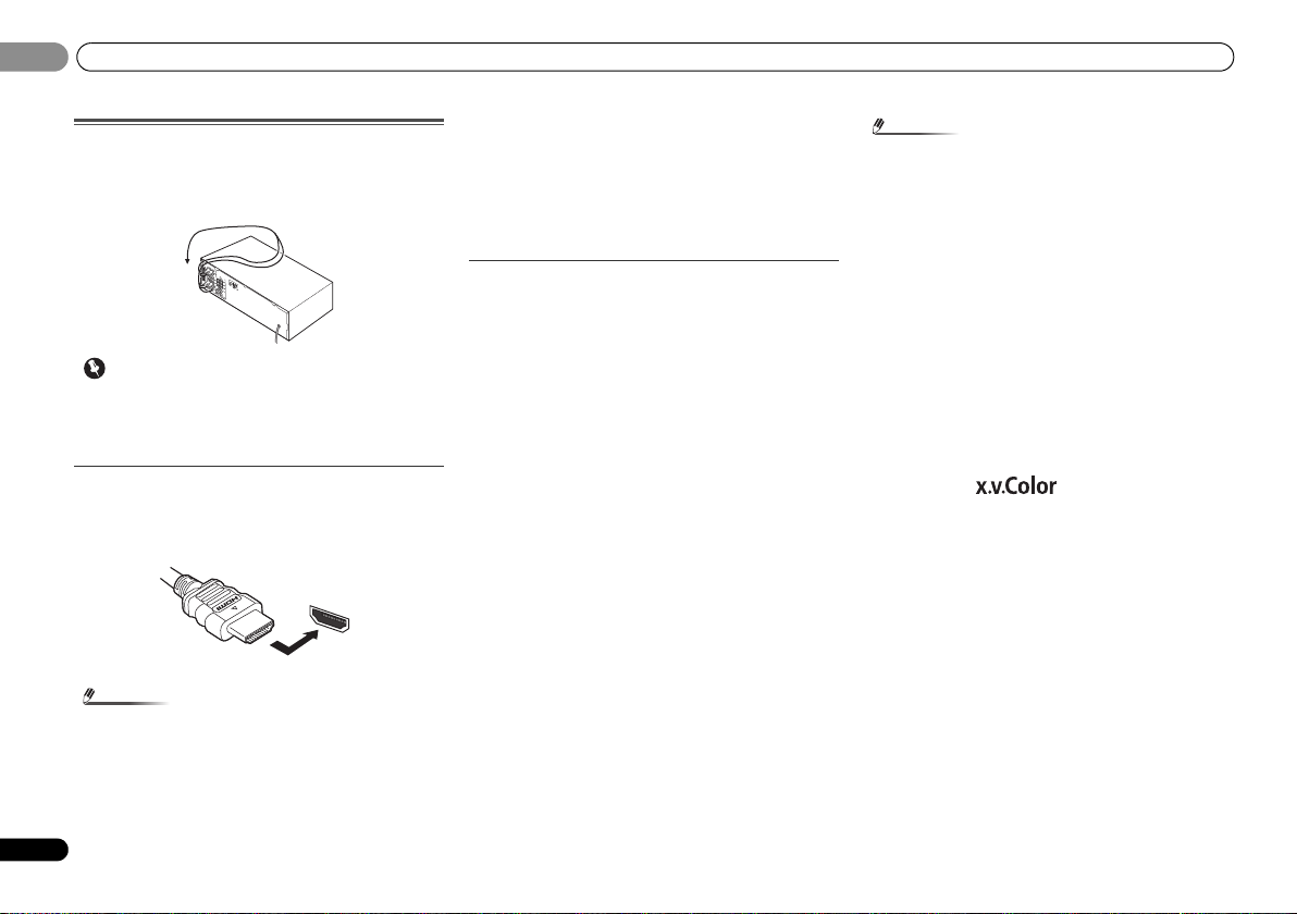
Making cable connections
Make sure not to bend the cables over the top of this unit (as
shown in the illustration). If this happens, the magnetic field
produced by the transformers in this unit may cause a
humming noise from the speakers.
• Before making or changing connections, switch off the
power and disconnect the power cord from the AC outlet.
• Before unplugging the power cord, switch the power into
standby.
HDMI cables
Both video and sound signals can be transmitted
simultaneously with one cable. If connecting the player and
the TV via this receiver, for both connections, use HDMI
cables.
Be careful to connect the terminal in the proper direction.
• Set the HDMI parameter in Setting the Audio options on
page 28 to THRU (THROUGH) and set the input signal in
Selecting the audio input signal on page 21 to HDMI, if you
want to hear HDMI audio output from your TV (no sound
will be heard from this receiver).
• If the video signal does not appear on your TV, try
adjusting the resolution settings on your component or
display. Note that some components (such as video game
units) have resolutions that may not be displayed. In this
case, use a (analog) composite connection.
• When the video signal from the HDMI is 480i, 480p, 576i
or 576p, Multi Ch PCM sound and HD sound cannot be
received.
About HDMI
The HDMI connection transfers uncompressed digital video,
as well as almost every kind of digital audio that the
connected component is compatible with, including DVDVideo, DVD-Audio, SACD, Dolby Digital Plus, Dolby TrueHD,
DTS-HD Master Audio (see below for limitations), Video CD/
Super VCD and CD.
This receiver incorporates High-Definition Multimedia
Interface (HDMI
This receiver supports the functions described below through
HDMI connections.
• Digital transfer of uncompressed video (contents
protected by HDCP (1080p/24, 1080p/60, etc.))
•3D signal transfer
• Deep Color signal transfer
• x.v.Color signal transfer
• Audio Return Channel
• Input of multi-channel linear PCM digital audio signals
(192 kHz or less) for up to 8 channels
• Input of the following digital audio formats:
– Dolby Digital, Dolby Digital Plus, DTS, High bitrate
audio (Dolby TrueHD, DTS-HD Master Audio), DVDAudio, CD, SACD (DSD 2 ch only), Video CD, Super VCD
• Synchronized operation with components using the
Control with HDMI function (see Control with HDMI
function on page 34)
®
) technology.
• Use a High Speed HDMI® cable. If HDMI cable other than
a High Speed HDMI
properly.
• When an HDMI cable with a built-in equalizer is
connected, it may not operate properly.
• 3D, Deep Color, x.v.Color signal transfer and Audio
Return Channel are only possible when connected to a
compatible component.
• HDMI format digital audio tr ansmissions require a longer
time to be recognized. Due to this, interruption in the
audio may occur when switching between audio formats
or beginning playback.
• Turning on/off the device connected to this unit’s HDMI
OUT terminal during playback, or disconnecting/
connecting the HDMI cable during playback, may cause
noise or interrupted audio.
HDMI, the HDMI Logo and High-Definition Multimedia
Interface are trademarks or registered trademarks of HDMI
Licensing, LLC in the United States and other countries.
“x.v.Color” and are trademarks of Sony
Corporation.
®
cable is used, it may not work
12
En
Page 13
Connecting your equipment
English
Français
Español
Note
L
R
AUDIO
White (Left)
Red (Right)
COAXIAL
IN
OPTICAL
IN
Coaxial digital
audio cable
Optical cable
Yellow
Y
P
B
P
R
COMPONENT VIDEO
Green (Y)
Red (PR)
Blue (PB)
Terminal for connection with source device
Terminal for connection with TV monitor
Playback
component
TV
The OSD will
not appear.
Video signals can be output.
02
02
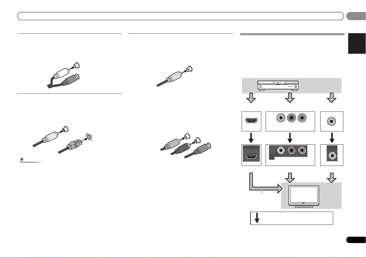
Analog audio cables
Use stereo RCA phono cables to connect analog audio
components. These cables are typically red and white, and
you should connect the red plugs to R (right) terminals and
white plugs to L (left) terminals.
Digital audio cables
Commercially available coaxial digital audio cables or optical
cables should be used to connect digital components to this
receiver.
• When connecting optical cables, be careful when
inserting the plug not to damage the shutter protecting
the optical socket.
• When storing optical cable, coil loosely. The cable may be
damaged if bent around sharp corners.
• You can also use a standard RCA video cable for coaxial
digital connections.
Video cables
Standard RCA video cables
These cables are the most common type of video connection
and are used to connect to the composite video terminals.
The yellow plugs distinguish them from cables for audio.
VIDEO
Component video cables
Use component video cables to get the best possible color
reproduction of your video source. The color signal of the TV
is divided into the luminance (Y) signal and the color (P
P
R) signals and then output. In this way, interference between
the signals is avoided.
B and
About video outputs connection
This receiver is not loaded with a video converter. When you
use component video cables or HDMI cables for connecting
to the input device, the same cables should be used for
connecting to the TV.
The signals input from the analog (composite and
component) video inputs of this unit will not be output from
the HDMI OUT.
IN
HDMI
OUT
HDMI
IN
YPBP
COMPONENT VIDEO
MONITOR
OUT
YPBP
COMPONENT VIDEO
R
R
IN
VIDEO
MONITOR
OUT
VIDEO
13
En
Page 14

Connecting your equipment
Important
VIDEO
MONITOR
OUT
HDMI
VIDEO
COMPONENT VIDEO
DVR/
BDR
L
R
R
L
YP
BPR
COAXIAL
AUDIO
PRE OUT
SPEAKERS
ANTENNA
OPTICAL
ASSIGNABLE
ASSIGNABLE
ASSIGNABLE
OUT
A
DVR/BDR
OUT
CD-R/TAPE
SURR BACK/
FRONT HEIGHT
L
R
PRE OUT
(
Single
)
IN
(CD)
1
SUBWOOFER
IN IN
CD
MONITOR
OUT
TV/SATINBD
IN
OUTINDVD IN
IN
TV/SAT
BD
IN
DVD
(
DVD
)
IN
1
MONITOR
OUT
(
DVR/
BDR
)
IN
2
DVR/BDR IN
DVD IN
BD IN VIDEO IN
(
TV/SAT
)
IN
1
(
CD-R/TAPE
)
IN
2
FM
UNBAL
75
(
OUTPUT 5 V
0.1 A MAX
)
ADAPTER PORT
AM LOOP
FRONT
RL
CEN
Class 2 Wiring
VIDEO IN
HDMI IN
HDMI OUT
RL
DIGITAL AUDIO OUTANALOG AUDIO OUT
OPTICAL
Select one
HDMI/DVI-compatible TV
HDMI/DVI-compatible
Blu-ray Disc player
This connection is
necessary in order to
see the OSD of the
unit on the TV.
If the TV does not support
the HDMI Audio Return
Channel function, this
connection is required to
listen to the TV sound over
the receiver.
02
02
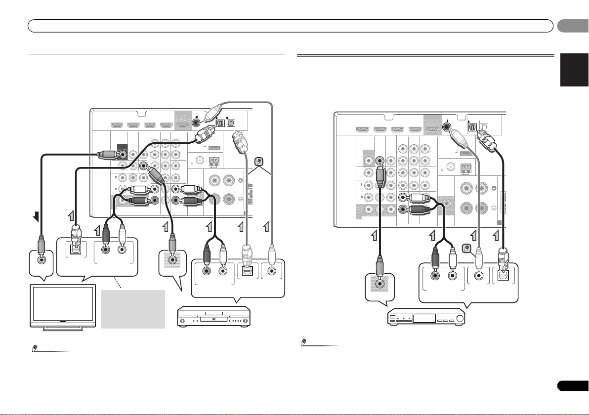
Connecting a TV and playback components
Connecting using HDMI
If you have an HDMI or DVI (with HDCP) equipped component (Blu-ray Disc player, etc.), you
can connect it to this receiver using a commercially available HDMI cable.
If the TV and playback components support the Control with HDMI feature, the convenient
Control with HDMI functions can be used (see Control with HDMI function on page 34).
• The following connection/setting is required to listen to the sound of the TV over this
receiver.
-
If the TV does not support the HDMI Audio Return Channel function, connect the receiver
and TV with audio cables (as shown).
-
If the TV supports the HDMI Audio Return Channel function, the sound of the TV is input
to the receiver via the HDMI terminal, so there is no need to connect an audio cable. In
this case, set ARC at HDMI Setup to ON (see HDMI Setup on page 34).
• If the receiver is connected to a TV using an HDMI cable, the on-screen display (OSD) will
not be displayed. Be sure to use a standard RCA analog video cable to connect. In this
case, switch the TV input to analog to see the OSD screen (for setup, etc.) on the TV.
• When the Control with HDMI function is ON and the receiver is connected to a compatible
TV with an HDMI cable, and you switch the input of the TV to composite or component, the
input of the receiver may automatically switch to TV/SAT. If this happens, switch the
receiver’s input back to the original input, or turn OFF the Control with HDMI function (see
HDMI Setup on page 34).
14
En
Page 15
Connecting your equipment
English
Français
Español
Note
Note
T
RL
DIGITAL AUDIO OUT ANALOG AUDIO OUT
OPTICAL
RL
DIGITAL AUDIO OUTANALOG AUDIO OUT
OPTICAL COAXIAL
VIDEO IN
VIDEO OUT
Select one
TV
DVD player
Select one
This connection is
required in order to
listen to the sound of
the TV over the
receiver.
T
RL
DIGITAL AUDIO OUTANALOG AUDIO OUT
OPTICALCOAXIAL
VIDEO OUT
Select one
Set-top box, etc.
02
02
Connecting your component with no HDMI terminal
This diagram shows connections of a TV and DVD player (or other playback component) with
no HDMI terminal to the receiver.
• If both TV and player has a component video jacks, you can connect these too. See Using
the component video jacks on page 16 for more on this.
COAXIAL
CD-R/TAPE
BD
OUT
SURR BACK/
FRONT HEIGHT
L
(
Single
PRE OUT
R
CD
L
R
L
IN
R
DVD
)
(
OUTPUT 5 V
0.1 A MAX
FM
UNBAL
75
SUBWOOFER
PRE OUT
1
IN
(CD)
ADAPTER PORT
)
AM LOOP
ASSIGNABLE
ANTENNA
Class 2 Wiring
IN
IN
1
2
(
)
(
TV/SAT
CD-R/TAPE
FRONT
RL
SPEAKERS
HDMI
DVR/BDR IN
VIDEO
MONITOR
OUT
DVR/
BDR
OUTINDVD IN
1
IN
(
)
DVD
ASSIGNABLE
2
IN
(
DVR/
)
BDR
MONITOR
OUT
YP
COMPONENT VIDEO
DVD IN
TV/SATINBD
BPR
BD IN VIDEO IN
AUDIO
DVR/BDR
IN
OUT
IN IN
IN
TV/SAT
• In order to listen to the audio from the DVD player that is connected to this receiver using
an optical cable or a coaxial cable, first, switch to the DVD input, then press SIGNAL SEL
to choose the audio signal O2 (OPTICAL2) or C1 (COAXIAL1) (see Selecting the audio input
signal on page 21).
OPTICAL
ASSIGNABLE
)
Connecting a satellite receiver or other digital set-top box
Satellite and cable receivers, and terrestrial digital TV tuners are all examples of so-called ‘settop boxes’.
• If the set-top box or video component also has an HDMI or a component video output, you
can connect this too. See Connecting using HDMI on page 14 or Using the component
video jacks on page 16 for more on this.
COAXIAL
CD-R/TAPE
BD
OUT
SURR BACK/
FRONT HEIGHT
L
(
Single
PRE OUT
R
CD
L
R
L
IN
R
DVD
)
(
OUTPUT 5 V
0.1 A MAX
FM
UNBAL
75
SUBWOOFER
PRE OUT
1
IN
(CD)
ADAPTER PORT
)
AM LOOP
ASSIGNABLE
ANTENNA
Class 2 Wiring
OPTICAL
IN
IN
1
2
ASSIGNABLE
(
)
(
TV/SAT
CD-R/TAPE
FRONT
RL
SPEAKERS
)
CEN
A
DVD IN
DVR/BDR IN
HDMI
VIDEO
MONITOR
DVR/
CEN
A
• In order to listen to the audio from the source component that is connected to this receiver
using a coaxial cable, first, switch to the TV/SAT, then press SIGNAL SEL to choose the
audio signal C1 (COAXIAL1) (see Selecting the audio input signal on page 21).
BDR
1
IN
(
)
DVD
ASSIGNABLE
2
IN
(
DVR/
)
BDR
MONITOR
OUT
COMPONENT VIDEO
TV/SATINBD
OUT
OUTINDVD IN
YP
BPR
BD IN VIDEO IN
AUDIO
DVR/BDR
IN
OUT
IN IN
IN
TV/SAT
15
En
Page 16
Connecting your equipment
Note
Important
T
Select one
HDD/DVD recorder, Blu-ray
Disc recorder, etc.
C
FRONT HEIGHT
Y
P
B
PR
COMPONENT VIDEO IN
Y
P
B
PR
COMPONENT VIDEO OUT
DVD player
TV
02
02
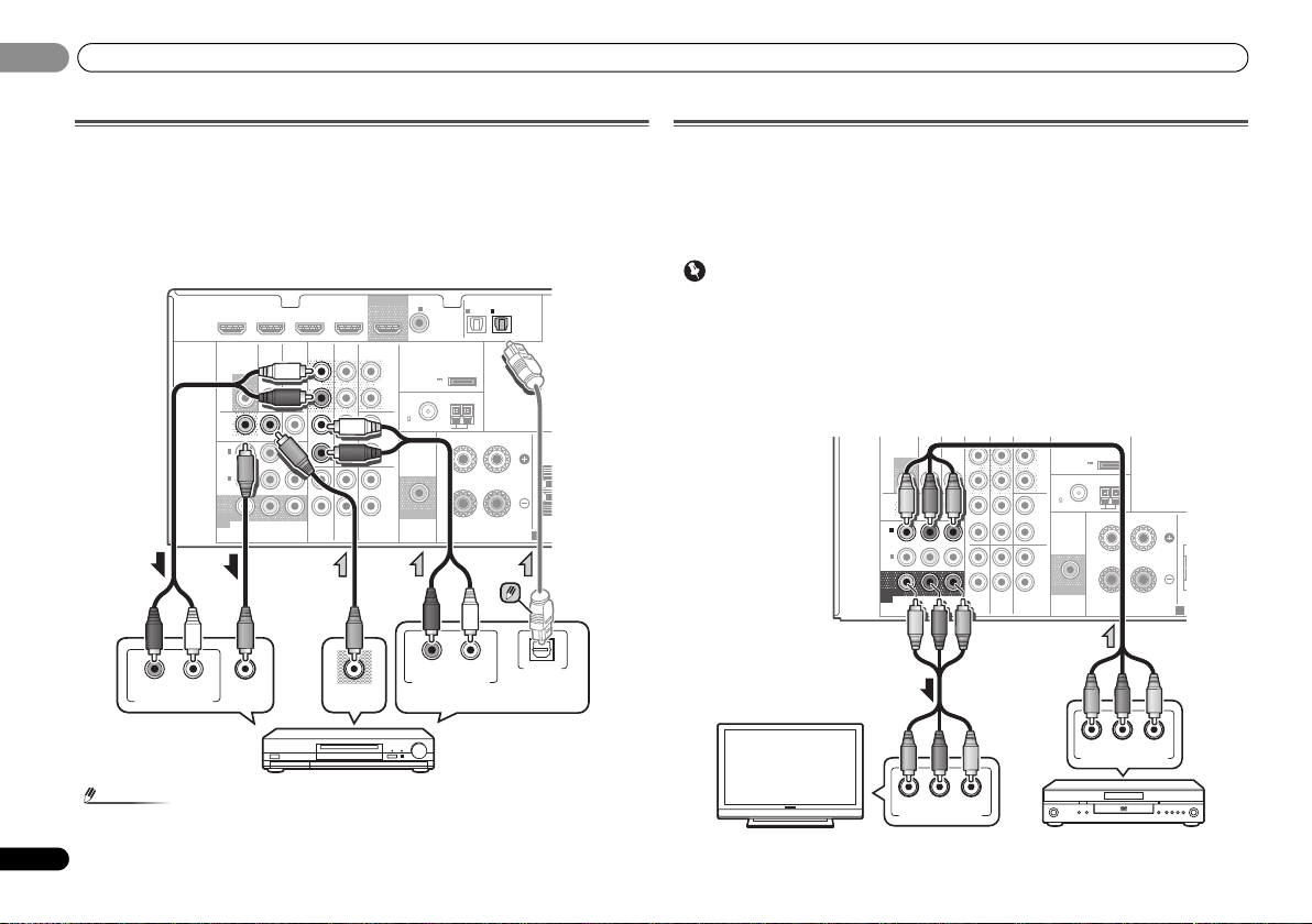
Connecting an HDD/DVD recorder, Blu-ray Disc recorder and other
video sources
This receiver has audio/video inputs and outputs suitable for connecting analog or digital
video recorders, including HDD/DVD recorders and Blu-ray Disc recorders.
• Only the signals that are input to the VIDEO IN terminal can be output from the VIDEO OUT
terminal.
• Audio signals that are input through the digital terminal will not be out put from the analog
terminal.
COAXIAL
CD-R/TAPE
BD
VIDEO OUT
OUT
SURR BACK/
FRONT HEIGHT
L
(
Single
PRE OUT
R
CD
L
R
L
IN
R
DVD
IN
(CD)
)
(
OUTPUT 5 V
0.1 A MAX
FM
UNBAL
75
SUBWOOFER
PRE OUT
1
ASSIGNABLE
ADAPTER PORT
)
ANTENNA
AM LOOP
Class 2 Wiring
RL
OPTICAL
IN
IN
1
2
(
)
(
TV/SAT
CD-R/TAPE
FRONT
RL
SPEAKERS
DIGITAL AUDIO OUTANALOG AUDIO OUT
ASSIGNABLE
)
CEN
A
OPTICAL
HDMI
RL
ANALOG AUDIO IN
DVR/BDR IN
VIDEO
MONITOR
OUT
DVR/
BDR
OUTINDVD IN
1
IN
(
)
DVD
ASSIGNABLE
2
IN
(
DVR/
)
BDR
MONITOR
OUT
YP
COMPONENT VIDEO
VIDEO IN
DVD IN
TV/SATINBD
BPR
BD IN VIDEO IN
AUDIO
DVR/BDR
IN
OUT
IN IN
IN
TV/SAT
Using the component video jacks
Component video should deliver superior picture quality when compared to composite video.
A further advantage (if your source and TV are both compatible) is progressive-scan video,
which delivers a very stable, flicker-free picture. See the manuals that came with your TV and
source component to check whether they are compatible with progressive-scan video.
• For the audio connection, refer to Connecting your component with no HDMI terminal on
page 15.
• If you connect any source component to the receiver using a component video input, you
must also have your TV connected to this receiver’s COMPONENT VIDEO MONITOR OUT
jacks.
• If necessary, assign the component video inputs to the input source you’ve connected.
This only needs to be done if you didn’t connect according to the following defaults:
-
COMPONENT VIDEO IN 1: DVD
-
COMPONENT VIDEO IN 2: DVR/BDR
See The Input Assign menu on page 32 for more on this.
MONITOR
DVR/
BDR
1
IN
(
)
DVD
ASSIGNABLE
2
IN
(
DVR/
)
BDR
MONITOR
OUT
COMPONENT VIDEO
TV/SATINBD
OUT
OUTINDVD IN
B PR
YP
DVR/BDR
IN
OUT
IN IN
IN
TV/SAT
D-R/TAPE
BD
ADAPTER PORT
L
(
)
Single
(
OUTPUT 5 V
)
PRE OUT
0.1 A MAX
R
ANTENNA
FM
UNBAL
CD
75
L
AM LOOP
FRONT
SUBWOOFER
PRE OUT
RL
Class 2 Wiring
R
L
IN
R
DVD
SPEAKERS
C
A
• In order to listen to the audio from the source component that is connected to this receiver
using an optical cable, first, switch to the DVR/BDR input, then press SIGNAL SEL to
choose the audio signal O2 (OPTICAL2) (see Selecting the audio input signal on page 21).
16
En
Page 17
Connecting your equipment
English
Français
Español
Note
Important
HDMI
VIDEO
COMPONENT VIDEO
DVR/
BDR
L
R
R
L
YP
B PR
COAXIAL
AUDIO
PRE OUT
SPEAKERS
ANTENNA
OPTICAL
ASSIGNABLE
ASSIGNABLE
ASSIGNABLE
OUT
A
DVR/BDR
OUT
CD-R/TAPE
SURR BACK/
FRONT HEIGHT
L
R
PRE OUT
(
Single
)
IN
(CD)
1
SUBWOOFER
IN IN
CD
MONITOR
OUT
TV/SATINBD
IN
OUTINDVD IN
IN
TV/SAT
BD
IN
DVD
(
DVD
)
IN
1
MONITOR
OUT
(
DVR/
BDR
)
IN
2
DVR/BDR IN
DVD IN
BD IN VIDEO IN
(
TV/SAT
)
IN
1
(
CD-R/TAPE
)
IN
2
FM
UNBAL
75
(
OUTPUT 5 V
0.1 A MAX
)
ADAPTER PORT
AM LOOP
FRONT
RL
CEN
Class 2 Wiring
REC
RL
DIGITAL AUDIO OUTANALOG AUDIO OUT
RL
ANALOG AUDIO IN
OPTICALCOAXIAL
Select one
CD-R, MD, DAT,
Tape recorder, etc.
HDMI
VIDEO
COMPONENT VIDEO
DVR/
BDR
L
R
R
L
YP
BPR
COAXIAL
AUDIO
PRE OUT
SPEAKE
ANTENNA
OP
ASSIGNABLE
ASSIGNABLE
ASS
OUT
DVR/BDR
OUT
CD-R/TAPE
SURR BACK/
FRONT HEIGHT
L
R
PRE OUT
(
Single
)
IN
(CD)
1
SUBWOOFER
IN IN
CD
MONITOR
OUT
TV/SATINBD
IN
OUTINDVD IN
IN
TV/SAT
BD
IN
DVD
(
DVD
)
IN
1
MONITOR
OUT
(
DVR/
BDR
)
IN
2
DVR/BDR IN
DVD IN
BD IN VIDEO IN
(
TV/SAT
)
IN
1
(
CD-R/TAPE
IN
2
FM
UNBAL
75
(
OUTPUT 5 V
0.1 A MAX
)
ADAPTER PORT
AM LOOP
FRONT
RL
Class 2 Wiring
Bluetooth® ADAPTER
ANTENNA
FM
UNBAL
75
AM LOOP
2
1
3
4
fig. a
fig. b
02
02
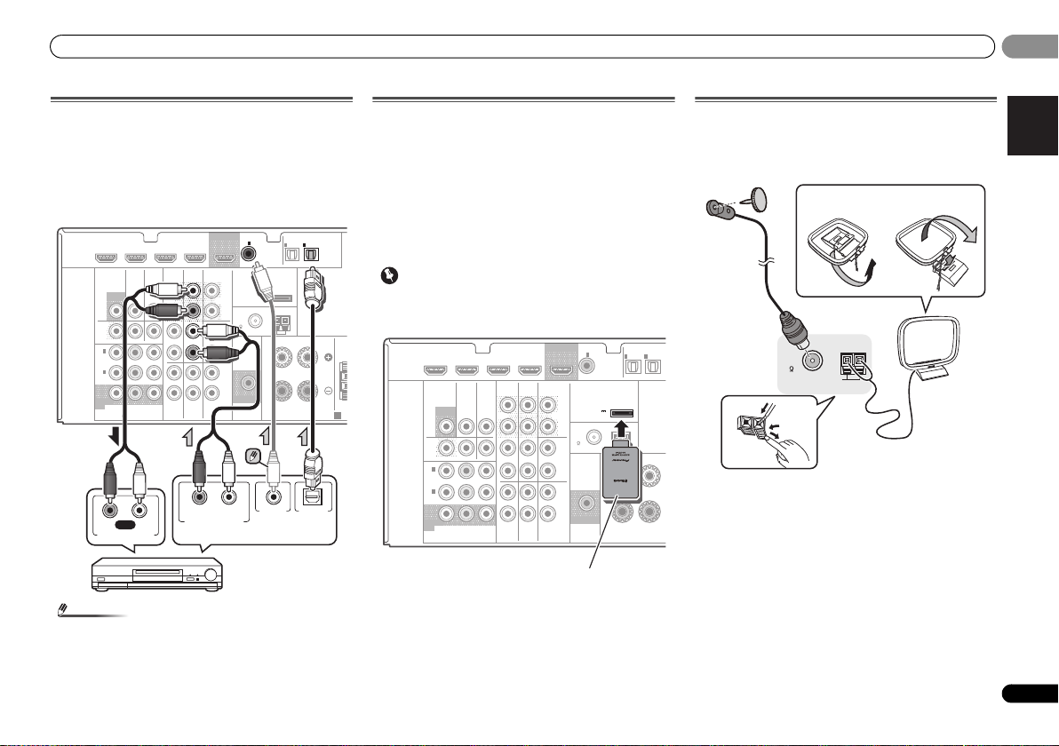
Connecting other audio components
The number and kind of connections depends on the kind of
component you’re connecting. Follow the steps below to
connect a CD-R, MD, DAT, tape recorder or other audio
component.
• Note that yo u must connect digital components to analog
audio jacks if you want to record to/from digital
components (like an MD) to/from analog components.
• In order to listen to the audio from the CD player that is
connected to this receiver using a coaxial cable, first,
switch to the CD-R input, then press SIGNAL SEL to
choose the audio signal C1 (COAXIAL1) (see Selecting the
audio input signal on page 21).
Connecting optional
When the Bluetooth ADAPTER (Pioneer Model No. AS-BT100
or AS-BT200) is connected to this unit, a product equipped
with Bluetooth wireless technology (portable cell phone,
digital music player, etc.) can be used to listen to music
wirelessly.
Connect a
terminal on the rear panel.
• For instructions on playing the Bluetooth wireless
technology device, see Pairing the Bluetooth ADAPTER
and Bluetooth wireless technology device on page 23.
• Do not move the receiver with the Bluetooth ADAPTER
connected. Doing so could cause damage or faulty
contact.
Bluetooth
Bluetooth® ADAPTER
ADAPTER to the ADAPTER PORT
Connecting antennas
Connect the AM loop antenna and the FM wire antenna as
shown below. To improve reception and sound quality,
connect external antennas (see Using external antennas
below).
1
Push open the tabs, then insert one wire fully into each
terminal, then release the tabs to secure the AM antenna
wires.
2
Fix the AM loop antenna to the attached stand.
To fix the stand to the antenna, bend in the direction
indicated by the arrow (fig. a) then clip the loop onto the
stand (fig. b).
3
Place the AM antenna on a flat surface and in a direction
giving the best reception.
4
Connect the FM wire antenna into the FM antenna
socket.
For best results, extend the FM antenna fully and fix to a wall
or door frame. Don’t drape loosely or leave coiled up.
17
En
Page 18
Connecting your equipment
CAUTION
Note
F connector
ANTENNA
AM LOOP
Outdoor
antenna
5 m to 6 m
(16 ft. to 20 ft.)
Indoor antenna
(vinyl-coated wire)
This receiver
Digital audio player, etc.
02
02
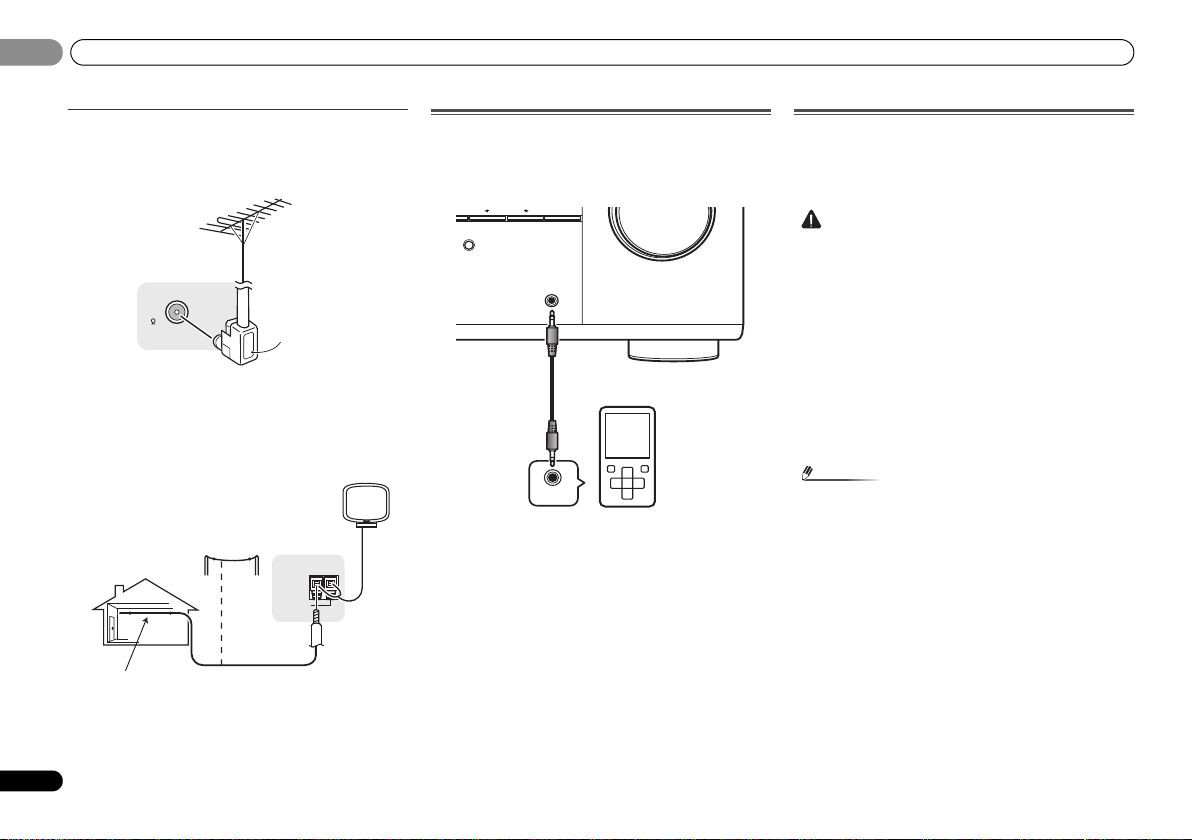
Using external antennas
To improve FM reception
Use an F connector (not supplied) to connect an external FM
antenna.
ANTENNA
FM
UNBAL
75
To improve AM reception
Connect a 5 m to 6 m (16 ft. to 20 ft.) length of vinyl-coated
wire to the AM antenna terminal without disconnecting the
supplied AM loop antenna.
For the best possible reception, suspend horizontally
outdoors.
Connecting to the front panel audio mini jack
Front audio connections are accessed via the front panel
using the INPUT SELECTOR or PORTABLE button on the
remote control. Use a stereo mini-jack cable to connect a
digital audio player, etc.
SOUND
RETRIEVER
PRESET ENTER
PORTABLE /
MCACC
SETUP MIC
AUDIO OUT
MASTER
VOLUME
Plugging in the receiver
Only plug in after you have connected all your components to
this receiver, including the speakers.
Plug the AC power cord into a convenient AC power
outlet.
• Handle the power cord by the plug part. Do not pull out
the plug by tugging the cord, and never touch the power
cord when your hands are wet, as this could cause a short
circuit or electric shock. Do not place the unit, a piece of
furniture, or other object on the power cord or pinch the
cord in any other way. Never make a knot in the cord or tie
it with other cables. The power cords should be routed so
that they are not likely to be stepped on. A damaged
power cord can cause a fire or give you an electric shock.
Check the power cord once in a while. If you find it
damaged, ask your nearest Pioneer authorized
independent service company for a replacement.
• The receiver should be disconnected by removing the
mains plug from the wall socket when not in regular use,
e.g., when on vacation.
• After this receiver is connected to an AC outlet, a 2
second to 10 second HDMI initialization process begins.
You cannot carry out any operations during this process.
The HDMI indicator in the front panel display blinks
during this process, and you can turn on this receiver
once it has stopped blinking. When you set the Control
with HDMI to OFF, you can skip this process. For details
about the Control with HDMI feature, see Control with
HDMI function on page 34.
18
En
Page 19
Basic Setup
English
Français
Español
CAUTION
Important
INPUT SELECT
SOURCESLEEP
TV
CONTROL
INPUT
RECEIVER
RECEIVER
BD DVD TV
DTV/TV
ENTER
MUTE
RETURN
PARAMETER
TOOLS
VOLUME
BAND
MENU
TOP
MENU
T
U
N
E
T
U
N
E
P
R
E
S
E
T
P
R
E
S
E
T
HOME
MENU
SETUP
Tripod
Microphone
RECEIVER
System Setup
1.Auto MCACC
2.Manual SP Setup
3.Input Assign
4.Pre Out Setting
5.HDMI Setup
6.Auto Power Down
7.FL Demo Mode
Return
Chapter 3:
Basic Setup
Canceling the demo display
The display on the front panel shows various information
(demo displays) when the receiver is not operating.
You can turn off the demo display. For details, see The FL
Demo Mode menu on page 33.
• The demo mode is canceled automatically when the Auto
MCACC setup is performed (see below).
Automatically setting up for surround sound
(MCACC)
The Auto Multi-Channel Acoustic Calibration (MCACC) setup
measures the acoustic characteristics of your listening area,
taking into account ambient noise, speaker size and
distance, and tests for both channel delay and channel level.
After you have set up the microphone provided with your
system, the receiver uses the information from a series of test
tones to optimize the speaker settings and equalization for
your particular room.
• The test tones used in the Auto MCACC setup are output
at high volume.
• The OSD will not appear if you have connected using the
HDMI output to your TV. Use composite or connections
for system setup.
• The Auto MCACC setup will overwrite any existing
speaker settings you’ve made.
• If you connected either the surround back speaker or the
front height speaker, make sure that the Pre Out setting
is correctly set before performing the Auto MCACC setup
(see page 33). (Here is an explanation using the OSD
screen for a surround back speaker connection.)
1
Switch on the receiver and your TV.
2
Switch the TV input to the input that connects this
receiver to the TV through the corresponding composite or
component cable.
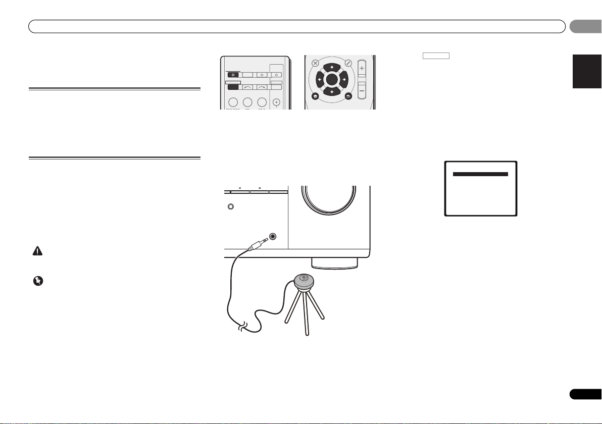
3
Connect the microphone to the MCACC SETUP MIC jack
on the front panel.
Make sure there are no obstacles between the speakers and
the microphone.
If you have a tripod, use it to place the microphone so that it’s
about ear level at your normal listening position. Otherwise,
place the microphone at ear level using a table or a chair.
SOUND
RETRIEVER
PRESET ENTER
PORTABLE /
MCACC
SETUP MIC
MASTER
VOLUME
4
Press on the remote control, then press the
SETUP button.
The System Setup menu appears on your TV. Use ///
and ENTER on the remote control to navigate through the
screens and select menu items. Press RETURN to exit the
current menu.
• Press SETUP at any time to exit the System Setup menu.
If you cancel the Auto MCACC setup at any time, the
receiver automatically exits and no settings will be made.
• The screensaver automatically starts after three minutes
of inactivity.
5
Select ‘Auto MCACC’ from the System Setup menu, then
press ENTER.
• MIC IN blinks when the microphone is not connected to
MCACC SETUP MIC jack.
Try to be as quiet as possible after pressing ENTER. The
system outputs a series of test tones to establish the ambient
noise level.
6
Follow the instructions on-screen.
• Make sure the microphone is connected.
• Make sure the subwoofer is on and the volume is turned
up.
• When using surround back or front height speakers, turn
on the power to the amplifier to which the surround back
or front height speakers are connected, and adjust the
sound level to the desired level.
• See below for notes regarding background noise and
other possible interference.
03
03
19
En
Page 20
Basic Setup
Note
1.Auto MCACC
Now Analyzing
Environment Check
Ambient Noise
Speaker YES/NO
Return
1.Auto MCACC
Now Analyzing
Surround Analyzing
Speaker System
Speaker Distance
Channel Level
Acoustic Cal EQ
Return
03
03
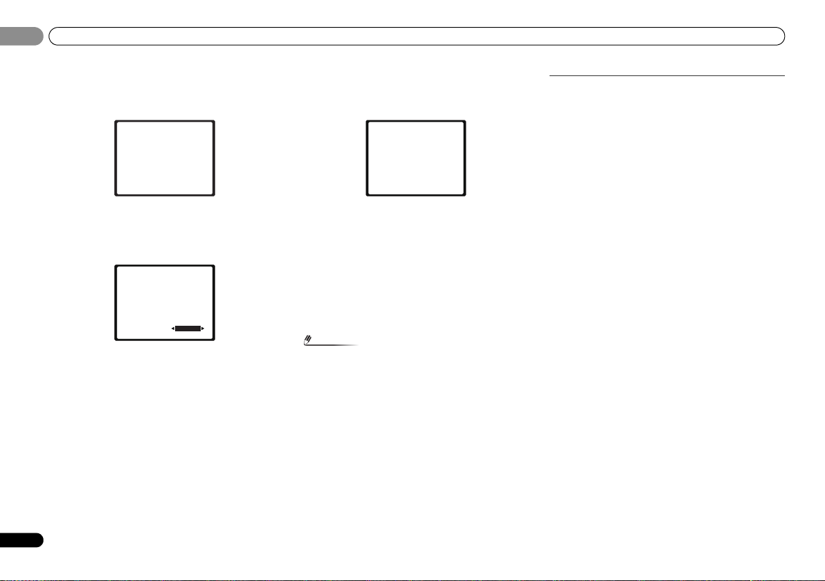
7
Wait for the test tones to finish.
A progress report is displayed on-screen while the receiver
outputs test tones to determine the speakers present in your
setup. Try to be as quiet as possible while it’s doing this.
• For correct speaker settings, do not adjust the volume
during the test tones.
8
Confirm the speaker configuration.
The configuration shown on-screen should reflect the actual
speakers you have.
1.Auto MCACC
Check!
[ YES ]
Front
[ YES ]
Center
[ YES ]
Surr
[YESx2]
Surr. Back
[ YES ]
Subwoofer
10:Next
• With error messages (such as Too much ambient noise)
select RETRY after checking for ambient noise (see Other
problems when using the Auto MCACC setup below).
If the speaker configuration displayed isn’t correct, use /
to select the speaker and / to change the setting. When
you’re finished, go to the next step.
If you see an error message (ERR) in the right side column,
there may be a problem with the speaker connection. If
selecting RETRY doesn’t fix the problem, turn off the power
and check the speaker connections.
OK
Return
9
Make sure ‘OK’ is selected, then press ENTER.
If the screen in step 7 is left untouched for 10 seconds and
ENTER is not pressed in step 8, the Auto MCACC setup will
start automatically as shown.
A progress report is displayed on-screen while the receiver
outputs more test tones to determine the optimum receiver
settings for channel level, speaker distance, and Acoustic
Calibration EQ.
Again, try to be as quiet as possible while this is happening.
It may take 1 to 3 minutes.
10
The Auto MCACC setup has finished! You return to the
System Setup menu.
The settings made in the Auto MCACC setup should give you
excellent surround sound from your system, but it is also
possible to adjust these settings manually using the System
Setup menu (starting on page 30).
• Depending on the characteristics of your room,
sometimes identical speakers with cone sizes of around
12 cm (5 inches) will end up with different size settings.
You can correct the setting manually using the Speaker
Setting on page 30.
• The subwoofer distance setting may be farther than the
actual distance from the listening position. This setting
should be accurate (taking delay and room
characteristics into account) and generally does not need
to be changed.
Other problems when using the Auto MCACC
setup
If the room environment is not optimal for the Auto MCACC
setup (too much background noise, echo off the walls,
obstacles blocking the speakers from the microphone) the
final settings may be incorrect. Check for household
appliances (air conditioner, fridge, fan, etc.), that may be
affecting the environment and switch them off if necessary. If
there are any instructions showing in the front panel display,
please follow them.
• Some older TVs may interfere with the operation of the
microphone. If this seems to be happening, switch off the
TV when doing the Auto MCACC setup.
20
En
Page 21

Basic playback
English
Français
Español
Note
Note
INPUT SELECT
SOURCESLEEP
TV
CONTROL
INPUT
RECEIVER
CH
VOL
RECEIVER
BD DVD TV
DVR/BDRCDCD-R
ADAPTER
TUNER
PORTABLE
VIDEO
SIGNAL SELS.RETRIEVER
DTV/TV
ENTER
ADV SURR
AUTO/
DIRECT
MUTE
RETURN
AUDIO
PARAMETER
TUNER EDIT
TOOLS
MASTER
VOLUME
BAND
MENU
TRE
BASS
TOP
MENU
T
U
N
E
T
U
N
E
P
R
E
S
E
T
P
R
E
S
E
T
BD MENU
HOME
MENU
SETUP
ALC/
STANDARD
STEREO
04
04
Chapter 4:
Basic playback
Playing a source
Here are the basic instructions for playing a source (such as
a DVD disc) with your home theater system.
1
Switch on your system components and receiver.
Start by switching on the playback component (for example a
DVD player), your TV and subwoofer (if you have one), then
the receiver (press RECEIVER).
• Make sure the setup microphone is disconnected.
2
Switch the TV input to the input that connects this
receiver.
For example, if you connected this receiver to the VIDEO
jacks on your TV, make sure that the VIDEO input is now
selected.
3
Press input function buttons to select the input function
you want to play.
• The input of the receiver will switch over, and you will be
able to operate other components using the remote
control. To operate the receiver, first press on
the remote control, then press the appropriate button to
operate.
• The input source can also be selected by using INPUT
SELECT buttons on the remote control, or by
using the front panel INPUT SELECTOR dial. In this case,
the remote control won’t switch operational modes.
RECEIVER
If you selected the proper input source and there is still no
sound, select the audio input signal for playback (see
Selecting the audio input signal below).
4
Press AUTO/DIRECT to select ‘AUTO SURROUND’ and
start playback of the source.
If you’re playing a Dolby Digital or DTS surround sound DVD
disc, with a digital audio connection, you should hear
surround sound. If you’re playing a stereo source or if the
connection is an analog audio connection, you will only hear
sound from the front left/right speakers in the default
listening mode.
It is possible to check on the front panel display whether or
not surround sound playback is being performed properly.
When using a surround back speaker, 2D+PLIIx is
displayed when playing Dolby Digital 5.1-channel signals,
and DTS+NEO:6 is displayed when playing DTS 5.1-channel
signals.
When not using a surround back speaker, 2D is displayed
when playing Dolby Digital signals.
If the display does not correspond to the input signal and
listening mode, check the connections and settings.
• You may need to check the digital audio output settings
on your DVD player or digital satellite receiver. It should
be set to output Dolby Digital, DTS and 88.2 kHz/96 kHz
PCM (2 channel) audio, and if there is an MPEG audio
option, set this to convert the MPEG audio to PCM.
• Depending on your DVD player or source discs, you may
only get digital 2 channel stereo and analog sound. In this
case, the receiver must be set to a multichannel listening
mode if you want multichannel surround sound.
5
Use MASTER VOLUME to adjust the volume level.
Turn down the volume of your TV so that all sound is coming
from the speakers connected to this receiver.
Selecting the audio input signal
The audio input signal can be selected for each input source.
Once it is set, the audio input that was selected will be
applied whenever you select the input source using the input
function buttons.
DVR/BDRCDCD-R
TUNER
ADAPTER
VIDEO
Press SIGNAL SEL to select the audio input signal
corresponding to the source component.
Each press cycles through the following:
• H – Selects an HDMI signal. H can be selected for BD,
DVD, DVR/BDR or VIDEO input. For other inputs, H
cannot be selected.
-
When the HDMI option in Setting the Audio options on
page 28 is set to THRU, the sound will be heard through
your TV, not from this receiver.
• A – Selects the analog inputs.
• C1/O1/O2 – Selects the digital input. The coaxial 1 input
is selected for C1, and the optical 1 or 2 audio input is
selected for O1 or O2.
When H (HDMI) or C1/O1/O2 (digital) is selected and the
selected audio input is not provided, A (analog) is
automatically selected.
• VIDEO input is fixed to H (HDMI). It cannot be changed.
•For the TV/SAT input, only A (analog) or C1/O1/O2
(digital) can be selected. However, if the ARC at HDMI
Setup is set to ON, the input is fixed to H (HDMI) and
cannot be changed.
• When set to H (HDMI) or C1/O1/O2 (digital), 2 lights
when a Dolby Digital signal is input, and DTS lights when
a DTS signal is input.
• When the H (HDMI) is selected, the A and DIGITAL
indicators are off (see page 7).
PORTABLE
SIGNAL SELS.RETRIEVER
CH
VOL
21
En
Page 22
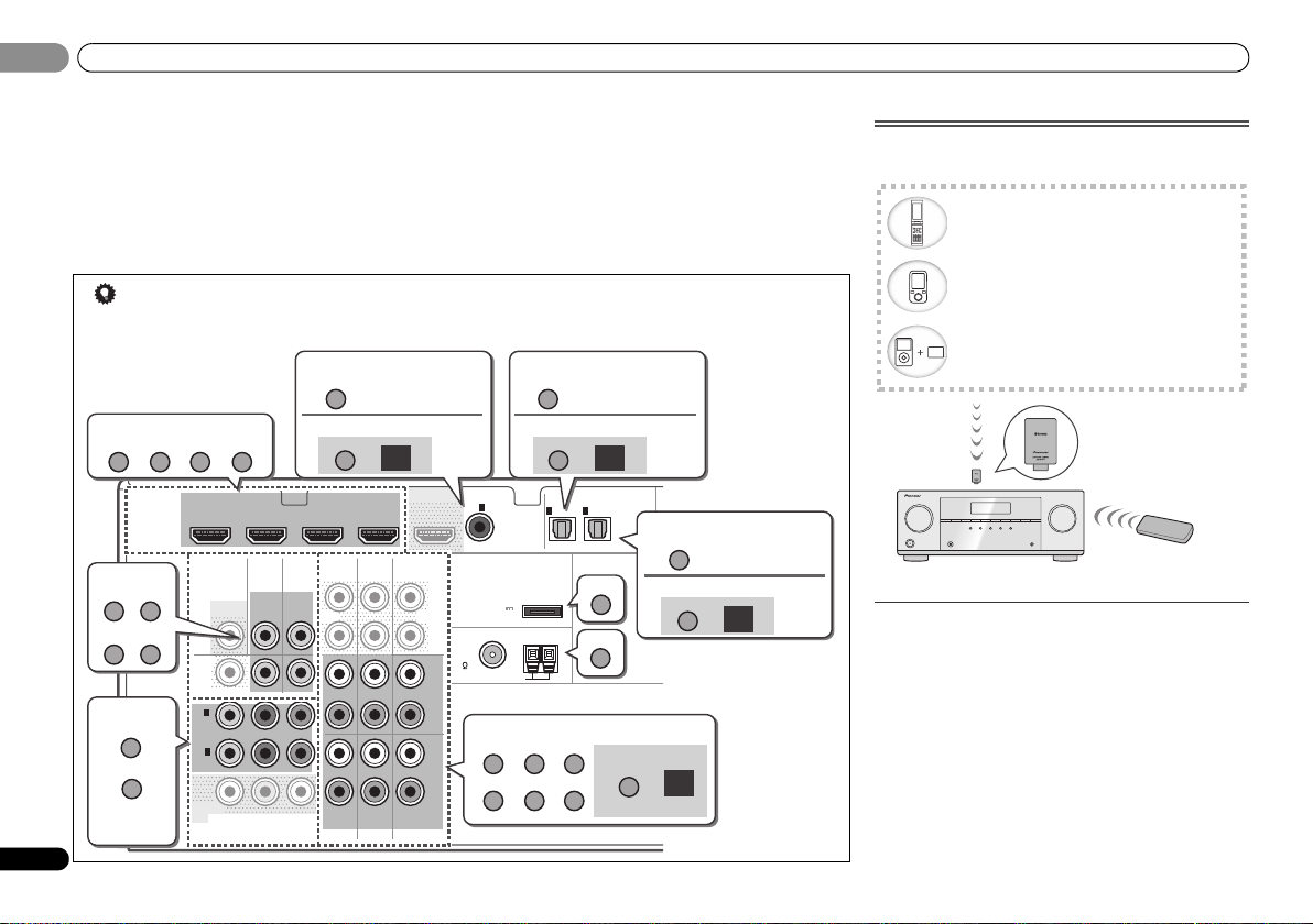
04
Bluetooth wireless technology enabled device:
cell phone
Bluetooth wireless technology enabled device:
Digital music player
Device not equipped with Bluetooth wireless
technology: Digital music player + Bluetooth
audio transmitter (sold commercially)
Music data
Remote control
operation
Bluetooth®
ADAPTER
This receiver
Tip
HDMI
VIDEO
COMPONENT VIDEO
DVR/
BDR
L
R
R
L
YP
BPR
COAXIAL
AUDIO
ANTENNA
OPTICAL
ASSIGNABLE
ASSIGNABLE
ASSIGNABLE
DVR/BDR
OUT
CD-R/TAPE
SURR BACK/
FRONT HEIGHT
L
R
PRE OUT
(
Single
)
IN
(CD)
1
IN IN
CD
TV/SATINBD
IN
OUT
IN DVD IN
IN
TV/SAT
BD
IN
DVD
(
DVD
)
IN
1
(
DVR/
BDR
)
IN
2
DVR/BDR IN DV D IN BD IN VIDEO IN
(
TV/SAT
)
IN
1
(
CD-R/TAPE
)
IN
2
FM
UNBAL
75
(
OUTPUT 5 V
0.1 A MAX
)
ADAPTER PORT
AM LOOP
OUT
MONITOR
OUT
MONITOR
OUT
DVD BD
CD
CD-R
ADAPTER
TUNER
TV
DVR/BDR
TV BD
DVR/BDR
DVD
DVR/BDR
DVD
CD-R CD
DVR/BDR
BD DVDTV
VIDEO
1.
1.
1.
O2
A
2.
SIGNAL SEL
SIGNAL SEL
O1
2.
SIGNAL SEL
C1
2.
SIGNAL SEL
Audio
Other than CD input
Audio
Audio
Audio
Video/Audio (HDMI)
Video
Video
Other than TV/SAT input
Other than CD-R input
(CD input)
(TV/SAT input)
(CD-R input)
Reassignable
(page 32)
04
Basic playback
• When digital input (optical or coaxial) is selected, this
receiver can only play back Dolby Digital, PCM (32 kHz to
96 kHz) and DTS (including DTS 96 kHz/24 bit) digital
signal formats. The compatible signals via the HDMI
terminals are: Dolby Digital, DTS, SACD (DSD 2 ch only),
PCM (32 kHz to 192 kHz sampling frequencies), Dolby
TrueHD, Dolby Digital Plus, DTS-EXPRESS, DTS-HD
Master Audio and DVD Audio (including 192 kHz). With
other digital signal formats, set to A (analog).
• In order to enjoy the picture and/or sound from devices connected to each terminal, select the input by doing the
following.
22
En
• You may get digital noise when a LD or CD player
compatible with DTS is playing an analog signal. To
prevent noise, make the proper digital connections
(page 13) and set the signal input to C1/O1/O2 (digital).
• Some DVD players don’t output DTS signals. For more
details, refer to the instruction manual supplied with your
DVD player.
Bluetooth® ADAPTER for Wireless Enjoyment
of Music
Wireless music play
When the Bluetooth ADAPTER (Pioneer Model No. AS-BT100
or AS-BT200) is connected to this unit, a product equipped
with Bluetooth wireless technology (portable cell phone,
digital music player, etc.) can be used to listen to music
wirelessly. Also, by using a commercially available
transmitter supporting Bluetooth wireless technology, you
can listen to music on a device not equipped with Bluetooth
wireless technology. The AS-BT100 and AS-BT200 model
supports SCMS-T contents protection, so music can also be
enjoyed on devices equipped with SCMS-T type Bluetooth
wireless technology.
• It must be necessary that the Bluetooth wireless
technology enabled device supports A2DP profiles.
Page 23
Basic playback
English
Français
Español
Important
• Pioneer does not guarantee proper connection and
operation of this unit with all Bluetooth wireless
technology enabled devices.
Remote control operation
The remote control supplied with this unit allows you to play
and stop media, and perform other operations.
• It must be necessary that the Bluetooth wireless
technology enabled device supports AVRCP profiles.
• Remote control operations cannot be guaranteed for all
Bluetooth wireless technology enabled devices.
Pairing the
wireless technology device
“Pairing” must be done before you start playback of Bluetooth
wireless technology content using Bluetooth ADAPTER.
Make sure to perform pairing first time you operate the
system or any time pairing data is cleared. “Pairing” is the
step necessary to register Bluetooth wireless technology
device to enable Bluetooth communications. For more
details, see also the operating instructions of your Bluetooth
wireless technology device.
• Pairing is required when you first use Bluetooth wireless
technology device and Bluetooth ADAPTER.
• To enable Bluetooth communication, pairing should be
done with both of your system and Bluetooth wireless
technology device.
•If the Bluetooth wireless technology device’s security
code is “0000”, there is no need to make the security code
setting on the receiver. Press ADAPTER to switch the
ADAPTER input, then conduct the pairing operation on
the Bluetooth wireless technology device. If pairing is
successful, there is no need to performing the pairing
operation below.
• When using the AS-BT200 only: If the Bluetooth wireless
technology device supports SSP (Secure Simple Pairing),
there is no need to make the security code setting. Press
ADAPTER to switch the ADAPTER input, then conduct
the pairing operation on the Bluetooth wireless
technology device. If pairing is successful, there is no
need to performing the pairing operation below.
Bluetooth
ADAPTER and
Bluetooth
1
Press TOP MENU.
2
Press ENTER to enter PAIRING.
3
Select the PIN code to be used from 0000/1234/8888
using
/
PAIRING blinks.
• You can use any of 0000/1234/8888 PIN codes. Bluetooth
4
that you want to make pairing, place it near the system and
set it into the pairing mode.
5
the
When Bluetooth wireless technology device is connected:
Bluetooth wireless technology device name appears in the
receiver display.
• The system can display alphanumeric characters only.
When Bluetooth wireless technology device is not connected:
NODEVICE appears in the receiver display. In this case,
perform the connection operation from the side of the
Bluetooth wireless technology device.
6
select
in the step 4.
• PIN code may in some case be referred to as PASSKEY.
Listening to Music Contents of
, then press ENTER.
wireless technology device using any other PIN code
cannot be used with this system.
Switch on the
Check to see that the
Bluetooth
Other characters may not be displayed correctly.
From the
Bluetooth
Bluetooth
wireless technology device
Bluetooth
wireless technology device.
Bluetooth
wireless technology device list,
ADAPTER and enter the PIN code selected
ADAPTER is detected by
Bluetooth
technology device with Your System
1
Press ADAPTER to switch the receiver to ADAPTER
input.
The ADAPTER input can also be selected by pressing
SOUND RETRIEVER AIR on the front panel. In this case, S.R
AIR, the optimum listening mode, is selected automatically.
2
Perform the connection operation from the side of the
Bluetooth
wireless technology device to the
ADAPTER.
• When the Bluetooth ADAPTER is not plugged into the
ADAPTER PORT terminal, NO ADAPTER will be
displayed if ADAPTER input is selected.
wireless
Bluetooth
3
Start playback of music contents stored in
wireless technology device.
This receiver’s remote control buttons can be used for basic
playback of files stored on the Bluetooth wireless technology
device.
• Bluetooth wireless technology device should be
compatible with AVRCP profile.
• Depending on Bluetooth wireless technology device you
use, operation may differ from what is shown in the
remote control buttons.
MUTE
TRE
BASS
The Bluetooth
trademarks owned by Bluetooth SIG, Inc. and any use of such
marks by Pioneer Corporation is under license. Other
trademarks and trade names are those of their respective
owners.
®
word mark and logos are registered
Bluetooth
04
04
23
En
Page 24
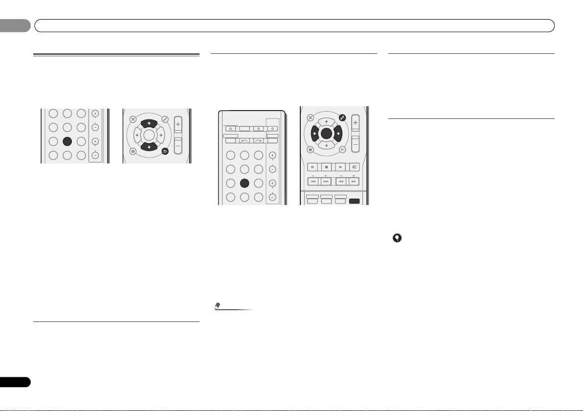
04
Note
Tip
CH
VOL
DVR/BDRCDCD-R
ADAPTER
TUNER
PORTABLE
VIDEO
SIGNAL SELS.RETRIEVER
ENTER
RETURN
AUDIO
PARAMETER
TUNER EDIT
TOOLS
MASTER
VOLUME
BAND
MENU
TOP
MENU
T
U
N
E
T
U
N
E
P
R
E
S
E
T
P
R
E
S
E
T
HOME
MENU
SETUP
INPUT SELECT
SOURCESLEEP
TV
CONTROL
INPUT
RECEIVER
CH
VOL
RECEIVER
BD DVD TV
DVR/BDRCDCD-R
ADAPTER
TUNER
PORTABLE
VIDEO
SIGNAL SELS.RETRIEVER
DTV/TV
1
ENTER
2
DISP
3
MUTE
RETURN
AUDIO
PARAMETER
TUNER EDIT
TOOLS
MASTER
VOLUME
BAND
MENU
TRE
BASS
TOP
MENU
T
U
N
E
T
U
N
E
P
R
E
S
E
T
P
R
E
S
E
T
HDD DVD VCR
HOME
MENU
SETUP
04
Basic playback
Listening to the radio
The following steps show you how to tune in to FM and AM
radio broadcasts using the automatic (search) and manual
(step) tuning functions. Once you are tuned to a station you
can memorize the frequency for recall later—see Saving
station presets below for more on how to do this.
1
Press TUNER to select the tuner.
2
Use BAND to change the band (FM or AM), if necessary.
Each press switches the band between FM (stereo or mono)
and AM.
3
Tune to a station.
There are three ways to do this:
Automatic tuning
To search for stations in the currently selected band,
press and hold TUNE / for about a second. The
receiver will start searching for the next station, stopping
when it has found one. Repeat to search for other
stations.
Manual tuning
To change the frequency one step at a time, press
TUNE /.
High speed tuning
Press and hold TUNE / for high speed tuning.
Release the button at the frequency you want.
Improving FM sound
24
En
If the TUNE or ST indicators don’t light when tuning to an FM
station because the signal is weak, set the receiver to the
mono reception mode.
Press BAND to select FM MONO.
This should improve the sound quality and allow you to enjoy
the broadcast.
Saving station presets
If you often listen to a particular radio station, it’s convenient
to have the receiver store the frequency for easy recall
whenever you want to listen to that station. This saves the
effort of manually tuning in each time. This unit can
memorize up to 30 stations.
1
Tune to a station you want to memorize.
See Listening to the radio on page 24 for more on this.
2
Press TUNER EDIT.
The display shows PRESET, then a blinking MEM and station
preset.
3
Press PRESET
want.
You can also use the number buttons.
4
Press ENTER.
The preset number stop blinking and the receiver stores the
station.
• If the receiver is left disconnected from the AC power
outlet for over a month, the station memories will be lost
and will have to be reprogrammed.
• Stations are stored in stereo. When the station is stored
in the FM MONO mode, it shows as ST when recalled.
/
to select the station preset you
Listening to station presets
You will need to have some presets stored to do this. See
Saving station presets above if you haven’t done this already.
Press PRESET
want.
• You can also use the number buttons on the remote
control to recall the station preset.
/
to select the station preset you
Naming preset stations
For easier identification, you can name all of your preset
stations.
1
Choose the station preset you want to name.
See Listening to station presets above for how to do this.
2
Press TUNER EDIT twice.
The cursor at the first character position is blinking on the
display.
3
Input the name you want.
Choose a name up to eight characters long.
•Use PRESET / to select character position.
•Use TUNE / to select characters.
• The name is stored when ENTER is pressed.
• To erase a station name, follow steps 1 and 2, and press
ENTER while the display is blank. Press TUNER EDIT
while the display is blank, to keep the previous name.
• Once you have named a station preset, Press DISP to
show the name. When you want to return to the frequency
display, press DISP several times to show the frequency.
Page 25
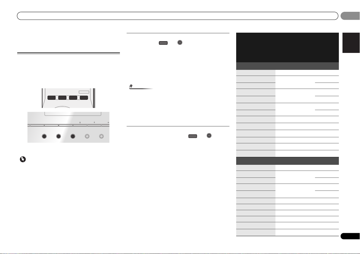
Listening to your system
English
Français
Español
Important
Note
ADV SURR
AUTO/
DIRECT
AUDIO
PARAMETER
TUNER EDIT
TOOLS
MASTER
VOLUME
BD MENU
ALC/
STANDARD
STEREO
ALC/
STANDARD
ALC/
STANDARD SURR
05
05
Chapter 5:
Listening to your system
Choosing the listening mode
This receiver offers a variety of listening modes to
accommodate playback of various audio formats. Choose
one according to your speaker environment or the source.
While listening to a source, press the listening mode
button repeatedly to select a listening mode you want.
DISPLAY BAND TUNER EDIT TUNE
SOUND
AUTO SURROUND
/
STREAM DIRECT
• The listening mode is shown on the display on the front
panel.
• The listening modes and many features described in this
section may not be available depending on the current
source, settings and status of the receiver.
ALC/
STANDARD SURR
ADVANCED
SURROUND
RETRIEVER AIR
SOUND
RETRIEVER
AUTO SURROUND
STREAM DIRECT
/
Auto playback
The simplest, most direct listening option is the AUTO
SURROUND feature. With this, the receiver automatically
detects what kind of source you’re playing and selects
multichannel or stereo playback as necessary.
•Press AUTO/DIRECT repeatedly until AUTO SURROUND
shows briefly in the display (it will then show the decoding
or playback format). Check the digital format indicators in
the display to see how the source is being processed.
• Stereo surround (matrix) formats are decoded
accordingly using NEO:6 CINEMA or DOLBY PLIIx
MOVIE (see Listening in surround sound below for more
on these decoding formats).
• When listening to the ADAPTER input, the S.R AIR
feature is selected automatically (see Using the Advanced
surround on page 26 for more on this).
AUTO/
DIRECT
Listening in surround sound
Using this receiver, you can listen to any source in surround
sound. However, the options available will depend on your
speaker setup and the type of source you’re listening to.
• If the source is Dolby Digital, DTS, or Dolby Surround
encoded, the proper decoding format will automatically
be selected and shows in the display.
When you select STEREO ALC (Auto Level Control stereo
mode), this unit equalizes playback sound levels if each
sound level varies with the music source recorded in a
portable audio player.
When you select STEREO, you will hear the source through
just the front left and right speakers (and possibly your
subwoofer depending on your speaker settings). Dolby
Digital and DTS multichannel sources are downmixed to
stereo.
The following modes provide basic surround sound for stereo
and multichannel sources.
Explanatory notes
No: No connected / Yes: Connected / Two: Two speakers are
connected / –: Whether connected or no
Type of surround
modes
Suitable sources
Surround back
speaker(s)
Two channel sources
STEREO ALC See above. – –
DOLBY PLIIx MOVIE Movie
Yes
a
DOLBY PLII MOVIE No –
b
DOLBY PLIIx MUSIC
DOLBY PLII MUSIC
Music
b
DOLBY PLIIx GAME Video games
a
Yes
No –
a
Yes
DOLBY PLII GAME No –
c
DOLBY PLIIz HEIGHT
NEO:6 CINEMA
NEO:6 MUSIC
Movie/Music No Yes
d
Movie – –
d
Music – –
DOLBY PRO LOGIC Old movies – –
e
Straight Decode
f
STEREO
No additional effects No –
See above. – –
Multichannel sources
STEREO ALC See above. – –
DOLBY PLIIx MOVIE Movie
Two
a
DOLBY PLII MOVIE No –
DOLBY PLIIx MUSIC
DOLBY PLII MUSIC
b
Music
b
a
Two
No –
DOLBY DIGITAL EX Movie/Music Yes No
DTS-ES Movie/Music Yes No
DTS NEO:6 Movie/Music Yes No
DOLBY PLIIz HEIGHT Movie/Music No Yes
e
Straight Decode
f
STEREO
No additional effects – –
See above. – –
Front height
speakers
No
No
No
No
No
25
En
Page 26
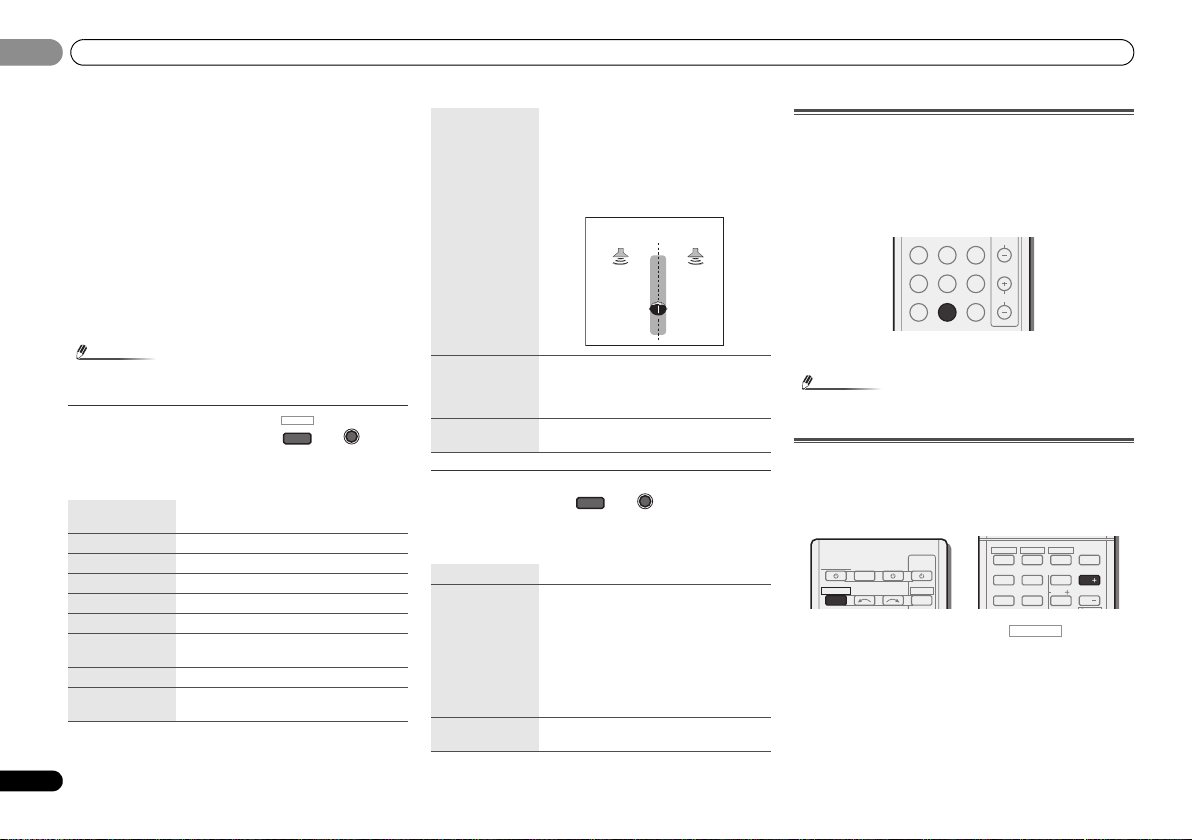
Listening to your system
Note
Note
Front left
speaker
Front right
speaker
AUTO/
DIRECT
AUTO SURROUND
/
STREAM DIRECT
RECEIVER
05
05
a. If surround back channel processing (page 27) is switched off,
or the surround back speakers are set to NO, DOLBY PLIIx
becomes DOLBY PLII (5.1 channel sound).
b. You can also adjust the C.WIDTH, DIMEN., and PNRM. effect
(see Setting the Audio options on page 28).
c. You can also adjust the H.GAIN effect (see Setting the Audio
options on page 28).
d. You can also adjust the C.IMG effect (see Setting the Audio
options on page 28).
e. Cannot be selected when the Pre Out is set to Surr. Back (see
The Pre Out Setting on page 33).
f. • You can choose the STEREO mode by using STEREO button
on the remote control.
• The audio is heard with your surround settings and you can
still use the Midnight, Loudness, Phase Control, Sound
Retriever and Tone functions.
• In modes that give 6.1 channel sound, the same signal is
heard from both surround back speakers.
BD MENU
Using the Advanced surround
The Advanced surround feature creates a variety of surround
effects. Try different modes with various soundtracks to see
which you like.
ACTION Designed for action movies with dynamic
soundtracks.
ADV SURR
DRAMA Designed for movies with lots of dialog.
ENT.SHOW Suitable for musical sources.
ADVANCED GAME Suitable for video games.
SPORTS Suitable for sports programs.
CLASSICAL Gives a large concert hall-type sound
ROCK/POP Creates a liv e concert sound for rock and/or
pop music.
UNPLUGGED Suitable for acoustic music sources.
EXT.STEREO Gives multichannel sound to a stereo
source, using all of your speakers
ADVANCED
SURROUND
F.S.S.ADVANCE
(Front Stage
Surround
ADVANCE)
S.R AIR
(Sound Retriever
AIR)
PHONES SURR When listening through headphones, you
Allows you to create natural surround
sound effects using just the front speakers
and the subwoofer.
Use to provide a rich surround sound effect
directed to the center of where the front left
and right speakers sound projection area
converges.
Suitable for listening to the sound from a
Bluetooth wireless technology device.
The S.R AIR listening mode can only
selected when the ADAPTER input.
can still get the effect of overall surround
Using Stream Direct
Use the Stream Direct modes when you want to hear the
truest possible reproduction of a source. All unnecessary
signal processing is bypassed.
AUTO SURROUND See Auto playback on page 25.
DIRECT Sources are heard according to the settings
PURE DIRECT Analog and PCM sources are heard without
made in the Manual SP Setup (speaker
setting, channel level, speaker distance), as
well as with dual mono settings. You will
hear sources according to the number of
channels in the signal.
Phase Control, Acoustic Calibration EQ,
Sound Delay, Auto Delay, LFE Attenuate
and Center image functions are available.
any digital processing.
Using the Sound Retriever
When audio data is removed during the compression
process, sound quality often suffers from an uneven sound
image. The Sound Retriever feature employs new DSP
technology that helps bring CD quality sound back to
compressed 2-channel audio by restoring sound pressure
and smoothing jagged artifacts left over after compression.
DVR/BDRCDCD-R
TUNER
ADAPTER
VIDEO
Press S.RETRIEVER to switch the S.RTV (Sound Retriever)
ON or OFF.
• The Sound Retriever is only applicable to 2-channel
sources.
PORTABLE
SIGNAL SELS.RETRIEVER
CH
VOL
Listening with Acoustic Calibration EQ
You can listen to sources using the Acoustic Calibration
Equalization set in Automatically setting up for surround
sound (MCACC) on page 19. Refer to these pages for more on
Acoustic Calibration Equalization.
HDD DVD VCR
RECEIVER
RECEIVER
While listening to a source, press , then press
EQ to switch the EQ (Acoustic Calibration EQ) ON or OFF.
The MCACC indicator on the front panel lights when Acoustic
Calibration EQ is active.
• You can’t use Acoustic Calibration EQ with Stream Direct
mode and it has no effect with headphones.
SOURCESLEEP
INPUT SELECT
TV
CONTROL
DTV/TV
INPUT
1
4
MIDNIGHT
7
SPEAKERS
SB CH
2
5
8
3
CH SELECT
6
LEV
9
DISP
EQ
CH
PHASE
CH
26
En
Page 27

Listening to your system
English
Français
Español
Note
Note
RECEIVER
INPUT SELECT
SOURCESLEEP
TV
CONTROL
INPUT
RECEIVER
RECEIVER
1
4
7
MIDNIGHT
2
5
8
SPEAKERS
LEV
SB CH
DISP
EQ
PHASE
3
6
9
CH
CH
CH SELECT
HDD DVD VCR
DTV/TV
RECEIVER
C
SW
L R
SL SR
SBL SBR SBL SBR
C
SW
L R
SL SR
UP MIX OFF UP MIX ON
05
05
Better sound using Phase Control
This receiver’s Phase Control feature uses phase correction
measures to make sure your sound source arrives at the
listening position in phase, preventing unwanted distortion
and/or coloring of the sound.
Phase Control technology provides coherent sound
reproduction through the use of phase matching for an
optimal sound image at your listening position. The default
setting is on and we recommend leaving Phase Control
switched on for all sound sources.
HDD DVD VCR
MIDNIGHT
1
4
7
RECEIVER
SOURCESLEEP
RECEIVER
INPUT SELECT
Press , then press PHASE to switch the P.CTL
(Phase Control) ON or OFF.
• Phase matching is a very important factor in achieving
proper sound reproduction. If two waveforms are ‘in
phase’, they crest and trough together, resulting in
increased amplitude, clarity and presence of the sound
signal. If a crest of a wave meets a trough, then the sound
will be ‘out of phase’ and an unreliable sound image will
be produced.
• If your subwoofer has a phase control switch, set it to the
plus (+) sign (or 0°). However, the effect you can actually
feel when Phase Control is set to ON on this receiver
depends on the type of your subwoofer. Set your
subwoofer to maximize the effect. It is also recommended
you try changing the orientation or the place of your
subwoofer.
• Set the built-in lowpass filter switch of your subwoofer to
OFF. If this cannot be done on your subwoofer, set the
cutoff frequency to a higher value.
• If the speaker distance is not properly set, you may not
have a maximized Phase Control effect.
• The Phase Control mode cannot be set to ON in the
following cases:
-
When the PURE DIRECT mode is switched on.
-
When the headphones are connected.
TV
CONTROL
DTV/TV
INPUT
SPEAKERS
SB CH
2
5
8
3
CH SELECT
6
LEV
9
DISP
EQ
CH
PHASE
CH
Using surround back channel processing
You can have the receiver automatically use 6.1 or 7.1
decoding for 6.1 encoded sources (for example, Dolby Digital
EX or DTS-ES), or you can choose to always use 6.1 or 7.1
decoding (for example, with 5.1 encoded material). With 5.1
encoded sources, a surround back channel will be
generated, but the material may sound better in the 5.1
format for which it was originally encoded (in which case, you
can simply switch surround back channel processing off).
• With a 7.1-channel surround system, audio signals that
have undergone matrix decoding processing through
surround back channel processing to which the Up Mix
function is added are output from the surround back
speakers.
Press , then press SB CH repeatedly to cycle
the surround back channel options.
Each press cycles through the options as follows:
• SB ON – Matrix decoding processing for generating the
surround back component from the surround component
is turned on.
• SB AUTO – Matrix decoding processing for generating
the surround back component from the surround
component is switched automatically. Matrix decoding
processing is only performed when surround back
channel signals are detected in the input signals.
• SB OFF – Matrix decoding processing for generating the
surround back component from the surround component
is turned off.
Setting the Up Mix function
In a 7.1-channel surround system with surround speakers
placed directly at the sides of the listening position, the
surround sound of 5.1-channel sources is heard from the
side. The Up Mix function mixes the sound of the surround
speakers with the surround back speakers so that the
surround sound is heard from diagonally to the rear as it
should be.
• Using the Up Mix function is effective when the speakers
in the 7.1-channel surround system are set up as
recommended in the example on page 10.
• Depending on the positions of the speakers and the
sound source, in some cases it may not be possible to
achieve good results. In this case, set the setting to OFF.
1
Switch the receiver into standby.
2
While holding down PRESET on the front panel, and
hold the
STANDBY/ON
UP MIX: OFF appears and the Up Mix function turns off. If
you want to turn this function on, perform steps 1 and 2
again.
• When set to ON, the (Up Mix) indicator on the front
panel lights.
•Set to ON regardless of this setting when playing DTS-HD
signals.
• May automatically be set to OFF even when set to ON,
depending on the input signal and listening mode.
for about two seconds.
27
En
Page 28
Listening to your system
Important
INPUT SELECT
SOURCESLEEP
TV
CONTROL
INPUT
RECEIVER
RECEIVER
BD DVD TV
DTV/TV
ENTER
RETURN
AUDIO
PARAMETER
TUNER EDIT
TOOLS
MASTER
VOLUME
BAND
MENU
TOP
MENU
T
U
N
E
T
U
N
E
P
R
E
S
E
T
P
R
E
S
E
T
HOME
MENU
SETUP
RECEIVER
05
05
28
En
Setting the Audio options
There are a number of additional sound settings you can
make using the AUDIO PARAMETER menu. The defaults, if
not stated, are listed in bold.
• Note that if a setting doesn’t appear in the AUDIO
PARAMETER menu, it is unavailable due to the current
source, settings and status of the receiver.
1
Press , then press AUDIO PARAMETER button.
2
Use
/
Depending on the current status/mode of the receiver,
certain options may not be able to be selected. Check the
table below for notes on this.
3
See the table below for the options available for each setting.
4
Setting/What it does Option(s)
EQ (Acoustic Calibration EQ)
Switches on/off the effect of Acoustic
Calibration EQ.
S.DELAY (Sound Delay)
Some monitors have a slight delay when
showing video, so the soundtrack will be
slightly out of sync with the picture. By adding
a bit of delay, you can adjust the sound to
match the presentation of the video.
MIDNIGHT/LOUDNESS
The MIDNIGHT allows you to hear effective
surround sound of movies at low volumes.
The LOUDNESS is used to get good bass and
treble from music sources at low volumes.
to select the setting you want to adjust.
Use
/
to set it as necessary.
Press RETURN to confirm and exit the menu.
1 second = 30
frames (NTSC)
a
ON
OFF
0.0 to 9.0
(frames)
Default: 0.0
M/L OFF
MIDNIGHT
LOUDNESS
Setting/What it does Option(s)
S.RTV (Sound Retriever)
When audio data is removed during the
compression process, sound quality often
suffers from an uneven sound image. The
Sound Retriever feature employs new DSP
technology that helps bring CD quality sound
back to compressed 2-channel audio by
restoring sound pressure and smoothing
jagged artifacts left over after compression.
DUAL MONO
Specifies how dual mono encoded Dolby
Digital soundtracks should be played.
F.PCM (Fixed PCM)
This is useful if you find there is a slight delay
before OFF recognizes the PCM signal on a
CD, for instance.
When ON is selected, noise may be output
during playback of non-PCM sources. Please
select another input signal if this is a problem.
DRC (Dynamic Range Control)
Adjusts the level of dynamic range for movie
soundtracks optimized for Dolby Digital, DTS,
Dolby Digital Plus, Dolby TrueHD, DTS-HD
and DTS-HD Master Audio (you may need to
use this feature when listening to surround
sound at low volumes).
b
OFF
ON
d
CH1 – Channel 1
is heard only
CH2 – Channel 2
is heard only
CH1 CH2 – Both
channels heard
from front
speakers
OFF
ON
AUTO
MAX
MID
OFF
Setting/What it does Option(s)
c
LFE ATT (LFE Attenuate)
Some Dolby Digital and DTS audio sources
include ultra-low bass tones. Set the LFE
attenuator as necessary to prevent the ultralow bass tones from distorting the sound from
the speakers.
The LFE is not limited when set to 0 dB, which
is the recommended value. When set to –15
dB, the LFE is limited by the respective
degree. When OFF is selected, no sound is
output from the LFE channel.
SACD G. (SACD Gain)
Brings out detail in SACDs by maximizing the
dynamic range (during digital processing).
HDMI (HDMI Audio)
Specifies the routi ng of the HDMI audio signal
out of this receiver (AMP) or through to a TV
(THRU). When THRU is selected, no sound is
output from this receiver.
A.DLY (Auto Delay)
This feature automatically corrects the audioto-video delay between components
connected with an HDMI cable. The audio
delay time is set depending on the operational
status of the display connected with an HDMI
e
cable. The video delay time is automatically
adjusted according to the audio delay time.
C.WIDTH (Center Width)
(Applicable only when using a center speaker)
Spreads the center channel between the front
right and left speakers, making it sound wider
(higher settings) or narrower (lower settings).
DIMEN (Dimension)
Adjusts the surround sound balance from
front to back, making the sound more distant
(minus settings), or more forward (positive
settings).
f
g
h
h
0 (0 dB)
5 (–5 dB)
10 (–10 dB)
15 (–15 dB)
20 (–20 dB)
** (OFF)
0 (0 dB)
+6 (+6 dB)
AMP
THRU
OFF
ON
0 to 7
Default: 3
–3 to +3
Default: 0
Page 29

Listening to your system
English
Français
Español
Note
INPUT SELECT
SOURCESLEEP
TV
CONTROL
INPUT
RECEIVER
CH
VOL
RECEIVER
BD DVD TV
DVR/BDRCDCD-R
ADAPTER
TUNER
PORTABLE
VIDEO
SIGNAL SELS.RETRIEVER
DTV/TV
05
05
Setting/What it does Option(s)
h
i
PNRM. (Panorama)
Extends the front stereo image to include
surround speakers for a ‘wraparound’ effect.
C.IMG (Center Image)
(Applicable only when using a center speaker)
Adjust the center image to create a wider
stereo effect with vocals. Adjust the effect
from 0 (all center channel sent to front right
and left speakers) to 10 (center channel sent
to the center speaker only).
H.GAIN (Height Gain)
Adjusts the output from the front height
speaker when listening in DOLBY PLIIz
HEIGHT mode. If set to H, the sound from the
top will be more emphasized.
a. You can change the MIDNIGHT/LOUDNESS options at any
time by using MIDNIGHT button.
b. You can change the Sound Retriever feature at any time by
using S.RETRIEVER button.
c. The default setting when the ADAPTER input is selected is
ON.
d. This setting works only with dual mono encoded Dolby Digital
and DTS soundtracks.
e. The initial set AUTO is only available for Dolby TrueHD signals.
Select MAX or MID for signals other than Dolby TrueHD.
f. You shouldn’t have any problems using this with most SACD
discs, but if the sound distorts, it is best to switch the gain
setting back to 0 dB.
g. This feature is only available when the connected display
supports the automatic audio/video synchronizing capability
(‘lip-sync’) for HDMI. If you find the automatically set delay
time unsuitable, set A.DLY to OFF and adjust the delay time
manually. For more details about the lip-sync feature of your
display, contact the manufacturer directly.
h. Only available with 2-channel sources in DOLBY PLII MUSIC
mode.
i. Only when listening to 2-channel sources in NEO:6 CINEMA
and NEO:6 MUSIC mode.
OFF
ON
0 to 10
Default: 3
(NEO:6 MUSIC),
10 (NEO:6
CINEMA)
L (Low)
M (Mid)
H (High)
Making an audio or a video recording
You can make an audio or a video recording from the built-in
tuner, or from an audio or video source connected to the
receiver (such as a CD player or TV).
Only video signals that were input to this receiver through a
composite video cable or analog audio inputs can be
recorded. Signals that were input through an HDMI cable,
component video cable or digital audio cable (see
Connecting other audio components on page 17 for more on
connections).
1
Press input function buttons to select the input function
you want to record.
The input of the receiver will switch over, and you will be able
to operate other components using the remote control.
• The input source can also be selected by using INPUT
SELECT buttons on the remote control, or by
using the front panel INPUT SELECTOR dial.
2
Select the audio input signal (if necessary).
Press SIGNAL SEL and select the analog inputs (A) for the
source component of which you want to record (see page 21
for more on this).
3
Prepare the source you want to record.
Tune to the radio station, load the CD, video, DVD etc.
4
Prepare the recorder.
Insert a blank tape, MD, video etc. into the recording device
and set the recording levels.
Refer to the instructions that came with the recorder if you
are unsure how to do this. Most video recorders set the audio
recording level automatically—check the component’s
instruction manual if you’re unsure.
5
Start recording, then start playback of the source
component.
• The receiver’s volume, balance, tone (bass, treble,
loudness), and surround effects have no effect on the
recorded signal.
• Some video sources are copy-protected. These cannot be
recorded.
29
En
Page 30
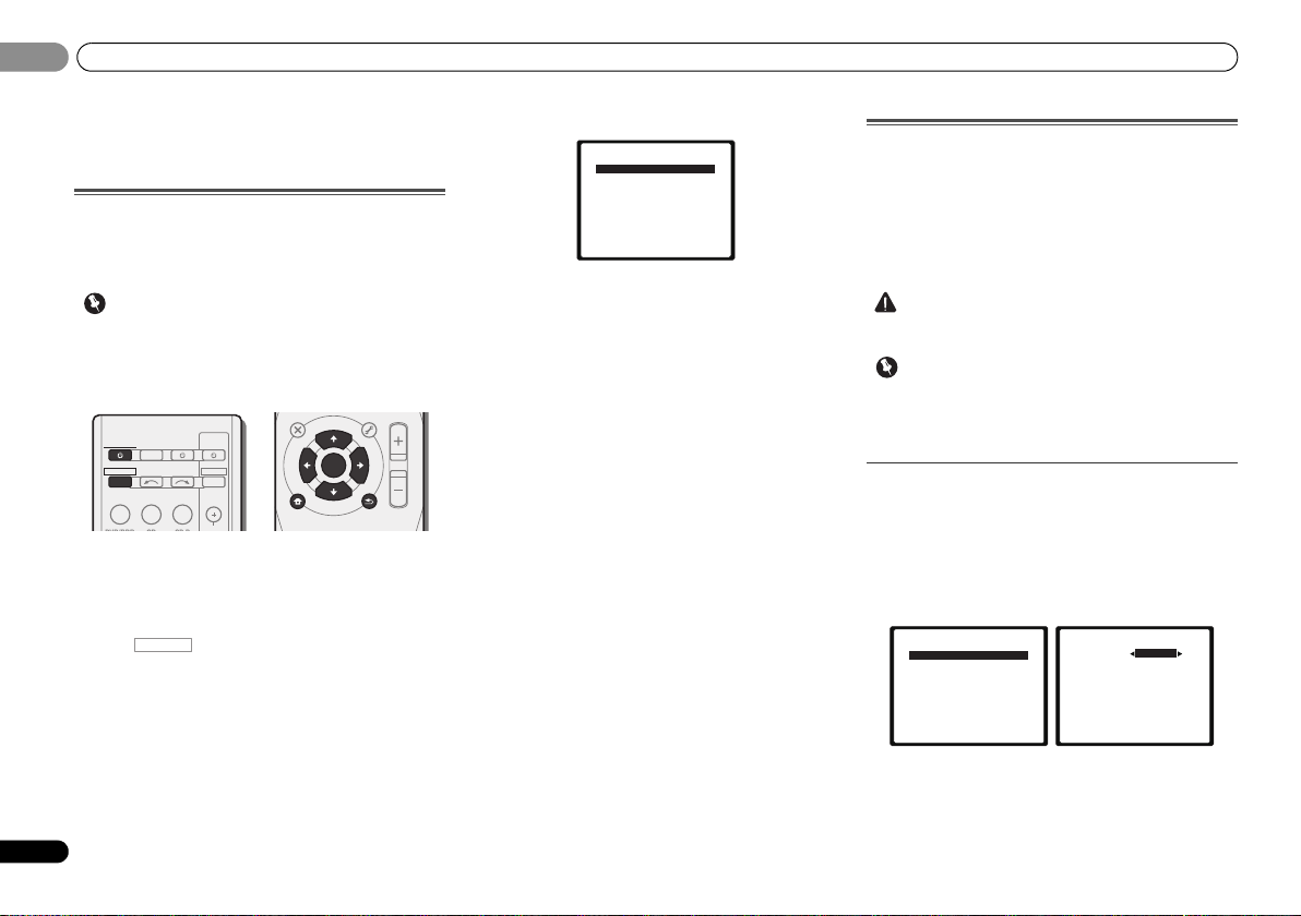
06
Important
CAUTION
Important
INPUT SELECT
SOURCESLEEP
TV
CONTROL
INPUT
RECEIVER
RECEIVER
BD DVD TV
DTV/TV
ENTER
MUTE
RETURN
PARAMETER
TOOLS
VOLUME
BAND
MENU
TOP
MENU
T
U
N
E
T
U
N
E
P
R
E
S
E
T
P
R
E
S
E
T
HOME
MENU
SETUP
System Setup
1.Auto MCACC
2.Manual SP Setup
3.Input Assign
4.Pre Out Setting
5.HDMI Setup
6.Auto Power Down
7.FL Demo Mode
Return
2.Manual SP Setup
Return
a.Speaker Setting
b.Crossover Network
c.Channel Level
d.Speaker Distance
2a.Speaker Setting
Front
Center
Surr
Surr. Back
Subwoofer:
Return
[ SMALL ]
[ SMALL ]
[ NO ]
YES
SMALL
06
Chapter 6:
The System Setup menu
Using the System Setup menu
The following section shows you how to make detailed
settings to specify how you’re using the receiver, and also
explains how to fine-tune individual speaker system settings
to your liking.
1
Press RECEIVER to switch on.
2
receiver to the TV through the corresponding composite or
component cable.
3
The System Setup menu appears on your TV. Use ///
and ENTER on the remote control to navigate through the
screens and select menu items. Press RETURN to confirm
and exit the current menu.
30
En
The System Setup menu
• The OSD will not appear if you have connected using the
HDMI output to your TV. Use component or composite
connections for system setup.
• If headphones are connected to the receiver, disconnect
them.
Switch on the receiver and your TV.
Switch the TV input to the input that connects this
RECEIVER
Press , then press SETUP.
• Press SETUP at any time to exit the System Setup menu.
4
Select the setting you want to adjust.
• Auto MCACC – This is a quick and effective automatic
surround setup (see Automatically setting up for surround
sound (MCACC) on page 19).
• Manual SP Setup
-
Speaker Setting – Specify the size and number of
speakers you’ve connected (see below).
-
Crossover Network – Specify which frequencies will be
sent to the subwoofer (page 31).
-
Channel Level – Adjust the overall balance of your
speaker system (page 31).
-
Speaker Distance – Specify the distance of your
speakers from the listening position (page 32).
• Input Assign – Specify what you’ve connected to the
component video inputs (see The Input Assign menu on
page 32).
• Pre Out Setting – Specify how to use the PRE OUT SURR
BACK/FRONT HEIGHT outputs (see The Pre Out Setting
on page 33).
• HDMI Setup – Sets synchronized operations when
connected to a device/TV that supports the Control with
HDMI function (see HDMI Setup on page 34).
• Auto Power Down – Sets to automatically turn off the
power when the receiver has not operated for several
hours (see The Auto Power Down menu on page 33).
• FL Demo Mode – Sets the demo display on the front
panel display (see The FL Demo Mode menu on page 33).
Manual speaker setup
This receiver allows you to make detailed settings to optimize
the surround sound performance. You only need to make
these settings once (unless you change the placement of
your current speaker system or add new speakers).
These settings are designed to fine-tune your system, but if
you’re satisfied with the settings made in Automatically
setting up for surround sound (MCACC) on page 19, it isn’t
necessary to make all of these settings.
• The test tones used in the System Setup are output at
high volume.
• Depending on the Pre Out Setting, there will be
differences in the speaker items that can be adjusted. The
OSD display for these operating instructions is an
example of when the Pre Out Setting is set to Surr. Back.
Speaker Setting
Use this setting to specify your speaker configuration (size,
number of speakers). It is a good idea to make sure that the
settings made in Automatically setting up for surround sound
(MCACC) on page 19 are correct.
1
Select ‘Manual SP Setup’ from the System Setup menu.
2
Select ‘Speaker Setting’ from the Manual SP Setup
menu.
3
Choose the set of speakers that you want to set then
select a speaker size.
Use / to select the size (and number) of each of the
following speakers:
Page 31

The System Setup menu
English
Français
Español
Note
2.Manual SP Setup
Return
a.Speaker Setting
b.Crossover Network
c.Channel Level
d.Speaker Distance
2b.Crossover Network
Return
Frequency 100Hz
2.Manual SP Setup
Return
a.Speaker Setting
b.Crossover Network
c.Channel Level
d.Speaker Distance
2c.Channel Level
Test Tone Manual
ENTER:NextReturn
2c.Channel Level
Test Tone [ Manual ]
Please Wait . . .20
Caution
Loud test tones
will be output.
Return
06
06
• Front – Select LARGE if your front speakers reproduce
bass frequencies effectively, or if you didn’t connect a
subwoofer. Select SMALL to send the bass frequencies to
the subwoofer.
• Center – Select LARGE if your center speaker reproduces
bass frequencies effectively, or select SMALL to send
bass frequencies to the other speakers or subwoofer. If
you didn’t connect a center speaker, choose NO (the
center channel is sent to the other speakers).
• Front Height – Select LARGE if your front height
speakers reproduce bass frequencies effectively. Select
SMALL to send bass frequencies to the other speakers or
subwoofer. If you didn’t connect front height speakers
choose NO.
-
You can only adjust the Front Height setting when Pre
Out Setting is set to Height.
• Surr – Select LARGE if your surround speakers reproduce
bass frequencies effectively. Select SMALL to send bass
frequencies to the other speakers or subwoofer. If you
didn’t connect surround speakers choose NO (the sound
of the surround channels is sent to the other speakers).
• Surr. Back – Select the number of surround back
speakers you have (one, two or none). Select LARGE if
your surround back speakers reproduce bass frequencies
effectively. Select SMALL to send bass frequencies to the
other speakers or subwoofer. If you didn’t connect
surround back speakers choose NO.
-
You can only adjust the Surr. Back setting when Pre
Out Setting is set to Surr. Back.
-
If you select one surround back speaker only, make sure
that additional amplifier is hooked up to the PRE OUT L
(Single) terminal.
• Subwoofer – LFE signals and bass frequencies of
channels set to SMALL are output from the subwoofer
when YES is selected (see notes below). Choose the PLUS
setting if you want the subwoofer to output bass sound
continuously or you want deeper bass (the bass
frequencies that would normally come out the front and
center speakers are also routed to the subwoofer). If you
did not connect a subwoofer choose NO (the bass
frequencies are output from other speakers).
4
When you’re finished, press RETURN.
You return to the Manual SP Setup menu.
• If you select SMALL for the front speakers, the subwoofer
will automatically be fixed to YES. Also, the center,
surround, surround back and front height speakers can’t
be set to LARGE if the front speakers are set to SMALL. In
this case, all bass frequencies are sent to the subwoofer.
• If the surround speakers are set to NO, the surround back
speakers will automatically be set to NO.
• If you have a subwoofer and like lots of bass, it may seem
logical to select LARGE for your front speakers and PLUS
for the subwoofer. This may not, however, yield the best
bass results. Depending on the speaker placement of
your room you may actually experience a decrease in the
amount of bass due to low frequency cancellations. In
this case, try changing the position or direction of
speakers. If you can’t get good results, listen to the bass
response with it set to PLUS and YES or the front speakers
set to LARGE and SMALL alternatively and let your ears
judge which sounds best. If you’re having problems, the
easiest option is to route all the bass sounds to the
subwoofer by selecting SMALL for the front speakers.
Crossover Network
• Default setting: 100Hz
This setting decides the cutoff between bass sounds playing
back from the speakers selected as LARGE, or the subwoofer,
and bass sounds playing back from those selected as
SMALL. It also decides where the cutoff will be for bass
sounds in the LFE channel.
• For more on selecting the speaker sizes, see Speaker
Setting on page 30.
1
Select ‘Manual SP Setup’ from the System Setup menu.
2
Select ‘Crossover Network’ from the Manual SP Setup
menu.
3
Choose the frequency cutoff point.
Frequencies below the cutoff point will be sent to the
subwoofer (or LARGE speakers).
4
When you’re finished, press RETURN.
You return to the Manual SP Setup menu.
Channel Level
Using the channel level settings, you can adjust the overall
balance of your speaker system, an important factor when
setting up a home theater system.
1
Select ‘Manual SP Setup’ from the System Setup menu.
2
Select ‘Channel Level’ from the Manual SP Setup menu.
3
Select a setup option.
• Manual – Move the test tone manually from speaker to
speaker and adjust individual channel levels.
• Auto – Adjust channel levels as the test tone moves from
speaker to speaker automatically.
4
Confirm your selected setup option.
The test tones will start after you press ENTER. After the
volume increases to the reference level, test tones will be
output.
31
En
Page 32

The System Setup menu
Note
Tip
Important
2c.Channel Level
Front L
Center
Front R
Surround R
Surr. Back R
Surr. Back L
Surround L
Subwoofer
Return
[ 0dB]
[ 0dB]
[ 0dB]
[ ––– ]
[ ––– ]
[ 0dB]
[ 0dB]
0dB
RECEIVER
2.Manual SP Setup
Return
a.Speaker Setting
b.Crossover Network
c.Channel Level
d.Speaker Distance
System Setup
1 . Auto MCACC
2 . Manual SP Setup
3 . Input Assign
4 . Pre Out Setting
5 . HDMI Setup
6 . Auto Power Down
7 . FL Demo Mode
Return
3.Input Assign
Return
a.Component Input
3a.Component Input
Return
Component–1
DVD
Component–2 [ DVR ]
06
06
5
Adjust the level of each channel using
If you selected Manual, use / to switch speakers. The
Auto setup will output test tones in the order shown on-
screen:
Adjust the level of each speaker as the test tone is emitted.
• If you are using a Sound Pressure Level (SPL) meter, take
the readings from your main listening position and adjust
the level of each speaker to 75 dB SPL (C-weighting/slow
reading).
• The subwoofer test tone is output at low volumes. You
may need to adjust the level after testing with an actual
soundtrack.
6
When you’re finished, press RETURN.
You return to the Manual SP Setup menu.
• You can change the channel levels at any time by press
remote control. You can also press CH SELECT and use
/ to select the channel, and then use / to adjust
the channel levels.
32
En
, then press CH SELECT and LEV +/– on the
/
.
Speaker Distance
For good sound depth and separation from your system, you
need to specify the distance of your speakers from the
listening position. The receiver can then add the proper delay
needed for effective surround sound.
1
Select ‘Manual SP Setup’ from the System Setup menu.
2
Select ‘Speaker Distance’ from the Manual SP Setup
menu.
2d.Speaker Distance
Front L
Center
Front R
Surround R
Surr. Back R
Surr. Back L
Surround L
Subwoofer
3
Adjust the distance of each speaker using
You can adjust the distance of each speaker in 0.1 feet
increments.
4
When you’re finished, press RETURN.
You return to the Manual SP Setup menu.
10.0 ft
[ 10.0 ft ]
[ 10.0 tt ]
[ 10.0 ft ]
[ –––– ]
[ –––– ]
[ 10.0 ft ]
[ 10.0 ft ]
Return
/
.
The Input Assign menu
You only need to make settings in the Input Assign menu if
you didn’t hook up your equipment according to the default
settings for the component video inputs.
• Default settings:
-
Component-1: DVD
-
Component-2: DVR (DVR/BDR)
If you didn’t make component video connections according
to the defaults above, you must assign the numbered input to
the component you’ve connected (or else you may see the
video signal of a different component). For more on this, see
Using the component video jacks on page 16.
1
Select ‘Input Assign’ from the System Setup menu.
2
Select ‘Component Input’ from the Input Assign menu.
3
Select the number of the component video input to
which you’ve connected your video component.
The numbers correspond with the numbers beside the inputs
on the rear of the receiver.
4
Select the component that corresponds with the one
you connected to that input.
Select between BD, DVD, TV (TV/SAT), DVR (DVR/BDR) or
OFF.
•Use / and ENTER to do this.
• If you connect any source component to the receiver
using a component video input, you should also have your
TV connected to this receiver’s COMPONENT VIDEO
MONITOR OUT output (down converting component
video is not possible after assigning an input).
• If you a ssign a component input to a certain function, any
component inputs previously assigned to that function
will automatically be switched off.
• Make sure you have connected the audio from the
component to the corresponding inputs on the rear of the
receiver.
5
When you’re finished, press RETURN.
You return to the Input Assign menu.
• For the assignment of the digital signal inputs, see
Selecting the audio input signal on page 21.
Page 33

The System Setup menu
English
Français
Español
System Setup
1 . Auto MCACC
2 . Manual SP Setup
3 . Input Assign
4 . Pre Out Setting
5 . HDMI Setup
6 . Auto Power Down
7 . FL Demo Mode
Return
4.Pre Out Setting
Return
Pre Out Surr. Back
System Setup
1 . Auto MCACC
2 . Manual SP Setup
3 . Input Assign
4 . Pre Out Setting
5 . HDMI Setup
6 . Auto Power Down
7 . FL Demo Mode
Return
6.Auto Power Down
Return
OFF
System Setup
1 . Auto MCACC
2 . Manual SP Setup
3 . Input Assign
4 . Pre Out Setting
5 . HDMI Setup
6 . Auto Power Down
7 . FL Demo Mode
Return
7.FL Demo Mode
Return
FL Demo ON
The Pre Out Setting
Specify either using the surround back speaker or the front
height speaker connection with the PRE OUT SURR BACK/
FRONT HEIGHT outputs. An additional amplifier is required
for the speaker connection.
• Default setting: Surr. Back
1
Select ‘Pre Out Setting’ from the System Setup menu.
2
Select which speaker to connect to the PRE OUT SURR
BACK/FRONT HEIGHT outputs using
• Surr. Back – Connect the surround back speaker.
/
• Height – Connect the front height speaker.
3
When you’re finished, press RETURN.
You return to the System Setup menu.
The Auto Power Down menu
Set to automatically turn off the receiver after a specified tim e
has passed (when the power has been on with no operation
for several hours.
• Default setting: OFF
1
Select ‘Auto Power Down’ from the System Setup
menu.
06
06
2
Specify the amount of time to allow before the power
is turned off (when there has been no operation).
• You can select 2, 4 or 6 hours, or OFF (if no automatic
shutoff is desired).
3
When you’re finished, press RETURN.
You return to the System Setup menu.
The FL Demo Mode menu
Set whether or not various demos are to be shown on the
front panel display.
1
Select ‘FL Demo Mode’ from the System Setup menu.
.
2
Choose ON or OFF for the demo display.
3
When you’re finished, press RETURN.
You return to the System Setup menu.
33
En
Page 34

Control with HDMI function
Important
Important
RECEIVER
System Setup
1 . Auto MCACC
2 . Manual SP Setup
3 . Input Assign
4 . Pre Out Setting
5 . HDMI Setup
6 . Auto Power Down
7 . FL Demo Mode
Return
5.HDMI Setup
Return
Control ON
ARC [ OFF ]
07
07
Chapter 7:
Control with HDMI
function
Synchronized operations below with a Control with HDMIcompatible Pioneer TV or Blu-ray Disc player or with a
component of another make that supports the Control with
HDMI functions are possible when the component is
connected to the receiver using an HDMI cable.
• Synchronized amp mode
• Power synchronization with TV
• Automatic switching of inputs
• With Pioneer devices, the Control with HDMI functions
• You cannot use this function with components that do not
• We only guarantee this receiver will work with Pioneer
• Use a High Speed HDMI
• For details about concrete operations, settings, etc., refer
34
En
The receiver’s volume can be set and the sound can be
muted using the TV’s remote control.
The receiver’s input switches over automatically when the
TV’s input is changed or a Control with HDMI-compatible
component is played.
are referred to as “KURO LINK”.
support Control with HDMI.
made Control with HDMI-compatible components and
components of other makes that support the Control
with HDMI function. However, we do not guarantee that
all synchronized operations will work with components of
other makes that support the Control with HDMI
function.
Control with HDMI function. The Control with HDMI
function may not work properly if a different type of HDMI
cable is used.
®
cable when you want to use the
to also the operating instructions for each component.
Making Control with HDMI connections
You can use synchronized operation for a connected TV and
up to four other components.
• Be sure to connect the TV’s audio cable to t he audio input
of this unit. When the TV and receiver are connected by
HDMI connections, if the TV supports the HDMI Audio
Return Channel function, the sound of the TV is input to
the receiver via the HDMI terminal, so there is no need to
connect an audio cable. In this case, set ARC at HDMI
Setup to ON (see HDMI Setup below).
For details, see Connecting using HDMI on page 14.
• When connecting this system or changing connections,
be sure to switch the power off and disconnect the power
cord from the wall socket.
After completing all connections, connect the power
cords to the wall socket.
• After this receiver is connected to an AC outlet, a 2
second to 10 second HDMI initialization process begins.
You cannot carry out any operations during initialization.
The HDMI indicator on the display unit blinks during
initialization, and you can turn this receiver on once it has
stopped blinking.
• To get the most out of this function, we recommend that
you connect your HDMI component not to a TV but rather
directly to the HDMI terminal on this receiver.
• While the receiver is equipped with four HDMI inputs, the
Control with HDMI function can only be used with up to
three DVD or Blu-ray Disc players or up to three DVD or
Blu-ray Disc recorders.
HDMI Setup
You must adjust the settings of this receiver as well as the
connected Control with HDMI-compatible components in
order to make use of the Control with HDMI function. For
more information see the operating instructions for each
component.
1
Switch on the receiver and your TV.
Press RECEIVER to switch on.
2
Switch the TV input to the input that connects this
receiver to the TV through the corresponding composite or
component cable.
3
Press , then press SETUP.
The System Setup menu appears on your TV. Use ///
and ENTER on the remote control to navigate through the
screens and select menu items. Press RETURN to confirm
and exit the current menu.
•Press SETUP at any time to exit the System Setup menu.
4
Select ‘HDMI Setup’ from the System Setup menu.
5
Select the ‘Control’ setting you want.
Choose whether to set this unit’s Control with HDMI
function ON or OFF. You will need to set it to ON to use the
Control with HDMI function.
When using a component that does not support the Control
with HDMI function, set this to OFF.
• ON – Enables the Control with HDMI function. When this
unit’s power is turned off and you have a supported
source begin playback while using the Control with
HDMI function, the audio and video outputs from the
HDMI connection are output from the TV.
• OFF – The Control with HDMI is disabled. Synchronized
operations cannot be used. When this unit’s power is
turned off, audio and video of sources connected via
HDMI are not output.
Page 35

Control with HDMI function
English
Français
Español
07
07
6
Select the ‘ARC’ setting you want.
When a TV supporting the HDMI Audio Return Channel
function is connected to the receiver, the sound of the TV can
be input via the HDMI terminal.
• ON – The TV’s sound is input via the HDMI terminal. This
can only be selected when Control is set to ON.
• OFF – The TV’s sound is input from the audio input
terminals other than HDMI inputs.
7
When you’re finished, press RETURN.
You return to the System Setup menu.
Before using synchronization
Once you have finished all connections and settings, you
must:
1
Put all components into standby mode.
2
Turn the power on for all components, with the power
for the TV being turned on last.
3
Choose the HDMI input to which the TV is connected to
this receiver, and see if video output from connected
components displays properly on the screen or not.
4
Check whether the components connected to all HDMI
inputs are properly displayed.
About synchronized operations
The Control with HDMI-compatible component connected to
the receiver operates in sync as described below.
• Synchronized amp mode
-
From the menu screen of the Control with HDMIcompatible TV, set audio to be played through this
receiver, and the receiver will switch to the synchronized
amp mode.
-
When in the synchronized amp mode, the synchronized
amp mode is canceled when the receiver’s power is
turned off. To turn the synchronized amp mode back on,
set audio to be played through the receiver from the TV’s
menu screen, etc. This receiver will power up and switch
to the synchronized amp mode.
-
When in the synchronized amp mode, the synchronized
amp mode is canceled if an operation that produces
sound from the TV is performed from the TV’s menu
screen, etc.
-
When the synchronized amp mode is canceled, the
receiver’s power turns off if you were viewing an HDMI
input or a TV program on the TV.
• Power synchronization with TV
-
When the TV’s power is set to standby, the receiver’s
power is also set to standby. (Only when the input for a
component connected to the receiver by HDMI
connection is selected or when watching the TV.)
• Automatic switching of inputs
-
The receiver’s input switches automatically when the
Control with HDMI-compatible component is played.
-
The receiver’s input switches automatically when the
TV’s input is switched.
-
The synchronized amp mode remains in effect even if
the receiver’s input is switched to a component other
than one connected by HDMI.
About connections with a product of a different
brand that supports the Control with HDMI
function
The synchronized operations below can be used when the
receiver’s Control with HDMI function is connected to a TV
of a brand other than Pioneer that supports the Control with
HDMI function. (Depending on the TV, however, some of the
Control with HDMI functions may not work.)
• When the TV’s power is set to standby, the receiver’s
power is also set to standby. (Only when the input for a
component connected to the receiver by HDMI
connection is selected or when watching the TV)
• T he so und o f TV p rogr ams o r an e xter nal i nput conn ecte d
to the TV can also be output from the speakers connected
to the receiver. (If the TV does not support the HDMI
Audio Return Channel function, this requires connection
of an optical digital cable, etc., in addition to the HDMI
cable.)
The synchronized operations below can be used when the
receiver’s Control with HDMI function is connected to a
player or recorder of a brand other than Pioneer that
supports the Control with HDMI function.
• When playback starts on the player or recorder, the
receiver’s input switches to the HDMI input to which that
component is connected.
See the Pioneer website for the latest information on the
models of non-Pioneer brands and products that support the
Control with HDMI function.
Cautions on the Control with HDMI function
• Connect the TV and components (Blu-ray Disc player,
etc.) directly to this receiver. Interrupting a direct
connection with other amps or an AV converter (such as
an HDMI switch) can cause operational errors.
• When the receiver’s Control is turned ON, even if the
receiver’s power is in the standby mode, it is possible to
output the audio and video sig nals from a player via HDMI
to the TV without producing sound from the receiver, but
only when a Control with HDMI-compatible component
(Blu-ray Disc player, etc.) and compatible TV are
connected. In this case, the receiver’s power turns on and
the power and HDMI indicators light.
35
En
Page 36

Additional information
08
08
Chapter 8:
Additional information
Troubleshooting
Incorrect operations are often mistaken for trouble and
malfunctions. If you think that there is something wrong with
this component, check the points below. Take a look at the
other components and electrical appliances being used,
because sometimes the problem may lie there. If the trouble
isn’t sorted out even after going through the checks below,
ask your nearest Pioneer authorized independent service
company to carry out repair work.
• If the unit does not operate normally due to external
effects such as static electricity disconnect the power
plug from the outlet and insert again to return to normal
operating conditions.
General
The power does not turn on.
Disconnect the power plug from the outlet, and insert again.
Make sure there are no loose strands of speaker wire touching
the rear panel. This could cause the receiver to shut off
automatically.
The receiver suddenly switches off.
When the Auto Power Down function is working, the power
will automatically turn off if the receiver has not operated for
several hours. Check the setting for the Auto Power Down
function (see The Auto Power Down menu on page 33).
After about a minute (you won’t be able to switch the unit on
during this time), switch the receiver back on. If the message
persists, call a Pioneer authorized independent service
company.
The power suddenly turns on or off, or the input suddenly
changes (When the Control with HDMI is ON).
This happens because of the synchronized operation due to
the Control with HDMI function. If synchronized operations
are not needed, set the Control with HDMI to OFF (see HDMI
Setup on page 34).
OVERHEAT shows in the display and the power turns off.
The temperature within the unit has exceeded the allowable
value. Try moving the unit for better ventilation (see page 2).
Lower the volume level.
TEMP shows in the display and the volume level drops.
The temperature within the unit has exceeded the allowable
value. Try moving the unit for better ventilation (see page 2).
Lower the volume level.
No sound is output when an input function is selected.
Use MASTER VOLUME to turn up the volume.
Press MUTE on the remote control to turn muting off.
Set the SIGNAL SEL to H (HDMI), C1/O1/O2 (digital) or A
(analog) according to the type of connections made (refer to
page 21).
Make sure the component is connected correctly (refer to
Connecting your equipment on page 10).
Check the audio output settings of the source component.
Refer to the instruction manual supplied with the source
component.
No image is output when an input function is selected.
Make sure the component is connected correctly (refer to
Connecting your equipment on page 10).
Use the same type of video cables for the source component
and TV to connect to this receiver (see About video outputs
connection on page 13).
Check The Input Assign menu on page 32 to make sure you’re
assigned the correct input.
The video input selected on the TV monitor is incorrect. Refer
to the instruction manual supplied with the TV.
No sound from subwoofer.
Make sure the subwoofer is switched on.
If the subwoofer has a volume knob, make sure it’s turned up.
The Dolby Digital or DTS source you are listening to may not
have an LFE channel.
Switch the subwoofer setting in Speaker Setting on page 30 to
YES or PLUS.
Switch the LFE ATT (LFE Attenuate) on page 28 to LFEATT 0 or
LFEATT 5.
No sound from surround or center speakers.
Connect the speakers properly (refer to page 11).
Refer to Speaker Setting on page 30 to check the speaker
settings.
Refer to Channel Level on page 31 to check the speaker levels.
The Phase Control feature doesn’t seem to have an audible
effect.
If applicable, check that the lowpass filter switch on your
subwoofer is off, or the lowpass cutoff is set to the highest
frequency setting. If there is a PHASE setting on your
subwoofer, set it to 0º (or depending on the subwoofer, the
setting where you think it has the best overall effect on the
sound).
Make sure the speaker distance setting is correct for all
speakers (see Speaker Distance on page 32).
Considerable noise in radio broadcasts.
Connect the antenna (page 17) and adjust the position for
best reception.
Route any loose cables away from the antenna terminals and
wires.
Fully extend the FM wire antenna, position for best reception,
and secure to a wall (or connect an outdoor FM antenna).
Connect an additional internal or external AM antenna
(page 18).
Turn off equipment causing interference or move it away from
the receiver (or move antennas farther away from equipment
causing noise).
Broadcast stations cannot be selected automatically.
Connect an outdoor antenna (refer to page 18).
Noise during playback of a cassette deck.
Move the cassette deck away from your receiver, until the
noise disappears.
No sound is output or a noise is output when software with
DTS is played back.
Make sure the player’s settings are correct and/or the DTS
signal out is on. Refer to the instruction manual supplied with
the DVD player.
There seems to be a time lag between the speakers and the
output of the subwoofer.
See Automatically setting up for surround sound (MCACC) on
page 19 to set up your system again using MCACC (this will
automatically compensate for a delay in the subwoofer
output).
After using the Auto MCACC setup, the speaker size setting
(LARGE or SMALL) is incorrect.
Low-frequency noise could have been caused by an air
conditioner or motor. Switch off all appliances in the room and
rerun the Auto MCACC setup.
36
En
Page 37

Additional information
English
Français
Español
Note
08
08
Can’t operate the remote control.
Replace the batteries (refer to page 9).
Operate within 7 m (23 ft.), 30º of the remote sensor (refer to
page 9).
Remove the obstacle or operate from another position.
Avoid exposing the remote sensor on the front panel to direct
light.
The display is dark or off.
Press DIMMER on the remote control repeatedly to return to
the default.
The front panel display switches over for no apparent
reason to various different displays.
This happens because the demo display is in operation. To
turn off the demo display, press any button to go back to the
original display, or set the FL Demo Mode to OFF (see The FL
Demo Mode menu on page 33).
The
Bluetooth
connected or operated. Sound from the
technology device is not emitted or the sound is
interrupted.
Check that no object that emits electromagnetic waves in the
2.4 GHz band (microwave oven, wireless LAN device or
Bluetooth wireless technology apparatus) is near the unit. If
such an object is near the unit, set the unit far from it. Or, stop
using the object emitting the electromagnetic waves.
Check that the Bluetooth wireless technology device is not too
far from the unit and that obstructions are not set between the
Bluetooth wireless technology device and the unit. Set the
Bluetooth wireless technology device and the unit so that the
distance between them is less than about 10 m (32 ft.) and no
obstructions exist between them.
Check that the Bluetooth ADAPTER and the ADAPTER PORT
terminal of the unit are correctly connected.
The Bluetooth wireless technology device may not be set to the
communication mode supporting the Bluetooth wireless
technology. Check the setting of the Bluetooth wireless
technology device.
Check that pairing is correct. The pairing setting was deleted
from this unit or the Bluetooth wireless technology device.
Reset the pairing.
Check that the profile is correct. Use a Bluetooth wireless
technology device that supports A2DP profile and AVRCP
profile.
wireless technology device cannot be
Bluetooth
wireless
HDMI
No picture or sound.
If the problem still persists when connecting your HDMI
component directly to your monitor, please consult the
component or monitor manual or contact the manufacturer
for support.
No picture.
Video signals that are input from the analog video terminal
will not output from the HDMI terminal. Signals that are input
from the HDMI terminal will not output from the analog video
terminal. Be consistent with the type of cable between input
and output.
Depending in the output settings of the source component, it
may be outputting a video format that can’t be displayed.
Change the output settings of the source, or connect using
the component or composite jacks.
This receiver is HDCP-compatible. Check that the components
you are connecting are also HDCP-compatible. If they are not,
please connect them using the component or composite
video jacks.
Depending on the connected source component, it’s possible
that it will not work with this receiver (even if it is HDCPcompatible). In this case, connect using the component or
composite video jacks between source and receiver.
If video images do not appear on your TV, try adjusting the
resolution, Deep Color or other setting for your component.
To output signals in Deep Color, use an HDMI cable (High
Speed HDMI® Cable) to connect this receiver to a component
or TV with the Deep Color feature.
The OSD screen (System Setup menu, etc.) isn’t displayed.
The OSD will not appear if you have connected using the
HDMI output to your TV. Use component or composite
connections when setting up the system.
No sound, or sound suddenly ceases.
Check that the Audio Parameter setting is set to HDMI AMP/
THRU (refer to page 28).
If the component is a DVI device, use a separate connection
for the audio.
HDMI format digital audio transmissions require a longer time
to be recognized. Due to this, interruption in the audio may
occur when switching between audio formats or beginning
playback.
Turning on/off the device connected to this unit’s HDMI OUT
terminal during playback, or disconnecting/connecting the
HDMI cable during playback, may cause noise or interrupted
audio.
Synchronized operation not possible using Control with
HDMI function.
Check the HDMI connections.
The cable may be damaged.
Select ON for the Control with HDMI setting (see HDMI Setup
on page 34).
Turn the TV’s power on before turning on this receiver ’s power.
Set the TV side Control with HDMI setting to on (see TV’s
operating instructions).
Important information regarding the HDMI
connection
There are cases where you may not be able to route HDMI
signals through this receiver (this depends on the HDMI
equipped component you are connecting-check with the
manufacturer for HDMI compatibility information).
If you aren’t receiving HDMI signals properly through this
receiver (from your component), please try the following
configuration when connecting up.
Configuration
Connect your HDMI-equipped component directly to the
display using an HDMI cable. Then use the most convenient
connection (digital is recommended) for sending audio to the
receiver. See the operating instructions for more on audio
connections. Set the display volume to minimum when using
this configuration.
• Depending on the component, audio output may be
limited to the number of channels available from the
connected display unit (for example audio output is
reduced to 2 channels for a monitor with stereo audio
limitations).
• If you want to switch the input source, you’ll have to
switch functions on both the receiver and your display
unit.
• Since the sound is muted on the display when using the
HDMI connection, you must adjust the volume on the
display every time you switch input sources.
37
En
Page 38

Additional information
Note
08
08
Resetting the main unit
Use this procedure to reset all the receiver’s settings to the
factory default. Use the front panel controls to do this.
1
Switch the receiver into standby.
2
While holding down BAND, press and hold
STANDBY/ON
3
When you see RESET? appear in the display, press AUTO
SURROUND/STREAM DIRECT.
OK? shows in the display.
4
Press ALC/STANDARD SURR to confirm.
OK appears in the display to indicate that the receiver has
been reset to the factory default settings.
for about two seconds.
Cleaning the unit
• Use a polishing cloth or dry cloth to wipe off dust and dirt.
• When the surface is dirty, wipe with a soft cloth dipped in
some neutral cleanser diluted five or six times with water,
and wrung out well, and then wipe again with a dry cloth.
Do not use furniture wax or cleansers.
• Never use thinners, benzine, insecticide sprays or other
chemicals on or near this unit, since these will corrode
the surface.
Specifications
Amplifier section
Continuous average power output of 80 watts* per
channel, min., at 8 ohms, from 20 Hz to 20 000 Hz with
no more than 0.08 %** total harmonic distortion.
Front (stereo). . . . . . . . . . . . . . . . . . . . . . . . . . 80 W + 80 W
Power output (1 kHz, 8 Ω, 0.05 %). . . . . . .110 W per channel
Guaranteed speaker impedance . . . . . . . . . . . . . . 6 Ω to 16 Ω
* Measured pursuant to the Federal Trade Commission’s Trade
Regulation rule on Power Output Claims for Amplifiers
** Measured by Audio Spectrum Analyzer
Audio Section
Input (Sensitivity/Impedance)
LINE . . . . . . . . . . . . . . . . . . . . . . . . . . . . . . . . .200 mV/47 kΩ
Output (Level/Impedance)
REC. . . . . . . . . . . . . . . . . . . . . . . . . . . . . . . . . 200 mV/2.2 kΩ
Signal-to-Noise Ratio (IHF, short circuited, A network)
LINE . . . . . . . . . . . . . . . . . . . . . . . . . . . . . . . . . . . . . . . .98 dB
Signal-to-Noise Ratio [EIA, at 1 W (1 kHz)]
LINE . . . . . . . . . . . . . . . . . . . . . . . . . . . . . . . . . . . . . . . .79 dB
Video Section
Signal level
Composite . . . . . . . . . . . . . . . . . . . . . . . . . . . . .1 Vp-p (75 Ω)
Component Video . . . . . . . . . . . . . . . . . . . Y: 1.0 Vp-p (75 Ω)
Corresponding maximum resolution
Component Video . . . . . . . . . . . . . . . . . . . . . .1080p (1125p)
Tuner Section
Frequency Range (FM) . . . . . . . . . . . . . .87.5 MHz to 108 MHz
Antenna Input (FM). . . . . . . . . . . . . . . . . . . . 75 Ω unbalanced
Frequency Range (AM). . . . . . . . . . . . . . .530 kHz to 1700 kHz
Antenna (AM) . . . . . . . . . . . . . . . . . . . . . . . . . . .Loop antenna
Digital In/Out Section
HDMI terminal. . . . . . . . . . . . . . . . . . . . . . . . . . Type A (19-pin)
HDMI output type . . . . . . . . . . . . . . . . . . . . . . . . . 5 V, 100 mA
ADAPTER PORT terminal. . . . . . . . . . . . . . . . . . . 5 V, 100 mA
PB, PR: 0.7 Vp-p (75 Ω)
Miscellaneous
Power Requirements. . . . . . . . . . . . . . . . . . . . AC 120 V, 60 Hz
Power Consumption . . . . . . . . . . . . . . . . . . . . . . . . . . . . 415 W
In standby . . . . . . . . . . . . . . . . . . . . . . .0.4 W (Control OFF)
Dimensions . . . . .435 mm (W) x 168 mm (H) x 362.5 mm (D)
Weight (without package). . . . . . . . . . . . . .9.0 kg (19 lb 14 oz)
Furnished Parts
Microphone (for Auto MCACC setup) . . . . . . . . . . . . . . . . . . 1
Remote control . . . . . . . . . . . . . . . . . . . . . . . . . . . . . . . . . . . . 1
Dry cell batteries (AAA size IEC R03). . . . . . . . . . . . . . . . . . . 2
AM loop antenna. . . . . . . . . . . . . . . . . . . . . . . . . . . . . . . . . . . 1
FM wire antenna . . . . . . . . . . . . . . . . . . . . . . . . . . . . . . . . . . . 1
These operating instructions
• Specifications and the design are subject to possible
modifications without notice, due to improvements.
3
17
/16 in. (W) x 65/8 in. (H) x 145/16 in. (D)
38
En
Page 39

Additional information
English
Français
Español
Manufactured under license from Dolby Laboratories. “Dolby”,
“Pro Logic”, “Surround EX”, and the double-D symbol are
trademarks of Dolby Laboratories.
Manufactured under license under U.S. Patent #’s: 5,451,942;
5,956,674; 5,974,380; 5,978,762; 6,226,616; 6,487,535;
7,212,872; 7,333,929; 7,392,195; 7,272,567 & other U.S. and
worldwide patents issued & pending. DTS and the Symbol are
registered trademarks, & DTS-HD, DTS-HD Master Audio, and
the DTS logos are trademarks of DTS, Inc. Product includes
software. © DTS, Inc. All Rights Reserved.
The Safety of Your Ears is in Your Hands
Get the most out of your equipment by playing it at a
safe level – a level that lets the sound come through
clearly without annoying blaring or distortion and, most
importantly, without affecting your sensitive hearing.
Sound can be deceiving. Over time, your hearing
“comfort level” adapts to higher volumes of sound, so
what sounds “normal” can actually be loud and
harmful to your hearing. Guard against this by setting
your equipment at a safe level BEFORE your hearing
adapts.
ESTABLISH A SAFE LEVEL:
• Set your volume control at a low setting.
• Slowly increase the sound until you can hear it
comfortably and clearly, without distortion.
• Once you have established a comfortable sound
level, set the dial and leave it there.
BE SURE TO OBSERVE THE FOLLOWING
GUIDELINES:
• Do not turn up the volume so high that you can’t
hear what’s around you.
• Use caution or temporarily discontinue use in
potentially hazardous situations.
• Do not use headphones while operating a motorized
vehicle; the use of headphones may create a traffic
hazard and is illegal in many areas.
S001a_A1_En
Published by Pioneer Corporation.
Copyright © 2010 Pioneer Corporation.
All rights reserved.
08
08
39
En
Page 40

IMPORTANT
A
ATTENTION
DANGER D´ELECTROCUTION
NE PAS OUVRIR
Ce symbole de l’éclair, placé dans un
triangle équilatéral, a pour but d’attirer
l’attention de l’utilisateur sur la présence, à
l’intérieur du coffret de l’appareil, de
“tensions dangereuses” non isolées d’une
grandeur suffisante pour représenter un
risque d’électrocution pour les êtres
humains.
AVERTISSEMENT
Cet appareil n’est pas étanche. Pour éviter les risques
d’incendie et de décharge électrique, ne placez près de
lui un récipient rempli d’eau, tel qu’un vase ou un pot
de fleurs, et ne l’exposez pas à des gouttes d’eau, des
éclaboussures, de la pluie ou de l’humidité.
AVERTISSEMENT
vant de brancher l’appareil pour la première, lisez
attentivement la section suivante.
La tension de l’alimentation électrique disponible
varie selon le pays ou la région. Assurez-vous que
la tension du secteur de la région où l’appareil sera
utilisé correspond à la tension requise (par ex. 230
V ou 120 V), indiquée sur le panneau arrière.
ATTENTION :
POUR ÉVITER TOUT RISQUE
D’ÉLECTROCUTION, NE PAS ENLEVER LE
COUVERCLE (NI LE PANNEAU ARRIÈRE).
AUCUNE PIÈCE RÉPARABLE PAR
L’UTILISATEUR NE SE TROUVE À
L’INTÉRIEUR. CONFIER TOUT ENTRETIEN À
UN PERSONNEL QUALIFIÉ UNIQUEMENT.
D3-4-2-1-3_A1_Fr
D3-4-2-1-4*_A1_Fr
Ce point d’exclamation, placé dans un
triangle équilatéral, a pour but d’attirer
l’attention de l’utilisateur sur la présence,
dans les documents qui accompagnent
l’appareil, d’explications importantes du
point de vue de l’exploitation ou de
l’entretien.
D3-4-2-1-1_A1_Fr
AVERTISSEMENT
Pour éviter les risques d’incendie, ne placez aucune
flamme nue (telle qu’une bougie allumée) sur
l’appareil.
D3-4-2-1-7a_A1_Fr
Milieu de fonctionnement
Température et humidité du milieu de fonctionnement :
De +5 °C à +35 °C (de +41 °F à +95 °F) ; Humidité
relative inférieure à 85 % (orifices de ventilation non
obstrués)
N’installez pas l’appareil dans un endroit mal ventilé ou
un lieu soumis à une forte humidité ou en plein soleil
(ou à une forte lumière artificielle).
D3-4-2-1-7c*_A1_Fr
PRÉCAUTION DE VENTILATION
Lors de l’installation de l’appareil, veillez à laisser un
espace suffisant autour de ses parois de manière à
améliorer la dissipation de chaleur (au moins 40 cm sur
le dessus, 20 cm à l’arrière et 20 cm de chaque côté).
AVERTISSEMENT
Les fentes et ouvertures du coffret sont prévues pour la
ventilation, pour assurer un fonctionnement stable de
l’appareil et pour éviter sa surchauffe. Pour éviter les
risques d’incendie, ne bouchez jamais les ouvertures et
ne les recouvrez pas d’objets, tels que journaux, nappes
ou rideaux, et n’utilisez pas l’appareil posé sur un tapis
épais ou un lit.
D3-4-2-1-7b*_A1_Fr
2
Fr
Page 41

English
Français
Español
Si la fiche d’alimentation secteur de cet appareil ne
La protection de votre ouïe est entre vos
mains
Pour assurer le rendement optimal de votre matériel
et – plus important encore – la protection de votre ouïe,
réglez le volume à un niveau raisonnable. Pour ne pas
altérer votre sens de la perception, le son doit être clair
mais ne produire aucun vacarme et être exempt de
toute distorsion. Votre ouïe peut vous jouer des tours.
Avec le temps, votre système auditif peut en effet
s’adapter à des volumes supérieurs, et ce qui vous
semble un « niveau de confort normal » pourrait au
contraire être excessif et contribuer à endommager
votre ouïe de façon permanente. Le réglage de votre
matériel à un volume sécuritaire AVANT que votre ouïe
s’adapte vous permettra de mieux vous protéger.
CHOISISSEZ UN VOLUME SÉCURITAIRE:
Réglez d’abord le volume à un niveau inférieur.
Montez progressivement le volume jusqu’à un niveau
d’écoute confortable ; le son doit être clair et exempt
de distorsions.
Une fois que le son est à un niveau confortable, ne
touchez plus au bouton du volume.
N’OUBLIEZ PAS DE RESPECTER LES
DIRECTIVES SUIVANTES:
Lorsque vous montez le volume, assurez-vous de
pouvoir quand même entendre ce qui se passe
autour de vous.
Faites très attention ou cessez temporairement
l’utilisation dans les situations pouvant s’avérer
dangereuses.
N’utilisez pas des écouteurs ou un casque d’écoute
lorsque vous opérez un véhicule motorisé ; une telle
utilisation peut créer des dangers sur la route et est
illégale à de nombreux endroits.
S001a_A1_Fr
convient pas à la prise secteur à utiliser, la fiche doit
être remplacée par une appropriée. Ce
remplacement et la fixation d’une fiche secteur sur le
cordon d’alimentation de cet appareil doivent être
effectués par un personnel de service qualifié. En cas
de branchement sur une prise secteur, la fiche de
coupure peut provoquer une sérieuse décharge
électrique. Assurez-vous qu’elle est éliminée
correctement après sa dépose.
L’appareil doit être déconnecté en débranchant sa
fiche secteur au niveau de la prise murale si vous
prévoyez une période prolongée de non utilisation
(par exemple avant un départ en vacances).
D3-4-2-2-1a_A1_Fr
ATTENTION
L’interrupteur STANDBY/ON de cet appareil ne
coupe pas complètement celui-ci de sa prise secteur.
Comme le cordon d’alimentation fait office de
dispositif de déconnexion du secteur, il devra être
débranché au niveau de la prise secteur pour que
l’appareil soit complètement hors tension. Par
conséquent, veillez à installer l’appareil de telle
manière que son cordon d’alimentation puisse être
facilement débranché de la prise secteur en cas
d’accident. Pour éviter tout risque d’incendie, le
cordon d’alimentation sera débranché au niveau de
la prise secteur si vous prévoyez une période
prolongée de non utilisation (par exemple avant un
départ en vacances).
D3-4-2-2-2a*_A1_Fr
Attention
Pour éviter les risques d’incendie, des fils de câblage
de Classe 2 doivent être utilisés pour le branchement
de haut-parleurs et ils doivent être acheminés à
l’écart de dangers potentiels afin d’éviter
d’endommager leur isolant.
D3-7-13-67*_A1_Fr
Cet appareil numérique de la Classe B est conforme
à la norme NMB-003 du Canada.
D8-10-1-3_A1_Fr
Ce produit est destiné à une utilisation domestique
générale. Toute panne due à une utilisation autre qu'à
des fins privées (comme une utilisation à des fins
commerciales dans un restaurant, dans un autocar
ou sur un bateau) et qui nécessite une réparation
sera aux frais du client, même pendant la période de
garantie.
K041_A1_Fr
(Exemples de marquage pour les batteries)
Ces symboles ne sont
valables que dans les pays
de l’Union Européenne.
Pb
K058c_A1_Fr
3
Fr
Page 42

Nous vous remercions pour cet achat d’un produit Pioneer. Nous vous demandons de lire soigneusement ce mode d’emploi ; vous serez ainsi à même de
faire fonctionner l’appareil correctement. Après avoir lu ce mode d’emploi, conservez-le en lieu sûr pour pouvoir le consulter ultérieurement.
Table des matières
Préparatifs
Vérification des accessoires livrés avec l’appareil . . . . . . . 5
Installation du récepteur . . . . . . . . . . . . . . . . . . . . . . . . . .5
Organigramme des réglages sur le
récepteur
01 Commandes et affichages
Panneau frontal . . . . . . . . . . . . . . . . . . . . . . . . . . . . . . . . 6
Affichage . . . . . . . . . . . . . . . . . . . . . . . . . . . . . . . . . . . . 7
Télécommande . . . . . . . . . . . . . . . . . . . . . . . . . . . . . . . . . 8
Mise en place des piles . . . . . . . . . . . . . . . . . . . . . . . . . 9
Portée de la télécommande . . . . . . . . . . . . . . . . . . . . . . 9
02 Raccordement de votre équipement
Installation des enceintes . . . . . . . . . . . . . . . . . . . . . . . . 10
Conseils d’installation des enceintes . . . . . . . . . . . . . . 10
Raccordement des enceintes . . . . . . . . . . . . . . . . . . . . . 11
Connectez les enceintes surround arrière ou surround
avant-haut . . . . . . . . . . . . . . . . . . . . . . . . . . . . . . . . . . 11
Raccordements des câbles . . . . . . . . . . . . . . . . . . . . . . .12
Câbles HDMI . . . . . . . . . . . . . . . . . . . . . . . . . . . . . . . . 12
À propos de HDMI . . . . . . . . . . . . . . . . . . . . . . . . . . . . 12
Câbles audio analogiques . . . . . . . . . . . . . . . . . . . . . . 13
Câbles audio numériques . . . . . . . . . . . . . . . . . . . . . . 13
Câbles vidéo. . . . . . . . . . . . . . . . . . . . . . . . . . . . . . . . . 13
À propos du raccordement des sorties vidéo. . . . . . . . . . 13
Raccordement d’un téléviseur et de périphériques de
lecture. . . . . . . . . . . . . . . . . . . . . . . . . . . . . . . . . . . . . . . 14
Connexion au moyen de l’interface HDMI . . . . . . . . . .14
Raccordement d’un équipement dépourvu de borne
HDMI . . . . . . . . . . . . . . . . . . . . . . . . . . . . . . . . . . . . . .15
Raccordement d’un récepteur satellite ou d’un boîtier
décodeur numérique. . . . . . . . . . . . . . . . . . . . . . . . . . . . 15
Raccordement d’un enregistreur HDD/DVD, d’un
enregistreur Blu-ray Disc et d’autres sources vidéo . . . . 16
Utilisation des prises femelles vidéo en composantes. . . 16
Raccordement d’autres appareils audio . . . . . . . . . . . . . 17
Raccordement de l’ADAPTATEUR Bluetooth
optionnel. . . . . . . . . . . . . . . . . . . . . . . . . . . . . . . . . . . . . 17
Raccordement des antennes. . . . . . . . . . . . . . . . . . . . . . 17
Utilisation des antennes externes . . . . . . . . . . . . . . . . 18
4
Fr
. . . . . . . . . . . . . . . . . . . . . . . . . . . . . . . . . 5
. . . . . . . . . . . . . . . . . . . . . . . . . . . . . . . . . . 5
®
Raccordement à la mini-prise audio du panneau
frontal. . . . . . . . . . . . . . . . . . . . . . . . . . . . . . . . . . . . . . . 18
Branchement du récepteur . . . . . . . . . . . . . . . . . . . . . . 18
03 Configuration de base
Désactivation du mode d’affichage de
démonstration . . . . . . . . . . . . . . . . . . . . . . . . . . . . . . . . 19
Configuration automatique du son surround
(MCACC) . . . . . . . . . . . . . . . . . . . . . . . . . . . . . . . . . . . . 19
Autres problèmes lors de l’utilisation de la
configuration MCACC automatique. . . . . . . . . . . . . . . 20
04 Lecture de base
Lecture d’une source . . . . . . . . . . . . . . . . . . . . . . . . . . . 21
Sélection du signal d’entrée audio . . . . . . . . . . . . . . . 21
ADAPTATEUR Bluetooth
sans fil. . . . . . . . . . . . . . . . . . . . . . . . . . . . . . . . . . . . . . 22
Lecture de musique sans fil. . . . . . . . . . . . . . . . . . . . . 22
Appairage de l’ADAPTATEUR Bluetooth et du
périphérique à technologie sans fil Bluetooth . . . . . . . 23
Écoute de contenus Bluetooth d’un périphérique à
technologie sans fil Bluetooth avec votre système. . . . 23
Pour écouter la radio . . . . . . . . . . . . . . . . . . . . . . . . . . . 24
Amélioration du son FM . . . . . . . . . . . . . . . . . . . . . . . 24
Mémorisation de stations préréglées. . . . . . . . . . . . . . 24
Pour écouter les stations préréglées . . . . . . . . . . . . . . 24
Attribution de noms aux stations préréglées . . . . . . . . 24
05 Écoute de votre système
Choix du mode d’écoute. . . . . . . . . . . . . . . . . . . . . . . . . 25
Lecture en mode Auto . . . . . . . . . . . . . . . . . . . . . . . . 25
Écoute de sonorités d’ambiance . . . . . . . . . . . . . . . . . 25
Utilisation des effets surround avancés . . . . . . . . . . . 26
Utilisation des modes Stream Direct . . . . . . . . . . . . . 26
Utilisation de la fonction Sound Retriever. . . . . . . . . . . . 26
Écoute avec la fonction Acoustic Calibration EQ . . . . . . 26
Un meilleur son grâce à la fonction Phase Control. . . . . 27
Utilisation du traitement de canal surround arrière . . . . 27
Réglage de la fonction Up Mix . . . . . . . . . . . . . . . . . . . . 27
Réglage des options audio . . . . . . . . . . . . . . . . . . . . . . . 28
Enregistrer un contenu audio ou vidéo . . . . . . . . . . . . . . 29
06 Menu de configuration du système
Utilisation du menu de configuration du système. . . . . . 30
Réglage manuel des enceintes. . . . . . . . . . . . . . . . . . . . 30
Réglage des enceintes . . . . . . . . . . . . . . . . . . . . . . . . 30
®
pour profiter de la musique
Réseau de recouvrement . . . . . . . . . . . . . . . . . . . . . . 31
Niveau des canaux . . . . . . . . . . . . . . . . . . . . . . . . . . . 31
Distance des enceintes. . . . . . . . . . . . . . . . . . . . . . . . 32
Menu d’affectation d’entrée . . . . . . . . . . . . . . . . . . . . . . 32
Configuration de l’option Pre Out. . . . . . . . . . . . . . . . . . 33
Le menu Auto Power Down . . . . . . . . . . . . . . . . . . . . . . 33
Le menu FL Demo Mode . . . . . . . . . . . . . . . . . . . . . . . . 33
07 Fonction Control HDMI
Connexions pour la fonction Control HDMI . . . . . . . . . . 34
Menu HDMI Setup . . . . . . . . . . . . . . . . . . . . . . . . . . . . . 34
Avant la synchronisation . . . . . . . . . . . . . . . . . . . . . . . . 35
À propos des opérations synchronisées. . . . . . . . . . . . . 35
À propos des connexions avec un équipement d’une
autre marque prenant en charge la fonction Control
HDMI . . . . . . . . . . . . . . . . . . . . . . . . . . . . . . . . . . . . . 35
Recommandations concernant la fonction Control
HDMI. . . . . . . . . . . . . . . . . . . . . . . . . . . . . . . . . . . . . . . 35
08 Informations complémentaires
Guide de dépannage . . . . . . . . . . . . . . . . . . . . . . . . . . . 36
Généralités . . . . . . . . . . . . . . . . . . . . . . . . . . . . . . . . . 36
HDMI . . . . . . . . . . . . . . . . . . . . . . . . . . . . . . . . . . . . . 37
Information importante concernant la connexion
HDMI . . . . . . . . . . . . . . . . . . . . . . . . . . . . . . . . . . . . . 37
Réinitialisation de l’unité principale. . . . . . . . . . . . . . . . 38
Nettoyage de l’appareil . . . . . . . . . . . . . . . . . . . . . . . . . 38
Spécifications . . . . . . . . . . . . . . . . . . . . . . . . . . . . . . . . 38
Page 43

English
Français
Español
Préparatifs
Vérification des accessoires livrés avec
l’appareil
Veuillez vérifier que les accessoires suivants sont livrés avec
l’appareil :
• Microphone de configuration
• Télécommande
• Piles à anode sèche AAA IEC R03 (pour vérifier le bon
fonctionnement du système) x 2
• Antenne cadre AM
• Antenne filaire FM
• Ce mode d’emploi
Installation du récepteur
• Lors de l’installation de l’appareil, assurez-vous que ce
dernier est posé sur une surface plane et stable.
N’installez pas l’appareil dans les endroits suivants :
– sur un téléviseur couleur (les images à l’écran pourraient
être déformées)
– à proximité d’une platine à cassettes (ou d’un appareil qui
produit un champ magnétique). Le son pourrait s’en trouver
affecté.
– à la lumière directe du soleil
– à l’humidité
– à des températures extrêmes
– en présence de vibrations ou autres mouvements
– à la poussière
– à la fumée ou aux émanations graisseuses (cuisine par ex.)
Organigramme des
réglages sur le récepteur
Cet appareil est un récepteur AV à part entière présentant un
grand nombre de fonctions et de prises. Il peut être utilisé
facilement lorsque les raccordements et les réglages
mentionnés ci-dessous ont été effectués.
Les couleurs des étapes ont la signification suivante :
Réglage nécessaire
Réglage à effectuer si nécessaire
1
Raccordement des enceintes
L’emplacement des enceintes aura un effet déterminant
sur la qualité du son.
• Installation des enceintes (page 10)
• Raccordement des enceintes (page 11)
2
Raccordement des composants
Pour bénéficier du son surround, vous devez raccorder le
lecteur Blu-ray Disc/DVD au récepteur à l’aide d’une
connexion numérique.
• À propos du raccordement des sorties vidéo (page 13)
• Raccordement d’un téléviseur et de périphériques de
lecture (page 14)
• Raccordement des antennes (page 17)
• Branchement du récepteur (page 18)
3
Mise sous tension
Assurez-vous d’avoir bien raccordé la sortie vidéo du
téléviseur au récepteur. Veuillez consulter le mode
d’emploi du téléviseur en cas de doute.
4
Configuration de l’option Pre Out (page 33)
(Lors du raccordement des enceintes avant-haut.)
Menu d’affectation d’entrée (page 32)
(Si vous voulez effectuer d’autres liaisons que celles
recommandées.)
Utilisation de la fonction Audio Return Channel
(page 34)
(Lorsque le téléviseur connecté prend en charge la
fonction HDMI Audio Return Channel.)
5
Utilisez la configuration automatique à l’écran
MCACC pour configurer votre système
• Configuration automatique du son surround (MCACC)
(page 19)
6
Lecture d’une source (page 21)
• Sélection du signal d’entrée audio (page 21)
• Choix du mode d’écoute (page 25)
7
Réglage des préférences de son
• Utilisation de la fonction Sound Retriever (page 26)
• Un meilleur son grâce à la fonction Phase Control
(page 27)
• Écoute avec la fonction Acoustic Calibration EQ
(page 26)
• Utilisation du traitement de canal surround arrière
(page 27)
• Réglage de la fonction Up Mix (page 27)
• Réglage des options audio (page 28)
• Réglage manuel des enceintes (page 30)
5
Fr
Page 44

Chapitre 1 :
AUDIO/VIDEO MULTI- CHANNEL RECEIVER
MASTER
VOLUME
STANDBY/ON
INPUT
SELECTOR
SOUND
RETRIEVER AIR
SOUND
RETRIEVER
ADVANCED
SURROUND
PHONES
PORTABLE
/
MCACC
SETUP MIC
SPEAKERS DIMMER DISPLAY BAND TUNER EDIT TUNE PRESET ENTER
HDMIMCACC
VSX
-521
ALC/
STANDARD SURR
AUTO SURROUND
/
STREAM DIRECT
1 456
9 10 12 1311 14
2 738
15 16 17 18 19 17
22 23 24 25 25 2726
20
21
01
01
Commandes et affichages
Panneau frontal
1 Cadran INPUT SELECTOR
Permet de sélectionner une source d’entrée (page 21).
2 Témoin MCACC
S’allume lorsque Acoustic Calibration EQ (page 26) est
sélectionné (Acoustic Calibration EQ est automatiquement
activé après la configuration MCACC automatique
(page 19)).
3 Touches de commande du récepteur
SPEAKERS – Utilisez cette touche pour utiliser ou non le
système d’enceintes. Lorsque SP OFF est sélectionné,
aucun son n’est émis par les enceintes connectées à cet
appareil.
DIMMER – Obscurcit ou éclaircit l’affichage. Quatre
étapes sont nécessaires pour commander la luminosité.
DISPLAY – Permet de sélectionner l’écran de cet
appareil. Vous pouvez vérifier le mode d’écoute, le volume
sonore, la configuration Pre Out, ou le nom de l’entrée, en
sélectionnant une source d’entrée.
• La configuration Pre Out peut être affichée ou non,
selon la source d’entrée que vous avez sélectionnée.
6
Fr
4 Afficheur alphanumérique
Voir la section Affichage à la page 7.
5 Touches de commande du tuner
BAND – Permet de naviguer entre les bandes de signaux
radio AM, FM ST (stéréo) et FM MONO (page 24).
TUNER EDIT – Permet, en combinaison avec les touches
TUNE /, PRESET / et ENTER de mémoriser et de
nommer les stations pour pouvoir les rappeler par la suite
(page 24).
TUNE / – Ces touches servent à atteindre la
fréquence radio voulue (page 24).
PRESET / – Ces touches permettent de sélectionner
des stations de radio préréglées (page 24).
6 Capteur
Reçoit les signaux provenant de la télécommande (voir la
section Portée de la télécommande à la page 9).
7 Témoin HDMI
Clignote lorsqu’un composant HDMI est raccordé ; s’allume
lorsque ce composant est connecté (page 14).
8 Cadran MASTER VOLUME
9
STANDBY/ON
10 Voir la section PHONES
Permet de raccorder un casque. Lorsque le casque est
branché, les enceintes ne fournissent aucun son. Lorsqu’un
casque est utilisé, seuls les modes d’écoute PHONES SURR,
STEREO ou STEREO ALC sont disponibles (le mode S.R AIR
est également disponible lorsque l’entrée ADAPTER est
utilisée).
11 Touches de mode d’écoute
AUTO SURROUND/STREAM DIRECT – Permet
d’alterner entre les modes de lecture Auto surround (voir
la section page 25) et Stream Direct (page 26).
ALC/STANDARD SURR – Ces touches permettent
d’utiliser le décodage standard et de permuter entre les
modes 2 Pro Logic II, 2 Pro Logic IIx, 2 Pro Logic IIz
et NEO:6, ainsi que d’utiliser le mode de contrôle
automatique du niveau (page 25).
ADVANCED SURROUND – Permet de naviguer entre les
divers modes surround (page 26).
Page 45

English
Français
Español
12 SOUND RETRIEVER AIR
Cette touche permet de commuter vers l’entrée ADAPTER et
le mode d’écoute passe alors automatiquement sur S.R AIR
(page 23).
13 SOUND RETRIEVER
Appuyez sur cette touche pour restaurer un son de qualité
CD vers des sources audio compressées (page 26).
14 Voir la section PORTABLE/MCACC SETUP MIC
Permet de connecter un équipement auxiliaire à l’aide d’un
câble stéréo mini-jack (page 18) ou de raccorder un
microphone pendant la configuration MCACC automatique
(page 19).
Affichage
15 PHASE
S’allume lorsque la touche Phase Control est sélectionnée
(page 27).
16 AUTO
S’allume lorsque l’option Auto Surround est sélectionnée
(page 25).
17 Voyants du syntoniseur
ST – S’allume lors de la réception d’une émission FM
stéréo en mode stéréo automatique (page 24).
TUNE – S’allume lors de la réception d’une émission
radio normale.
PRESET – Indique si une station radio préréglée est
enregistrée ou appelée.
MEM – Clignote lorsqu’une station radio est enregistrée.
kHz/MHz – S’allume lorsque l’affichage alphanumérique
indique la fréquence de la station radio AM/FM en cours
de réception.
18 Indicateur d’enceinte
Indique si le système d’enceintes est utilisé ou non (page 6).
SPA signifie que les enceintes sont connectées.
SP signifie que les enceintes sont coupées.
19 Voyant du minuteur de veille
S’allume lorsque le récepteur est en mode minuterie de veille
(page 8).
20 Voyant des informations préréglées ou du signal
d’entrée
Indique le numéro de préréglage du syntoniseur ou le type de
signal d’entrée, etc.
21 Afficheur alphanumérique
Affiche diverses informations sur le système.
22 Voyants DTS
DTS – S’allume lorsqu’une source comportant des
signaux audio DTS encodés est détectée.
HD – S’allume lorsqu’une source comportant des
signaux audio DTS-EXPRESS ou DTS-HD encodés est
détectée.
ES – S’allume pour indiquer que le décodage DTS-ES est
activé.
96/24 – S’allume lorsqu’une source comportant des
signaux audio DTS 96/24 encodés est détectée.
NEO:6 – S’allume pour indiquer un traitement NEO:6
lorsque l’un des modes NEO:6 du récepteur est activé
(page 25).
23 Voyants Dolby Digital
2D – S’allume lorsqu’un signal Dolby Digital encodé est
détecté.
2D+ – S’allume lorsqu’une source comportant des
signaux audio Dolby Digital Plus encodés est détectée.
2HD – S’allume lorsqu’une source comportant des
signaux audio Dolby TrueHD encodés est détectée.
EX – S’allume pour indiquer que le décodage Dolby
Digital EX est activé.
2PLII(x) – S’allume pour indiquer que le décodage
2 Pro Logic II/2 Pro Logic IIx est activé. Le voyant
s’éteint lorsque le décodage 2 Pro Logic IIz est utilisé
(pour plus d’informations, voir à la section voir Ecoute de
sonorités d’ambiance à la page 25).
24 ADV.S.
S’allume lorsque l’un des modes Advanced Surround a été
sélectionné (pour plus d’informations, voir à la section voir
Utilisation des effets surround avancés à la page 26).
25 Indicateurs de SIGNAL SELECT
DIGITAL – S’allume lorsqu’un signal audio numérique
est sélectionné. Clignote lorsqu’un signal audio
numérique est sélectionné et que l’entrée audio
sélectionnée n’existe pas.
HDMI – S’allume lorsqu’un signal HDMI est sélectionné.
Clignote lorsqu’un signal HDMI est sélectionné et que
l’entrée HDMI sélectionnée n’existe pas.
26 Voyant Up Mix/DIMMER
S’allume lorsque la fonction Up Mix est activée (ON) (voir la
page 27). S’allume également lorsque DIMMER est
désélectionné.
27 DIR.
S’allume lorsque le mode DIRECT ou PURE DIRECT est
sélectionné (page 26).
01
01
7
Fr
Page 46

01
BD DVD
INPUT SELECT
SOURCESLEEP
TV
CONTROL
DIMMER
TV
INPUT
1
4
7
MIDNIGHT
HDD
CH
RECEIVER
DVR/BDR
CD
CD-R
ADAPTER
TUNER
PORTABLE
VIDEO
SIGNAL SELS.RETRIEVER
BD MENU
ENTER
ADV SURR
AUTO/
DIRECT
VOL
+
10
2
5
8
SPEAKERS
LEV
LEV
SB CH
DISP
CLR
EQ
PHASE
DVD
3
6
9
0
ENTER
CH
CH
CH SELECT
VCR
SHIFT
MUTE
RETURN
AUDIO
PARAMETER
TUNER EDIT
TOOLS
MASTER
VOLUME
BAND
MENU
HOME
MENU
SETUP
TRE
BASS
TOP
MENU
RECEIVER
T
U
N
E
T
U
N
E
P
R
E
S
E
T
P
R
E
S
E
T
RECEIVER DTV/TV
ALC/
STANDARD
STEREO
1
2
12
13
15
14
16
17
3
4
6
5
7
8
9
10
11
18
RECEIVER
RECEIVER
RECEIVER
01
8
Fr
Télécommande
Les codes de la télécommande sont préréglés pour les
produits Pioneer si vous souhaitez commander d’autres
appareils. Les réglages ne peuvent pas être modifiés.
1 SLEEP
Appuyez sur cette touche pour modifier le délai qui s’écoule
avant que le récepteur ne passe en mode veille (30 min –
60 min – 90 min – Off). Vous pouvez vérifier le temps restant
avant le passage en mode veille en appuyant une fois sur la
touche SLEEP.
2RECEIVER
Cette touche permet d’allumer le récepteur et de le mettre en
veille.
3
Pour attribuer la télécommande au contrôle du récepteur
(permet de sélectionner les commandes blanches au-dessus
des touches numérotées (MIDNIGHT, etc.)). Utilisez
également cette touche pour configurer le son surround
(page 30) ou les paramètres audio (page 28).
4 INPUT SELECT
Servent à sélectionner la source d’entrée (page 21).
5 Touches de fonction d’entrée
Pour sélectionner la source d’entrée de ce récepteur
(page 21). Ceci permet de commander d’autres équipements
Pioneer avec la télécommande.
6 S.RETRIEVER
Appuyez sur cette touche pour restaurer un son de qualité
CD vers des sources audio compressées (page 26).
7 Touches de mode d’écoute
AUTO/DIRECT – Permet d’alterner entre les modes de
lecture Auto surround (voir la section page 25) et Stream
Direct (page 26).
STEREO – Appuyez pour sélectionner la lecture stéréo
(page 25).
ALC/STANDARD SURR – Ces touches permettent
d’utiliser le décodage standard et de permuter entre les
modes 2 Pro Logic II, 2 Pro Logic IIx, 2 Pro Logic IIz
et NEO:6, ainsi que d’utiliser le mode de contrôle
automatique du niveau (page 25).
ADV SURR – Permet de naviguer entre les divers modes
surround (page 26).
Appuyez d’abord sur BD pour accéder au menu :
BD MENU* – Permet d’afficher le menu des Blu-ray Disc.
8 Touches de Configuration du système et de commande
d’autres composants
Pour utiliser les touches de commande suivantes, appuyez
d’abord sur la touche de fonction d’entrée correspondante
(BD, DVD, etc.).
Appuyez d’abord sur pour accéder au menu :
AUDIO PARAMETER – Permet d’accéder aux options
Audio (page 28).
SETUP – Appuyez pour accéder au menu de
configuration du système (page 30).
RETURN – Permet de confirmer et de quitter l’écran du
menu affiché.
Appuyez d’abord sur BD, DVD ou sur DVR/BDR pour accéder
au menu :
TOP MENU – Permet d’afficher le menu ‘supérieur’ d’un
Blu-ray Disc/DVD.
HOME MENU – Permet d’afficher l’écran HOME MENU.
RETURN – Permet de confirmer et de quitter l’écran du
menu affiché.
MENU – Permet d’afficher le menu TOOLS du lecteur Blu-
ray Disc.
Appuyez d’abord sur TUNER pour accéder au menu :
TUNER EDIT – Pour mémoriser des stations afin d’y
accéder facilement (page 24). Permet aussi de changer le
nom des stations mémorisées (page 24).
BAND – Permet de naviguer entre les bandes de signaux
radio AM, FM ST (stéréo) et FM MONO (page 24).
9
///
Utilisez les touches fléchées pour régler votre système de son
surround (page 30). Elle permet aussi de commander les
menus/options Blu-ray Disc/DVD.
Les touches TUNE / permettent de rechercher une
fréquence radio et les touches PRESET / servent à
rechercher une station de radio préréglée (page 24).
10 Touches de commande de composants
Les touches principales (, , etc.) sont utilisées pour
commander un composant après l’avoir sélectionné à l’aide
des touches de fonction d’entrée.
Vous pouvez accéder aux commandes se trouvant au-dessus
de ces touches après avoir sélectionné la touche de source
d’entrée correspondante (BD, DVD, DVR/BDR ou CD). Ces
touches fonctionnent également comme décrit ci-dessous.
(TUNE
/
, PRESET
/
), ENTER
Appuyez d’abord sur pour accéder au menu :
BASS –/+, TRE –/+ – Pour ajuster les fréquences graves
et les fréquences aiguës.
• Ces commandes sont désactivées lorsque le mode
d’écoute est réglé sur DIRECT ou sur PURE DIRECT.
Page 47

English
Français
Español
• Lorsque le réglage des enceintes avant est défini sur
ATTENTION
30°
7 m
30°
SMALL (ou sélectionné automatiquement via la
procédure de configuration MCACC) et que la
fréquence de recouvrement est définie au-dessus de
150 Hz, le niveau du canal de subwoofer peut être
ajusté à l’aide de la touche BASS –/+ (page 31).
11 Touches numériques et commandes pour d’autres
composants
Les touches numériques permettent d’accéder directement
à une fréquence radio (page 24) ou aux pistes d’un CD, etc.
Elles permettent aussi d’accéder à d’autres fonctions après
avoir appuyé sur la touche . (Par exemple,
MIDNIGHT, etc.)
HDD*, DVD*, VCR* – Ces touches permettent de
naviguer entre les commandes du disque dur, du DVD et
du VCR pour les enregistreurs HDD/DVD/VCR.
SB CH – Appuyez sur cette touche pour sélectionner le
mode ON, AUTO, ou OFF pour le canal surround arrière
(page 27).
CH SELECT – Appuyez sur cette touche plusieurs fois
pour sélectionner un canal, puis sur LEV +/– pour régler
le niveau sur (page 31).
LEV +/– – Ces touches permettent d’ajuster le niveau des
canaux.
EQ – Appuyez sur cette touche pour sélectionner/
désélectionner le réglage Acoustic Calibration EQ
(page 26).
MIDNIGHT – Permet de sélectionner le mode d’écoute
Midnight ou Loudness (page 28).
SPEAKERS – Utilisez cette touche pour utiliser ou non le
système d’enceintes. Lorsque SP OFF est sélectionné,
aucun son n’est émis par les enceintes connectées à cet
appareil.
PHASE – Permet d’activer/de désactiver la correction de
phase (page 27).
DIMMER – Obscurcit ou éclaircit l’affichage. Quatre
étapes sont nécessaires pour commander la luminosité.
12SOURCE
Permet de mettre sous tension ou hors tension des
équipements DVD/DVR Pioneer lorsque la source d’entrée
BD, DVD, DVR/BDR ou CD est sélectionnée à l’aide des
touches de fonctions d’entrée.
13 Touches TV CONTROL
Ces touches de commande peuvent être utilisées
uniquement avec les téléviseurs Pioneer.
RECEIVER
– Cette touche permet d’allumer et d’éteindre le
téléviseur.
INPUT – Permet de sélectionner le signal d’entrée du
téléviseur.
CH +/– – Permet de sélectionner les chaînes.
VOL +/– – Permet d’ajuster le volume de votre téléviseur.
DTV/TV* – Permet de basculer entre les modes d’entrée
Télévision numérique et TV analogique pour les
téléviseurs Pioneer.
14 SIGNAL SEL
Appuyez pour sélectionner le signal audio d’entrée de
l’équipement à partir duquel vous souhaitez effectuer la
lecture (page 21).
15 MASTER VOLUME +/–
Permet de régler le volume d’écoute.
16 MUTE
Permet de couper/restaurer le son.
17 DISP
Permet de sélectionner l’écran de cet appareil. Vous pouvez
vérifier le mode d’écoute, le volume sonore, la configuration
Pre Out, ou le nom de l’entrée, en sélectionnant une source
d’entrée.
• La configuration Pre Out peut être affichée ou non, selon
la source d’entrée que vous avez sélectionnée.
18 SHIFT
Appuyez sur cette touche pour accéder aux commandes
‘encadrées’ (situées au-dessus des touches) de la
télécommande. Ces touches sont indiquées par un
astérisque (*) dans cette section.
Mise en place des piles
Les piles de la télécommande fournies avec l’appareil
permettent d’effectuer les premières opérations ; il est
possible qu’elles ne durent pas très longtemps. Nous
recommandons l’usage de piles alcalines, dont la durée de
vie est supérieure.
• Une mauvaise utilisation des piles peut provoquer des
accidents tels que fuites ou explosions. Veuillez observer
les recommandations suivantes :
-
N’utilisez jamais des piles neuves et usagées dans le
même appareil.
-
Insérez les piles en respectant les indications de
polarité situées à l’intérieur du boîtier.
-
Des piles de même forme peuvent avoir des voltages
différents. N’utilisez jamais des piles de voltage
différent dans le même appareil.
-
Au moment d’éliminer les piles usagées, veuillez
respecter les réglementations gouvernementales ou les
recommandations publiques relatives à la protection de
l’environnement en vigueur dans votre pays ou région.
-
N’utilisez ni ne conservez les piles sous la lumière
directe du soleil ou dans un endroit excessivement
chaud, comme une voiture ou à proximité d’un appareil
de chauffage. Les piles risqueraient de fuir, de
surchauffer, d’exploser ou de s’enflammer. Ceci
pourrait aussi réduire la durée de vie et les
performances des piles.
Portée de la télécommande
La télécommande ne fonctionnera pas correctement :
• Si des obstacles se trouvent entre la télécommande et le
capteur de télécommande du récepteur.
• Si le capteur de télécommande est exposé à la lumière
directe du soleil ou à un éclairage fluorescent.
• Si le récepteur se trouve à proximité d’un appareil qui
émet des rayons infrarouges.
• Si le récepteur reçoit simultanément des signaux en
provenance d’une autre télécommande à infrarouges.
01
01
9
Fr
Page 48

Chapitre 2 :
ATTENTION
Important
120
120
SL
L
SW
C
R
SR
120
120
SL
L
SW
C
R
SR
SB
120
120
SL
L
FHL
FHR
SW
C
R
SR
90
90
60
SL
L
SW
C
R
SR
SBL
SBR
Système surround à 5.1 canaux :
Système surround (surround arrière) à
7.1 canaux :
a
Système surround (surround
avant-haut) à 7.1 canaux :
a
Système surround (surround
arrière) à 6.1 canaux :
a
02
02
Raccordement de votre équipement
Installation des enceintes
Un système surround de type 5.1 peut être obtenu en connectant les enceintes avant gauche
et droite (
L/R
subwoofer (
De plus, à l’aide d’un amplificateur externe, vous pouvez connecter les enceintes surround
gauche et droite (SBL/SBR) et les enceintes avant-haut gauche et droite (FHL/FHR) pour
réaliser un système surround de type 7.1 canaux.
• Vous pouvez aussi connecter une enceinte surround arrière (SB) afin d’obtenir un système
Pour obtenir le meilleur son surround possible, installez vos enceintes conformément à
l’illustration ci-dessous.
a. Cette disposition est possible uniquement lorsque l’amplificateur supplémentaire est raccordé à
10
Fr
), l’enceinte centrale (C), les enceintes surround gauche et droite (SL/SR) et le
SW
).
surround à 6.1 canaux.
l’appareil et que les enceintes surround arrière ou surround avant-haut sont raccordées à
l’amplificateur. Pour plus de détails, voir la section Connectez les enceintes surround arrière ou
surround avant-haut à la page 11.
Conseils d’installation des enceintes
L’emplacement des enceintes dans la pièce d’écoute a une grande influence sur la qualité du
son obtenu. Les conseils suivants vous permettront d’obtenir le meilleur son avec votre
système.
• Le caisson de basses peut être placé sur le sol. L’idéal est de placer les autres enceintes
au niveau de vos oreilles en position d’écoute. Il est déconseillé de poser les enceintes
sur le sol (à l’exception du caisson de graves) ou de les installer très haut en position
murale.
• Pour obtenir un effet stéréo optimal, écartez les enceintes avant de 2 à 3 mètres en les
plaçant à égale distance du téléviseur.
• Si vous prévoyez de placer les enceintes à côté d’un téléviseur à écran cathodique,
utilisez des enceintes protégées contre les interférences électromagnétiques, ou placez
les enceintes à une distance suffisante de l’écran.
• Si vous utilisez une enceinte centrale, placez les enceintes avant à un angle plus grand.
Sinon, placez-les à un angle plus étroit.
• Placez l’enceinte centrale au-dessus ou en dessous du téléviseur de sorte que le son du
canal central semble provenir de l’écran du téléviseur. Assurez-vous également que
l’enceinte centrale ne traverse pas la ligne formée par le bord d’attaque des enceintes
avant gauche et droite.
• Il vaut mieux placer les enceintes de manière à réaliser un angle ouvert vers la position
d’écoute. L’angle dépend de la taille de la pièce. Utilisez un angle inférieur pour les pièces
plus grandes.
• Les enceintes surround et surround arrière doivent être placées 60 cm à 90 cm plus haut
que vos oreilles et légèrement inclinées vers le bas. Assurez-vous que les enceintes ne
sont pas face à face. Pour les signaux DVD-Audio, les enceintes doivent être plus
rapprochées de l’auditeur que lors de la lecture sur un appareil de cinéma à domicile.
• Si les enceintes surround ne peuvent pas être placées directement à côté de la position
d’écoute dans un système à 7.1 canaux, l’effet surround pourra être amélioré en
désactivant la fonction Up Mix (voir la section Réglage de la fonction Up Mix à la page 27).
• Essayez de placer les enceintes surround à la même distance de la position d’écoute que
les enceintes avant et centrale. Sinon, l’effet de son surround sera affaibli.
• Placez les enceintes avant-haut gauche et droite à au moins un mètre à la verticale audessus des enceintes avant gauche et droite.
• Assurez-vous que toutes les enceintes sont correctement installées. Ceci permet non
seulement d’améliorer la qualité du son, mais aussi de réduire les risques de dommages
ou de blessures, en empêchant les enceintes d’être renversées ou de tomber en cas de
choc externe ou de secousse telle qu’un tremblement de terre.
• Vous devez disposer d’un amplificateur supplémentaire pour raccorder les enceintes
surround arrière ou surround avant-haut. Raccordez l’amplificateur supplémentaire aux
sorties PRE OUT SURR BACK/FRONT HEIGHT de cet appareil et raccordez les enceintes
surround arrière ou les enceintes surround avant-haut à l’amplificateur supplémentaire
(voir la section Connectez les enceintes surround arrière ou surround avant-haut à la
page 11).
Page 49

English
Français
Español
Raccordement des enceintes
ATTENTION
10 mm
12 3
10 mm
LINE LEVEL
INPUT
ANALOG
RL
AUDIO IN
SPEAKER R SPEAKER L
Centrale
Surround
droite
Avant droite
Amplificateur du canal surround arrière
ou surround avant-haut
Avant gauche
Caisson de basses
Surround
gauche
Droite
Gauche
Connectez les enceintes surround
arrière ou surround avant-haut
Le récepteur fonctionnera avec seulement deux enceintes stéréo (les enceintes avant sur le
schéma), mais il est recommandé d’en utiliser au moins trois ; une configuration complète de
huit enceintes est cependant idéale pour la production du son surround.
Vérifiez que l’enceinte droite est raccordée à la borne droite (R) et que l’enceinte gauche est
raccordée à la borne gauche (L). Assurez-vous également que les bornes positive et négative
(+/–) du récepteur sont reliées aux bornes positive et négative des enceintes.
Assurez-vous que tous les branchements ont été effectués correctement avant de raccorder cet
appareil au secteur.
Branchement des fils nus
Bornes des enceintes avant :
1
Torsadez ensemble les brins de fil
dénudés.
2
Libérez la borne de l’enceinte et insérez-y
le fil.
3
Refermez la borne.
Bornes de l’enceinte centrale et des enceintes
surround :
1
Torsadez ensemble les brins de fil
dénudés.
2
Poussez sur les languettes pour les ouvrir
et insérez le fil dénudé.
3
Relâchez les languettes.
• Les bornes des haut-parleurs sont sous une tension DANGEREUSE. Pour éviter tout
risque de décharge électrique lors du branchement et du débranchement des câbles de
haut-parleur, débranchez le cordon d’alimentation avant de toucher des parties non
isolées.
• Assurez-vous que tous les brins de fil dénudés du câble d’enceinte sont torsadés
ensemble et insérés complètement dans la borne de l’enceinte. Si une partie du fil
d’enceinte exposé entre en contact avec le panneau arrière, l’alimentation peut être
coupée par mesure de sécurité.
Connectez les enceintes surround arrière ou surround avant-haut
Raccordez les sorties PRE OUT SURR BACK/FRONT HEIGHT de l’appareil et de
l’amplificateur supplémentaire afin d’ajouter des enceintes surround arrière ou surround
avant-haut.
• Les paramètres Pre Out doivent être configurés lorsque les raccordements ci-dessus sont
réalisés. Sélectionnez SURR.BACK dans le cas où les enceintes surround arrière sont
connectées et HEIGHT lorsque les enceintes surround avant-haut sont raccordées (Si
aucune des enceintes surround arrière et surround avant-haut ne sont connectées,
n’importe quelle option convient) (voir la section Configuration de l’option Pre Out à la
page 33).
12 3
• Vous pouvez également raccorder l’amplificateur supplémentaire aux sorties Pre Out de
canal surround arrière pour ajouter une seule enceinte. Dans ce cas, connectez
l’amplificateur à la borne gauche (L (Single)) uniquement.
COAXIAL
TV/SAT
CD-R/TAPE
BD
OUT
SURR BACK/
FRONT HEIGHT
L
(
Single
PRE OUT
R
CD
L
R
L
IN
R
DVD
)
(
OUTPUT 5 V
0.1 A MAX
FM
UNBAL
75
SUBWOOFER
PRE OUT
1
IN
ASSIGNABLE
(CD)
ADAPTER PORT
)
ANTENNA
AM LOOP
IN
1
(
TV/SAT
RL
Class 2 Wiring
FRONT
IN
2
)
(
CD-R/TAPE
SPEAKERS
OPTICAL
ASSIGNABLE
)
A
CENTER
SURROUND
RL
HDMI
DVR/BDR IN
VIDEO
MONITOR
OUT
DVR/
BDR
OUTINDVD IN
1
IN
(
)
DVD
ASSIGNABLE
2
IN
(
DVR/
)
BDR
MONITOR
OUT
YP
COMPONENT VIDEO
DVD IN
TV/SATINBD
B PR
BD IN VIDEO IN
AUDIO
DVR/BDR
IN
OUT
IN IN
IN
02
02
11
Fr
Page 50

02
Important
Remarque
Remarque
HDMI
02
Raccordements des câbles
Veillez à ne pas plier les câbles par dessus l’appareil
(conformément à l’illustration). Dans ce cas, le champ
magnétique produit par les transformateurs de l’appareil
pourrait provoquer le ronflement des enceintes.
• Avant un raccordement ou une modification de
raccordement, mettez l’appareil hors tension et
débranchez le cordon d’alimentation de la prise secteur.
• Avant de débrancher le cordon d’alimentation, mettez
l’appareil en veille.
Câbles HDMI
Les signaux vidéo et audio peuvent être transmis
simultanément via un seul câble. Dans le cas où le lecteur et
le téléviseur sont connectés via cet appareil, utilisez des
câbles HDMI pour les deux connexions.
Veillez à raccorder la borne dans le sens qui convient.
• Réglez le paramètre HDMI (voir la section Réglage des
options audio à la page 28) sur THRU (THROUGH) et le
signal d’entrée (voir la section Sélection du signal d’entrée
audio à la page 21) sur HDMI si vous souhaitez entendre
la sortie audio HDMI de votre téléviseur ou téléviseur à
écran plat (aucun son ne sera transmis par ce récepteur).
• Si le signal vidéo n’apparaît sur votre téléviseur, essayez
d’ajuster les réglages de la résolution de votre composant
ou écran. Notez que certains composants (par exemple
les consoles de jeux vidéo) ont des résolutions qui ne
peuvent pas être affichées. Dans ce cas, utilisez une
connexion composite (analogique).
12
Fr
• Lorsque le signal vidéo HDMI est 480i, 480p, 576i ou 576p,
il est impossible de recevoir le son Multi Ch PCM et HD.
À propos de HDMI
La liaison HDMI transfère des signaux vidéo numériques non
compressés de même que la plupart des signaux audio
compatibles avec le composant raccordé, par exemple les
signaux des DVD-Vidéo, DVD-Audio, SACD, Dolby Digital
Plus, Dolby TrueHD, DTS-HD Master Audio (voir ci-dessous
pour les restrictions), CD-Vidéo/Super VCD et CD.
Ce récepteur intègre une Interface Multimédia Haute
Définition (HDMI
Il prend en charge les fonctions suivantes lorsque les liaisons
HDMI sont utilisées.
• Transfert numérique de vidéo non compressée (contenu
protégé par le HDCP (1080p/24, 1080p/60, etc.))
• Transmission de signal 3D
• Transfert des signaux Deep Color
• Transfert de signaux x.v.Color
• Audio Return Channel
• Entrée de signaux audio numériques PCM linéaires
multicanaux (192 kHz ou inférieur) jusqu’à 8 canaux
• Entrée des signaux audio numériques aux formats
suivants :
– Dolby Digital, Dolby Digital Plus, DTS, Son à débit élevé
(Dolby TrueHD, DTS-HD Master Audio), DVD-Audio, CD,
SACD (DSD 2 canaux uniquement), Video CD, Super VCD
• Fonctionnement synchronisé avec les équipements dotés
de la fonction d’Control HDMI (voir la section Fonction
Control HDMI à la page 34)
®
).
• Utilisez un câble High Speed HDMI®. L’utilisation d’un
câble HDMI de type autre que High Speed HDMI
causer des dysfonctionnements.
• L’utilisation d’un câble HDMI équipé d’un égaliseur
intégré peut provoquer des dysfonctionnements.
• Les options 3D, Deep Color, x.v.Color signal transfer et
Audio Return Channel sont uniquement disponibles
lorsqu’un composant compatible est connecté.
• La transmission du signal audio numérique HDMI
nécessite plus de temps pour être reconnue. Pour cette
raison, une interruption du signal audio peut se produire
lorsque vous changez de mode audio ou lorsque vous
commencez la lecture.
• Le fait de mettre en marche ou d’arrêter le périphérique
connecté à la borne HDMI OUT de cet appareil, ou de
déconnecter/connecter le câble HDMI pendant la lecture
peut produire des bruits parasites ou même interrompre
le signal audio.
HDMI, le logo HDMI et High-Definition Multimedia Interface
sont des marques commerciales ou des marques déposées de
HDMI Licensing, LLC aux États-Unis et dans d’autres pays.
“x.v.Color” et sont des marques
commerciales de Sony Corporation.
®
peut
Page 51

English
Français
Español
Câbles audio analogiques
Remarque
L
R
AUDIO
Blanc (Gauche)
Rouge (Droit)
COAXIAL
IN
OPTICAL
IN
Câble audio
numérique coaxial
Câble optique
VIDEO
Jaune
Y
P
B
P
R
COMPONENT VIDEO
Vert (Y)
Rouge (PR)
Bleu (PB)
Borne pour le raccordement d’une source
Borne pour le raccordement d’un téléviseur
Périphérique de
lecture
Téléviseur
L’affichage OSD
n’apparaît pas.
Signaux vidéo pouvant être transmis.
Utilisez des câbles phono stéréo RCA pour raccorder les
appareils audio analogiques. Ces câbles sont le plus souvent
rouges et blancs ; les fiches rouges doivent être raccordées
aux bornes R (côté droit) et les fiches blanches aux bornes L
(côté gauche).
Câbles vidéo
Câbles vidéo RCA standard
Ces câbles sont couramment utilisés pour les
raccordements vidéo et ils sont utilisés pour le raccordement
à des bornes vidéo en composantes. Les fiches jaunes les
distinguent des câbles audio.
À propos du raccordement des sorties vidéo
Ce récepteur ne comporte pas de convertisseur vidéo. Les
câbles vidéo en composantes ou les câbles HDMI que vous
utilisez pour le raccordement à l’appareil d’entrée doivent
également servir pour le raccordement au téléviseur.
Les signaux des entrées vidéo analogiques (composite et
composant) de cet appareil ne seront pas transmis par la
sortie HDMI OUT.
02
02
Câbles audio numériques
Les câbles audio numériques coaxiaux ou les câbles
optiques disponibles dans le commerce doivent être utilisés
pour raccorder les appareils numériques au récepteur.
• Lors du raccordement de câbles optiques, faites attention
à ne pas endommager le cache qui protège la prise
optique lors de l’insertion de la fiche.
• Pour ranger le câble optique, l’enrouler sans le serrer.
Vous pourriez endommager le câble en l’enroulant de
façon trop serrée.
• Vous pouvez également utiliser un câble vidéo RCA
standard pour les raccordements numériques coaxiaux.
Câbles vidéo en composantes
Les câbles vidéo en composantes permettent d’obtenir la
meilleure reproduction couleur possible de votre source
vidéo. Le signal couleur de votre téléviseur regroupe le signal
de luminance (Y) et la couleur (les signaux P
sortie. Les interférences entre les signaux sont ainsi évitées.
B et PR) et la
IN
HDMI
OUT
HDMI
IN
YPBP
COMPONENT VIDEO
MONITOR
OUT
YPBP
COMPONENT VIDEO
IN
R
R
VIDEO
MONITOR
OUT
VIDEO
13
Fr
Page 52

02
Important
VIDEO
MONITOR
OUT
HDMI
VIDEO
COMPONENT VIDEO
DVR/
BDR
L
R
R
L
YP
BPR
COAXIAL
AUDIO
PRE OUT
SPEAKERS
ANTENNA
OPTICAL
ASSIGNABLE
ASSIGNABLE
ASSIGNABLE
OUT
A
DVR/BDR
OUT
CD-R/TAPE
SURR BACK/
FRONT HEIGHT
L
R
PRE OUT
(
Single
)
IN
(CD)
1
SUBWOOFER
IN IN
CD
MONITOR
OUT
TV/SATINBD
IN
OUTINDVD IN
IN
TV/SAT
BD
IN
DVD
(
DVD
)
IN
1
MONITOR
OUT
(
DVR/
BDR
)
IN
2
DVR/BDR IN
DVD IN
BD IN VIDEO IN
(
TV/SAT
)
IN
1
(
CD-R/TAPE
)
IN
2
FM
UNBAL
75
(
OUTPUT 5 V
0.1 A MAX
)
ADAPTER PORT
AM LOOP
FRONT
RL
CEN
Class 2 Wiring
VIDEO IN
HDMI IN
HDMI OUT
RL
DIGITAL AUDIO OUTANALOG AUDIO OUT
OPTICAL
Sélectionnez-en une
Téléviseur compatible HDMI/DVI
Lecteur Blu-ray Disc
compatible HDMI/DVI
Cette connexion est
nécessaire afin de
faire apparaître
l’affichage OSD de
l’appareil sur le
téléviseur.
Si le téléviseur ne prend
pas en charge la fonction
HDMI Audio Return
Channel, cette connexion
est nécessaire pour
écouter le son du
téléviseur par
l’intermédiaire du
récepteur.
02
Raccordement d’un téléviseur et de périphériques de lecture
Connexion au moyen de l’interface HDMI
Si vous avez un composant équipé d’une prise HDMI ou DVI (avec HDCP) (Lecteur Blu-ray
Disc, etc.), vous pouvez le raccorder à ce récepteur à l’aide d’un câble HDMI disponible dans
le commerce.
Si le téléviseur et les équipements de lecture connectés prennent en charge la fonction
d’Control HDMI, cette fonction pratique peut être utilisée (voir la section Fonction Control
HDMI à la page 34).
• La connexion et/ou le réglage suivant est nécessaire pour écouter le son du téléviseur par
l’intermédiaire du récepteur.
-
Si le téléviseur ne prend pas en charge la fonction HDMI Audio Return Channel,
connectez le récepteur et le téléviseur à l’aide de câbles audio (comme indiqué).
-
Si le téléviseur prend en charge la fonction HDMI Audio Return Channel, le son du
téléviseur est envoyé vers le récepteur via la prise HDMI et il n’est alors pas nécessaire
de connecter un câble audio. Dans ce cas, réglez l’option ARC sur ON dans le menu de
configuration HDMI Setup (voir la section Menu HDMI Setup à la page 34).
• Si cet appareil est connecté à un téléviseur via un câble HDMI, l’affichage des
informations à l’écran (OSD) n’apparaît pas. Veillez à utiliser un câble vidéo analogique
RCA pour réaliser le branchement. Dans ce cas, si vous souhaitez que l’affichage OSD
apparaisse (pour effectuer la configuration, etc.), basculez l’entrée TV sur le mode
analogique.
• Lorsque la fonction Control HDMI est activée (ON) et que le récepteur est connecté via un
câble HDMI à un téléviseur compatible, lorsque vous commutez l’entrée du téléviseur sur
vidéo composite ou en composantes, il se peut que l’entrée du récepteur commute
automatiquement sur TV/SAT. Si cela se produit, commutez l’entrée du récepteur sur le
réglage d’origine, ou désactivez la fonction Control HDMI (voir la section Menu HDMI
Setup à la page 34).
14
Fr
Page 53

English
Français
Español
Raccordement d’un équipement dépourvu de borne HDMI
Remarque
Remarque
T
RL
DIGITAL AUDIO OUT ANALOG AUDIO OUT
OPTICAL
RL
DIGITAL AUDIO OUTANALOG AUDIO OUT
OPTICAL COAXIAL
VIDEO IN
VIDEO OUT
Sélectionnez-en une
Téléviseur
Lecteur de DVD
Sélectionnez-en une
Cette liaison est
nécessaire pour
pouvoir écouter le son
du téléviseur ou du
récepteur.
T
Sélectionnez-en une
Boîtier décodeur, etc.
Ce schéma montre les connexions d’un téléviseur et d’un lecteur DVD (ou autre équipement
de lecture) dépourvus de borne HDMI à cet appareil.
• Si le téléviseur et le lecteur sont tous deux équipés de prises vidéo en composantes, vous
pouvez aussi les raccorder. Pour plus d’information à ce sujet, voir la section Utilisation
des prises femelles vidéo en composantes à la page 16.
COAXIAL
CD-R/TAPE
BD
OUT
SURR BACK/
FRONT HEIGHT
L
(
Single
PRE OUT
R
CD
L
R
L
IN
R
DVD
)
(
OUTPUT 5 V
0.1 A MAX
FM
UNBAL
75
SUBWOOFER
PRE OUT
1
IN
(CD)
ADAPTER PORT
)
AM LOOP
ASSIGNABLE
ANTENNA
Class 2 Wiring
IN
IN
1
2
(
)
(
TV/SAT
CD-R/TAPE
FRONT
RL
SPEAKERS
HDMI
DVR/BDR IN
VIDEO
MONITOR
OUT
DVR/
BDR
OUTINDVD IN
1
IN
(
)
DVD
ASSIGNABLE
2
IN
(
DVR/
)
BDR
MONITOR
OUT
YP
COMPONENT VIDEO
DVD IN
TV/SATINBD
BPR
BD IN VIDEO IN
AUDIO
DVR/BDR
IN
OUT
IN IN
IN
TV/SAT
OPTICAL
ASSIGNABLE
)
02
Raccordement d’un récepteur satellite ou d’un boîtier décodeur
02
numérique
Les récepteurs satellites et par câble, ainsi que les syntoniseurs de téléviseur numérique
terrestre sont tous des exemples de ce que l’on appelle boîtiers décodeurs.
• Si le boîtier décodeur ou l’équipement vidéo possède aussi une sortie HDMI ou une sortie
vidéo en composantes, vous pouvez également la raccorder. Pour plus d’informations, voir
les sections Connexion au moyen de l’interface HDMI à la page 14 et Utilisation des prises
femelles vidéo en composantes à la page 16.
COAXIAL
CD-R/TAPE
BD
OUT
SURR BACK/
FRONT HEIGHT
L
(
Single
PRE OUT
R
CD
L
R
L
IN
R
DVD
)
(
OUTPUT 5 V
0.1 A MAX
FM
UNBAL
75
SUBWOOFER
PRE OUT
1
IN
(CD)
ADAPTER PORT
)
AM LOOP
ASSIGNABLE
ANTENNA
Class 2 Wiring
OPTICAL
IN
IN
1
2
ASSIGNABLE
(
)
(
TV/SAT
CD-R/TAPE
FRONT
RL
SPEAKERS
)
CEN
A
DVD IN
DVR/BDR IN
HDMI
VIDEO
MONITOR
CEN
A
DVR/
BDR
1
IN
(
)
DVD
ASSIGNABLE
2
IN
(
DVR/
)
BDR
MONITOR
OUT
COMPONENT VIDEO
TV/SATINBD
OUT
OUTINDVD IN
YP
BPR
BD IN VIDEO IN
AUDIO
DVR/BDR
IN
OUT
IN IN
IN
TV/SAT
• Pour écouter le son d’un lecteur DVD connecté à ce récepteur via un câble optique ou un
câble coaxial, commutez d’abord l’entrée sur DVD, puis utilisez la touche SIGNAL SEL
pour sélectionner le signal audio O2 (OPTICAL2) ou C1 (COAXIAL1) (voir la section
Sélection du signal d’entrée audio à la page 21).
RL
VIDEO OUT
• Pour écouter le son d’un composant source connecté à ce récepteur via un câble coaxial,
commutez d’abord l’entrée sur TV/SAT, puis utilisez la touche SIGNAL SEL pour
sélectionner le signal audio C1 (COAXIAL1) (voir la section Sélection du signal d’entrée
audio à la page 21).
OPTICALCOAXIAL
DIGITAL AUDIO OUTANALOG AUDIO OUT
15
Fr
Page 54

02
Remarque
Important
T
RL
DIGITAL AUDIO OUTANALOG AUDIO OUT
RL
ANALOG AUDIO IN
OPTICAL
VIDEO IN
VIDEO OUT
Sélectionnez-en une
Enregistreur HDD/DVD,
enregistreur Blu-ray Disc, etc.
C
FRONT HEIGHT
Y
P
B
PR
COMPONENT VIDEO IN
Y
P
B
PR
COMPONENT VIDEO OUT
Lecteur de DVD
Téléviseur
02
Raccordement d’un enregistreur HDD/DVD, d’un enregistreur Blu-ray
Disc et d’autres sources vidéo
Ce récepteur est muni d’entrées et de sorties audio/vidéo adaptées pour la connexion
d’enregistreurs analogiques ou numériques, tels que des enregistreurs HDD/DVD ou des
enregistreurs Blu-ray Disc.
• Seuls les signaux qui sont envoyés sur la borne VIDEO IN peuvent être sortis au niveau de
la borne VIDEO OUT.
• Les signaux qui sont envoyés sur la borne numérique ne peuvent pas être sortis au niveau
de la borne analogique.
COAXIAL
CD-R/TAPE
BD
OUT
SURR BACK/
FRONT HEIGHT
L
(
Single
PRE OUT
R
CD
L
R
L
IN
R
DVD
)
(
OUTPUT 5 V
0.1 A MAX
FM
UNBAL
75
SUBWOOFER
PRE OUT
1
IN
(CD)
ADAPTER PORT
)
AM LOOP
ASSIGNABLE
ANTENNA
Class 2 Wiring
OPTICAL
IN
IN
1
2
ASSIGNABLE
(
)
(
TV/SAT
CD-R/TAPE
FRONT
RL
SPEAKERS
)
CEN
A
HDMI
DVR/BDR IN
VIDEO
MONITOR
OUT
DVR/
BDR
OUTINDVD IN
1
IN
(
)
DVD
ASSIGNABLE
2
IN
(
DVR/
)
BDR
MONITOR
OUT
YP
COMPONENT VIDEO
DVD IN
TV/SATINBD
BPR
BD IN VIDEO IN
AUDIO
DVR/BDR
IN
OUT
IN IN
IN
TV/SAT
Utilisation des prises femelles vidéo en composantes
Les prises femelles vidéo en composantes offrent généralement une qualité d’image
supérieure aux prises vidéo composites. De plus, la fonction de balayage progressif permet
d’obtenir des images extrêmement stables et sans scintillement (si la source et le téléviseur
sont compatibles). Consultez les modes d’emploi de votre téléviseur et de votre appareil
source pour vous assurer qu’ils sont compatibles avec la fonction de balayage progressif.
• Pour ce qui concerne le raccordement audio, consultez la section Raccordement d’un
équipement dépourvu de borne HDMI à la page 15.
• Si vous avez raccordé un composant source au récepteur au moyen d’une entrée vidéo
en composantes, votre téléviseur doit également être raccordé à la prise COMPONENT
VIDEO MONITOR OUT de ce récepteur.
• Si nécessaire, affectez les entrées vidéo en composantes aux entrées de la source que
vous venez de raccorder. Cette étape doit être exécutée uniquement si vos
raccordements ne respectent pas les raccordements par défaut suivants :
-
COMPONENT VIDEO IN 1: DVD
-
COMPONENT VIDEO IN 2: DVR/BDR
Pour plus d’information à ce sujet, voir la section Menu d’affectation d’entrée à la page 32.
MONITOR
DVR/
BDR
1
IN
(
)
DVD
ASSIGNABLE
2
IN
(
DVR/
)
BDR
MONITOR
OUT
COMPONENT VIDEO
TV/SATINBD
OUT
OUTINDVD IN
B PR
YP
DVR/BDR
IN
OUT
IN IN
IN
TV/SAT
D-R/TAPE
BD
ADAPTER PORT
L
(
)
Single
(
OUTPUT 5 V
)
PRE OUT
0.1 A MAX
R
ANTENNA
FM
UNBAL
CD
75
L
AM LOOP
FRONT
SUBWOOFER
PRE OUT
RL
Class 2 Wiring
R
L
IN
R
DVD
SPEAKERS
C
A
16
Fr
• Pour écouter le son d’un composant source connecté à ce récepteur via un câble optique,
commutez d’abord l’entrée sur DVR/BDR, puis utilisez la touche SIGNAL SEL pour
sélectionner le signal audio O2 (OPTICAL2) (voir la section Sélection du signal d’entrée
audio à la page 21).
Page 55

English
Français
Español
Raccordement d’autres appareils audio
Remarque
Important
HDMI
VIDEO
COMPONENT VIDEO
DVR/
BDR
L
R
R
L
YP
B PR
COAXIAL
AUDIO
PRE OUT
SPEAKERS
ANTENNA
OPTICAL
ASSIGNABLE
ASSIGNABLE
ASSIGNABLE
OUT
A
DVR/BDR
OUT
CD-R/TAPE
SURR BACK/
FRONT HEIGHT
L
R
PRE OUT
(
Single
)
IN
(CD)
1
SUBWOOFER
IN IN
CD
MONITOR
OUT
TV/SATINBD
IN
OUTINDVD IN
IN
TV/SAT
BD
IN
DVD
(
DVD
)
IN
1
MONITOR
OUT
(
DVR/
BDR
)
IN
2
DVR/BDR IN
DVD IN
BD IN VIDEO IN
(
TV/SAT
)
IN
1
(
CD-R/TAPE
)
IN
2
FM
UNBAL
75
(
OUTPUT 5 V
0.1 A MAX
)
ADAPTER PORT
AM LOOP
FRONT
RL
CEN
Class 2 Wiring
REC
RL
DIGITAL AUDIO OUTANALOG AUDIO OUT
RL
ANALOG AUDIO IN
OPTICALCOAXIAL
Sélectionnez-en une
CD-R, MD, DAT,
magnétophone, etc.
HDMI
VIDEO
COMPONENT VIDEO
DVR/
BDR
L
R
R
L
YP
BPR
COAXIAL
AUDIO
PRE OUT
SPEAKE
ANTENNA
OP
ASSIGNABLE
ASSIGNABLE
ASS
OUT
DVR/BDR
OUT
CD-R/TAPE
SURR BACK/
FRONT HEIGHT
L
R
PRE OUT
(
Single
)
IN
(CD)
1
SUBWOOFER
IN IN
CD
MONITOR
OUT
TV/SATINBD
IN
OUTINDVD IN
IN
TV/SAT
BD
IN
DVD
(
DVD
)
IN
1
MONITOR
OUT
(
DVR/
BDR
)
IN
2
DVR/BDR IN
DVD IN
BD IN VIDEO IN
(
TV/SAT
)
IN
1
(
CD-R/TAPE
IN
2
FM
UNBAL
75
(
OUTPUT 5 V
0.1 A MAX
)
ADAPTER PORT
AM LOOP
FRONT
RL
Class 2 Wiring
ADAPTATEUR Bluetooth
®
ANTENNA
FM
UNBAL
75
AM LOOP
2
1
3
4
fig. a
fig. b
Le nombre et le type de raccordement dépendent des
appareils que vous désirez raccorder. Suivez les étapes cidessous pour raccorder un lecteur CD-R, MD, DAT, un
magnétophone ou tout autre appareil audio.
• Pensez à raccorder les appareils numériques aux prises
femelles audio analogiques si vous désirez enregistrer à
partir d’appareils numériques (lecteur MD par ex.) vers
des appareils analogiques et réciproquement.
Raccordement de l’ADAPTATEUR
Bluetooth®
optionnel
Lorsque l’ADAPTATEUR Bluetooth (modèle Pioneer nº ASBT100 ou AS-BT200) est raccordé à cet appareil, un produit
équipé de la technologie sans fil Bluetooth (téléphone
portable, lecteur de musique numérique, etc.) peut être
utilisé pour écouter de la musique sans fil.
Connectez la clé
ADAPTER PORT à l’arrière de l’appareil.
• Pour plus d’informations sur la lecture de contenu à
partir d’un équipement équipé de la technologie sans fil
Bluetooth, voir la section Appairage de l’ADAPTATEUR
Bluetooth et du périphérique à technologie sans fil
Bluetooth à la page 23.
Bluetooth
ADAPTER à la borne
Raccordement des antennes
Raccordez l’antenne cadre AM et l’antenne filaire FM comme
indiqué ci-dessous. Pour améliorer la réception et la qualité
du son, raccordez les antennes externes (voir la section
Utilisation des antennes externes ci-dessous).
02
02
• Pour écouter le son d’un lecteur CD connecté à ce
récepteur via un câble optique ou un câble coaxial,
commutez d’abord l’entrée sur CD-R, puis utilisez la
touche SIGNAL SEL pour sélectionner le signal audio C1
(COAXIAL1) (voir la section Sélection du signal d’entrée
audio à la page 21).
• Ne déplacez pas l’appareil en laissant l’ADAPTATEUR
Bluetooth connecté. Cela pourrait endommager le
matériel ou produire un faux contact.
1
Poussez sur les languettes pour les ouvrir, puis insérez
complètement un fil dans chaque borne avant de relâcher
les languettes pour mettre en place les fils de l’antenne AM.
2
Reliez l’antenne cadre AM au pied joint.
Pour relier le pied à l’antenne, courbez-le dans le sens
indiqué par la flèche (fig. a), puis attachez le cadre sur le pied
(fig. b).
3
Placez l’antenne AM sur une surface plane en l’orientant
vers une direction qui offre la meilleure réception.
4
Raccordez l’antenne filaire FM à la prise d’antenne FM.
Pour de meilleurs résultats, déroulez l’antenne FM et fixez-la
sur un mur ou sur un encadrement de porte. Tendez-la, elle
ne doit pas être enroulée.
17
Fr
Page 56

02
ATTENTION
Remarque
Connecteur de type F
ANTENNA
AM LOOP
Antenne
extérieure
5 m à 6 m
Antenne intérieure
(câble avec
protection vinyle)
AUDIO OUT
Ce récepteur
Lecteur audio numérique, etc.
Utilisation des antennes externes
02
Pour améliorer la réception FM
Utilisez un connecteur de type F (non fourni) pour raccorder
une antenne FM externe.
ANTENNA
FM
UNBAL
75
Pour améliorer la réception AM
Connectez un fil recouvert de vinyle de 5 à 6 mètres de long à
la borne d’antenne AM sans déconnecter l’antenne cadre
AM fournie.
Pour obtenir la meilleure réception possible, fixez ce fil
métallique horizontalement, à l’extérieur.
Raccordement à la mini-prise audio du
panneau frontal
Les raccordements audio avant sont accessibles via le
panneau avant à l’aide de la touche INPUT SELECTOR ou
PORTABLE de la télécommande. Utilisez un câble pour miniprise stéréo pour raccorder un lecteur audio numérique, etc.
SOUND
RETRIEVER
PRESET ENTER
PORTABLE /
MCACC
SETUP MIC
MASTER
VOLUME
Branchement du récepteur
Ne raccordez le récepteur au secteur qu’après y avoir
connecté tous les composants, y compris les haut-parleurs.
Branchez le cordon d’alimentation secteur sur une prise
secteur pratique.
• Tenez le cordon d’alimentation par sa prise lorsque vous
le manipulez. Ne débranchez pas l’appareil en tirant sur
le cordon et ne touchez jamais le cordon d’alimentation
avec les mains mouillées ; vous pourriez provoquer un
court-circuit ou prendre un choc électrique. Ne placez
pas l’appareil, un meuble ou tout autre objet sur le cordon
d’alimentation, et évitez de le pincer de toute autre
manière. Ne faites jamais de nœud dans le cordon et ne
le liez jamais avec d’autres câbles. Les cordons
d’alimentation doivent être acheminés de façon à ce
qu’on ne puisse pas marcher dessus. Un cordon
d’alimentation endommagé peut provoquer un incendie
ou un choc électrique. Vérifiez l’état du cordon de temps
à autre. Si le cordon est endommagé, demandez-en le
remplacement auprès du service après-vente agréé
Pioneer le plus proche.
• Lorsque le récepteur n’est pas utilisé durant une longue
période (par ex. pendant les vacances), il est
recommandé de le débrancher, en retirant le connecteur
d’alimentation de la prise murale.
• Lorsque ce récepteur est relié à une prise secteur, un
processus d’initialisation HDMI de 2 à 10 secondes
commence. Durant celui-ci il n’est pas possible
d’effectuer d’autres opérations. Le témoin HDMI clignote
sur l’afficheur du panneau avant pendant l’initialisation,
et vous pouvez mettre le récepteur sous tension lorsque
le clignotement a cessé. Lorsque la fonction Control
HDMI est réglée sur OFF, vous pouvez sauter cette
procédure. Pour plus d’informations sur la fonction
d’Control HDMI, voir la section Fonction Control HDMI à
la page 34.
18
Fr
Page 57

English
Français
Español
Chapitre 3 :
ATTENTION
Important
INPUT SELECT
SOURCESLEEP
TV
CONTROL
INPUT
RECEIVER
RECEIVER
BD DVD TV
DTV/TV
ENTER
MUTE
RETURN
PARAMETER
TOOLS
VOLUME
BAND
MENU
TOP
MENU
T
U
N
E
T
U
N
E
P
R
E
S
E
T
P
R
E
S
E
T
HOME
MENU
SETUP
Trépied
Microphone
RECEIVER
1.Auto MCACC
Now Analyzing
Environment Check
Ambient Noise
Speaker YES/NO
Return
Configuration de base
Désactivation du mode d’affichage de
démonstration
Diverses informations (de démonstration) s’affichent sur le
panneau avant lorsque le récepteur ne fonctionne pas.
Il est possible de désactiver ce mode d’affichage. Pour plus
de détails, voir la section Le menu FL Demo Mode à la
page 33.
• Le mode démo est annulé automatiquement lorsque la
configuration Auto MCACC est effectué (voir ci-dessous).
Configuration automatique du son surround
(MCACC)
Le système de calibrage acoustique multicanaux (MultiChannel Acoustic Calibration, MCACC) mesure les
caractéristiques acoustiques de votre position d’écoute en
tenant compte du bruit ambiant, de la taille et de la distance
des enceintes et des tests sur le retard et le niveau de canal.
Une fois que vous avez installé le microphone fourni avec
votre système, le récepteur utilise les informations provenant
d’une série de tonalités de test afin d’optimiser les réglages
d’enceinte et l’égalisation pour une pièce spécifique.
• Les tonalités de test utilisées dans la configuration
MCACC automatique sont générées à un volume élevé.
• L’affichage à l’écran n’apparaît pas si vous avez effectué
la connexion au téléviseur via la sortie HDMI. Utilisez les
connexions composant ou composites pour configurer le
système.
• La configuration MCACC automatique remplace tous les
réglages précédemment effectués pour les enceintes.
• Si vous avez raccordé les enceintes surround arrière ou
les enceintes surround avant-haut, vérifiez que le
paramètre Pre Out est correctement réglé avant
d’exécuter la configuration automatique MCACC (voir
page 33). (Voici un exemple expliquant l’utilisation de
l’affichage OSD lorsque des enceintes surround arrière
sont connectées.)
1
Allumez le récepteur et votre téléviseur.
2
Commutez l’entrée du téléviseur sur l’entrée qui
connecte ce récepteur au téléviseur via le câble
correspondant vidéo composite ou en composantes.
3
Connectez le microphone à la prise MCACC SETUP MIC
sur le panneau avant.
Assurez-vous qu’il n’y a pas d’obstacles entre les enceintes et
le microphone.
Si vous avez un trépied, utilisez-le pour y placer le
microphone afin qu’il soit au niveau des oreilles à votre
position d’écoute normale. Sinon, placez le microphone au
niveau des oreilles en utilisant une table ou une chaise.
4
puis sur la touche SETUP.
Le menu de configuration du système s’affiche sur le
téléviseur. Utilisez les touches /// et ENTER de la
télécommande pour naviguer dans les écrans et sélectionner
des options de menu. Appuyez sur la touche RETURN pour
sortir du menu actuel.
PRESET ENTER
SOUND
RETRIEVER
MCACC
PORTABLE /
SETUP MIC
MASTER
VOLUME
Appuyez sur la touche de la télécommande,
• Appuyez sur la touche SETUP à tout moment pour sortir
du menu System Setup. Si vous annulez la configuration
MCACC automatique à n’importe quel moment, le
récepteur abandonne la configuration automatiquement
et aucun réglage n’est enregistré.
• L’économiseur d’écran démarre automatiquement au
bout de trois minutes d’inactivité.
5
Sélectionnez ‘Auto MCACC’ dans le System Setup, puis
appuyez sur ENTER.
System Setup
1.Auto MCACC
2.Manual SP Setup
3.Input Assign
4.Pre Out Setting
5.HDMI Setup
6.Auto Power Down
7.FL Demo Mode
Return
• MIC IN clignote lorsque le microphone n’est pas
raccordé à la prise MCACC SETUP MIC.
Veillez à faire le moins de bruit possible après avoir appuyé
sur ENTER. Le système émet une série de tonalités de test
pour établir le niveau de bruit ambiant.
6
Suivez les instructions à l’écran.
• Assurez-vous que le microphone est connecté.
• Vérifiez que le caisson de basses est allumé et que le
volume est monté.
• Lorsque vous utilisez les enceintes surround arrière ou
surround avant-haut, mettez sous tension l’amplificateur
auquel les enceintes surround arrière ou surround avanthaut sont connectées, et ajustez le volume au niveau
désiré.
• Consultez les remarques ci-dessous relatives au bruit de
fond et aux autres interférences possibles.
7
Attendez que les tonalités de test ne retentissent plus.
Un rapport de progression est affiché à l’écran pendant que
le récepteur émet des tonalités de test afin de déterminer la
présence des enceintes dans votre configuration. Essayez de
rester aussi silencieux que possible pendant cette opération.
03
03
19
Fr
Page 58

• Pour régler correctement vos enceintes, ne réglez pas le
Remarque
1.Auto MCACC
Check!
OK
Return
10:Next
Front
Center
Surr
Surr. Back
Subwoofer
[ YES ]
[ YES ]
[ YES ]
[YESx2]
[ YES ]
1.Auto MCACC
Now Analyzing
Surround Analyzing
Speaker System
Speaker Distance
Channel Level
Acoustic Cal EQ
Return
03
03
volume pendant que les tonalités de test sont générées.
8
Confirmez la configuration des enceintes.
La configuration affichée à l’écran doit indiquer les enceintes
que vous avez réellement installées.
• Si un message d’erreur (tel que Too much ambient
noise) s’affiche, sélectionnez RETRY après avoir vérifié le
bruit ambiant (voir la section Autres problèmes lors de
l’utilisation de la configuration MCACC automatique cidessous).
Si la configuration des enceintes affichée n’est pas correcte,
utilisez / pour sélectionner l’enceinte et / modifier
la configuration. Lorsque vous avez terminé, passez à l’étape
suivante.
Si un message d’erreur (ERR) s’affiche dans la colonne de
droite, il est possible que vous ayez mal raccordé vos
enceintes. Si le fait de sélectionner la touche RETRY ne
corrige pas le problème, arrêtez le récepteur et vérifiez les
raccordements des enceintes.
9
Assurez-vous que ‘OK’ est sélectionné, puis appuyez sur
ENTER.
Si l’écran, à l’étape 7, reste affiché 10 secondes sans
intervention de votre part, et si vous n’appuyez pas sur la
touche ENTER à l’étape 8, la configuration MCACC
automatique démarre automatiquement, comme illustré cidessous.
De nouveau, essayez de rester aussi silencieux que possible
pendant cette opération. Celle-ci peut prendre 1 à 3 minutes.
10
La configuration Auto MCACC est terminée ! Vous
retournez au menu de System Setup.
Les réglages faits dans la configuration MCACC automatique
devraient donner un excellent son surround à votre système,
mais il est aussi possible d’ajuster ces réglages
manuellement en utilisant le menu System Setup (voir
page 30).
• Selon les caractéristiques de votre pièce, parfois, des
enceintes identiques avec des tailles de cône d’environ
12 cm se retrouveront avec des réglages de taille
différents. Vous pouvez corriger le réglage manuellement
à l’aide de la section Réglage des enceintes à la page 30.
• Le réglage de la distance du subwoofer peut être
supérieur à la distance réelle de la position d’écoute. Ce
réglage doit être précis (en tenant compte des
caractéristiques de retard et de la pièce) et il n’a
généralement pas besoin d’être changé.
Autres problèmes lors de l’utilisation de la
configuration MCACC automatique
Si l’environnement de la pièce n’est pas optimal pour la
configuration MCACC automatique (trop de bruit de fond,
écho dans les murs, obstacles entre les enceintes et le
microphone) il se peut que les réglages finaux soient
incorrects. Vérifiez s’il y a des équipements domestiques
(climatiseur, réfrigérateur, ventilateur, etc.) qui pourraient
affecter l’environnement et éteignez-les si nécessaire. Si des
instructions apparaissent sur l’écran du panneau avant,
veuillez les suivre.
• Certains vieux téléviseurs peuvent interférer avec le
fonctionnement du microphone. Si tel semble être le cas,
éteignez le téléviseur lors de la configuration MCACC
automatique.
Un rapport de progression apparaît à l’écran pendant que le
récepteur émet davantage de tonalités de test afin de
déterminer les réglages optimum du récepteur en matière de
niveau des canaux, distance des enceintes et calibrage
Acoustic Calibration EQ.
20
Fr
Page 59

English
Français
Español
Chapitre 4 :
Remarque
Remarque
Lecture de base
Lecture d’une source
Voici les instructions de base pour lire une source (telle
qu’un DVD) avec votre système home cinéma.
AUTO/
SOURCESLEEP
INPUT SELECT
PORTABLE
SIGNAL SELS.RETRIEVER
RECEIVER
TV
CONTROL
DTV/TV
INPUT
CH
VOL
RECEIVER
RECEIVER
BD DVD TV
DVR/BDRCDCD-R
TUNER
ADAPTER
VIDEO
1
Allumez les composants de votre système et votre
récepteur.
Allumez en premier lieu l’équipement de lecture (par
exemple, un lecteur DVD), votre téléviseur et le caisson de
graves (si vous en avez un), puis le récepteur (appuyez sur
RECEIVER).
• Assurez-vous de débrancher le microphone de
configuration.
2
Commutez l’entrée TV sur l’entrée qui est connectée à
ce récepteur.
Par exemple, si vous connectez ce récepteur aux prise
VIDEO de votre téléviseur, veillez à ce que l’entrée
sélectionnée soit VIDEO.
3
Utilisez les touches de fonctions d’entrée pour
sélectionner la fonction d’entrée souhaitée.
• L’entrée du récepteur commute et vous pourrez alors
utiliser d’autres composants via la télécommande. Pour
faire fonctionner ce récepteur, appuyez d’abord sur la
touche de la télécommande, puis appuyez sur
la touche voulue.
• La source d’entrée peut aussi être sélectionnée à l’aide
des touches INPUT SELECT de la télécommande,
ou du bouton rotatif INPUT SELECTOR. Dans ce cas, la
télécommande ne permutera pas les modes de
fonctionnement.
DIRECT
AUDIO
PARAMETER
TOP
MENU
T
E
S
E
R
P
HOME
MENU
SETUP
BASS
STEREO
T
ENTER
T
Si vous sélectionnez la source d’entrée correcte et qu’aucun
son n’est émis, sélectionnez le signal d’entrée audio pour la
lecture (voir la section Sélection du signal d’entrée audio cidessous).
4
Appuyez sur AUTO/DIRECT pour sélectionner AUTO
SURROUND, puis lancez la lecture de la source.
Si vous lisez un disque DVD enregistré en Dolby Digital ou
DTS surround, l’utilisation d’une connexion audionumérique
BD MENU
ALC/
ADV SURR
STANDARD
MASTER
TUNER EDIT
VOLUME
TOOLS
MENU
N
U
E
P
R
E
S
E
T
E
U
N
BAND
RETURN
MUTE
TRE
doit vous permettre de profiter du son surround. Si vous lisez
à partir d’une source stéréo ou si la connexion audio est une
connexion analogique, le son ne sera émis que par les
enceintes avant gauche et droite en mode d’écoute par
défaut.
Il est possible de voir l’affichage sur le panneau avant, que la
lecture en mode surround s’effectue correctement ou non.
Si vous utilisez une enceinte surround arrière, 2D+PLIIx
s’affiche pendant la lecture des signaux Dolby Digital à
5.1 canaux et DTS+NEO:6 s’affiche pour la lecture des
signaux DTS à 5.1 canaux.
Si vous n’utilisez pas d’enceinte surround arrière, 2D
s’affiche pour la lecture de signaux Dolby Digital.
Si l’affichage ne correspond pas aux signaux présents et au
mode d’écoute, vérifiez les liaisons et les réglages.
• Vous devrez peut-être vérifier les réglages de sortie audio
numérique de votre lecteur DVD ou de votre récepteur
satellite numérique. Celui-ci doit être réglé pour générer
du son Dolby Digital, DTS et 88,2 kHz/96 kHz PCM
(2 canaux) ; s’il existe une option pour son MPEG, activezla pour convertir le son MPEG en PCM.
• Selon votre lecteur DVD ou vos disques sources, il se peut
que vous n’obteniez qu’un son analogique 2 canaux
(stéréo). Dans ce cas, si vous désirez un son surround
multicanaux, l’appareil doit être placé en mode d’écoute
multicanaux.
5
Utilisez le bouton rotatif MASTER VOLUME pour régler
le volume sonore.
Coupez le volume de votre téléviseur pour que le son
provienne intégralement des enceintes connectées à ce
récepteur.
Sélection du signal d’entrée audio
Le signal d’entrée audio peut être sélectionné pour chaque
source d’entrée. Une fois le signal d’entrée audio réglé, il
sera appliqué à chaque fois que vous sélectionnez la source
d’entrée à l’aide des touches de fonctions d’entrée.
DVR/BDRCDCD-R
TUNER
ADAPTER
VIDEO
Appuyez sur la touche SIGNAL SEL pour sélectionner le
signal d’entrée audio correspondant au composant source.
Chaque pression sur la touche fait défiler les options
suivantes :
• H – Permet de sélectionner un signal HDMI. Vous pouvez
sélectionner H pour l’entrée BD, DVD, DVR/BDR ou
VIDEO. Pour ce qui est des autres entrées, vous ne
pouvez pas sélectionner H.
-
Lorsque l’option HDMI (voir la section Réglage des
options audio à la page 28) est réglée sur THRU, le son
est transmis par le téléviseur non pas par ce récepteur.
• A – Permet de sélectionner les entrées analogiques.
• C1/O1/O2 – Permet de sélectionner l’entrée numérique.
L’entrée coaxiale 1 est sélectionnée pour C1 et l’entrée
audio optique 1 ou 2 est sélectionnée pour O1 ou O2.
Lorsque H (HDMI) ou C1/O1/O2 (numérique) est sélectionné
et que l’entrée audio sélectionnée n’est pas fournie, l’option
A (analogique) est automatiquement sélectionné.
• L’entrée VIDEO est définie sur H (HDMI). Elle ne peut pas
être modifiée.
• Pour l’entrée TV/SAT, seule l’option A (analogique) ou
C1/O1/O2 (numérique) peut être sélectionnée.
Cependant, lorsque l’option ARC est activée (ON) dans le
menu de configuration HDMI Setup, l’entrée est définie
sur H (HDMI) et elle ne peut pas être modifiée.
•En mode H (HDMI) ou C1/O1/O2 (numérique),
2 s’allume lorsqu’un signal Dolby Digital est reçu, et
DTS s’allume lorsqu’un signal DTS est reçu.
•Lorsque H (HDMI) est sélectionné, les voyants A et
DIGITAL sont éteints (voir page 7).
PORTABLE
SIGNAL SELS.RETRIEVER
CH
VOL
04
04
21
Fr
Page 60

• Lorsque le mode d’entrée numérique (câble optique ou
Périphérique optimisé pour la technologie sans
fil Bluetooth : Téléphone portable
Périphérique optimisé pour la technologie sans
fil Bluetooth : Lecteur de musique numérique
Périphérique non équipé de la technologie sans
fil Bluetooth : Lecteur de musique numérique +
émetteur audio Bluetooth (vendu dans le
commerce)
Données
musicales
Fonctionnement par
télécommande
ADAPTATEUR
Bluetooth
®
Ce récepteur
Astuce
HDMI
VIDEO
COMPONENT VIDEO
DVR/
BDR
L
R
R
L
YP
BPR
COAXIAL
AUDIO
ANTENNA
OPTICAL
ASSIGNABLE
ASSIGNABLE
ASSIGNABLE
DVR/BDR
OUT
CD-R/TAPE
SURR BACK/
FRONT HEIGHT
L
R
PRE OUT
(
Single
)
IN
(CD)
1
IN IN
CD
TV/SATINBD
IN
OUT
IN DVD IN
IN
TV/SAT
BD
IN
DVD
(
DVD
)
IN
1
(
DVR/
BDR
)
IN
2
DVR/BDR IN DV D IN BD IN VIDEO IN
(
TV/SAT
)
IN
1
(
CD-R/TAPE
)
IN
2
FM
UNBAL
75
(
OUTPUT 5 V
0.1 A MAX
)
ADAPTER PORT
AM LOOP
OUT
MONITOR
OUT
MONITOR
OUT
DVD BD
CD
CD-R
ADAPTER
TUNER
TV
DVR/BDR
TV BD
DVR/BDR
DVD
DVR/BDR
DVD
CD-R CD
DVR/BDR
BD DVDTV
VIDEO
1.
1.
1.
O2
A
2.
SIGNAL SEL
SIGNAL SEL
O1
2.
SIGNAL SEL
C1
2.
SIGNAL SEL
Audio
Autre que l’entrée CD
Audio
Audio
Audio
Vidéo/Audio (HDMI)
Vidéo
Vidéo
Autre que l’entrée TV/SAT
Autre que l’entrée CD-R
(Entrée CD)
(Entrée TV/SAT)
(Entrée CD-R)
Re-attribuable
(page 32)
04
04
coaxial) est sélectionnée, cet appareil peut lire
uniquement les formats de signaux numériques Dolby
Di gi ta l, PCM (3 2 k Hz à 96 kH z) et DT S ( y co mp ri s l e f orm at
DTS 96 kHz/24 bits). Les signaux compatibles via les
bornes HDMI sont les suivants : Dolby Digital, DTS, SACD
(DSD 2 ch), PCM (fréquences d’échantillonnage de
32 kHz à 192 kHz), Dolby TrueHD, Dolby Digital Plus, DTSEXPRESS, DTS-HD Master Audio et DVD-Audio (192 kHz
compris). Avec d’autres formats de signaux numériques,
réglez sur A (analogique).
• Pour bénéficiez de l’image et/ou du son des équipements connectés sur les différentes prises, sélectionnez la source de
la manière indiquée ci-après.
• Un bruit n umérique peut se produire lorsqu’un lecteur de
LD ou de CD compatible avec le format DTS lit un signal
analogique. Pour éviter le bruit, réalisez les connexions
numériques adéquates (page 13) et réglez l’entrée de
signal sur C1/O1/O2 (numérique).
• Certains lecteurs de DVD n’émettent pas de signaux DTS.
Pour de plus amples informations à ce sujet, consultez le
mode d’emploi fourni avec votre lecteur de DVD.
ADAPTATEUR
Bluetooth® pour profiter de la
musique sans fil
22
Fr
Lecture de musique sans fil
Lorsque l’ADAPTATEUR Bluetooth (modèle Pioneer nº ASBT100 ou AS-BT200) est raccordé à cet appareil, un produit
équipé de la technologie sans fil Bluetooth (téléphone
portable, lecteur de musique numérique, etc.) peut être
utilisé pour écouter de la musique sans fil. De plus, en
utilisant un émetteur disponible dans le commerce prenant
en charge la technologie sans fil Bluetooth, vous pouvez
écouter de la musique sur un périphérique non équipé de la
technologie sans fil Bluetooth. Le modèle AS-BT100 et ASBT200 prend en charge la protection de contenus SCMS-T,
ainsi il est possible de profiter de la musique sur des
périphériques équipés de la technologie sans fil Bluetooth de
type SCMS-T.
• Il peut s’avérer nécessaire que le périphérique optimisé
pour la technologie sans fil Bluetooth prenne en charge
les profils A2DP.
Page 61

English
Français
Español
Important
• Pioneer ne garantit pas que cet appareil se connecte et
MUTE
TRE
BASS
fonctionne correctement avec tous les périphériques
dotés de la technologie sans fil Bluetooth.
Fonctionnement par télécommande
La télécommande fournie permet de lire et d’arrêter la
lecture de contenus sur l’appareil, ainsi que d’effectuer
d’autres opérations.
• Il peut s’avérer nécessaire que le périphérique optimisé
pour la technologie sans fil Bluetooth prenne en charge
les profils AVRCP.
• Le fonctionnement de la télécommande ne peut être
garanti pour tous les périphériques optimisés pour la
technologie sans fil Bluetooth.
Appairage de l’ADAPTATEUR
périphérique à technologie sans fil
Il est nécessaire d’associer les composants Bluetooth avant
de commencer la lecture de contenu avec la technologie
sans fil ADAPTER et la clé Bluetooth. Assurez-vous
d’effectuer l’appairage la première fois que vous utilisez le
système ou à chaque fois que les données d’appairage sont
effacées. L’association est une étape nécessaire pour
enregistrer les périphériques sans fil Bluetooth afin de
permettre les communications Bluetooth. Pour plus de
détails, reportez-vous aussi au mode d’emploi de votre
périphérique à technologie sans fil Bluetooth.
• L’appairage est requis la première fois que vous utilisez le
périphérique à technologie sans fil Bluetooth et
l’ADAPTATEUR Bluetooth.
• Pour permettr e la communication Bluetooth, l’appairage
doit être effectué avec votre système ainsi qu’avec le
périphérique à technologie sans fil Bluetooth.
• Si le code de sécurité du périphérique sans fil Bluetooth
est “0000”, il n’est pas nécessaire de définir le code de
sécurité sur le récepteur. Appuyez sur la touche
ADAPTER pour commutez sur l’entrée ADAPTER, puis
effectuez l’opération d’association sur le périphérique
sans fil Bluetooth. Si l’association réussi, il n’est pas
nécessaire d’effectuer l’opération d’association cidessous.
• Lors de l’utilisation de la station d’accueil AS-BT200 seule :
Si le périphérique sans fil
mode d’association SSP (Secure Simple Pairing), il n’est
pas nécessaire de définir le code de sécurité. Appuyez sur
la touche
ADAPTER
pour commutez sur l’entrée
Bluetooth
Bluetooth
prend en charge le
et du
Bluetooth
ADAPTER
, puis effectuez l’opération d’association sur le
périphérique sans fil
n’est pas nécessaire d’effectuer l’opération d’association
ci-dessous.
1
Appuyez sur la touche TOP MENU.
2
Appuyez sur ENTER pour accéder à l’option PAIRING.
3
Sélectionnez le code PIN à utiliser parmi 0000/1234/8888
à l’aide de
PAIRING clignote.
4
avec lequel vous souhaitez effectuer l’appairage, placez-le
près du système et réglez-le sur le mode d’appairage.
5
périphérique à technologie sans fil
Lorsque le périphérique à technologie sans fil Bluetooth est
raccordé :
Les noms des équipements et périphériques sans fil
Bluetooth s’affichent sur l’écran de l’appareil.
Lorsque le périphérique à technologie sans fil Bluetooth n’est
pas raccordé :
L’indication NODEVICE s’affiche sur l’écran de l’appareil.
Dans ce cas, effectuez la procédure de connexion depuis le
périphérique sans fil Bluetooth.
6
Bluetooth
saisissez le code PIN sélectionné à l’étape 4.
/
• Vous pouvez utiliser n’importe lequel des codes PIN 0000/
1234/8888. Un périphérique à technologie sans fil
Bluetooth utilisant un autre code PIN ne peut pas être
utilisé avec ce système.
Allumez le périphérique à technologie sans fil
Vérifiez que l’ADAPTATEUR
• Le système peut afficher uniquement des caractères
alphanumériques. Il se peut que les autres caractères ne
s’affichent pas correctement.
Dans la liste des périphériques à technologie sans fil
, sélectionnez l’ADAPTATEUR
• Dans certains cas, le code PIN est appelé PASSKEY.
Bluetooth
. Si l’association réussi, il
, puis appuyez sur ENTER.
Bluetooth
Bluetooth
Bluetooth
Bluetooth
est détecté par le
.
et
Écoute de contenus musicaux d’un périphérique
à technologie sans fil
Bluetooth
avec votre
système
1
Appuyez sur la touche ADAPTER pour commuter le
récepteur sur l’entrée ADAPTER.
L’entrée ADAPTER peut aussi être sélectionnée à l’aide de la
touche SOUND RETRIEVER AIR du panneau avant. Dans ce
cas, le mode d’écoute optimale S.R AIR est
automatiquement sélectionné.
2
Effectuez la procédure de connexion du périphérique
sans fil
Bluetooth
• Si la clé Bluetooth ADAPTER n’est pas branchée sur la
borne ADAPTER PORT, l’indication NO ADAPTER
s’affiche lorsque l’entrée ADAPTER est sélectionnée.
3
Lancez la lecture des contenus musicaux mémorisés sur
le périphérique à technologie sans fil
Les touches de la télécommande de cet appareil peuvent être
utilisées pour les fonctions de lecture de base des fichiers
stockés sur un périphérique sans fil Bluetooth.
• Le périphérique à technologie sans fil Bluetooth doit être
compatible avec le profil AVRCP.
• Selon le périphérique à technologie sans fil Bluetooth que
vous utilisez, le fonctionnement peut être différent par
rapport à ce qui est indiqué dans le tableau.
La marque et les logos Bluetooth
déposées appartenant à Bluetooth SIG, Inc. et Pioneer
Corporation utilise ces marques sous licence. Les autres
marques commerciales et noms commerciaux
appartiennent à leurs propriétaires respectifs.
vers la clé l’ADAPTATEUR
®
sont des marques
Bluetooth
Bluetooth
04
04
.
.
23
Fr
Page 62

04
Remarque
Astuce
CH
VOL
DVR/BDRCDCD-R
ADAPTER
TUNER
PORTABLE
VIDEO
SIGNAL SELS.RETRIEVER
ENTER
RETURN
AUDIO
PARAMETER
TUNER EDIT
TOOLS
MASTER
VOLUME
BAND
MENU
TOP
MENU
T
U
N
E
T
U
N
E
P
R
E
S
E
T
P
R
E
S
E
T
HOME
MENU
SETUP
04
Pour écouter la radio
Les étapes suivantes décrivent la façon de régler les bandes
FM et AM à l’aide de la recherche automatique et des
fonctions de réglage manuel. Lorsque vous avez réglé une
station, vous pouvez en mémoriser la fréquence pour y
accéder ultérieurement—voir Mémorisation de stations
préréglées ci-dessous pour obtenir de plus amples
informations à ce sujet.
1
Appuyez sur TUNER pour sélectionner le syntoniseur.
2
Utilisez BAND pour changer la bande (FM ou AM), si
nécessaire.
Chaque pression de la touche fait commuter la bande entre
FM (stéréo ou mono) et AM.
3
Pour régler une station de radio.
Une station peut être réglée de trois façons différentes :
Réglage automatique
Pour rechercher des stations sur la bande actuellement
sélectionnée, appuyez sur les touches TUNE / et
maintenez-les enfoncées pendant une seconde environ.
Le récepteur lance la recherche de la station suivante et
s’arrête à chaque détection de station. Répétez cette
opération pour trouver d’autres stations.
Réglage manuel
Pour modifier la fréquence d’un pas à la fois, appuyez sur
la touche TUNE /.
Réglage rapide
Appuyez sur la touche TUNE / et maintenez-la
enfoncée pour lancer le réglage rapide. Relâchez la
touche à la fréquence souhaitée.
24
Fr
Amélioration du son FM
Si le voyant TUNE ou ST ne s’allume pas lors du réglage
d’une station FM à cause d’un signal faible, réglez le
récepteur sur le mode de réception mono.
Appuyez sur la touche BAND pour sélectionner FM
MONO.
Ceci devrait vous permettre d’obtenir une qualité sonore
acceptable.
Mémorisation de stations préréglées
Si vous écoutez souvent une station de radio, il peut être
pratique d’enregistrer sa fréquence dans le récepteur afin de
pouvoir y accéder facilement lorsque vous le souhaitez. Ceci
vous évite d’avoir à rechercher la fréquence chaque fois que
vous désirez écouter cette station. Cet appareil peut
mémoriser jusqu’à 30 stations.
AUDIO
PARAMETER
TOP
RECEIVER
RECEIVER
INPUT SELECT
BD DVD TV
DVR/BDRCDCD-R
TUNER
ADAPTER
VIDEO
1
Réglez une station que vous souhaitez mémoriser.
Pour plus d’information à ce sujet, voir la section Pour
écouter la radio à la page 24.
2
Appuyez sur la touche TUNER EDIT.
L’écran affiche PRESET, puis un MEM clignotant et une
station préréglée.
3
Appuyez sur la touche PRESET
la station préréglée que vous désirez.
Pour cela, vous pouvez aussi utiliser les touches
numériques.
4
Appuyez sur la touche ENTER.
Le numéro préréglé cesse de clignoter et le récepteur
mémorise la station.
SOURCESLEEP
PORTABLE
SIGNAL SELS.RETRIEVER
TV
CONTROL
DTV/TV
INPUT
CH
VOL
MENU
T
E
S
E
R
P
HOME
MENU
SETUP
BASS
HDD DVD VCR
1
/
MASTER
TUNER EDIT
VOLUME
TOOLS
MENU
N
U
E
T
P
R
E
S
ENTER
E
T
T
E
U
N
BAND
RETURN
MUTE
TRE
DISP
2
3
pour sélectionner
• Si le récepteur reste déconnecté de la prise secteur
pendant plus d’un mois, les stations de radio mémorisées
seront perdues et devront être reprogrammées.
• Les stations radio sont mémorisées en mode stéréo.
Lorsqu’une station est mémorisée en mode FM MONO,
l’indication ST apparaît néanmoins lorsque la station est
rappelée.
Pour écouter les stations préréglées
Vous devez mémoriser des stations préréglées pour avoir
accès à cette fonction. Si vous n’avez pas encore mémorisé
de stations préréglées, voir la section Mémorisation de
stations préréglées au-dessus.
Appuyez sur la touche PRESET
la station préréglée que vous désirez.
• Vous pouvez aussi utiliser les touches numériques sur la
télécommande pour rappeler la station préréglée.
/
pour sélectionner
Attribution de noms aux stations préréglées
Pour faciliter l’identification, vous pouvez attribuer un nom à
toutes vos stations préréglées.
1
Choisissez la station préréglée que vous désirez
nommer.
Voir la section Pour écouter les stations préréglées au-dessus
pour le détail à ce sujet.
2
Appuyez deux fois sur TUNER EDIT.
Le curseur se trouvant au premier caractère clignote sur
l’écran.
3
Saisissez le nom que vous désirez donner à la station.
Le nom peut comporter jusqu’à huit caractères.
• Utilisez les touches PRESET / pour sélectionner la
position du caractère.
• Utilisez les touches TUNE / pour sélectionner les
caractères.
• Le nom est mémorisé lorsque vous appuyez sur ENTER.
• Pour effacer le nom d’une station, suivez les étapes 1 et 2,
puis appuyez sur ENTER lorsque l’écran est vide. Appuyez
sur TUNER EDIT lorsque l’écran est vide afin de conserver
l’ancien nom.
• Une fois que vous avez attribué un nom à une station
préréglée, appuyez sur DISP pour afficher le nom. Si vous
voulez afficher de nouveau la fréquence, appuyez à
plusieurs reprises sur DISP.
Page 63

English
Français
Español
Chapitre 5 :
Important
Remarque
ADV SURR
AUTO/
DIRECT
AUDIO
PARAMETER
TUNER EDIT
TOOLS
MASTER
VOLUME
BD MENU
ALC/
STANDARD
STEREO
Écoute de votre système
Choix du mode d’écoute
Votre récepteur dispose d’une variété de modes d’écoute
pour s’adapter aux différents formats audio. Choisissez le
mode d’écoute correspondant à la configuration/disposition
des enceintes ainsi qu’à la source.
Lors de l’écoute d’une source, appuyez de manière
répétée sur la touche de sélection du mode d’écoute pour
choisir le mode voulu.
DISPLAY BAND TUNER EDIT TUNE
Lecture en mode Auto
La fonction AUTO SURROUND correspond à l’option
d’écoute en mode direct la plus simple. Grâce à cette
fonction, le récepteur détecte automatiquement le type de
source que vous écoutez et sélectionne un mode de lecture
multicanaux ou stéréo selon les besoins.
AUTO SURROUND
STREAM DIRECT
• Le mode d’écoute sélectionné est affiché sur le panneau
avant.
• Les modes d’écoute et de nombreuses fonctions décrites
dans la présente section peuvent ne pas être disponibles
en fonction de la source, des paramètres et de l’état
actuels du récepteur.
• Appuyez plusieurs fois sur la touche AUTO/DIRECT
jusqu’à ce que AUTO SURROUND s’affiche brièvement
(le format de décodage ou de lecture apparaîtra ensuite).
Vérifiez les indicateurs de format numérique sur
l’afficheur pour suivre le traitement de la source.
ALC/
/
STANDARD SURR
DIRECT
ADVANCED
SURROUND
AUTO/
SOUND
RETRIEVER AIR
AUTO SURROUND
STREAM DIRECT
/
SOUND
RETRIEVER
• Les formats surround stéréo (matriciels) sont décodés,
selon le cas, en NEO:6 CINEMA ou DOLBY PLIIx MOVIE
(reportez-vous à la section Ecoute de sonorités
d’ambiance ci-dessous pour de plus amples informations
sur les formats de décodage).
• Lorsque la source sélectionnée est ADAPTER, la fonction
S.R AIR est sélectionnée automatiquement (pour plus
d’informations, voir la section Utilisation des effets
surround avancés à la page 26).
ALC/
ALC/
Écoute de sonorités d’ambiance
Ce récepteur permet d’écouter n’importe quelle source en
son surround. Toutefois, les options disponibles dépendront
de la configuration de vos enceintes et du type de source que
vous écoutez.
• Si la source présente un encodage Dolby Digital, DTS ou
Dolby Surround, le format de décodage adéquat sera
automatiquement sélectionné et apparaîtra sur
l’afficheur.
Si vous sélectionnez le mode de contrôle automatique du
niveau STEREO ALC, le récepteur ajuste le niveau de lecture
en fonction du niveau de la source musicale enregistrée sur
un lecteur audio portable.
En sélectionnant STEREO, vous écoutez la source sur les
enceintes avant gauche et droite uniquement (et
éventuellement sur le caisson de graves en fonction des
réglages de vos enceintes). Les sources multicanaux Dolby
Digital et DTS sont remixées en stéréo.
Les modes suivants offrent un son surround de base pour les
sources stéréo et multicanaux.
STANDARD
STANDARD SURR
Notes explicatives
Non : Non connectées / Oui : Connectées / Deux : Deux
enceintes sont connectées / – : Connectées ou non
Types de modes
surround
Sources appropriées
Enceinte(s)
surround arrière
Enceintes
Sources à deux canaux
STEREO ALC Voir ci-dessus. – –
DOLBY PLIIx MOVIE Films
Oui
a
Non
DOLBY PLII MOVIE Non –
b
DOLBY PLIIx MUSIC
DOLBY PLII MUSIC
Musique
b
DOLBY PLIIx GAME Jeux vidéos
a
Oui
Non –
a
Oui
Non
Non
DOLBY PLII GAME Non –
c
DOLBY PLIIz HEIGHT
NEO:6 CINEMA
NEO:6 MUSIC
Films/Musique Non Oui
d
Films – –
d
Musique – –
DOLBY PRO LOGIC Films anciens – –
e
Décodage brut
f
STEREO
Aucun effet ajouté Non –
Voir ci-dessus. – –
Sources à canaux multiples
STEREO ALC Voir ci-dessus. – –
DOLBY PLIIx MOVIE Films
Deux
a
Non
DOLBY PLII MOVIE Non –
DOLBY PLIIx MUSIC
DOLBY PLII MUSIC
b
b
Musique
a
Deux
Non –
Non
DOLBY DIGITAL EX Films/Musique Oui Non
DTS-ES Films/Musique Oui Non
DTS NEO:6 Films/Musique Oui Non
DOLBY PLIIz HEIGHT Films/Musique Non Oui
e
Décodage brut
f
STEREO
Aucun effet ajouté – –
Voir ci-dessus. – –
avant-haut
05
05
25
Fr
Page 64

a. Si le traitement de canal surround arrière (page 27) est
Remarque
Remarque
INPUT SELECT
SOURCESLEEP
TV
CONTROL
INPUT
RECEIVER
RECEIVER
1
4
7
MIDNIGHT
2
5
8
SPEAKERS
LEV
SB CH
DISP
EQ
PHASE
3
6
9
CH
CH
CH SELECT
HDD DVD VCR
DTV/TV
05
05
désélectionné ou si les enceintes surround arrière sont
réglées sur NO, DOLBY PLIIx devient DOLBY PLII (son à
5.1 canaux).
b. Vous pouvez aussi régler les effets C.WIDTH, DIMEN. et
PNRM. (voir la section Réglage des options audio à la page 28).
c. Vous pouvez aussi régler l’effet H.GAIN (voir la section
Réglage des options audio à la page 28).
d. Vous pouvez aussi régler l’effet C.IMG (voir la section Réglage
des options audio à la page 28).
e. Ne peut pas être sélectionné lorsque Pre Out est réglé sur
Surr. Back (voir la section Configuration de l’option Pre Out à la
page 33).
f. • Vous pouvez sélectionner le mode STEREO à l’aide du
bouton STEREO de la télécommande.
• L’audio est reproduit selon vos réglages surround et vous
pouvez toujours utiliser les fonctions Midnight, Loudness,
Phase Control, Sound Retriever et Tone.
• Pour les modes offrant un son 6.1 canaux, le même signal
est diffusé sur les deux enceintes surround arrière.
Utilisation des effets surround avancés
ADVANCED
BD MENU
SURROUND
ADV SURR
La fonction surround avancé permet de créer différents effets
surround. Essayez différents modes sur différentes bandes
sonores pour déterminer le mode que vous préférez.
ACTION Conçu pour les films d’action avec des
DRAMA Conçu pour les films où les dialogues sont
pistes dynamiques.
nombreux.
ENT.SHOW Adapté aux sources musicales.
ADVANCED GAME Convient pour les jeux vidéo.
SPORTS Convient pour les programmes sportifs.
CLASSICAL Offre un son digne d’une grande salle de
ROCK/POP Crée le son d’un concert en direct pour la
UNPLUGGED Convient aux sources musicales
EXT.STEREO Restitue un son multicanaux à partir d’une
26
Fr
concert.
musique rock et/ou pop.
acoustiques.
source stéréo et utilise toutes les enceintes.
F.S.S.ADVANCE
(Surround avant
perfectionné)
S.R AIR
(Sound Retriever
AIR)
PHONES SURR Lors d’une écoute avec un casque, vous
Utilisation des modes Stream Direct
AUTO SURROUND
AUTO/
STREAM DIRECT
DIRECT
Les modes Stream Direct permettent de reproduire une
source de la manière la plus fidèle possible. Toutes les
fonctions de traitement de signal non nécessaires sont
contournées.
AUTO SURROUND Voir la section Lecture en mode Auto à la
DIRECT Les paramètres (configuration des
PURE DIRECT Les sources analogiques et PCM sont
Permet de créer des effets sonores naturels
de type surround en utilisant seulement les
enceintes avant et le caisson de basses
(subwoofer).
Utilisez ce mode pour obtenir un effet
sonore surround riche au point central de
convergence de la sortie du son des
enceintes avant gauche et droite.
Enceinte avant
Cette option est adaptée à l’écoute d’un
contenu audio à partir d’un périphérique
sans fil Bluetooth.
Le mode d’écoute S.R AIR peut seulement
être sélectionné avec la source ADAPTER.
gauche
Enceinte avant
droite
pouvez obtenir un effet surround global.
/
page 25.
enceintes, niveaux des voies, distance des
enceintes) définis dans le menu de
configuration manuelle des enceintes
Manual SP sont appliqués à la source, ainsi
que les paramètres dual mono. La source
est reproduite avec le nombre de voies que
comporte le signal.
Phase Control, Acoustic Calibration EQ,
Sound Delay, Auto Delay, LFE Attenuate et
Center image sont disponibles.
reproduites sans traitement numérique.
Utilisation de la fonction Sound Retriever
Lorsque des données audio sont supprimées lors de la
compression, la qualité du son est souvent amoindrie du fait
de l’inégalité de l’image sonore. La fonction Sound Retriever
a recours à une nouvelle technologie DSP pour restaurer un
son de qualité CD vers des sources audio compressées à
2 canaux en rétablissant la pression sonore et en lissant les
artéfacts dentelés restants après la compression.
DVR/BDRCDCD-R
TUNER
ADAPTER
VIDEO
Appuyez sur S.RETRIEVER pour sélectionner ou
désélectionner le rétablisseur de son S.RTV (Sound
Retriever).
• L’option Sound Retriever s’applique uniquement aux
sources à 2 canaux.
PORTABLE
SIGNAL SELS.RETRIEVER
CH
VOL
Écoute avec la fonction Acoustic Calibration
EQ
Vous pouvez écouter les sources en utilisant la fonction
Acoustic Calibration Equalization détaillée dans la section
Configuration automatique du son surround (MCACC) à la
page 19. Reportez-vous à cette section pour plus
d’informations sur le calibrage acoustique.
Lorsque vous écoutez une source, appuyez sur la touche
RECEIVER
, puis appuyez sur EQ pour activer ou désactiver
la fonction de calibrage acoustique (Acoustic Calibration
EQ).
L’indicateur MCACC situé sur le panneau avant s’allume
lorsque la fonction Acoustic Calibration EQ est activée.
• Vous ne pouvez pas utiliser la fonction Acoustic
Calibration EQ avec le mode Stream Direct et cette
fonction n’a aucun effet avec un casque d’écoute.
Page 65

English
Français
Español
Un meilleur son grâce à la fonction Phase
Remarque
Remarque
INPUT SELECT
SOURCESLEEP
TV
CONTROL
INPUT
RECEIVER
RECEIVER
1
4
7
MIDNIGHT
2
5
8
SPEAKERS
LEV
SB CH
DISP
EQ
PHASE
3
6
9
CH
CH
CH SELECT
HDD DVD VCR
DTV/TV
C
SW
L R
SL SR
SBL SBR SBL SBR
C
SW
L R
SL SR
UP MIX OFF UP MIX ON
Control
La fonction de contrôle de phase de ce récepteur utilise les
mesures de correction de phase pour garantir que votre
source sonore arrive en phase en position d’écoute,
empêchant ainsi toute déformation et/ou coloration
indésirable du son.
La technologie Phase Control garantit une reproduction
cohérente du son, grâce à l’utilisation de la correspondance
de phase qui permet d’obtenir une image sonore optimale à
la position d’écoute. La fonction Phase Control est activée
par défaut et nous vous recommandons de la laisser activée
pour tous les types de source sonore.
HDD DVD VCR
RECEIVER
1
4
MIDNIGHT
7
RECEIVER
RECEIVER
Appuyez sur la touche puis sur PHASE pour
activer ou désactiver la fonction P.CTL (Phase Control /
Contrôle de phase).
• La correspondance de phase est un facteur très
important, qu’il est nécessaire de prendre en compte
pour obtenir une reproduction sonore de qualité. Si deux
ondes sont ‘en phase’, elles montent et descendent
ensemble, ce qui augmente l’amplitude, la clarté et la
présence du signal sonore. Si la crête d’une onde rejoint
un creux, le son n’est plus en phase, résultant en une
image sonore de mauvaise qualité.
• Si votre caisson de base comporte un commutateur de
commande de phase, réglez-le sur le signe plus (+) (ou
0°). L’effet réellement obtenu lorsque PHASE CONTROL
est réglé sur ON sur ce récepteur dépend toutefois du
type de caisson de base utilisé. Réglez votre caisson de
base de manière à optimiser l’effet. Il est également
recommandé de réorienter ou de déplacer le caisson de
basses.
• Réglez le commutateur du filtre passe-bas intégré de
votre caisson de basses sur OFF. Si ce réglage ne peut
pas être effectué sur le caisson de basses, réglez la
fréquence de coupure sur une valeur plus élevée.
• Si la distance des enceintes n’est pas réglée
correctement, l’effet PHASE CONTROL risque de ne pas
être optimisé.
TV
CONTROL
SOURCESLEEP
DTV/TV
INPUT SELECT
INPUT
SPEAKERS
SB CH
2
5
8
3
CH SELECT
6
LEV
9
DISP
EQ
CH
PHASE
CH
• Le mode PHASE CONTROL ne peut pas être réglé sur ON
dans les cas suivants :
-
Lorsque le mode PURE DIRECT est sélectionné ;
-
Lorsqu’un casque est branché.
Utilisation du traitement de canal surround
arrière
Vous pouvez indiquer au récepteur d’utiliser
automatiquement le décodage 6.1 ou 7.1 pour les sources
6.1 encodées (par exemple, Dolby Digital EX ou DTS-ES) ou
vous pouvez choisir d’utiliser systématiquement le décodage
6.1 ou 7.1 (par exemple, avec les supports 5.1 encodés). Avec
les sources 5.1 encodées, un canal surround arrière est
généré, mais le son peut sembler meilleur dans le format
5.1 pour lequel il a été initialement encodé (dans ce cas, vous
pouvez simplement désélectionner le traitement de canal
surround arrière).
• Dans un système surround 7.1 canaux, les signaux audio
qui ont subi un décodage de type matriciel par traitement
du canal surround arrière, avec ajout de la fonction Up
Mix, sont transmis par les enceintes surround arrière.
Appuyez sur , puis sur SB CH à maintes
reprises pour faire défiler les options de canal surround
arrière.
Chaque pression sur cette touche fait défiler les options
suivantes :
• SB ON – Le décodage matriciel utilisé pour générer la
composante surround arrière à partir de la composante
surround est activé.
• SB AUTO – Le décodage matriciel utilisé pour générer la
composante surround arrière à partir de la composante
surround est activé automatiquement. Le décodage
matriciel n’est effectué que si des signaux surround
arrière sont détectés dans les signaux d’entrée.
• SB OFF – Le décodage matriciel utilisé pour générer la
composante surround arrière à partir de la composante
surround est désactivé.
RECEIVER
Réglage de la fonction Up Mix
Dans un système surround à 7.1 canaux dont les enceintes
surround sont placées directement à côté de la position
d’écoute, le son surround des sources à 5.1 canaux sort par
le côté. La fonction Up Mix mixe le son des enceintes
surround avec celui des enceintes surround arrière afin que
le son surround sorte en diagonale vers l’arrière, comme cela
devrait être le cas.
• La fonction Up Mix s’avère d’une grande efficacité
lorsque les enceintes du système surround à 7.1 canaux
sont configurées comme recommandé dans l’exemple
de la page 10.
• Dans certains cas, il pourra s’avérer impossible d’obtenir
des résultats satisfaisants en raison des positions des
enceintes et de la source du son. Dans ce cas, définissez
le réglage sur OFF.
1
Mettez le récepteur en mode de veille.
2
Tout en maintenant enfoncé PRESET sur le panneau
avant, maintenez
environ deux secondes.
UP MIX: OFF apparaît et la fonction Up Mix est désactivée.
Pour activer cette fonction, effectuez à nouveau les étapes 1
et 2.
• Lorsque la fonction est activée (ON), le voyant (Up Mix)
du panneau avant s’allume.
•Réglez sur ON indépendamment de ce réglage lors de la
lecture de signaux DTS-HD.
• Peut être réglé automatiquement sur OFF, même
lorsqu’il est réglé sur ON, selon le signal d’entrée et le
mode d’écoute.
STANDBY/ON enfoncé pendant
05
05
27
Fr
Page 66

05
Important
INPUT SELECT
SOURCESLEEP
TV
CONTROL
INPUT
RECEIVER
RECEIVER
BD DVD TV
DTV/TV
ENTER
RETURN
AUDIO
PARAMETER
TUNER EDIT
TOOLS
MASTER
VOLUME
BAND
MENU
TOP
MENU
T
U
N
E
T
U
N
E
P
R
E
S
E
T
P
R
E
S
E
T
HOME
MENU
SETUP
05
Réglage des options audio
Vous pouvez effectuer des réglages supplémentaires pour le
son sur le menu des AUDIO PARAMETER. Si elles ne sont
pas expressément marquées comme telles, les options par
défaut sont présentées en gras.
• Notez que si un réglage n’apparaît pas dans le menu
AUDIO PARAMETER, c’est qu’il n’est pas disponible du
fait de la source, des paramètres et de l’état actuels du
récepteur.
1
Appuyez sur , puis sur AUDIO PARAMETER.
2
Utilisez les touches
que vous souhaitez ajuster.
Selon l’état ou le mode du récepteur, certaines options
peuvent ne pas être disponibles. Consultez le tableau cidessous pour en savoir plus à ce sujet.
3
Utilisez les touches
sélectionné.
Consultez le tableau ci-dessous pour connaître les options
disponibles pour chaque réglage.
4
Appuyez sur la touche RETURN pour valider la sélection
et quitter le menu.
RECEIVER
/
/
pour sélectionner le paramètre
pour configurer le paramètre
Réglage / Fonction Option(s)
EQ (Égalisation du calibrage acoustique)
Sélectionne/Désélectionne l’effet de Acoustic
Calibration EQ.
S.DELAY (Sound Delay)
Certains moniteurs peuvent présenter un
léger retard lors de la retransmission vidéo, de
sorte que la bande sonore est légèrement
désynchronisée par rapport à l’image. Cette
fonction permet d’ajouter un peu de retard
28
Fr
pour resynchroniser le son et l’image.
ON
OFF
0,0 à 9,0 (images)
1 seconde = 30
images (NTSC)
Réglage par
défaut : 0.0
Réglage / Fonction Option(s)
MIDNIGHT/LOUDNESS
MIDNIGHT permet de profiter d’un véritable
effet surround à faible volume pour les films.
LOUDNESS permet d’obtenir un bon rendu
des graves et des aigus lors de l’écoute de
sources musicales à faible volume.
S.RTV (Sound Retriever)
Lorsque des données audio sont supprimées
lors de la compression, la qualité du son est
souvent amoindrie du fait de l’inégalité de
l’image sonore. La fonction Sound Retriever a
recours à une nouvelle technologie DSP pour
restaurer un son de qualité CD vers des
sources audio compressées à 2 canaux en
rétablissant la pression sonore et en lissant
les artéfacts dentelés restants après la
compression.
DUAL MONO
Définit la façon dont les bandes son en mode
mono double Dolby Digital doivent être lues.
F.PCM (PCM fixe)
Cette option est utile si vous constatez un
certain retard avant que la fonction OFF ne
reconnaisse le signal PCM d’un CD, par
exemple.
Si vous sélectionnez ON, du bruit peut être
émis au cours de la lecture de sources nonPCM. Si cela pose problème, sélectionnez un
autre signal d’entrée.
DRC (Dynamic Range Control)
Permet de régler le niveau de la plage
dynamique des bandes son optimisées pour
Dolby Digital, DTS, Dolby Digital Plus, Dolby
TrueHD, DTS-HD et DTS-HD Master Audio
(cette fonction peut être utile pour l’écoute
d’un son surround à faible volume).
a
b
d
M/L OFF
MIDNIGHT
LOUDNESS
OFF
ON
CH1 – Seul le
canal 1 est
entendu
CH2 – Seul le
canal 2 est
entendu
CH1 CH2 – Les
deux canaux sont
entendus sur les
enceintes avant
OFF
ON
AUTO
MAX
MID
OFF
Réglage / Fonction Option(s)
LFE ATT (Atténuation LFE)
Certaines sources audio Dolby Digital et DTS
incluent des tonalités extrêmement graves.
Réglez l’atténuateur LFE de façon à éviter que
les tonalités extrêmement graves produisent
une distorsion du son émis par les enceintes.
c
L’atténuateur LFE n’applique pas de limitation
lorsqu’il est réglé sur 0 dB (valeur
recommandée). Lorsqu’il est réglé sur –15 dB,
l’atténuateur LFE applique une limitation
équivalente à cette valeur. Lorsque OFF est
sélectionné, aucun son n’est transmis par le
canal LFE.
SACD G. (SACD Gain)
Fait ressortir les détails des SACD en
optimisant la plage dynamique (pendant le
traitement numérique).
HDMI (Audio HDMI)
Permet de spécifier l’acheminement du signal
audio HDMI : sortie sur ce récepteur (AMP)
ou sur un téléviseur (THRU). Lorsque THRU
est sélectionné, aucun son n’est émis par ce
récepteur.
A.DLY (Auto Delay)
Cette fonction corrige automatiquement le
retard entre le son et l’image entre les
composants raccordés avec un câble HDMI.
Le délai d’attente audio est paramétré en
fonction de l’état opérationnel de l’écran
raccordé avec un câble HDMI. La durée du
retard vidéo s’ajuste automatiquement en
fonction de la durée du retard audio.
C.WIDTH (Largeur centrale)
(Disponible uniquement si une enceinte
centrale est raccordée)
Étire le canal central entre les enceintes avant
droite et gauche ; le son émis semble être
e
plus large (réglages plus hauts) ou au
contraire plus étroit (réglages plus bas).
DIMEN (Dimension)
Règle la balance du son surround de l’avant
vers l’arrière ; le son émis semble être plus
éloigné (réglages négatifs) ou au contraire
plus proche (réglages positifs).
f
g
h
h
0 (0 dB)
5 (–5 dB)
10 (–10 dB)
15 (–15 dB)
20 (–20 dB)
** (OFF)
0 (0 dB)
+6 (+6 dB)
AMP
THRU
OFF
ON
0 à 7
Réglage par
défaut : 3
–3 à +3
Réglage par
défaut : 0
Page 67

English
Français
Español
Remarque
Réglage / Fonction Option(s)
INPUT SELECT
SOURCESLEEP
TV
CONTROL
INPUT
RECEIVER
CH
VOL
RECEIVER
BD DVD TV
DVR/BDRCDCD-R
ADAPTER
TUNER
PORTABLE
VIDEO
SIGNAL SELS.RETRIEVER
DTV/TV
h
i
PNRM. (Panorama)
Permet d’étendre la configuration
stéréophonique à l’avant de façon à inclure
les enceintes surround pour créer un effet
sonore ‘en boucle’.
C.IMG (Image centrale)
(Disponible uniquement si une enceinte
centrale est raccordée)
Ajustez l’image centrale afin de créer un effet
stéréo plus large avec les voix. Ajustez l’effet
de 0 (tous les canaux centraux envoyés vers
les enceintes avant droite et gauche) à 10
(canaux centraux envoyés vers l’enceinte
centrale uniquement).
H.GAIN (Gain haut)
Cette fonction permet de régler la sortie des
enceintes avant-haut pour l’écoute en mode
DOLBY PLIIz HEIGHT. Lorsque l’option H est
activée, le volume sonore des enceintes avanthaut est rehaussé.
a. Les options MIDNIGHT/LOUDNESS peuvent être modifiées à
tout moment à l’aide de la touche MIDNIGHT.
b. Vous pouvez modifier à tout moment la fonction Sound
Retriever à l’aide de la touche S.RETRIEVER.
c. Le réglage par défaut lorsque l’entrée ADAPTER est
sélectionnée est ON (activé).
d. Ce réglage fonctionne uniquement pour des bandes son en
mode mono double Dolby Digital et DTS.
e. Le réglage initial AUTO est disponible uniquement pour les
signaux Dolby TrueHD. Sélectionnez MAX ou MID pour les
autres signaux que Dolby TrueHD.
f. Vous ne devriez avoir aucun problème avec ce réglage pour la
plupart des disques SACD, mais si le son présente de la
distorsion, il sera préférable de revenir à un gain de 0 dB.
g. Cette fonction est disponible uniquement lorsque l’écran
connecté prend en charge la capacité de synchronisation
audio/vidéo automatique (‘synchronisation labiale’) pour
HDMI. Si le délai d’attente paramétré automatiquement ne
vous convient pas, réglez A.DLY sur OFF et ajustez le délai
d’attente manuellement. Pour plus de détails sur la fonction
de synchronisation labiale de votre écran, contactez
directement votre fabricant.
h. Uniquement disponible avec des sources à 2 canaux en mode
DOLBY PLII MUSIC.
i. Uniquement lors de l’écoute de sources à 2 canaux en mode
NEO:6 CINEMA ou NEO:6 MUSIC.
OFF
ON
0 à 10
Réglage par
défaut : 3
(NEO:6 MUSIC),
10 (NEO:6
CINEMA)
L (faible)
M (moyen)
H (élevé)
Enregistrer un contenu audio ou vidéo
Vous pouvez faire un enregistrement audio ou vidéo à partir
du syntoniseur intégré, ou d’une source audio ou vidéo
raccordée au récepteur (un lecteur de CD ou un téléviseur
par ex.).
Seuls les signaux vidéo entrés sur ce récepteur via un câble
vidéo composite ou via les entrées audio analogiques
peuvent être enregistrés. Les signaux entrés sur ce récepteur
via un câble HDMI, un câble vidéo en composantes ou un
câble audio numérique ne peuvent pas être enregistrés (pour
plus d’informations, voir la section Raccordement d’autres
appareils audio à la page 17).
1
Utilisez les touches de fonctions d’entrée pour
sélectionner l’entrée à enregistrer.
L’entrée du récepteur commute et vous pourrez alors utiliser
d’autres composants via la télécommande.
• La source d’entrée peut aussi être sélectionnée à l’aide
des touches INPUT SELECT de la télécommande,
ou du bouton rotatif INPUT SELECTOR.
2
Sélectionnez le signal d’entrée audio (si nécessaire).
Appuyez sur SIGNAL SEL et sélectionnez les entrées
analogiques (A) pour le composant source que vous voulez
enregistrer (reportez-vous à la page 21 pour plus de détails).
3
Préparez la source que vous désirez enregistrer.
Réglez la station de radio, chargez le CD, la source vidéo, le
DVD etc.
4
Préparez l’appareil enregistreur.
Insérez une cassette, un MD, une cassette vidéo vierge, etc.
dans l’appareil d’enregistrement et réglez les niveaux
d’enregistrement.
Consultez le mode d’emploi de l’appareil enregistreur en cas
de doute sur la fonction d’enregistrement. La plupart des
enregistreurs vidéo règlent le niveau d’enregistrement audio
automatiquement—consultez le mode d’emploi de l’appareil
enregistreur en cas de doute sur la fonction
d’enregistrement.
5
Lancez l’enregistrement, puis lancez la lecture de la
source.
• Le volume, la balance, la tonalité (graves, aigus, contour)
du récepteur, et les effets surround n’ont aucune
influence sur le signal d’enregistrement.
• Certaines sources vidéo sont protégées contre la copie.
Elles ne peuvent pas être enregistrées.
05
05
29
Fr
Page 68

Chapitre 6 :
Important
ATTENTION
Important
INPUT SELECT
SOURCESLEEP
TV
CONTROL
INPUT
RECEIVER
RECEIVER
BD DVD TV
DTV/TV
ENTER
MUTE
RETURN
PARAMETER
TOOLS
VOLUME
BAND
MENU
TOP
MENU
T
U
N
E
T
U
N
E
P
R
E
S
E
T
P
R
E
S
E
T
HOME
MENU
SETUP
System Setup
1.Auto MCACC
2.Manual SP Setup
3.Input Assign
4.Pre Out Setting
5.HDMI Setup
6.Auto Power Down
7.FL Demo Mode
Return
2.Manual SP Setup
Return
a.Speaker Setting
b.Crossover Network
c.Channel Level
d.Speaker Distance
2a.Speaker Setting
Front
Center
Surr
Surr. Back
Subwoofer:
Return
[ SMALL ]
[ SMALL ]
[ NO ]
YES
SMALL
06
06
Menu de configuration du
système
Utilisation du menu de configuration du
système
La section suivante décrit de façon détaillée comment
effectuer les réglages adaptés à votre propre utilisation du
récepteur et comment régler chaque système d’enceintes
séparément selon vos exigences.
1
Appuyez sur RECEIVER pour allumer le récepteur.
2
connecte ce récepteur au téléviseur via le câble
correspondant vidéo composite ou en composantes.
3
Le menu de configuration du système s’affiche sur le
téléviseur. Utilisez les touches /// et ENTER de la
télécommande pour naviguer dans les écrans et sélectionner
des options de menu. Appuyez sur RETURN pour confirmer
et quitter le menu en cours.
30
Fr
• L’affichage à l’écran n’apparaît pas si vous avez effectué
la connexion au téléviseur via la sortie HDMI. Utilisez les
connexions en composantes ou composite pour
configurer le système.
• Si un casque est branché sur le récepteur, débranchez-le.
Allumez le récepteur et votre téléviseur.
Commutez l’entrée du téléviseur sur l’entrée qui
RECEIVER
Appuyez sur , puis sur SETUP.
• Appuyez sur la touche SETUP à tout moment pour sortir
du menu System Setup.
4
Sélectionnez le réglage que vous voulez ajuster.
• Auto MCACC – Il s’agit d’une configuration surround
automatique rapide et efficace (voir la section
Configuration automatique du son surround (MCACC) à la
page 19).
• Manual SP Setup
-
Speaker Setting – Permet de préciser la taille et le
nombre d’enceintes raccordées (voir ci-dessous).
-
Crossover Network – Définit les fréquences qui seront
envoyées vers le subwoofer (page 31).
-
Channel Level – Permet d’ajuster l’équilibre général de
votre système d’enceintes (page 31).
-
Speaker Distance – Permet de préciser la distance de
vos enceintes par rapport à la position d’écoute
(page 32).
• Input Assign – Vous permet de spécifier les composants
raccordés aux entrées vidéo en composantes (voir la
section Menu d’affectation d’entrée à la page 32).
• Pre Out Setting – Permet de spécifier l’utilisation des
sorties PRE OUT SURR BACK/FRONT HEIGHT (voir la
section Configuration de l’option Pre Out à la page 33).
• HDMI Setup – Pour configurer les opérations
synchronisées lorsque l’appareil est connecté à un
téléviseur prenant en charge la fonction Control HDMI
(voir la section Menu HDMI Setup à la page 34).
• Auto Power Down – Permet de mettre
automatiquement le récepteur hors tension lorsqu’il n’a
pas été utilisé pendant plusieurs heures (voir la section Le
menu Auto Power Down à la page 33).
• FL Demo Mode – Pour configurer l’affichage de la
démonstration sur le panneau avant (voir la section Le
menu FL Demo Mode à la page 33).
Réglage manuel des enceintes
Ce récepteur vous permet d’effectuer des réglages précis
afin d’optimiser les performances de son surround. Les
réglages ne seront faits qu’une seule fois (sauf si vous
changez l’emplacement de vos enceintes ou si vous ajoutez
de nouvelles enceintes).
Ces réglages sont destinés à optimiser les performances de
votre système, mais si vous êtes satisfait des résultats
obtenus avec la fonction de Configuration automatique du
son surround (MCACC) à la page 19, il n’est pas nécessaire
d’effectuer tous ces réglages.
• Les tonalités de test utilisées dans la configuration du
système sont générées à un volume élevé.
• Selon la Pre Out Setting, les paramètres de réglage des
enceintes diffèrent. L’affichage OSD de ce mode d’emploi
est un cas où la configuration Pre Out Setting est réglée
sur Surr. Back.
Réglage des enceintes
Utilisez ce réglage pour définir la configuration des enceintes
(taille, nombre d’enceintes). Il est conseillé de vous assurer
que les réglages obtenus avec la fonction de Configuration
automatique du son surround (MCACC) à la page 19, sont
corrects.
1
Sélectionnez ‘Manual SP Setup’ sur le menu System
Setup.
2
Sélectionnez ‘Speaker Setting’ sur le menu Manual SP
Setup.
3
Choisissez l’ensemble d’enceintes à régler, puis
sélectionnez une taille d’enceinte.
Utilisez / pour sélectionner la taille (et le nombre) de
chacune des enceintes suivantes :
Page 69

English
Français
Español
• Front – Sélectionnez LARGE si vos enceintes avant
Remarque
2.Manual SP Setup
Return
a.Speaker Setting
b.Crossover Network
c.Channel Level
d.Speaker Distance
2b.Crossover Network
Return
Frequency 100Hz
reproduisent fidèlement les basses fréquences ou si vous
n’avez pas raccordé de caisson de graves. Sélectionnez
SMALL pour envoyer les basses fréquences au caisson
de graves.
• Center – Sélectionnez LARGE si votre enceinte centrale
reproduit fidèlement les basses fréquences ou SMALL
pour envoyer les basses fréquences aux autres enceintes
ou au caisson de graves. Si vous n’avez pas raccordé
d’enceinte centrale, choisissez NO (le canal central est
envoyé vers les autres enceintes).
• Front Height – Sélectionnez LARGE si vos enceintes
surround avant-haut reproduisent de façon fidèle les
fréquences graves. Sélectionnez SMALL pour envoyer les
fréquences graves vers les autres enceintes ou le
subwoofer. Si vous n’avez pas raccordé d’enceintes
avant-haut, choisissez NO.
-
Le paramètre Front Height peut-être ajusté
uniquement lorsque Pre Out Setting est réglé sur
Height.
• Surr – Sélectionnez LARGE si vos enceintes surround
arrière reproduisent fidèlement les basses fréquences.
Sélectionnez SMALL pour envoyer les fréquences graves
vers les autres enceintes ou le subwoofer. Si vous n’avez
pas connecté d’enceintes surround, choisissez NO (le
son des canaux surround est envoyé vers les autres
enceintes).
• Surr. Back – Sélectionnez le nombre d’enceintes
surround arrière que vous possédez (une, deux ou zéro).
Sélectionnez LARGE si vos enceintes surround
reproduisent de façon fidèle les fréquences graves.
Sélectionnez SMALL pour envoyer les fréquences graves
vers les autres enceintes ou le subwoofer. Si vous n’avez
pas raccordé d’enceintes surround arrière, sélectionnez
NO.
-
Le paramètre Surr. Back peut-être ajusté uniquement
lorsque Pre Out Setting est réglé sur Surr. Back.
-
Si vous ne sélectionnez qu’une seule enceinte surround
arrière, assurez-vous que l’amplificateur
supplémentaire est raccordé à la borne PRE OUT L
(Single).
• Subwoofer – Les signaux LFE et les basses fréquences
des canaux réglés sur SMALL sont générés par le caisson
de graves lorsque YES est sélectionné (voir les remarques
ci-dessous). Choisissez le réglage PLUS si vous souhaitez
que le caisson de graves émette les basses en continu ou
si vous souhaitez des basses plus profondes (les basses
fréquences normalement émises par les enceintes avant
et centrale sont également acheminées vers le caisson de
graves). Si vous n’avez pas raccordé de caisson de
graves, choisissez NO (les basses fréquences sont
générées par d’autres enceintes).
4
Lorsque vous avez terminé, appuyez sur RETURN.
Vous retournez au menu Manual SP Setup.
• Si vous sélectionnez SMALL pour les enceintes avant, le
caisson de graves se règle automatiquement sur YES. En
outre, les enceintes centrale, surround, surround arrière
et avant-haut ne peuvent pas être réglées sur LARGE
lorsque les enceintes avant sont réglées sur SMALL.
Dans ce cas, toutes les fréquences graves sont envoyées
vers le subwoofer.
• Si les enceintes surround sont réglées sur NO, les
enceintes surround arrière sont automatiquement
réglées sur NO.
• Si vous avez un caisson de graves et que vous aimez que
les basses ressortent, il peut paraître logique de
sélectionner LARGE pour vos enceintes avant et PLUS
pour le caisson de graves. Cependant, cette sélection
peut ne pas répondre parfaitement à vos attentes en
matière de production des graves. En fonction de
l’emplacement de vos enceintes dans la pièce, vous
pouvez en fait remarquer une diminution de la quantité
des graves en raison de l’annulation des basses
fréquences. Dans ce cas, essayez de modifier la position
ou la direction des enceintes. Si les résultats ne vous
satisfont pas, écoutez la réponse en basses en réglant sur
PLUS et YES ou en réglant alternativement les enceintes
avant sur LARGE et SMALL, et laissez vos oreilles choisir
la meilleure option. Si vous rencontrez des difficultés,
l’option la plus simple consiste à envoyer toutes les
basses au caisson de graves en sélectionnant SMALL
pour les enceintes avant.
Réseau de recouvrement
• Réglage par défaut : 100Hz
Ce réglage détermine la coupure entre les basses lues par les
enceintes réglées sur LARGE, ou par le caisson de graves, et
les basses lues par les enceintes réglées sur SMALL. Il établit
également le moment précis de la coupure des sons graves
du canal LFE.
• Pour plus d’information s sur la taille des enceintes et leur
sélection, voir la section Réglage des enceintes à la
page 30.
1
Sélectionnez ‘Manual SP Setup’ sur le menu System
Setup.
2
Sélectionnez ‘Crossover Network’ sur le menu Manual
SP Setup.
3
Choisissez le point de coupure de fréquence.
Les fréquences qui se trouvent en-dessous de ce point de
coupure seront envoyées vers le subwoofer (ou les enceintes
LARGE).
4
Lorsque vous avez terminé, appuyez sur RETURN.
Vous retournez au menu Manual SP Setup.
Niveau des canaux
À l’aide des réglages de niveau des canaux, vous pouvez
régler la balance générale de votre système d’enceintes, un
facteur important lors du réglage de votre système de cinéma
à domicile.
1
Sélectionnez ‘Manual SP Setup’ sur le menu System
Setup.
2
Sélectionnez ‘Channel Level’ sur le menu Manual SP
Setup.
Return
2c.Channel Level
Test Tone Manual
ENTER:NextReturn
2.Manual SP Setup
a.Speaker Setting
b.Crossover Network
c.Channel Level
d.Speaker Distance
3
Sélectionnez une option de configuration.
• Manual – Déplacez manuellement les tonalités de test
d’une enceinte à l’autre et ajustez les différents niveaux
de canal.
• Auto – Ajuste les niveaux de canal en suivant le
déplacement automatique des tonalités de tests d’une
enceinte à l’autre.
06
06
31
Fr
Page 70

4
Remarque
Astuce
Important
2c.Channel Level
Test Tone [ Manual ]
Please Wait . . .20
Caution
Loud test tones
will be output.
Return
2c.Channel Level
Front L
Center
Front R
Surround R
Surr. Back R
Surr. Back L
Surround L
Subwoofer
Return
[ 0dB]
[ 0dB]
[ 0dB]
[ ––– ]
[ ––– ]
[ 0dB]
[ 0dB]
0dB
RECEIVER
2.Manual SP Setup
Return
a.Speaker Setting
b.Crossover Network
c.Channel Level
d.Speaker Distance
3.Input Assign
Return
a.Component Input
3a.Component Input
Return
Component–1
DVD
Component–2 [ DVR ]
Confirmez l’option de configuration que vous avez
06
06
sélectionnée.
Les tonalités d’essai seront lancées lorsque vous aurez
appuyé sur ENTER. Lorsque le volume aura atteint le niveau
de référence, des tonalités de test seront émises.
5
Réglez le niveau de chaque canal à l’aide des touches
/
Si vous avez sélectionné Manual, utilisez / pour changer
d’enceinte. La configuration Auto génère des tonalités de
test selon l’ordre affiché à l’écran :
Réglez le niveau de chaque enceinte pendant l’émission de
la tonalité d’essai.
• Si vous utilisez un compteur de niveau de pression
acoustique (SPL), effectuez les relevés de la position
d’écoute principale et réglez le niveau de chaque
enceinte sur 75 dB SPL (pondération C/lecture lente).
• La tonalité d’essai du subwoofer est émise à faible
volume. Il se peut que vous deviez effectuer un nouveau
réglage si l’essai a été réalisé avec une véritable bande
son.
6
Lorsque vous avez terminé, appuyez sur RETURN.
Vous retournez au menu Manual SP Setup.
32
Fr
.
• Vous pouvez modifier les niveaux des canaux à tout
moment en appuyant sur , puis sur CH SELECT
et LEV +/– de la télécommande. Vous pouvez également
appuyer sur CH SELECT et utiliser / pour sélectionner
le canal, puis utiliser / pour ajuster les niveaux des
canaux.
Distance des enceintes
Pour obtenir une profondeur sonore et un détachement
parfaits de votre système, vous devez préciser la distance
qu’il y a entre vos enceintes et la position d’écoute. Le
récepteur pourra alors ajouter le délai nécessaire pour
l’obtention d’un son surround optimal.
1
Sélectionnez ‘Manual SP Setup’ sur le menu System
Setup.
2
Sélectionnez ‘Speaker Distance’ sur le menu Manual SP
Setup.
2d.Speaker Distance
Front L
Center
Front R
Surround R
Surr. Back R
Surr. Back L
Surround L
Subwoofer
3
Réglez la distance de chaque enceinte à l’aide des
touches
/
Vous pouvez régler la distance de chaque enceinte par
incrémentations de 0,1 ft (0,03 m).
4
Lorsque vous avez terminé, appuyez sur RETURN.
Vous retournez au menu Manual SP Setup.
.
10.0 ft
[ 10.0 ft ]
[ 10.0 tt ]
[ 10.0 ft ]
[ –––– ]
[ –––– ]
[ 10.0 ft ]
[ 10.0 ft ]
Return
Menu d’affectation d’entrée
Il vous suffit d’effectuer des réglages dans le menu Input
Assign si vous n’avez pas raccordé votre équipement selon
les réglages par défaut pour les entrées vidéo en
composantes.
• Réglages par défaut :
-
Component-1: DVD
-
Component-2: DVR (DVR/BDR)
• Si vous raccordez un composant source au récepteur via
une entrée vidéo en composantes, votre téléviseur doit
également être raccordé à la sortie COMPONENT VIDEO
MONITOR OUT de ce récepteur (il n’est pas possible de
reconvertir la vidéo en composantes après avoir affecté
une entrée).
Si vos raccordements vidéo en composantes ne respectent
pas les raccordements par défaut ci-dessus, vous devrez
affecter l’entrée numérotée à l’appareil que vous venez de
raccorder (sinon, vous verrez apparaître le signal vidéo d’un
autre appareil). Pour plus d’informations à ce sujet, voir la
section Utilisation des prises femelles vidéo en composantes
à la page 16.
1
Sélectionnez ‘Input Assign’ sur le menu System Setup.
System Setup
1 . Auto MCACC
2 . Manual SP Setup
3 . Input Assign
4 . Pre Out Setting
5 . HDMI Setup
6 . Auto Power Down
7 . FL Demo Mode
Return
2
Sélectionnez ‘Component Input’ sur le menu Input
Assign.
3
Sélectionnez le numéro de l’entrée vidéo en
composantes auquel vous avez raccordé votre appareil
vidéo.
Les numéros correspondent aux numéros figurant à côté des
entrées à l’arrière du récepteur.
4
Sélectionnez l’appareil qui correspond à celui que vous
avez raccordé à cette entrée.
Sélectionnez BD, DVD, TV (TV/SAT), DVR (DVR/BDR) ou
OFF.
• Utilisez les touches / et ENTER pour ce faire.
Page 71

English
Français
Español
• Si vous attribuez l’entrée d’un composant à une fonction
System Setup
1 . Auto MCACC
2 . Manual SP Setup
3 . Input Assign
4 . Pre Out Setting
5 . HDMI Setup
6 . Auto Power Down
7 . FL Demo Mode
Return
4.Pre Out Setting
Return
Pre Out Surr. Back
System Setup
1 . Auto MCACC
2 . Manual SP Setup
3 . Input Assign
4 . Pre Out Setting
5 . HDMI Setup
6 . Auto Power Down
7 . FL Demo Mode
Return
6.Auto Power Down
Return
OFF
7.FL Demo Mode
Return
FL Demo ON
déterminée, toutes les entrées de composants
préalablement attribuées à cette fonction sont
automatiquement déconnectées.
• Assurez-vous d’avoir bien raccordé les câbles audio de
l’appareil aux entrées correspondantes à l’arrière du
récepteur.
5
Lorsque vous avez terminé, appuyez sur RETURN.
Vous retournez au menu Input Assign.
• Pour plus d’informations sur l’attribution des signaux
d’entrée numériques, voir la section Sélection du signal
d’entrée audio à la page 21.
Le menu Auto Power Down
Ce menu permet de mettre le récepteur hors tension après
une durée définie d’inactivité de plusieurs heures.
• Réglage par défaut : OFF
1
Sélectionnez ‘Auto Power Down’ sur le menu System
Setup.
06
06
Configuration de l’option Pre Out
Cette option permet de choisir la connexion qui doit être
utilisée avec les sorties PRE OUT SURR BACK/FRONT
HEIGHT, entre les enceintes surround arrière et les enceintes
surround avant-haut. Un amplificateur supplémentaire est
nécessaire pour le raccordement des enceintes.
• Réglage par défaut : Surr. Back
1
Sélectionnez ‘Pre Out Setting’ sur le menu System
Setup.
2
Sélectionnez les enceintes à connecter aux sorties PRE
OUT SURR BACK/FRONT HEIGHT, à l’aide des touches
/
.
• Surr. Back – Raccordez les enceintes surround arrière.
• Height – Raccordez les enceintes avant-haut.
3
Lorsque vous avez terminé, appuyez sur RETURN.
Vous retournez au menu de configuration du système.
2
Définissez la durée d’inactivité avant la mise hors
tension.
• Vous pouvez choisir entre les valeurs 2, 4, 6 heures ou
OFF (mise hors tension automatique désactivée).
3
Lorsque vous avez terminé, appuyez sur RETURN.
Vous retournez au menu de configuration du système.
Le menu FL Demo Mode
Permet de définir si les démonstrations doivent s’afficher sur
le panneau avant ou non.
1
Sélectionnez ‘FL Demo Mode’ sur le menu System Setup.
System Setup
1 . Auto MCACC
2 . Manual SP Setup
3 . Input Assign
4 . Pre Out Setting
5 . HDMI Setup
6 . Auto Power Down
7 . FL Demo Mode
Return
2
Sélectionnez ON ou OFF respectivement pour activer ou
désactiver l’affichage des démonstrations.
3
Lorsque vous avez terminé, appuyez sur RETURN.
Vous retournez au menu de configuration du système.
33
Fr
Page 72

07
Important
Important
RECEIVER
07
34
Fr
Chapitre 7 :
Fonction Control HDMI
Les opérations synchronisées décrites ci-après sont
possibles avec un téléviseur ou un lecteur Blu-ray Disc
Pioneer compatible avec la fonction Control HDMI, lorsque
l’équipement est connecté à l’appareil via un câble HDMI.
• Mode amp synchronisé
Le volume du récepteur peut être réglé ou le son coupé
avec la télécommande du téléviseur.
• Synchronisation avec un téléviseur
• Commutation automatique des entrées
L’entrée du récepteur change automatiquement en cas
de changement de chaîne de télévision ou lorsqu’un
équipement compatible avec la fonction Control HDMI
est lu.
• Pour les équipements Pioneer, la fonction Control HDMI
est aussi appelée “KURO LINK”.
• Il n’est pas possible d’utiliser la fonction Control HDMI
avec des équipements qui ne la prennent pas en charge.
• Nous garantissons uniquement que ce récepteur
fonctionne avec des équipements Pioneer compatibles
avec la fonction Control HDMI ou des équipements
d’autres marques prenant en charge la fonction Control
HDMI. Cependant, nous ne garantissons pas que toutes
les opérations synchronisées fonctionnent avec les
équipements d’autres marques qui prennent en charge la
fonction Control HDMI.
• Pour utiliser la fonction Control HDMI, connectez
l’appareil et l’équipement voulu à l’aide d’un câble hautdébit High Speed HDMI
ne pas fonctionner correctement si un câble de type
différent est utilisé.
• Pour de plus amples informations sur les diverses
opérations, les réglages, etc., reportez-vous au mode
d’emploi de chaque composant.
®
. La fonction Control HDMI peut
Connexions pour la fonction Control HDMI
La fonction Control HDMI peut être utilisée pour la
synchronisation du fonctionnement du récepteur avec un
téléviseur et jusqu’à quatre autres équipements.
• Veillez à connecter le câble audio du téléviseur à l’entrée
audio de l’appareil. Lorsque le téléviseur et le récepteur
sont raccordés par des connexions HDMI, si le téléviseur
prend en charge la fonction HDMI Audio Return Channel,
le son du téléviseur est envoyé vers le récepteur via la
prise HDMI et il n’est alors pas nécessaire de connecter
un câble audio. Dans ce cas, réglez l’option ARC sur ON
dans le menu de configuration HDMI Setup (voir la
section Menu HDMI Setup ci-dessous).
Pour plus de détails, voir la section Connexion au moyen de
l’interface HDMI à la page 14.
• Lors du raccordement de cet appareil ou de la
modification des raccordements, veillez à mettre
l’appareil hors tension et à débrancher le cordon
d’alimentation de la prise secteur.
Toutes les connexions étant terminées, branchez le
cordon d’alimentation sur la prise secteur.
• Lorsque ce récepteur est relié à une prise secteur, un
processus d’initialisation HDMI de 2 à 10 secondes
commence. Durant celui-ci il n’est pas possible
d’effectuer d’autres opérations. L’indicateur HDMI
clignote sur l’afficheur pendant l’initialisation, et vous
pouvez mettre le récepteur sous tension lorsqu’il cesse
de clignoter.
• Pour bénéficier de tous les avantages de cette fonction,
nous vous recommandons de connecter votre
équipement HDMI non pas au téléviseur, mais
directement à la prise HDMI de l’appareil.
• Alors que le récepteur est pourvu de quatre entrées
HDMI, la fonction Control HDMI ne peut être utilisée que
pour un maximum de trois lecteurs DVD ou de Blu-ray
Disc ou un maximum de trois enregistreurs DVD ou de
Blu-ray Disc.
Menu HDMI Setup
Pour utiliser la fonction d’Control HDMI, il est nécessaire de
régler les paramètres de cet appareil et des équipements
connecté compatibles avec la fonction d’Control HDMI.
Pour plus d’informations, reportez-vous au mode d’emploi de
chaque équipement.
1
Allumez le récepteur et votre téléviseur.
Appuyez sur RECEIVER pour allumer le récepteur.
2
Commutez l’entrée du téléviseur sur l’entrée qui
connecte ce récepteur au téléviseur via le câble
correspondant vidéo composite ou en composantes.
3
Appuyez sur , puis sur SETUP.
Le menu de configuration du système s’affiche sur le
téléviseur. Utilisez les touches /// et ENTER de la
télécommande pour naviguer dans les écrans et sélectionner
des options de menu. Appuyez sur RETURN pour confirmer
et quitter le menu en cours.
• Appuyez sur la touche SETUP à tout moment pour sortir
du menu System Setup.
4
Sélectionnez ‘HDMI Setup’ sur le menu System Setup.
System Setup
1 . Auto MCACC
2 . Manual SP Setup
3 . Input Assign
4 . Pre Out Setting
5 . HDMI Setup
6 . Auto Power Down
7 . FL Demo Mode
5
Sélectionnez le réglage ‘Control’ souhaité.
Choisissez selon que vous voulez ON ou OFF la fonction
Control HDMI de cet appareil. Pour utiliser la fonction
Control HDMI, vous devez l’activer en la réglant sur ON.
Lorsque vous utilisez un équipement qui ne prend pas en
charge la fonction Control HDMI, désactivez-la en la réglant
sur OFF.
• ON – Pour activer la fonction Control HDMI. Lorsque cet
appareil est hors tension et qu’un équipement connecté
prenant en charge la fonction Control HDMI est mis en
lecture, les signaux audio et vidéo sont sortis sur le
téléviseur via la connexion HDMI.
• OFF – Pour désactiver la fonction Control HDMI. Les
opérations synchronisées ne peuvent pas être utilisées.
Lorsque cet appareil est éteint, les signaux audio et vidéo
des sources raccordées par une liaison HDMI ne sont
transmis.
Return
5.HDMI Setup
Control ON
ARC [ OFF ]
Return
Page 73

English
Français
Español
6
Sélectionnez le réglage ‘ARC’ souhaité.
Lorsqu’un téléviseur prenant en charge la fonction HDMI
Audio Return Channel est connecté au récepteur, le son du
téléviseur peut être entré via la prise HDMI.
• ON – Le son du téléviseur est entré via la prise HDMI.
Cette option peut uniquement être sélectionnée lorsque
Control est réglé sur ON.
• OFF – Le son du téléviseur est entré via les prises d’entrée
audio autres que HDMI.
7
Lorsque vous avez terminé, appuyez sur RETURN.
Vous retournez au menu de configuration du système.
Avant la synchronisation
Une fois que tous les raccordements et réglages sont
terminés, vous devez :
1
Mettez tous les équipements en mode veille.
2
Mettez tous les équipements sous tension, en terminant
par le téléviseur.
3
Choisir l’entrée HDMI par laquelle le téléviseur est relié
à ce récepteur et vous assurer que le signal de sortie vidéo
des composants raccordés est indiqué correctement à
l’écran.
4
Vérifier si les composants raccordés aux entrées HDMI
sont correctement indiqués.
À propos des opérations synchronisées
Cette section décrit le fonctionnement de la fonction Control
HDMI avec un équipement connecté compatible.
• Mode amp synchronisé
-
Dans l’écran de menu du téléviseur compatible avec la
fonction Control HDMI, activez la lecture audio sur cet
appareil, et l’appareil passera en mode d’amplification
synchronisée synchronized amp.
-
Lorsque le mode amp synchronisé est en service, il est
annulé lorsque le récepteur est mis hors tension. Pour
réactiver le mode synchronized amp, activez la lecture
audio sur cet appareil à l’aide de l’écran de menu du
téléviseur, etc. L’appareil se mettra sous tension et
passera en mode synchronized amp.
-
En mode d’amplification synchronisée, ce mode est
annulé si une opération produisant du son en
provenance du téléviseur est effectuée à partir de
l’écran de menu du téléviseur, etc.
-
Lorsque le mode amp synchronisé est annulé, le
récepteur se met hors tension si vous regardiez une
source à signal HDMI ou une émission de télévision sur
le téléviseur.
• Synchronisation avec un téléviseur
-
Vous pouvez mettre le récepteur en veille en même
temps que le téléviseur. (Seulement lorsque l’entrée
d’un composant raccordé au récepteur par la liaison
HDMI est sélectionnée ou lorsque vous regardez la
télévision.)
• Commutation automatique des entrées
-
L’entrée de l’appareil change automatiquement
lorsqu’un équipement compatible avec la fonction
Control HDMI est mis en lecture.
-
L’entrée du récepteur change automatiquement
lorsque la chaîne du téléviseur est changée.
-
Le mode amp synchronisé reste valide même si vous
commutez l’entrée de ce récepteur sur un autre
composant que celui raccordé par une liaison HDMI.
À propos des connexions avec un équipement
d’une autre marque prenant en charge la
fonction Control HDMI
Les opérations synchronisées ci-après sont possibles lorsque
l’appareil est connecté à un téléviseur d’une autre marque
prenant en charge la fonction Control HDMI. (Toutefois,
selon le téléviseur, certaines options Control HDMI peuvent
ne pas fonctionner.)
• Vous pouvez mettre le récepteur en veille en même temps
que le téléviseur. (Seulement lorsque l’entrée d’un
composant raccordé au récepteur par la liaison HDMI est
sélectionnée ou lorsque vous regardez la télévision.)
• Le son des émissions de télévision ou d’un composant
raccordé au téléviseur peut aussi être restitué par les
enceintes reliées au récepteur. (Si téléviseur ne prend pas
en charge la fonction HDMI Audio Return Channel, il est
nécessaire d’utiliser une connexion par câble optique
numérique, etc., en plus du câble HDMI.)
Les opérations synchronisées ci-après sont possibles lorsque
l’appareil est connecté à un lecteur ou enregistreur d’une
autre marque prenant en charge la fonction Control HDMI.
• Lorsque la lecture démarre sur le lecteur ou
l’enregistreur, l’entrée du récepteur se règle sur l’entrée
HDMI à laquelle ce composant est raccordé.
Pour obtenir des informations à jour sur les modèles de
marques autres que Pioneer prenant en charge la fonction
Control HDMI, visitez le site Web de Pioneer.
Recommandations concernant la fonction
Control HDMI
• Connectez le téléviseur et les autres équipements
(lecteur Blu-ray Disc, etc.) directement à votre récepteur.
L’interruption d’un raccordement direct avec d’autres
amplificateurs ou un convertisseur AV (comme un
commutateur HDMI) peut provoquer des erreurs de
fonctionnement.
• Lorsque la fonction Control HDMI est ON, il est possible
d’envoyer les signaux audio et vidéo depuis un lecteur
vers le téléviseur via la connexion HDMI, même si
l’appareil est en mode veille, mais ceci uniquement si
l’équipement connecté (lecteur Blu-ray Disc, etc.) et le
téléviseur sont compatibles avec la fonction Control
HDMI. Dans ce cas, le récepteur se met sous tension et
les témoins d’alimentation et HDMI s’allument.
07
07
35
Fr
Page 74

Chapitre 8 :
08
08
Informations
complémentaires
Guide de dépannage
Une utilisation incorrecte de l’appareil est souvent
interprétée comme un problème ou un dysfonctionnement.
Si vous êtes convaincu que cet appareil ne fonctionne pas
correctement, contrôlez les points ci-dessous. Inspectez les
autres appareils électriques raccordés au récepteur car
quelquefois, le problème provient d’un autre appareil. Si le
problème ne peut pas être résolu grâce à la liste de contrôle
ci-dessous, consultez le service après-vente Pioneer
indépendant agréé le plus proche pour effectuer la
réparation.
• Si l’unité ne fonctionne pas normalement en raison d’un
problème externe aux appareils, comme la présence
d’électricité statique par ex., débranchez la prise secteur
puis rebranchez-la immédiatement pour retourner à des
conditions de fonctionnement normales.
Généralités
Impossible de mettre l’appareil sous tension.
Débranchez la fiche d’alimentation de la prise murale, et
rebranchez-la.
Veillez à ce qu’aucun brin de fil d’enceinte lâche ne touche le
panneau arrière. Ceci pourrait provoquer la coupure
automatique du récepteur.
Le récepteur s’éteint brusquement.
Lorsque la fonction Auto Power Down est activée, l’appareil se
met hors tension automatiquement lorsqu’il n’est pas utilisé
pendant plusieurs heures. Vérifiez le réglage de la fonction de
mise hors tension automatique Auto Power Down (voir la
section Le menu Auto Power Down à la page 33).
Après environ une minute, pendant laquelle vous ne pourrez
pas allumer l’appareil, rallumez le récepteur. Si le message
persiste, appelez le service après-vente agréé Pioneer.
L’appareil se met soudainement sous tension ou hors
tension, ou l’entrée permute soudainement (lorsque la
fonction Control HDMI est activée).
Ceci est causé par le mode de fonctionnement synchronisé de
la fonction Control HDMI. Si vous n’avez pas besoin du mode
de fonctionnement synchronisé, désactivez (OFF) la fonction
Control HDMI (voir la section Menu HDMI Setup à la
page 34).
36
Fr
L’indication OVERHEAT s’affiche et l’appareil se met hors
tension.
La température à l’intérieur de l’appareil a dépassé la valeur
admissible. Essayez de déplacer l’appareil pour obtenir une
meilleure ventilation (voir page 2).
Abaissez le volume.
L’indication TEMP s’affiche et le volume est abaissé.
La température à l’intérieur de l’appareil a dépassé la valeur
admissible. Essayez de déplacer l’appareil pour obtenir une
meilleure ventilation (voir page 2).
Abaissez le volume.
Aucun son n’est émis lorsqu’une fonction est sélectionnée.
Utilisez le bouton rotatif MASTER VOLUME pour augmenter
le volume.
Appuyez sur la touche MUTE de la télécommande pour
désactiver la sourdine.
Réglez SIGNAL SEL sur H (HDMI), C1/O1/O2 (numérique) ou
A (analogique) selon le type de connexion utilisé (voir
page 21).
Assurez-vous que l’appareil est raccordé correctement (voir la
section Raccordement de votre équipement à la page 10).
Vérifiez les paramètres de sortie audio du composant source.
Reportez-vous au mode d’emploi fourni avec l’équipement
source.
Aucune image n’est émise lorsqu’une fonction d’entrée est
sélectionnée.
Assurez-vous que l’appareil est raccordé correctement (voir la
section Raccordement de votre équipement à la page 10).
Utilisez des câbles vidéo de même type pour raccorder
l’équipement source et le téléviseur à ce récepteur (voir la
section À propos du raccordement des sorties vidéo à la
page 13).
Pour vérifier que vous avez attribué l’entrée correcte, voir la
section Menu d’affectation d’entrée à la page 32.
L’entrée vidéo sélectionnée sur le moniteur télé est incorrecte.
Référez-vous au mode d’emploi fourni avec votre téléviseur.
Aucun son n’est émis par le subwoofer.
Assurez-vous que le subwoofer est sous tension.
Si le subwoofer possède un bouton de volume, assurez-vous
qu’il est en position d’écoute.
La source Dolby Digital ou DTS que vous écoutez peut ne pas
avoir de canal LFE.
Changez le réglage du subwoofer sur YES ou PLUS, comme
indiqué à la section Configuration des enceintes, Réglage des
enceintes à la page 30.
Réglez la fonction LFE ATT (Atténuation LFE), décrite en
page 28, sur la valeur LFEATT 0 ou LFEATT 5.
Aucun son n’est émis des enceintes surround ou centrale.
Raccordez les enceintes correctement (voir page 11).
Vérifiez les réglages des enceintes (voir la section Réglage des
enceintes à la page 30).
Vérifiez les niveaux des enceintes (voir la section Niveau des
canaux à la page 31).
La fonction Phase Control semble n’avoir aucun effet
audible.
Le cas échéant, vérifiez que le commutateur du filtre passe-
bas de votre caisson de basses (subwoofer) est désactivé, ou
que le point de coupure du filtre est réglé sur la fréquence la
plus élevée. Si votre caisson de basses (subwoofer) possède
un paramètre de PHASE réglez-le sur 0° (ou, selon le matériel,
sur la position qui permet d’obtenir un son d’ensemble
optimal).
Vérifiez que le paramètre de distance des enceintes est
correctement défini pour chaque enceinte (consultez la
section Distance des enceintes à la page 32).
Bruit considérable lors de la radiodiffusion.
Raccordez l’antenne (page 17) et réglez sa position de façon à
obtenir une bonne réception.
Éloignez tous les câbles détachés des bornes d’antenne et
des fils électriques.
Déroulez le fil de l’antenne filaire FM, placez-le de façon à
obtenir une bonne réception et fixez-le sur un mur (ou
raccordez-le à une antenne FM extérieure).
Raccordez une antenne AM interne ou externe
supplémentaire (voir page 18).
Éteignez les appareils qui provoquent des interférences ou
éloignez-les du récepteur (ou placez les antennes le plus loin
possible des appareils qui provoquent des interférences).
Les stations émettrices ne peuvent pas être sélectionnées
automatiquement.
Raccordez une antenne externe (voir la section page 18).
Émission de bruit pendant la lecture d’une platine à
cassettes.
Éloignez la platine à cassettes de votre récepteur jusqu’à
disparition du bruit.
Lors de la lecture d’un logiciel avec le système DTS, aucun
son n’est émis ou seul du bruit est émis.
Assurez-vous que les réglages du lecteur sont corrects et/ou
que la sortie du signal DTS est activée. Consultez le mode
d’emploi fourni avec votre lecteur de DVD.
Il semble qu’il y ait un retard entre les enceintes et la sortie
du subwoofer.
Reportez-vous à la section Configuration automatique du son
surround (MCACC) à la page 19 pour reconfigurer votre
système en utilisant la fonction MCACC (cela permet de
compenser automatiquement le retard de la sortie du
subwoofer).
Page 75

English
Français
Español
Après l’utilisation de la configuration MCACC automatique,
la taille d’enceinte (LARGE ou SMALL) est incorrecte.
Le bruit basse fréquence pourrait avoir été causé par un
climatiseur ou un moteur. Éteignez tous les appareils et
relancez la configuration MCACC automatique.
Impossible de faire fonctionner la télécommande.
Remplacez les piles (voir la section page 9).
Faites fonctionner la télécommande jusqu’à une distance de
7 m, dans un angle de 30º du capteur de la télécommande
(voir la page 9).
Éliminez tout obstacle ou faite-la fonctionner d’une autre
position.
Évitez d’exposer le capteur de la télécommande du panneau
frontal à la lumière directe.
L’afficheur est noir ou éteint.
Appuyez sur la touche DIMMER de la télécommande à
plusieurs reprises pour revenir au réglage par défaut.
L’affichage du panneau avant change et affiche différentes
informations sans raison apparente.
Ceci se produit car le mode démonstration est activé. Pour
quitter le mode démonstration et revenir au mode d’affichage
initial, appuyez sur n’importe quelle touche, ou bien
désactivez le mode démonstration en configurant l’option FL
Demo Mode sur OFF (voir la section Le menu FL Demo Mode
à la page 33).
Le périphérique à technologie sans fil Bluetooth ne peut pas
être raccordé ou utilisé. Le son en provenance du
périphérique à technologie sans fil Bluetooth n’est pas émis
ou le son est interrompu.
Vérifiez qu’aucun objet émettant des ondes
électromagnétiques dans la bande 2,4 GHz (four à microondes, périphérique LAN sans fil ou appareil à technologie
sans fil Bluetooth) n’est à proximité de l’appareil. Sinon,
éloignez le produit de l’appareil, ou bien cessez d’utiliser le
produit émettant des ondes électromagnétiques. Ou bien
arrêtez d’utiliser l’équipement qui émet des ondes
électromagnétiques.
Vérifiez que le périphérique à technologie sans fil Bluetooth
n’est pas trop éloigné de l’appareil et qu’il n’y a pas
d’obstructions entre le périphérique à technologie sans fil
Bluetooth et l’appareil. Placez le périphérique à technologie
sans fil Bluetooth et l’appareil de façon à ce que la distance
entre eux soit inférieure à 10 m et qu’il n’y ait pas
d’obstructions entre eux.
Vérifiez que l’ADAPTATEUR Bluetooth et le port ADAPTER
PORT de l’appareil sont correctement raccordés.
Il se peut que le périphérique à technologie sans fil Bluetooth
ne soit pas être réglé sur le mode de communication prenant
en charge la technologie sans fil Bluetooth. Vérifiez le réglage
du périphérique à technologie sans fil Bluetooth.
Vérifiez l’appairage. Le réglage d’appairage a été supprimé de
cet appareil ou du périphérique à technologie sans fil
Bluetooth. Effectuez de nouveau l’appairage.
Vérifiez que le profil est correct. Utilisez un périphérique à
technologie sans fil Bluetooth prenant en charge le profil
A2DP et le profil AVRCP.
HDMI
Pas d’image ni de son.
Si le problème persiste lorsque vous connectez directement
votre composant HDMI à votre moniteur, reportez-vous au
manuel du composant ou du moniteur ou prenez contact avec
le service après-vente du fabricant.
Pas d’image.
Les signaux vidéo qui sont entrés sur la borne vidéo
analogique ne peuvent pas être sortis au niveau de la borne
HDMI. Les signaux qui sont entrés sur la borne HDMI ne
peuvent pas être sortis au niveau de la borne vidéo
analogique. Utilisez des câbles d’entrée et de sortie de même
type.
Il est possible que les paramètres de sortie du composant
source soient configurés de manière telle que le format vidéo
transmis est impossible à afficher. Modifiez les paramètres de
sortie de la source, ou connectez-la à l’aide des fiches
composant ou composite.
Ce récepteur est compatible HDCP. Assurez-vous que les
composants que vous raccordez sont également compatibles
HDCP. Si ce n’est pas le cas, raccordez-les à l’aide des fiches
vidéo composant ou composite.
Selon le composant source connecté, ce dernier peut ne pas
fonctionner avec ce récepteur (même s’il est compatible
HDCP). Dans ce cas, connectez la source au récepteur à
l’aide des fiches vidéo composant ou composite.
Si aucune image vidéo n’apparaît sur votre téléviseur, essayez
d’ajuster la résolution, le paramètre Deep Color ou d’autres
paramètres sur votre équipement.
Pour obtenir des signaux Deep Color, utilisez un câble HDMI
(câble High Speed HDMI®) pour relier ce récepteur à un
composant ou à un téléviseur présentant la fonction Deep
Color.
L’écran OSD (menu de configuration du système, etc.) ne
s’affiche pas.
L’affichage à l’écran n’apparaît pas si vous avez effectué la
connexion au téléviseur via la sortie HDMI. Utilisez les
connexions composant ou composite pour configurer le
système.
Pas de son, ou interruption soudaine du son.
Vérifiez que le réglage Audio Parameter est réglé sur HDMI
AMP/THRU (voir page 28).
Si le composant est un appareil DVI, utilisez une connexion
distincte pour l’audio.
La transmission du signal audio numérique HDMI nécessite
plus de temps pour être reconnue. Pour cette raison, une
interruption du signal audio peut se produire lorsque vous
changez de mode audio ou lorsque vous commencez la
lecture.
Le fait de mettre en marche ou d’arrêter le périphérique
connecté à la borne HDMI OUT de cet appareil, ou de
déconnecter/connecter le câble HDMI pendant la lecture peut
produire des bruits parasites ou même interrompre le signal
audio.
Les opérations synchronisées ne fonctionnent pas avec la
fonction Control HDMI.
Vérifiez les liaisons HDMI.
Le câble est peut-être endommagé.
Activez la fonction d’Control HDMI sur l’appareil en
sélectionnant ON (consultez la section Menu HDMI Setup à la
page 34).
Mettez le téléviseur sous tension avant de mettre ce récepteur
sous tension.
Activez la fonction Control HDMI sur le téléviseur (voir le guide
d’utilisation du téléviseur).
Information importante concernant la connexion
HDMI
Dans certains cas, il ne sera peut-être pas possible
d’acheminer les signaux HDMI via ce récepteur (ceci dépend
du composant HDMI que vous connectez - contrôlez les
informations du fabricant concernant la compatibilité
HDMI).
Si vous ne recevez pas correctement les signaux HDMI (du
composant) via ce récepteur, essayez la configuration
suivante pour la connexion.
Configuration
Raccordez votre composant compatible HDMI directement à
l’écran à l’aide d’un câble HDMI. Utilisez ensuite la
connexion la plus pratique (numérique si possible) pour
transmettre les signaux audio au récepteur. Reportez-vous
au mode d’emploi pour plus d’informations sur les
connexions audio. Réglez le volume de l’écran au minimum
lorsque vous utilisez cette configuration.
08
08
37
Fr
Page 76

08
Remarque
Remarque
Fabriqué sous licence de Dolby Laboratories. Les termes
« Dolby », « Pro Logic » et « Surround EX », ainsi que le sigle
double D sont des marques commerciales de Dolby
Laboratories.
Fabriqué sous licence sous couvert des brevets U.S. N° :
5,451,942; 5,956,674; 5,974,380; 5,978,762; 6,226,616;
6,487,535; 7,212,872; 7,333,929; 7,392,195; 7,272,567 et
d’autres brevets U.S. et mondiaux, émis et en cours
d’enregistrement. DTS et le symbole sont des marques
déposées, et DTS-HD, DTS-HD Master Audio et les logos DTS
sont des marques commerciales de DTS, Inc. Logiciel inclus
dans ce produit. © DTS, Inc. Tous droits réservés.
08
• Selon celui-ci, la sortie audio peut être limitée au nombre
de canaux disponibles sur l’écran raccordé (par exemple,
le signal audio sera réduit à 2 canaux si l’écran ne
présente qu’un son stéréo).
• Si vous souhaitez changer de source d’entrée, vous
devrez modifier les fonctions à la fois sur le récepteur et
sur l’écran.
• Étant donné que le son de l’écran est coupé lorsque la
connexion HDMI est utilisée, vous devez régler le volume
de l’écran chaque fois que vous changez de source
d’entrée.
Réinitialisation de l’unité principale
Respectez cette procédure pour rétablir les réglages d’usine
du récepteur. Utilisez les commandes du panneau frontal
pour ce faire.
1
Mettez le récepteur en mode de veille.
2
Tout en maintenant la touche BAND enfoncée, appuyez
sur la touche
environ.
3
SURROUND/STREAM DIRECT.
OK? apparaît sur l’afficheur.
4
OK apparaît à l’écran pour indiquer que le récepteur a été
réinitialisé à ses paramètres d’usine par défaut.
STANDBY/ON pendant deux secondes
Lorsque RESET? apparaît à l’écran, appuyez sur AUTO
Appuyez sur ALC/STANDARD SURR pour confirmer.
Nettoyage de l’appareil
• Utilisez un chiffon à lustrer ou un chiffon sec et doux pour
éliminer toute trace de poussière et de saleté.
• Lorsque la surface de l’appareil est sale, essuyez-la en
utilisant un tissu doux préalablement trempé dans une
solution de nettoyage neutre diluée cinq à six fois et bien
essoré, puis essuyez de nouveau l’appareil avec un
chiffon sec et doux. N’utilisez pas de produits d’entretien
pour mobilier tels que de la cire ou un détergent.
• N’utilisez jamais de diluants, de benzine, d’insecticides
ou autres produits chimiques qui pourraient corroder la
surface de l’appareil.
38
Fr
Spécifications
Section amplificateur
Puissance de sortie moyenne continue à 80 watts* par
canal, minimum, à 8 ohms, de 20 Hz à 20 000 Hz avec
moins de 0,08 %** de distorsion harmonique totale.
Avant (stéréo) . . . . . . . . . . . . . . . . . . . . . . . . . 80 W + 80 W
Puissance de sortie (1 kHz, 8 Ω, 0,05 %). . . .110 W par canal
Impédance garantie des enceintes . . . . . . . . . . . . 6 Ω à 16 Ω
* Mesure conforme à la réglementation commerciale de la
Commission fédérale du commerce sur les exigences de
puissance de sortie des amplificateurs.
** Mesure prise avec un analyseur de spectre audio
Section audio
Entrée (Sensibilité de mesure/Impédance)
LINE . . . . . . . . . . . . . . . . . . . . . . . . . . . . . . . . .200 mV/47 kΩ
Sortie (niveau/impédance)
REC. . . . . . . . . . . . . . . . . . . . . . . . . . . . . . . . . 200 mV/2,2 kΩ
Rapport signal/bruit (IHF, court-circuité, réseau A)
LINE . . . . . . . . . . . . . . . . . . . . . . . . . . . . . . . . . . . . . . . .98 dB
Rapport signal/bruit [EIA, à 1 W (1 kHz)]
LINE . . . . . . . . . . . . . . . . . . . . . . . . . . . . . . . . . . . . . . . .79 dB
Section vidéo
Niveau de signal
Composite . . . . . . . . . . . . . . . . . . . . . . . . . . . . .1 Vp-p (75 Ω)
Vidéo en composantes . . . . . . . . . . . . . . .Y : 1,0 Vp-p (75 Ω)
Résolution maximum correspondante
Vidéo en composantes . . . . . . . . . . . . . . . . . .1080p (1125p)
Section syntoniseur
Gamme de fréquence (FM). . . . . . . . . . . 87,5 MHz à 108 MHz
Entrée antenne (FM) . . . . . . . . . . . . . . . . . . .75 Ω asymétrique
Gamme de fréquence (AM) . . . . . . . . . . . 530 kHz à 1700 kHz
Antenne (AM) . . . . . . . . . . . . . . . . . . . . . . . . . . Antenne cadre
Section Entrée/Sortie numériques
Borne HDMI. . . . . . . . . . . . . . . . . . . . . . . .Type A (19 broches)
Type de sortie HDMI . . . . . . . . . . . . . . . . . . . . . . . 5 V, 100 mA
Prise ADAPTER PORT. . . . . . . . . . . . . . . . . . . . . . 5 V, 100 mA
PB, PR : 0,7 Vp-p (75 Ω)
Divers
Alimentation. . . . . . . . . . . . . . . . . . . . . . . . . . .120 V c.a., 60 Hz
Consommation électrique . . . . . . . . . . . . . . . . . . . . . . . 415 W
En veille . . . . . . . . . . . . . . . 0,4 W (Contol HDMI désactivé)
Dimensions . . . . . .435 mm (L) x 168 mm (H) x 362,5 mm (P)
Poids (sans emballage). . . . . . . . . . . . . . . . . . . . . . . . . . 9,0 kg
Pièces fournies
Microphone (pour la configuration Auto MCACC). . . . . . . . 1
Télécommande . . . . . . . . . . . . . . . . . . . . . . . . . . . . . . . . . . . . 1
Piles à anode sèche (AAA IEC R03). . . . . . . . . . . . . . . . . . . . 2
Antenne cadre AM . . . . . . . . . . . . . . . . . . . . . . . . . . . . . . . . . 1
Antenne filaire FM. . . . . . . . . . . . . . . . . . . . . . . . . . . . . . . . . . 1
Ce mode d’emploi
• Les caractéristiques et la conception sont soumises à de
possibles modifications sans préavis, en raison
d’améliorations apportées à l’appareil.
Publication de Pioneer Corporation.
© 2010 Pioneer Corporation.
Tous droits réservés.
Page 77

English
Français
Español
08
08
39
Fr
Page 78

IMPORTANTE
PRECAUCIÓN PARA LA VENTILACIÓN
Cuando instale este aparato, asegúrese de dejar
espacio en torno al mismo para la ventilación con el fin
de mejorar la disipación de calor (por lo menos 40 cm
encima, 20 cm detrás, y 20 cm en cada lado).
ADVERTENCIA
Las ranuras y aberturas de la caja del aparato sirven
para su ventilación para poder asegurar un
funcionamiento fiable del aparato y para protegerlo
contra sobrecalentamiento. Para evitar el peligro de
incendio, las aberturas nunca deberán taparse ni
cubrirse con nada (como por ejemplo, periódicos,
manteles, cortinas) ni ponerse en funcionamiento el
aparato sobre una alfombra gruesas o una cama.
D3-4-2-1-7b*_A1_Es
La luz intermitente con el símbolo de punta
de flecha dentro un triángulo equilátero.
Está convenido para avisar el usuario de la
presencia de “voltaje peligrosa” no aislada
dentro el producto que podría constituir un
peligro de choque eléctrico para las
personas.
CAUTION
RISK OF ELECTRIC SHOCK
DO NOT OPEN
ATENCIÓN:
PARA PREVENIR EL PELIGRO DE CHOQUE
ELÉCTRICO NO REMOVER LA TAPA NI LAS
PARTES DENTRO NO UTILIZADAS,
LLAMAR UNA PERSONA CUALIFICADA.
El punto exclamativo dentro un triángulo
equilátero convenido para avisar el usuário
de la presencia de importantes
instrucciones sobre el funcionamiento y la
manutención en la libreta que acompaña el
aparato.
D3-4-2-1-1_A1_Es
ADVERTENCIA
Este aparato no es impermeable. Para evitar el riesgo
de incendio y de descargas eléctricas, no ponga ningún
recipiente lleno de líquido (como pueda ser un vaso o
un florero) cerca del aparato ni lo exponga a goteo,
salpicaduras, lluvia o humedad.
ADVERTENCIA
Antes de enchufar el aparato a la corriente, lea la sección
siguiente con mucha atención.
La tensión de la red eléctrica es distinta según el
país o región. Asegúrese de que la tensión de la
alimentación de la localidad donde se proponga
utilizar este aparato corresponda a la tensión
necesaria (es decir, 230 V ó 120 V) indicada en el
panel posterior.
2
Es
D3-4-2-1-3_A1_Es
D3-4-2-1-4*_A1_Es
ADVERTENCIA
Para evitar el peligro de incendio, no ponga nada con
fuego encendido (como pueda ser una vela) encima del
aparato.
D3-4-2-1-7a_A1_Es
Entorno de funcionamiento
Temperatura y humedad del entorno de funcionamiento
+5 °C a +35 °C; menos del 85 % de humedad relativa
(rejillas de refrigeración no obstruidas)
No instale este aparato en un lugar mal ventilado, ni en
lugares expuestos a alta humedad o a la luz directa del
sol (o de otra luz artificial potente).
D3-4-2-1-7c*_A1_Es
Page 79

English
Français
Español
Si la clavija del cable de alimentación de CA de este
aparato no se adapta a la toma de corriente de CA
que usted desea utilizar, deberá cambiar la clavija por
otra que se adapte apropiadamente. El reemplazo y
montaje de una clavija del cable de alimentación de
CA sólo deberá realizarlos personal de servicio
técnico cualificado. Si se enchufa la clavija cortada a
una toma de corriente de CA, puede causar fuertes
descargas eléctricas. Asegúrese de que se tira de la
forma apropiada después de haberla extraído.
El aparato deberá desconectarse desenchufando la
clavija de la alimentación de la toma de corriente
cuando no se proponga utilizarlo durante mucho
tiempo (por ejemplo, antes de irse de vacaciones).
PRECAUCIÓN
El interruptor de la alimentación STANDBY/ON de
este aparato no corta por completo toda la
alimentación de la toma de corriente de CA. Puesto
que el cable de alimentación hace las funciones de
dispositivo de desconexión de la corriente para el
aparato, para desconectar toda la alimentación del
aparato deberá desenchufar el cable de la toma de
corriente de CA. Por lo tanto,
asegúrese de instalar
el aparato de modo que el cable de alimentación
pueda desenchufarse con facilidad de la toma de
corriente de CA en caso de un accidente. Para evitar
correr el peligro de incendio, el cable de
alimentación también deberá desenchufarse de la
toma de corriente de CA cuando no se tenga la
intención de utilizarlo durante mucho tiempo seguido
(por ejemplo,
antes de irse de vacaciones).
D3-4-2-2-1a_A1_Es
D3-4-2-2-2a*_A1_Es
Precaución
Para evitar el peligro de incendios, deberá utilizarse
un cable de conexión de clase 2 para la conexión con
el altavoz, y deberá ponerse apartado de peligros
para evitar daños en el aislamiento del cable.
D3-7-13-67*_A1_Es
Este producto es para tareas domésticas generales.
Cualquiera avería debida a otra utilización que tareas
domésticas (tales como el uso a largo plazo para
motivos de negocios en un restaurante o el uso en un
coche o un barco) y que necesita una reparación
hará que cobrarla incluso durante el período de
garantía.
K041_A1_Es
(Ejemplos de símbolos para baterías)
Estos símbolos sólo son
válidos en la Unión Europea.
Pb
K058c_A1_Es
3
Es
Page 80

Enhorabuena por la adquisición de este producto Pioneer. Lea completamente este manual de instrucciones para aprender a operar correctamente el
aparato. Después de haber terminado la lectura de las instrucciones, guarde el manual en un lugar seguro para poderlo consultar en el futuro.
Índice
Antes de comenzar
Comprobación del contenido de la caja . . . . . . . . . . . . . . 5
Instalación del receptor. . . . . . . . . . . . . . . . . . . . . . . . . . . 5
Organigrama de ajustes del receptor
01 Controles e indicadores
Panel frontal . . . . . . . . . . . . . . . . . . . . . . . . . . . . . . . . . . . 6
Pantalla . . . . . . . . . . . . . . . . . . . . . . . . . . . . . . . . . . . . . 7
Mando a distancia. . . . . . . . . . . . . . . . . . . . . . . . . . . . . . .8
Colocación de las pilas . . . . . . . . . . . . . . . . . . . . . . . . . 9
Alcance operativo del mando a distancia. . . . . . . . . . . . 9
02 Conexión del equipo
Disposición de los altavoces . . . . . . . . . . . . . . . . . . . . . . 10
Consejos sobre la colocación de los altavoces. . . . . . . 10
Conexión de los altavoces . . . . . . . . . . . . . . . . . . . . . . . . 11
Conexión de los altavoces traseros de sonido
envolvente o de los altavoces delanteros con efectos
de altura. . . . . . . . . . . . . . . . . . . . . . . . . . . . . . . . . . . . 11
Conexiones de los cables . . . . . . . . . . . . . . . . . . . . . . . . 12
Cables HDMI . . . . . . . . . . . . . . . . . . . . . . . . . . . . . . . . 12
Acerca de HDMI . . . . . . . . . . . . . . . . . . . . . . . . . . . . . 12
Cables de audio analógico . . . . . . . . . . . . . . . . . . . . . .13
Cables de audio digital. . . . . . . . . . . . . . . . . . . . . . . . . 13
Cables de vídeo . . . . . . . . . . . . . . . . . . . . . . . . . . . . . .13
Acerca de la conexión de salidas de vídeo . . . . . . . . . . . 13
Conexión de componentes de reproducción y de un
TV . . . . . . . . . . . . . . . . . . . . . . . . . . . . . . . . . . . . . . . . . . 14
Conexión mediante HDMI . . . . . . . . . . . . . . . . . . . . . . 14
Conexión de un componente sin terminal HDMI . . . . . 15
Conexión de un receptor de satélite u otro módulo de
conexión digital. . . . . . . . . . . . . . . . . . . . . . . . . . . . . . . . 15
Conexión de una grabadora HDD/DVD, una grabadora
Blu-ray Disc y otras fuentes de vídeo. . . . . . . . . . . . . . . . 16
Uso de conectores de vídeo de componentes . . . . . . . . . 16
Conexión de otros componentes de audio. . . . . . . . . . . . 17
Conexión del ADAPTADOR Bluetooth® opcional . . . . . . 17
Conexión de antenas. . . . . . . . . . . . . . . . . . . . . . . . . . . . 17
Uso de antenas exteriores . . . . . . . . . . . . . . . . . . . . . . 18
Conexión al miniconector de audio del panel frontal. . . . 18
Conexión del receptor . . . . . . . . . . . . . . . . . . . . . . . . . . . 18
4
Es
. . . . . . . . . . . . . . . . . . . . . . . . . . 5
. . . . . . . . . 5
03 Configuración básica
Cancelación de la pantalla demo . . . . . . . . . . . . . . . . . . 19
Configuración automática para sonido envolvente
(MCACC) . . . . . . . . . . . . . . . . . . . . . . . . . . . . . . . . . . . . 19
Otros problemas al utilizar la configuración automática
MCACC . . . . . . . . . . . . . . . . . . . . . . . . . . . . . . . . . . . . 20
04 Reproducción básica
Reproducción de una fuente . . . . . . . . . . . . . . . . . . . . . 21
Selección de la señal de entrada de audio. . . . . . . . . . 21
Bluetooth® ADAPTER para el disfrute inalámbrico de la
música . . . . . . . . . . . . . . . . . . . . . . . . . . . . . . . . . . . . . . 22
Reproducción inalámbrica de música. . . . . . . . . . . . . 22
Cómo emparejar el Bluetooth ADAPTER y el aparato
de tecnología inalámbrica Bluetooth . . . . . . . . . . . . . . 23
Escucha de contenidos musicales de un dispositivo
con tecnología inalámbrica Bluetooth con su
sistema . . . . . . . . . . . . . . . . . . . . . . . . . . . . . . . . . . . . 23
Recepción de radio. . . . . . . . . . . . . . . . . . . . . . . . . . . . . 24
Mejora del sonido de FM . . . . . . . . . . . . . . . . . . . . . . . 24
Presintonización de emisoras . . . . . . . . . . . . . . . . . . . 24
Cómo sintonizar emisoras memorizadas. . . . . . . . . . . 24
Asignación de nombres a las emisoras. . . . . . . . . . . . 24
05 Escuchar su sistema
Elección del modo de escucha . . . . . . . . . . . . . . . . . . . . 25
Reproducción automática . . . . . . . . . . . . . . . . . . . . . 25
Reproducción con sonido envolvente . . . . . . . . . . . . . 25
Uso de Advanced surround . . . . . . . . . . . . . . . . . . . . 26
Uso de Stream Direct . . . . . . . . . . . . . . . . . . . . . . . . . 26
Uso de Sound Retriever . . . . . . . . . . . . . . . . . . . . . . . . . 26
Reproducción con el ecualizador de calibración
acústica . . . . . . . . . . . . . . . . . . . . . . . . . . . . . . . . . . . . . 26
Sonido mejorado con Phase Control . . . . . . . . . . . . . . . 27
Uso del procesamiento del canal envolvente trasero . . . 27
Ajuste de la función Up Mix . . . . . . . . . . . . . . . . . . . . . . 27
Ajuste de las opciones de Audio. . . . . . . . . . . . . . . . . . . 28
Cómo hacer una grabación de audio o vídeo . . . . . . . . . 29
06 El menú System Setup
Uso del menú System Setup. . . . . . . . . . . . . . . . . . . . . . 30
Configuración manual de los altavoces . . . . . . . . . . . . . 30
Ajuste de los altavoces . . . . . . . . . . . . . . . . . . . . . . . . 30
Red divisora de frecuencias. . . . . . . . . . . . . . . . . . . . . 31
Nivel de canales . . . . . . . . . . . . . . . . . . . . . . . . . . . . . 31
Distancia de los altavoces. . . . . . . . . . . . . . . . . . . . . . 32
El menú Input Assign. . . . . . . . . . . . . . . . . . . . . . . . . . . 32
La configuración Pre Out . . . . . . . . . . . . . . . . . . . . . . . . 33
El menú Auto Power Down . . . . . . . . . . . . . . . . . . . . . . 33
El menú FL Demo Mode. . . . . . . . . . . . . . . . . . . . . . . . . 33
07 Función de Control con HDMI
Conexiones de Control con HDMI . . . . . . . . . . . . . . . . . 34
HDMI Setup. . . . . . . . . . . . . . . . . . . . . . . . . . . . . . . . . . 34
Antes de usar la sincronización . . . . . . . . . . . . . . . . . . . 35
Acerca del funcionamiento sincronizado . . . . . . . . . . . . 35
Acerca de las conexiones con un producto de una
marca diferente que soporte la función de Control con
HDMI . . . . . . . . . . . . . . . . . . . . . . . . . . . . . . . . . . . . . 35
Advertencias para la función de Control con HDMI . . . . 35
08 Información adicional
Solución de problemas . . . . . . . . . . . . . . . . . . . . . . . . . 36
General . . . . . . . . . . . . . . . . . . . . . . . . . . . . . . . . . . . . 36
HDMI . . . . . . . . . . . . . . . . . . . . . . . . . . . . . . . . . . . . . 37
Información importante relativa a la conexión
HDMI . . . . . . . . . . . . . . . . . . . . . . . . . . . . . . . . . . . . . 37
Restablecimiento de los ajustes por defecto del
equipo . . . . . . . . . . . . . . . . . . . . . . . . . . . . . . . . . . . . . . 38
Limpieza del equipo . . . . . . . . . . . . . . . . . . . . . . . . . . . . 38
Especificaciones . . . . . . . . . . . . . . . . . . . . . . . . . . . . . . 38
Page 81

English
Français
Español
Antes de comenzar
Comprobación del contenido de la caja
Compruebe que ha recibido todos los accesorios siguientes:
• Micrófono de configuración
• Mando a distancia
• Pilas secas AAA, IEC R03 (para confirmar el
funcionamiento del sistema) x 2
• Antena de cuadro de AM
• Antena de hilos de FM
• Este manual de instrucciones
Instalación del receptor
• Cuando instale el equipo, asegúrese de colocarlo sobre
una superficie nivelada y estable.
No lo instale en los lugares siguientes:
– sobre un televisor en color (la imagen podría distorsionarse
en la pantalla)
– cerca de una platina de casete (o cerca de dispositivos que
generen campos magnéticos). Esto podría interferir con el
sonido.
– bajo la luz directa del sol
– en lugares húmedos o mojados
– en lugares extremadamente calurosos o fríos
– en lugares que sean objeto de vibraciones u otros
movimientos
– en lugares donde haya mucho polvo
– en lugares donde haya vapores o aceites calientes (p. ej., en
una cocina)
Organigrama de ajustes
del receptor
Este equipo es un receptor AV completo equipado con
numerosas funciones y terminales. Se puede usar fácilmente
tras seguir el procedimiento indicado a continuación para la
realización de las conexiones y ajustes.
Los colores de los pasos indican lo siguiente:
Elemento de ajuste necesario
Ajuste que debe realizarse si es necesario
1
Conexión de los altavoces
El lugar donde coloque los altavoces tendrá un efecto
importante en el sonido.
• Disposición de los altavoces (página 10)
• Conexión de los altavoces (página 11)
2
Conexión de los componentes
Para disfrutar del sonido envolvente, utilice una conexión
digital entre el reproductor de Blu-ray Disc/DVD y el
receptor.
• Acerca de la conexión de salidas de vídeo (página 13)
• Conexión de componentes de reproducción y de un TV
(página 14)
• Conexión de antenas (página 17)
• Conexión del receptor (página 18)
3
Encendido
Asegúrese de seleccionar este receptor como entrada de
vídeo en el televisor. Si no sabe cómo hacerlo, consulte el
manual suministrado con el televisor.
4
La configuración Pre Out (página 33)
(Cuando conecte los altavoces delanteros con efectos de
altura.)
El menú Input Assign (página 32)
(Cuando se usan otras conexiones que no son las
recomendadas.)
Uso de la función Audio Return Channel (página 34)
(Cuando el televisor soporta la función HDMI Audio
Return Channel.)
5
Utilice la configuración automática de MCACC en
pantalla para configurar su sistema
• Configuración automática para sonido envolvente
(MCACC) (página 19)
6
Reproducción de una fuente (página 21)
• Selección de la señal de entrada de audio (página 21)
• Elección del modo de escucha (página 25)
7
Ajuste personalizado del sonido
• Uso de Sound Retriever (página 26)
• Sonido mejorado con Phase Control (página 27)
• Reproducción con el ecualizador de calibración
acústica (página 26)
• Uso del procesamiento del canal envolvente trasero
(página 27)
• Ajuste de la función Up Mix (página 27)
• Ajuste de las opciones de Audio (página 28)
• Configuración manual de los altavoces (página 30)
5
Es
Page 82

Capítulo 1:
AUDIO/VIDEO MULTI- CHANNEL RECEIVER
MASTER
VOLUME
STANDBY/ON
INPUT
SELECTOR
SOUND
RETRIEVER AIR
SOUND
RETRIEVER
ADVANCED
SURROUND
PHONES
PORTABLE
/
MCACC
SETUP MIC
SPEAKERS DIMMER DISPLAY BAND TUNER EDIT TUNE PRESET ENTER
HDMIMCACC
VSX
-521
ALC/
STANDARD SURR
AUTO SURROUND
/
STREAM DIRECT
1 456
9 10 12 1311 14
2 738
15 16 17 18 19 17
22 23 24 25 25 2726
20
21
01
01
Controles e indicadores
Panel frontal
1 Dial INPUT SELECTOR
Selecciona una fuente de entrada (página 21).
2 Indicador MCACC
Se ilumina cuando la ecualización (EC) de calibración
acústica (página 26) está activada (EC de calibración
acústica se activa automáticamente después de realizar la
configuración Auto MCACC (página 19)).
3 Botones de control del sintonizador
SPEAKERS – Úselo para activar y desactivar el sistema de
altavoces. Cuando se selecciona SP OFF, no se emite
sonido alguno desde los altavoces conectados a este
receptor.
DIMMER – Para reducir o incrementar la luminosidad de
la pantalla. Se pueden seleccionar cuatro niveles de
luminosidad.
DISPLAY – Cambia la pantalla de esta unidad. Puede
comprobar el modo de escucha, el volumen del sonido, la
configuración Pre Out o el nombre de la entrada
seleccionando una fuente de entrada.
• La configuración Pre Out se mostrará o no
dependiendo de la fuente de entrada seleccionada.
6
Es
4 Pantalla de visualización de caracteres
Consulte Pantalla en la página 7.
5 Botones de control del sintonizador
BAND – Cambia entre las sintonías AM, FM ST (estéreo)
y FM MONO (página 24).
TUNER EDIT – Utilice este botón junto con TUNE /,
PRESET / y ENTER para memorizar emisoras y
asignarles nombres (página 24).
TUNE / – Se utilizan para buscar frecuencias de radio
(página 24).
PRESET / – Utilícelo para seleccionar presintonías
(página 24).
6 Sensor del mando a distancia
Recibe las señales del mando a distancia (consulte Alcance
operativo del mando a distancia en la página 9).
7 Indicador HDMI
Parpadea cuando se conecta un componente equipado con
HDMI; se ilumina cuando el componente está conectado
(página 14).
8 Dial MASTER VOLUME
9
STANDBY/ON
10 Conector PHONES
Utilícelo para conectar un par de auriculares. Cuando se
conecta un par de auriculares, los altavoces no emiten
sonido. El modo de escucha cuando se oye el sonido desde
el auricular sólo puede seleccionarse desde el modo
PHONES SURR, STEREO o STEREO ALC (el modo S.R AIR
también puede seleccionarse con la entrada ADAPTER).
11 Botones de modo de escucha
AUTO SURROUND/STREAM DIRECT – Alterna entre el
modo Auto surround (consulte la página 25) y la
reproducción Stream Direct (página 26).
ALC/STANDARD SURR – Púlselo para una
descodificación estándar y para cambiar entre los modos
de 2 Pro Logic II, 2 Pro Logic IIx, 2 Pro Logic IIz y
NEO:6, y el modo estéreo de control de nivel Auto
(página 25).
ADVANCED SURROUND – Alterna entre los diversos
modos envolventes (página 26).
Page 83

English
Français
Español
12 SOUND RETRIEVER AIR
Cuando se pulsa el botón, la entrada cambia a ADAPTER
(ADAPTADOR) y el modo de escucha se ajusta
automáticamente a S.R AIR (página 23).
13 SOUND RETRIEVER
Púlselo para restaurar el sonido con calidad de CD a fuentes
de audio comprimidas (página 26).
14 Conector PORTABLE/MCACC SETUP MIC
Úselo para conectar un componente auxiliar mediante un
cable estéreo de miniclavija (página 18) o bien conecte un
micrófono al realizar la configuración automática de MCACC
(página 19).
Pantalla
15 PHASE
Se ilumina cuando se enciende Phase Control (página 27).
16 AUTO
Se ilumina cuando la función Auto Surround está activada
(página 25).
17 Indicadores del sintonizador
ST – Se ilumina durante la recepción de una emisión FM
en modo autoestéreo (página 24).
TUNE – Se enciende con un canal normal de
radiodifusión.
PRESET – Muestra cuándo una presintonía se ha
registrado o recuperado.
MEM – Parpadea cuando se registra una emisora de
radio.
kHz/MHz – Se ilumina cuando la pantalla de caracteres
muestra la frecuencia de radiodifusión AM/FM que recibe
actualmente.
18 Indicadores de altavoces
Muestra si el sistema de altavoces está activo (página 6).
SPA significa que los altavoces están activados.
SP significa que los altavoces están apagados.
19 Indicador del temporizador de modo de espera
Se ilumina cuando el receptor se encuentra en modo de
desconexión automática (página 8).
20 Información de presintonía o indicador de señal de
entrada
Muestra el número de presintonía del sintonizador o el tipo
de señal de entrada, etc.
21 Pantalla de visualización de caracteres
Muestra diversos datos del sistema.
22 Indicadores de DTS
DTS – Se ilumina cuando se detecta una fuente con
señales de audio codificadas en DTS.
HD – Se ilumina cuando se detecta una fuente con
señales de sonido codificadas en DTS-EXPRESS o DTSHD.
ES – Se ilumina para indicar la descodificación DTS-ES.
96/24 – Se ilumina cuando se detecta una fuente con
señales de audio codificadas en DTS 96/24.
NEO:6 – Cuando uno de los modos NEO:6 del receptor
está activo, este indicador se ilumina para indicar el
procesamiento de NEO:6 (página 25).
23 Indicadores Dolby Digital
2D – Se ilumina cuando se detecta una señal codificada
en Dolby Digital.
2D+ – Se ilumina cuando se detecta una fuente con
señales de sonido codificadas en Dolby Digital Plus.
2HD – Se ilumina cuando se detecta una fuente con
señales de sonido codificadas en Dolby TrueHD.
EX – Se ilumina para indicar la descodificación Dolby
Digital EX.
2PLII(x) – Se ilumina para indicar la descodificación
2 Pro Logic II/2 Pro Logic IIx. Se apagará durante la
descodificación 2 Pro Logic IIz (Reproducción con
sonido envolvente en la página 25 para obtener más
información).
24 ADV.S.
Se ilumina cuando se selecciona uno de los modos
Advanced Surround (consulte Uso de Advanced surround en
la página 26 para obtener más información).
25 Indicadores del SIGNAL SELECT
DIGITAL – Se ilumina cuando se selecciona una señal de
sonido digital. Parpadea cuando se ha seleccionado una
señal de audio y la entrada de audio seleccionada no está
disponible.
HDMI – Se ilumina cuando se selecciona una señal
HDMI. Parpadea cuando se ha seleccionado una señal
HDMI y la entrada HDMI seleccionada no está disponible.
26 Indicador de Up Mix/DIMER
Se ilumina cuando la función Up Mix se ajusta a ON
(consulte la página 27). También se ilumina cuando se
desactiva DIMMER.
27 DIR.
Se ilumina cuando se activa el modo DIRECT o PURE DIRECT
(página 26).
01
01
7
Es
Page 84

01
BD DVD
INPUT SELECT
SOURCESLEEP
TV
CONTROL
DIMMER
TV
INPUT
1
4
7
MIDNIGHT
HDD
CH
RECEIVER
DVR/BDR
CD
CD-R
ADAPTER
TUNER
PORTABLE
VIDEO
SIGNAL SELS.RETRIEVER
BD MENU
ENTER
ADV SURR
AUTO/
DIRECT
VOL
+
10
2
5
8
SPEAKERS
LEV
LEV
SB CH
DISP
CLR
EQ
PHASE
DVD
3
6
9
0
ENTER
CH
CH
CH SELECT
VCR
SHIFT
MUTE
RETURN
AUDIO
PARAMETER
TUNER EDIT
TOOLS
MASTER
VOLUME
BAND
MENU
HOME
MENU
SETUP
TRE
BASS
TOP
MENU
RECEIVER
T
U
N
E
T
U
N
E
P
R
E
S
E
T
P
R
E
S
E
T
RECEIVER DTV/TV
ALC/
STANDARD
STEREO
1
2
12
13
15
14
16
17
3
4
6
5
7
8
9
10
11
18
RECEIVER
RECEIVER
01
8
Es
Mando a distancia
En cuanto al funcionamiento de otros dispositivos, los
códigos de control del mando a distancia para los productos
Pioneer están predefinidos. No se pueden cambiar los
ajustes.
1 SLEEP
Púlselo para cambiar el tiempo que debe transcurrir antes de
que el receptor se apague (30 min – 60 min – 90 min – Off).
Puede comprobar el tiempo de desconexión restante en
cualquier momento pulsando SLEEP una vez.
2RECEIVER
Alterna el receptor entre encendido y modo de espera.
3
Hace que el mando a distancia controle el receptor (se utiliza
para seleccionar las funciones en blanco que están encima
de los botones numéricos (MIDNIGHT, etc.)). Utilice también
este botón para ajustar el sonido envolvente (página 30) y los
parámetros de Audio (página 28).
4 INPUT SELECT
Utilícelo para seleccionar la fuente de entrada (página 21).
5 Botones de función de entrada
Utilícelo para seleccionar la fuente de entrada para este
receptor (página 21). De este modo podrá controlar otros
componentes de Pioneer con el mando a distancia.
6 S.RETRIEVER
Púlselo para restaurar el sonido con calidad de CD a fuentes
de audio comprimidas (página 26).
7 Botones de modo de escucha
AUTO/DIRECT – Alterna entre el modo Auto surround
(consulte la página 25) y la reproducción Stream Direct
(página 26).
STEREO – Púlselo para seleccionar la reproducción
estéreo (página 25).
ALC/STANDARD SURR – Púlselo para una
descodificación estándar y para cambiar entre los modos
de 2 Pro Logic II, 2 Pro Logic IIx, 2 Pro Logic IIz y
NEO:6, y el modo estéreo de control de nivel Auto
(página 25).
ADV SURR – Alterna entre los diversos modos
envolventes (página 26).
Pulse BD primero para acceder a:
BD MENU* – Muestra el menú del disco de los Blu-ray
Disc.
8 Botones System Setup y de control de componentes
Puede acceder a los controles de los botones siguientes
después de seleccionar el botón de función de entrada
correspondiente (BD, DVD, etc.).
Pulse primero para acceder a:
AUDIO PARAMETER – Utilice este botón para acceder a
las opciones de audio (página 28).
SETUP – Púlselo para acceder al menú System Setup
(página 30).
RETURN – Permite confirmar y salir de la pantalla de
menús actual.
Pulse BD, DVD o DVR/BDR primero para acceder a:
TOP MENU – Muestra el menú “superior” del Blu-ray
Disc/DVD.
HOME MENU – Muestra la pantalla HOME MENU.
RETURN – Permite confirmar y salir de la pantalla de
menús actual.
MENU – Muestra el menú TOOLS del reproductor de Blu-
ray Disc.
Pulse TUNER primero para acceder a:
TUNER EDIT – Memoriza emisoras para recuperarlas
(página 24); también se usa para cambiar el nombre
(página 24).
BAND – Cambia entre las sintonías AM, FM ST (estéreo)
y FM MONO (página 24).
9
///
Utilice los botones de flecha a la hora de configurar su
sistema de sonido envolvente (página 30). También se
utilizan para controlar menús/opciones de Blu-ray Disc/DVD.
Los botones TUNE / se pueden utilizar para buscar
frecuencias de radio y los PRESET / para seleccionar
emisoras de radio presintonizadas (página 24).
10 Botones de control de componentes
Los botones principales (, , etc.) se utilizan para controlar
un componente una vez que se ha seleccionado dicho
componente mediante los botones de función de entrada.
Puede acceder a los controles de la parte superior de estos
botones después de seleccionar el botón de la función de
entrada correspondiente (BD, DVD, DVR/BDR y CD). Estos
botones también permiten realizar las funciones que se
describen más abajo.
Pulse primero para acceder a:
BASS –/+, TRE –/+ – Utilícelo para ajustar los Bajos o los
Agudos.
• Estos controles están desactivado s cuando se ajusta el
(TUNE
/
, PRESET
/
), ENTER
RECEIVER
modo de escucha a DIRECT o PURE DIRECT.
Page 85

English
Français
Español
• Cuando el altavoz delantero se ha ajustado a SMALL en
PRECAUCIÓN
30°
7 m
30°
la Configuración de altavoces (o bien automáticamente
a través de la configuración automática MCACC) y la
Red de cruce se ajusta por encima de 150 Hz, el nivel
del canal del subwoofer se ajustará pulsando
BASS –/+ (página 31).
11 Botones numéricos y otros controles de componentes
Utilice los botones numéricos para seleccionar directamente
una frecuencia de radio (página 24) o las pistas de un CD,
etc. Se puede acceder a otros botones después de pulsar
. (Por ejemplo MIDNIGHT, etc.)
RECEIVER
HDD*, DVD*, VCR* – Estos botones alternan entre los
controles del disco duro, el DVD y el vídeo para las
grabadoras HDD/DVD/VCR.
SB CH – Púlselo para seleccionar ON, AUTO o OFF para
el canal trasero de sonido envolvente (página 27).
CH SELECT – Pulse este botón repetidamente para
seleccionar un canal; luego, utilice LEV +/– para ajustar
el nivel (página 31).
LEV +/– – Utilícelos para ajustar el nivel de canal.
EQ – Púlselo para activar/desactivar el ajuste
Ecualización de calibración acústica (página 26).
MIDNIGHT – Alterna entre la audición Midnight o
Loudness (página 28).
SPEAKERS – Úselo para activar y desactivar el sistema de
altavoces. Cuando se selecciona SP OFF, no se emite
sonido alguno desde los altavoces conectados a este
receptor.
PHASE – Pulse este botón para activar/desactivar el
control de fase (página 27).
DIMMER – Para reducir o incrementar la luminosidad de
la pantalla. Se pueden seleccionar cuatro niveles de
luminosidad.
12SOURCE
Desactiva la alimentación de las unidades de DVD/DVR de
Pioneer cuando se selecciona BD, DVD, DVR/BDR o CD
mediante los botones de función de entrada.
13 Botones TV CONTROL
Estos botones de control sólo se pueden emplear con
televisores Pioneer.
– Úselo para apagar y encender el televisor.
INPUT – Utilícelo para seleccionar la señal de entrada del
televisor.
CH +/– – Utilice estos botones para seleccionar canales.
VOL +/– – Utilice estos botones para ajustar el volumen
del televisor.
DTV/TV* – Alterna entre los modos de entrada de DTV y
de TV analógica para los televisores Pioneer.
14 SIGNAL SEL
Púlselo para seleccionar la señal de entrada de audio del
componente que desee reproducir (página 21).
15 MASTER VOLUME +/–
Utilice estos botones para ajustar el nivel de volumen.
16 MUTE
Silencia/restablece el sonido.
17 DISP
Activa la pantalla de esta unidad. Puede comprobar el modo
de escucha, el volumen del sonido, la configuración Pre Out
o el nombre de la entrada seleccionando una fuente de
entrada.
• La configuración Pre Out se mostrará o no dependiendo
de la fuente de entrada seleccionada.
18 SHIFT
Púlselo para acceder a los comandos “enmarcados” (encima
de los botones) del mando a distancia. En esta sección, estos
botones se indican con un asterisco (*).
Colocación de las pilas
Las pilas suministradas con este equipo le permitirán
comprobar las operaciones iniciales, pero no durarán mucho
tiempo. Se recomienda utilizar pilas alcalinas de larga
duración.
• El uso incorrecto de las pilas puede provocar situaciones
peligrosas tales como fugas y explosiones. Tenga en
cuenta las siguientes precauciones:
-
Nunca utilice pilas nuevas y usadas al mismo tiempo.
-
Instale las pilas correctamente, haciendo coincidir los
polos positivo y negativo de las mismas con las marcas
de polaridad impresas en el compartimiento de las
pilas.
-
Aunque distintas pilas tengan la misma forma, pueden
tener tensiones diferentes. No mezcle pilas de distinto
tipo.
-
Cuando se deshaga de las pilas usadas, asegúrese de
respetar las disposiciones gubernamentales o las
normas de las instituciones medioambientales
públicas que rigen en su país o región.
-
No use ni guarde pilas en lugares expuestos a la luz
solar directa o en lugares con un calor excesivo, como
el interior de un coche o cerca de un calefactor. Esto
puede provocar fugas en las pilas, sobrecalentamiento,
explosiones o incendios. También puede reducir la vida
o el rendimiento de las mismas.
Alcance operativo del mando a distancia
El mando a distancia puede que no funcione correctamente
si:
• Hay obstáculos entre el mando a distancia y el sensor del
mando a distancia del receptor.
• El sensor del mando a distancia está expuesto a la luz
directa del sol o a una luz fluorescente.
• El receptor está instalado cerca de un dispositivo que
emite rayos infrarrojos.
• Se utiliza simultáneamente otro mando a distancia por
infrarrojos para controlar el receptor.
01
01
9
Es
Page 86

Capítulo 2:
PRECAUCIÓN
Importante
120
120
SL
L
SW
C
R
SR
120
120
SL
L
SW
C
R
SR
SB
120
120
SL
L
FHL
FHR
SW
C
R
SR
90
90
60
SL
L
SW
C
R
SR
SBL
SBR
Sistema de sonido envolvente de
5.1 canales:
Sistema de sonido envolvente de
7.1 canales (envolvente trasero):
a
Sistema de sonido envolvente de
7.1 canales (efectos de altura
delantero):
a
Sistema de sonido envolvente de
6.1 canales (envolvente trasero):
a
02
02
Conexión del equipo
Disposición de los altavoces
Al conectar los altavoces delanteros izquierdo y derecho (L/R), el altavoz central (C), los
altavoces envolventes izquierdo y derecho (
sistema envolvente 5.1.
Si, además, utiliza un amplificador externo, podrá conectar los altavoces traseros de sonido
envolvente izquierdo y derecho (SBL/SBR) y los altavoces delanteros con efectos de altura
izquierdo y derecho (FHL/FHR) para elevar su sistema de sonido a un sistema de sonido
envolvente de hasta 7.1 canales.
• También puede conectar un altavoz trasero de sonido envolvente (SB) y disfrutar de un
sistema de sonido envolvente de 6.1 canales.
Para obtener el mejor sonido envolvente posible, instale los altavoces como se indica a
continuación.
10
Es
a. Esta disposición sólo está disponible cuando el amplificador adicional se conecta al equipo y los
altavoces traseros de sonido envolvente se conectan al amplificador. Para obtener más detalles,
consulte Conexión de los altavoces traseros de sonido envolvente o de los altavoces delanteros con
efectos de altura en la página 11.
Consejos sobre la colocación de los altavoces
La disposición de los altavoces en la sala influye de manera importante en la calidad del
sonido. Tenga en cuenta las siguientes pautas para obtener el mejor sonido del sistema.
• El subwoofer se puede colocar en el suelo. Lo ideal es que los otros altavoces se sitúen a
la altura del oído. No se recomienda colocar los altavoces en el suelo (excepto el
subwoofer) ni instalarlos a gran altura en la pared.
SL/SR
) y el subwoofer (SW), podrá disfrutar de un
• Para optimizar el efecto estéreo, sitúe los altavoces delanteros a una distancia de entre 2 y
3 m el uno del otro y a idéntica distancia del televisor.
• Si va a colocar altavoces alrededor de su televisor CRT, utilice altavoces blindados, o
colóquelos a suficiente distancia del televisor CRT.
• Si está utilizando un altavoz central, instale los altavoces delanteros a mayor distancia
entre sí. En caso contrario, instálelos más cerca el uno del otro.
• Instale el altavoz central arriba o debajo del televisor, de modo que el sonido del canal
central quede localizado en la pantalla de televisor. Asimismo, asegúrese de que el altavoz
central no supere la línea formada por el borde delantero de los altavoces frontales
izquierdo y derecho.
• Lo más apropiado es colocar los altavoces en ángulo con respecto a la posición de
audición. El ángulo depende del tamaño de la sala. Para salas de grandes dimensiones,
utilice un ángulo menor.
• Los altavoces envolventes y los envolventes traseros deben situarse entre 60 cm y 90 cm
por encima del oído e inclinarse ligeramente hacia abajo. Asegúrese de que los altavoces
no queden frente a frente. Para DVD-Audio, los altavoces deben situarse más
directamente detrás del oyente que para la reproducción de cine en casa.
• Si los altavoces de sonido envolvente no se pueden poner directamente al lado de la
posición de escucha con un sistema de 7.1 canales, el efecto de sonido envolvente se
podrá mejorar desactivando la función Up Mix (consulte Ajuste de la función Up Mix en la
página 27).
• Intente no colocar los altavoces de sonido envolvente muy lejos de la posición de audición
con respecto a los altavoces frontales y central. Esta acción podría debilitar el efecto de
sonido envolvente.
• Coloque los altavoces delanteros con efectos de altura derecho e izquierdo a 1 metro de
distancia, como mínimo, justo encima de los altavoces delanteros derecho e izquierdo.
• Asegúrese de que todos los altavoces estén instalados de forma segura. Esto no sólo
mejora la calidad del sonido, sino que reduce el riesgo de daños o lesiones si los altavoces
se caen como consecuencia de vibraciones externas producidas por terremotos o
similares.
• Para conectar los altavoces traseros de sonido envolvente o los altavoces delanteros con
efectos de altura se requiere un amplificador adicional. Conecte el amplificador adicional
a las salidas PRE OUT SURR BACK/FRONT HEIGHT del equipo, y conecte los altavoces
traseros de sonido envolvente o los altavoces delanteros con efectos de altura al
amplificador adicional (consulte Conexión de los altavoces traseros de sonido envolvente o
de los altavoces delanteros con efectos de altura en la página 11).
Page 87

English
Français
Español
Conexión de los altavoces
PRECAUCIÓN
10 mm
12 3
10 mm
LINE LEVEL
INPUT
ANALOG
RL
AUDIO IN
SPEAKER R SPEAKER L
Central
Sonido envolvente
derecho
Frontal derecho
Amplificador de canal delantero con efectos de
altura o trasero de sonido envolvente
Frontal izquierdo
Subwoofer
Sonido envolvente
izquierdo
Derecha
Izquierda
Altavoces traseros de sonido envolvente o
altavoces delanteros con efectos de altura
El receptor puede funcionar con sólo dos altavoces estéreo (los altavoces frontales en el
diagrama), pero se recomienda utilizar al menos tres altavoces, o una configuración completa
para obtener el mejor sonido envolvente.
Asegúrese de conectar el altavoz de la derecha al terminal derecho (R) y el altavoz de la
izquierda al terminal izquierdo (L). Asegúrese también de que los terminales positivo y
negativo (+/–) del receptor coincidan con los terminales de los altavoces.
Asegúrese de completar todas las conexiones antes de conectar este equipo a la fuente de
alimentación de CA.
Conexiones de cables desnudos
Terminales de los altavoces frontales:
1
Trence los hilos expuestos del cable.
2
Afloje el terminal e inserte el hilo
expuesto.
3
Apriete el terminal.
Terminales de los altavoces central y de sonido
envolvente:
1
Trence los hilos expuestos del cable.
2
Empuje para abrir las pestañas e
introduzca los hilos expuestos del cable.
3
Suelte las pestañas.
12 3
• Por estos terminales de altavoz circula tensión ACTIVA que es PELIGROSA. Para evitar
el peligro de descargas eléctricas al conectar o desconectar los cables de altavoz,
desenchufe el cable de alimentación antes de tocar las partes de los cables que no están
aisladas.
• Asegúrese de que no haya hilos expuestos del cable del altavoz en contacto con el panel
Conexión de los altavoces traseros de sonido envolvente o de los altavoces
trasero mientras el equipo está encendido. Si alguno de los cables desprotegidos del
altavoz tocara el panel trasero, podría provocar un corte de corriente como medida de
seguridad.
delanteros con efectos de altura
Para añadir un altavoz trasero de sonido envolvente o un altavoz delantero con efectos de
altura, conecte las salidas PRE OUT SURR BACK/FRONT HEIGHT del equipo y el amplificador
adicional.
• Si ha efectuado las conexiones anteriores, deberá ajustar la configuración Pre Out. Si el
altavoz trasero de sonido envolvente está conectado, seleccione SURR.BACK; si el altavoz
delantero con efectos de altura está conectado, seleccione HEIGHT (si ninguno de estos
altavoces está conectado, cualquiera de estos ajustes será válido) (consulte La
configuración Pre Out en la página 33).
• También se puede utilizar el amplificador adicional para un solo altavoz conectado a las
salidas PRE OUT del altavoz trasero. En este caso, conecte el amplificador al terminal
izquierdo (L (Single)) únicamente.
COAXIAL
TV/SAT
CD-R/TAPE
BD
OUT
SURR BACK/
FRONT HEIGHT
L
(
Single
PRE OUT
R
CD
L
R
L
IN
R
DVD
)
(
OUTPUT 5 V
0.1 A MAX
FM
UNBAL
75
SUBWOOFER
PRE OUT
1
IN
ASSIGNABLE
(CD)
ADAPTER PORT
)
ANTENNA
AM LOOP
IN
1
(
TV/SAT
RL
Class 2 Wiring
FRONT
IN
2
)
(
CD-R/TAPE
SPEAKERS
OPTICAL
ASSIGNABLE
)
A
CENTER
SURROUND
RL
HDMI
DVR/BDR IN
VIDEO
MONITOR
OUT
DVR/
BDR
OUTINDVD IN
1
IN
(
)
DVD
ASSIGNABLE
2
IN
(
DVR/
)
BDR
MONITOR
OUT
YP
COMPONENT VIDEO
DVD IN
TV/SATINBD
B PR
BD IN VIDEO IN
AUDIO
DVR/BDR
IN
OUT
IN IN
IN
02
02
11
Es
Page 88

02
Importante
Nota
Nota
HDMI
02
Conexiones de los cables
Asegúrese de no doblar los cables por encima del equipo
(como se muestra en la ilustración). Si esto sucede, el campo
magnético producido por los transformadores del equipo
podría hacer que los altavoces produzcan un zumbido.
• Antes de hacer o cambiar las conexiones, desconecte la
alimentación y desenchufe el cable de alimentación de la
toma de CA.
• Antes de desenchufar el cable de alimentación, ponga el
aparato en modo de espera.
Cables HDMI
Tanto las señales de vídeo como las de sonido se pueden
transmitir simultáneamente con un solo cable. Si conecta el
reproductor y el televisor a través de este receptor, utilice
cables HDMI para ambas conexiones.
Asegúrese de conectar el terminal en la dirección correcta.
• Ajuste el parámetro de H DMI en Ajuste de las opciones de
Audio en la página 28 a THRU (THROUGH) y ajuste la
señal de entrada en Selección de la señal de entrada de
audio en la página 21 a HDMI, si desea escuchar la salida
de audio HDMI por el televisor (el receptor no emitirá
ningún sonido).
• Si la señal de vídeo no aparece en el televisor, intente
ajustar la resolución en el componente o en la pantalla.
Tenga en cuenta que algunos componentes (por ejemplo,
las videoconsolas) tienen resoluciones que pueden no
visualizarse. En este caso, utilice una conexión
compuesta (analógica).
12
Es
• Si la señal de vídeo de HDMI es 480i, 480p, 576i o 576p,
no se puede recibir el sonido de Multi Ch PCM ni HD.
Acerca de HDMI
La conexión HDMI transfiere vídeo digital sin comprimir, así
como casi cualquier tipo de audio digital con el que sea
compatible el componente conectado, incluido DVD-Video,
DVD-Audio, SACD, Dolby Digital Plus, Dolby TrueHD, DTSHD Master Audio (consulte las limitaciones más adelante),
Video CD/Super VCD y CD.
Este receptor incorpora tecnología High-Definition
Multimedia Interface (HDMI
Este receptor es compatible con las funciones descritas más
abajo, a través de las conexiones HDMI.
• Transferencia digital de vídeo sin comprimir (contenido
protegido por HDCP (1080p/24, 1080p/60, etc.))
• Transferencia de señal 3D
• Transferencia de señal Deep Color
• Transferencia de señal x.v.Color
• Canal de retorno de audio
• Entrada de señales de audio digital PCM lineal multicanal
(192 kHz o menos) para un máximo de 8 canales
• Entrada de los formatos de audio digital siguientes:
– Dolby Digital, Dolby Digital Plus, DTS, audio de alta
velocidad de bits (Dolby TrueHD, DTS-HD Master Audio),
DVD-Audio, CD, SACD (DSD sólo 2 canales), Video CD,
Super VCD
• Funcionamiento sincronizado con componentes
utilizando el Control con función HDMI (consulte
Función de Control con HDMI en la página 34)
®
).
• Utilice un cable High Speed HDMI®. Si utiliza un cable
HDMI distinto de un cable High Speed HDMI
que no funcione correctamente.
• Cuando se conecte un cable HDMI con un ecualizador
integrado, es posible que no funcione correctamente.
• La transferencia de señal 3D, Deep Color, x.v.Color y
Audio Return Channel (Canal de retorno de audio) sólo es
posible cuando se conectan con un componente
compatible.
• Las transmisiones de audio digital en formato HDMI
tardan más tiempo en ser reconocidas. Por esta razón, es
posible que se produzca alguna interrupción de audio al
cambiar de un formato de audio a otro o al iniciar la
reproducción.
• Si durante la reproducción se enciende/apaga el
dispositivo conectado al terminal HDMI OUT de este
equipo, o se desconecta/conecta el cable HDMI, podrían
producirse ruidos o interrupciones de audio.
HDMI, el logotipo HDMI y High-Definition Multimedia
Interface son marcas comerciales o marcas registradas de
HDMI Licensing, LLC en los Estados Unidos de América y en
otros países.
“x.v.Color” y son marcas de fábrica de
Sony Corporation.
®
, es posible
Page 89

English
Français
Español
Cables de audio analógico
Nota
Blanco (Izquierdo)
Rojo (Derecho)
COAXIAL
IN
OPTICAL
IN
Cable coaxial de
audio digital
Cable óptico
VIDEO
Amarillo
Y
P
B
P
R
COMPONENT VIDEO
Verde (Y)
Rojo (PR)
Azul (PB)
Terminal para conectar con la fuente
Terminal para conectar con el monitor de TV
Componente de
reproducción
TV
La información en
pantalla (OSD) no
se mostrará.
Se puede dar salida a señales de vídeo.
Utilice cables fonográficos RCA estéreo para conectar
componentes de audio analógico. Estos cables
generalmente tienen una clavija roja y otra blanca; conecte
las clavijas rojas a los terminales R (derechos) y las clavijas
blancas a los terminales L (izquierdos).
L
AUDIO
R
Cables de vídeo
Cables de vídeo RCA estándar
Estos cables son el tipo de conexión de vídeo más común y
deben utilizarse para las conexiones a los terminales de
vídeo compuesto. Los conectores amarillos los distinguen de
los cables de audio.
Acerca de la conexión de salidas de vídeo
Este receptor no incorpora un conversor de vídeo. Si utiliza
cables de vídeo de componentes o cables HDMI para
conectar el equipo al dispositivo de entrada, utilice los
mismos cables para conectar el equipo al televisor.
La entrada de señales de las entradas de vídeo analógico (de
componentes y compuesto) de esta unidad no saldrán de
HDMI OUT.
02
02
Cables de audio digital
Utilice cables de audio digital coaxiales o cables ópticos
(disponibles en comercios) para conectar componentes
digitales a este receptor.
• Al realizar las conexiones con cables ópticos, tenga
cuidado de no dañar la lengüeta protectora del conector
óptico mientras inserta la clavija.
• Al guardar un cable óptico, no lo enrolle demasiado. El
cable podría dañarse si lo dobla excesivamente.
• También puede utilizar un cable de vídeo RCA estándar
para las conexiones digitales coaxiales.
Cables de vídeo de componentes
Use cables de vídeo de componentes para obtener la mejor
reproducción de color posible de su fuente de vídeo. La señal
de color del televisor se divide en la señal de luminancia (Y)
y las señales de color (P
De este modo, se evitan interferencias entre las señales.
B y PR) y, a continuación, es generada.
IN
HDMI
OUT
HDMI
IN
YPBP
COMPONENT VIDEO
MONITOR
OUT
YPBP
COMPONENT VIDEO
R
R
IN
VIDEO
MONITOR
OUT
VIDEO
13
Es
Page 90

02
Importante
VIDEO
MONITOR
OUT
HDMI
VIDEO
COMPONENT VIDEO
DVR/
BDR
L
R
R
L
YP
BPR
COAXIAL
AUDIO
PRE OUT
SPEAKERS
ANTENNA
OPTICAL
ASSIGNABLE
ASSIGNABLE
ASSIGNABLE
OUT
A
DVR/BDR
OUT
CD-R/TAPE
SURR BACK/
FRONT HEIGHT
L
R
PRE OUT
(
Single
)
IN
(CD)
1
SUBWOOFER
IN IN
CD
MONITOR
OUT
TV/SATINBD
IN
OUTINDVD IN
IN
TV/SAT
BD
IN
DVD
(
DVD
)
IN
1
MONITOR
OUT
(
DVR/
BDR
)
IN
2
DVR/BDR IN
DVD IN
BD IN VIDEO IN
(
TV/SAT
)
IN
1
(
CD-R/TAPE
)
IN
2
FM
UNBAL
75
(
OUTPUT 5 V
0.1 A MAX
)
ADAPTER PORT
AM LOOP
FRONT
RL
CEN
Class 2 Wiring
VIDEO IN
HDMI IN
HDMI OUT
RL
DIGITAL AUDIO OUTANALOG AUDIO OUT
OPTICAL
Seleccione una
Televisor compatible con HDMI/DVI
Reproductor de Blu-ray
Disc compatible con
HDMI/DVI
Esta conexión es
necesaria para ver la
información en
pantalla (OSD) del
equipo en el televisor.
Si el televisor no soporta la
función HDMI Audio
Return Channel, esta
conexión es necesaria
para escuchar el sonido
del televisor en el receptor.
02
Conexión de componentes de reproducción y de un TV
Conexión mediante HDMI
Si dispone de un componente (reproductor de Blu-ray Disc, etc.) equipado con HDMI o DVI
(con HDCP), puede conectarlo a este receptor con un cable HDMI disponible en el mercado.
Si el televisor y los componentes de reproducción soportan el Control con función HDMI,
pueden utilizarse las prácticas funciones de Control con HDMI (consulte Función de Control
con HDMI en la página 34).
• Se precisa el ajuste/conexión siguiente para escuchar el sonido del televisor en este
receptor.
-
Si el televisor no soporta la función HDMI Audio Return Channel, conecte el receptor y
el televisor con cables de audio (tal como se ilustra).
-
Si el televisor soporta la función HDMI Audio Return Channel, el sonido del televisor se
transmite al receptor a través del terminal HDMI, de modo que no hay necesidad de
conectar un cable de audio. En este caso, ajuste ARC en HDMI Setup a ON (consulte
HDMI Setup en la página 34).
• Si el receptor se ha conectado a un TV mediante un cable HDMI, la información en
pantalla (OSD) no se mostrará. Asegúrese de que realiza la conexión mediante un cable
de vídeo analógico RCA estándar. En este caso, cambie la entrada del televisor a analógico
para ver la pantalla OSD (para la configuración, etc.) en el televisor.
• Cuando el Control con función HDMI está en ON y el receptor está conectado a un
televisor compatible con un cable HDMI, y usted cambia la entrada del televisor a
compuesto o componente, la entrada del receptor puede cambiar automáticamente a TV/
SAT. Si se da este caso, cambie la entrada del receptor a la entrada original o bien pase a
OFF el Control con función HDMI (consulte HDMI Setup en la página 34).
14
Es
Page 91

English
Français
Español
Conexión de un componente sin terminal HDMI
Nota
Nota
T
RL
DIGITAL AUDIO OUT ANALOG AUDIO OUT
OPTICAL
RL
DIGITAL AUDIO OUTANALOG AUDIO OUT
OPTICAL COAXIAL
VIDEO IN
VIDEO OUT
Seleccione una
TV
Reproductor DVD
Seleccione una
Esta conexión se
necesita para poder
escuchar el sonido del
televisor a través del
receptor.
T
RL
DIGITAL AUDIO OUTANALOG AUDIO OUT
OPTICALCOAXIAL
VIDEO OUT
Seleccione una
Módulo de conexión, etc.
Este diagrama indica las conexiones al receptor de un televisor y de un reproductor de DVD
(u otro componente de reproducción) sin un terminal HDMI.
• Si tanto el televisor como el reproducto r constan de conectores de vídeo de componentes,
también puede utilizarlos. Para más detalles, consulte Uso de conectores de vídeo de
componentes en la página 16.
COAXIAL
CD-R/TAPE
BD
OUT
SURR BACK/
FRONT HEIGHT
L
(
Single
PRE OUT
R
CD
L
R
L
IN
R
DVD
)
(
OUTPUT 5 V
0.1 A MAX
FM
UNBAL
75
SUBWOOFER
PRE OUT
1
IN
(CD)
ADAPTER PORT
)
AM LOOP
ASSIGNABLE
ANTENNA
Class 2 Wiring
IN
IN
1
2
(
)
(
TV/SAT
CD-R/TAPE
FRONT
RL
SPEAKERS
HDMI
DVR/BDR IN
VIDEO
MONITOR
OUT
DVR/
BDR
OUTINDVD IN
1
IN
(
)
DVD
ASSIGNABLE
2
IN
(
DVR/
)
BDR
MONITOR
OUT
YP
COMPONENT VIDEO
DVD IN
TV/SATINBD
BPR
BD IN VIDEO IN
AUDIO
DVR/BDR
IN
OUT
IN IN
IN
TV/SAT
OPTICAL
ASSIGNABLE
)
02
Conexión de un receptor de satélite u otro módulo de conexión digital
Los receptores de satélite o cable y los sintonizadores de televisor digital terrestre son todos
ejemplos de los llamados ‘módulos de conexión’.
• Si el descodificador de Internet o el componente de vídeo también constan de una salida
HDMI o de componente de vídeo, también pueden conectarse. Para más información al
respecto, consulte Conexión mediante HDMI en la página 14 o Uso de conectores de vídeo
de componentes en la página 16.
COAXIAL
CD-R/TAPE
BD
OUT
SURR BACK/
FRONT HEIGHT
L
(
Single
PRE OUT
R
CD
L
R
L
IN
R
DVD
)
(
OUTPUT 5 V
0.1 A MAX
FM
UNBAL
75
SUBWOOFER
PRE OUT
1
IN
(CD)
ADAPTER PORT
)
AM LOOP
ASSIGNABLE
ANTENNA
Class 2 Wiring
OPTICAL
IN
IN
1
2
ASSIGNABLE
(
)
(
TV/SAT
CD-R/TAPE
FRONT
RL
SPEAKERS
)
CEN
A
DVD IN
DVR/BDR IN
HDMI
VIDEO
MONITOR
DVR/
CEN
A
BDR
1
IN
(
)
DVD
ASSIGNABLE
2
IN
(
DVR/
)
BDR
MONITOR
OUT
COMPONENT VIDEO
TV/SATINBD
OUT
OUTINDVD IN
YP
BPR
BD IN VIDEO IN
AUDIO
DVR/BDR
IN
OUT
IN IN
IN
TV/SAT
02
• Para escuchar el audio del reproductor de DVD que está conectado a este receptor
mediante un cable óptico o un cable axial, en primer lugar, cambie a la entrada DVD,
luego pulse SIGNAL SEL para elegir la señal de audio O2 (OPTICAL2) o C1 (COAXIAL1)
(consulte Selección de la señal de entrada de audio en la página 21).
• A fin de escuchar el audio del componente fuente que está conectado a este receptor
mediante un cable coaxial, en primer lugar, cambie a TV/SAT, luego pulse SIGNAL SEL
para elegir la señal de audio C1 (COAXIAL1) (consulte Selección de la señal de entrada de
audio en la página 21).
15
Es
Page 92

02
Nota
Importante
T
RL
DIGITAL AUDIO OUTANALOG AUDIO OUT
RL
ANALOG AUDIO IN
OPTICAL
VIDEO IN
VIDEO OUT
Seleccione una
Grabadora HDD/DVD,
grabadora Blu-ray Disc, etc.
C
FRONT HEIGHT
Y
P
B
PR
COMPONENT VIDEO IN
Y
P
B
PR
COMPONENT VIDEO OUT
Reproductor DVD
TV
02
Conexión de una grabadora HDD/DVD, una grabadora Blu-ray Disc y
otras fuentes de vídeo
Este receptor consta de entradas y salidas de audio/vídeo adecuadas para conectar
grabadoras de vídeo analógicas o digitales, como grabadores HDD/DVD y grabadoras Blu-ray
Disc.
• Sólo las señales que entren a través del terminal de VIDEO IN podrán salir por el terminal
de VIDEO OUT.
• Las señales de audio que entren a través del terminal digital no saldrán por el terminal
analógico.
COAXIAL
CD-R/TAPE
BD
OUT
SURR BACK/
FRONT HEIGHT
L
(
Single
PRE OUT
R
CD
L
R
L
IN
R
DVD
)
(
OUTPUT 5 V
0.1 A MAX
FM
UNBAL
75
SUBWOOFER
PRE OUT
1
IN
(CD)
ADAPTER PORT
)
AM LOOP
ASSIGNABLE
ANTENNA
Class 2 Wiring
OPTICAL
IN
IN
1
2
ASSIGNABLE
(
)
(
TV/SAT
CD-R/TAPE
FRONT
RL
SPEAKERS
)
CEN
A
HDMI
DVR/BDR IN
VIDEO
MONITOR
OUT
DVR/
BDR
OUTINDVD IN
1
IN
(
)
DVD
ASSIGNABLE
2
IN
(
DVR/
)
BDR
MONITOR
OUT
YP
COMPONENT VIDEO
DVD IN
TV/SATINBD
BPR
BD IN VIDEO IN
AUDIO
DVR/BDR
IN
OUT
IN IN
IN
TV/SAT
Uso de conectores de vídeo de componentes
El vídeo de componentes debería ofrecerle una calidad de imagen superior que el vídeo
compuesto. Una ventaja adicional (si la fuente y el televisor son compatibles) es el vídeo de
exploración progresiva que ofrece una imagen muy estable y sin parpadeos. Para saber si la
fuente y el televisor son compatibles con el vídeo de exploración progresiva, consulte los
manuales correspondientes.
• Para la conexión de audio, consulte Conexión de un componente sin terminal HDMI en la
página 15.
• Si ha conectado algún componente fuente al receptor mediante una entrada de vídeo de
componentes, también deberá conectar su televisor a los conectores COMPONENT
VIDEO MONITOR OUT del receptor.
• En caso necesario, asigne las entradas de vídeo de componentes a la fuente de entrada
que ha conectado. Sólo será necesario hacerlo si no ha realizado la conexión de acuerdo
con lo siguiente:
-
COMPONENT VIDEO IN 1: DVD
-
COMPONENT VIDEO IN 2: DVR/BDR
Para más detalles, consulte El menú Input Assign en la página 32.
MONITOR
DVR/
BDR
1
IN
(
)
DVD
ASSIGNABLE
2
IN
(
DVR/
)
BDR
MONITOR
OUT
COMPONENT VIDEO
TV/SATINBD
OUT
OUTINDVD IN
B PR
YP
DVR/BDR
IN
OUT
IN IN
IN
TV/SAT
D-R/TAPE
BD
ADAPTER PORT
L
(
)
Single
(
OUTPUT 5 V
)
PRE OUT
0.1 A MAX
R
ANTENNA
FM
UNBAL
CD
75
L
AM LOOP
FRONT
SUBWOOFER
PRE OUT
RL
Class 2 Wiring
R
L
IN
R
DVD
SPEAKERS
C
A
• Para escuchar el audio del componente fuente que está conectado a este receptor
16
Es
mediante un cable óptico, en primer lugar, cambie a la entrada DVR/BDR, luego pulse
SIGNAL SEL para seleccionar la señal de audio O2 (OPTICAL2) (consulte Selección de la
señal de entrada de audio en la página 21).
Page 93

English
Français
Español
Conexión de otros componentes de audio
Nota
Importante
HDMI
VIDEO
COMPONENT VIDEO
DVR/
BDR
L
R
R
L
YP
B PR
COAXIAL
AUDIO
PRE OUT
SPEAKERS
ANTENNA
OPTICAL
ASSIGNABLE
ASSIGNABLE
ASSIGNABLE
OUT
A
DVR/BDR
OUT
CD-R/TAPE
SURR BACK/
FRONT HEIGHT
L
R
PRE OUT
(
Single
)
IN
(CD)
1
SUBWOOFER
IN IN
CD
MONITOR
OUT
TV/SATINBD
IN
OUTINDVD IN
IN
TV/SAT
BD
IN
DVD
(
DVD
)
IN
1
MONITOR
OUT
(
DVR/
BDR
)
IN
2
DVR/BDR IN
DVD IN
BD IN VIDEO IN
(
TV/SAT
)
IN
1
(
CD-R/TAPE
)
IN
2
FM
UNBAL
75
(
OUTPUT 5 V
0.1 A MAX
)
ADAPTER PORT
AM LOOP
FRONT
RL
CEN
Class 2 Wiring
REC
RL
DIGITAL AUDIO OUTANALOG AUDIO OUT
RL
ANALOG AUDIO IN
OPTICALCOAXIAL
Seleccione una
Grabadora de CD-R,
MD, DAT o cinta.
HDMI
VIDEO
COMPONENT VIDEO
DVR/
BDR
L
R
R
L
YP
BPR
COAXIAL
AUDIO
PRE OUT
SPEAKE
ANTENNA
OP
ASSIGNABLE
ASSIGNABLE
ASS
OUT
DVR/BDR
OUT
CD-R/TAPE
SURR BACK/
FRONT HEIGHT
L
R
PRE OUT
(
Single
)
IN
(CD)
1
SUBWOOFER
IN IN
CD
MONITOR
OUT
TV/SATINBD
IN
OUTINDVD IN
IN
TV/SAT
BD
IN
DVD
(
DVD
)
IN
1
MONITOR
OUT
(
DVR/
BDR
)
IN
2
DVR/BDR IN
DVD IN
BD IN VIDEO IN
(
TV/SAT
)
IN
1
(
CD-R/TAPE
IN
2
FM
UNBAL
75
(
OUTPUT 5 V
0.1 A MAX
)
ADAPTER PORT
AM LOOP
FRONT
RL
Class 2 Wiring
ADAPTADOR Bluetooth
®
ANTENNA
FM
UNBAL
75
AM LOOP
2
1
3
4
fig. a
fig. b
El número y tipo de conexiones depende del tipo de
componente que esté conectando. Siga los pasos siguientes
para conectar una grabadora de CD-R, MD, DAT o cinta u
otro componente de audio.
• Tenga en cuenta que debe conectar componentes
digitales a conectores de audio analógico si desea grabar
a/de componentes digitales (como un MD) a/de
componentes analógicos.
Conexión del ADAPTADOR
Bluetooth®
opcional
Cuando el ADAPTADOR Bluetooth (Modelo de Pioneer
Nº AS-BT100 o AS-BT200) está conectado a esta unidad,
puede utilizarse un producto equipado con tecnología
inalámbrica Bluetooth (teléfono móvil, reproductor de
música digital portátil, etc.) para escuchar música de forma
inalámbrica.
Conecte un ADAPTADOR de
ADAPTER PORT en el panel trasero.
• Si desea instrucciones sobre la reproducción de un
dispositivo con tecnología inalámbrica Bluetooth,
consulte Cómo emparejar el Bluetooth ADAPTER y el
aparato de tecnología inalámbrica Bluetooth en la
página 23.
• Cuando el ADAPTADOR Bluetooth esté conectado, no
mueva el receptor. Ello podría dañar el equipo o provocar
un contacto defectuoso.
Bluetooth
al terminal del
Conexión de antenas
Conecte la antena de cuadro de AM y la antena de hilo de FM
como se indica a continuación. Para mejorar la recepción y
la calidad de sonido, conecte antenas exteriores (consulte
más abajo Uso de antenas exteriores).
02
02
• Para escuchar el audio del reproductor de CD que está
conectado a este receptor mediante un cable coaxial, en
primer lugar cambie a la entrada CD-R, luego pulse
SIGNAL SEL para elegir la señal de audio C1 (COAXIAL1)
(consulte Selección de la señal de entrada de audio en la
página 21).
1
Abra las pestañas, introduzca un cable completamente
en cada terminal y, a continuación, suelte las pestañas para
sujetar los cables de antena AM.
2
Coloque la antena de cuadro AM en el soporte fijado.
Para fijar el soporte a la antena, dóblelo en la dirección que
indica la flecha (fig. a) y a continuación enganche la antena
al soporte (fig. b).
3
Coloque la antena AM en una superficie plana y en una
dirección que ofrezca la mejor recepción.
4
Conecte el cable de antena FM en la toma de antena FM.
Para obtener mejores resultados, extienda la antena FM por
completo y fíjela en una pared o en el marco de una puerta.
No la cubra ni la deje enrollada.
17
Es
Page 94

02
PRECAUCIÓN
Nota
Conector F
ANTENNA
AM LOOP
Antena
exterior
de 5 m a 6 m
Antena interior
(cable con
aislamiento de vinilo)
AUDIO OUT
Este receptor
Reproductor de audio digital, etc.
Uso de antenas exteriores
02
Para mejorar la recepción en FM
Utilice un conector F (no suministrado) para conectar una
antena FM externa.
ANTENNA
FM
UNBAL
75
Para mejorar la recepción en AM
Conecte un cable con revestimiento de vinilo de 5 a 6 metros
de longitud a un terminal de antena AM sin desconectar la
antena de cuadro AM suministrada.
Para obtener la mejor recepción posible, suspenda el cable
horizontalmente en el exterior.
Conexión al miniconector de audio del panel
frontal
Puede acceder a las conexiones de sonido frontales a través
del panel frontal mediante el botón INPUT SELECTOR o
PORTABLE del mando a distancia. Utilice un cable de
miniconector para conectar un reproductor de audio digital,
etc.
SOUND
RETRIEVER
PRESET ENTER
PORTABLE /
MCACC
SETUP MIC
MASTER
VOLUME
Conexión del receptor
Enchufe el receptor a la red sólo después de haber
conectado al mismo todos los componentes, incluidos los
altavoces.
Enchufe el cable de alimentación de CA en una toma de
CA.
• Sujete el cable de alimentación por la parte del enchufe.
No desconecte la clavija tirando del cable; nunca toque el
cable de alimentación con las manos mojadas, ya que
esto puede causar cortocircuitos o descargas eléctricas.
No coloque el equipo, un mueble ni ningún objeto
encima del cable de alimentación. No dañe el cable de
alimentación. No anude el cable ni lo ate a otros cables.
Los cables de alimentación deben ser tendidos de
manera tal que la probabilidad de que alguien los pise
sea mínima. Un cable de alimentación dañado puede
causar incendios y descargas eléctricas. Revise el cable
de alimentación cada cierto tiempo. Si encuentra que
está dañado, pida un cable de recambio al representante
autorizado de Pioneer más cercano.
• Cuando no utilice el receptor de forma continuada (por
ejemplo, durante las vacaciones), desenchúfelo de la
toma de corriente.
• Después de conectar este receptor a una toma de CA
empieza un proceso de inicialización de HDMI que dura
de 2 a 10 segundos. Durante este proceso no puede hacer
ninguna operación. El indicador HDMI de la pantalla del
panel frontal parpadea durante este proceso, y usted
puede encender este receptor una vez que el indicador
deje de parpadear. Cuando ajuste el Control con HDMI
en OFF, puede pasar por alto este proceso. Para conocer
más detalles sobre el Control con función HDMI, véase
Función de Control con HDMI en la página 34.
18
Es
Page 95

English
Français
Español
Capítulo 3:
PRECAUCIÓN
Importante
Trípode
Micrófono
RECEIVER
System Setup
1.Auto MCACC
2.Manual SP Setup
3.Input Assign
4.Pre Out Setting
5.HDMI Setup
6.Auto Power Down
7.FL Demo Mode
Return
Configuración básica
Cancelación de la pantalla demo
La pantalla del panel frontal muestra distintas informaciones
(pantallas demo) cuando el receptor no está en
funcionamiento.
Puede apagar la pantalla demo. Para obtener más detalles,
consulte El menú FL Demo Mode en la página 33.
• El modo demo se cancela automáticamente cuando se
ejecuta la configuración automática MCACC (véase a
continuación).
Configuración automática para sonido
envolvente (MCACC)
La configuración automática de calibración acústica
multicanal (MCACC) mide las características acústicas del
área de audición, tomando en consideración el ruido
ambiente y el tamaño y la distancia de los altavoces, y realiza
pruebas del retardo de los canales y del nivel de los canales.
Una vez que haya instalado el micrófono suministrado con el
sistema, el receptor utilizará la información obtenida a partir
de una serie de tonos de prueba para optimizar los ajustes de
los altavoces y la ecualización para su habitación en
particular.
• Los tonos de prueba utilizados en la configuración
automática MCACC se emiten a un volumen elevado.
• La información en pantalla (OSD) no aparecerá si ha
realizado la conexión al televisor utilizando la salida
HDMI. Utilice la opción de compuesto o conexiones para
la configuración del sistema.
• La configuración automática MCACC sobrescribirá
cualquier configuración existente de altavoces que haya
creado.
• Si ha conectado el altavoz envolvente trasero o el altavoz
delantero con efectos de altura, asegúrese de que la
configuración Pre Out se haya ajustado correctamente
antes de aplicar la configuración automática de MCACC
(consulte la página 33). (Seguidamente se muestra una
explicación utilizando la información en pantalla (OSD)
para la conexión de un altavoz trasero de sonido
envolvente.)
PARAMETER
TOP
RECEIVER
RECEIVER
BD DVD TV
1
Encienda el receptor y su televisor.
2
Conecte la entrada de TV a la entrada que conecta este
receptor con el TV a través del correspondiente cable
compuesto o por componentes.
3
Conecte el micrófono al conector MCACC SETUP MIC del
panel frontal.
Asegúrese de que no haya obstáculos entre los altavoces y el
micrófono.
SOUND
RETRIEVER
Si tiene un trípode, utilícelo para situar el micrófono de modo
tal que quede a nivel del oído en la posición de audición
normal. En caso contrario, sitúe el micrófono a nivel del oído
utilizando una mesa o silla.
CONTROL
SOURCESLEEP
DTV/TV
INPUT SELECT
INPUT
PRESET ENTER
PORTABLE /
MCACC
SETUP MIC
TV
MENU
HOME
MENU
SETUP
T
E
S
E
R
P
U
T
ENTER
T
U
VOLUME
TOOLS
MENU
N
E
P
R
E
S
E
T
E
N
BAND
RETURN
MUTE
MASTER
VOLUME
4
Pulse en el mando a distancia y, a
continuación, pulse el botón SETUP.
El menú de System Setup se muestra en el TV. Utilice //
/ y ENTER en el mando a distancia para desplazarse por
las pantallas y seleccionar los elementos del menú. Pulse
RETURN para salir del menú actual.
•Pulse SETUP en cualquier momento para salir del menú
System Setup. Si cancela la configuración automática de
MCACC en cualquier momento, el receptor termina
automáticamente y no se aplicará ningún ajuste.
• El salvapantallas se inicia automáticamente pasados tres
minutos de inactividad.
5
Seleccione ‘Auto MCACC’ desde el System Setup y luego
pulse ENTER.
• MIC IN parpadea cuando el micrófono no está conectado
a MCACC SETUP MIC.
Intente hacer el menor ruido posible tras pulsar ENTER. El
sistema emitirá una serie de tonos de prueba para establecer
el nivel de ruido ambiente.
6
Siga las instrucciones que aparecen en pantalla.
• Asegúrese de que el micrófono está conectado.
• Asegúrese de que el subwoofer está encendido y de que
el volumen está activado.
• Al utilizar los altavoces envolventes traseros o los
delanteros con efectos de altura, encienda el
amplificador al que estén conectados los altavoces
envolventes traseros o delanteros con efectos de altura y
ajuste el sonido al nivel deseado.
• Consulte más abajo las notas sobre ruido de fondo y otras
interferencias posibles.
03
03
19
Es
Page 96

7
Nota
1.Auto MCACC
Now Analyzing
Environment Check
Ambient Noise
Speaker YES/NO
Return
1.Auto MCACC
Now Analyzing
Surround Analyzing
Speaker System
Speaker Distance
Channel Level
Acoustic Cal EQ
Return
Espere hasta que finalicen los tonos de prueba.
03
03
Mientras el reproductor emite los tonos de prueba, en la
pantalla aparece un informe de progreso para determinar los
altavoces presentes en su sistema. Intente hacer el menor
ruido posible mientras se lleva a cabo.
• Para conseguir unos ajustes de altavoz correctos, no
modifique el volumen durante los tonos de prueba.
8
Confirme la configuración del altavoz.
La configuración que aparece en pantalla deberá reflejar los
altavoces reales de los que dispone.
1.Auto MCACC
Check!
[ YES ]
Front
[ YES ]
Center
[ YES ]
Surr
[YESx2]
Surr. Back
[ YES ]
Subwoofer
10:Next
• Si aparecen mensajes de error (como Too much
ambient noise (Demasiado ruido ambiental)),
seleccione RETRY después de solucionar el ruido
ambiental (consulte más abajo Otros problemas al utilizar
la configuración automática MCACC).
Si la configuración del altavoz que aparece en pantalla no es
correcta, utilice / para seleccionar el altavoz y / para
cambiar el ajuste. Cuando termine, vaya al paso siguiente.
Si ve un mensaje de error (ERR) en la columna derecha,
puede que haya un problema con la conexión del altavoz. Si
al seleccionar RETRY no se soluciona el problema,
desconecte la alimentación y compruebe las conexiones del
altavoz.
OK
Return
9
Asegúrese de que la opción ‘OK’ esté seleccionada;
luego, pulse ENTER.
Si no toca la pantalla del paso 7 durante 10 segundos ni pulsa
el botón ENTER en el paso 8, los ajustes de MCACC
empezarán automáticamente, tal como se muestra más
abajo.
Se muestra un informe de progreso en la pantalla mientras
el receptor emite más tonos de prueba para determinar los
ajustes óptimos del receptor para el nivel de canal, la
distancia de los altavoces y la EC de calibración acústica.
Una vez más, intente hacer el menor ruido posible mientras
esto se lleva a cabo. Puede tardar de 1 a 3 minutos.
10
La configuración Auto MCACC ha concluido. Volverá al
menú System Setup.
Los ajustes aplicados en la configuración automática
MCACC deberían ofrecerle un excelente sonido envolvente
de su sistema, pero también es posible ajustar esta
configuración manualmente mediante el menú System
Setup (a partir de la página 30).
• Dependiendo de las características de la habitación, el
uso de altavoces idénticos, con conos de
aproximadamente 12 cm, puede en algunas ocasiones
producir ajustes de tamaño diferentes. Puede corregir
manualmente el ajuste mediante Ajuste de los altavoces
en la página 30.
• El ajuste de distancia del subwoofer puede ser mayor que
la distancia real que hay desde la posición de audición.
Este ajuste debería ser preciso (tomando en
consideración el retardo y las características de la
habitación); generalmente no es necesario cambiarlo.
Otros problemas al utilizar la configuración
automática MCACC
Si el entorno de la sala no es el óptimo para la configuración
automática MCACC (si hay demasiado ruido de fondo, ecos
producidos por las paredes, obstáculos entre los altavoces y
el micrófono), los ajustes resultantes pueden ser incorrectos.
Compruebe si algún electrodoméstico (aire acondicionado,
nevera, ventilador, etc.) puede estar afectando al ambiente y,
en caso necesario, apáguelo. Si aparecen instrucciones en la
pantalla del panel frontal, asegúrese de seguirlas.
• Algunos televisores más antiguos pueden interferir en el
funcionamiento del micrófono. Si parece que ese es el
caso, apague el televisor mientras se ejecuta la
configuración automática MCACC.
20
Es
Page 97

English
Français
Español
Capítulo 4:
Nota
Nota
Reproducción básica
Reproducción de una fuente
Las siguientes son las instrucciones básicas para reproducir
una fuente (como un disco DVD) en el sistema de cine en
casa.
AUTO/
RECEIVER
DIRECT
AUDIO
PARAMETER
TOP
MENU
T
E
S
E
R
P
HOME
MENU
SETUP
BASS
SOURCESLEEP
INPUT SELECT
PORTABLE
SIGNAL SELS.RETRIEVER
TV
CONTROL
DTV/TV
INPUT
CH
VOL
RECEIVER
RECEIVER
BD DVD TV
DVR/BDRCDCD-R
TUNER
ADAPTER
VIDEO
1
Encienda los componentes del sistema y el receptor.
Encienda primero el componente de reproducción (por
ejemplo, un reproductor de DVD), el televisor y el subwoofer
(si tiene uno) y, a continuación, encienda el receptor (pulse
RECEIVER).
• Asegúrese de que el micrófono de configuración esté
desconectado.
2
Conecte la entrada de TV a la entrada que conecta con
este receptor.
Por ejemplo, si ha conectado este receptor a las tomas de
VIDEO del TV, asegúrese de que la entrada de VIDEO está
seleccionada.
3
Pulse los botones de función de entrada para
seleccionar la función de entrada que desee reproducir.
• La entrada del receptor cambiará según corresponda, de
modo que podrá hacer funcionar otros componentes
mediante el mando a distancia. Para operar el receptor,
en primer lugar pulse en el mando a distancia,
luego pulse el botón pertinente para la función deseada.
• La fuente de entrada también se puede seleccionar
mediante los botones de INPUT SELECT del
mando a distancia, o mediante el dial INPUT SELECTOR
del panel frontal. En este caso, el mando a distancia no
cambia a los modos operativos.
STEREO
T
ENTER
T
Si ha seleccionado la fuente de entrada adecuada y sigue sin
haber sonido, seleccione la señal de entrada de audio que
desee reproducir (véase más abajo Selección de la señal de
entrada de audio).
4
Pulse AUTO/DIRECT para seleccionar ‘AUTO
SURROUND’ y empezar a reproducir la fuente.
Si reproduce un disco DVD con sonido envolvente Dolby
Digital o DTS, con una conexión de audio digital, deberá
escuchar un sonido envolvente. Si reproduce una fuente
BD MENU
ALC/
ADV SURR
STANDARD
MASTER
TUNER EDIT
VOLUME
TOOLS
MENU
N
U
E
P
R
E
S
E
T
E
U
N
BAND
RETURN
MUTE
TRE
estéreo o si la conexión es de audio analógico, sólo los
altavoces delanteros izquierdo/derecho emitirán sonido en el
modo de audición predeterminado.
Puede comprobar en la pantalla del panel frontal si la
reproducción de sonido envolvente se está llevando a cabo
de forma correcta.
Cuando se usa un altavoz de sonido envolvente trasero,
2D+PLIIx se visualiza cuando se reproducen señales Dolby
Digital de 5.1 canales, y DTS+NEO:6 se visualiza cuando se
reproducen señales DTS de 5.1 canales.
Cuando no se usa un altavoz de sonido envolvente trasero,
2D se visualiza cuando se reproducen señales Dolby
Digital.
Si la visualización no corresponde a la señal de entrada ni al
modo de escucha, verifique las conexiones y la
configuración.
• Es aconsejable que compruebe los ajustes de salida de
audio digital en el reproductor de DVD o en el receptor
satélite digital. Se debe ajustar para emitir audio Dolby
Digital, DTS y PCM de 88,2 kHz / 96 kHz (2 canales) y, si
hay una opción para audio MPEG, se debe ajustar para
convertir el audio MPEG a PCM.
• Dependiendo del reproduct or de DVD o de los discos que
utilice, es posible que sólo obtenga sonido estéreo digital
de 2 canales y sonido analógico. En este caso, si desea un
sonido envolvente multicanal, deberá ajustar el receptor
a un modo de escucha multicanal.
5
Use MASTER VOLUME para ajustar el nivel del volumen.
Reduzca el nivel de volumen en el televisor de modo que
escuche solamente el sonido emitido por los altavoces
conectados al receptor.
Selección de la señal de entrada de audio
Se puede seleccionar la señal de entrada de audio para cada
fuente de entrada. Una vez ajustada, la entrada de audio que
se ha seleccionado se aplicará siempre que elija la fuente de
entrada utilizando los botones de función de entrada.
DVR/BDRCDCD-R
TUNER
ADAPTER
VIDEO
Pulse SIGNAL SEL para seleccionar la señal de entrada
de audio que corresponda al componente fuente.
Cada pulsación alterna entre lo siguiente:
• H – Selecciona una señal HDMI. Puede seleccionarse H
para la entrada de BD, DVD, DVR/BDR o VIDEO. Para
otras entradas, no puede seleccionarse H.
-
Cuando la opción HDMI de Ajuste de las opciones de
Audio en la página 28 se ajusta a THRU, el sonido lo
emite el televisor, no el receptor.
• A – Para seleccionar las entradas analógicas.
• C1/O1/O2 – Para seleccionar la entrada digital. La
entrada coaxial 1 se selecciona para C1, y la entrada de
sonido óptico 1 ó 2 se selecciona para O1 u O2.
Cuando se selecciona H (HDMI) o C1/O1/O2 (digital) y no se
recibe la entrada de audio seleccionada, se selecciona A
(analógico) automáticamente.
• La entrada VIDEO está fijada para H (HDMI). No puede
modificarse.
• Para la entrada TV/SAT, sólo puede seleccionarse A
(analógico) o C1/O1/O2 (digital). No obstante, si el ARC
en HDMI Setup se ajusta en ON, la entrada queda fijada
en H (HDMI) y no puede modificarse.
• Cuando se ajusta en H (HDMI) o C1/O1/O2 (digital), 2
se ilumina cuando entra una señal Dolby Signal y DTS se
ilumina cuando entra una señal DTS.
• Cuando H (HDMI) está seleccionado, los indicadores A y
DIGITAL están desactivados (consulte la página 7).
PORTABLE
SIGNAL SELS.RETRIEVER
CH
VOL
04
04
21
Es
Page 98

• Cuando se selecciona una entrada digital (óptica o
Dispositivo habilitado de tecnología Bluetooth
inalámbrica: teléfono móvil
Dispositivo habilitado de tecnología Bluetooth
inalámbrica: Reproductor de música digital
Dispositivo no equipado con tecnología
Bluetooth inalámbrica: Reproductor de música
digital + transmisor de audio con Bluetooth (de
venta en tiendas)
Datos de
música
Funcionamiento con
mando a distancia
ADAPTADOR
Bluetooth
®
Este receptor
Sugerencia
HDMI
VIDEO
COMPONENT VIDEO
DVR/
BDR
L
R
R
L
YP
BPR
COAXIAL
AUDIO
ANTENNA
OPTICAL
ASSIGNABLE
ASSIGNABLE
ASSIGNABLE
DVR/BDR
OUT
CD-R/TAPE
SURR BACK/
FRONT HEIGHT
L
R
PRE OUT
(
Single
)
IN
(CD)
1
IN IN
CD
TV/SATINBD
IN
OUT
IN DVD IN
IN
TV/SAT
BD
IN
DVD
(
DVD
)
IN
1
(
DVR/
BDR
)
IN
2
DVR/BDR IN DV D IN BD IN VIDEO IN
(
TV/SAT
)
IN
1
(
CD-R/TAPE
)
IN
2
FM
UNBAL
75
(
OUTPUT 5 V
0.1 A MAX
)
ADAPTER PORT
AM LOOP
OUT
MONITOR
OUT
MONITOR
OUT
DVD BD
CD
CD-R
ADAPTER
TUNER
TV
DVR/BDR
TV BD
DVR/BDR
DVD
DVR/BDR
DVD
CD-R CD
DVR/BDR
BD DVDTV
VIDEO
1.
1.
1.
O2
A
2.
SIGNAL SEL
SIGNAL SEL
O1
2.
SIGNAL SEL
C1
2.
SIGNAL SEL
Audio
Distinto de la entrada de CD
Audio
Audio
Audio
Video/Audio (HDMI)
Video
Video
Distinto de la entrada de
TV/SAT
Distinto de la entrada de
CD-R
(Entrada de CD)
(Entrada de TV/SAT)
(Entrada de CD-R)
Reasignable
(página 32)
04
04
coaxial), este receptor sólo puede reproducir los formatos
de señal digital Dolby Digital, PCM (32 kHz a 96 kHz) y
DTS (incluido DTS 96 kHz / 24 bits). Las señales
compatibles a través de los terminales HDMI son: Dolby
Digital, DTS, SACD (DSD sólo 2 canales), PCM
(frecuencias de muestreo de 32 kHz a 192 kHz), Dolby
TrueHD, Dolby Digital Plus, DTS-EXPRESS, DTS-HD
Master Audio y DVD Audio (incluido 192 kHz). Con otros
formatos de señales digitales, póngalo en A (analógico).
• A fin de disfrutar de las imágenes y/o sonido de los dispositivos conectados a cada terminal, seleccione la entrada con
los pasos siguientes.
• Puede producirse ruido digital cuando un reproductor de
LD o CD compatible con DTS reproduce una señal
analógica. Para evitar que se produzca ruido, realice las
conexiones digitales correctamente (página 13) y ajuste
la señal de entrada en C1/O1/O2 (digital).
• Algunos reproductores de DVD no emiten señales DTS.
Para más detalles, consulte el manual de instrucciones
suministrado con el reproductor de DVD.
Bluetooth® ADAPTER para el disfrute
inalámbrico de la música
22
Es
Reproducción inalámbrica de música
Cuando el ADAPTADOR Bluetooth (Modelo de Pioneer
Nº AS-BT100 o AS-BT200) está conectado a esta unidad,
puede utilizarse un producto equipado con tecnología
inalámbrica Bluetooth (teléfono móvil, reproductor de
música digital portátil, etc.) para escuchar música de forma
inalámbrica. Además, utilizando un transmisor disponible en
tiendas con tecnología inalámbrica Bluetooth, puede
escuchar música en un dispositivo no equipado con
tecnología inalámbrica Bluetooth. El modelo AS-BT100 y ASBT200 es compatible con la protección de contenidos SCMST, de modo que la música también puede disfrutarse en
dispositivos equipados con tecnología inalámbrica Bluetooth
SCMS-T.
• Es imprescindible que el dispositivo habilitado con
tecnología inalámbrica Bluetooth soporte perfiles A2DP.
Page 99

English
Français
Español
Importante
• Pioneer no garantiza un funcionamiento y conexión
MUTE
TRE
BASS
correctos de esta unidad con todos los dispositivos que
dispongan de tecnología inalámbrica Bluetooth.
Funcionamiento con mando a distancia
El mando a distancia suministrado con este equipo le
permite reproducir y parar diversos medios, además de
realizar otras operaciones.
• Es imprescindible que el dispositivo habilitado con
tecnología inalámbrica Bluetooth soporte perfiles
AVRCP.
• No pueden garantizarse las operaciones con mando a
distancia para todos los dispositivos con tecnología
inalámbrica Bluetooth.
Cómo emparejar el
aparato de tecnología inalámbrica
“Debe emparejarlos” antes de que comience la reproducción
del contenido de la tecnología inalámbrica Bluetooth
utilizando el ADAPTADOR Bluetooth. Asegúrese de realizar
el emparejamiento la primera vez que opere con el sistema o
cada vez que se eliminen los datos de emparejamiento. “El
emparejamiento” es el paso necesario para registrar el
aparato con tecnología inalámbrica Bluetooth para permitir
las comunicaciones mediante Bluetooth. Para más
información, consulte las instrucciones de funcionamiento
de su dispositivo con tecnología inalámbrica Bluetooth.
• Se requiere el emparejamiento la primera vez que se
utiliza el dispositivo de tecnología inalámbrica Bluetooth
y el ADAPTADOR Bluetooth.
• Para permitir la comunicación mediante Bluetooth, el
emparejamiento debe realizarse tanto con su sistema
como con el dispositivo de tecnología inalámbrica
Bluetooth.
• Si el código de seguridad del dispositivo con tecnología
inalámbrica Bluetooth es “0000”, no es necesario aplicar
la configuración del código de seguridad en el receptor.
Pulse ADAPTER para cambiar la entrada del ADAPTER,
luego ejecute la operación de enlace en el dispositivo de
tecnología inalámbrica Bluetooth. Si el enlace tiene éxito,
no es necesario realizar la siguiente operación de enlace.
• Cuando sólo use el AS-BT200: Si el dispositivo con
tecnología inalámbrica Bluetooth soporta SSP (Secure
Simple Pairing), no es necesario aplicar la configuración
del código de seguridad. Pulse ADAPTER para cambiar la
Bluetooth
ADAPTER y el
Bluetooth
entrada del ADAPTER, luego realice la operación de
enlace en el dispositivo con tecnología inalámbrica
Bluetooth. Si el enlace tiene éxito, no es necesario realizar
la siguiente operación de enlace.
1
Pulse TOP MENU.
2
Pulse ENTER para introducir PAIRING.
3
Seleccione el código PIN que vaya a utilizar de entre
0000/1234/8888 utilizando
ENTER.
PAIRING parpadea.
• También puede utilizar cualquiera de los códigos PIN
0000/1234/8888. Los dispositivos con tecnología
inalámbrica Bluetooth que utilizan cualquier otro código
PIN no pueden utilizarse con este sistema.
4
Encienda el dispositivo con tecnología inalámbrica
Bluetooth
que quiera emparejar, colóquelo cerca del
sistema y ajústelo al modo de emparejamiento.
5
Compruebe que el ADAPTADOR
detectado por el dispositivo con tecnología inalámbrica
Bluetooth
.
Cuando esté conectado el dispositivo con tecnología
inalámbrica Bluetooth:
El nombre del dispositivo habilitado con tecnología
inalámbrica Bluetooth se mostrará en la pantalla del
receptor.
• El sistema sólo puede mostrar caracteres alfanuméricos.
Los otros caracteres no se mostrarán correctamente.
Cuando no esté conectado el dispositivo con tecnología
inalámbrica Bluetooth:
Aparecerá NODEVICE en la pantalla del receptor. En este
caso, lleve a cabo la operación de conexión desde el
dispositivo con tecnología inalámbrica Bluetooth.
6
Desde la lista de dispositi vos con tecnología inalámbrica
Bluetooth
, seleccione ADAPTADOR
el código PIN seleccionado en el paso 4.
• En algunos casos, puede que se haga referencia al
código PIN como PASSKEY.
/
y, a continuación, pulse
Bluetooth
Bluetooth
haya sido
e introduzca
Escucha de contenidos musicales de un
dispositivo con tecnología inalámbrica
Bluetooth
con su sistema
1
Pulse ADAPTER para cambiar el receptor a la entrada del
ADAPTER.
La entrada del ADAPTER también puede seleccionarse
pulsando SOUND RETRIEVER AIR en el panel frontal. En
este caso, S.R AIR, el modo de escucha óptimo, se
selecciona automáticamente.
2
Lleve a cabo la operación de conexión desde el
dispositivo provisto de tecnología inalámbrica
hacia el ADAPTADOR
• Si el ADAPTADOR Bluetooth no está conectado al
ADAPTER PORT, aparecerá NO ADAPTER si el modo de
entrada seleccionado es ADAPTER.
3
Comience la reproducción de contenidos musicales
almacenados en el dispositivo con tecnología inalámbrica
Bluetooth
.
Los botones del mando a distancia de este receptor se
pueden utilizar para la reproducción básica de archivos
guardados en el dispositivo de tecnología inalámbrica
Bluetooth.
• El dispositivo con tecnología inalámbrica Bluetooth
deberá ser compatible con el perfil AVRCP.
• Según el dispositivo con tecnología Bluetooth que utilice,
el funcionamiento puede diferir del mostrado en esta
tabla.
La marca literal y los logotipos Bluetooth
registradas propiedad de Bluetooth SIG, Inc., y cualquier uso
de dichas marcas por Pioneer Corporation se hace bajo
licencia. Otras marcas y nombres comerciales son
propiedad de sus respectivos propietarios.
Bluetooth
.
Bluetooth
®
son marcas
04
04
23
Es
Page 100

04
Nota
Sugerencia
INPUT SELECT
SOURCESLEEP
TV
CONTROL
INPUT
RECEIVER
CH
VOL
RECEIVER
BD DVD TV
DVR/BDRCDCD-R
ADAPTER
TUNER
PORTABLE
VIDEO
SIGNAL SELS.RETRIEVER
DTV/TV
1
ENTER
2
DISP
3
MUTE
RETURN
AUDIO
PARAMETER
TUNER EDIT
TOOLS
MASTER
VOLUME
BAND
MENU
TRE
BASS
TOP
MENU
T
U
N
E
T
U
N
E
P
R
E
S
E
T
P
R
E
S
E
T
HDD DVD VCR
HOME
MENU
SETUP
04
Recepción de radio
El siguiente procedimiento describe cómo sintonizar
emisiones de radio de FM o AM utilizando las funciones de
sintonización automática (búsqueda) y sintonización manual
(por pasos). Una vez que haya sintonizado una emisora,
podrá memorizar la frecuencia para recuperarla más tarde;
para más detalles, consulte más abajo Presintonización de
emisoras.
PORTABLE
SIGNAL SELS.RETRIEVER
CH
VOL
DVR/BDRCDCD-R
TUNER
ADAPTER
VIDEO
1
Pulse TUNER para seleccionar el sintonizador.
2
Si es necesario, utilice BAND para cambiar la banda (FM
o AM).
Cada pulsación cambia la banda entre FM (estéreo o
monoaural) y AM.
3
Sintonice una emisora.
Hay tres formas de hacerlo:
Sintonización automática
Para buscar emisoras en la banda actualmente
seleccionada, pulse TUNE / durante
aproximadamente un segundo. El receptor comenzará a
buscar la siguiente emisora disponible y se detendrá
cuando localice una. Repita la operación para buscar
otras emisoras.
Sintonización manual
Para cambiar la frecuencia un intervalo cada vez, pulse
TUNE /.
Sintonización rápida
Pulse y mantenga pulsado TUNE / para que la
operación de sintonización se realice a alta velocidad.
Suelte el botón en la frecuencia que desea sintonizar.
24
Es
Mejora del sonido de FM
Si los indicadores TUNE o ST no se iluminan al sintonizar una
emisora FM porque la señal es débil, ajuste el receptor al
modo de recepción mono.
Pulse BAND para seleccionar FM MONO.
Esto debería mejorar la calidad del sonido y permitirle
disfrutar de la emisión.
AUDIO
PARAMETER
TOP
MENU
T
E
S
E
R
P
HOME
MENU
SETUP
T
ENTER
T
Presintonización de emisoras
Si escucha una emisora de radio en particular a menudo,
puede ser conveniente almacenar la frecuencia de la
emisora en el receptor para luego recuperarla fácilmente
cada vez que desee escuchar dicha emisora. Esto le evitará
tener que sintonizar manualmente la emisora cada vez que
desee escucharla. Esta unidad puede memorizar hasta
30 emisoras.
MASTER
TUNER EDIT
VOLUME
TOOLS
MENU
N
U
E
P
R
E
S
E
T
E
U
N
BAND
RETURN
1
Sintonice la emisora que desea memorizar.
Para más detalles, consulte Recepción de radio en la
página 24.
2
Pulse TUNER EDIT.
La pantalla muestra PRESET, luego MEM parpadeante y una
presintonía.
3
Pulse PRESET
deseada.
También se pueden usar los botones numéricos.
4
Pulse ENTER.
El número presintonizado deja de parpadear y el receptor
guarda la emisora.
• Si el receptor permanece desconectado de la toma de
corriente alterna durante un mes aproximadamente, se
perderán las memorias de emisoras y deberán volver a
programarse.
• Las estaciones se guardan en estéreo. Cuando la
estación se guarda en el modo FM MONO, al recuperarla
se muestra como ST.
/
para seleccionar la presintonía
Cómo sintonizar emisoras memorizadas
Para poder utilizar esta función, primero deberá
presintonizar algunas emisoras. Consulte Presintonización
de emisoras más arriba si aún no lo ha hecho.
Pulse PRESET
deseada.
• También puede ut ilizar los botones numéricos del mando
a distancia para seleccionar la emisora presintonizada.
/
para seleccionar la presintonía
Asignación de nombres a las emisoras
Para una identificación más fácil, puede poner nombre a sus
presintonías.
1
Elija la emisora presintonizada a la que desea asignar un
nombre.
Consulte Cómo sintonizar emisoras memorizadas más arriba
para aprender cómo hacerlo.
2
Pulse TUNER EDIT dos veces.
El cursor parpadea en la posición del primer carácter, en la
pantalla.
3
Introduzca el nombre que desea asignar a esta emisora.
Elija un nombre de hasta ocho caracteres.
• Utilice PRESET / para seleccionar la posición del
carácter.
• Utilice TUNE / para seleccionar los caracteres.
• El nombre se almacena cuando se pulsa ENTER.
• Para borrar el nombre de una emisora, siga los pasos 1 y
2, y pulse ENTER mientras la pantalla está en blanco.
Pulse TUNER EDIT mientras la pantalla está en blanco,
para mantener el nombre anterior.
• Una vez asignado el nombre a una presintonía, pulse
DISP para ver el nombre. Cuando quiera volver a la
pantalla de frecuencia, pulse DISP varias veces para
mostrar la frecuencia.
 Loading...