

Pioneer VSX-517-S-K User Manual
AUDIO/VIDEO MULTI-CHANNEL
RECEIVER
VSX-517-S/-K
VSX-817-S/-K
Operating Instructions
IMPORTANT
CAUTION
RISK OF ELECTRIC SHOCK
DO NOT OPEN
The lightning flash with arrowhead symbol,
within an equilateral triangle, is intended to
alert the user to the presence of uninsulated
"dangerous voltage" within the product's
enclosure that may be of sufficient
magnitude to constitute a risk of electric
shock to persons.
CAUTION:
TO PREVENT THE RISK OF ELECTRIC
SHOCK, DO NOT REMOVE COVER (OR
BACK). NO USER-SERVICEABLE PARTS
INSIDE. REFER SERVICING TO QUALIFIED
SERVICE PERSONNEL.
NOTE: This equipment has been tested and found to comply with the limits for a Class B digital device, pursuant to
Part 15 of the FCC Rules. These limits are designed to provide reasonable protection against harmful interference in
a residential installation. This equipment generates, uses, and can radiate radio frequency energy and, if not
installed and used in accordance with the instructions, may cause harmful interference to radio communications.
However, there is no guarantee that interference will not occur in a particular installation. If this equipment does
cause harmful interference to radio or television reception, which can be determined by turning the equipment off
and on, the user is encouraged to try to correct the interference by one or more of the following measures:
– Reorient or relocate the receiving antenna.
– Increase the separation between the equipment and receiver.
– Connect the equipment into an outlet on a circuit different from that to which the receiver is connected.
– Consult the dealer or an experienced radio/TV technician for help.
Information to User
Alteration or modifications carried out without appropriate authorization may invalidate the user’s right to operate
the equipment.
CAUTION: This product satisfies FCC regulations when shielded cables and connectors are used to connect the
unit to other equipment. To prevent electromagnetic interference with electric appliances such as radios and
televisions, use shielded cables and connectors for connections.
The exclamation point within an equilateral
triangle is intended to alert the user to the
presence of important operating and
maintenance (servicing) instructions in the
literature accompanying the appliance.
D3-4-2-1-1_En-A
D8-10-1-2_En
D8-10-2_En
D8-10-3a_En
Replacement and mounting of an AC plug on the power supply cord of this unit should be performed only by qualified
service personnel.
IMPORTANT: THE MOULDED PLUG
This appliance is supplied with a moulded three pin mains plug for your safety and convenience. A 10 amp fuse is fitted in this plug. Should the
fuse need to be replaced, please ensure that the replacement fuse has a rating of 10 amps and that it is approved by ASTA or BSI to BS1362.
Check for the ASTA mark or the BSI mark on the body of the fuse.
If the plug contains a removable fuse cover, you must ensure that it is refitted when the fuse is replaced. If you lose the fuse cover the plug
must not be used until a replacement cover is obtained. A replacement fuse cover can be obtained from your local dealer.
If the fitted moulded plug is unsuitable for your socket outlet, then the fuse shall be removed and the plug cut off and disposed of
safely. There is a danger of severe electrical shock if the cut off plug is inserted into any 13 amp socket.
If a new plug is to be fitted, please observe the wiring code as shown below. If in any doubt, please consult a qualified electrician.
IMPORTANT: The wires in this mains lead are coloured in accordance with the following code:
Blue : Neutral Brown : Live
As the colours of the wires in the mains lead of this appliance may not correspond with the coloured markings identifying the terminals in
your plug, proceed as follows ;
The wire which is coloured BLUE must be connected to the terminal which is marked with the
letter N or coloured BLACK.
The wire which is coloured BROWN must be connected to the terminal which is marked with the
letter L or coloured RED.
How to replace the fuse: Open the fuse compartment with a screwdriver and replace the fuse.
D3-4-2-1-2-2_B_En
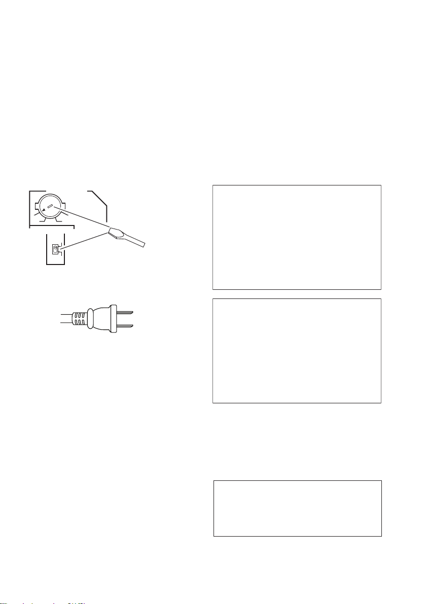
T
Voltage selector
Y
ou can find the voltage selector switch on the rear
panel of multi-voltage models.
The factory setting for the voltage selector is 220 V.
Please set it to the correct voltage for your country
or region.
• Saudi Arabia operates on 127 V and 220 V mains
voltage. Please set to the correct voltage before using.
• For Taiwan, please set to 110 V before using.
• For Mexico, please set to 120 V to 127 V before using.
Before changing the voltage, disconnect the AC power
cord. Use a medium size screwdriver to change the
voltage selector switch.
TWO VOLTAGE SELECTORS
230
-
220V
110V
For Taiwan exclusively
aiwanese two pin flat-bladed plug
240V
-
127V
120
110V
120
-
127V
220V
-
240V
230
Medium-size screwdriver
VENTILATION CAUTION
When installing this unit, make sure to leave space
around the unit for ventilation to improve heat
radiation (at least 40 cm at top, 10 cm at rear, and
20 cm at each side).
WARNING
Slots and openings in the cabinet are provided for
ventilation to ensure reliable operation of the
product, and to protect it from overheating. To
prevent fire hazard, the openings should never be
blocked or covered with items (such as newspapers,
table-cloths, curtains) or by operating the
equipment on thick carpet or a bed.
WARNING
This equipment is not waterproof. To prevent a fire
or shock hazard, do not place any container filed
with liquid near this equipment (such as a vase or
flower pot) or expose it to dripping, splashing, rain
or moisture.
D3-4-2-1-5_En
D3-4-2-1-7b_A_En
D3-4-2-1-3_A_En
WARNING
To prevent a fire hazard, do not place any naked
flame sources (such as a lighted candle) on the
equipment.
WARNING
Before plugging in for the first time, read the following
D3-4-2-1-7a_A_En
section carefully.
The voltage of the available power supply differs
according to country or region. Be sure that the
power supply voltage of the area where this unit
will be used meets the required voltage (e.g., 230 V
or 120 V) written on the rear panel. D3-4-2-1-4_A_En
CAUTION
The STANDBY/ON switch on this unit will not
completely shut off all power from the AC outlet.
Since the power cord serves as the main disconnect
device for the unit, you will need to unplug it from
the AC outlet to shut down all power. Therefore,
make sure the unit has been installed so that the
power cord can be easily unplugged from the AC
outlet in case of an accident. To avoid fire hazard,
the power cord should also be unplugged from the
AC outlet when left unused for a long period of time
(for example, when on vacation).
If the AC plug of this unit does not match the AC
outlet you want to use, the plug must be removed
and appropriate one fitted. Replacement and
mounting of an AC plug on the power supply cord of
this unit should be performed only by qualified
service personnel. If connected to an AC outlet, the
cut-off plug can cause severe electrical shock. Make
sure it is properly disposed of after removal.
The equipment should be disconnected by removing
the mains plug from the wall socket when left
unused for a long period of time (for example, when
on vacation).
D3-4-2-2-1a_A_En
Operating Environment
Operating environment temperature and humidity:
+5 ºC to +35 ºC (+41 ºF to +95 ºF); less than 85 %RH
(cooling vents not blocked)
Do not install this unit in a poorly ventilated area, or in
locations exposed to high humidity or direct sunlight (or
strong artificial light)
This product is for general household purposes. Any
failure due to use for other than household purposes
(such as long-term use for business purposes in a
restaurant or use in a car or ship) and which
requires repair will be charged for even during the
warranty period.
D3-4-2-1-7c_A_En
K041_En

Contents
01 Before you start
Checking what’s in the box
Loading the batteries
Operating range of remote control unit
Installing the receiver
02 5 minute guide
Introduction to home theater
Listening to Surround Sound
Using the Quick Setup
Automatically setting up for surround sound
(MCACC)
. . . . . . . . . . . . . . . . . . . . . . . . . . . . 10
Other problems during Auto MCACC
03 Connecting up
Making cable connections
Analog audio cables
Digital audio cables
Video cables
Connecting a TV and DVD player
Connecting the multichannel analog
outputs
Connecting a satellite receiver or other digital
set-top box
Connecting other audio components
About the WMA9 Pro decoder
Connecting other video components
Using the component video jacks
Connecting to the front panel video
terminal
Connecting to the front panel audio mini
jack
Connecting antennas
Using external antennas
Connecting the speakers
Speaker terminals
Hints on speaker placement
Speaker placement diagrams
. . . . . . . . . . . . . . . . . . . . . . . . 12
. . . . . . . . . . . . . . . . . . . . . . . . . . . . 14
. . . . . . . . . . . . . . . . . . . . . . . . . . 14
. . . . . . . . . . . . . . . . . . . . . . . . . . . 17
. . . . . . . . . . . . . . . . . . . . . . . . . . . . . . 17
04 Controls and displays
Front panel
Display
Remote control (VSX-817)
Remote control (VSX-517)
. . . . . . . . . . . . . . . . . . . . . . . . . . 22
. . . . . . . . . . . . . . . . . . . . . . . . . . . . . 24
05 Listening to your system
Auto playback
Listening in surround sound
Using the Advanced surround effects
Setting the effect options
Listening in stereo
Using Front Stage Surround Advance
Using Stream Direct
. . . . . . . . . . . . . . . . . . . . . . . . 31
. . . . . . . . . . . . . . . . . . . . . 33
. . . . . . . . . . . . . . . 6
. . . . . . . . . . . . . . . . . . . 6
. . . . . . 7
. . . . . . . . . . . . . . . . . . . 7
. . . . . . . . . . . . . 8
. . . . . . . . . . . . . 8
. . . . . . . . . . . . . . . . . . 9
. . . . . 11
. . . . . . . . . . . . . . 12
. . . . . . . . . . . . . . . . . . 12
. . . . . . . . . . . . . . . . . . 12
. . . . . . . . . 13
. . . . . . 15
. . . . . . . . . . 15
. . . . . . 16
. . . . . . . . 16
. . . . . . . . . . . . . . . . . . 18
. . . . . . . . . . . . . . . 18
. . . . . . . . . . . . . . . 19
. . . . . . . . . . . . . . . . . . . 20
. . . . . . . . . . . . 20
. . . . . . . . . . . 21
. . . . . . . . . . . . . . . 25
. . . . . . . . . . . . . . . 28
. . . . . . . . . . . . . 31
. . . . 32
. . . . . . . . . . . . . . 32
. . . . . . 33
. . . . . . . . . . . . . . . . . . . 34
Listening with Acoustic Calibration EQ
Choosing the input signal
Using surround back channel processing
Using Virtual Surround Back (VSB)
Using Phase Control
Using Midnight and Loudness
Enhancing dialog
Using the tone controls
Using the Sound Retriever
Playing other sources
Selecting the multichannel analog inputs
Selecting the front audio inputs
. . . . . . . . . . . . . . . 34
. . . . . . . . . . . . . . . . . . . 36
. . . . . . . . . . . . 37
. . . . . . . . . . . . . . . . . . . . . 37
. . . . . . . . . . . . . . . . . 37
. . . . . . . . . . . . . . . 37
. . . . . . . . . . . . . . . . . . 37
. . . . . 34
. . . 35
. . . . . . . . 35
. . . 38
. . . . . . . . . . 38
06 The System Setup menu
Using the System Setup menu . . . . . . . . . . . 39
Surround back speaker setting . . . . . . . . . . . 39
Manual MCACC speaker setup . . . . . . . . . . . 40
Fine Channel Level . . . . . . . . . . . . . . . . . . . 40
Fine Speaker Distance . . . . . . . . . . . . . . . . 41
Acoustic Calibration EQ . . . . . . . . . . . . . . . 41
Manual speaker setup . . . . . . . . . . . . . . . . . . 43
Speaker setting. . . . . . . . . . . . . . . . . . . . . . 43
Crossover network . . . . . . . . . . . . . . . . . . . 44
Channel level . . . . . . . . . . . . . . . . . . . . . . . 44
Speaker Distance . . . . . . . . . . . . . . . . . . . . 45
The Input Assign menu . . . . . . . . . . . . . . . . . 45
The Other setup menu. . . . . . . . . . . . . . . . . . 46
Dynamic Range Control Setup . . . . . . . . . . 46
Dual Mono Setup . . . . . . . . . . . . . . . . . . . . 46
LFE Attenuator Setup . . . . . . . . . . . . . . . . . 46
07 Using the tuner
Listening to the radio. . . . . . . . . . . . . . . . . . . 47
Tuning directly to a station . . . . . . . . . . . . . 47
Saving station presets . . . . . . . . . . . . . . . . . . 47
Naming station presets. . . . . . . . . . . . . . . . 47
Listening to station presets. . . . . . . . . . . . . 48
Changing the frequency step. . . . . . . . . . . . . 48
08 Making recordings
Making an audio or a video recording . . . . . . 49
09 Controlling the rest of your
system
Setting the remote to control other
components . . . . . . . . . . . . . . . . . . . . . . . . . 50
Selecting preset codes directly . . . . . . . . . . . 50
Direct function . . . . . . . . . . . . . . . . . . . . . . . 51
Clearing all the remote control settings. . . . . 51
Controls for TVs . . . . . . . . . . . . . . . . . . . . . . . 52
Controls for other components . . . . . . . . . . . 53
Preset Code List . . . . . . . . . . . . . . . . . . . . . . 55

10 Other connections
Second Zone speaker B setup
Switching the speaker system
Bi-amping your front speakers
Bi-wiring your speakers
. . . . . . . . . . . . . . . . . 57
. . . . . . . . . . . . 56
. . . . . . . . . . 56
. . . . . . . . . . . 57
11 Additional information
Troubleshooting
Resetting the main unit
Switching the speaker impedance
Power cord caution
Specifications
Cleaning the unit
. . . . . . . . . . . . . . . . . . . . . . 58
. . . . . . . . . . . . . . . . . 60
. . . . . . . . . 60
. . . . . . . . . . . . . . . . . . . . 60
. . . . . . . . . . . . . . . . . . . . . . . . 61
. . . . . . . . . . . . . . . . . . . . 62
English Italiano Français
Nederlands
EspañolDeutsch
Before you start01
Chapter 1:
Before you start
Checking what’s in the box
Please check that you’ve received the following
supplied accessories:
• AM loop antenna
• FM wire antenna
• AA size IEC R6 dry cell batteries (to confirm
system operation) x2
• Remote control
• Setup microphone
• Power cords (make sure you use the
correct cord for your country/region):
VSX-517/817-K (black models)
Round 2-pin type and Australian type
VSX-517/817-S (silver models)
Round 2-pin type, flat blade 2-pin type and
UK 3-pin type (Except Australian model)
• Power plug adaptor
• J-shaped plug
• These operating instructions
(VSX-817 model only)
(VSX-517/817-K only)
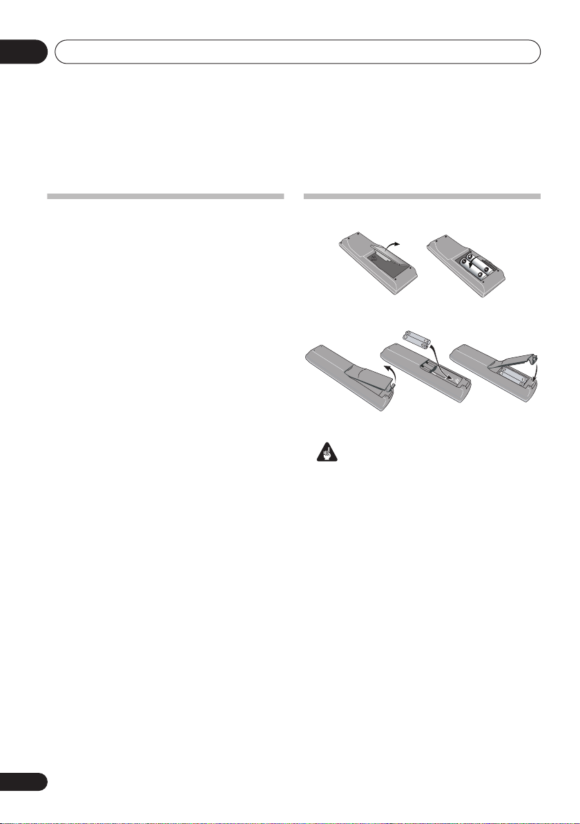
Loading the batteries
Illustration shows the VSX-517 model
Illustration shows the VSX-817 model
Important
Incorrect use of batteries may result in such
hazards as leakage and bursting. Observe the
following precautions:
• Never use new and old batteries together.
• Insert the plus and minus sides of the
batteries properly according to the marks
in the battery case.
• Batteries with the same shape may have
different voltages. Do not use different
batteries together.
• When disposing of used batteries, please
comply with governmental regulations or
environmental public instruction’s rules
that apply in your country or area.
6
En

Before you start
01
WARNING
• Do not use or store batteries in direct
sunlight or other excessively hot place,
such as inside a car or near a heater. This
can cause batteries to leak, overheat,
explode or catch fire. It can also reduce the
life or performance of batteries.
Operating range of remote
control unit
The remote control has a range of about 7
meters. It may not work properly if:
• There are obstacles between the remote
control and the receiver’s remote sensor.
• Direct sunlight or fluorescent light is
shining onto the remote sensor.
• The receiver is located near a device that is
emitting infrared rays.
• The receiver is operated simultaneously
with another infrared remote control unit.
Installing the receiver
• When installing this unit, make sure to put
it on a level and stable surface.
Don’t install it on the following places:
– on a color TV (the screen may distort)
– near a cassette deck (or close to a device that
gives off a magnetic field). This may interfere
with the sound.
– in direct sunlight
– in damp or wet areas
– in extremely hot or cold areas
– in places where there is vibration or other
movement
– in places that are very dusty
– in places that have hot fumes or oils (such as
a kitchen)
English
Deutsch
Français
Italiano
Nederlands
Español
En
7
5 minute guide02
Chapter 2:
5 minute guide
Introduction to home theater
Home theater refers to the use of multiple
audio tracks to create a surround sound effect,
making you feel like you’re in the middle of the
action or concert. The surround sound you get
from a home theater system depends not only
on your speaker setup, but also on the source
and the sound settings of the receiver.
This receiver will automatically decode
multichannel Dolby Digital, DTS, or Dolby
Surround sources according to your speaker
setup. In most cases, you won’t have to make
changes for realistic surround sound, but
other possibilities (like listening to a CD with
multichannel surround sound) are explained in
Listening to your system
Listening to Surround Sound
This receiver was designed with the easiest
possible setup in mind, so with the following
quick setup guide, you should have your
system hooked up for surround sound in no
time at all. In most cases, you can simply leave
the receiver in the default settings.
• Be sure to complete all connections before
connecting to an AC power source.
1 Connect your TV and DVD player.
See
Connecting a TV and DVD player
to do this. For surround sound, you’ll want to
hook up using a digital connection from the
DVD player to the receiver.
2 Connect your speakers and place them for
optimal surround sound.
See
Connecting the speakers
on page 31.
on page 13
on page 19.
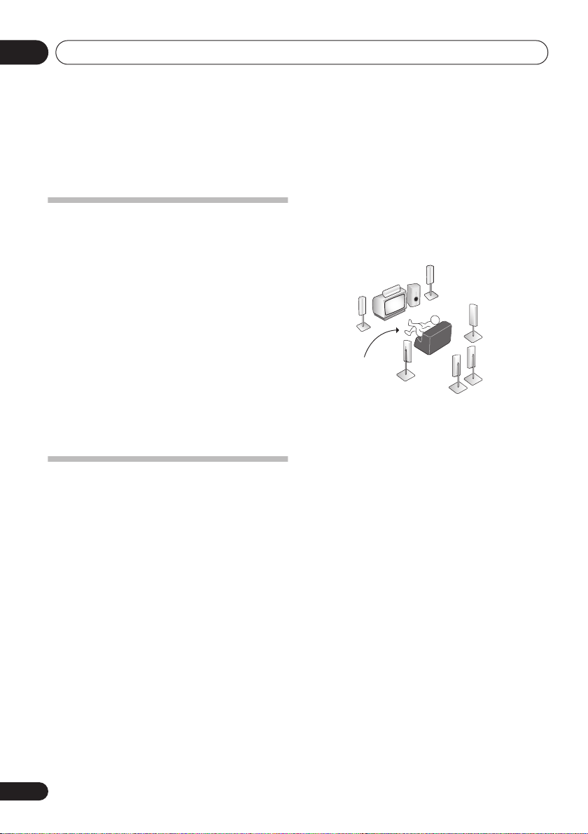
Where you place the speakers will have a big
effect on the sound. Place your speakers as
shown below for the best surround sound
effect. Also see
Hints on speaker placement
on
page 20 for more on this.
Front
speaker
(R)
Subwoofer (SW)
Surround back
speaker (SBL)*
Surround
speaker (RS)
Surround
back
speaker (SBR)*
Front
speaker
(L)
Listening
position
Center
speaker
(C)
Surround
speaker (LS)
* VSX-817 model only
3 Plug in and switch on the receiver, followed
by your DVD player, subwoofer and TV.
Make sure you’ve set the video input on your TV
to this receiver. Check the manual that came
with the TV if you don’t know how to do this.
4
VSX-517 model –
Press QUICK SETUP on the
front panel to specify your speaker setup,
room size and listening position.
Use the
to confirm your selection. See
Setup
MULTI JOG
dial to select and
below for more on this.
VSX-817 model –
Use the display automatic
ENTER
Using the Quick
MCACC setup to set up your system.
See
Automatically setting up for surround
sound (MCACC)
below for more on this.
5 Play a DVD, and adjust the volume.
Make sure that
DVD
is showing in the
receiver’s display, indicating that the DVD
input is selected. If it isn’t, press
model)
/
DVD/LD (VSX-817 model)
DVD (VSX-517
on the remote
to set the receiver to the DVD input.
8
En
5 minute guide
02
There are several other sound options you can
select. See
for more on this.
menu
Listening to your system
1
See also
on page 31
The System Setup
on page 39 for more setup options.
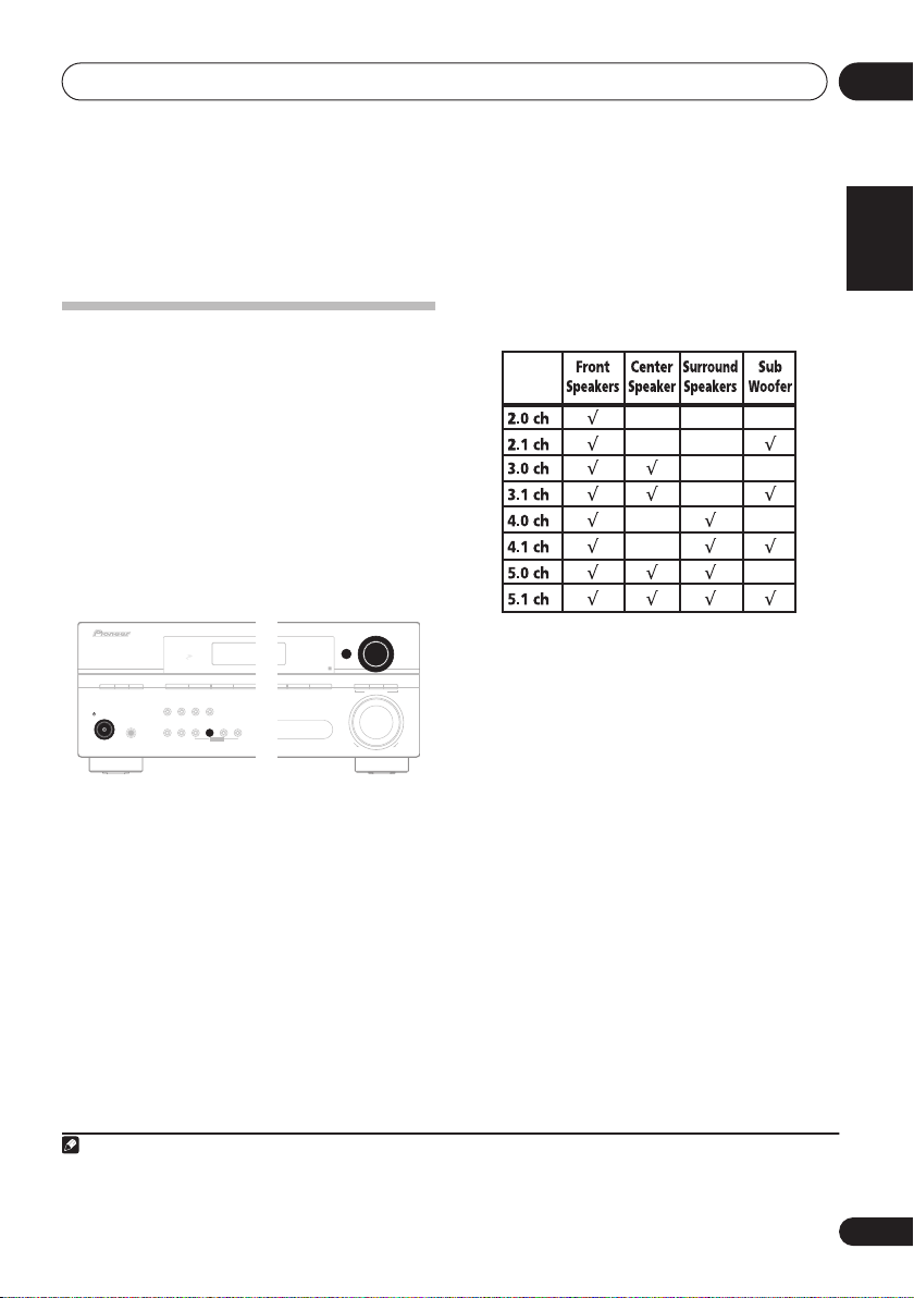
2.1ch – 3.1ch – 4.1ch – 5.1ch
If you selected NO for the subwoofer setting in
step 3, the following choices are available:
2.0ch – 3.0ch – 4.0ch – 5.0ch
• Check the table below to find the speaker
Using the Quick Setup
setup that corresponds with your system.
VSX-517 model only
You can use the Quick Setup to get your
system up and running with just a few button
presses. The receiver automatically makes the
necessary settings after you have selected your
speaker setup, room size and listening
position.
If you want to make more specific settings,
refer to
The System Setup menu
on page 39.
Use the front panel controls for the steps
below.
ENTER
STEREO/
TUNING
STATION
STANDARD
F.S.SURR
LISTENING MODE
STANDBY/ON
PHASE
CONTROL
DIALOGUE
PHASE
AUTO SURR/
ENHANCEMENT
CONTROL
PHONES
DVD 5.1 TV/SAT
DVD/LD
DIRECT
SOUND
RETRIEVER
SIGNAL
SELECT
DVR/VCR
MIDNIGHT/
VSB
LOUDNESS
MODE
TONE
QUICK
TUNER
SETUP
EDIT
SETUP RETURN
DIMMER
MULTI JOG
1 If the receiver is off, press
STANDBY/ON
2 Press
3 Use the
to turn the power on.
QUICK SETUP
MULTI JOG
.
dial to choose your
subwoofer setting.
Select
YES
or NO, depending on whether
you’ve connected a subwoofer.
4 Press
5 Use the
ENTER
.
MULTI JOG
dial to choose your
speaker setup.
If you selected
YES
for the subwoofer setting in
step 3, the following choices are available:
VSX-517
MULTI JOG
ADVANCED
SURROUND
UPDOWN
6 Press
7 Use the
room size.
MASTER
VOLUME
Depending on the distance of your speakers
ENTER
.
MULTI JOG
dial to choose your
from the listening position, choose between
small, medium, or large (
S, M
an average-sized room.
8 Press ENTER.
9 Use the
MULTI JOG
dial to choose your
listening position.
You can cycle between the following choices:
•
FWD
– If you are nearer to the front
speakers than the surround speakers
•
MID
– If you are equal distance from the
front and surround speakers
•
BACK
– If you are nearer to the surround
speakers than the front speakers
10 Press
ENTER
to confirm your setup.
The display shows the speaker setup, room size
or L), M being
and listening position that you have selected.
Note
1 Depending on your DVD player or source discs, you may only get digital 2 channel stereo and analog sound. In this case, the
listening mode must be set to
do this) if you want multichannel surround sound.
STANDARD
(it should already be set – see
Listening in surround sound
on page 31 if you need to
English
Deutsch
Français
Italiano
Nederlands
Español
En
9
5 minute guide02
Automatically setting up for
surround sound (MCACC)
VSX-817 model only
The Auto Multi-Channel Acoustic Calibration
(MCACC) setup measures the acoustic
characteristics of your listening area, taking
into account ambient noise, speaker size and
distance, and tests for both channel delay and
channel level. After you have set up the
microphone provided with your system, the
receiver uses the information from a series of
test tones to optimize the speaker settings and
equalization for your particular room.
Important
• The Auto MCACC Setup will overwrite any
existing speaker settings you’ve made.
• Make sure the headphones are unplugged.
Caution
• The test tones used in the Auto MCACC
Setup are output at high volume.
RECEIVER CONTROL
ONE TOUCH
RECEIVER
DVD/LD
CD-R/TAPE
CD
AUTO SURR
INPUT SELECT
MULTI CONTROL
TV/SAT
FM AM
STEREO/
STANDARD
F.S.SURR
DVR/VCR
SOURCE
TV CTRL
F.AUDIO
RECEIVER
ADV.SURR
TOP MENU
GUIDE
SUBTITLE
COPY
ST
SETUP
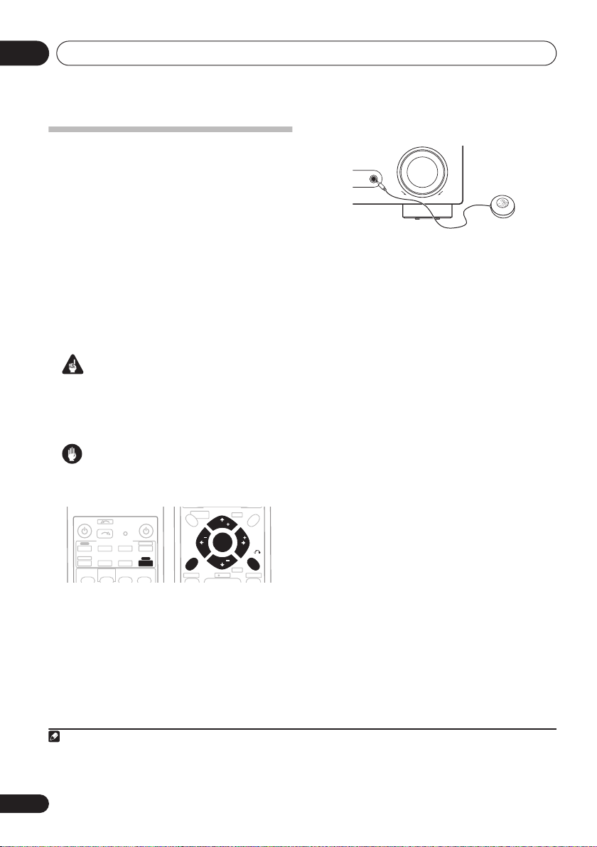
1 Connect the microphone to the MCACC/
AUDIO IN jack on the front panel.
Make sure there are no obstacles between the
speakers and the microphone.
Push down on the
the
MCACC/AUDIO IN
PUSH OPEN
jack.
MENU
+
CH
TUNE
T.EDIT
ST
ENTER
RETURN
TUNE
-
CH
REC
AUDIO
tab to access
MASTER
MCACC/
AUDIO IN
VOLUME
UPDOWN
If you have a tripod, use it to place the
microphone so that it’s about ear level at your
normal listening position. Otherwise, place the
microphone at ear level using a table or a chair.
2 If the receiver is off, press
RECEIVER
to
turn the power on.
3 If you have a subwoofer, turn it on.
4 Press
RECEIVER
then press the
• Press
SETUP
System Setup menu.
on the remote control,
SETUP
button.
again at any time to exit the
1
5 Select ‘A. MCACC’ from the System Setup
menu then press
Make sure ‘SB NORM.’ is selected then
6
press ENTER.
2
ENTER
.
Try to be as quiet as possible after pressing
ENTER
. The system outputs a series of test
tones to establish the ambient noise level.
If the noise level is too high,
NOISY!
blinks in
the display for five seconds. To exit and check
the noise levels again, press
SETUP
(see the
notes about ambient noise below) or press
ENTER
when you’re prompted to
RETRY?.
• Do not adjust the volume during the test
tones. This may result in incorrect speaker
settings.
The system now checks the microphone and
your speaker setup.
Note
1 The receiver will automatically exit the current menu after three minutes of inactivity. If you cancel the Auto MCACC Setup at
any time, the receiver automatically exits and no settings will be made.
2• If you are planning on bi-amping your front speakers, or setting up a separate speaker system in another room, read through
Surround back speaker setting
on page 39 and make sure to connect your speakers as necessary before continuing to step 7.
10
En

5 minute guide
02
If you see an
may be a problem with your mic or the speaker
connections. Turn off the power, and check the
problem indicated by the
below), then try the auto surround setup again.
•
ERR MIC
•
ERR Fch
•
ERR Sch
connections.
•
ERR SBch
connection.
•
ERR SW
been switched on and volume on the
subwoofer is turned up.
7 When you see CHECK OK in the display,
confirm your speaker configuration.
Use
/
speaker in turn.
actual speakers connected. If the speaker
configuration displayed isn’t correct, use
(cursor left/right) to change the setting.
When you’re finished, go to the next step.
8 Select CHECK OK in the display then press
ENTER
If the display in step 7 is left untouched for 30
seconds, and the
in Step 8, the Auto MCACC Setup will start
again from the beginning.
The Auto MCACC checks the subwoofer level.
• If the subwoofer output level is too high/
low,
the display for five seconds. To exit and
check your subwoofer output level, press
SETUP
prompted to
The receiver outputs more test tones to
determine the optimum receiver settings for
speaker setting, channel level, speaker
distance, and Acoustic Calibration EQ.
Note
1• Depending on the characteristics of your room, sometimes identical speakers with cone sizes of around 12 cm will end up
with different size settings. You can correct the setting manually using the
• The subwoofer distance setting may be farther than the actual distance from the listening position. This setting should be
accurate (taking delay and room characteristics into account) and generally does not need to be changed.
2 Some older TVs may interfere with operation of the mic. You may want to switch off your TV during the Auto MCACC Setup.
ERR
message in the display, there
ERR
message (see
– Check microphone connection.
– Check front speaker connections.
– Check surround speaker
– Check surround back speaker
– Make sure the subwoofer has
(cursor up/down) to check each
YES
or NO should reflect the
.
ENTER
button is not pressed
SW.VOL.DWN/SW.VOL.UP
or simply press
RETRY?
ENTER
.
when you’re
/
blinks in
9 The Auto MCACC Setup has finished!
The front panel MCACC indicator lights to
show the surround settings are complete.
The settings made in the Auto MCACC Setup
should give you excellent surround sound
from your system, but it is also possible to
adjust these settings manually using the
System Setup menu (starting on page 39).
Optionally, when you see
/
(cursor up/down) to select one of the
following options then press
/
(cursor up/down) to check the settings:
CHK SP
•
•
•
•
– Check the size and number of
speakers you’ve connected (see page 43
for more on this)
CHK DIST.
speakers from the listening position (see
page 45 for more on this)
CHK LEVEL
your speaker system (see page 44 for
more on this)
CHK EQ
ALIGN
frequency balance of your speaker system
based on the acoustic characteristics of
your room (see page 41 for more on this)
– Check the distance of your
– Check the overall balance of
– Select either
to check the adjustments to the
10 When you’re finished, select
SKIP?
you can press
ENTER
ALL CH
‘SKIP?’
1
, and use
or
F
to
go back to the System Setup menu.
• Remember to disconnect the microphone
after completing the Auto MCACC Setup.
Other problems during Auto MCACC
If the room environment is not optimal for the
Auto MCACC Setup (too much background
noise, echo off the walls, obstacles blocking
the speakers from the microphone) the final
settings may be incorrect. Check for household
appliances (air conditioner, fridge, fan, etc.),
that may be affecting the environment and
switch them off if necessary.
instructions showing in the front panel display,
please follow them.
Speaker setting
on page 43.
2
If there are any
English
Deutsch
Français
Italiano
Nederlands
Español
11
En
Connecting up03
S
Chapter 3:
Connecting up
Making cable connections
Make sure not to bend the cables over the top
of this unit. If this happens, the magnetic field
produced by the transformers in this unit may
cause a humming noise from the speakers.
Important
• Before making or changing any connections,
switch off the power and disconnect the
power cord from the AC outlet.
• Before unplugging the power cord, switch
the power into standby.
Analog audio cables
Use stereo RCA phono cables to connect
analog audio components. These cables are
typically red and white, and you should
connect the red plugs to R (right) terminals
and white plugs to L (left) terminals.
Analog audio cables
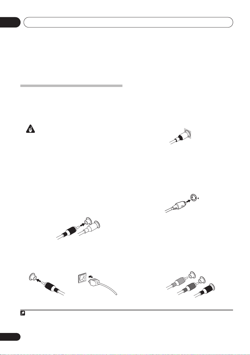
Video cables
Standard RCA video cables
These cables are the most common type of
video connection and should be used to
connect to the composite video terminals. They
have yellow plugs to distinguish them from
cables for audio.
tandard RCA video cable
S-video cables
VSX-817 model only
S-video cables give you a clearer picture
reproduction than standard RCA video cables
by sending separate signals for the luminance
and color.
S Video
Component video cables
Right (red)
Left (white)
Digital audio cables
Commercially available coaxial digital audio
cables or optical cables should be used to
connect digital components to this receiver.
Coaxial digital audio cable Optical cable
Note
1• When connecting optical cables, be careful when inserting the plug not to damage the shutter protecting the optical socket.
• When storing optical cable, coil loosely. The cable may be damaged if bent around sharp corners.
• You can also use a standard RCA video cable for coaxial digital connections.
Use component video cables to get the best
possible color reproduction of your video
source. The color signal of the TV is divided into
the luminance (
Y
) signal and the color (
PR) signals and then output. In this way,
interference between the signals is avoided.
1
Component video cables
Green (Y)
Blue (P
B
)
Red (P
R
)
PB and
12
En
Connecting up
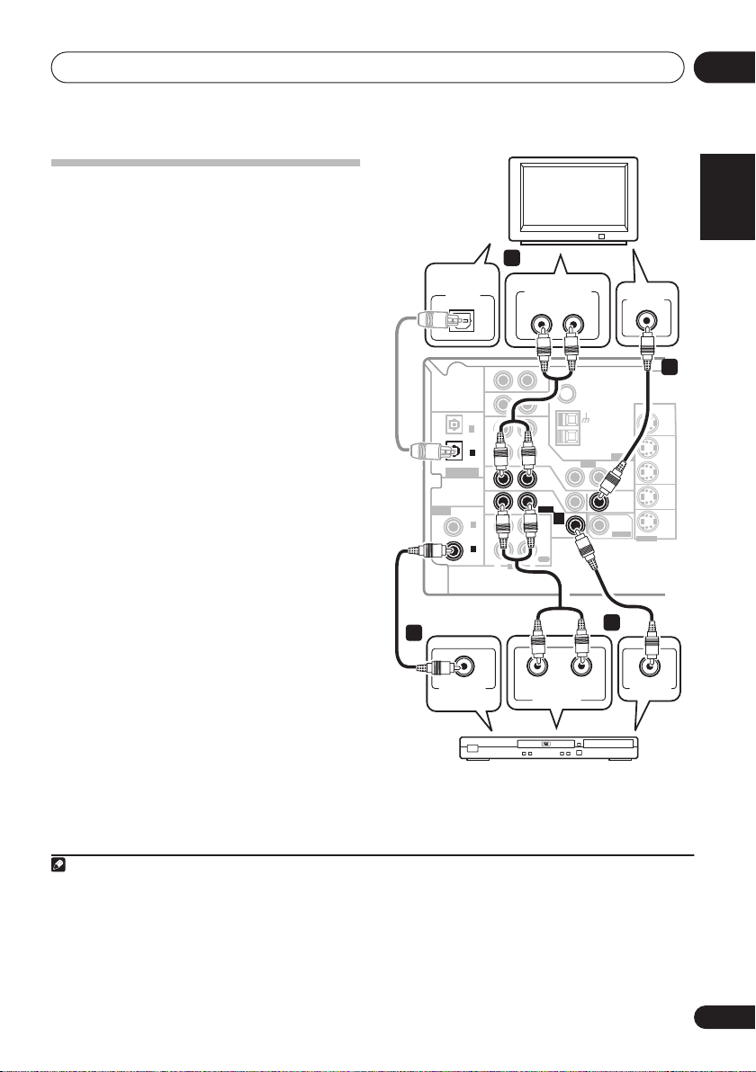
Connecting a TV and DVD player
This page shows you how to connect your DVD
player and TV to the receiver.
1 Connect a coaxial digital audio output on
your DVD player to the DIGITAL COAX 1
(DVD/LD) input on this receiver.
Use a coaxial digital audio cable for the
connection.
2 Connect the composite video output and
the stereo analog audio outputs
DVD player to the DVD/LD inputs on this
receiver.
Use a standard RCA video cable3 and a stereo
RCA phono cable for the connection.
• If your DVD player has multichannel
3 Connect the analog audio outputs from
your TV to the TV/SAT inputs on this receiver.
This will allow you to play the sound from the
TV’s built-in tuner. Use a stereo RCA phono
cable to do this.
• If your TV has a built-in digital decoder, you
4 Connect the MONITOR OUT video jack on
this receiver to a video input on your TV.
Use a standard RCA video cable to connect to
the composite video jack.
1
2
on your
analog outputs, see
multichannel analog outputs
Connecting the
below for how
to connect it.
can also connect an optical digital audio
output from your TV to the
(CD)
input on this receiver. Use an optical
cable for the connection.
DIGITAL OPT 1
4
5
The illustration shows the VSX-817, but
connections for the VSX-517 are the same.
VSX-817
1
DIGITAL
AUDIO OUT
OPTICAL
(
TV/ SAT
(CD)
ASSIGNABLE
DIGITAL IN
ASSIGNABLE
DIGITAL IN
COAXIAL
DIGITAL OUT
DVD player
OPT
)
OPT
COAX
(
DVR/VCR
COAX
(
DVD/LD
03
English
3
ANALOG AUDIO OUT
AUX
IN
IN
2
1
2
)
1
)
CD
DVR/
IN
VCR
OUT
TV/
IN
SAT
DVD
/LD
FRONT
IN
PLAY
CD-R
IN
/TAPE
/MD
REC
OUT
R
L
AUDIO
AUDIORL
ANALOG OUT
TV
FM UNBAL
Ω
75
AM
LOOP
VIDEO
ANTENNA
OUT
MONITOR
OUT
SUB
WOOFER
PREOUT
VIDEO IN
MONITOR OUT
S-VIDEO
IN
IN
IN
LR
IN
IN
D V D
5.1CH
INPUT
IN
Deutsch
Français
4
OUT
Italiano
DVR/
VCR
TV/
SAT
DVD
/LD
Nederlands
2
Español
VIDEO OUT
Note
1 If your DVD player only has an optical digital output, you can connect it to the optical input on this receiver using an optical
cable. When you set up the receiver you’ll need to tell the receiver which input you connected the player to (see
menu
on page 45).
2 This connection will allow you to make analog recordings from your DVD player.
3•
VSX-817 model only –
• If your player also has a component video output, you can connect this too. See
4 In this case, you’ll need to tell the receiver which digital input you connected the TV to (see
5•
VSX-817 model only –
• See
Using the component video jacks
For better quality, you can also connect with S-video using the
For better quality, you can also connect with S-video using the
on page 16 to use the component video outputs to connect this receiver to your TV.
Using the component video jacks
S-VIDEO DVD/LD
The Input Assign menu
S-VIDEO MONITOR OUT
The Input Assign
jack.
on page 16.
on page 45).
jack.
13
En
Connecting up03
T
R
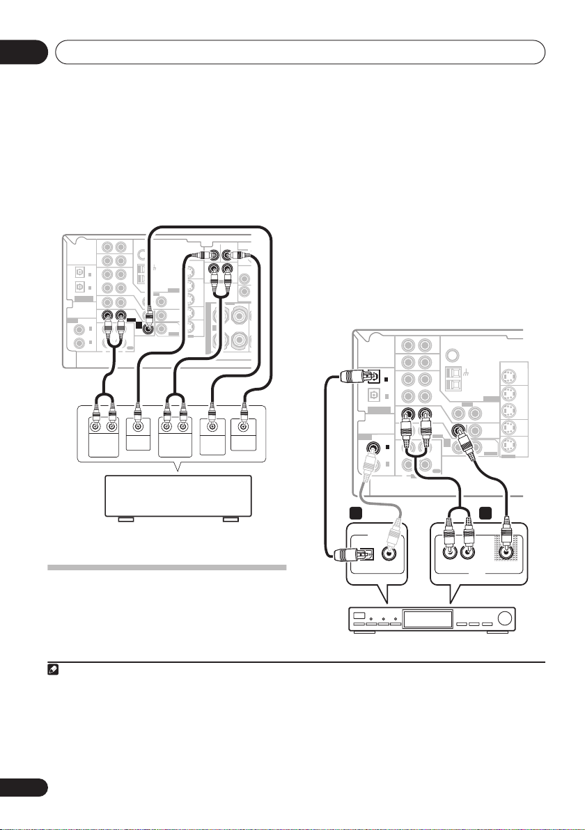
Connecting the multichannel analog
outputs
For DVD Audio and SACD playback, your DVD
player may have 5.1 channel analog outputs. In
this case, you can connect them to the multichannel
inputs of the receiver as shown below.
1 Connect a set of audio/video outputs on
the set-top box component to the TV/SAT
AUDIO and VIDEO inputs on this receiver.
Use a stereo RCA phono cable for the audio
connection and a standard RCA video cable for
the video connection.
1
3
2
2 If your set-top box has a digital output,
VSX-817
IN
IN
OPT
2
(
)
TV/ SAT
IN
OPT
1
OUT
(CD)
ASSIGNABLE
DIGITAL IN
IN
ASSIGNABLE
IN
DIGITAL IN
COAX
2
(
)
DVR/VCR
IN
COAX
1
(
)
DVD/LD
OUT
R
AUDIO
RL RL
FRONT
OUTPUT
DVD/multi-channel decoder
L
AUX
CD
DVR/
VCR
TV/
SAT
DVD
/LD
FRONT
PLAY
CD-R
/TAPE
/MD
REC
CENTER
OUTPUT
SUB
CEN-
WOOFER
TER
FM UNBAL
Ω
75
MONITOR OUT
AM
LOOP
VIDEO
IN
IN
D V D
5.1CH
INPUT
IN
ANTENNA
OUT
MONITOR
OUT
SUB
WOOFER
PREOUT
SURROUND
OUTPUT
S-VIDEO
OUT
IN
IN
IN
SIRIUS IN
(
D
Y
SURROUND
LR
DVD 5.1CH INPUT
DVR/
VCR
TV/
SAT
DVD
/LD
WOOFER
OUTPUT
MONI
FRONT
RL
S
P
E
A
A
K
E
R
S
SUB
VIDEO
OUTPUT
connect it to a digital input on this receiver.
VSX-817 model
connection.
VSX-517 model
DIGITAL OPT 1 (CD)
DIGITAL COAX 2 (DVR/VCR)
– Use an optical cable for the
4
– For example, connect to the
for optical input or the
for coaxial input.
VSX-817
AUX
(
TV/ SAT
ASSIGNABLE
DIGITAL IN
)
(CD)
ASSIGNABLE
DIGITAL IN
COAX
(
DVR/VCR
COAX
(
DVD/LD
IN
IN
OPT
2
IN
OPT
1
OUT
IN
IN
2
)
IN
1
)
OUT
R
AUDIO
FM UNBAL
Ω
75
LOOP
AM
VIDEO
ANTENNA
OUT
MONITOR
OUT
SUB
WOOFER
PREOUT
MONITOR OUT
OUT
IN
IN
IN
S-VIDEO
DVR/
VCR
TV/
SAT
DVD
/LD
CD
DVR/
VCR
IN
TV/
SAT
IN
DVD
/LD
FRONT
D V D
5.1CH
INPUT
PLAY
IN
CD-R
/TAPE
/MD
REC
L
with multi-channel analog
output jacks
The illustration shows the VSX-817, but
2 1
DIGITAL OUT
connections for the VSX-517 are the same.
L
OPTICAL COAXIAL
VIDEOAUDIOR
AV OUT
Connecting a satellite receiver
or other digital set-top box
Satellite and cable receivers, and terrestrial
digital TV tuners are all examples of so-called
‘set-top boxes’.
Note
1 The multichannel input can only be used when
2 If you’ve already connected your TV to the
which input you connected the set-top box to.
3•
VSX-817 model only –
• See
Using the component video jacks
4 If your satellite/cable receiver doesn’t have a digital audio output, omit this step. If it only has a coaxial digital output, you can
connect it to one of the coaxial inputs on this receiver using a coaxial digital audio cable. When you set up the receiver you’ll
need to tell the receiver which input you connected the set-top box to (see
5 In this case, you’ll need to tell the receiver which digital input you connected the TV to (see
For better quality, you can also connect with S-video using the
TV/SAT
DVD 5.1 ch
is selected (see page 38).
inputs, simply choose another input. However, you’ll need to remember
on page 16 if your set-top box also has a component video output.
STB
S-VIDEO TV/SAT
The Input Assign menu
The Input Assign menu
jack.
on page 45).
on page 45).
5
14
En
Connecting up
03
The illustration shows the VSX-817, but
connections for the VSX-517 are the same.
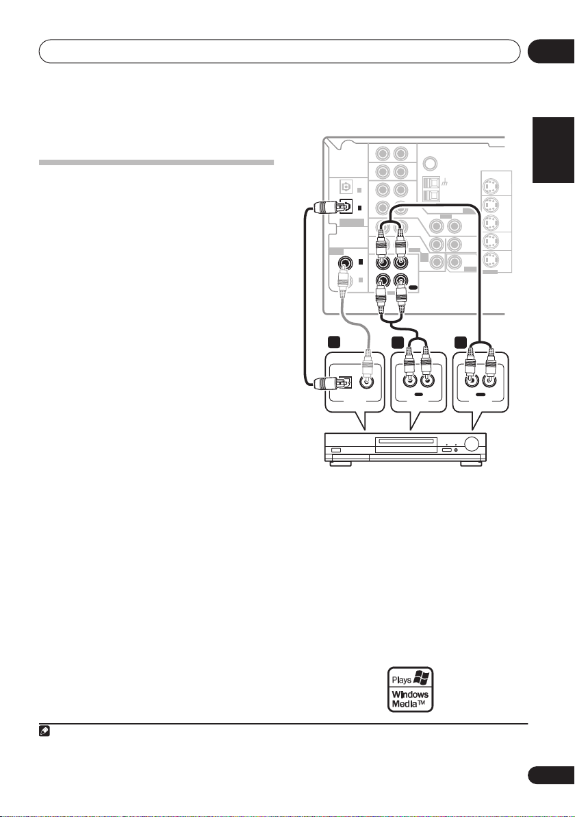
Connecting other audio
components
The number and kind of connections depends
on the kind of component you’re connecting.
Follow the steps below to connect a CD-R, MD,
DAT, tape recorder or other audio component.
1 If your component has a digital output,
connect this to a digital input on the receiver.
The example shows an optical connection to
the
DIGITAL OPT 1 (CD)
input.
2 If necessary, connect the analog audio
outputs of the component to a set of spare
audio inputs on this receiver.
You’ll need to make this connection for
components without a digital output, or if you
want to record from a digital component. Use a
stereo RCA phono cable as shown.
3 If you’re connecting a recorder, connect
the analog audio outputs (REC) to the analog
audio inputs on the recorder.
The example shows an analog connection to
the
CD-R/TAPE/MD
analog output jack using
a stereo RCA phono cable.
1
VSX-817
AUX
(
TV/ SAT
(CD)
ASSIGNABLE
DIGITAL IN
ASSIGNABLE
DIGITAL IN
1
OPTICAL COAXIAL
DIGITAL OUT
)
(
DVR/VCR
(
OPT
OPT
COAX
COAX
DVD/LD
IN
IN
2
IN
1
OUT
IN
IN
2
)
IN
1
)
OUT
R
AUDIO
3 2
CD
DVR/
VCR
CD-R
/TAPE
L
R L
TV/
SAT
DVD
/LD
FRONT
PLAY
/MD
REC
AUDIO IN
FM UNBAL
Ω
75
AM
LOOP
VIDEO
IN
IN
D V D
5.1CH
INPUT
IN
IN
REC
ANTENNA
OUT
MONITOR
OUT
SUB
WOOFER
PREOUT
R
AUDIO OUT
MONITOR OUT
S-VIDEO
OUT
L
PLAY
OUT
DVR/
VCR
IN
TV/
SAT
IN
DVD
/LD
IN
CD-R, MD, DAT, Tape recorder, etc.
The illustration shows the VSX-817, but
connections for the VSX-517 are the same.
About the WMA9 Pro decoder
This unit has an on-board Windows Media®
Audio 9 Professional (WMA9 Pro) decoder, so
it is possible to playback WMA9 Pro-encoded
audio using a coaxial or optical digital
connection when connected to a WMA9 Procompatible player. However, the connected
DVD player, set-top box, etc. must be able to
output WMA9 Pro format audio signals
through a coaxial or optical digital output.
English
Deutsch
Français
Italiano
Nederlands
Español
Note
1 Note that you must connect digital components to analog audio jacks if you want to record to/from digital components (like
an MD) to/from analog components.
15
En
Connecting up03
Windows Media®, and the Windows logo are trademarks,
or registered trademarks of Microsoft Corporation in the
United States and/or other countries.
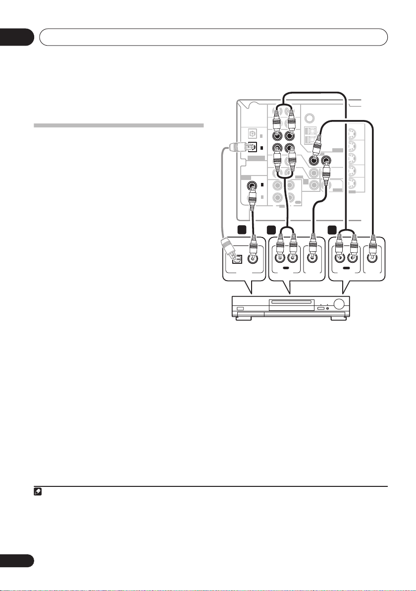
Connecting other video
components
This receiver has audio/video inputs and
outputs suitable for connecting analog or
digital video recorders, including VCRs, DVDrecorders and HDD recorders.
1 Connect a set of audio/video outputs on
the recorder to the DVR/VCR AUDIO and
VIDEO inputs on this receiver.
Use a stereo RCA phono cable for the audio
connection and a standard RCA video cable for
the video connection.
2 Connect a set of audio/video inputs on
the recorder to the DVR/VCR AUDIO and
VIDEO outputs on this receiver.
Use a stereo RCA phono cable for the audio
connection and a standard RCA video cable for
the video connection.
3 If your video component has a digital
audio output, connect it to a digital input on
this receiver.
The example shows a recorder connected to
the
DIGITAL COAX 2 (DVR/VCR)
1
2
3
input.
VSX-817
AUX
(
TV/ SAT
(CD)
ASSIGNABLE
ASSIGNABLE
DIGITAL IN
3
OPTICAL COAXIAL
DIGITAL OUT
IN
IN
OPT
2
)
IN
OPT
1
OUT
DIGITAL IN
IN
IN
COAX
2
(
)
DVR/VCR
IN
COAX
1
(
)
DVD/LD
OUT
R
AUDIO
2 1
IN
R L
REC
AUDIO IN
FM UNBAL
Ω
75
LOOP
AM
VIDEO
ANTENNA
OUT
MONITOR
OUT
SUB
WOOFER
PREOUT
OUT
R L
PLAY
AUDIO OUT
MONITOR OUT
OUT
IN
IN
IN
S-VIDEO
DVR/
VCR
TV/
SAT
DVD
/LD
VIDEO OUT
CD
DVR/
VCR
IN
TV/
SAT
IN
DVD
/LD
FRONT
D V D
5.1CH
INPUT
PLAY
IN
CD-R
/TAPE
/MD
REC
L
VIDEO IN
DVR, VCR, LD player, etc.
The illustration shows the VSX-817, but
connections for the VSX-517 are the same.
Using the component video jacks
Component video should deliver superior
picture quality when compared to composite
video. A further advantage (if your source and
TV are both compatible) is progressive-scan
video, which delivers a very stable, flicker-free
picture. See the manuals that came with your
TV and source component to check whether
they are progressive-scan video compatible.
Note
1•
VSX-817 model only –
• If your video component also has a component video output, you can connect this too. See
on page 16 for more on this.
2
VSX-817 model only –
3 If your video component doesn’t have a digital audio output, omit this step. If it only has an optical digital output, you can connect it to the optical input on this receiver using an optical cable. When you set up the receiver you’ll need to tell the receiver
which input you connected the component to (see
For better quality, you can also connect with S-video using the
For better quality, you can also connect with S-video using the
The Input Assign menu
on page 45).
S-VIDEO DVR/VCR IN
Using the component video jacks
S-VIDEO DVR/VCR OUT
16
En
jack.
jack.
Connecting up
03
Important
• If you connect any source component to
the receiver using a component video
input, you must also have your TV
connected to this receiver’s
VIDEO MONITOR OUT
COMPONENT
jacks.
1 Connect the component video outputs of
your source to a set of component video
inputs on this receiver.
Use a three-way component video cable.
2 If necessary, assign the component video
inputs to the input source you’ve connected.
This only needs to be done if you didn’t connect
according to the following defaults:
•
COMP 1
•
COMP 2
•
COMP 3
See
Assigning the component video inputs
–
–
–
DVD
TV
DVR
on
page 45.
3 Connect the COMPONENT VIDEO
MONITOR OUT jacks on this receiver to the
component video inputs on your TV or
monitor.
Use a three-way component video cable.
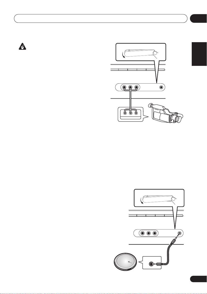
Connecting to the front panel video
terminal
VSX-817 model only
Front video connections are accessed via the
front panel using the
VIDEO
and select
standard audio/video jacks. Hook them up the
same way you made the rear panel
connections.
• Push down on the
access the front audio/video connection.
VIDEO
VIDEO
input. There are
PUSH OPEN
button. Press
tab to
MCACC/
AUDIO IN
PUSH
OPEN
FM
AM
AUX
MCACC/
AUDIO IN
FRONT AUDIO
AUDIO RLVIDEO
CD
CD-R/TAPE/MD
VIDEO
AUDIO RL
Video
camera
(etc.)
LV
R
VIDEO OUTPUT
Connecting to the front panel audio
mini jack
VSX-817 model only
Front audio connections are accessed via the
front panel using the
FRONT AUDIO
Press
input. Use a stereo mini-jack cable to connect
a digital audio player.
• Push down on the
access the front audio/video connection.
FRONT AUDIO
FRONT AUDIO
and select
PUSH OPEN
AUDIO RLVIDEO
CD-R/TAPE/MD
AUDIO RL
FM
CD
VIDEO
botton.
F.AUDIO
tab to
MCACC/
AUDIO IN
PUSH
OPEN
AM
AUX
MCACC/
AUDIO IN
English
Deutsch
Français
Italiano
Nederlands
Español
Portable CD player (etc.)
AUDIO OUT
17
En
Connecting up03
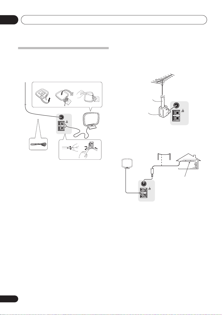
Connecting antennas
Connect the AM loop antenna and the FM wire
antenna as shown below. To improve reception
and sound quality, connect external antennas
(see
Using external antennas
fig. a fig. b fig. c
5
1 Pull off the protective shields of both AM
antenna wires.
2 Push open the tabs, then insert one wire
fully into each terminal, then release the tabs
to secure the AM antenna wires.
3 Fix the AM loop antenna to the attached
stand.
To fix the stand to the antenna, bend in the
direction indicated by the arrow (
clip the loop onto the stand (
• If you plan to mount the AM antenna to a
wall or other surface, secure the stand with
screws (
fig. c
) before clipping the loop to the
stand. Make sure the reception is clear.
4 Place the AM antenna on a flat surface
and in a direction giving the best reception.
5 Connect the FM wire antenna in the same
way as the AM loop antenna.
For best results, extend the FM antenna fully
and fix to a wall or door frame. Don’t drape
loosely or leave coiled up.
FM UNBAL
75
AM
LOOP
1
Ω
fig. b
below).
3
fig. a
).
4
2
) then
Using external antennas
To improve FM reception
Connect an external FM antenna as shown
below.
75 Ω coaxial
cable
J-shaped
plug
To improve AM reception
Connect a 5 m to 6 m length of vinyl-coated
wire to the AM antenna terminal without
disconnecting the supplied AM loop antenna.
Outdoor
antenna
5 m to 6 m
FM UNBAL
75
AM
LOOP
For the best possible reception, suspend
horizontally outdoors.
FM UNBAL
Ω
75
AM
LOOP
Indoor antenna
(vinyl-coated wire)
18
En
Connecting up
5
AUX
TWO VOLTAGE SELECTORS
0V
UT
subwoofer
l
l
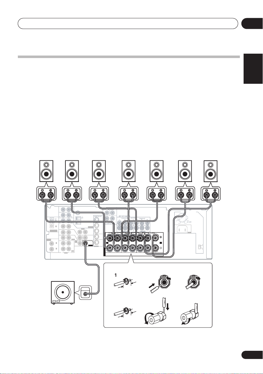
Connecting the speakers
A complete speaker setup is shown below, but everyone’s home setup will vary.
the speakers you have in the manner shown below. The receiver will work with just two stereo
speakers (the front speakers in the diagram) but using at least three
model)
speakers is recommended, and a complete setup is best for surround sound.
using a subwoofer, change the front speaker setting (see
Speaker setting
(VSX-517 model)
Make sure you connect the speaker on the right to the right terminal and the speaker on the left
to the left terminal. Also make sure the positive and negative (
+/–
) terminals on the receiver
match those on the speakers. You can use speakers with a nominal impedance between 6
16
Ω
(please see
impedance of less than 8
Switching the speaker impedance
Ω
).
on page 60 if you plan to use speakers with an
Be sure to complete all connections before connecting this unit to the AC power source.
Front speakers
LRC LSRS
Surround speakersCenter speaker
(VSX-817 model only)
Surround back speakers
SBL
Simply connect
/ five
If you’re not
on page 43) to
SBR
(VSX-817
LARGE
Ω
to
03
English
Deutsch
.
Français
Italiano
Nederlands
7
VCR
OPT
1
OUT
(CD)
ASSIGNABLE
DIGITAL IN
IN
ASSIGNABLE
IN
DIGITAL IN
COAX
2
(
)
DVR/VCR
IN
COAX
1
(
)
DVD/LD
OUT
Powered
R
AM
LOOP
IN
TV/
SAT
IN
DVD
/LD
FRONT
D V D
5.1CH
INPUT
PLAY
IN
CD-R
/TAPE
/MD
REC
L
AUDIO
OUT
ANTENNA
VIDEO
DVR/
VCR
OUT
IN
R
S
TV/
SAT
P
MONITOR
IN
OUT
E
DVD
SUB
/LD
A
A B
WOOFER
IN
PREOUT
K
S-VIDEO
E
R
S
L
VSX-517 mode
SW
INP
10 mm
VSX-817 mode
123
10 mm
The illustration shows the VSX-817, but connections for the VSX-517 are the same.
22
120 - 127V
110V
AC IN
110V
-
127V
120
220V
230
-
240V
Español
3
19
En
 Loading...