

Page 1
AUDIO/VIDEO MULTI-CHANNEL AMPLIFIER
VSA-E07
THIS MANUAL IS APPLICABLE TO THE FOLLOWING MODEL(S) AND TYPE(S).
ORDER NO.
RRV2203
Type
HY ‡
HV ‡
: Alter the wiring of the Power -supply block at the primary winding of Power -transformer referring to the "Line V oltage Selection" described
∗
in Service Manual.
Model
VSA-E07
Power Requirement
AC220-230V
AC230V
The voltage can be converted by
the following method.
AC240V,
AC240V,
∗
∗
¶ This service manual should be used together with the following manual(s):
Model No. Order No. Remarks
VSX-908RDS-G/HY RRV2166
CONTENTS
1. CONTRAST OF MISCELLANEOUS PARTS
2. PCB CONNECTION DIAGRAM
3. SCHEMATIC DIAGRAM
4. REMOTE CONTROL UNIT
PIONEER CORPORATION 4-1, Meguro 1-chome, Meguro-ku, Tokyo 153-8654, Japan
PIONEER ELECTRONICS SERVICE, INC. P.O. Box 1760, Long Beach, CA 90801-1760, U.S.A.
PIONEER ELECTRONIC (EUROPE) N.V. Haven 1087, Keetberglaan 1, 9120 Melsele, Belgium
PIONEER ELECTRONICS ASIACENTRE PTE. LTD. 253 Alexandra Road, #04-01, Singapore 159936
PIONEER CORPORATION 1999
.....................................
............................
.................................
........
2
9
10
20
T – ZZK SEPT. 1999 Printed in Japan
Page 2
VSA-E07
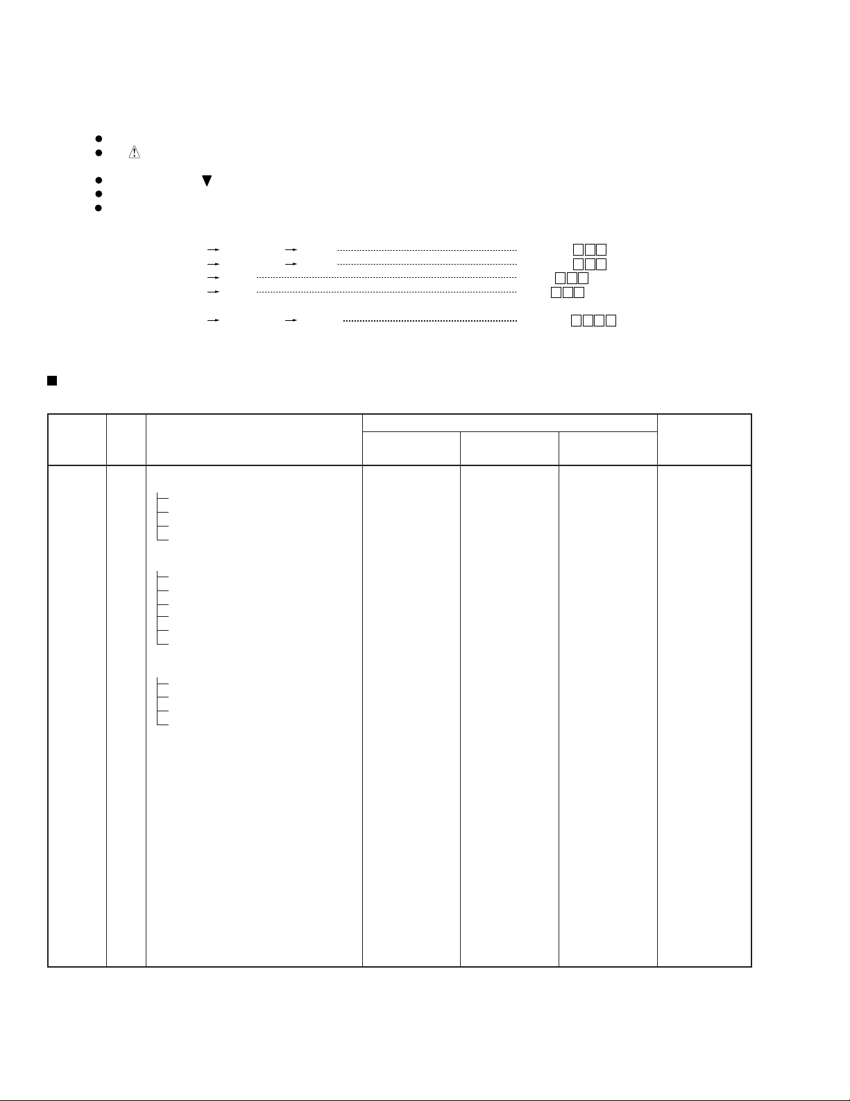
1. CONTRAST OF MISCELLANEOUS PARTS
NOTES:
CONTRAST TABLE
VSA-E07/HY, HV and VSX-908RDS-G/HY are constructed the same except for the following :
Ref. No. Mark Symbol and Description VSX-908RDS-G VSA-E07 VSA-E07 Remarks
P5-12 VIDEO ASSY AWX7422 AWX7419 AWX7419
P5-13 S-VIDEO ASSY AWX7395 AWX7308 AWX7308
P5-16 DIGITAL-I/O ASSY AWX7396 AWX7315 AWX7315
Parts marked by "NSP" are generally unavailable because they are not in our Master Spare Parts List.
The mark found on some component parts indicates the importance of the safety factor of the part.
Therefore, when replacing, be sure to use parts of identical designation.
Screws adjacent to mark on product are used for disassembly.
Reference Nos. indicate the pages and Nos. in the service manual for the base model.
When ordering resistors, first convert resistance values into code form as shown in the following examples.
Ex.1 When there are 2 effective digits (any digit apart from 0), such as 560 ohm and 47k ohm (tolerance is shown by J=5%,
and K=10%).
560
47k
0.5
1
56 x 10
47 x 103
R50
1R0
1
561
473
RD1/4PU J
RD1/4PU J
RN2H K
RS1P K
561
473
R50
1R0
Ex.2 When there are 3 effective digits (such as in high precision metal film resistors).
5.62k RN1/4PC F562 x 10
1
5621
5621
Part No.
/HY /HY /HV
PCB ASSEMBLIES
P5- 5 MAIN CONTROL ASSY AWX7410 AWX7340 AWX7340
NSP MAIN ASSY AWK7528 AWK7508 AWK7508
P5- 2 EXTERNAL IN (EXTRA-5.1) ASSY AWX7413 AWX7348 AWX7348
P5- 3 A-PINJACK ASSY AWX7412 AWX7346 AWX7346
P5- 4 CONNECTION ASSY AWX7347 AWX7558 AWX7558
P5- 9 REGULATOR ASSY AWX7310 AWX7559 AWX7559
P5-11 TRANS 2-2 ASSY AWX7518 AWX7470 AWX7470
P5-15 PRIMARY ASSY AWX7345 AWX7345 AWX7454
P5-19 V-AMP ASSY AWX7309 AWX7514 AWX7514
P8- 2 DISPLAY ASSY AWX7414 AWX7361 AWX7361
P8- 3 NSP ROTARY ENCODER ASSY AWX7405 AWX7328 AWX7328
P3- 1 AM Loop Antenna ATB7009 Not used Not used
P3- 2 FM Wire Antenna ADH7010 Not used Not used
P3- 3 Operating Instructions (English) ARB7187 ARB7189 ARB7189
P3- 4 Remote Control Unit (CU-VSX165) AXD7236 Not used Not used
P3- 4 Remote Control Unit (CU-VSA032) Not used AXD7217 *1 AXD7217 *1
P3- 9 Packing Case AHD7815 AHD7813 AHD7813
P3-14 Operating Instructions (German) ARC7244 ARC7271 Not used
P3-15 Operating Instructions (French) ARC7245 ARC7247 Not used
P3-16 Operating Instructions (Italian) ARC7246 ARC7248 Not used
P3-17 Operating Instructions (Dutch) ARC7270 ARC7249 Not used
P3-18 Operating Instructions (Swedish) ARC7280 ARC7283 Not used
P3-19 Operating Instructions (Spanish) ARC7281 ARC7284 Not used
P3-20 Operating Instructions (Portuguese) ARC7282 ARC7285 Not used
NSP COMPLEX ASSY A WK7529 AWK7509 AWK7556
NSP FRONT/VAMP ASSY AWK7530 AWK7511 AWK7511
VOLUME ASSY Not used AWX7367 AWX7367 No. 1
PACKING SECTION
Remo-con. Cushion Not used AXG7080 AXG7080 Accessories
*1 : Refer to “4. REMOTE CONTROL UNIT”.
2
Page 3
VSA-E07
Part No.
Ref. No. Mark Symbol and Description VSX-908RDS-G VSA-E07 VSA-E07 Remarks
/HY /HY /HV
P5-20 AC Power Cord ADG7029 ADG7029 VDG1063
P5-22 FM/AM TUNER Unit AXX7048 Not used Not used
P5-26 AC Cord Spacer ANG1153 ANG1153 Not used
P5-26 Cord Stopper Not used Not used CM-22B
P5-27 Bonnet Case AZN7809 Not used Not used
P5-31 Lead Card 13P AD (J16) ADD7169 Not used Not used
P5-37 Assy Holder ANG7121 ANG7139 ANG7139
P5-39 Card Spacer AEC7133 Not used Not used
P5-43 NSP Frame ANG7238 ANG7243 ANG7243
P5-48 NSP Panel Stay AND7031 AND7032 AND7032
P5-54 Rear Panel ANC7866 ANC7771 ANC7819
P5-55 Shield Case ANK7054 ANK7055 ANK7055
P5-58 Side Escutheon L AAK7662 AAK7639 AAK7639
P5-59 Side Escutheon R AAK7663 AAK7640 AAK7640
P5-64 NSP Under Base ANA7089 ANA7091 ANA7091
P5-72 Screw BBT30P100FCC IBZ30P100FCC IBZ30P100FCC
P5-73 Screw FBT40P080FNI Not used Not used
P5-78 AC Socket 3P AKP-502 AKP-502 Not used
P5-79 Caution Label ARW7036 ARW7036 Not used
P5-80 Fuse Holder Not used Not used VKR1003
EXTERIOR SECTION
P5-81 Fuse (T5A) Not used Not used PEK1003
P5-83 NSP Spacer AEB1254 Not used Not used
P7- 9 NSP Heat Sink ANH7102 ANH7103 ANH7103
P8-10 Door Sheet AAH7057 AAH7050 AAH7050
P8-14 MR Button AAD7575 Not used Not used
P8-21 Sub Panel ANB7207 ANB7163 ANB7163
P8-25 Front Panel ANB7176 ANB7219 ANB7219
P8-30 Volume Knob AAB7210 AAB7211 AAB7211
Side Panel L D10 Not used AAH7021 AAH7021 No. 2
Side Panel R D10 Not used AAH7022 AAH7022 No. 3
Side Plate L D10 Not used AAH7048 AAH7048 No. 4
Side Plate R D10 Not used AAH7049 AAH7049 No. 5
Top Plate Assy E07 Not used AAH7062 AAH7062 No. 6
Washer T Not used ABE7005 ABE7005 No. 7
Washer S Not used ABE7006 ABE7006 No. 8
S.Cushion Not used AEB7178 AEB7178 No. 9
Spacer V Not used AEB7179 AEB7179 No. 10
Spacer P Not used AEB7180 AEB7180 No. 11
Side Sheet D10 Not used AEC7230 AEC7230 No. 12
NSP PC Support Not used AEC7237 AEC7237 No. 13
Sheet Not used AED7035 AED7035 No. 14
Rubber Not used AEZ7002 AEZ7002 No. 15
NSP Side Panel Sheet Not used AMR7284 AMR7284 No. 16
Screw Not used BBT30P060FZK BBT30P060FZK No. 17
SH Screw Not used PBA1049 PBA1049 No. 18
Washer Not used VEC1254 VEC1254 No. 19
HEAT SINK SECTION
FRONT PANEL SECTION
P8-38 Panel Base AMB7572 AMB7573 AMB7573
Function Lens Not used AAK7628 AAK7628 No. 20
Lead Card 8P AD (J19) Not used ADD7168 ADD7168 No. 21
Notes : ÷The numbers in the remarks column correspond to the numbers on the “ EXPLODED VIEWS ”.
÷ For PCB ASSEMBLIES, Refer to “CONTRAST OF PCB ASSEMBLIES”, “2. PCB CONNECTION DIAGRAM” and “3. SCHE-
MATIC DIAGRAM”.
3
Page 4
VSA-E07
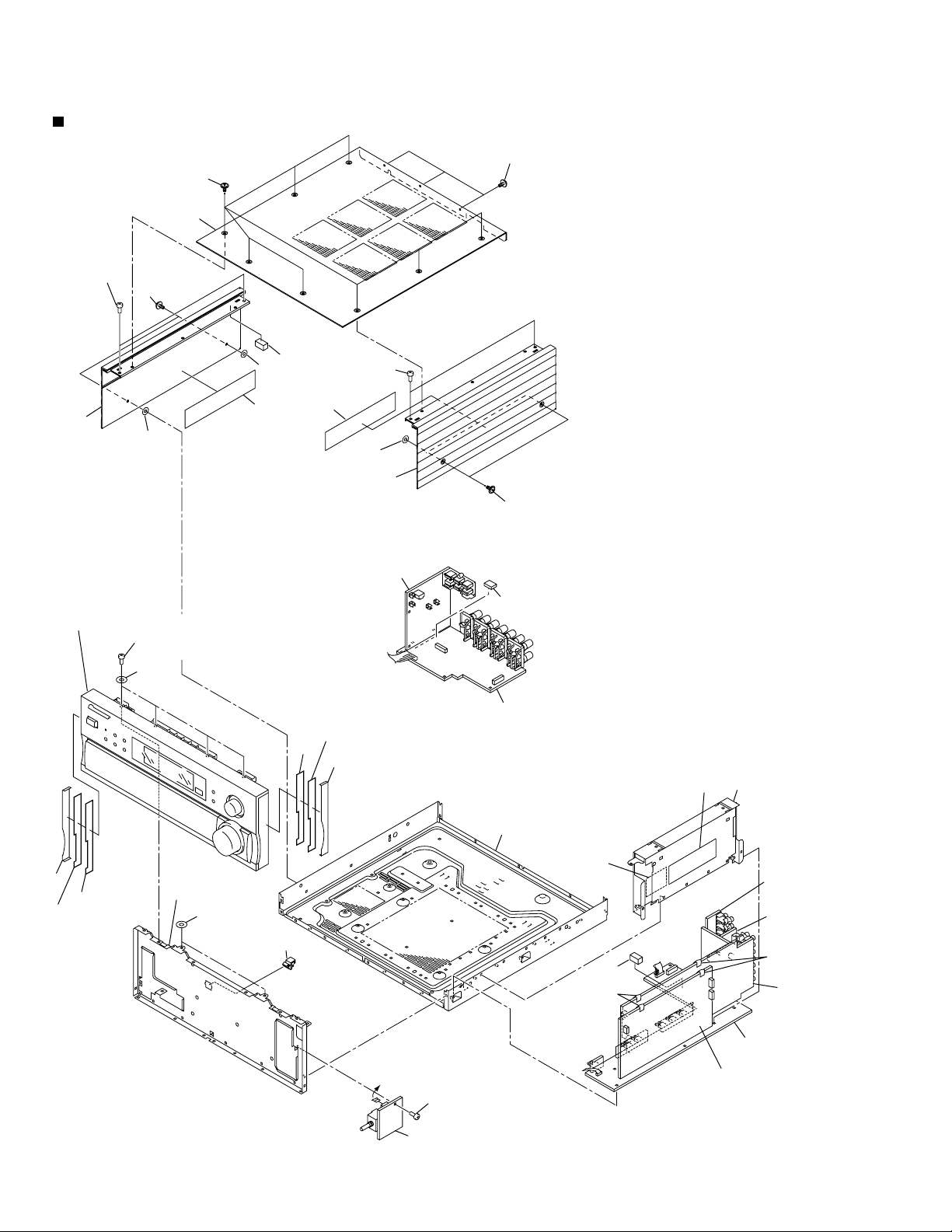
EXPLODED VIEWS
÷
EXTERIOR SECTION
18
6
17
18
Screw
BBT30P080FCC
15
8
17
2
8
FRONT PANEL SECTION
Screw
IBZ30P100FCC
19
16
16
8
PRIMARY Assy
Side Escutheon R
12
5
3
18
11
SP/PS Assy
Shield Case
9
Under Base
4
12
Side Escutheon L
4
Panel Stay
7
13
14
A-PINJACK
Assy
EXTRA-5.1
Assy
10
Remo-Con.
Cushion
C
Screw
BBZ30P080FZK
1
DSP Assy
Remo-Con.
Cushion
MAIN
CONTROL
Assy
REGULATOR
Assy
Page 5
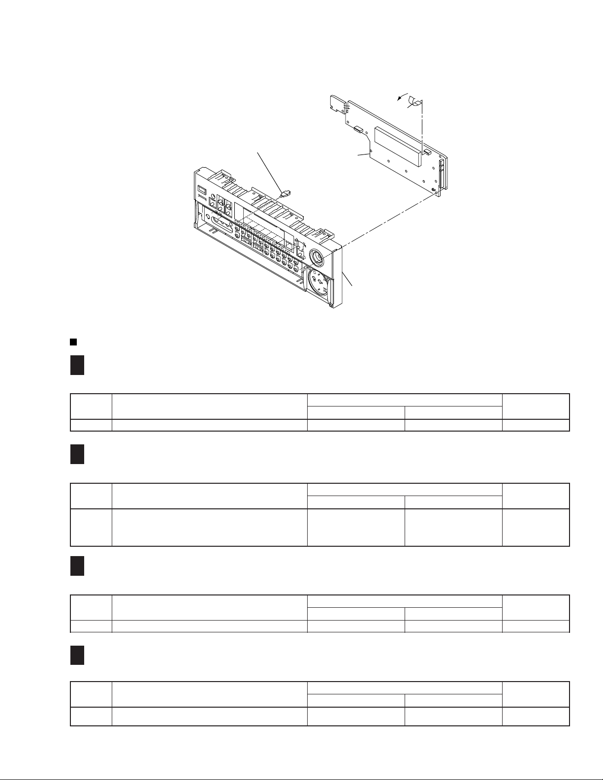
÷
FRONT PANEL SECTION
VSA-E07
C
21
20
CONTRAST OF PCB ASSEMBLIES
EXTERNAL IN (EXTRA-5.1) ASSY
A
F
AWX7348 and AWX7413 are constructed the same except for the following :
Mark Symbol and Description
JA1101–JA1103 2P PIN JACK AKB7095 AKB7121
DISPLAY Assy
Panel Base
Part No.
AWX7413 AWX7348
Remarks
A-PINJACK ASSY
B
F
AWX7346 and AWX7412 are constructed the same except for the following :
Mark Symbol and Description
JA1011–JA1013 4P PIN JACK AKB7048 AKB7108
JA1015 4P PIN JACK AKB7048 Not used
1016 2P PIN JACK AKB7210 Not used
CN1014 6P PIN JACK (For JA1015 and 1016) Not used AKB7119
CONNECTION ASSY
C
F
AWX7558 and AWX7347 are constructed the same except for the following :
Mark Symbol and Description
IC1301–IC1303 NJM4558D-D UPC4570C
V -AMP ASSY
E
F
AWX7514 and AWX7309 are constructed the same except for the following :
Mark Symbol and Description
C513, C533, C553, C613, C633 CEAT470M50 CECA470M50
C7507, C7508, C7527, C7528 Not used CEAT1R0M50
AWX7412 AWX7346
AWX7347 AWX7558
AWX7309 AWX7514
Part No.
Part No.
Part No.
Remarks
Remarks
Remarks
5
Page 6
VSA-E07
MAIN CONTROL ASSY
D
F
AWX7340 and AWX7410 are constructed the same except for the following :
Mark Symbol and Description
IC103, IC105 NJM4558MD UPC4570G2
Q991 2SC1740S Not used
Q992 2SC2412K Not used
D991 1SS355 Not used
D995 UDZ11B Not used
C109, C110 Not used CCSQCH221J50
C991 CEAT101M16 Not used
C992 CKSQYF225Z16 Not used
C995 CKSQYB103K50 Not used
R143, R144 Not used RS1/10S331J
R921 RS1/10S103J Not used
R922 Not used RS1/10S103J
R975, R976, R978, R980–R983 RS1/10S102J Not used
R991 RS1/10S471J Not used
R992 RS1/10S221J Not used
R993 RS1/10S101J Not used
R994 RS1/10S472J Not used
R996 RS1/10S0R0J Not used
CN902 13P FFC CONNECTOR 52044-1345 Not used
CN941 4P PIN JACK AKB7015 Not used
AWX7410 AWX7340
Part No.
Remarks
JA911 2P PIN JACK DKB1045 Not used
113 6P PIN JACK AKB7089 Not used
JA901, JA911 4P PIN JACK Not used AKB7075
NSP J101 Not used DB916NS0
M
F
103 6P PIN JACK (For 113) Not used AKB7088
J102 Not used DB216NS0
REGULA TOR ASSY
AWX7559 and AWX7310 are constructed the same except for the following :
Mark Symbol and Description
IC5003 NJM78M12FA Not used
D5009 D3SBA20(B) LN4SB60-4003
C5007 CEAT472M16 CEAT103M16
C5012 CKCYF103Z50 Not used
C5013 CEAT101M25 Not used
C5019, C5021, C5023 CEAT101M10 CEAT221M10
C5029 Not used CEAT221M50
C5030 (1µF/100V) Not used ACH1237
TRANS 2-2 ASSY
O
F
AWX7310 AWX7559
Part No.
AWX7470 and AWX7518 are constructed the same except for the following :
Mark Symbol and Description
IC5501 AEK7018 (4A) AEK7019 (5A)
C5501 CEANPR47M50 ACH1237 (1µF/100V)
R5501 RFA1/4PS100J RFA1/4PS220J
R5502 RD1/4PU104J Not used
AWX7518 AWX7470
Part No.
Remarks
Remarks
6
Page 7
VIDEO ASSY
P
F
AWX7419 and AWX7422 are constructed the same except for the following :
Mark Symbol and Description
702, 705 2P RCA PIN JACK AKB7017 AKB7076
706 2P RCA PIN JACK AKB7017 Not used
707 1P RCA PIN JACK AKB7020 Not used
JA701 3P PIN JACK (For 706 and 707) Not used AKB7109
S-VIDEO ASSY
Q
F
AWX7422 AWX7419
Part No.
AWX7308 and AWX7395 are constructed the same except for the following :
Mark Symbol and Description
CN801 4P MINI DIN SOCKET AKP7043 Not used
CN802, CN803 4P MINI DIN SOCKET AKP7020 AKP7023
JA801 4P MINI DIN SOCKET (For CN801) Not used AKP7049
AWX7395 AWX7308
Part No.
VSA-E07
Remarks
Remarks
DISPLAY ASSY
S
F
AWX7361 and AWX7414 are constructed the same except for the following :
Mark Symbol and Description
IC7071 Not used M66311FP
IC7401 BU1923 Not used
Q7002 DTC124EK Not used
Q7401 2SA1993 Not used
Q7402 DTC143ES Not used
Q7403 2SC1740S Not used
D7002 SLR-343VR Not used
D7071–D7079 Not used SLR-343VR(MNP)
L7401 LFA2R2J Not used
S7022, S7024–S7028, S7030 VSG1009 Not used
C7011, C7073, C7074 Not used CKSQYB102K50
C7071 Not used CEAL101M6R3
C7072 Not used CKSQYB473K50
C7401 CKSQYB472K50 Not used
C7402 CEAT2R2M50 Not used
C7091, C7403, C7404 CKSQYB102K50 Not used
C7405 CEAT101M10 Not used
C7406, C7407 CCSQCH270J50 Not used
C7408 CKSQYB561K50 Not used
C7409 CEAT1R0M50 Not used
R7038 RS1/10S271J Not used
R7047, R7048 RS1/10S223J Not used
R7071–R7079 Not used RS1/10S271J
R7080–R7083 Not used RS1/10S102J
R7092 Not used RS1/10S473J
AWX7414 AWX7361
Part No.
Remarks
R7401, S7407, S7408 RS1/10S102J Not used
R7403 RS1/10S222J Not used
R7404 RS1/10S473J Not used
R7405 RS1/10S333J Not used
R7406 RS1/10S104J Not used
CN7003 Not used 52045-0845
X7401 CRYSTAL RESONATOR (4.332MHz) ASS7004 Not used
PCB BINDER Not used VEF1040
7
Page 8
VSA-E07
ROTARY ENCODER ASSY
T
F
AWX7328 and AWX7405 are constructed the same except for the following :
Mark Symbol and Description
C7103, C7104 CKSQYB103K50 Not used
R7103, R7104 RS1/10S103J Not used
S7101 ASX7004 Not used
PRIMARY ASSY
V
F
AWX7454 and AWX7345 are constructed the same except for the following :
Mark Symbol and Description
Y6003 AWG18 BOARD IN ADX7321 Not used
Y6004 AWG18 BOARD IN ADX7320 Not used
Y6005 AWG18 BOARD IN ADX7319 Not used
DIGITAL I/O ASSY
W
F
AWX7405 AWX7328
AWX7345 AWX7454
Part No.
Part No.
Remarks
Remarks
AWX7315 and AWX7396 are constructed the same except for the following :
Mark Symbol and Description
JA1204 2P PIN JACK AKB7095 AKB7121
PCB PARTS LIST
Mark No. Description Part No.
VOLUME ASSY
Z
F
SEMICONDUCTORS
Q7301, Q7302 2SA1993
Q7303, Q7304 2SC5395
D7301 1SR154-400
CAPACITORS
C7301 CEANP100M16
C7302 CEAT220M50
C7303 CEAT471M6R3
RESISTORS
VR7301 (VARIABLE WITH MOTOR) ACX7037
Other Resistors RS1/10S J
AWX7396 AWX7315
Part No.
Remarks
OTHERS
CN7301 8P FFC CONNECTOR 52045-0845
KN7301 EARTH METAL FITTING VNF1084
8
Page 9

1
234
2. PCB CONNECTION DIAGRAM
VSA-E07
2.1 VOLUME ASSY
VOLUME ASSY
Z
F
Q7304Q7301
Q7503
Q7502
VR7301
VOLUME ASSY
Z
F
S
CN7003
(ANP7010-C) (ANP7010-C)
SIDE A SIDE B
A
B
C
D
F
9
Z
1
2
3
4
Page 10

1
VSA-E07
3. SCHEMATIC DIAGRAM
3.1 MAIN CONTROL ASSY (1/3)
: The power supply is shown
A
B
with the marked box.
CN906
52045-0545
F
S
CN7005
23
2/3
D
D
2/3
4
TV
1SS355
1SS355
LD
P
TU
T2
CD
T2
TU
TU
T2
T2
JA901 (1/2)JA901 (2/2)
CD
JA911 (1/2)JA911 (2/2)
C
TU
DB916NS0
CD
MD
V2
V1
JA901 : AKB7075
JA911 : AKB7075
D
CN101
10
D
1/3F
1234
DB216NS0
P
V1
TV
V2
LD
MD
C
CN1353
Page 11

5
678
VSA-E07
Note : When ordering service parts, be sure to refer to "EXPLODED VIEWS and PARTS LIST" or "PCB PARTS LIST"
: AUDIO SIGNAL ROUTE
D
1/3 F
MAIN CONTROL ASSY
(AWX7340)
LD
: AUDIO SIGNAL ROUTE (LD)
TV
: AUDIO SIGNAL ROUTE (TV)
V1
: AUDIO SIGNAL ROUTE (VCR1)
V2
: AUDIO SIGNAL ROUTE (VCR2)
MD
: AUDIO SIGNAL ROUTE (MD)
P
: AUDIO SIGNAL ROUTE (PHONO)
TU
: AUDIO SIGNAL ROUTE (TUNER)
CD
: AUDIO SIGNAL ROUTE (CD)
T2
: AUDIO SIGNAL ROUTE (TAPE2)
A
B
UPC4570G2
UPC4570G2
UPC4570G2
1/2
C
2/2
UPC4570G2
D
CN104
F
M
CN5004 CN1302
5
6
7
C
D
1/3F
CN103
11
8
Page 12

1
VSA-E07
3.2 MAIN CONTROL ASSY (3/3)
A
B
23
CN9551
4/5
Y
CN903
4
D905-D908
1SS355
C
2/3
D
D901-D904
1SS355
1SS355
D
12
D
3/3F
1234
CN901
M
CN920
F
M
F
CN5008CN5005
Page 13

5
D
3/3 F
MAIN CONTROL ASSY
(AWX7340)
678
VSA-E07
: The power supply is shown with the marked box.
F
S
CN7001
A
CN904
B
CN108
5
M
F
CN5003
C
CN905
D
P
CN701
D
3/3F
6
7
8
13
Page 14

1
VSA-E07
3.3 V-AMP ASSY (1/2)
23
4
A
B
E
1/2 F
V-AMP ASSY
(AWX7514)
CN501
E
2/2
IC7601 (1/2)
UPC4570G2
IC7501 (1/2)
UPC4570G2
IC7541 (1/2)
UPC4570G2
2/3
D
CN105
C
2/2
E
505, 506
VEF1040
D
IC7521 (1/2)
UPC4570G2
IC7621 (1/2)
UPC4570G2
14
E
1/2F
1234
Page 15

5
678
VSA-E07
IC7601 (2/2)
UPC4570G2
IC7501 (2/2)
UPC4570G2
: AUDIO SIGNAL ROUTE
A
B
IC7541 (2/2)
UPC4570G2
IC7521 (2/2)
UPC4570G2
IC7621 (2/2)
UPC4570G2
E
2/2
C
D
E
5
6
7
1/2F
8
15
Page 16

1
23
VSA-E07
3.4 REGULATOR, TRANS 1 and TRANS 2-2 ASSYS
M
F
REGULATOR ASSY (AWX7559)
A
CN5001
52147-0810
L
3004
CN5002
4
B
D5010
1SS133
CN3003
L
MTZJ10CMTZJ5.1B
C
TRANS 1 ASSY
N
(AWX7316)
C5502
ACH1237
C5501
ACH1237
NP 1/100
NP 1/100
C5501
5501
C5030
ACH1237
NP 1/100
LN4SB60-4003
V
R5501
5009
R5501
22
O
F
D
J
16
M
NFO
F
1234
TRANS 2-2 ASSY
(AWX7470)
POWER TRANSFORMER
CAUTION : FOR CONTINUED PROTECTION AGAINST RISK OF FIRE.
REPLACE ONLY WITH SAME TYPE NO. 491.200 MFD, BY
LITTELFUSE INC. FOR IC5009, IC5010 (AEK7023).
CAUTION : FOR CONTINUED PROTECTION AGAINST RISK OF FIRE.
REPLACE ONLY WITH SAME TYPE NO. 491005 MFD, BY
LITTELFUSE INC. FOR IC5501 (AEK7019).
Page 17

5
678
VSA-E07
: AUDIO SIGNAL ROUTE
CN5003
CN5004
3/3 F
D
CN108
A
CN5008
1/3 F
D
CN104
3/3 F
D
CN920
3/3 F
D
CN901
B
C
CN5006 CN5007
CN9801
2/5
CN9802
2/5
Y
5
6
Y
7
CN5005
M
8
F
D
17
Page 18

1
23
4
VSA-E07
3.5 H. PHONE/F. VIDEO, DISPLAY, ROTARY ENCODER and VOLUME ASSYS
H. PHONE/F. VIDEO ASSY
R
A
B
(AWX7342)
CN7201 CN7004
DISPLAY ASSY
S
F
(AWX7361)
S7001 : STANDARD
S7002 : STEREO
C
S7003 : DSP MODE
S7004 : ADVANCED
S7005 : THX CINEMA
S7006 : STAND BY/ON
S7007 : EXTERNAL
S7008 : SPEAKERS
S7009 : DIRECT
S7010 : BASS –
S7011 : LOUDNESS
S7012 : BASS +
S7013 : MIDNIGHT
S7014 : TREBLE –
S7015 : DIGITAL NR
S7016 : TREBLE +
S7017 : SIGNAL SELECT
S7018 : INPUT ATT
S7019 : MPX
S7020 : TAPE2 MONITOR
S7021 : LEVEL –
S7023 : LEVEL +
S7029 : FL DIMMER
D
18
DECODER IN
M663111FP
R
S
F
1234
CN7005
1/3 F
D
CN906
Page 19

5
678
VSA-E07
A
ROTARY ENCODER ASSY
T
F
(AWX7328)
CN7002 CN7101
B
CN7003 CN7301
Z
F
VOLUME ASSY (AWX7367)
2SA1037K
C
CN7001
D
CN904
3/3 F
D
F
T
S
5
6
7
F
Z
8
F
19
Page 20

VSA-E07
4. REMOTE CONTROL UNIT [AXD7217(CU-VSA032)]
4.1 EXPLODED VIEWS AND PARTS LIST
NOTES:• Parts marked by "NSP" are generally unavailable because they are not in our Master Spare Parts List.
The mark found on some component parts indicates the importance of the safety factor of the part.
•
Therefore, when replacing, be sure to use parts of identical designation.
Screws adjacent to mark on the product are used for disassembly.
•
15
37
39
29
19
17
33
16
18
19
18
1
38
32
31
36
29
29
13
34
12
2
10
14
11
9
8
7
20
20
21
29
24
27
35
22
26
29
29
23
22
6
5
30
25
Page 21

PARTS LIST
•
Mark No. Description Part No.
1 PWB Assy RRC4–7251–01
2 PCB Assy AZC7296
3 • • • • •
4 • • • • •
5 Terminal A 411RRC15801R
6 Terminal B 411RRC15901R
7 Jumper Cable E–AA1446–001
8 EL Module AZC7294
9 LCD Module AZC7295
10 Touch Panel NTX01005701R
11 Frame 501RRC01901R
12 LCD Holder AZN7787
13 Seal A AZA7369
14 Seal B AZA7370
15 Upper Case Assy RRC4–7251–02
16 Case A AZN7795
17 Name Plate AZA7375
18 Cushion A 701RRC04801R
19 Cushion B 701RRC04901R
20 Bottom Case Assy RRC4–7251–03
VSA-E07
21 Case B AZN7796
22 Filter AZA7343
23 Pen Holder AZN7798
24 Terminal 413RRC11201R
25 Battery Cover Assy RRC4–7251–04
26 Battery Cover AZN7797
27 Cushion C 701RRC03501R
28 • • • • •
29 Screw AZB7144
30 Touch Pen AZA7350
31 Slide Switch JSB1220–0111
32 Slide Knob AZA7365
33 FPC Connector CFP5519–0101
34 FPC Connector E-CP0535–008
35 MT Switch JPM1030–0801
36 Key Top A AZA7363
37 Key Top B AZA7364
38 Rubber Sheet A AZA7348
39 Rubber Sheet B AZA7371
21
Page 22

1
VSA-E07
4.2 SCHEMATIC DIAGRAM
23
4
A
R20
100k
P63
P65
P64
Q17
DTA114YKA
Q13
2SC2712
P107
P103
P102
R22
100k
Q9
DTA114YKA
Q11
2SK2009
B
3.3
R19
R18
100k
100k
18 17 16 15 14 13
12 11 10 9 8 7
C
6 5 4 3 2 1
SUB PWB
MODEL SWITCH FLASH MODE SWITCH
JP1
MODEL
JP2
J (JAPAN)
H
H
KU (NORTH AMERICA)
L
L
HY (EUROPE)
H
H
D
TABLET
XRX+YRY-XGX-YG
2 3 4 5 6 7 81
Q12
DTC114YKA
28
X+
29
X-
30
Y+
31
Y-
32
NC
33
RTS
34
TXD
35
DTA
36
PS
R23
47k
P101
P100
MODE
NORMAL
WRITING
BAT
Y+
CN1
26
27
NC
ST0
ST1
SW2
SW1
SW0
GND
ST4
IC3
Z-V0660-02419
DC025CTS24NC23GND22ST321ST220RXO
PA
123456789
C7
100p
P60
P61
P
62
P97
P96
P106
P105
P104
JP3
JP4 JP5
EXIST
NONE NONE
EXIST EXISTNONE
6.8
2
1
2 IC7
3.6V
3
C6
47/10
19
18
YG
AGND
17
YR
16
XG
15
XR
14
NC
13
VREF
12
RST
11
VDD
10
XO
R24 1M
R25
X2
5.6k
C8
0.015
K1 :
K2 : FUNCTION
K6 : VOL K7 : FUNCTION
K12 : CH +
K13 : CH K18 : VOL +
JP6
H
L
R43
1k
P90
P72
P81
1
IC6
3.3V
3
3.3
C10 - C13
C10
C9
0.1
C3
0.1
6.8
R27
82
Q1
2SC1712
INT2
R2
1k
1000p
C11 C12 C13
R26
130k
P86
R9
82
R10
10k
P92
3
4
C2
0.1F
5
D6 - D9
ISS226
R27 1k
R28 1k
R29 1k
R30 1k
R11
7.5
IR1
SID303C
Q2
2SC3265
Q7
FM02
D12
D13
D14
74
D11
D1273D1372D1471D15
P93
P92
P94
234
P93
P92
IC5
IS489
C18
47
/10
P91
D15
P90
5
P90
D11
75
D10
D9
D8
D7
D6
3.3
IR3
SID303C
Q3
2SC3265
23IC9
2.0V
R18
7.5
D5
D4
D3
D2
D1
D0
D7
IR2
SID303C
R14
82
R13
82
R12
10k
3.33.3
R47
1k
D8 D9
Q15
DTC114YKA
R17
100k
R15
7.5
R52
1k
RESET
SW
D6
Q14
2SC3265
3.3
1
2
P107
P106
P105
P104
P103
P102
P101
P100
P97
P96
3.3
P73
1
R31
1k
76
77
78
79
80
81
82
83
84
85
86
87
88
89
90
91
92
93
94
95
96
97
98
99
100
SW1
3.3
C11
0.01
Q4
2SC3265
D4
1SS294
C4
D10
D9
D8
D7
D6
D5
D4
D3
D2
D1
D0
P107
P106
P105
P104
P103
P102
P101
AVSS
P100
VREF
AVCC
P97
P96
P95
3.3
RESET
P67
1
1
2
3
22
1234
Page 23

5
678
VSA-E07
Note : When ordering service parts, be sure to refer to "EXPLODED VIEWS and P AR TS LIST" or "PCB PARTS LIST".
A0A1A2A3A4A5A6
70A069A168A267A366A465A564A663
A7
62
A7
VSS
IC1
M30612MCA-228GP
BYTE
CNVSS
P87
P86
RESET
XOUT
VSS
XIN
678
R51
C6
0.1
P87
9
P86
R3
0
VCC
101112131415161718192021222324
RESET
X1 4MHz
3.3
3.3
EL
MODULE
VDD
HON
GND
CL705T-1
A8
61
A8
NMI
C16
60
VCC
INT2
R47
0.1
A9
59A958
1k
INT2
A10
INT1
A11
A12
A13
A14
A15
A16
A1057A1156A1255A1354A1453A1552A16
ALE/P56
INT0
P81
P80
P77
P76
P75
P74
P81
30
Q6
2SJ356
R6
10k
R4
1k
R5
1k
A1725
51
A17
A18
A19
CS0
CS1
CS2
CS3
WRL
WRH
RD
BCLK
P54
P55
RDY
P60
P61
P62
P63
P64
P65
P66
P67
P70
P71
P72
P73
JP1
P73
SB330A30FS
1
VOIN
2
VCLK
3
VSTRB
4
VOUT
6.8
Q8
2SC2712
50
49
48
47
46
45
44
43
42
41
40
39
38
37
36
P60
35
P61
34
P62
33
P63
32
P64
31
P65
30
29
28
27
26
3.3
(H)
(L)
IC4
ON/OFF
CONT
C6
47
/50
D3 1SS294
BZ
BCLK
VSS
VIN
A18
CS0
CS1
CS2
CS3
WRL
WRH
RD
JP3
P72
P67
8
7
6
5
3.3
C25
47/10
JP4
2SK7119
Q5
JP2
JP5
R7
1k
L1
47µH
6.8
R8
1k
C24
0.1
3.3
3.3
3.3
3.3
(H)
(L)
(H)
(L)
1
2
JP6
CP
LP
FLM
VD0
VD1
VD2
VD3
IC16
R32
6.8k
R33
6.8k
R34
6.8k
R35
6.8k
R36
6.8k
4
3.3
30
10
12
13
IC10 BA1652AF
65
VSS
66
CP
67
LP
68
FLM
69
VD0
70
VD1
71
VD2
72
VD3
73
VD4
74
VD5
75
VD6
76
VD7
77
VDD
78
N.C.
79
N.C.
80
VSS
1
2
3
2
5
6
9
IC18
41
2
R37
47
R38
4
47
1
R39
47
7
R40
47
8
R41
47
14
11
D15
D14
D13
D12
64
63
62M61
60
59
D15
VDD
IOCS
ICS
RWR
LCDENB
RWR
LWRRDMCS
LWRRDMCS
D1458D1357D1256D1155D10
WAIT
RDY
VSS
VSS
123456789
1
2 3 4 5 6 7 8 9
IC15
4
(1/2)
PR
Q
D
CLK
Q
CLA
1
10
PR
Q
D
CLK
Q
CLA
13
C19
2.2/50
C20
2.7/50
C22
2,2/50
C23
2.2
/50
D7D6D5D4D3D2D1
52
51
50D749D648D547D446
VSS
VDD
5
6
9
8
IC15
(2/2)
V2
V3
CP
VD3
VD2
VD1
VD0
LP
M
V5
V0
V1
V4
FLM
45
D3
D2
2
3
412
11
C21
3.3/50
R42
15
D9
D8
D11
D10
54D953
D8
IC2
M66272FP
VDD
MPUCLK
VSS
RESET
MPUSEL
VSS
BHEA0A1A2A3A4A5A6A7
101112131415161718192021222324
RST
A0A1A2A3A4A5A6
RCLK
44D143
3.3
P93
D0
42
D0
VDD
SWAP
A7
VDD
VSS
N.C.
N.C.
N.C.
CSE
VSS
A14
A13
A12
A11
A10
VSS
VDD
A9
A8
10
41
CN2
10
11
12
13
14
15
16
17
18
19
VSS
VSS
1
2
3
4
5
6
7
8
9
CN4
40
39
38
37
36
35
34
33
32
31
30
29
28
27
26
25
3.3
LCD MODULE
A14
A13
A12
A11
A10
A9
A8
A
B
C
D
23
5
6
7
8
Page 24

1
VSA-E07
4.3 PCB DIAGRAM
A
R3
C5
C26
B
C
7
D
C21
R42
R18
R13
R20
1
C19
CN3
C4
1
C22
1
3
CN1
IC9
3
RESET
81
CN2
19
C23
C20
R8
23
JP2
(H)
76
100
C18
C17
R7
R21
R33
4M
Q4
Q2
R34
X1
Q5
Q1
R43
R12
R10
Q14
R17
R41
Q3
R35
1
R9
JP5(H)
R31
D5
L
R13
R36
IC1
M30622
R49
R6
D3
C25
5
SB330A30FS
IR3
IR1
IR2
R4
51
C16
JP1
Q6
31
IC5
C6
Q8
Q10
Q9
Q12
Q11
D4
D2
T1
C24
R52
R47
IC8
R37
R38
R39
R40
R41
JP
C2
JP3
BAT
R45
10
CN4
1
BA10324AF
71
8
64
IC2
1
M6627AFP
IC6
3
7
8
R44
R46
C9
C3
10 18
Z-Y0660
-02419
R30
I31
IC3
IC10
14
23
C8
1M
IC7
R26
19
24
IR2
Q7
5
1
R25
C7
3
R24
40
25
D6
D7
D8
D9
T2
X2
1
C10
C11
C12
C13
R27
R28
R29
BZ
JP2
(L)
JP5
(L)
R22
R23
27
1
Q15
Q13
28
BAT
IC15
7474
R51
R32
25
R5
IC16
1
IC4
8
R11
4
G
V
C
50
IC6 IC7
SW1
Q7
IC1
26
IC9 IC8
IC15
R50
IC16
1
IC17
IC17
1
IC18
Q6
IC5 IC18
Q13
L1
IC4
IC3
JP6
Q5
Q1
Q10
Q4
R16
R15
Q9
Q12
Q11
Q2
Q14
Q3
IC10
C1
IC2
Q8
24
SIDE A
1234
Page 25

1
234
VSA-E07
A
K1
K2
K12
K13
K18
1
IC13
114 14
IC14
K6
K7
28
LC35256CM
15
28
LC35256CM
15
EL
HON
GND
VDD
B
C
D
SIDE B
1
2
3
4
25
 Loading...