

Page 1

AUDIO/VIDEO
MULTI-CHANNEL AMPLIFIER
VSA-E07
Operating Instructions
Page 2
IMPORTANT 1
The lightning flash with arrowhead symbol, within an
equilateral triangle, is intended to alert the user to the
presence of uninsulated "dangerous voltage" within the
product's enclosure that may be of sufficient magnitude
to constitute a risk of electric shock to persons.
CAUTION
RISK OF ELECTRIC SHOCK
DO NOT OPEN
CAUTION:
TO PREVENT THE RISK OF ELECTRIC SHOCK, DO
NOT REMOVE COVER (OR BACK). NO USERSERVICEABLE PARTS INSIDE. REFER SERVICING TO
QUALIFIED SERVICE PERSONNEL.
The exclamation point within an equilateral triangle is
intended to alert the user to the presence of important
operating and maintenance (servicing) instructions in
the literature accompanying the appliance.
The cut-off plug should be disposed of and must not be
IMPORTANT 2
FOR USE IN THE UNITED
KINGDOM
The wires in this mains lead are coloured in
accordance with the following code :
Blue : Neutral
Brown : Live
If the plug provided is unsuitable for your socket
outlets, the plug must be cut off and a suitable plug
fitted.
inserted into any 13 amp socket as this can result in electric
shock. The plug or adaptor or the distribution panel should
be provided with 5 amp fuse. As the colours of the wires in
the mains lead of this appliance may not correspond with
coloured markings identifying the terminals in your plug,
proceed as follows :
The wire which is coloured blue must be connected to the
terminal which is marked with the letter N or coloured black.
The wire which is coloured brown must be connected
to the terminal which is marked with the letter L or coloured
red.
Thank you for buying this Pioneer product.
Please read through these operating instructions
so you will know how to operate your model properly. After you have finished reading the instructions, put them away in a safe place for future reference.
In some countries or regions, the shape of the
power plug and power outlet may sometimes differ from that shown in the explanatory drawings.
However, the method of connecting and operating the unit is the same.
Power cord CAUTION!
Handle the power cord by the plug. Do not pull
out the plug by tugging the cord and never
touch the power cord when your hands are
wet as this could cause a short circuit or
electric shock. Do not place the unit, a piece of
furniture, etc., on the power cord, or pinch the
cord. Never make a knot in the cord or tie it
with other cords. The power cords should be
routed such that they are not likely to be
stepped on. A damaged power cord can cause
a fire or give you an electrical shock. Check the
power cord once in a while. When you find it
damaged, ask your nearest PIONEER authorized service center or your dealer for a replacement.
Do not connect either wire to the earth terminal of a
three - pin plug.
NOTE
After replacing or changing a fuse, the fuse cover in the
plug must be replaced with a fuse cover which corresponds to the colour of the insert in the base of the plug
or the word that is embossed on the base of the plug, and
the appliance must not be used without a fuse cover. If
lost replacement fuse covers can be obtained from:
your dealer.
Only 5 A fuses approved by B.S.I. or A.S.T.A. to B.S.
1362 should be used.
[For European model]
If the socket outlets on the associated equipment
are not suitable for the plug supplied with the
product the plug must be removed and
appropriate one fitted.
The cut-off plug must be disposed of as an
electrical shock hazard could exist if connected to
a socket outlet.
WARNING: TO PREVENT FIRE OR SHOCK HAZARD,
DO NOT EXPOSE THIS APPLIANCE TO RAIN OR
MOISTURE.
This product complies with the Low Voltage Directive
(73/23/EEC), EMC Directives (89/336/EEC, 92/31/EEC)
and CE Marking Directive (93/68/EEC).
THE POWER SWITCH IS SECONDARY CONNECTED
AND THEREFORE DOES NOT SEPARATE THE UNIT
FROM MAINS POWER IN STANDBY POSITION.
Maintenance of External Surfaces
• Use a polishing cloth or dry cloth to wipe off dust and dirt.
• When the surfaces are dirty, wipe with a soft cloth dipped in some neutral cleanser diluted five or six times
with water, and wrung out well, and then wipe again with a dry cloth. Do not use furniture wax or cleansers.
• Never use thinners, benzine, insecticide sprays or other chemicals on or near this unit, since these will corrode
the surfaces.
2
En
Page 3

Table of Contents
Before You Start .................................................................................................. 5
Checking the Supplied Accessories ................................................................ 5
How to Use This Manual.................................................................................. 5
Installing the Amplifier......................................................................................5
Opening the Front Panel .................................................................................. 6
Preparing the Remote Control......................................................................... 6
Connecting Your Equipment .............................................................................. 8
Audio Components .......................................................................................... 8
Video Components ........................................................................................... 9
Digital Connections .........................................................................................10
External Decoder Input .................................................................................. 12
Speakers ...........................................................................................................13
Connecting Additional Amplifiers ................................................................. 15
Power Connections (AC OUTLETS) (Except for the UK model.)................. 15
Displays and Controls....................................................................................... 16
Front Panel .......................................................................................................16
Display ..............................................................................................................18
Remote Control............................................................................................... 20
Basic Amplifier LCD Screens ......................................................................... 21
Initial Set Up...................................................................................................... 23
On Screen Display .......................................................................................... 23
Setting Up the Remote Control ..................................................................... 24
Setting Up for Surround Sound .................................................................... 26
PREPARATION
UP
SET
Basic Playback ................................................................................................... 38
Playing Source with Stereo Sound ................................................................38
Sound Modes...................................................................................................40
Selecting a Sound Mode.................................................................................42
Playing Source with Dolby Digital, DTS Sound or MPEG Audio.................43
Using MPEG audio discs .............................................................................44
Switching ANALOG/DIGITAL signal input .................................................45
Reducing noise during playback (DIGITAL NR function) ......................... 46
96kHz/24bit Performance.............................................................................46
Listening in MIDNIGHT listening mode .................................................... 47
External decoder playback ......................................................................... 47
Listening in LOUDNESS mode ...................................................................48
Adjusting bass and treble (tone control) ...................................................48
Direct playback .............................................................................................49
Adjusting the brightness of the display (front panel only)...................... 49
Remote Control of Other Components...........................................................50
Setting Up the Remote Control to Control Other Components...................50
Locking the Settings ........................................................................................54
Using Remote Control with Other Components ...........................................55
Using Other Functions...................................................................................... 62
Recording from Audio Components ..............................................................62
Recording from Video Components ..............................................................62
Multi Operations ..............................................................................................63
System OFF ......................................................................................................65
Setting Up the Direct Function .......................................................................67
Resetting the Remote Control ........................................................................67
Techno Tidbits and Problem-solving...............................................................68
Dolby Digital ................................................................................................... 68
DTS ...................................................................................................................69
MPEG Audio.....................................................................................................70
THX ...................................................................................................................70
Preset Code List .............................................................................................. 71
Troubleshooting.............................................................................................. 74
Specifications.................................................................................... Back cover
En
OPERATION
3
Page 4
Features
MPEG (Moving Picture Experts
Group) decoder equipped
DVD and other media recorded in MPEG audio can
be played back.
The MPEG logo is a registered trademark of
Royal Philips Electronics.
Automatic Decoding of DTS
(Digital Theater Systems)
This is the latest and most widely used digital theater
system for cinemas throughout the world. The
decoder has been incorporated into this amplifier and
is able to achieve high sound quality as well as
produce dynamic surround sound effects.
“DTS” and “DTS Digital Surround” are
trademarks of Digital Theater Systems, Inc.
Manufactured under licence from Digital Theater
Systems, Inc.
R
Automatic Decoding of Dolby
Digital and Dolby Pro Logic
No need to worry about program formats. When
playing Dolby Digital or Dolby Surround software in
2 (Dolby) Surround mode, decoding switches
the
automatically according to the input signal.
Manufactured under license from Dolby
Laboratories. “Dolby”, “AC-3”, “Pro Logic”,
and double-D symbol are trademarks of Dolby
Laboratories. Confidential Unpublished Works.
©
1992 - 1997 Dolby Laboratories. All rights
reserved.
Direct Energy MOS amplifier
The VSA-E07 amplifier incorporates 5 independent
130 watt built in power amplifiers, with highperformance Hex power MOS FET output
transistors. This construction provides improved
linearity and accurate reproduction of each channel
for true high fidelity reproduction from even the most
demanding Dolby Digital and DTS program sources.
True Home Cinema with THX®
Certification
The HOME THX CINEMA surround mode employs
special processing to allow you to enjoy movie
soundtracks with the same level of power and
realism you experience in well designed movie
theaters. You can enjoy this effect with both Dolby
Digital, Dolby Surround and DTS sources.
Manufactured under license from Lucasfilm Ltd.
Lucasfilm and THX are trademarks of Lucasfilm
Ltd.
Advanced Theater Modes
This mode enhances the sound of either film or
music so a more dramatic effect can be achieved.
The four modes are each designed to accentuate
specific sound qualities, giving the listener a wide
range of possibilities.
DSP Surround Modes
DSP (Digital Signal Processing) surround mode gives
you the capability of transforming your living room
into six different sonic environments when listening
to music.
Midnight Listening Mode
Midnight Listening mode allows you to obtain
excellent surround sound effects even when
listening at low volumes, something that was
previously impossible.
Digital Noise Reduction
Digital Noise reduction is the latest technology for
filtering out unwanted noise. It produces clear,
resonant tones.
New LCD Remote Control
This touch sensitive screen remote control is the
latest in convenient technology. It's easily viewed
screen can access a huge amount of different
buttons. Instead of the old method where one button
had to perform many tasks, this remote can instantly
change screens, allowing one button to have just
one, clearly marked purpose. This remote can be
used to operate a variety of other components
simply by recalling the appropriate setup codes or by
using the learning function to teach the remote
control new commands. In addition, the multioperation functions allow you to perform a variety of
operations automatically.
4
En
The Energy-saving Design
This unit is designed to use minimal electricity when
power is switched OFF (in Standby mode).
Regarding the power consumption in standby mode,
refer to "Specifications" on back cover.
Page 5
Before You Start
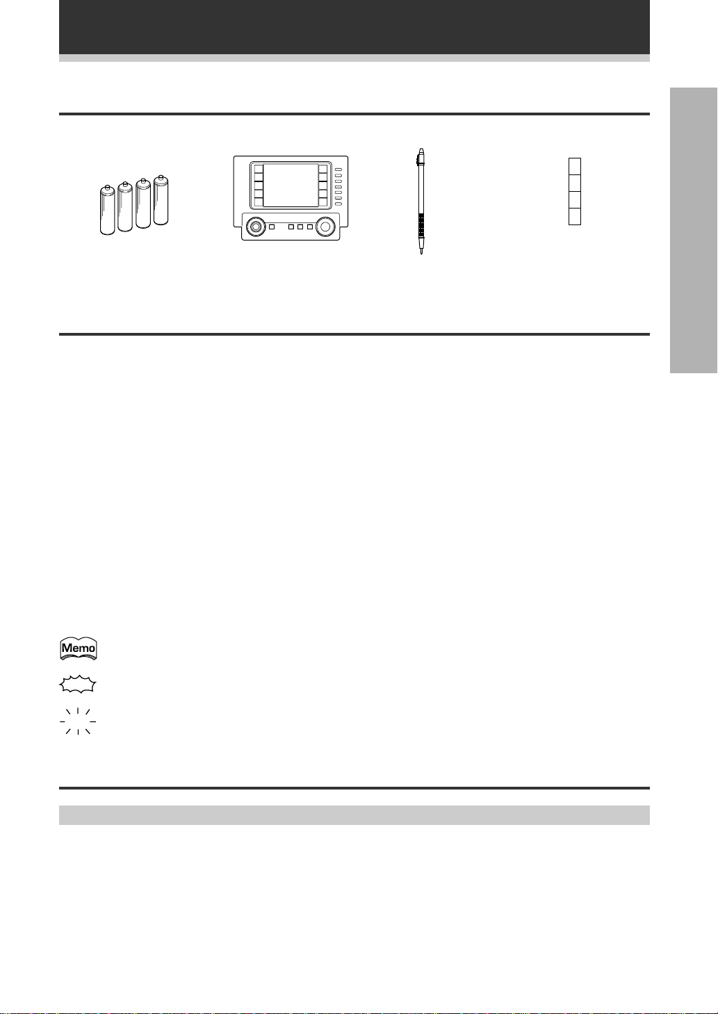
Checking the Supplied Accessories
Please check that you have received all of the following supplied accessories.
PREPARATION
(Attached to the back
of the remote control)
Cushion for Remote × 4 "AA" IEC LR6 batteries × 4 Remote control unit Touch pen
How to Use This Manual
This manual is for the VSA-E07 Audio/Video Multi-Channel Amplifier.
This manual is divided into two main sections which will tell you how to setup and use the unit :
PREPARATION
First carry out the tasks below in this "Before You Start" section to prepare the remote control, then connect the
amplifier to your other components as described in "Connecting Your Equipment" (p.8). Take special care to
connect your digital equipment like DVD and LD player properly to be able to take advantage of the amplifier’s
surround sound systems (p.10-11). To learn about a specific button, control, or indicator, see "Displays &
Controls" starting on p.16.
SETUP
Performing the tasks in "Initial Set Up" (from p.23) is essential to get proper surround sound.
OPERATION
To play some music or soundtrack refer to "Basic Playback" on p.38. Doing the operations in "Remote Control of
Other Components" (p.50) is highly recommended so you can use this unit's remote control for all your
components. "Using Other Functions" (p.62) explains the other possibilities of the amplifier.
"Techno Tidbits & Problem-solving" (p.68) provide detailed technical information and a troubleshooting guide.
The following marks and symbols are used throughout the manual:
Provides additional information, precautions, and advice.
Indicates a blinking button, indicator, or display.
Indicates a steadily lit button, indicator, or display.
Installing the Amplifier
Ventilation
• When installing this unit, make sure to leave space around the unit for ventilation to improve heat radiation (at
least 60 cm at the top, 10 cm at the rear, and 30 cm at each side). If not enough space is provided between
the unit and walls or other equipment, heat will build up inside, interfering with performance or causing
malfunctions.
• Do not place on a thick carpet, bed, sofa or fabric having a thick pile. Do not cover with fabric or other
covering.
Anything that blocks ventilation will cause the internal temperature to rise, which may lead to breakdown or
fire hazard.
5
En
Page 6
Before You Start
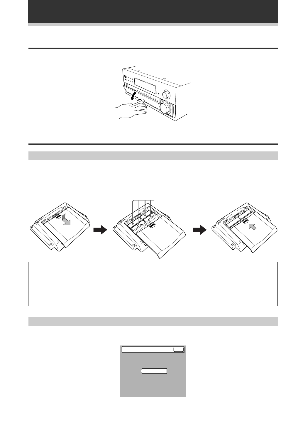
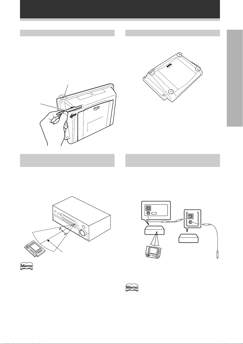
Opening the Front Panel
To open the front panel push gently on the lower third of the panel with your finger.
Preparing the Remote Control
Loading the batteries
Load the batteries into the remote control as shown below. The remote control uses a lot of power due to the
LCD display so please use alkaline batteries. Depending on individual use you may have to change the batteries
fairly often but most users should be able to get an average of 1-3 months of battery life. When you notice a
decrease in the operating range (see next page) or if the alarm sounds, replace all batteries with new ones.
NOTE: After replacing the batteries, the touch panel will need re-adjusting (see p.24).
12 3
(
9
(
AA dry cell batteries
((“AA”IEC LR6)×4)
(
9
9
(
9
CAUTION!
Incorrect use of batteries may result in such hazards as leakage and bursting. Observe the following
precautions.
• Never use new and old batteries together.
• Insert the plus and minus sides of the batteries properly according to the marks in the battery case.
• Batteries with the same shape may have different voltages. Do not use different batteries together.
Remote Control Battery Alarm
When the batteries get too weak to operate the remote control properly an alarm will sound and a warning
screen will appear on the remote. Change the batteries as above.
Change Battery !!
SIZE AA, LR6SIZE AA, LR6
OK ?
6
En
Page 7
Before You Start
The Touch Pen & Backlight
The touch pen is located in the back right-hand
corner of the remote control. Take it out by sliding
your finger along the bottom right edge of the
remote control and then grasping the pen with
thumb and forefinger.
The backlight button is located in the top right-hand
corner on the back of the remote control. Use this
button in low-lighting to see the screen more clearly.
Back light switch
Touch pen
Operating range of remote
control unit
Remote Control Cushions
Apply the cushions to the feet of the remote control
as shown in the diagram below.
PREPARATION
Operating other PIONEER
components
The area in which you can use the remote control to
operate the VSA-E07 is fairly large. To use, point the
remote control toward the remote sensor on the
front panel of this unit while within the range shown
below.
30
30
7m
Remote control may not function properly if:
• There are obstacles between the remote
control and the remote sensor.
• Direct sunlight or fluorescent light is
shining onto the remote sensor.
• The receiver located near a device
emitting infrared rays.
• Operated simultaneously with another
remote control which uses infrared rays.
Connecting an optional control cord allows you to
operate other PIONEER components simply by
pointing the amplifier’s remote control at the remote
sensor on the front panel of the amplifier. The
amplifier then sends the remote control signals to
the other devices via the CONTROL OUT terminal.
IN
Amplifier
Remote Control
You can also control PIONEER components
(and those made by other manufactures) by
pointing the amplifier’s remote control
directly at the respective component. This
type of operation does not require control
cords. All you have to do is recall the
appropriate preset code (Refer to"Recalling
setting stored in the remote control" on
page 50)).
OUT
CONTROL
PIONEER component
bearing the Î mark.
CONTROL
IN
OUT
To CONTROL IN
terminal of another
PIONEER component
bearing the Î mark.
En
7
Page 8
Connecting Your Equipment
Before making or changing the connections, switch off the power switch and disconnect the power cord
from the AC outlet.
• To cover all possible Laser Discs, a DVD/LD player or LD player requires an analog connection and two digital
connections (p.11).
• Regarding a DVD player, you must use the analog connections (Video Components (p.9)) and the digital
connection (p.10).
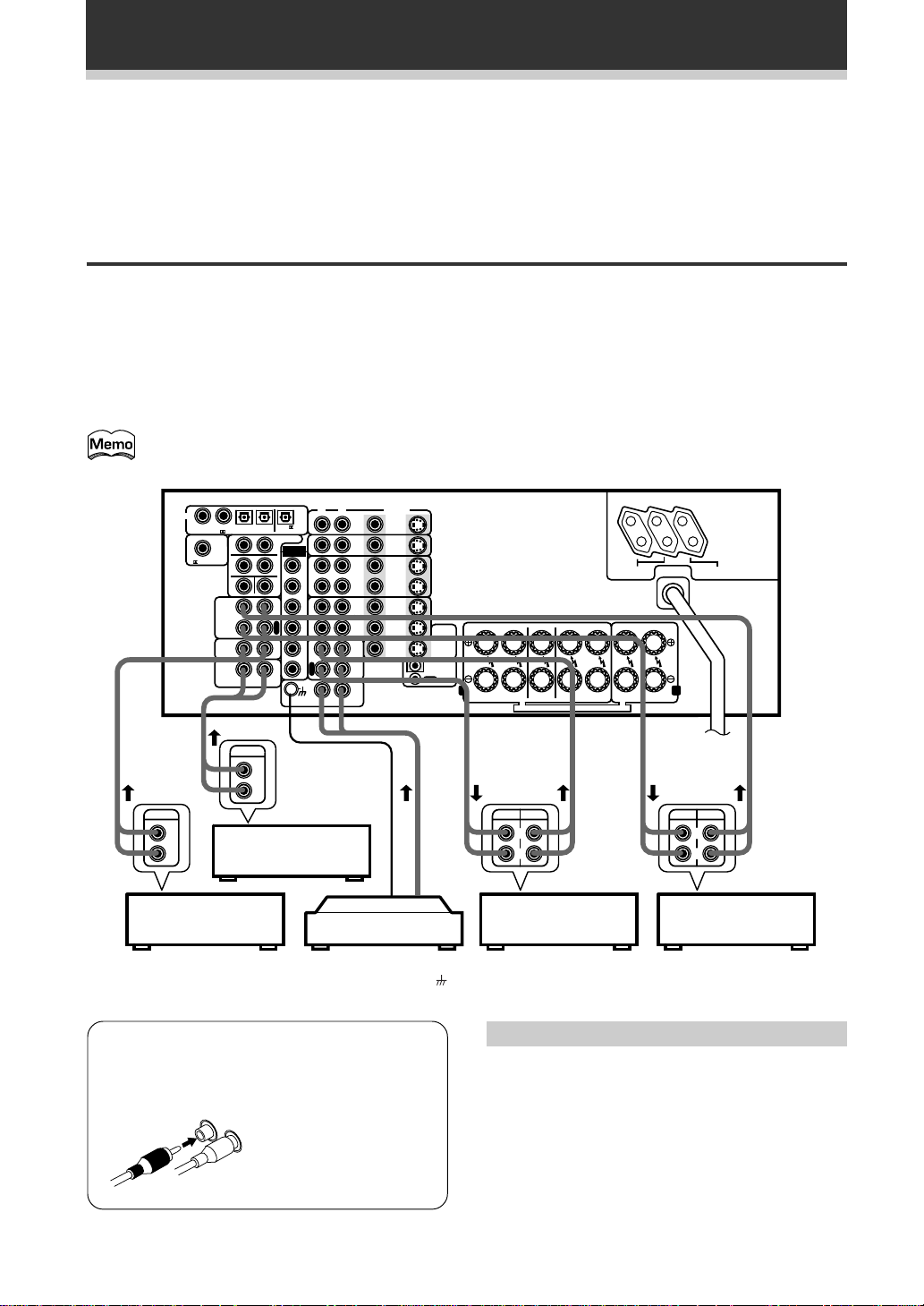
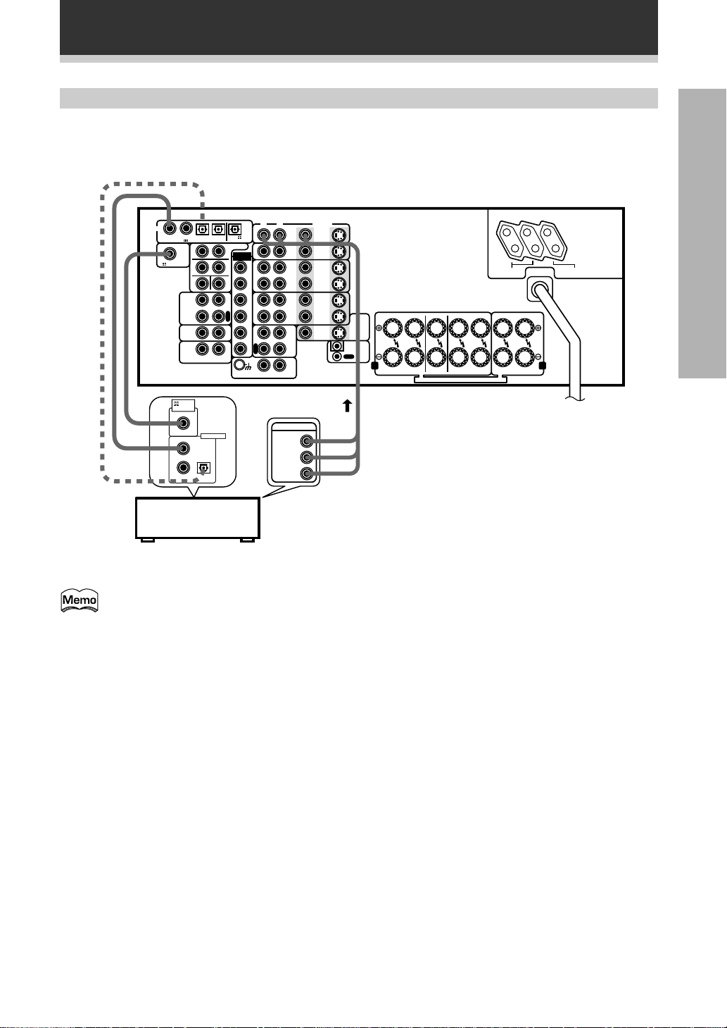
Audio Components
To begin set up connect your audio components to the jacks as shown below. These are all analog connections
and your analog audio components (turntable, cassette deck) use these jacks. Remember that for components
you want to record with you need to hook up four plugs (a set of stereo ins and a set of stereo outs), but for
components that only play (like a turntable) you only need to hook up one set of stereo plugs (two plugs). To use
DTS surround sound features you must hook up your digital components to the digital inputs but it is also a good
idea to hook up your digital components to analog audio jacks. If you want to record to/from digital components
(like an MD) to/from analog components you must hook up your digital equipment with these analog
connections. See p.10-11 for more on digital connections.
The arrows indicate the direction of the audio signal.
The illustration is not applicable to the UK model.
OUTPUT
L
R
CD player
DIGITAL
1
234
PCM/ /DTS/MPEG IN
S
R
RF IN
F
R
C
TAPE2
MONITOR
CD
LINE/
TUNER
RL
OUTPUT
FM/AM Tuner
PCM/ /DTS
/MPEG OUT
PREOUT
S
EXTERNAL
L
DECODER
L
S
W
P
L
A
Y
R
E
C
I
N
I
N
RL
IN
FLF
F
R
S
L
S
R
P
P
L
L
C
A
A
Y
Y
R
S
E
W
C
PHONO
VCR1
/DVR
VCR2
TAPE1
/CD-R
VIDEO
DVD
S
/LD
IN
IN
TV/
S
SAT
IN
IN
S
IN
IN
S
OUT
OUT
S
IN
IN
S
OUT
OUT
VIDEO
OUT
MD/
IN
L
R
Turntable
If your turntable has a ground
wire, connect it to the
(signal ground) terminal.
FR FL C SR SL R L
TO
MONITOR
TV
S
OUT
IN
CONTROL
OUT
A B
FRONT
CENTER
SPEAKERS
SURROUND
SPEAKERS
SPEAKER
SEE INSTRUCTION MANUAL SE REPORTER AU MODE D’EMPLOI
REC PLAY
L
R
MD recorder
or Cassette deck
SWITCHED
TOTAL 100W MAX
FRONT
SPEAKERS
AC OUTLETS
UNSWITCHED
100W MAX
REC PLAY
L
R
Cassette deck
(with REC monitor)
7 Audio cords
Use audio cords (not supplied) to connect the
audio components.
Connect red plugs to R
R
L
(right) and white plugs to
L (left).
Be sure to insert
completely.
8
En
Cassette deck placement
Depending on where the cassette deck is placed,
noise may occur during playback of your cassette
deck which is caused by leakage flux from the
transformer in the amplifier. If you experience noise,
move the cassette deck farther away from the
amplifier.
Page 9
Connecting Your Equipment
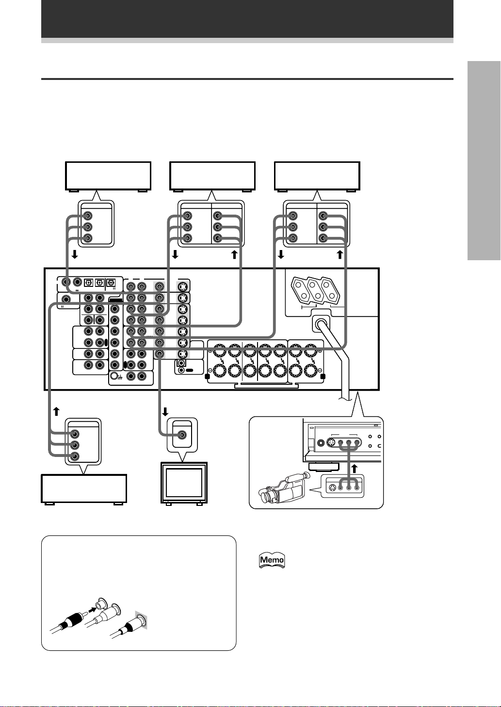
Video Components
Connect your video components to the jacks as shown below. Regarding digital video components (like a DVD),
you must use the analog connections pictured on this page for the video signal but in order to use Dolby Digital/
DTS you should hook up their audio to a digital input (see the next page). It is also a good idea to hook up your
digital components with analog audio connections as well (see the previous page). To cover all possible laser
discs a DVD/LD player or LD player requires an analog connection (as shown here) and two digital connections
(see page 11).
PREPARATION
DVD player
(or LD player)
OUTPUT
VIDEO
L
R
DIGITAL
1
234
PCM/ /DTS/MPEG IN
RF IN
TAPE2
MONITOR
CD
LINE/
TUNER
OUTPUT
S
R
F
R
C
RL
PCM/ /DTS
/MPEG OUT
PREOUT
S
EXTERNAL
L
DECODER
L
S
W
P
L
A
Y
R
E
C
I
N
I
N
VIDEO
L
R
TV tuner
(or Satellite tuner)
Video deck (1) Video deck (2)
OUTPUT INPUT
VIDEO
L
R
RL
IN
FLF
F
R
S
L
S
R
P
P
L
L
C
A
A
Y
Y
R
S
E
W
C
PHONO
TAPE1
VIDEO
DVD
S
/LD
IN
IN
TV/
S
SAT
IN
IN
S
IN
IN
VCR1
/DVR
S
OUT
OUT
S
IN
IN
VCR2
S
OUT
OUT
MONITOR
S
VIDEO
OUT
MD/
/CD-R
IN
IN
OUT
OUT
CONTROL
INPUT
VIDEO
L
R
FR FL C SR SL R L
TO
TV
A B
FRONT
CENTER
SPEAKER
SURROUND
SPEAKERS
SPEAKERS
SEE INSTRUCTION MANUAL SE REPORTER AU MODE D’EMPLOI
7 Front
VIDEO
OUTPUT INPUT
VIDEO
L
R
SWITCHED
TOTAL 100W MAX
FRONT
SPEAKERS
5-CHANNEL EQUAL POWER OUTPUT
PHONES
VIDEO
L
R
S-VIDEO
AC OUTLETS
UNSWITCHED
100W MAX
VIDEO INPUT
VIDEO
L AUDIO R
The illustration
is not applicable
to the UK
model.
VIDEO
EXTERNAL
DECODER IN DIRECT
SPEAKERS
Video
camera
(etc.)
TV
(monitor)
VIDEO INPUT
LV
R
7 Audio/Video cords
Use audio/video cords (not supplied) to connect
the video components and a video cord to
connect the monitor TV.
R
L
Connect red plugs
to R (right), white
plugs to L (left),
VIDEO
and the yellow
plugs to VIDEO.
Be sure to insert
completely.
Front video connections are accessed via the front
panel input selector as "VIDEO."
If your video components have S-video
jacks, you could use S-video cords (not
supplied) to connect them on the back of
the amplifier.
However, if you use S-video cords for
your video hook ups you must also hook
up your TV with S-video connections.
Conversely, if you use regular composite
video cords for video hook ups, you
should use them for your TV as well.
9
En
Page 10
Connecting Your Equipment
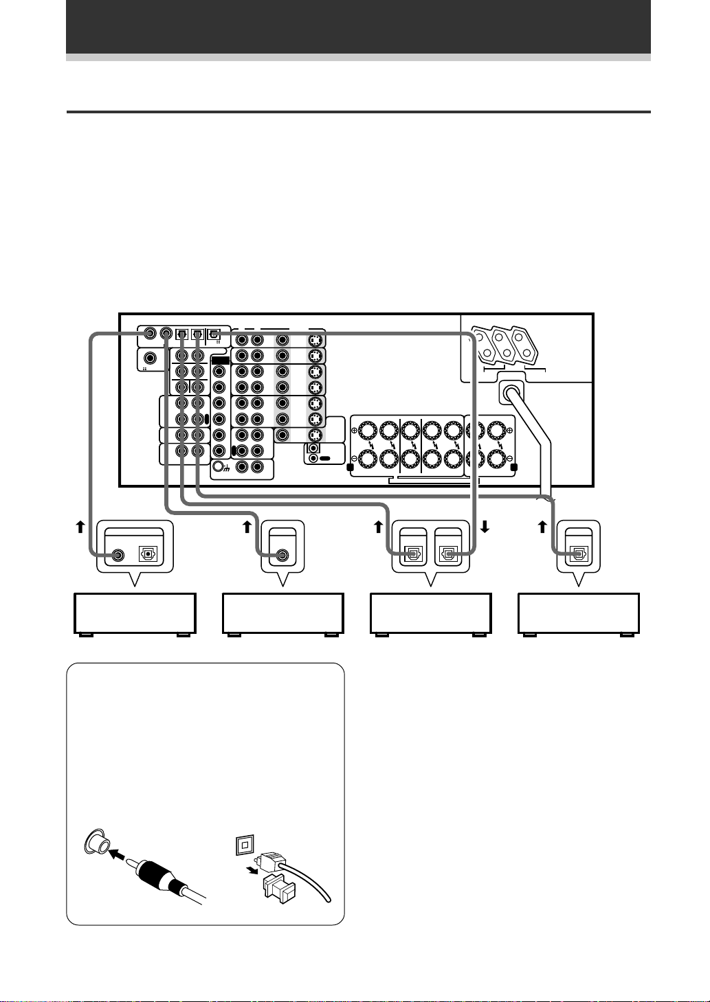
Digital Connections
In order to use MPEG/Dolby Digital/DTS soundtracks you need to make digital audio connections. You can do
this by either coaxial or optical connections (you don’t need to do both). The quality of these two types of
connections is the same but since some digital components only have one type of digital terminal, it is a matter
of matching like with like (for example, the coaxial out from the component to coaxial in on the amplifier). The
VSA-E07 has two coaxial and two optical inputs for a total of four digital inputs. You can assign the jacks to the
proper component(s). Refer to “DIGITAL INPUT SELECT” on page 36. A DVD/LD player or LD player should be
connected to a digital jack and the special
(see the previous page).
Connect your digital components as shown below. There is one digital out jack which is marked PCM/
MPEG OUT. If you connect this to the optical input on a digital recorder (currently these include MD, DAT and
CD-R) you can make direct digital recordings with this unit.
2 RF jack (if the LD player has one) as well as a pair of analog jacks
2/DTS/
The illustration is not applicable to the UK model.
DIGITAL
DIGITAL OUT
OPT.
1
234
PCM/ /DTS/MPEG IN
S
R
RF IN
F
R
C
TAPE2
MONITOR
CD
LINE/
TUNER
RL
PCM/ /DTS
/MPEG OUT
PREOUT
S
EXTERNAL
L
DECODER
L
S
W
P
L
A
Y
R
E
C
I
N
I
N
RL
IN
FLF
F
R
S
L
S
R
P
P
L
L
C
A
A
Y
Y
R
S
E
W
C
VIDEO
DVD
S
/LD
IN
IN
TV/
S
SAT
IN
IN
S
IN
IN
VCR1
/DVR
S
OUT
OUT
S
IN
IN
VCR2
S
OUT
OUT
VIDEO
OUT
MD/
TAPE1
/CD-R
IN
PHONO
DIGITAL DIGITAL
OUT
CD player MD recorderDVD player
7 Digital audio cords/Optical cables
Commercially available digital audio coaxial cords
(standard video cords can also be used) or
optical cables (not supplied) are used to connect
digital components to this amplifier.
When you use optical digital input or output
terminals, pull off the caps and insert the plugs.
Be sure to insert completely.
FR FL C SR SL R L
TO
MONITOR
TV
S
OUT
IN
CONTROL
OUT
A B
FRONT
SPEAKERS
SEE INSTRUCTION MANUAL SE REPORTER AU MODE D’EMPLOI
CENTER
SPEAKER
DIGITAL
OUT
SURROUND
SPEAKERS
IN
DIGITAL INPUT JACKS
The default setting for each of the digital inputs is
described below.
DIGITAL 1: DVD/LD
DIGITAL 2: CD
DIGITAL 3: MD
DIGITAL 4: TV/SAT
2 RF IN: DVD/LD
SWITCHED
TOTAL 100W MAX
FRONT
SPEAKERS
AC OUTLETS
UNSWITCHED
100W MAX
DIGITAL
OUT
TV tuner
(or Satellite tuner)
Digital audio cord
(or standard video cord)
10
En
Optical cable
Page 11
Example Connection for a DVD/LD or LD player
Connecting Your Equipment
Make sure you connect your DVD/LD or LD players using both the 2 RF jack and a coaxial or optical
connection. If your player has an
2 RF output this will ensure you can use all LDs (see p. 36).
The illustration is not applicable to the UK model.
DIGITAL
1
234
PCM/ /DTS/MPEG IN
RF IN
TAPE2
MONITOR
CD
LINE/
TUNER
RF OUT
(AC-3)(LD)
1
23
S
R
F
R
C
RL
DIGITAL OUT
PCM (OPT.)
PCM/ /DTS
/MPEG OUT
PREOUT
S
EXTERNAL
L
DECODER
L
S
W
P
L
A
Y
R
E
C
I
N
I
N
RL
IN
FLF
F
R
S
L
S
R
P
P
L
L
C
A
A
Y
Y
R
S
E
W
C
VCR1
/DVR
VCR2
TAPE1
/CD-R
PHONO
OUTPUT
VIDEO
L
R
VIDEO
DVD
S
/LD
IN
IN
TV/
S
SAT
IN
IN
S
IN
IN
S
OUT
OUT
S
IN
IN
S
OUT
OUT
VIDEO
OUT
MD/
IN
OUT
FR FL C SR SL R L
TO
MONITOR
TV
S
OUT
IN
CONTROL
A B
CENTER
FRONT
SPEAKER
SPEAKERS
SEE INSTRUCTION MANUAL SE REPORTER AU MODE D’EMPLOI
SURROUND
SPEAKERS
SWITCHED
TOTAL 100W MAX
FRONT
SPEAKERS
AC OUTLETS
UNSWITCHED
100W MAX
DVD/LD player
or LD player
PREPARATION
Be sure to make either a digital coaxial or digital optical connection (pictured as DIGITAL jack 1 or
DIGITAL jack 3 in this diagram) as well, but you DON'T need to make both. Also, be sure to assign the
jacks to the proper component(s) with the DIGITAL INPUT SELECT procedure (see p. 36).
11
En
Page 12
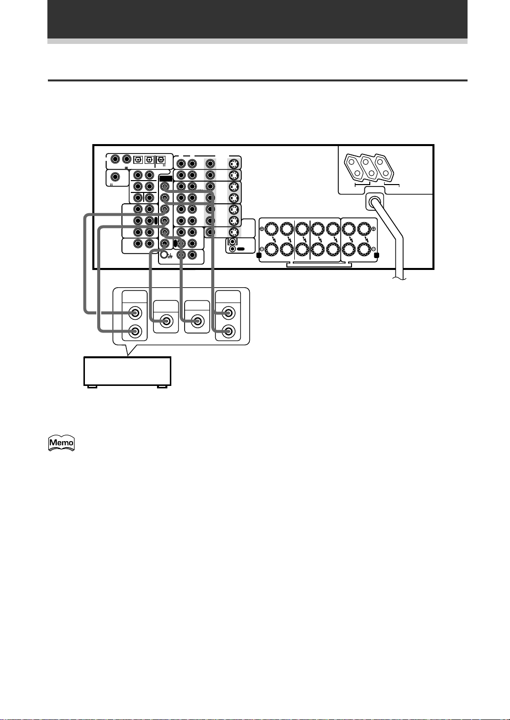
Connecting Your Equipment
External Decoder Input
In some cases you may need an external decoder to play special analog or DVD sources. If you find you need an
external decoder hook one up as shown below, but for most people this component is unnecessary. (See p.47)
The illustration is not applicable to the UK model.
DIGITAL
»
1
234
PCM/ /DTS/MPEG IN
RF IN
TAPE2
MONITOR
CD
LINE/
TUNER
SURROUND
OUTPUT
S
R
F
R
C
RL
L
PCM/ /DTS
/MPEG OUT
PREOUT
S
EXTERNAL
L
DECODER
IN
L
S
W
P
L
A
Y
R
E
C
I
N
I
N
»
SUB
WOOFER
FLF
F
R
S
L
S
R
C
S
W
RL
P
P
L
L
A
A
Y
Y
R
E
C
»
CENTER
PHONO
TAPE1
DVD
/LD
IN
TV/
SAT
IN
IN
VCR1
/DVR
OUT
IN
VCR2
OUT
MD/
/CD-R
IN
R
Components equipped with 5.1
channel analog output jacks
VIDEO
OUT
OUT
VIDEO
OUT
»
FRONT
OUTPUT
S
IN
S
IN
S
IN
S
S
IN
S
OUT
FR FL C SR SL R L
TO
MONITOR
TV
S
OUT
IN
CONTROL
A B
FRONT
CENTER
SPEAKERS
SPEAKER
SEE INSTRUCTION MANUAL SE REPORTER AU MODE D’EMPLOI
SURROUND
SPEAKERS
SWITCHED
TOTAL 100W MAX
FRONT
SPEAKERS
AC OUTLETS
UNSWITCHED
100W MAX
L
R
12
En
You can't use the tuner and phono functions with an external decoder input.
Page 13
Connecting Your Equipment
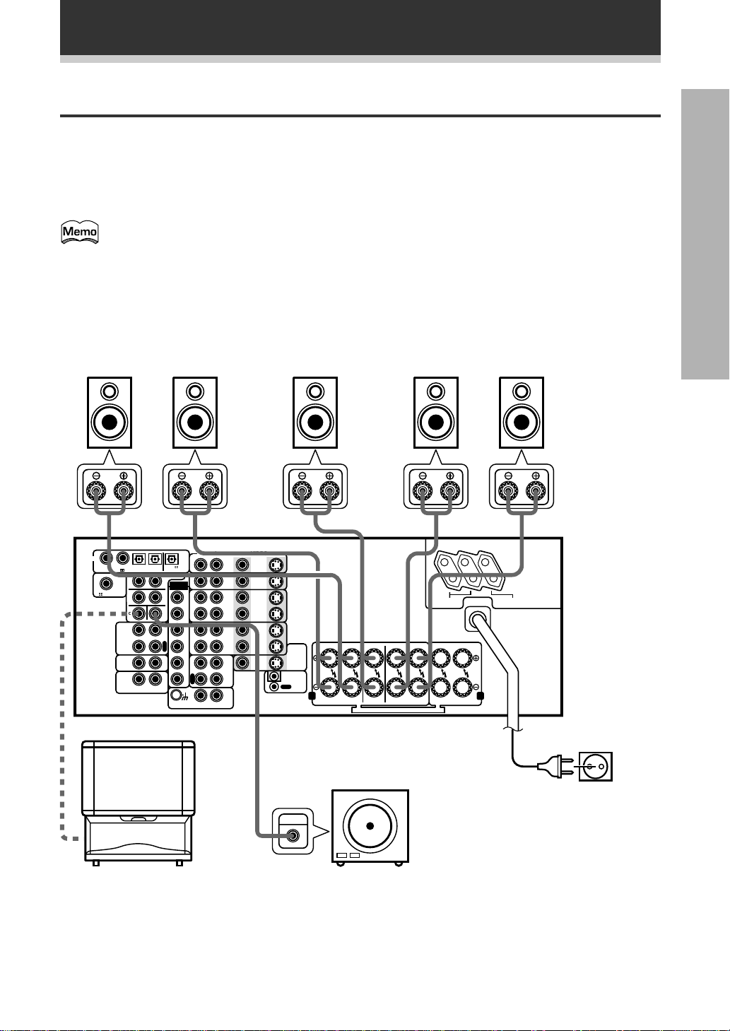
Speakers
A full complement of six speakers is shown here but, naturally, everyone's home set up will vary. Simply
connect the speakers you have in the manner described below. The VSA-E07 will work with just two stereo
speakers (called "front" speakers in the diagram) but the amplifier is designed to be used with at least three
speakers.
Make sure you connect the speaker on the right to the right terminal and the speaker on the left to the left
terminal. Also make sure the positive and negative (+/–) terminals on the amplifier match those on the speakers.
The VSA-E07 has two speaker systems, A & B. A is the main system supporting the full complement of
surround sound speakers. If you switch on both A & B speaker systems, only front speakers and the
sub-woofer will be audible. No sound will come from the center or surround speakers but multi channel
sources will be down-mixed to the active speakers so no sound will be lost. Similarly, if you choose just
the B system you‘ll only hear the front speakers connected to the B system and multi channel sources
will be down-mixed to these two speakers.
Please use speakers with a nominal impedance rated 6Ω-16Ω.
PREPARATION
Front Speakers (A)
L C SR SLR
DIGITAL
1
234
PCM/ /DTS
S
R
F
R
C
RL
/MPEG OUT
S
L
L
S
W
P
L
A
Y
R
E
C
I
N
I
N
PCM/ /DTS/MPEG IN
RF IN
TAPE2
MONITOR
CD
LINE/
TUNER
TV
(To be used
as the center
speaker)
PREOUT
EXTERNAL
DECODER
Center Speaker Surround Speakers
RL
IN
FLF
F
R
S
L
S
R
P
P
L
L
C
A
A
Y
Y
R
S
E
W
C
PHONO
VCR1
VCR2
TAPE1
/CD-R
VIDEO
DVD
S
/LD
IN
IN
TV/
S
SAT
IN
IN
S
IN
IN
/DVR
S
OUT
OUT
S
IN
IN
S
OUT
OUT
VIDEO
OUT
MD/
IN
IN
OUT
FR FL C SR SL R L
TO
MONITOR
TV
S
OUT
CONTROL
A B
CENTER
FRONT
SPEAKER
SPEAKERS
SEE INSTRUCTION MANUAL SE REPORTER AU MODE D’EMPLOI
SURROUND
SPEAKERS
SWITCHED
TOTAL 100W MAX
FRONT
SPEAKERS
AC OUTLETS
UNSWITCHED
100W MAX
The illustration
is not applicable
to the UK
model.
Powered sub woofer
Be sure to complete all other
INPUT
connections before connecting
this unit to the AC power source.
When using the speaker on your TV as
the center speaker, connect the
CENTER PREOUT jack on this unit to
the audio input jack on your TV. In this
case, the center speaker shown is
unnecessary.
13
En
Page 14
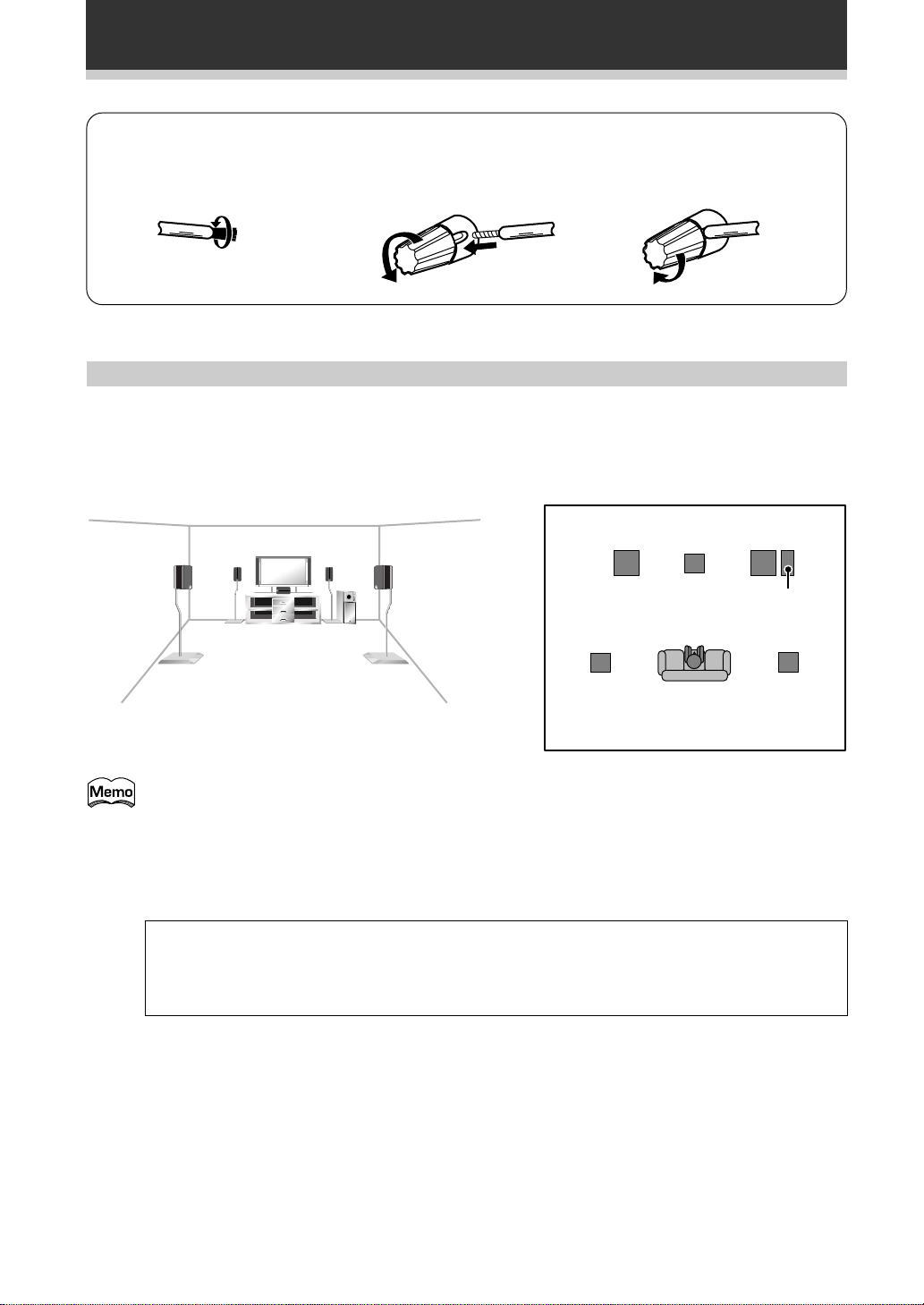
Connecting Your Equipment
Surround
Left
Surround
Right
Listening
Position
Front
Left
Front
RightCenter
Sub
Woofer
7 Speaker terminals
1 Twist exposed wire
strands together.
10 mm
2 Loosen speaker terminal
and insert exposed wire.
3 Tighten terminal.
Speaker placement
If you have a multiple speaker arrangement the placement of the speakers is extremely important. To achieve
the best possible surround sound, install your speakers as shown below. Make sure all speakers are installed
securely to prevent accidents and improve sound quality. Be sure to consult your speaker manuals for the best
placement of the speakers. Some speakers are designed to be floor-standing but others benefit greatly from
speakers stands which raise them off the floor.
14
En
• Install the left and right front speakers at equal distances from the TV.
• When installing speakers near the TV, we recommend using magnetically shielded speakers to
prevent possible interference such as distortion in the color of the TV screen. If you do not have
magnetically shielded speakers and notice discoloration of the TV screen, place the speakers farther
away from the TV.
• Install the center speaker above or below the TV so that the sound of the center channel is localized
at the TV screen.
CAUTION:
When installing the center speaker on top of the TV, be sure to secure it with tape or some other
suitable means. Otherwise, the speaker may fall from the TV due to external shocks such as
earthquakes, and it may lead to endangering those nearby or damaging the speaker.
• If possible, install the surround speakers slightly above ear level.
• It may be difficult to obtain a cohesive surround effect if the surround speakers are installed farther
away from the listening position than the front and center speakers.
Page 15

Connecting Your Equipment
Connecting Additional Amplifiers
Although the VSA-E07 has more than sufficient power for any home use, it is possible to add additional
amplifiers to your system. If you want to use separate amplifiers to power your speakers, make the
connections shown below.
PREPARATION
L-Audio
(MONO)
PIONEER
projection TV
(for center
channel)
AUDIO
IN
L
R
DIGITAL
1
234
PCM/ /DTS/MPEG IN
S
R
RF IN
F
R
C
TAPE2
MONITOR
CD
LINE/
TUNER
(or)
RL
PCM/ /DTS
/MPEG OUT
PREOUT
S
EXTERNAL
L
DECODER
L
S
W
P
L
A
Y
R
E
C
I
N
I
N
IN
Amplifier
(for center
channel)
AUDIO
IN
RL
DVD
/LD
IN
TV/
SAT
IN
FLF
IN
VCR1
/DVR
F
OUT
R
S
IN
L
VCR2
S
OUT
R
P
P
L
L
C
A
A
MD/
Y
Y
TAPE1
/CD-R
R
S
E
W
C
IN
PHONO
L
R
VIDEO
S
IN
S
IN
S
IN
S
OUT
S
IN
S
OUT
VIDEO
OUT
Amplifier
(for surround
channels)
AUDIO
IN
L
R
FR FL C SR SL R L
TO
MONITOR
TV
S
OUT
IN
CONTROL
OUT
A B
FRONT
CENTER
SPEAKERS
SURROUND
SPEAKERS
SPEAKER
SEE INSTRUCTION MANUAL SE REPORTER AU MODE D’EMPLOI
The illustration is not applicable to the UK model.
Amplifier
(for front
channels)
AUDIO
IN
SWITCHED
TOTAL 100W MAX
FRONT
SPEAKERS
Powered
sub woofer
INPUT
L
R
AC OUTLETS
UNSWITCHED
100W MAX
Power Connections (AC OUTLETS) (Except for the UK
model.)
[SWITCHED TOTAL 100 W MAX]
Power supplied through these outlets is turned on and off by the amplifier’s POWER switch. Total electrical
power consumption of connected equipment should not exceed 100 W.
[UNSWITCHED 100 W MAX]
Power flows continually to this outlet, regardless of whether the amplifier is switched ON or OFF. Electrical
power consumption of the connected equipment should not exceed 100 W.
CAUTION!
• Do not connect appliances with high power consumption such as heaters, irons, or television sets to the
AC OUTLETS in order to avoid overheating or fire risk. This can cause the amplifier to malfunction.
• The equipment should be disconnected by removing the mains plug from the wall socket when not in
regular use, e.g. when on vacation.
15
En
Page 16
Displays and Controls
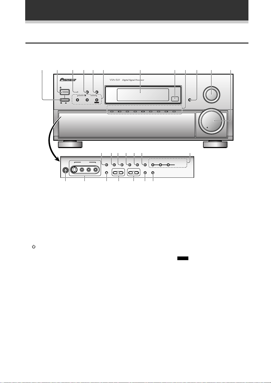
Front Panel
All the controls on the front panel are explained and/or referenced here. To open the front panel push gently on
the lower third of the panel.
123456 7 890 =-
AUDIO / VIDEO MULTI - CHANNEL AMPLIFIER
STANDBY/ON
OFF ON
DSP
STANDBY
THX CINEMA ADVANCED STANDARD
STEREO
MODE
/DTS
MPEG
VIDEO VCR 1/DVR VCR 2 DVD /LD
TV/SAT
FL
DIMMER
MD/TAPE 1/
LINE/
CD
PHONO
CD-R
TUNER
MIN MAX
INPUT
SELECTOR
MASTER
VOLUME
~!@#$%
PHONES
S-VIDEO VIDEO
VIDEO INPUT
L AUDIO R
EXTERNAL
DECODER IN
DIRECT LOUDNESS MIDNIGHT
- BASS +
+¡ _ ) ( * &
1 Main power (_ ON/ — OFF) button
If the button is OFF (—), the power of the
amplifier is shut off and the STANDBY/ON button
on the amplifier or the remote control do not
function. Pressing the button again will turn the
amplifier ON (_) and the amplifier enters the
standby mode. In the standby mode, you can
turn on the amplifier using the STANDBY/ON
button on the amplifier or the remote control.
2 STANDBY/ON button
Press to switch the amplifier ON or into
STANDBY mode.
3 STANDBY indicator
Lights when the amplifier is in STANDBY mode.
(Please note that this amplifier consumes a small
amount of power (1.0 W) during the standby
mode.)
4 DSP MODE button (See p.41-42)
Press repeatedly to select a DSP sound mode
(HALL 1, HALL 2, JAZZ, DANCE, THEATER 1, or
THEATER 2). Use these modes to produce
surround sound from standard (two channel)
stereo sources and create different listening
environments.
^
EFFECT/
SIGNAL
DIGITAL
CHANNEL
SELECT
NR
INPUT ATTSPEAKERS
- TREBLE +
5 STEREO button (See p.41-42)
6 2/DTS buttons (See p.40,42 & 68-70)
7 Display (See p.18)
8 Remote sensor
9 Source indicators
0 FL DIMMER button (See p.49)
– LEVEL +
SELECT
TAPE 2
MONITOR
LEVEL CONTROL
5–CHANNEL EQUAL POWER OUTPUT
Press to select the STEREO sound mode. In this
mode, sound comes from the front (left and right)
speakers only.
THX CINEMA : Press to select the HOME THX
CINEMA mode when listening to Dolby Digital,
Dolby Pro Logic or DTS a variety of other
sources.
ADVANCED THEATER : Press to select one of
the four Advanced Theater modes.
STANDARD (
MPEG
) : Press repeatedly to select
the standard mode and MPEG mode.
Point the remote control toward the remote
sensor to operate the amplifier.
Shows the source currently selected.
Use to adjust the brightness of the main display.
16
En
Page 17

Displays and Controls
- INPUT SELECTOR dial
Turn to select a source component. The source
indicators show the current component:
DVD/LD : DVD player or LaserDisc player.
TV/SAT : TV tuner or satellite tuner.
CD : Compact Disc player.
MD/TAPE 1/CD-R : Tape deck or Mini Disc
recorder connected to MD/TAPE 1/CD-R inputs/
outputs.
LINE/TUNER : FM/AM tuner.
PHONO : Turntable.
VIDEO : Video camera (etc.) connected to the
VIDEO INPUT on the front panel.
VCR 1/DVR : Video cassette recorder connected
to VCR 1/DVR inputs.
VCR 2 : Video cassette recorder or other
component connected to VCR 2 inputs.
= MASTER VOLUME
Adjusts the overall amplifier volume.
~ EXTERNAL DECODER IN button (See
p.47)
Use to hook up an external component that can
decode other types of signals and input them into
the amplifier.
! DIRECT button (See p.49)
Switches DIRECT playback on or off. Use to
bypass the tone controls and channel level for the
most accurate reproduction of a program source.
It will automatically put the amplifier in STEREO
mode for the function being used for DIRECT
playback.
@ LOUDNESS button (See p.48)
Switches the LOUDNESS mode on or off.
# MIDNIGHT button (See p.47)
Switches the MIDNIGHT listening mode on or
off.
$ DIGITAL NR button (See p.46)
Switches the DIGITAL NR on or off (STEREO
mode only).
% SIGNAL SELECT button (See p.45)
Use to select the signal from the digital
components.
Press SIGNAL SELECT repeatedly to select one
of the following:
ANALOG : To select an analog signal.
DIGITAL : To select an optical or coaxial digital
signal.
AC-3 RF : To select an AC-3 RF signal.
AUTO : This is the default. If there are both
analog and digital input signals, the amplifier
automatically selects the best possible signal.
^ EFFECT/CHANNEL SELECT LEVEL(–/+)
buttons
EFFECT : Use these buttons to increase or
decrease the amount of effect applied in a DSP or
Advanced Theater mode. When the amount of
effect is increased in a DSP/Advanced Theater
mode, the characteristics of that mode become
stronger and more noticeable. The scale ranges
from 10-90 with 70 as the default setting. First
turn on the DSP or ADVANCED Theater you want
(by pressing the DSP MODE/ADVANCED button
until you get the mode) and then increase or
decrease the amount of effect.
CHANNEL : You may want to adjust the channels
when listening to some sound sources. Use this
button to select the channel you want to adjust.
–/+ : Use these buttons to select the amount of
effect in a sound mode or to adjust the channel
level when making surround sound settings.
& TAPE 2 MONITOR button (See p.62)
Selects the tape deck (MD recorder, etc.)
connected to the TAPE 2 MONITOR inputs/
outputs. Allows monitoring of a recording as it's
being made.
* INPUT ATT button
Use to lower the input level of an analog signal
that is too powerful, thus causing the amplifier to
distort (the overload indicator will light furiously).
( TREBLE (–/+) button (See p.48)
Use to adjust the high frequencies.
) BASS (–/+) button (See p.48)
Use to adjust low frequencies.
_ SPEAKERS (A/B) buttons
A is the primary setting. It plays all speakers
hooked up to the A system. A & B setting only
plays the front speakers of both the A & B
systems and the sub-woofer. Multi channel
sources will be down-mixed to these speakers so
no sound will be lost. B setting only plays the
front speakers connected to the B system and
multi channel sources will be down-mixed to
these two speakers.
A A+B OFFB
+ VIDEO INPUT jacks (See p.9)
S-VIDEO : Video input for connecting a video
camera (etc.), that has an S-Video out.
VIDEO / AUDIO (L/R) : Video input for
connecting a video camera, etc. that has standard
video/audio outputs.
¡ PHONES jack
Connect headphones for private listening (no
sound will be heard through the speakers).
PREPARATION
17
En
Page 18
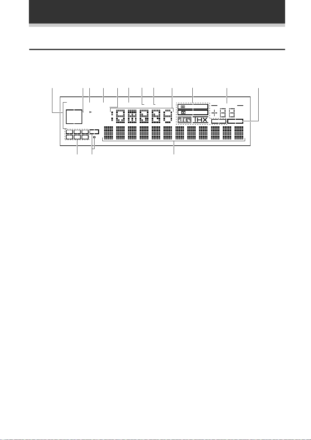
Displays and Controls
Display
All the display information is explained and /or referenced here.
1234567890 -
SELECT
OVER
SP AB
LFE
R
H.P
ANALOG
DIGITAL
AC-3RF
AUTO
AC-3DTS MPEG
C
L
LS LS RS
1 SIGNAL SELECT indicators
Light to indicate the type of input signal selected
for the current component (see "Front Panel", %,
SIGNAL SELECT).
ANALOG : Lights when analog signals are
assigned.
DIGITAL : Lights when digital audio signals are
selected.
AC-3 RF : Lights when AC-3 RF signals are
assigned.
AUTO : Lights when the receiver is set to select
the input signal automatically.
AC-3 : Lights when a source with Dolby Digital
signals is played.
DTS : Lights when a source with DTS audio
signals is played.
MPEG: Blinks when the MPEG mode is selected,
and lights when a source with MPEG audio
signals is played.
2 Speaker indicators
Light to indicate the current speaker system (see
"Front Panel", _, SPEAKERS (A/B)).
SP # A : Lights when speaker system A is
selected.
SP # B : Lights when speaker system B is
selected.
SP # AB : Lights when speaker systems A & B
are selected.
MIDNIGHTLOUDNESSATTSIGNAL
DSP
STEREO
PRO LOGIC
DIGITAL
MPEG
VOLUME
dB
TAPE 2
~!@
3 Analog level indicators
OVER : If "ANALOG" is selected in SIGNAL
SELECT, this indicator lights to show that an
excessively strong signal is being processed.
When this occurs, press INPUT ATT on the front
panel to attenuate (lower) the signal. Also, when
"DIGITAL" is selected in SIGNAL SELECT, this
indicator lights to show that a source containing
an excessive amount of information is being
processed. If this occurs, see p. 42.
ATT : Lights when INPUT ATT is used to reduce
the level of the input signal (available in ANALOG
mode only).
4 LOUDNESS indicator (See p.48)
Lights when the LOUDNESS mode is on.
5 H.P (headphones)
Lights when headphones are connected to the
PHONES jack (speakers A and B turn off
automatically).
6 MIDNIGHT indicator (See p.47)
Lights when the MIDNIGHT listening mode is on.
7 DSP indicator (See p.41-42)
Light when a DSP or Advanced Theater mode is
selected.
8 STEREO indicator (See p.41-42)
Lights when a STEREO mode is selected.
=
18
En
Page 19

9 Function indicator
Displays the function.
0 2 Surround/dts mode indicators
2 DIGITAL : When the 2 Surround/dts mode
on the amplifier is on, this indicator lights to
indicate playback of a Dolby Digital signal.
However, 2 PRO LOGIC lights during 2 channel
playback of Dolby Digital.
2 PRO LOGIC : When the 2 Surround/dts
mode on the amplifier is on, this indicator lights
during 2 channel playback. ( Both B or A+B
speaker systems turn off automatically when
headphones are plugged.)
dts : Lights when DTS signals are input.
THX: Lights when the HOME THX CINEMA
mode is selected.
MPEG: Lights when the MPEG mode is selected.
- MASTER VOLUME indication
Displays current level of master volume.
= TAPE 2 indicator
Lights when the TAPE 2 monitor is on.
~ Character display
Displays sound modes, general information, etc.
Displays and Controls
PREPARATION
! LFE indicator
LFE (Low Frequency Effects) indicator lights to
indicate that the program source contains an LFE
channel. The indicator under the LFE lights during
actual playback of the LFE signals (LFE signals
are not present in all parts of the soundtrack).
@ Program Format indicator
When a Dolby Digital or DTS signal is input, the
following indicators light to show the channels
being played back.
L : Left front*1*2, C : Center*1, R : Right front*1*2,
LS : Left surround*
RS : Right surround*
*1: Indicates 5.1ch Dolby Digital or DTS playback.
*2: Indicates Dolby surround playback.
1
, S : Surround (mono)*2,
1
19
En
Page 20
Displays and Controls
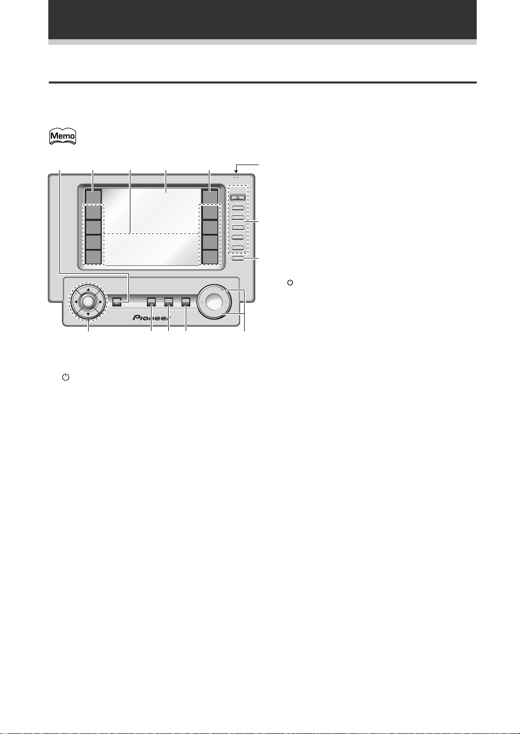
Remote Control
These pages describe the buttons on the remote control used to operate the amplifier. Since the screen on this
LCD remote control changes when you select a different function, explanations of buttons for controlling other
components/functions can be found in the sections for those components/functions.
To turn on the remote control touch it anywhere on the screen.
5 REMOTE SETUP button.
TV
CONTROL
FUNCTION
CH +
CH –
VOL +
VOL –
FUNCTION
9
6
Use to customize the remote control functions
and the remote control itself. (See "Remote
Control of Other Components" starting on p.50)
6 BACK LIGHT switch
7
Switch the BACK LIGHT on or off (see p.7)
7 TV CONTROL buttons
The following buttons are used to control the TV
8
only and can be used once they are preset to
control your TV.
: Press to turn the power of the TV on/off.
FUNCTION : Press TV FUNC to select the TV’s
input.
CH +/– : Use these buttons to change the
channel of the TV.
VOL +/– : Press to control the volume of the TV.
8 FUNCTION button
Press to select a source. The button will cycle
through all the possible sources.
9 MASTER VOLUME button
Use to raise or lower the volume of the receiver.
12 3 4 5
MUTING
0=
REMOTE
SETUP
MD/TAPE1
CD
LINE/
TUNER
TV
CONTROL
MASTER VOLUME
+
–
AMP
DVD/LD
TV/SAT
VCR1
VCR2
SYSTEM
MULTI
OFF
STANDBY/ON
ENTER
~
OPERATION
-
1 STANDBY/ON button
Press to turn power of the amplifier on or to
STANDBY (off).
on of f
BACK LIGHT
2 AMP button
Press to switch the remote control into amplifier
mode or to get amplifier screens.
3 Function buttons
These buttons are the basic controls that switch
the mode of the amplifier and allow you to control
your other components.
DVD/LD : Press to switch the remote control into
DVD/LD mode.
TV/SAT : Press to switch the remote control into
TV/SAT (satellite tuner) mode.
VCR 1 : Press to switch the remote control into
VCR 1 mode.
VCR 2 : Press to switch the remote control into
VCR 2 mode.
MD/TAPE 1 : Press to switch the remote control
into MD/TAPE 1 mode.
CD : Press to switch the remote control into CD
mode.
LINE/TUNER : Press to switch the remote
control into TUNER mode.
TV CONTROL : Press so that the remote control
can operate the TV CONTROL commands.
4 REMOTE CONTROL screen (See p.21)
20
En
0 MUTE button
Press to mute or restore the volume.
- SYSTEM OFF button (See p.65-66)
This button turns off components in two ways.
First, when pressed it will turn off all PIONEER
components. Secondly, any component that has
programmed into the SYSTEM OFF settings will
be turned off.
For example : If you programmed power off in
the SYSTEM OFF settings for your TV and VCR,
pressing the SYSTEM OFF button will turn off
these components even if they are not PIONEER
products.
= MULTI OPERATION button
Use this button to start the MULTI OPERATION
mode. See p. 63 for how to program and use the
MULTI OPERATION mode.
~ %/fi/@/# ENTER buttons
These buttons can be used for a variety of
operations. In the SYSTEM SETUP menu, the
%/fi buttons can be used to adjust CHANNEL
DELAY or CHANNEL LEVEL.
The %/fi buttons, pressed simultaneously, can be
use to lock or unlock a setting (see p.54).
These buttons are also used to control the DVD
menu for the DVD remote control screen.
Page 21
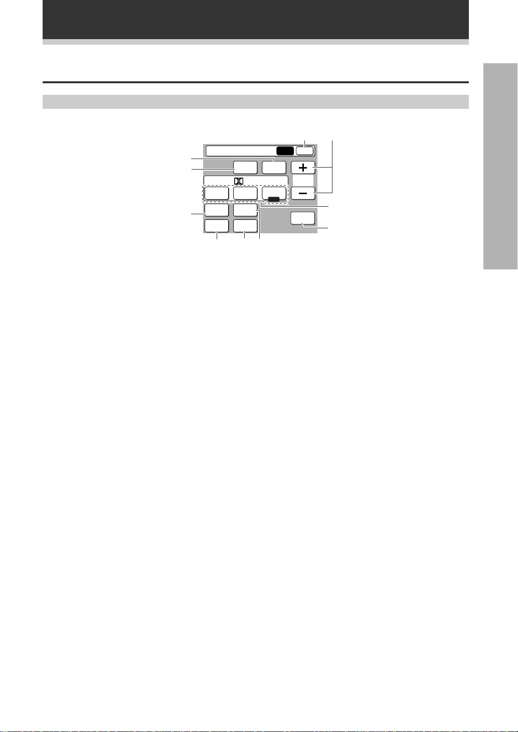
Basic Amplifier LCD Screens
Amplifier MAIN Screen
Amplifier
0
9
8
MIDNIGHT
DIGITAL
THX
NR
7
DSP STEREO
/ dts
ADVANCED
THEATER
DIRECT
LOUDNESS
STANDARD
MPEG
56
1
MAIN SUB
EFFECT
SIGNAL
SELECT
Displays and Controls
PREPARATION
2
3
4
1 Amplifier SUB button
Press this button to select the amplifier sub
screen (on the page 22) when the remote control
is on the amplifier main screen.
2 EFFECT +/– button
Use these buttons to increase or decrease the
amount of effect applied in a DSP or Advanced
Theater mode. When the amount of effect is
increased in a DSP/Advanced Theater mode the
characteristics of that mode become stronger and
more noticeable. The scale ranges from 10-90
with 70 as the default setting. First turn on the
DSP/Advanced Theater mode you want (by
pressing the DSP/Advanced Theater button until
you get the mode) and then increase or decrease
the amount of effect.
3 2/dts buttons (See p.40,42 & 68-70)
Press these buttons to put the amplifier in the
selected surround sound mode.
4 SIGNAL SELECT button (See p.45)
Press SIGNAL SELECT repeatedly to select one
of the following:
ANALOG : To select an analog signal.
DIGITAL : To select a digital signal.
AC-3 RF : To select an AC-3 RF signal.
AUTO : This is the default. If there are both
analog and digital input signal, the amplifier
automatically selects digital.
5 DIRECT button
Switches DIRECT playback on or off. Use to
bypass the tone controls and channel level for the
most accurate reproduction of a program source.
It will automatically put the amplifier in STEREO
mode for the function being used for DIRECT
playback.
6 LOUDNESS button (See p.48)
Switches the LOUDNESS mode on or off.
7 DIGITAL NR button (See p.46)
Switches the DIGITAL NR on or off (STEREO
mode only).
8 MIDNIGHT button (See p.47)
Switches the MIDNIGHT listening mode on or
off.
9 DSP button (See p.41-42)
Press repeatedly to select a DSP sound mode.
0 STEREO button (See p.41-42)
Press to select the STEREO sound mode. In this
mode, sound comes from the front (left and right)
speakers only.
21
En
Page 22

Displays and Controls
Amplifier SUB Screen
Amplifier
TAPE 2
7
MONITOR
6
INPUT
5
ATT.
1 Amplifier MAIN button
Press this button to select the amplifier main
screen (on the page 21) when the remote control
is on the amplifier sub screen.
2 BASS & TREBLE (+/–) buttons (See
p.48)
Use to adjust the high and low frequencies
(STEREO mode only).
3 SYSTEM SET UP button
Use to set up the speaker and sound systems.
For more information see "Setting Up for
Surround Sound " starting on p. 26.
4 CHANNEL LEVEL button (See p.31-32)
Use this feature to adjust the level of individual
speakers during playback of a source.
EXTERNAL
5.1CH
MAIN SUB
BASS
CH
LEVEL
4
1
TREBLE
SYSTEM
SETUP
2
3
5 INPUT ATT button
Use to lower the input level of an analog signal
that is too powerful, thus causing the amplifier to
distort (the overload indicator will light furiously).
6 EXTERNAL 5.1 CHANNEL button (See
p.47)
Use to hook up an external component that can
decode other types of signals and input them into
the VSA-E07.
7 TAPE 2 MONITOR button (See p.62)
Selects the tape deck (or MD recorder, etc.)
connected to the TAPE 2 MONITOR inputs/
outputs. Allows monitoring of a recording as it's
being made.
22
En
Page 23
Initial Set Up
U
On Screen Display
There are a number of possible ways to hook up the amplifier to your video components, like a DVD player, and
hook up to your amplifier to your TV, but some of them won't allow you to use the on-screen display of this unit.
To avoid this one simply needs to follow two rules.
1 Always use the same type of video cords to hook up your video components to the amplifier as you use to
hook up the amplifier and your TV. For example, if you use composite video cords to hook up your DVD and
the amplifier, use composite video cords to hook up the amplifier to your TV. If you use S video cords to hook
up your DVD and the amplifier, use S video cords to hook up the amplifier to your TV.
2 Always make sure your TV is set to the appropriate input channel (for example, video 1). Your TV may have a
number of input channels and if you don't select the proper one you won't be able to use this amplifier's onscreen display, or, in fact, see any picture from this amplifier at all. If you are unsure how to choose an input
channel for your TV, refer to the manual which came with your TV.
You might, for example, use both composite and S video cords to hook up your video components with this
amplifier and then use composite video cords to hook up this amplifier to your TV. This arrangement would still
NOT let you see the on screen displays from this amplifier on your TV. The best idea is just to use one type of
video cord for all your video component and TV hook ups.
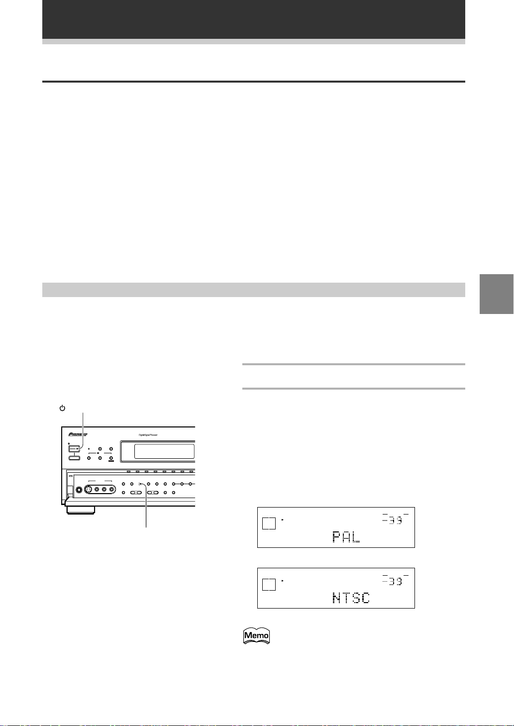
Switching video system between PAL and NTSC
This amplifier is able to use two types of video systems for its OSD (on screen display) and you need to set the
amplifier to the type of video system you have, either PAL or NTSC. If you do not match the system on the
amplifier with your home system no OSD will appear on your TV. People with multi-system TVs, don’t need to
worry about changing the setting. If necessary, follow the instructions below to switch the type of video
system.
UP
SET
STANDBY/ON
AUDIO/VIDEO MULTI-CHANNEL AMPLIFIER
STANDBY/ON
DSP
STEREO
STANDBY
MODE
/DTS
THX CINEMA ADVANCED STANDARD
VIDEO INPUT
MPEG
L AUDIO R
—OFF _ON
PHONES S-VIDEO VIDEO
N∫z¿x?≥
VIDEO VCR 1/DVR VCR 2 DVD /LD
EXTERNAL
DIRECT LOUDNESS MIDNIGHT
DECODER IN
- TREBLE +
- BASS +
LOUDNESS
1
Put the amplifier in the STANDBY mode.
2
While holding down the LOUDNESS button
press the STANDBY/ON button.
The video system type, either "PAL" or
"NTSC", appears in the display. It will be
shown for about seven seconds and then
the amplifier returns to normal operating
MD/TAPE 1/
LINE/
TV/SAT
CD
CD-R
TUNER
EFFECT/
CHANNEL
SIGNAL
DIGITAL
SELECT
SELECT
- LEVEL +
NR
TAPE 2
INPUT ATTSPEAKERS
MONITOR
5-CHANNEL EQ
mode.
Be careful to press the LOUDNESS button and NOT
the DIRECT button, which will accidentally clear all
your speaker settings (see warning p.69).
SIGNAL
SELECT
A
SP
DIGITAL
When a PAL system is selected
SIGNAL
SELECT
A
SP
DIGITAL
When a NTSC system is selected
When using the PAL setting the OSD does not get
displayed in color.
VOLUME
dB
VOLUME
dB
En
23
Page 24

Initial Set Up
Setting Up the Remote Control
Since this remote is based on LCD screens, you should try and get used to the touch-sensitive nature of the
buttons as well as the way in which different screens control different operations. You can move between the
different screens with the function buttons on the left and right and/or certain buttons within each screen. The
EXIT button will always return the remote control to the previous screen. In the explanations below you must
complete the TOUCH PANEL ADJUSTMENT setup to use the remote control properly. After that you can adjust
various basic settings to suit your personal preferences.
21
1
Press the REMOTE SETUP button on the
remote control.
AMP
DVD/LD
TV/SAT
VCR1
VCR2
Remote Setup
LCD
COMMANDER
PRESET RECALL
LEARNING
EXIT
MULTI OPERATION
DIRECT FUNCTION
REMOTE
SETUP
MD/TAPE1
CD
LINE/
TUNER
TV
CONTROL
Access to the different setup modes appear on your
remote control screen.
2
Press the LCD COMMANDER button.
The different types of possible adjustments will
appear on the screen.
3
You must align the touch panel to make
sure the remote control responds properly
when you touch it. Press the TOUCH
3
LCD Commander
AMP
TOUCH PANEL
DVD/LD
ADJUSTMENT
TV/SAT
VCR1
VCR2
BEEP ON
LCD CONTRAST
LCD TIMER : 10 SEC
EXIT
REMOTE
SETUP
MD/TAPE1
CD
LINE/
TUNER
TV
CONTROL
PANEL ADJUSTMENT button.
4
Press each cross point in the middle to
align the remote control touch panel with
the LCD panel underneath.
This adjustment will make sure your remote control is
calibrated correctly.
When you've touched all four cross points the screen
will show the word "COMPLETE" and automatically
return to the LCD COMMANDER screen.
4
24
En
Touch Panel Adjust
AMP
DVD/LD
TV/SAT
VCR1
VCR2
Touch Panel Adjust
AMP
DVD/LD
TV/SAT
VCR1
VCR2
TOUCH CROSS POINT
COMPLETE
EXIT
EXIT
REMOTE
SETUP
MD/TAPE1
CD
LINE/
TUNER
TV
CONTROL
REMOTE
SETUP
MD/TAPE1
CD
LINE/
TUNER
TV
CONTROL
Page 25

5
Decide which other adjustments you‘d like
to make and press those buttons. The
different possibilities are:
BEEP ON : When you have sent a command (pushed
a button) the remote control will beep once if the
56
BEEP ON
EXIT
REMOTE
SETUP
MD/TAPE1
CD
LINE/
TUNER
TV
CONTROL
LCD Commander
AMP
TOUCH PANEL
DVD/LD
ADJUSTMENT
TV/SAT
VCR1
VCR2
LCD CONTRAST
LCD TIMER : 10 SEC
command is completed or beep twice if the command
is not possible. You can turn this function ON or OFF
by pushing this button (the default setting is ON).
LCD CONTRAST : You can lighten or darken the
contrast on the remote control screen. Use the – /+
buttons to change the contrast.
LCD TIMER : In order to save the battery a timer will
automatically turn the remote control off after a set
amount of time if no commands are entered. You can
choose how long the idle remote control will stay on
before the timer turns it off. You can set this function
in a range of 10-60 seconds. The default setting is 10
seconds. Use the – /+ buttons to adjust the number of
seconds for the timer setting.
(SYSTEM SETUP screens and REMOTE SETUP
screens, as well as the screens within those
operations, are all fixed to stay on 60 seconds. If no
command is entered they will turn off after 60
seconds.)
Initial Set Up
UP
SET
6
When finished with adjustments press the
EXIT button repeatedly to go back to the
Amplifier screen.
You can press the EXIT button anytime to go back
a screen or repeatedly to escape this set up
mode.
25
En
Page 26

Initial Set Up
3
Before operating the amplifier, be sure to press the main power button on the front panel to turn the
power ON (_).
Setting Up for Surround Sound
To ensure the best possible surround sound, complete the following setup operations. You only
need to make these settings once (unless you change the placement of your current speaker system
or add new speakers, etc.). These set up operations use your TV to display the settings and choices
so be sure your TV and amplifier are properly hooked up.
12
on off
BACK LIGHT
TV
REMOTE
SETUP
MD/TAPE1
CD
LINE/
TUNER
TV
CONTROL
MASTER VOLUME
+
–
REMOTE
SETUP
MD/TAPE1
CD
LINE/
TUNER
TV
CONTROL
CONTROL
FUNCTION
CH +
CH –
VOL +
VOL –
FUNCTION
AMP
DVD/LD
TV/SAT
VCR1
VCR2
Amplifier
AMP
DVD/LD
TV/SAT
THX
VCR1
MIDNIGHT
VCR2
DIGITAL
STANDBY/ON
ENTER
Amplifier
TAPE 2
MONITOR
INPUT
ATT.
DSP STEREO
ADVANCED
THEATER
DIRECT
LOUDNESS
NR
EXTERNAL
5.1CH
/ dts
MULTI
OPERATION
MAIN SUB
STANDARD
MPEG
SYSTEM
OFF
MAIN SUB
BASS
CH
LEVEL
EFFECT
SIGNAL
SELECT
MUTING
TREBLE
SYSTEM
SETUP
1
Turn on the amplifier and your TV, press
AMP on the remote control.
Make sure your TV is set to the amplifier.
2
Press the SUB button on the amplifier
screen.
3
Press SYSTEM SETUP button.
Access to the different set up modes appear on your
remote control screen. The set up possibilities will
also appear on your TV.
26
En
Page 27

AMP
4
DVD/LD
TV/SAT
VCR1
VCR2
System Setup
SPEAKER
SETTING
CHANNEL DELAY
CHANNEL LEVEL
CROSSOVER
NETWORK
EXIT
BASS PEAK LEVEL
MANAGER
DYNAMIC RANGE
CONTROL
DIGITAL INPUT
SELECT
REMOTE
SETUP
MD/TAPE1
CD
LINE/
TUNER
TV
CONTROL
Initial Set Up
4
Follow the order below to set up your
speakers for surround sound .
In each mode, the current settings are displayed
automatically. We suggest you adjust all these
settings when you first hook up the amplifier. That
gets them out of the way and you won't need to
return to this setting mode unless you change your
home set up by adding new speakers (etc.). The
sound set up modes explained here are:
SPEAKER SETTING (See p.28-29)
Use to specify the type and number of speakers you
connected.
CHANNEL DELAY (See p.30)
Set up the all your speakers for the most realistic
surround sound. Adding a slight delay to some
speakers enhances sound separation and is
particularly important for achieving a surround sound
effect. You need to figure out the distance from your
listening position to your speakers to add the proper
delay.
CHANNEL LEVEL (See p.31-32)
Use to balance the volumes of your different
speakers.
CROSSOVER NETWORK (See p.33)
This feature lets you select which bass frequencies
will be sent to the sub woofer or front speakers when
set to large.
BASS PEAK LEVEL MANAGER (See p.34)
Dolby Digital and DTS audio sources include ultra-low
bass tones. Set the bass peak level as needed to
prevent the ultra-low bass tones from distorting the
sound from the speakers.
DYNAMIC RANGE CONTROL (See p.35)
This feature makes possible excellent surround sound
effects when listening to Dolby Digital sources at low
volumes.
DIGITAL INPUT SELECT (See p.36-37)
In order to use your digital components you must
match the numbered digital input buttons with the
numbered digital jacks used by your digital
components.
UP
SET
When you press the SETUP OK button to
complete one of the settings explained on the
right, a mark consisting of four curved lines
appears on the top right of the remote control.
This means the remote control is sending the
commands to the amplifier. If the amplifier has
gotten the commands the word "RECEIVED"
appears in the display on the amplifier. During this
process you must keep the remote control
pointed at the amplifier so the command can be
communicated from the remote control to the
amplifier.
27
En
Page 28

Initial Set Up
SPEAKER SETTING
The following steps show you how to select the correct set up for the type and number of speakers you
connected. If continuing from the previous page go to step 1. If starting fresh, complete steps 1-3 on p.26 first.
3
1
System Setup
CHANNEL DELAY
CHANNEL LEVEL
-
1
Speaker Setting
SPEAKER
SETTING
CROSSOVER
NETWORK
3
-
2
BASS PEAK LEVEL
MANAGER
DYNAMIC RANGE
CONTROL
DIGITAL INPUT
SELECT
3
-
3
3
-
4
EXIT
THX
FREE
SETUP
OK
2
1
Press the SPEAKER SETTING button.
2
Select a speaker setting mode (THX or
FREE).
If you connected a complete set of THX speakers
Select THX and skip to step 4.
3
Specify the number and type of speakers
you connected by pressing on the speakers
in the diagram.
1 Select Large (three dots) or small (two dots) for the
front speakers depending on whether your front
speakers can handle low bass sounds and whether
or not you hooked up a sub woofer.
2 Select or deselect center speaker depending on
whether or not you hooked one up. Also choose
the size, large or small.
3 Select or deselect sub woofer depending on
whether or not you hooked one up. Also select
PLUS if you have a sub woofer and want extra
bass sound
4 Select or deselect surround (rear) speakers
depending on whether or not you hooked them up.
Also choose large or small.
Depending on your choices the sound will
be routed differently. For more information
see below.
28
En
To confirm which speakers represent,
for example, FRONT or CENTER
speakers in the LCD display see the
diagram below.
Sub
Front
L
Center Front
Speaker Setting
Surround LSurround
woofer
R
THX
FREE
SETUP
OK
FRONT (default setting is LARGE)
• Select small to send bass frequencies to the sub
woofer.
• Select large if your speakers will reproduce bass
frequencies effectively or if you did not connect a
sub woofer.
(If you select small for the front speakers the sub
R
woofer will automatically be switched YES. Also, the
center and surround speakers cannot be set to large
if the front speakers are set to small. In this case, all
bass frequencies are sent to the sub woofer.)
CENTER (default setting is LARGE)
• Select large if your speaker will reproduce bass
frequencies effectively.
• Select small to send bass frequencies to the other
speakers or sub woofer.
• If you did not connect a center speaker, deselect it.
In this case, the center channel is output from the
front speakers.
Page 29

Speaker Setting
4
Speaker Setting
THX
FREE
SETUP
OK
THX
FREE
Initial Set Up
SURROUND (default setting is LARGE)
• Select large if your speakers will reproduce bass
frequencies effectively.
• Select small to send bass frequencies to the other
speakers or sub woofer.
• If you did not connect surround speakers deselect
them. In this case, the sound of the surround
channels is output from the front and center
speakers.
SUB WOOFER (default setting is YES)
• Leave it selected if you connected a sub woofer.
• If you did not connect a sub woofer deselect it. In
this case, the bass frequencies are output from the
front or surround speakers.
• Choose the PLUS setting if you want stronger
reproduction of deep bass sounds.
• If you select PLUS the bass frequencies that would
normally come out the front and center speakers are
all routed to the sub woofer.
4
Press the SETUP OK button to return to the
SYSTEM SETUP menu.
Hold the remote control pointed towards the amplifier
until you see the "RECEIVED" display on the amplifier.
If "ERROR" flashes in the display, perform the setup
operations from the first step again.
SIGNAL
SELECT
ANALOG
A
SP
VOLUME
dB
UP
SET
These settings will be displayed on your TV.
SETUP
OK
Speaker Setting
[FREE] [THX]
Front L
Center
Surround
Subwoofer
[LARGE]
[LARGE]
[LARGE]
[ YES ]
Next, proceed to CHANNEL DELAY below.
If you want to change a setting before proceeding
simply press the button of the speaker you want to
change.
If you have a sub woofer and like lots of bass, it may seem logical to select LARGE for your FRONT
speakers and leave the sub woofer selected. This may not, however, yield the best bass results.
Depending on the size and shape of your room you may actually experience a decrease in the amount
of bass due to what is called "low frequency cancellations." If you have a sub woofer, listen to the bass
response with the FRONT speakers set to LARGE and SMALL alternatively and let your ears judge
which sounds best.
The safest option in this case is to route all the bass sounds to the sub woofer by selecting SMALL for
the FRONT speakers.
29
En
Page 30

Initial Set Up
ENTER
TV/SAT
VCR1
VCR2
MUT
SYSTEM
OFF
MULTI
OPERATION
STANDBY/ON
CHANNEL DELAY
Adding a slight delay to some speakers is necessary to achieve a surround sound effect. You need to figure out
the distance from your listening position to your speakers to add the proper delay. The following steps show you
how to set the delay time for each channel by specifying the distances from your listening position to each
speaker. Once you specify the speaker distances, the receiver calculates the correct delay times automatically.
If continuing from SPEAKER SETTING go to step 1. If starting fresh, complete steps 1-3 in "Setting Up for
Surround Sound" (p.26) first.
System Setup
1
CHANNEL DELAY
CHANNEL LEVEL
Channel Delay
3.0m 3.0m 3.0m
2
Channel Delay
3.0m 3.0m 3.0m
SPEAKER
SETTING
CROSSOVER
NETWORK
3.0m 3.0m
3.0m 3.0m
EXIT
BASS PEAK LEVEL
MANAGER
DYNAMIC RANGE
CONTROL
DIGITAL INPUT
SELECT
3.0m
SETUP
OK
3.0m
SETUP
OK
3
1
Press the CHANNEL DELAY button.
The CHANNEL DELAY speaker settings will appear on
your remote control screen.
2
Select each speaker by pressing its button
and use the +/– (or %/fi) buttons to add or
subtract the distance in meter that the
speaker is from your normal listening
position.
Adjust the speaker distance in 0.3m increments from
0.3m to 9.0m.
The default setting is 3.0m.
3
Press the SETUP OK button to return to the
SYSTEM SETUP menu.
Hold the remote control pointed towards the amplifier
until you see the "RECEIVED" display on the amplifier.
If "ERROR" flashes in the display, perform the setup
operations from the first step again.
SIGNAL
SELECT
A
ANALOG
SP
These settings will be displayed on your TV.
Channel Delay
L
Front L
Center
Front
Surround
Surround
Subwoofer
[3.0m]
[3.0m]
R
[3.0m]
R
[3.0m]
L
[3.0m]
[3.0m]
VOLUME
dB
%/fi buttons
30
En
Next, proceed to CHANNEL LEVEL below.
If you want to change a setting before proceeding
Simply select the speaker you want to change.
You can use the %/fi buttons at the bottom of the
remote control instead of the +/– buttons
Page 31

Initial Set Up
CHANNEL LEVEL
The following steps show you how to balance the sound output level of your speakers. Proper speaker balance
is essential for obtaining high quality surround sound. If continuing from CHANNEL DELAY go to step 1. If
starting fresh, complete steps 1-3 in "Setting Up for Surround Sound" (p.26) first.
1
System Setup
SPEAKER
SETTING
CHANNEL DELAY
CHANNEL LEVEL
CROSSOVER
NETWORK
Channel Level
EXIT
BASS PEAK LEVEL
MANAGER
DYNAMIC RANGE
CONTROL
DIGITAL INPUT
SELECT
AUTO
TEST TONE
MANUAL
TEST TONE
SETUP
OK
2
1
Press the CHANNEL LEVEL button.
The CHANNEL LEVEL settings will appear on your
remote control screen.
2
Select a test tone mode by pressing one of
the TEST TONE buttons. Output the TEST
TONE.
SIGNAL
SELECT
A
ANALOG
SP
AUTO
AUTO (automatic TEST TONE)
This mode switches the test tone between each
speaker automatically. The automatic test tone is
output in the following order :
FL
SW
MANUAL (manual TEST TONE)
This mode lets you switch the test tone between
each speaker manually.
NOTE : Be prepared! The test tone is output at a high
volume level.
MASTER VOLUME rotates to the reference position
(0 dB) and the display on the receiver flashes TEST
TONE. After a few seconds the test tone is output.
STEREO
CT FR
SL
SR
VOLUME
dB
UP
SET
FL 0 dB CT 0 dB FR 0 dB
SL 0 dB SW 0 dB SR 0 dB
Any time you want to exit the process
Press the SETUP OK button.
• Be careful, if you touch one of the speaker
buttons by accident the TEST TONE will
automatically sound from each speaker.
• If your sub woofer has a volume control, set it to
the middle position before doing these
operations.
31
En
Page 32

Initial Set Up
3
ENTER
TV/SAT
VCR1
VCR2
MUT
SYSTEM
OFF
MULTI
OPERATION
STANDBY/ON
4
Channel Level
%/fi buttons
Channel Level
AUTO
TEST TONE
MANUAL
TEST TONE
SETUP
OK
3
Using the remote control display, follow
the instructions below to adjust the
speaker levels so that you hear the test
tone at the same volume from each speaker
when seated in your normal listening
position.
NOTE : The volume of the sub woofer tends to sound
lower than it actually is. You may need to adjust the
level after testing with an actual soundtrack.
In AUTO mode
1 Use the +/– (or %/fi ) buttons to adjust the level of
the speaker outputting the test tone. The tone will
automatically switch between speakers after
sounding for 2-3 seconds.
2 Adjust the level of all speakers.
In MANUAL mode
1 Use the +/– (or %/fi ) buttons to adjust the level of
the first (the front left) speaker.
2 Press the button on the touch panel for the next
speaker.
3 Repeat 1 and 2 for each speaker.
If you are using a Sound Pressure Level (SPL)
meter
Take the readings from your main listening position
and adjust the level of each speaker to 75 dB SPL (Cweighted/slow model).
You can use the %/fi buttons at the bottom of the
remote control instead of the +/– buttons
4
AUTO
TEST TONE
MANUAL
TEST TONE
SETUP
OK
When all the speaker levels have been set,
press the SETUP OK button to return to the
SYSTEM SETUP menu.
The display on the amplifier will say RESUME and the
MASTER VOLUME will return to its original position.
SIGNAL
SELECT
ANALOG
AUTO
A
SP
STEREO
VOLUME
dB
Next, proceed to CROSSOVER NETWORK below.
Note that it is also possible to set channel levels
temporarily. Go to the Amplifier SUB screen and
press the CH LEVEL button. Then follow the same
procedure as explained on this page. This function
is designed to be used when you want to change
the levels temporarily to hear one speaker louder.
Using this method you can set speaker levels in
2 Surround/dts,
different modes, such as
STEREO, EXTERNAL DECODER and each DSP
mode, independently. You should return the
settings to their original state when done. Doing
32
En
the set up procedures on this page will erase any
temporary/independent level settings that have
been made.
Page 33

Initial Set Up
CROSSOVER NETWORK
The following steps show you how to adjust the crossover network. The crossover network is the frequency at
which the system divides the signal and sends the different parts (high ,mid, low) to different speakers.
Speaking precisely, this setting sets the cutoff point for the bass frequencies rerouted from your SMALL
speakers to your sub woofer or speaker set to LARGE. If continuing from CHANNEL LEVEL go to step 1. If
starting fresh, complete steps 1-3 in "Setting Up for Surround Sound" (p.26) first.
1
1
Press the CROSSOVER NETWORK button.
System Setup
SPEAKER
SETTING
CHANNEL DELAY
CHANNEL LEVEL
CROSSOVER
NETWORK
BASS PEAK LEVEL
MANAGER
DYNAMIC RANGE
CONTROL
DIGITAL INPUT
Crossover Network
SELECT FREQUENCY
80 Hz 100 Hz 150 Hz
=
THX SPEAKER
80 Hz
Crossover Network
SELECT
EXIT
SETUP
OK
2
3
2
Choose a crossover frequency.
Setting speakers to SMALL in SPEAKER SETTING
sends the respective channel's bass frequencies to
the sub woofer or the speakers you have selected as
LARGE. This function lets you determine which
frequencies will be sent to the sub woofer or LARGE
speakers. Press 80 Hz, 100 Hz, or 150 Hz. The default
setting is 80Hz.
80 Hz
Sends bass frequencies below 80 Hz to the sub
woofer (or LARGE speakers).
100 Hz
Sends bass frequencies below 100 Hz to the sub
woofer (or LARGE speakers).
150 Hz
Sends bass frequencies below 150 Hz to the sub
woofer (or LARGE speakers).
As noted on the LCD screen the THX setting is 80.
Select this setting if you have THX approved SMALL
speakers.
Experiment with the different settings to see which
sounds best to you.
3
Press the SETUP OK button to return to the
SYSTEM SETUP menu.
The display on the amplifier reads RECEIVED.
If "ERROR" flashes in the display, perform the setup
operations from the first step again.
SIGNAL
SELECT
ANALOG
A
SP
VOLUME
dB
UP
SET
SELECT FREQUENCY
80 Hz 100 Hz 150 Hz
THX SPEAKER
=
80 Hz
SETUP
OK
This information will be displayed on your TV.
Crossover Network
Frequency
(THX Speaker =80Hz)
[100Hz]
Next, proceed to BASS PEAK LEVEL MANAGER
below.
If you want to change a setting before proceeding
simply select a new crossover frequency.
33
En
Page 34

Initial Set Up
+
VOL +
CD
LINE/
TUNER
TV
CONTROL
MUTING
MASTER VOLUME
SYSTEM
OFF
MULTI
OPERATION
–
VOL –
CH –
FUNCTION
BASS PEAK LEVEL MANAGER
The LFE (Low Frequency Effect) channel in Dolby Digital or DTS program sources can produce heavily
concentrated ultra-low bass tones that may exceed the capabilities of your speaker system. The following steps
show you how to set the peak level for the ultra-low bass (LFE) channel. If continuing from CROSSOVER
NETWORK go to step 1. If starting fresh, complete steps 1-3 in "Setting Up for Surround Sound" (p.26) first.
1
Press the BASS PEAK LEVEL MANAGER
button.
2
Press the TEST TONE button.
The MASTER VOLUME rotates to MIN (----dB).
SIGNAL
SELECT
ANALOG
AUTO
A
SP
STEREO
VOLUME
dB
System Setup
SPEAKER
SETTING
CHANNEL DELAY
CHANNEL LEVEL
CROSSOVER
NETWORK
EXIT
BASS PEAK LEVEL
MANAGER
DYNAMIC RANGE
CONTROL
DIGITAL INPUT
SELECT
1
SIGNAL
SELECT
A
ANALOG
SP
42
AUTO
STEREO
Bass Peak Level Manager
3
Use the +/– buttons (or the MASTER
VOLUME +/– on the bottom right of the
TEST
TONE
SET
CANCEL
SETUP
OK
CANCEL
35
MASTER VOLUME +/–
remote control) to specify the bass peak
level.
1 Raise the level gradually.
2 Set the bass peak level at the point just before the
tone starts to distort.
A test tone will sound or not depending on which
speakers you have selected. If sub woofer is YES (or
on PLUS) the test tone will only sound from the sub
woofer. If the sub woofer is off and the front and
surround speakers are set to large, front and surround
speakers will sound the test tone.
4
Press the SET button to input the level.
The display on the amplifier will say RESUME and the
MASTER VOLUME will return to its original position.
SIGNAL
SELECT
ANALOG
AUTO
SIGNAL
SELECT
ANALOG
AUTO
A
SP
A
SP
STEREO
STEREO
VOLUME
dB
VOLUME
dB
VOLUME
dB
5
If you press the CANCEL button no
settings are input to the amplifier but
the screen remains on the remote
control. To escape the screen you
must press the SETUP OK button.
34
En
Press the SETUP OK button.
You may need to experiment with different Dolby
Digital sources before you can get the BASS PEAK
LEVEL set correctly.
If you want to change a setting before proceeding
Use the +/– buttons (or the MASTER VOLUME +/–) to
change the BASS PEAK LEVEL.
Page 35

Initial Set Up
DYNAMIC RANGE CONTROL
This feature makes it possible to enjoy full surround sound effects on Dolby Digital sources even at low
volumes. It does this by compressing the dynamic range. Dynamic range is the difference between the loudest
and the softest sounds in any given signal. Compressing the range plays sounds so the quieter ones are audible
and the louder ones don’t get distorted or become overpowering. This feature only applies to Dolby Digital
sources but the MIDNIGHT listening mode (explained on p.40) accomplishes the same end for a variety of
sources. If continuing from BASS PEAK LEVEL MANAGER go to step 1. If starting fresh, complete steps 1-3 in
"Setting Up for Surround Sound" (p.26) first.
1
Press the DYNAMIC RANGE CONTROL
button.
2
Choose the amount of DYNAMIC RANGE
CONTROL, OFF, MID or MAX, you want.
The default setting is OFF.
3
Press the SETUP OK button.
Hold the remote control pointed towards the amplifier
until you see the "RECEIVED" display on the amplifier.
If "ERROR" flashes in the display, perform the setup
operations from the first step again.
SIGNAL
SELECT
ANALOG
A
SP
VOLUME
dB
System Setup
SPEAKER
SETTING
CHANNEL DELAY
CHANNEL LEVEL
CROSSOVER
NETWORK
EXIT
BASS PEAKLEVEL
MANAGER
DYNAMIC RANGE
CONTROL
DIGITAL INPUT
SELECT
1
2
UP
SET
Dynamic Range Control
SELECT MODE
OFF MID MAX
FOR DOLBY DIGITAL
Dynamic Range Control
SELECT MODE
OFF MID MAX
FOR DOLBY DIGITAL
SETUP
OK
SETUP
OK
This information will be displayed on your TV.
Dynamic Range Control
Select Mode [MID]
(For Dolby Digital)
3
If you want to change a setting before proceeding
Choose a new DYNAMIC RANGE CONTROL setting.
You may need to experiment with different Dolby
Digital sources before you can use the DYNAMIC
RANGE CONTROL setting to suit your low volume
listening needs.
If listening at loud volumes we recommend
turning the Dynamic Range Control OFF.
35
En
Page 36

Initial Set Up
DIGITAL INPUT SELECT
In order to be able to use your digital equipment properly you need to assign digital inputs for each of the digital
components you connected. Match the DIGITAL IN buttons 1-4 with the digital jacks 1-4 in accordance with
what component is hooked up to each digital jack. Check the digital terminal numbers on the back of the
amplifier to make certain what component is in which jack (if necessary, see p.10-11 for more on digital
connections). The last button, the AC-3 RF button, is specifically for a DVD/LD or LD player with an AC-3 RF
output. If you connected one of these components match this button to the component. If continuing from
DYNAMIC RANGE CONTROL go to step 1. If starting fresh, complete steps 1-3 in "Setting Up for Surround
Sound" (p.26) first.
MANAGER
CONTROL
SELECT
MD
SETUP
EXIT
OK
System Setup
SPEAKER
SETTING
CHANNEL DELAY
CHANNEL LEVEL
CROSSOVER
NETWORK
Digital Input Select
DIGITAL IN 1 DIGITAL IN 2 DIGITAL IN 3
DVD/LD
DIGITAL IN 4 AC-3 RF
TV/SAT
BASS PEAK LEVEL
DYNAMIC RANGE
DIGITAL INPUT
CD
DVD/LD
1
2,3
4
1
Press the DIGITAL INPUT SELECT button.
2
Press the DIGITAL IN button you want to
assign to select it. Each further press scrolls
through the possible components
(functions) you can choose from. Select the
component you hooked up to that digital
input with that number.
This procedure assigns a digital function to the
DIGITAL IN. Once one function (for example DVD/LD)
has been assigned its name disappears from the
possibilities on the remaining buttons because one
function cannot be assigned twice.
If a digital jack has nothing connected to it set the
corresponding button to OFF.
3
Repeat step 2 until all the digital in buttons
correspond to the components you
connected.
4
If you hooked up a DVD/LD or LD player to
the AC-3 RF channel choose the proper
component with the same method
described above.
36
En
Page 37

Digital Input Select
5
DIGITAL IN 1 DIGITAL IN 2 DIGITAL IN 3
DVD/LD
DIGITAL IN 4 AC-3 RF
TV/SAT
CD
DVD/LD
MD
SETUP
OK
The remaining possible
choices for the digital inputs
are shown in the diagram on
the right.
Digital Input Select
DIGITAL IN 1 DIGITAL IN 2 DIGITAL IN 3
DVD/LD
DIGITAL IN 4 AC-3 RF
TV/SAT
CD
DVD/LD
MD
Initial Set Up
5
Press the SETUP OK button to return the
SYSTEM SETUP menu.
Hold the remote control pointed towards the amplifier
until you see the "RECEIVED" display on the amplifier.
If "ERROR" flashes in the display, perform the setup
operations from the first step again.
SIGNAL
SELECT
A
ANALOG
SP
These settings will be displayed on your TV. (The
settings pictured here are the default settings.)
Digital In-Select
Digital-1
Digital-2
Digital-3
Digital-4
AC-3 RF L
[DVD/LD]
[ CD ]
[ MD ]
[TV/SAT ]
[DVD/LD]
VOLUME
dB
UP
SET
SETUP
OK
• For the DIGITAL IN 1-4 buttons you can choose
between DVD/LD, CD, TV/SAT, MD/TAPE 1,
LINE/TUNER, VCR 1 and VCR 2 functions.
• For the AC-3 RF button you can choose
between DVD/LD, TV/SAT, VCR 1 and VCR 2
functions.
Remember, if you have a DVD/LD player or LD
player you should hook it up to the analog and
digital jacks in addition to the AC-3 RF
connection described here.
37
En
Page 38

Basic Playback
3
Before operating the amplifier, be sure to press the main power button on the front panel to turn the
power ON (_).
Playing Source with Stereo Sound
The following instructions show you how to play audio or audio-visual sources with the VSA-E07.
If the TAPE 2 indicator is visible in the display, it means the TAPE 2 MONITOR is on. Press TAPE 2
MONITOR on the front panel to turn it off unless you want to listen to TAPE 2.
on off
BACK LIGHT
4
2
TV
CONTROL
OFF
MUTING
MAIN SUB
EFFECT
SIGNAL
SELECT
OFF
MUTING
REMOTE
SETUP
MD/TAPE1
CD
LINE/
TUNER
TV
CONTROL
MASTER VOLUME
+
–
REMOTE
SETUP
MD/TAPE1
CD
LINE/
TUNER
TV
CONTROL
MASTER VOLUME
+
–
FUNCTION
CH
CH
VOL
VOL
FUNCTION
on off
BACK LIGHT
TV
CONTROL
FUNCTION
CH
CH
VOL
VOL
FUNCTION
+
–
+
–
+
–
+
–
AMP
DVD/LD
TV/SAT
VCR1
VCR2
SYSTEM
MULTI
OPERATION
STANDBY/ON
ENTER
Amplifier
AMP
THX
MIDNIGHT
DIGITAL
NR
STANDBY/ON
DSP STEREO
/ dts
ADVANCED
STANDARD
THEATER
DIRECT
LOUDNESS
MULTI
OPERATION
MPEG
SYSTEM
DVD/LD
TV/SAT
VCR1
VCR2
ENTER
6
5
1
Turn on the power of the playback
component.
2
Press the STANDBY/ON
button to turn on the amplifier.
Be sure that the standby indicator turns
off on the front panel.
3
Press the FUNCTION button to select the
source you want to playback.
The FUNCTION button cycles through the sources in
the following order:
DVD/LD TV/SAT CD
VCR 2
4
Press the AMP button.
VCR 1 PHONO
VIDEO
MD/TAPE 1
The Amplifier MAIN screen appears on the remote.
5
Press the SIGNAL SELECT button to select
the input signal corresponding to the
source component (setting the switch to
AUTO assures the proper signal will be
selected).
(See "Switching ANALOG/DIGITAL signal input" on
p.45.)
STANDBY
indicator
LINE/
TUNER
2563
6
Press the STEREO button to select the
STEREO mode.
The STEREO indicator lights on the display.
Main power button
38
En
Page 39

Basic Playback
on off
BACK LIGHT
TV
REMOTE
SETUP
MD/TAPE1
CD
LINE/
TUNER
TV
CONTROL
MASTER VOLUME
+
–
CONTROL
FUNCTION
CH +
CH –
VOL +
VOL –
FUNCTION
DSP STEREO
/ dts
STANDARD
MPEG
DIRECT
MULTI
OPERATION
MAIN SUB
SYSTEM
OFF
EFFECT
SIGNAL
SELECT
MUTING
Amplifier
AMP
DVD/LD
TV/SAT
VCR1
VCR2
ENTER
THX
MIDNIGHT
DIGITAL
NR
STANDBY/ON
ADVANCED
THEATER
LOUDNESS
8
7
Start playback of the component you
selected in step 1.
8
Adjust the volume by using the MASTER
VOLUME buttons on the remote control or
the MASTER VOLUME on the front panel.
Return to the Amplifier screens (by pressing to AMP
button and SUB, if needed) to make other sound
adjustments like bass/treble, loudness etc.
If you are not able to get sound from the amplifier
the problem may well lie with the SIGNAL
SELECT switch. You need to make sure the input
is set to the appropriate ANALOG or DIGITAL
setting. Refer to page 45 for more on this.
8
OPERATION
39
En
Page 40

Basic Playback
Sound Modes
The six sound modes on the VSA-E07 are explained here. These can be turned on from the front panel or from
the Amplifier MAIN screen on the remote control.
There are four cinema modes: MPEG, STANDARD, HOME THX CINEMA, and ADVANCED THEATER. These are
designed to be used with multi channel surround sound audio/visual sources (like DVDs and LDs). Intrinsic to
home theater, these modes can deliver realistic and powerful surround sound that recreates the movie theater
experience. You may need to experiment with them to see which settings suit your home system and personal
tastes.
The DSP and STEREO modes are designed to be used with music sources but some DSP modes are also suited
for film soundtracks. Again, try different settings with various soundtracks to see which you like.
You must choose one of the three cinema modes or the DSP mode in order to get surround sound. In STEREO
mode only the front two speakers are used.
MPEG mode
Use this mode to enjoy playback of software recorded in MPEG audio. For more detailed information, see p.70.
STANDARD mode
This mode is for pure decoding of Dolby Digital, DTS and Dolby Pro Logic. No special effects are added. It is
good for enjoying regular movies that have been recorded in Dolby Digital, DTS or Dolby Surround.
HOME THX CINEMA mode
THX is a set of technical standards created by Lucasfilm, Ltd. These standards were designed to emulate a film
sound stage and thus reproduce, with the greatest possible accuracy, the soundtrack intended by the
filmmakers. For more detailed information see p. 70.
ADVANCED THEATER modes
The Advanced Theater mode is a newly designed system for enhancing movie soundtracks and other audiovisual sources. It incorporates the use of DTS (Digital Theater System) as well as Dolby Digital into its sound
processing. These functions switch on automatically when the source you are playing is encoded with DTS or
Dolby Digital (bearing the
Processing) to create different types of sound environments.
logo). There are four Advanced Theater settings that use DSP (Digital Signal
1
MUSICAL
This mode is primarily for music and adds a spacious feeling to the sound. A long delay time of reflected
sounds, provides resonant tones which emulate a concert hall.
DRAMA (CINEMA)
This mode is designed for movies with a lot of dialog. The elements of dialog are enhanced, making the
characters seem more real. The mode also compresses the dynamic range somewhat so loud sounds do not
overpower softer ones (compare this with the MIDNIGHT listening mode explained on p.47).
ACTION
This mode is designed for action movies, which generally use lots of sound effects. The mode enriches the
sound to make it more realistic and extends the parameters to pick up high and low sound effects.
5-D THEATER
This mode is especially designed to give sound depth to stereo sources. The overall effect builds a dynamic
and broad sound space, allowing two-channel (stereo) signals to faithfully imitate a five speaker sound. The
mode should be used in conjunction with Dolby Pro Logic for sources bearing the
When a Dolby Digital soundtrack is played back the Dialog Normalization function of the amplifier
activates automatically. Dialog Normalization is a Dolby Digital function that establishes the average
dialog level for the program source being played. If the amplifier's level does not match the average
dialog level, first you see "DIAL. NORM" flash in the amplifier's display and next OFFSET +4 dB (as an
example) will appear. The number +4 dB is the difference between the amplifier's gain structure and
the Dolby Digital average dialog level. To match the average dialog level, subtract or add the OFFSET
level. For example, if the OFFSET level is +4 dB, the amplifier's output is 4 dB over the average
recorded level.
3 mark.
40
En
Page 41

Basic Playback
DSP modes
The DSP (Digital Signal Processing) modes allow you to transform your living room into a variety of different
sonic environments when playing either two-channel or multi-channel sources.
HALL 1
Simulates the acoustic effects of a large concert hall. Suitable for classical music. A long delay time of
reflected sounds, coupled with reverb effects, let the listener enjoy the dynamic and rich sounds
characteristic of concert halls and powerful orchestral performances.
HALL 2
Simulates the acoustic environment of a very resonant concert hall. Rich reverberation and a full sound
create the impression of a lively performance space.
JAZZ
Simulates the acoustic effects of a jazz club. Reflected sound is virtually below 100 msec so that the listener
can enjoy a live band effect.
DANCE
Simulates the acoustic effects of a dance club. Features a strong bass sound.
Reflected sound delay time is virtually below 50 msec, for the listener to enjoy the visceral power of dance
music.
THEATER 1
Reproduces theater sound field effects without losing the localization of each channel. Theater effects can
be enjoyed without losing Dolby Digital/ Pro Logic effects when used in combination those formats (with
movies bearing the
THEATER 2
Simulates the acoustic environment of a theater while maintaining proper localization of each channel.
3 trademark).
Stereo mode
Use the STEREO mode to enjoy standard (two-channel) stereo sound from the front left and right speakers.
This mode also allows you to :
• Use the BASS and TREBLE tone controls
• Use DIRECT for truer reproduction of the original recording.
• Use DIGITAL NR
See front panel explanations on p.16-17 and display explanations on p.18 for details on SPEAKERS (A/B),
LOUDNESS, BASS (+/–) and TREBLE (+/–). See p.46 for DIGITAL NR explanations.
When listening to Dolby Digital or DTS sources, DIGITAL NR does not function even if you select
STEREO.
OPERATION
41
En
Page 42

Basic Playback
Before operating the amplifier, be sure to press the main power button on the front panel to turn the
power ON (_).
Selecting a Sound Mode
To ensure the best possible surround sound, be sure to complete the set up procedures described in "Setting
Up for Surround Sound" (starting on page 26) before using the sound modes. This is particularly important when
using the
results. If you use SPEAKERS B, the sound will be down mixed to the two front B speakers.
Surround operation
THX
2 (Dolby) Digital or DTS sources. When using the sound modes, SPEAKERS A will give the best
1
1
AMP
DVD/LD
TV/SAT
VCR1
VCR2
DSP STEREO EFFECT+/–
Amplifier
THX
MIDNIGHT
DIGITAL
NR
DSP STEREO
/ dts
ADVANCED
THEATER
DIRECT
LOUDNESS
MAIN SUB
STANDARD
MPEG
EFFECT
SIGNAL
SELECT
ADVANCED
THEATER
REMOTE
SETUP
MD/TAPE1
CD
LINE
TUNER
TV
CONTROL
STANDARD
MPEG
( )
Press the AMP button.
This sets the remote to select the sound mode.
(You can skip this step when using the controls on
the amplifier.)
2
Select the sound mode.
• For HOME THX CINEMA \ Press THX
• For ADVANCED THEATER \ Press ADVANCED
THEATER
Each press changes the ADVANCED THEATER
mode as follows:
MUSICAL DRAMA
ACTION5-D THEATER
• For STANDARD \ Press STANDARD (
• For MPEG \ Press STANDARD (
Each press changes as follows:
STANDARD MPEG
MPEG
MPEG
)
) repeatedly.
THX
CINEMA
42
En
ADVANCED
Main power button
DSP MODE
STEREO
EFFECT +/–
STANDARD
MPEG
( )
• For DSP modes \ Press DSP repeatedly.
Each press changes the DSP mode as follows:
HALL1 HALL 2 JAZZ
THEATER 2 THEATER 1
DANCE
• For STEREO \ Press STEREO.
• The effects of ADVANCED THEATER mode can
be adjusted in the range of 10 to 90 by pressing
EFFECT +/– (The default setting is 70). Also, the
effect level can be set in each ADVANCED
THEATER mode by pressing the EFFECT(+/–)
button. 5-D THEATER modes cannot be
changed.
• The amount of effect of each DSP mode can be
adjusted in the range of 10 to 90 (the default
setting value is 70) by pressing EFFECT +/–.
• When a digital input is selected, using some
discs with a huge amount of information may
cause the overload indicator to light up. If the
overload indicator is lit, the signal may be
distorting. To ensure there's no distortion you
can switch to the STANDARD mode.
Page 43

Basic Playback
2
4
6
Before operating the amplifier, be sure to press the main power button on the front panel to turn the
power ON (_).
Playing Source with Dolby Digital, DTS Sound or MPEG
Audio
The following instructions show you how to play Dolby Digital, DTS sound or MPEG Audio sources with the
VSA-E07.
on off
BACK LIGHT
1
TV
CONTROL
AMP
DVD/LD
TV/SAT
VCR1
VCR2
SYSTEM
MULTI
OPERATION
STANDBY/ON
ENTER
REMOTE
SETUP
FUNCTION
MD/TAPE1
CH
+
CD
CH
–
VOL
+
LINE/
TUNER
VOL
–
TV
FUNCTION
CONTROL
MASTER VOLUME
MUTING
+
–
OFF
1
Turn on the amplifier and press the AMP
button on the remote control.
The Amplifier MAIN screen appears on the remote.
2
Press the FUNCTION button of the
component (DVD/LD, etc.) you want to
listen to/watch.
3
Choose a 2 Surround/dts mode by
pressing the THX, ADVANCED THEATER or
STANDARD (
(For more see "Sound Modes," p. 40-41.)
MPEG
) button.
on off
BACK LIGHT
TV
DSP STEREO
/ dts
ADVANCED
STANDARD
THEATER
DIRECT
LOUDNESS
MULTI
OPERATION
MAIN SUB
MPEG
SYSTEM
OFF
EFFECT
SIGNAL
SELECT
MUTING
Amplifier
AMP
DVD/LD
TV/SAT
THX
VCR1
MIDNIGHT
VCR2
DIGITAL
NR
STANDBY/ON
ENTER
REMOTE
SETUP
MD/TAPE1
CD
LINE/
TUNER
TV
CONTROL
MASTER VOLUME
+
–
CONTROL
FUNCTION
CH
CH
VOL
VOL
FUNCTION
+
–
+
–
4 Press the SIGNAL SELECT button to select
the input signal corresponding to the
source component (setting the switch to
3
AUTO assures the proper signal will be
selected).
(See "Switching ANALOG/DIGITAL Signal Input" on p.
45.)
5
Play a source (for example, a DVD player).
6
Adjust the volume by using the MASTER
VOLUME buttons on the remote control or
the MASTER VOLUME on the front panel.
Return to the Amplifier screens (by pressing to AMP
button and SUB, if needed) to make other sound
adjustments like bass/treble, loudness etc.
1432
Main power button
6
• We recommend using different modes for
• Make sure you connect your DVD/LD or LD
OPERATION
different types of DTS material. For watching
movies, the THX or ADVANCED THEATER
setting should provide the best results. For
listening to music, the STANDARD, DIRECT,
STEREO, or DSP modes should serve the
listener best.
players using the AC-3 RF jack. If your player has
an AC-3 RF output this will ensure you can use
all LDs. Refer to pages 10, 11 and 36.
43
En
Page 44

Basic Playback
Using MPEG audio discs
The VSA-E07 can decode a variety of different types of audio formats for DVDs and these include MPEG. MPEG
is a highly sophisticated audio encoding system which some discs use. If the disc you are using has MPEG
audio (it will be marked on the disc) switch the amplifier to the MPEG mode using the procedure below. If you
try to play an MPEG audio disc in any mode other than the MPEG mode no sound will be heard.
1
AMP
DVD/LD
TV/SAT
VCR1
VCR2
Amplifier
THX
MIDNIGHT
DIGITAL
NR
1,2
DSP STEREO
/ dts
ADVANCED
STANDARD
THEATER
DIRECT
LOUDNESS
MPEG
STANDARD
( )
MAIN SUB
EFFECT
SIGNAL
SELECT
MPEG
REMOTE
SETUP
MD/TAPE1
CD
LINE
TUNER
TV
CONTROL
If the amplifier is not in the STANDARD
mode, put it in that mode by pressing the
STANDARD (
2
Press the STANDARD (
MPEG
) button.
MPEG
) button to
switch into MPEG mode.
Each press switches between regular STANDARD
mode and MPEG mode.
"MPEG" will light up in the main display to confirm you
are in MPEG mode. After that a small "MPEG" will
appear in the bottom left of the display window where
"AC-3" or "DTS" would appear if you were in one of
those modes. If this "MPEG" display is flashing it
means the MPEG signal is not being received.
SIGNAL
SELECT
DIGITAL
MPEG
SIGNAL
SELECT
A
SP
DIGITAL
MPEG
MPEG
• If the disc you are using is not an MPEG disc or
there is some other problem, the small "MPEG"
display will flash. This will also happen when the
disc is paused.
• You can’t use any other sound mode
(ADVANCED, STANDARD, etc., when using the
MPEG mode.
• If you use a disc that is not MPEG when the
amplifier is in MPEG mode, no sound will be
heard.
44
En
Page 45

Basic Playback
Switching ANALOG/DIGITAL signal input
This button selects the type of input, ANALOG, DIGITAL or AC-3 RF, sent to the amplifier. You need to take
special care to switch to the appropriate input, when necessary. For example, the switch would have to be on
DIGITAL to hear DOLBY DIGITAL or DTS surround sound material but it would have to be on analog to record
from the ANALOG out jacks on the receiver. The default setting is AUTO which chooses digital when all three
are available but goes with whatever is available if it is the only choice.
1
1
AMP
DVD/LD
TV/SAT
VCR1
VCR2
Amplifier
THX
MIDNIGHT
DIGITAL
NR
DSP STEREO
/ dts
ADVANCED
STANDARD
THEATER
DIRECT
LOUDNESS
MAIN SUB
MPEG
EFFECT
SIGNAL
SELECT
2
REMOTE
SETUP
MD/TAPE1
CD
LINE
TUNER
TV
CONTROL
Press the AMP button.
2
Press the SIGNAL SELECT button to select
the input signal corresponding to the
format of the source component.
Each press switches the signal in the order below:
AUTO ANALOG
DIGITALAC-3RF
3
While SIGNAL SELECT is set to DIGITAL,
AC-3 lights when a Dolby Digital signal is
input, and DTS lights when a DTS signal is
input, and MPEG lights when a MPEG
signal is input
SIGNAL
SELECT
DIGITAL
AC-3
SIGNAL
SELECT
A
SP
DIGITAL
AC-3
When a Dolby Digital signal is input.
2
SELECT
DIGITAL
SIGNAL
SELECT
DIGITAL
DTS
SIGNAL
SELECT
A
SP
DIGITAL
DTS
When a DTS signal is input.
SIGNAL
SELECT
A
SP
DIGITAL
MPEG
MPEG
When a MPEG audio signal is input.
SIGNAL
• In the AUTO setting, SIGNAL SELECT chooses the signal, based on availability, in the following
order: AC-3 RF, DIGITAL, ANALOG.
• If all the DIGITAL INPUT SELECT (see p.36) choices are set to OFF, the SIGNAL SELECT will default
to ANALOG.
• Because the audio from a karaoke microphone and LDs recorded with analog audio only is not output
from the digital output, set SIGNAL SELECT to ANALOG.
• This amplifier can only play back Dolby Digital, PCM (32kHz, 44kHz, 48kHz, and 96kHz), DTS and
MPEG digital signal formats. It cannot play back digital signals other than these so for those kinds of
formats you'll have to play them back in an analog manner (making sure your equipment is hooked up
with analog connections and setting the SIGNAL SELECT to ANALOG).
• When an LD or CD with DTS is played back with the SIGNAL SELECT set in ANALOG, digital noise
caused by playing back the DTS directly (with no decoding) is output. To prevent noise, you need to
make digital connections (See p.10, 11) and set SIGNAL SELECT to AUTO.
• Some DVD players don’t output DTS signals. For more details, refer to the instruction manual
supplied with your DVD player.
• The SIGNAL SELECT is fixed to DIGITAL in the MPEG audio mode.
OPERATION
45
En
Page 46

Basic Playback
Reducing noise during playback (DIGITAL NR function)
To reduce extraneous noise switch on DIGITAL NR. This noise reduction can only be used in the STEREO mode.
1
1
Press the STEREO button on the remote
control’s Amplifier MAIN screen or on the
MAIN SUB
STANDARD
MPEG
SIGNAL
SELECT
EFFECT
FUNCTION
front panel.
2
Press the DIGITAL NR button on the remote
control’s Amplifier MAIN screen or on the
front panel.
Each press switches DIGITAL NR on or off.
DSP
SIGNAL
SELECT
ANALOG
DIGITAL
AC-3RF
AUTO
AC-3DTS
C
L
LSSRS
OVER
SP AB
R
MIDNIGHTLOUDNESSATT
H.P
LFE
STEREO
PRO LOGIC
DIGITAL
VOLUME
dB
TAPE 2
MPEG
2
Amplifier
THX
MIDNIGHT
DIGITAL
NR
DSP STEREO
/ dts
ADVANCED
THEATER
DIRECT
LOUDNESS
21
SIGNAL
SELECT
A
SP
DIGITAL
• When DIGITAL NR is on and Dolby Digital or DTS signals are input, DIGITAL NR is automatically
switched off.
• In cases described below, noises may not be reduced even if DIGITAL NR is on.
· Sudden noise
· Extremely loud noise
· Signals that do not contain many high frequencies
• DIGITAL NR is effective at and above levels shown below for each source,.
· Cassette tape .................. 20 dB
· Video tape........................ 15 dB
· AM tuner ............... 10 to 15 dB
· FM tuner .................15 to 16 dB
* Depending on the condition of the source, there may not be a noticeable improvement in the quality
of the sound.
STEREO
VOLUME
dB
96kHz/24bit Performance
This amplifier is capable of playing back advanced DVD discs which are recorded in 96kHz/24 bit format (these
are all stereo discs). The amplifier will automatically read the format of the disc and play accordingly (of course
the SIGNAL SELECT will have to set to AUTO or DIGITAL to read the DVD soundtrack). When the amplifier
plays a 96 kHz/24 bit disc "96 kHz" appears in the display. If you try to use one of the functions or modes
mentioned below "96kHz" will light on the display, as shown below, indicating the procedure is not possible.
• When a 96kHz/24 bit disc is played back the
volume may be louder than that of a normal
disc.
• Some DVD players cannot play 96kHz/24 bit
discs. Check the manual of your DVD player to
make sure.
• During this playback you cannot use the tone
controls, the DIRECT function, the LOUDNESS
function, any of the sound modes, or any of the
effect modes.
• With 96kHz/24 bit discs you are able to use
EXTERNAL DECODER playback and the TAPE 2
MONITOR.
46
En
SIGNAL
SELECT
DIGITAL
AUTO
A
SP
STEREO
VOLUME
dB
Page 47

Basic Playback
Listening in MIDNIGHT listening mode
This feature makes it possible to get excellent surround sound effects even when listening at low volumes. It
can be used with a variety of surround sound sources and play soundtracks so that the quieter sounds are
audible while the noisier sounds don’t become overly loud or distorted. It does this by bringing all the sounds in
a given soundtrack closer together in volume. Compare this feature with the DYNAMIC RANGE CONTROL (only
for Dolby Digital sources) on p. 35.
MIDNIGHT
MIDNIGHT
DIGITAL
Amplifier
ADVANCED
THX
THEATER
DIRECT
LOUDNESS
NR
MIDNIGHT
MAIN SUB
DSP STEREO
/ dts
STANDARD
MPEG
EFFECT
SIGNAL
SELECT
Press the MIDNIGHT button on the remote
control’s Amplifier MAIN screen or on the
front panel.
Each press switches MIDNIGHT LISTENING mode on or
off.
MIDNIGHTSIGNAL
SELECT
A
SP
DIGITAL
AUTO
• The effect adjusts itself automatically in
STEREO
accordance with the volume level.
• You can’t use the MIDNIGHT LISTENING mode
with the THX, DIRECT or EXTERNAL DECODER
modes.
External decoder playback
This feature allows you to connect an external decoder to enjoy certain types of specialized discs.
VOLUME
dB
OPERATION
EXTERNAL 5.1 CH
Amplifier
TAPE 2
EXTERNAL
MONITOR
INPUT
ATT.
5.1CH
BASS
CH
LEVEL
EXTERNAL DECODER IN
MAIN SUB
TREBLE
SYSTEM
SETUP
Press the EXTERNAL 5.1 CH button on the
remote control’s Amplifier SUB screen. On the
front panel press the EXTERNAL DECODER IN
button.
Each press switches the input between the previous mode
and EXTERNAL DECODER.
SIGNAL
SELECT
ANALOG
A
SP
VOLUME
dB
When EXTERNAL DECODER is selected only the
volume level and channel levels can be set. All of
this unit’s other features (DSP modes,
ADVANCED THEATER modes, DIRECT mode,
TONE controls, etc.), as well as the PHONO
modes, cannot be used. Also, all speaker settings
and other setup settings have no effect.
47
En
Page 48

Basic Playback
Listening in LOUDNESS mode
The LOUDNESS mode allows you to boost the bass in a signal. It is useful for listening to music at low volumes.
Amplifier
THX
MIDNIGHT
DIGITAL
NR
DSP STEREO
/ dts
ADVANCED
THEATER
DIRECT
LOUDNESS
MAIN SUB
STANDARD
MPEG
EFFECT
SIGNAL
SELECT
Press the LOUDNESS button on the remote
control’s Amplifier MAIN screen or on the
front panel.
Each press switches LOUDNESS mode on or off.
SELECT
ANALOG
LOUDNESSSIGNAL
A
SP
STEREO
VOLUME
dB
LOUDNESS
You can’t use the LOUDNESS mode with the
THX, DIRECT or EXTERNAL DECODER modes.
LOUDNESS
Adjusting bass and treble (tone control)
Use the BASS (+/–) or TREBLE (+/–) buttons to adjust the low and high frequencies (the amplifier must be in
STEREO mode).
Amplifier
TAPE 2
MONITOR
INPUT
ATT.
BASS +/– TREBLE +/–
MAIN SUB
EXTERNAL
5.1CH
BASS
TREBLE
Press the BASS (+/–) buttons on the remote
control’s Amplifier SUB screen or on the front
panel to adjust the low frequencies.
SIGNAL
SELECT
ANALOG
A
SP
STEREO
VOLUME
dB
48
En
BASS +/–
TREBLE +/–
CH
LEVEL
SYSTEM
SETUP
Press the TREBLE (+/–) buttons on the remote
control’s Amplifier SUB screen or on the front
panel to adjust the high frequencies.
SIGNAL
SELECT
A
ANALOG
SP
• The tone control can be adjusted in a range of
±6 dB.
• The tone control cannot be adjusted in
STANDARD, ADVANCED THEATER modes as
well as DSP, THX, EXTERNAL DECODER,
DIRECT, and 96kHz settings.
STEREO
VOLUME
dB
Page 49

Direct playback
Basic Playback
Amplifier
THX
MIDNIGHT
DIGITAL
NR
DSP STEREO
/ dts
ADVANCED
THEATER
DIRECT
LOUDNESS
MAIN SUB
STANDARD
MPEG
EFFECT
SIGNAL
SELECT
Press the DIRECT button on the remote
control’s Amplifier MAIN screen or on the
front panel.
This mode will give you the most accurate reproduction of
two channels sources.
SIGNAL
SELECT
ANALOG
A
SP
STEREO
VOLUME
dB
DIRECT
DIRECT
None of the tone controls or other sound modes
can be used.
Adjusting the brightness of the display (front panel only)
Use the FL DIMMER button to adjust the brightness of the fluorescent display (FL=fluorescent display).
FL DIMMER
Press the FL DIMMER button.
Four levels of brightness ranging from very dim to very
bright can be selected. Each press changes the brightness
of the display. When rotating through the options, the
default brightness can also be selected.
OPERATION
Please note: it is a feature of this unit that the
fluorescent display will be brighter for a few
seconds after you choose a function (like DVD/LD,
CD, etc.) and then get softer. This will still happen
when you adjust the brightness but the new
setting will be the one the display softens to.
49
En
Page 50

Remote Control of Other Components
Setting Up the Remote Control to Control Other
Components
In addition to controlling the amplifier, the supplied remote control can operate your other components (VCR, TV,
LD, CD, etc.) after you program it to do so. In this way, instead of fumbling with many different controls and
buttons, you only need to use one remote control. If your component(s) are listed in the remote control's
memory, simply follow the steps below. If your component(s) are not listed, or if you want the remote to learn
additional operations, you can use the learning mode to input the information from the remote controls supplied
with your other components.
Recalling settings stored in the remote control
The following steps show you how to recall the setting stored in the remote control. Once a setting is recalled
and the component assigned, you can use this remote to easily operate the component.
• You can press the EXIT button at any time to go back a screen.
• See "Using Remote Control with Other Components" on pages 55 through 61 to operate your other
components.
• See "Preset Code List" on p. 71-74 for the components and manufactures available.
3
AMP
DVD/LD
TV/SAT
VCR1
VCR2
ENTER
AMP
DVD/LD
TV/SAT
VCR1
VCR2
AMP
DVD/LD
TV/SAT
VCR1
VCR2
SYSTEM
MULTI
OFF
OPERATION
STANDBY/ON
1
Remote Setup
LCD
COMMANDER
PRESET RECALL
LEARNING
Preset Recall
The On Screen Preset Guide
will help you to find out the
preset ID for your equipment.
The Guide will be available on
the screen of TV connected
to the Amplifier.
Please operate according to
the Guide with the cursor
keys on this remote.
MULTI OPERATION
DIRECT FUNCTION
MUTING
2
REMOTE
SETUP
MD/TAPE1
CD
LINE/
TUNER
TV
CONTROL
MASTER VOLUME
+
–
EXIT
EXIT
on off
BACK LIGHT
TV
CONTROL
FUNCTION
CH
CH
VOL
VOL
FUNCTION
REMOTE
SETUP
MD/TAPE1
CD
LINE
TUNER
CONTROL
REMOTE
SETUP
MD/TAPE1
LINE/
TUNER
CONTROL
1
Turn on your TV and the amplifier.
Make sure your TV is set to the appropriate video
input (e.g. VIDEO 1).
2
+
–
+
–
Press the REMOTE SETUP button.
The REMOTE SETUP menu appears on the remote
control's screen.
3
Press the PRESET RECALL button on the
LCD screen.
4
Choose the button you want to assign to
control the component you want to
operate.
Naturally it's easiest and most logical to assign the
button that has the same name as the component you
are setting up (for example, choose the CD button for
your CD player).
In some cases, however, you may need to assign a
button to a component with a different name.
For example, on button is marked MD/TAPE 1. If you
assign this button to your MD player you'll need to
use a different button, like VCR 2, for your tape deck.
TV
CD
TV
The first manufacturer (and preset code(s)) appear on
your TV screen
Preset Recall
1Select function
2Select products [5∞23]
3Input ID CODE
2 [TAPE ] 3 Page 1/22
5 [AKAI ] ∞
[ 823 ]
[ ]
EXIT=Remote setup
4
50
En
Page 51

ENTER
TV/SAT
VCR1
VCR2
MUT
SYSTEM
OFF
MULTI
OPERATION
STANDBY/ON
5
Preset Recall
AMP
DVD/LD
TV/SAT
VCR1
VCR2
0 0 0
INPUT
CODE NUMBER
SEE INSTRUCTION MANUAL
Remote Control of Other Components
5
Press the 2/3 buttons to choose the
component and then press the 5/∞
buttons to display the name of the
component’s manufacturer.
Most manufacturers have been programmed into the
amplifier, but if your component is made by a small or
relatively unknown manufacturer you may not be able
to find it.
6
Point the remote toward the component to
be controlled, and enter the 3 digit setup
code.
When you enter the setup code, the remote emits a
power ON/OFF signal. If the component turns ON or
OFF, you have entered the proper code.
If the component does not turn ON or OFF and there
is more than one setup code, try inputting another
7
][
EXITMD/TAPE1
REMOTE
SETUP
1
2
3
MD/TAPE1
5
4
7
6
CD
LINE/
9
8
0
TUNER
TV
CONTROL
6
code. Some manufacturers use several sets of remote
control signals and the first code may not correspond
to your component.
Repeat steps 4 through 6 to assign preset codes
for as many components as necessary.
If you can’t get your component to respond to any
of the codes you can still program the component
into the remote control using the procedure in the
next section.
7
Press the REMOTE SETUP button to exit
the PRESET RECALL SETUP mode.
The remote control and TV return to their previous
operation modes.
This method should help you customize the remote
control for your system.
To go back a screen
press EXIT
To exit the process
press EXIT repeatedly.
OPERATION
51
En
Page 52

Remote Control of Other Components
ENTER
TV/SAT
VCR1
VCR2
MUT
SYSTEM
OFF
MULTI
OPERATION
STANDBY/ON
2
3
4
Learning mode: Programming signals from other remote controls
If preset codes are not available for your component(s), or the available preset codes do not operate correctly,
you can use this procedure to program in signals from the remote control(s) of your other component(s). These
steps can also be used to add further operations to the remote control screens that were successfully set with
the stored settings (see p.50).
1
Press the REMOTE SETUP button.
2
Press the LEARNING button.
If you want to cancel the REMOTE SETUP mode
press EXIT. You will return to the amplifier menu.
3
SELECT FUNCTION blink on the remote
control LCD. Press the function button for
the component you want to control.
For example purposes we will use the DVD/LD
function.
4
Choose the command you want to teach
the remote control and press the
corresponding button on the LCD screen.
The word "Learning" will blink in the top
bar of the remote control screen.
For example, choose the 3 (play) button to program
this remote control to play your DVD player
• The TV POWER, TV FUNC, TV CH +/– and VOL +/–
buttons are only available for learning when
programming TV CONTROL operations.
• Pressing EXIT cancels the process.
DVD/LD
TV/SAT
ENTER
AMP
DVD/LD
TV/SAT
VCR1
VCR2
AMP
VCR1
VCR2
OPERATION
STANDBY/ON
Remote Setup
LCD
COMMANDER
PRESET RECALL
LEARNING
SYSTEM
MULTI
OFF
MUTING
MULTI OPERATION
DIRECT FUNCTION
1
REMOTE
SETUP
MD/TAPE1
CD
LINE/
TUNER
TV
CONTROL
MASTER VOLUME
EXIT
+
–
on off
BACK LIGHT
TV
CONTROL
FUNCTION
CH
CH
VOL
VOL
FUNCTION
REMOTE
SETUP
MD/TAPE1
CD
LINE
TUNER
TV
CONTROL
+
–
+
–
You can also program the %/fi/@/# and ENTER
cursor buttons with the LEARNING mode.
AMP
DVD/LD
TV/SAT
VCR1
VCR2
Learning
SELECT FUNCTION
EXIT
REMOTE
SETUP
MD/TAPE1
CD
LINE/
TUNER
TV
CONTROL
%/fi/@/# and ENTER cursor buttons
1
7
10
EXIT
REMOTE
SETUP
2
3
MD/TAPE1
5
6
CD
LINE/
9
8
0
TUNER
TV
CONTROL
C
DVD:Learning
AMP
DVD/LD
TV/SAT
VCR1
VCR2
52
En
MENU
SEARCH
MODE
TOP
MENU
SET UP
4
Page 53

AMP
DVD/LD
TV/SAT
VCR1
VCR2
56
DVD:OK
MENU
SEARCH
MODE
TOP
MENU
SET UP
1
4
10
EXIT
REMOTE
SETUP
2
3
MD/TAPE1
5
6
7
9
8
0
TUNER
CONTROL
C
LINE/
Remote Control of Other Components
5
Point the two remote controls toward each
other. Press the button on the other remote
control corresponding to the operation you
want to program.
LEARNING flashes in the display on the remote
control. After the process is complete and the
CD
TV
command has been learned, OK will appear at the top
of the remote control LCD display. If NG (no good)
appears, it means that for some reason the command
was not learned.
Repeat steps 4 and 5 to teach the remote control of
the VSA-E07 all the commands from remote control.
AMP
DVD/LD
TV/SAT
VCR1
VCR2
Learning
SELECT FUNCTION
EXIT
EXIT
REMOTE
SETUP
MD/TAPE1
CD
LINE/
TUNER
TV
CONTROL
ENTER
STANDBY/ON
OPERATION
OFF
MUTE
+
–
6
Press the EXIT button to return to the
RECEIVER
DVD/LD
TV/SAT
VCR1
VCR2
RECEIVER
MULTI
SYSTEM
MASTER VOLUME
CONTROL
TUNER
CD
TV
VOL
CH
+
–
–
2.5~7cm
MD/TAPE
REMOTE
SETUP
CONTROL
POWER
FUNC
TV
+
R
EFFEC
STEREO
E
SETU
ENTER
EM
TV/VCR
Î
OTE
+
+
P
FUNCTION
T
TV/VCR
VOLUM
DISC
RECEIVER
C
STATION
H
CHANNEL
SEL
EFFECT LEVEL
-
-
OFF
ENTER
SYSTEM
VCR1 VCR2
TUNER
CHANNEL LEVEL
DTV MENU
0
89
56
23
MENU
TV
N
TV FUNC
THX DSP
TIO
LTI
A
+
+
873
U
TV CONTROL
ER
¡ 4¢
M
P
MD/TAPE
O
TUNING
SUB CH
SYSTEM
10
7
4
1
S
ETU
+
ATT MUTE
-
-
SIGNAL
TV VOL
CD
P
1
P IN P SWAP GUIDE
DVD/LD TV/SAT
CLASS
S0URCE
LEARNING/SELECT FUNCTION screen.
Start again from step 3 to program all your
components in this manner.
When you're done press the EXIT button repeatedly
to return to the REMOTE SETUP menu.
Some commands from other remote controls
cannot be learned, but in most cases the remotes
just need to be moved closer together or farther
apart.
REMOTE CONTROL UNIT
DIGITAL MULTI PROCESSING AMPLIFIER
SELECT
OPERATION
53
En
Page 54

Remote Control of Other Components
Locked Unlocked
Locking the Settings
This feature allows you to lock the SYSTEM SETUP and REMOTE SETUP settings so that they cannot be
changed without unlocking them first. When they are locked you cannot enter the setting screen in these
modes. The locking and unlocking procedures are done by the same procedure.
1,2
AMP
DVD/LD
TV/SAT
VCR1
VCR2
ENTER
2
Remote Setup
LCD
COMMANDER
PRESET RECALL
LEARNING
OPERATION
STANDBY/ON
(Lock symbol)
EXIT
REMOTE
MUTING
SETUP
MD/TAPE1
CD
LINE
TUNER
TV
CONTROL
MASTER VOLUME
MULTI OPERATION
DIRECT FUNCTION
SYSTEM
MULTI
OFF
1
In the SYSTEM SETUP or REMOTE SET UP
screens hold down the %/fi buttons at the
on off
BACK LIGHT
TV
CONTROL
FUNCTION
+
CH
CH
±
+
VOL
VOL
±
FUNCTION
+
±
same time. A lock symbol with a box
around it will appear in the top bar of the
LCD screen.
2
Press the lock symbol while holding down
the above two keys. The setting will either
lock or unlock depending on the state it
was previously in.
From that time, if the screen is locked the lock
symbol will appear when that screen is accessed.
The only exception to LOCKING THE SETTINGS is
the LCD COMMANDER settings in the REMOTE
SETUP screen. They can still be accessed even
when the REMOTE SETUP screen is locked.
54
En
Page 55

Remote Control of Other Components
Using Remote Control with Other Components
DVD or LD player operations
• The following operations are available from the amplifier's remote control after you program
your DVD or LD player into it, but some operations may need to be learned separately by the
amplifier (see "Setting Up the Remote Control to Control Other Components," p. 50-53).
• To perform these operations, press the DVD/LD button to set the remote to the DVD or LD operation
mode.
• For more information on individual commands consult the manual that came with the component.
[DVD] [LD]
7
67
6
DVD
1
2
5
4
3
2
1
MENU
~
SEARCH
MODE
TOP
MENU
SET UP
=-
4
7
10
0
3
5
8
0
8
6
9
C
9
1
Press to switch the DVD/LD player on or off.
2 4¥¢
4 : Press to return to the beginning of the current
chapter (track). Press repeatedly to return to the
beginning of previous chapters (tracks).
¢ : Press to advance to the beginning of the next
chapter (track). Press repeatedly to advance to the
beginning of following chapters (tracks).
3 1¥¡
1 : Hold down for fast reverse playback.
¡ : Hold down for fast forward playback.
4 [DVD] SEARCH MODE
Press to perform a title, chapter/track or elapsed
time search.
[LD] AUDIO
The audio type can be changed between stereo and
monaural setting and between digital and analog
setting.
5 7
Press to stop playback.
6 3
Press to start playback.
7 8
Press to pause playback.
8 Number buttons
Use to select chapters (tracks).
ENTER
!
LD
VCR1
VCR2
5
4
STANDBY/ON
3
2
PRGM
1
AUDIO
DISP
SIDE
A/B
1
2
3
5
4
7
10
6
8
9
8
0
C
9
0-=~
9 C
Use to clear chapters (tracks) or programmed
selections.
0 +10
Use when selecting chapter (track) numbers higher
than 10.
OPERATION
- [DVD] SET UP
Use to set the DVD player mode available on some
DVD players.
[LD] SIDE A/B
Use to change the LD between sides A and B.
= [DVD] TOP MENU
Press to call up the menu programmed on the DVD.
[LD] DISP
Use to view disc time, elapsed time other
information programmed into certain discs.
~ [DVD] MENU
Use to display or close the title menu screen.
[LD] PRGM
Use to chapter (tracks) to program playback.
! [DVD] %/fi/@/#/ENTER
%/fi/@/# : Use to navigate through options on
menu screens and to change settings.
ENTER : Use to implement settings selected with
the cursor buttons or to set items highlighted in a
menu.
55
En
Page 56

Remote Control of Other Components
0/10
MD
1
2
4
7
8
9
5
6
3
REC
EDIT
MODE
NAME
INPUT
DISP
+10
8
9
0
67
!~=-1
2
3
4
5
CD player or MD recorder operations
• The following operations are available from the amplifier’s control after you program your CD
player or MD recorder into it, but some operations may need to be learned separately by the
amplifier (see "Setting Up the Remote Control to Control Other Components," p. 50-53).
• To perform these operations, press the CD or MD/TAPE 1 button to set the remote to the CD or MD
operation mode.
• For more information on individual commands consult the manual that came with the component.
[CD]
5
4
3
2
1
Press to switch the CD player/MD recorder on or off.
2 4¥¢
4 : Press to return to the beginning of the current
track. Press repeatedly to return to the beginning of
previous tracks.
¢ : Press to advance to the beginning of the next
track. Press repeatedly to advance to the beginning
of following tracks.
3 1¥¡
1 : Hold down for fast reverse playback.
¡ : Hold down for fast forward playback.
4 [MD] ¶ REC
Press to start recording (may put some decks in REC
PAUSE mode).
[CD] DISC
Use to switch between discs with file type disc
players.
5 7
Press to stop playback or recording.
6 3
Press to start playback.
7 8
Press to pause playback or recording.
8 Number buttons
Use to select tracks.
9 [MD] +10
You can also use this button when selecting track
numbers higher than 10.
[CD] C
Use to clear tracks or programmed selections.
56
En
CD
67
DISC
TRACK
RDM
PRGM
[MD]
1
2
3
5
4
7
10
8
0/10
6
8
9
C
9
-0=~!1
0 0/10
Use to select tracks with high numbers. The button
will increase the track number in increments of ten.
- [MD] NAME
Use to name tracks or programmed selections.
[CD] >10
You can also use this button when selecting track
numbers higher than 10.
= [MD] EDIT MODE
Allows you to edit names and numbers of tracks.
[CD] RDM
Use to select the random playback function. The CD
player will play all the tracks on the disc in a random
order.
~ [MD] DISP
Allows you to change the display mode of the MD.
[CD] TRACK
Use to select the track (not possible with all models).
! [MD] INPUT
Switches between the analog and digital input.
[CD] PRGM
This button allows you to program a series of tracks
into the tracks into the CD player (may not be
possible with some CD players).
Page 57

Remote Control of Other Components
TV operations
• The following operations are available from the amplifier's remote control after you program
your TV into it, but some operations may need to be learned separately by the amplifier(see
"Setting Up the Remote Control to Control Other Components," p. 50-53).
• To perform these operations, press the TV/SAT or TV CONTROL button to set the remote to the TV
operation mode.
• For more information on individual commands consult the manual that came with the your TV.
• The "Standard" screen will appear when presetting the TV/SAT (or any other) function button. When
presetting the TV CONTROL function button, another TV screen will appear.
Standard TV screen
TV
4
3
~
=
6
1
ANT
CH
MUTE
SWAPPINP
CH
MENU
1
4
7
2
TV screen (TV CONTROL)
TV
4
3
~
=
8
2
ANT
SUB CH
MENU
MUTE
SWAPPINP
SUB CH
CHANNEL
RETURN
1
4
7
!
You can operate your TV by using the TV
control buttons as well.
AMP
DVD/LD
TV/SAT
VCR1
VCR2
2
5
8
0L2L1
2
5
8
0L2L1
REMOTE
MD/TAPE1
CONTROL
SETUP
TUNER
1
Press to switch the TV on or off.
2 MENU
3
6
7
9
9
Use to select different menus on a TV screen.
3 ANT
Use to select the type of antenna you have hooked
up to your TV.
4 MUTE
Press to mute or restore the volume.
5 VOL (–/+)
Press to control the volume of the TV.
6 CH (–/+)
Use these buttons to change the channel of the TV.
7 Number buttons
Use to select a specific TV channel.
8 SUB CH (–/+)
3
6
7
9
9
Use these buttons to change the sub-channel of the
TV.
9 L1, L2
A freely assignable key where you can enter any
command you like—refer to p. 52-53 for more on
this.
0 TV FUNCTION
Press TV FUNCTION to select the TV's input.
OPERATION
- %/fi/@/#/ENTER
%/fi/@/# : Use to select or adjust items on the
menu screen.
ENTER : Use to activate the selected function.
= P IN P
on off
BACK LIGHT
TV
CONTROL
CD
LINE/
TV
FUNCTION
CH
VOL
VOL
FUNCTION
1
0
+
6
CH
–
+
5
–
Press P IN P to turn on or off the sub-screen in
picture-in-picture mode.
~ SWAP
Press SWAP to exchange the main screen for the
sub-screen.
! CHANNEL RETURN
Use to return to the previous channel.
ENTER
-
STANDBY/ON
MULTI
OPERATION
SYSTEM
MASTER VOLUME
MUTING
+
–
OFF
57
En
Page 58

Remote Control of Other Components
The following operations are available from the amplifier's remote control after you program your
satellite tuner/VCR deck/Cassette deck into it, but some operations may need to be learned separately
by the amplifer (see "Setting Up the Remote Control to Control Other Components," p. 50-53).
STB (satellite tuner) operations
• To perform these operations, press the TV/SAT button to set the remote to the SAT operation mode.
• For more information on individual commands consult the manual that came with the component.
• When presetting a satellite tuner other than one made by PIONEER, screen1 will appear.
• When presetting a PIONEER satellite tuner, screen 2 will appear.
Satellite Tuner screen 1 Satellite Tuner screen 2
6
5
4
3
2
STB (SAT)
MENU GUIDE
CH
CH
ON/OFF EXIT
1
2
3
5
4
7
L2L10L3
6
9
8
7
4
3
2
1
STB (SAT)
GUIDEMENU
A
BC
D
E
EXIT
1
2
5
4
7
8
L1 0 L2
3
6
5
9
1
8
1
Press to switch the satellite tuner on or off.
2 EXIT
Press to exit the current setting of the SAT.
3 OFF/ON
Press to switch the satellite tuner off.
4 CH –/+
Use to chnage channels on the satellite tuner.
5 GUIDE
Use to turn the program information screen on or
off.
6 MENU
Use to turn the main menu on or off.
7 Number buttons
Use to select satellite channels.
8 L1-3
Freely assignable keys where you can enter any
command you like-refer to p. 52-53 for more on this.
VCR operations
• To perform these operations, press the VCR 1 or VCR 2 button to set the remote to the VCR
operation mode.
• For more information on individual commands consult the manual that came with the component.
7
6
VCR
1
2
5
4
3
2
CH CH
4
REC
TV/
7
VCR
L2
L1
3
5
6
8
9
8
11 L4L3
9
7
6
1
Press to switch the satellite tuner on or off.
2 A/B/C/D/E
Use to make selections from the SAT menu.
3 MENU
Use to turn the main menu on or off.
4 GUIDE
Use to turn the program information screen on or
off.
5 Number buttons
Use to select satellite channels.
6 L1-2
Freely assignable keys where you can enter any
command you like-refer to p. 52-53 for more on this.
7 EXIT
Press to exit the current setting of the SAT.
1
Press to switch the VCR on or off.
2 CH –/+
Use to change channels on the VCR's tuner.
3 1¥¡
1 : Press to rewind the tape.
¡ : Press to fast foward the tape.
4 REC 
Press to start recording.
58
En
1
0
Page 59

Remote Control of Other Components
5 7
Press to stop playback.
6 3
Press to start playback.
7 8
Press to pause playback.
9 L1-4
Freely assignable keys where you can enter any
commands you like-refer to p. 52-53 for more on
this.
0 TV/VCR
Use this button to switch the VCR between it's TV
tuner and the video function.
8 Number buttons
Use to change channels on the VCR.
Cassette deck operations
You can use this remote control to control a single or a double cassette deck after you program the deck player
into it. If you have a regular cassette deck with only one set of tape heads use the buttons on the right marked
"SINGLE/DECK II". If you have a double cassette deck with use the buttons on the left for deck I and the buttons
on the right for deck II.
• To perform these operations, press the MD/TAPE 1 button to set the remote to the TAPE operation
mode.
• For more information on individual commands consult the manual that came with the component.
DECK SINGLE/DECK
4
3
2
1
Tape
DECK
SINGLE / DECK
REC REC
MUTE
5
2
1
Tape
DECK
SINGLE / DECK
REC REC
MUTE
3
4
5
6
67
1
Press to switch the cassette deck on or off (not
possible with all models).
2 1
Press to rewind the tape.
3 7
Press to stop playback or recording.
4 2
Press to start reverse playback (for auto reverse
decks).
5 3
Press to start playback of the side of the cassette
which has been loaded as the front.
6 ¡
Press to fast forward the tape.
7 8
Press to pause playback or recording.
789
1
Press to switch the cassette deck on or off (not
possible with all models).
2 2
Press to start reverse playback (for auto reverse
decks).
3 3
Press to start playback of the side of the cassette
which has been loaded as the front.
4 7
Press to stop playback or recording.
5 ¡
Press to fast forward the tape.
6 REC MUTE
Press and hold to make a blank space during
recording. The recording will be muted for as long as
the button is held down.
7 REC 
Press to start recording (may put some decks in REC
PAUSE mode).
8 8
Press to pause playback or recording.
9 1
Press to rewind the tape.
OPERATION
59
En
Page 60

Remote Control of Other Components
Tuner operations
• The following operations are available from the amplifier's remote control after you program
your FM/AM tuner into it, but some operations may need to be learned separately by the
amplifier (see "Setting Up the Remote Control to Control Other Components," p.50-53).
• To perform these operations, press the LINE/TUNER button to set the remote to the tuner operation
mode.
5
4
3
2
Tuner
–
–
1
STATION
TUNING
BANDMPX
DISP
MODE
+
+
CLASS
DIRECT
ACCESS
ATT
-890
1
4
7
RF
2
3
5
6
9
8
0L1
6
7
1
Press to switch the TUNER on or off.
2 BAND
Switches between AM and FM radio bands.
3 MPX
Press to switch between auto stereo and mono
reception of FM broadcasts. When the broadcast
signal is weak, selecting mono will improve the
sound quality.
4 TUNING –/+
Use to manually tune to radio stations.
5 STATION –/+
Use to choose programmed radio stations.
6 Number buttons
Use to input stations and frequency.
7 L1
Use to program selections (not possible with all
models).
8 DIRECT ACCESS
Allows you to input a frequency directly.
9 CLASS
Use to select the class (A, B or C) that a preset
station is in.
0 DISP MODE
Use this to switch between display modes.
- RF ATT
Press to turn the RF attenuator on when receiving
strong FM signals (nearby stations) to reduce sound
distortion.
60
En
Page 61

Remote Control of Other Components
DVD Video Recorder
1
2
4
7
8
0
9
5
6
3
REC
REC
STOP
MENU
+10
CH
CH
Other screen for preset operations
In addition to the operations mentioned in this section up to this point, the VSA-E07 is equipped with remote
control screens to deal with a variety of cutting edge technologies and components that may or may not have
appeared on the market yet. These include: CD-R (CD write-once discs deck), CD-RW (CD rewritable discs
deck), and the latest innovation, DVD video recorder.
If you have one of these components you can access the preset screen by going to the preset recall section of
this manual (p. 50) and following the instructions therein. Select the appropriate screen from the list presented
and assign it to a function button in the manner described. Then you can access the screen by simply pressing
that function button.
Below are a list of the screens of cutting edge components you can access.
CD-R operations
Essentially all the controls are the same as those
explaining the screen for a regular CD player with the
added feature of being able to record. The (¶ REC)
and the REC MUTE buttons are explained on p.59
under the cassette deck explanations.
CD-R
1
2
3
5
PRGM
REC
REC
MUTE
RDM
4
7
10 10
6
9
8
C
DVD Video Recorder operations
Essentially all the controls are the same as those
explaining the screen for a regular DVD player with
the added feature of being able to record. The record
button (¶ REC) is explained on p.59 under the
cassette deck explanations. REC STOP is a special
DVD video recorder control that stops the recording
but lets you start again at any time.
OPERATION
61
En
Page 62

Using Other Functions
Recording from Audio Components
The following explanations show you how to record an analog or digital audio signal. Note that your analog
components cannot record a player that is only connected digitally (and vice-versa). If you want to record from a
digital component to an analog one (for example, a tape deck), or vice-versa, the digital component it MUST be
connected via analog jacks and you need to set the SIGNAL SELECT switch to ANALOG. To make exact digital
copies (of digital sources like CDs) both the source component and the recorder must be connected with digital
connections. See p.8 for more on analog audio connections and p.10, 11 for digital audio connections.
The amplifier's volume, channel level, balance, tone (BASS, TREBLE, and LOUDNESS), and surround
effects have no effect on the recorded signal and the EXTERNAL DECODER input cannot be recorded.
In some cases, digital recordings have copy guard protections and making a digital copy is not possible.
In this case you can only copy them in an analog manner.
Functions that can be recorded
1
Select the source component. Set SIGNAL
SELECT according to the source
AMP
DVD/LD
TV/SAT
VCR1
VCR2
Amplifier
THX
MIDNIGHT
DIGITAL
NR
DSP STEREO
/ dts
ADVANCED
STANDARD
THEATER
DIRECT
LOUDNESS
MAIN SUB
MPEG
REMOTE
SETUP
MD/TAPE1
EFFECT
CD
LINE/
TUNER
SIGNAL
SELECT
1
TV
CONTROL
(if necessary)
component's signal (ANALOG or DIGITAL).
Press the SIGNAL SELECT button on the remote
control (or use the button on the front panel) and
choose ANALOG.
2
Start recording with a recorder.
3
Playback the source to be recorded.
Record monitor (TAPE 2 MONITOR)
If you connect a cassette deck with a record monitor
function to the TAPE 2 MONITOR jacks, you can listen to
the sound of an analog recording as it is being recorded.
Press TAPE 2 MONITOR to switch between the sound of
the recording (TAPE 2 indicator on) and the sound of the
source component (TAPE 2 indicator off).
Recording from Video Components
The following operations show you how to record audio and video to the video tape recorder connected to the
VCR 1/DVR or VCR 2 jacks. Note that all signals coming out of these jacks will be analog and it is not possible to
record Dolby Digital/DTS soundtracks.
The amplifier's volume, channel level, balance, tone (BASS, TREBLE, and LOUDNESS), and surround
effects have no effect on the recorded signal.
Functions that can be recorded
Amplifier
AMP
THX
NR
DSP STEREO
/ dts
ADVANCED
THEATER
DIRECT
LOUDNESS
DVD/LD
TV/SAT
VCR1
VCR2
MIDNIGHT
DIGITAL
62
En
MAIN SUB
STANDARD
MPEG
REMOTE
SETUP
MD/TAPE1
EFFECT
SIGNAL
SELECT
1
CD
LINE/
TUNER
TV
CONTROL
(if necessary)
1
First, decide the component you'd like to
record and put the receiver in that function.
Set the SIGNAL SELECT to analog.
Press the SIGNAL SELECT button on the remote
control (or use the button on the front panel) and
choose analog. Recording DIGITAL or AC-3 RF signals
is not possible.
2
Start recording with VCR 1 or VCR 2 (etc.).
3
Playback the source to be recorded.
Page 63

Using Other Functions
3
Multi Operations
Multi operations allow you to tell the amplifier and your other components to do a number of things with the
push of only two buttons on the LCD commander. For example, you can program the unit to turn on your TV,
turn on your DVD player and start playing the loaded DVD. This allows you to freely decide which operations you
want performed as well as the order in which you want them performed. The steps below show you how to
program a string of up to 5 different operations based on eight possible components. You don't need to program
the power of this unit to go on, it will do so automatically when multi operations are recalled.
Be sure to recall or learn the remote commands for each component before attempting multi
operations (see "Setting Up the Remote Control to Control Other Components", p. 50-53).
1
Press the REMOTE SETUP button.
2
Press the MULTI OPERATION button.
To cancel MULTI OPERATION
Press REMOTE SETUP button again.
3
The next screen will instruct you to SELECT
FUNCTION. Choose the component you
want to start the MULTI OPERATION with
and press it's FUNCTION button.
For example purposes we'll use a DVD player as the
first component to be set in this multi operation
process.
To go back to the REMOTE SETUP screen
Press the EXIT button.
4
Next you should select the command
number you want the process to start with.
Of course it's logical to start with 1 so press
command 1 (the box the 1 with inside it).
This tells the amplifer this will be the first command.
To go back one step
Press the EXIT button.
To go back to the REMOTE SETUP screen
Press the EXIT button repeatedly.
5
Select the component whose command
you want to input (for example, a DVD
player), and press that button on the
remote control. The LCD screen for that
component will appear on the remote
control.
The screen for that component will appear in the LCD
display.
To go back one step
Press the EXIT button.
To go back to the REMOTE SETUP screen
Press the EXIT button repeatedly.
4
5
Remote Setup
AMP
DVD/LD
PRESET RECALL
TV/SAT
VCR1
VCR2
Multi Operation
AMP
DVD/LD
TV/SAT
VCR1
VCR2
AMP
DVD/LD
TV/SAT
VCR1
VCR2
AMP
DVD/LD
TV/SAT
VCR1
VCR2
LCD
COMMANDER
LEARNING
SELECT FUNCTION
Multi Operation
1
4
Multi Operation
1
4
EXIT
MULTI OPERATION
DIRECT FUNCTION
EXIT
[]
DVD/LD
SELECT NUMBER
2
3
5
[]
DVD/LD
SELECT FUNCTION
2
3
5
REMOTE
SETUP
MD/TAPE1
CD
LINE
TUNER
TV
CONTROL
REMOTE
SETUP
MD/TAPE1
CD
LINE
TUNER
TV
CONTROL
EXIT
CLEAR
EXIT
CLEAR
REMOTE
SETUP
MD/TAPE1
CD
LINE
TUNER
TV
CONTROL
REMOTE
SETUP
MD/TAPE1
CD
LINE
TUNER
TV
CONTROL
21
OPERATION
63
En
Page 64

Using Other Functions
6
DVD:Multi Operation
AMP
DVD/LD
TV/SAT
VCR1
VCR2
AMP
DVD/LD
TV/SAT
VCR1
VCR2
AMP
DVD/LD
TV/SAT
VCR1
VCR2
MENU
Multi Operation
DVD
4
Multi Operation
1
2
5
4
SEARCH
MODE
TOP
7
MENU
SETUP
SELECT NUMBER
2
8
10
0
[]
DVD/LD
3
5
SELECT FUNCTION
EXIT
3
6
9
C
8
EXIT
CLEAR
EXIT
EXIT
REMOTE
SETUP
MD/TAPE1
CD
LINE
TUNER
TV
CONTROL
REMOTE
SETUP
MD/TAPE1
CD
LINE
TUNER
TV
CONTROL
REMOTE
SETUP
MD/TAPE1
CD
LINE
TUNER
TV
CONTROL
6
Select a command from the screen of the
component (for example 3 [play]).
The command and component chosen will appear in
the window of command 1.
To erase a command
Press the command button you want to erase and
press the CLEAR button.
To go back one step
Press the EXIT button.
To go back to the REMOTE SETUP screen
Press the EXIT button repeatedly.
7
Repeat steps 4-6 to program a sequence of
up to five commands.
You can assign MULTI OPERATIONS for up to 5
function buttons.
8
Press the EXIT button to leave the multi
operation set up mode.
The remote control return to their previous operation
modes.
To erase a command
Press the command button you want to erase and
press the CLEAR button.
To go back to the REMOTE SETUP screen
Press the EXIT button repeatedly.
You don't need to program power on for PIONEER
components, they will go on automatically if a
command for that unit is entered in the MULTI
OPERATIONS settings. Also, your TV will go on
automatically if a TV related command is entered
in the MULTI OPERATIONS.
Performing multi operations
Do the following to use the MULTI OPERATIONS.
SYSTEM
MULTI
OPERATION
STANDBY/ON
ENTER
MASTER VOLUME
MUTING
+
±
OFF
1
EXIT
REMOTE
SETUP
MD/TAPE1
CD
LINE
TUNER
TV
CONTROL
2
64
En
Multi Operation
AMP
DVD/LD
TV/SAT
VCR1
VCR2
SELECT FUNCTION
1
Press the MULTI OPERATION button.
2
Press the function button that has been set
up with multi operations.
The power of the main unit goes on and the
programmed multi operations are performed
automatically.
Page 65

Using Other Functions
System OFF
The SYSTEM OFF feature allows you to tell the amplifier and your other components to stop and turn off with
the push of only one button on the LCD commander. For example, you can program the unit to stop your DVD,
turn off your TV, turn off your DVD player and turn off the amplifer itself. You don't need to program in other the
power for PIONEER components, they will go off automatically in this mode. The amplifier itself will go off
automatically as well.
The steps below show you how to program a string of up to 5 different SYSTEM OFF operations based on eight
possible components.
Be sure to recall or learn the remote commands for each component before programming the SYSTEM
OFF function (see "Setting Up the Remote Control to Control Other Components", p. 50-53).
1
Press the REMOTE SETUP button.
2
Press the MULTI OPERATION button.
To cancel MULTI OPERATION
Press the EXIT button again.
3
The next screen will instruct you to SELECT
FUNCTION. Press the AMP button.
To go back to the REMOTE SETUP screen
Press the EXIT button.
AMP
DVD/LD
TV/SAT
VCR1
VCR2
Remote Setup
LCD
COMMANDER
PRESET RECALL
LEARNING
EXIT
MULTI OPERATION
DIRECT FUNCTION
REMOTE
SETUP
MD/TAPE1
CD
LINE
TUNER
TV
CONTROL
21
3
4
5
Multi Operation
AMP
DVD/LD
TV/SAT
VCR1
VCR2
System OFF
AMP
DVD/LD
TV/SAT
VCR1
VCR2
System OFF
AMP
DVD/LD
TV/SAT
VCR1
VCR2
SELECT FUNCTION
SELECT NUMBER
1
4
SELECT FUNCTION
1
4
4
Next you should select the command
number you want the process to start with.
EXIT
REMOTE
SETUP
MD/TAPE1
CD
LINE
TUNER
TV
CONTROL
EXIT
REMOTE
SETUP
CLEAR
EXIT
CLEAR
MD/TAPE1
CD
LINE/
TUNER
TV
CONTROL
REMOTE
SETUP
MD/TAPE1
CD
LINE/
TUNER
TV
CONTROL
2
3
5
2
3
5
Of course it's logical to start with 1 so press
command 1 button (the box the 1 with
inside it).
This tells the amplifier this will be the first command.
The number will become shaded.
To go back one step
Press the EXIT button.
To go back to the REMOTE SETUP screen
Press the EXIT button repeatedly.
5
Select the FUNCTION button of the
component which you want to stop or turn
off (for example, stop your DVD player) and
press that FUNCTION button on the remote
control.
The screen for that component will appear in the LCD
display.
To go back one step
Press the EXIT button.
To go back to the REMOTE SETUP screen
Press the EXIT button repeatedly.
OPERATION
65
En
Page 66

Using Other Functions
DVD:Multi Operation
AMP
6
DVD/LD
TV/SAT
VCR1
VCR2
AMP
DVD/LD
TV/SAT
VCR1
VCR2
MENU
System OFF
SELECT NUMBER
DVD
4
SEARCH
MODE
TOP
MENU
SETUP
2
5
1
4
7
10
3
2
5
8
0
8
EXIT
CLEAR
EXIT
3
6
C
9
MD/TAPE1
CONTROL
REMOTE
SETUP
MD/TAPE1
CD
LINE/
TUNER
TV
CONTROL
REMOTE
SETUP
CD
LINE/
TUNER
TV
6
Select a stop (7) command.
The command and component chosen will appear in
the window of command 1.
To erase a command
Press the command button you want to erase and
press the CLEAR button.
To go back one step
Press the EXIT button.
To go back to the REMOTE SETUP screen
Press the EXIT button repeatedly.
7
Repeat steps 4-6 to program a sequence of
up to five stop or power off commands you
want to input.
To erase a command
Press the command button you want to erase and
press the CLEAR button.
To go back one step
Press the EXIT button.
To go back to the REMOTE SETUP screen
Press the EXIT button repeatedly.
EXIT
Multi Operation
AMP
DVD/LD
TV/SAT
VCR1
VCR2
SELECT FUNCTION
EXIT
REMOTE
SETUP
MD/TAPE1
CD
LINE
TUNER
TV
CONTROL
Using SYSTEM OFF
Do the following to use the SYSTEM OFF function.
on off
BACK LIGHT
TV
CONTROL
AMP
DVD/LD
TV/SAT
VCR1
VCR2
SYSTEM
MULTI
OPERATION
STANDBY/ON
ENTER
REMOTE
SETUP
FUNCTION
MD/TAPE1
+
CH
CD
CH
±
+
VOL
LINE
TUNER
VOL
±
TV
CONTROL
FUNCTION
MASTER VOLUME
MUTING
+
±
OFF
8
Press the EXIT button to leave the SYSTEM
OFF set up mode.
To erase a command
Press the command button you want to erase and
press the CLEAR button.
To go back to the REMOTE SETUP screen
Press the EXIT button repeatedly.
1
Press the SYSTEM OFF button.
The remote control must be on to be able to use this
command but it can be in any mode.
All the components programmed into the SYSTEM
OFF mode will stop and/or go off. The amplifier will go
off as well.
66
En
1
Page 67

Using Other Functions
4
3
Setting Up the Direct Function
The direct function will not be necessary for most users. It is designed in case you have an external video
source connected to your TV (a video source that is not going through the VSA-E07). For this explanation we'll
call this the "external video deck." You'd like to control external video deck with this unit's remote control so
you've assigned it a function button (for example purposes, the VCR 2 button). Yet, if you put the amplifer in
VCR 2 mode you'll get no picture on your TV because the external video deck signal is not going through the
VSA-E07. To get around this problem you set the DIRECT FUNCTION for VCR 2 to OFF. Now when you press
VCR 2 function button you can control the external video deck with the remote but the amplifer does not go into
VCR 2 mode.
LINE
EXIT
EXIT
ONON
ON
ONON
REMOTE
SETUP
MD/TAPE1
CD
LINE/
TUNER
TV
CONTROL
REMOTE
SETUP
MD/TAPE1
CD
LINE/
TUNER
TV
CONTROL
1
2
1
Press the REMOTE SETUP button.
2
Press the DIRECT FUNCTION button.
3
Set the DIRECT FUNCTION of each external
source to OFF.
4
To leave the Direct Function mode press
EXIT repeatedly.
The default setting for all DIRECT FUNCTIONS is
ON.
Remote Setup
AMP
DVD/LD
PRESET RECALL
TV/SAT
VCR1
VCR2
Direct Function
AMP
DVD/LD
DVD/LD
TV/SAT
TV/SAT
VCR1
VCR 1
VCR2
VCR 2
LCD
COMMANDER
LEARNING
ON
ON
MULTI OPERATION
DIRECT FUNCTION
MD/TAPE 1
CD
Resetting the Remote Control
The following operations allow you to erase the settings stored in the remote control.
on off
BACK LIGHT
DVD/LD
TV/SAT
TV
CONTROL
AMP
VCR1
VCR2
REMOTE
SETUP
MD/TAPE1
CD
LINE
TUNER
TV
CONTROL
FUNCTION
CH
CH
VOL
VOL
FUNCTION
Hold down both the STANDBY/ON button and
MUTE button and then push the RESET tab
under the battery cover on the back of the
+
±
remote control.
+
±
OPERATION
SYSTEM
MULTI
OFF
OPERATION
STANDBY/ON
ENTER
MUTING
STANDBY/ON MUTING
RESET tab
MASTER VOLUME
+
±
67
En
Page 68

Techno Tidbits and Problem-solving
Dolby Digital
Dolby Digital is a compression format which records
the sound of 6 channels of the theater surround
system (Dolby Digital) on the movie film digital track.
Of the 6 channels, the sub woofer channel is
intended for bass only, and because the frequency
range is smaller than the main channel, it is
expressed as 5.1 channel.
Dolby Digital is the name of the Dolby surround
multi-channel digital system that was developed
after the Dolby Surround System and Dolby Pro
Logic Surround System.
5.1 channel digital
surround track
Dolby
Digital
encoding
Dolby Digital for movie films
The number of movies made using Dolby Digital
since 1992 has exceeded 300 and continues to
increase. For compact disc players and laser disc
digital sounds, 16 bits are used to sample the original
analog audio waveform and sampling is carried out
44,100 times every second. However because an
enormous amount of recording signal data is
required for the multi channel system with this
method, AC-3 is used to compress the data.
In reproducing audio signals, the smaller the bit
number used, the lower the sound quality. With AC3, drop in auditory sound quality is prevented by
using masking technology and digital filtering
technology based on the human auditory
characteristics.
4 channel analog
sound track (Matrix)
Laser disc format
Laser discs are now available on the market in large
numbers. This means that the recording of different
format audio signals on the laser disc raises the
important question of compatibility with existing
laser discs. Dolby Digital tracks on Laser discs record
signals using the space of one analog audio channel
so it will maintain compatibility with existing discs
and players.
As shown in the following figure, the digital audio
sounds of Dolby Digital discs can be played back as
currently done. Analog sounds are played back by
using the other channel without the Dolby Digital
signals for monaural audio signals.
Analog sound
(Monaural)
Digital
sound
Dolby Digital
sound
Video
2468101214 MHz
Frequency
Comparison with Dolby Pro Logic
Surround
Dolby Digital is also known as the 5.1 channel
system. It is equipped with 5 channels (front left,
front right, center, surround left, surround right) in
the frequency range from 20 Hz to 20 kHz and an
independent Low Frequency Effect (LFE) channel.
The sub woofer channel is also called Low
Frequency Effect (LFE).
The sub woofer channel can be used as desired to
enjoy strong bass sounds.
The table on the next page shows the comparison
with Dolby Pro Logic Surround effects.
68
En
Page 69

Techno Tidbits and Problem-solving
U
DTS
DTS has been adopted as a sound recording format in the latest movie theaters since the release of "JURASSIC
PARK" in 1993, and has a good reputation for high quality sound and dynamic surround effects.
In this system, 6 channels of digital sound are recorded on CD-ROM, rather than on the film. DTS adopts a
simultaneous playback format. With a low rate of compression of sound signals and a high rate of transmittance,
a higher sound quality format is produced. Also, unlike the process of recording digital sounds on film directly,
the only components required are a CD-ROM player as might be used with a personal computer and a DTS
processor, and therefore less investment is required than with other formats. For this reason, the format is
being introduced in more and more movie theaters, and is being adopted in home movie software (DVD, LD)
and music software (5.1 channel CD).
More than 11,000 movie theaters around the world have adopted the DTS format, which is now the most
popular digital format for movie theaters, especially in U.S.A, Europe, and Asia.
No. of recorded
channels
No. of playback
channels
Playback channel
structure
Sound processing
Rear (Surround) high
frequency playback
limit
Other
Dolby Digital
5.1 channels (Max.)
5.1 channels (Max.)
Front Left, Front Right,
Center, Surround Left,
Surround Right, Sub
Woofer
Digital discrete
processing
20,000 Hz
• 5.1 completely
independent
channels
• High dynamic range
• Stable position, high
phase characteristics,
and advanced
surround effects
reproduction
• High efficiency
(Compression ratio of
about one-tenth)
DTS
6 channels (Max.)
6 channels (Max.)
Front Left, Front Right,
Center, Surround Left,
Surround Right, Sub
Woofer
Digital discrete
processing
20,000 Hz
• 6 completely
independent
channels
• High dynamic range
• Stable position, high
phase characteristics,
and advanced
surround effects
reproduction
• Low compression
ratio
(about one-fourth),
high quality sound
Dolby Pro Logic
Surround
2 channels
4 channels
Front Left, Front Right,
Center, Surround
Analog matrix
processing
7,000 Hz
Warning about DTS test mode
The VSA-E07 has a mode for PIONEER repairment to test the DTS sound quality. You will never need to access
this mode. Rather you should be careful NOT to put the amplifier in this mode because doing so will erase all
your setup parameters like speaker settings, delay settings, channel settings, etc.
STANDBY/ON
AUDIO/VIDEO MULTI-CHANNEL AMPLIFIER
STANDBY/ON
DSP
STEREO
STANDBY
MODE
/DTS
THX CINEMA ADVANCED STANDARD
VIDEO INPUT
MPEG
L AUDIO R
—OFF _ON
PHONES S-VIDEO VIDEO
N∫z¿x?≥
VIDEO VCR 1/DVR VCR 2 DVD /LD
EXTERNAL
DECODER IN
DIRECT LOUDNESS MIDNIGHT
- BASS +
DIRECT
TV/SAT
CD
EFFECT/
CHANNEL
SIGNAL
DIGITAL
SELECT
SELECT
NR
TAPE 2
- TREBLE +
MONITOR
INPUT ATTSPEAKERS
In STANDBY mode, holding the DIRECT button and
pressing the STANDBY/ON button will put the amplifier
in DTS test mode. Be careful NOT to do this.
The above described method is similar to choosing either PAL or NTSC
video setting and choosing 8 Ω or 6 Ω setting so be particularly careful
MD/TAPE 1/
LINE/
CD-R
TUNER
when performing these operations not to accidentally put the amplifier in
DTS test mode.
- LEVEL +
5-CHANNEL EQ
If you accidentally put the amplifier in DTS test mode, repeat
the same procedure (as above) to put the amplifier back in a
usable mode. After this you will need to reset your setup
parameters (speaker settings, delay settings, channel settings,
etc.).
69
En
Page 70

Techno Tidbits and Problem-solving
MPEG Audio
MPEG is an audio encoding system which delivers high quality audio for music and movies. By removing
frequencies which are out of the human hearing range, the sound is then compressed to enable the
transmission of mono, stereo, or multichannel (5.1 and 7.1) audio in a single bitstream which is why it has
become a standard audio format for DVD and personal computers. The composition and versatility of MPEG
audio also ensures that the presentation of a multichannel soundtrack will sound appropriate on everything from
a 7.1 channel surround sound home theater setup to a mono television set. Above all, MPEG audio is designed
to be compatible with past and future MPEG audio versions, which means that future versions of MPEG audio
will be compatible with decoders currently being produced (the signal is merely reconfigured to fit the number of
channels available in a system).
THX
THX is a Lucasfilm, Ltd. program dedicated to
maximum accuracy in movie presentation. Movie
sound tracks are recorded in large movie dubbing
stages using movie theater equipment. For a sound
track to be presented accurately in your home,
special technologies are required. In your home the
room is much smaller and has a bright sound, the
speakers are very different and there are only six of
them, plus, you sit much closer to each one of those
speakers. Because of these differences we often
miss the power and emotion that thrills us in a good
movie. Now Pioneer and THX have teamed up to
bring the full glory of accurate cinema sound to the
comfort and convenience of your home.
Re-Equalization™ : In a theater the room is very
large and dead sounding, you sit a long way back
from the speakers and the speakers themselves are
very specialized. Because a sound track recorded in
this dead sounding space when it is played at home
it sounds overbright. THX Re-Equalization adjusts for
this difference in a very precise way.
Dynamic Decorrelation™ : When a sound track
sends mono sound to the surround speakers it often
seems to be coming from one side instead of from
all around you as it would in a theater. Dynamic
Decorrelation helps to correct this inaccuracy.
Timbre Matching™ : When recording a sound track
it is very important that the surround sounds move
smoothly and seamlessly around the theater. It is
very distracting when sounds seem to jump from
speaker to speaker. Timbre Matching helps to
smooth the movement of the surround sounds even
though you are using only two speakers.
Bass Peak Level Manager™ : Some Dolby Digital
and DTS soundtracks can produce bass peaks that
are undesirable in a home theater environment. The
Bass Peak Level Manager allows you to set the
maximum peak levels appropriate to your system.
(Set this function according to the BASS PEAK
LEVEL MANAGER instructions on page 34.)
Loudspeaker Position Time Synchronization™ :
This feature allows you to adjust for the difference in
the distance from each individual loudspeaker to the
listening position. Doing this ensures that all the
speakers operate in precise synchronization
improving the seamless nature of the soundfield.
(Set this function according to the CHANNEL DELAY
instructions on page 30.)
70
En
Page 71

Preset Code List
Techno Tidbits and Problem-solving
Device
DVD
LD
SAT
VCR
Manufacturer
TOSHIBA
SONY
PANASONIC
JVC
SAMSUNG
SHARP
AKAI
RCA
PIONEER
SONY
DENON
HITACHI
PHILIPS
RADIOLA
SONY
TELEFUNKEN
PIONEER
PIONEER
PHILIPS
PANASONIC
THOMSON
SONY
JVC
GRUNDIG
AKAI
HITACHI
TOSHIBA
MITSUBISHI
SHARP
ORION
SANYO
FERGUSON
BLAUPUNKT
NOKIA
SELECO
AIWA
AKIBA
ALBA
AMBASSADOR
AMSTRAD
ANITECH
ASA
BAIRD
BASIC LINE
BRANDT
BRANDT
ELECTRONIQUE
BUSH
CATRON
CGB
CIMLINE
CLATRONIC
CONDOR
CROWN
Code
001
002
003
004
005
006
007
009
000, 008, 003
101
106
105
104
104
101, 103
100
100, 102 (DVD/LD
player)
200, 202
414, 428
403, 408
417, 420, 428
416, 417
407, 417, 428
408, 414, 419, 425,
426, 427
401, 417
406, 417, 419
405, 409, 414, 417,
428
407, 409, 414
402
412, 413, 424
410
417, 420, 421
403, 408, 417, 427
401, 410, 417
417
413, 419
425
413, 415, 418, 423,
424
423
419
425
411, 414
410, 417, 419, 421
418, 423, 425
420, 422
417
413, 415, 418, 424,
425
423
419
425
423
423
418, 423, 425
Device
VCR
Manufacturer
DAEWOO
DANSAI
DE GRAAF
DECCA
DUAL
DUMONT
ELCATECH
FIDELITY
FINLANDIA
FINLUX
FIRSTLINE
FISHER
FRONTECH
FUNAI
GBC
GENERAL
GOLDSTAR
GOODMANS
GRAETZ
GRANADA
GRANDIENTE
GRANDIN
HCM
HINARI
HYPSON
IMPERIAL
INTERFUNK
ITT
ITV
KAISUI
KENDO
KORPEL
LEYCO
LOEWE
LUXOR
M-ELECTRONIC
MANESTH
MARANTZ
MATSUI
MEMOREX
MEMPHIS
METZ
MINERVA
MULTITECH
MURPHY
NBC
NECKERMANN
NESCO
NORDMENDE
OCEANIC
OSAKI
OTTO VERSAND
PALLADIUM
PATHE MARCONI
PENTAX
PERDIO
Code
418, 423
425
406
414,419
417
410, 414, 419
425
419
410, 414
406, 410, 414, 419
405, 409, 411, 424,
425
410
423
419
414
423
411
411, 418, 419, 423,
425
410, 417
410, 414
430
411, 419, 425
425, 426
412, 413, 425, 426
425
419
414
401, 410, 417, 428
411, 418
425
401, 424
425
425
411, 414
401, 409, 410
419
405, 425
414
412, 413, 424
410, 411, 419
425
403, 427
427
419, 425
419
407, 417
414
425
417, 428
417, 419
411, 419, 425
414
411, 417, 425
417
406
419
71
En
Page 72

Techno Tidbits and Problem-solving
Device
VCR
TAPE
Manufacturer
PHONOLA
PORTLAND
PROLINE
PYE
QUELLE
RADIOLA
REX
ROADSTAR
SABA
SAISHO
SALORA
SANSUI
SBR
SCHAUB LORENZ
SCHNEIDER
SEI
SENTRA
SHINTOM
SIEMENS
SINGER
SINUDYNE
SOLAVOX
SUNSTAR
SUNTRONIC
TASHIKO
TATUNG
TEC
TELEAVIA
TELEFUNKEN
TENOSAL
TENSAI
THORN
UNIVERSUM
YAMISHI
YOKAN
YOKO
PIONEER
AKAI
ARCAM
DENON
FISHER
GRUNDIG
JVC
KENWOOD
LUXMAN
MARANTZ
MEMOREX
MITSUBISHI
NAKAMICHI
ONKYO
PHILIPS
SANSUI
SHERWOOD
SONY
TANDBERG
TECHNICS
TOSHIBA
YAMAHA
PIONEER
Code
414
423
419, 426
414
414
414
417, 428
411, 418, 425
417, 420, 428
412, 424
401, 409
407, 417
414
417, 419
414, 419, 425
414
423
425
410, 411, 427
405
414
423
419
419
419
414, 417, 419
423
417
417, 420, 422, 428
425
419
410, 417
401, 411, 414, 419,
427
425
425
423
400, 404, 407, 414,
431 (DVD video
recorder)
823
810
810, 821
813
815
802
804, 807, 816
805
815
819
823
806
808, 812
815
818
809
801, 817
814
803
820, 822
811, 816
800, 819
Device
CD
TV
Manufacturer
AKAI
ARCAM
ASUKA
AUDIO TON
BUSH
CALIFORNIA
AUDIO LAB
CYRUS
DENON
DUAL
FISHER
GOLDSTAR
GRUNDIG
HITACHI
INTERSOUND
JVC
KENWOOD
KODAK
LINN
LUXMAN
M ELECTRONIC
MARANTZ
MATSUI
MCS
MEMOREX
MERIDIAN
MITSUBISHI
NAD
NAIM
ONKYO
PANASONIC
PHILIPS
QUAD
QUASER
ROADSTAR
ROTEL
SABA
SANYO
SHARP
SONY
TECHNICS
TELEFUNKEN
THOMSON
UNIVERSUM
YAMAHA
PIONEER
PHILIPS
SONY
GRUNDIG
PANASONIC
TOSHIBA
TELEFUNKEN
SHARP
SAMSUNG
HITACHI
SABA
BRANDT
SANYO
Code
308
312
313
312
305
304
312
309
313, 319
317
302
312
307
313
303
310, 311
322
312
318
323
304, 312
312
304
300
312
308
316
312
320
304
312, 322
312
304
323
312
319
317
321
301, 316
304, 306
319
319
312
314, 315
300, 325 (CD
recorder)
601, 607, 610, 636
604
601, 632
601, 608, 620, 622
605, 632
612, 614, 631
602
607, 615, 623, 625
601, 606, 610, 612,
620, 621, 633, 637
601, 612, 620, 630
612
611, 624, 627
72
En
Page 73

Techno Tidbits and Problem-solving
DeviceTVManufacturer
THOMSON
FERGUSON
NOKIA
MITSUBISHI
SCHNEIDER
GOLDSTAR
BLAUPUNKT
NORDMENDE
RADIOLA
JVC
DAEWOO
ORION
SIEMENS
ACURA
ADMIRAL
AKAI
AKURA
ALBA
AMSTRAD
ANITECH
ASA
ASUKA
AUDIOGONIC
BASIC LINE
BAUR
BEKO
BEON
BLUE SKY
BLUE STAR
BPL
BTC
BUSH
CASCADE
CATHAY
CENTURION
CGB
CIMLINE
CLARIVOX
CLATRONIC
CONDOR
CONTEC
CROSLEY
CROWN
CRYSTAL
CYBERTRON
DAINICHI
DANSAI
DAYTON
DECCA
DIXI
DUMONT
ELIN
ELITE
ELTA
EMERSON
ERRES
FINLANDIA
FINLUX
Code
612, 630, 631
607, 612, 630
603, 620, 631
601, 609
607, 619, 626
607, 629
601
603, 612, 630, 631
607
613
607, 623, 636
603, 607, 616, 617
601
623
601
603, 611, 620
619
607, 616, 619, 623
620, 623, 626
623
624
619
607, 612
619, 623
601, 607, 620
615
607
619
618
618
619
607, 619, 620, 623,
626, 636
623
607
607
620
623
607
615
615
623
603
615, 623
620
619
619
607
623
607, 627
607, 623
632
607
619
623
620
607
611, 621, 635
603, 607, 624, 627,
632, 633, 635
DeviceTVManufacturer
FIRSTLINE
FISHER
FORMENTI
FRONTECH
FRONTECH/
PROTECH
FUJITSU
FUNAI
GBC
GEC
GELOSO
GENEXXA
GOODMANS
GORENJE
GPM
GRAETZ
GRANADA
GRANDIENTE
GRANDIN
HANSEATIC
HCM
HINARI
HISAWA
HUANYU
HYPSON
ICE
IMPERIAL
INDIANA
INGELEN
INTERFUNK
INTERVISION
ISUKAI
ITC
ITT
JEC
KAISUI
KAPSCH
KENDO
KENNEDY
KORPEL
KOYODA
LEYCO
LIESENK&TTER
LUXOR
M ELECTRONIC
M-ELECTRONIC
MAGNADYNE
MAGNAFON
MANESTH
MARANTZ
MARK
MATSUI
MCMICHAEL
MEDIATOR
MEMOREX
METZ
MINERVA
MULTITECH
NECKERMANN
Code
617, 623
603, 611, 615, 624
603, 607, 620
601, 620, 625
603
627
617, 625
603, 620
607, 610, 627
603, 623
601, 619
607, 616, 626, 627,
636
615
619
601, 620
607, 611, 620, 621,
627
639
618
607, 620
618, 623
607, 619, 623
618
636
607, 618, 625
625, 626
615, 620
607
601
601, 603, 607, 620
625, 628
619
620
601, 603, 620
605
618, 619, 623
601
620
603, 620
607
623
607, 617, 625, 627
607
603, 620, 621
601, 623, 624, 633,
635, 636
607, 612, 630
603, 628
628
616, 625
607
607
607, 616, 617, 620,
623, 626, 627
610
607
623
601
601, 632
623, 628
601, 607
73
En
Page 74

Techno Tidbits and Problem-solving
DeviceTVManufacturer
NEI
NIKKAI
NOBLIKO
OCEANIC
OSAKI
OSO
OSUME
OTTO VERSAND
PALLADIUM
PANAMA
PATHO CINEMA
PAUSA
PHILCO
PHOENIX
PHONOLA
PROFEX
PROTECH
QUELLE
R-LINE
RBM
REDIFFUSION
REX
ROADSTAR
SAISHO
SALORA
SAMBERS
SBR
SCHAUB
LORENZ
SEG
SEI
SELECO
SIAREM
SINUDYNE
SKANTIC
SOLAVOX
Code
607, 620
605, 607, 619, 625,
627
628
601, 603, 620
619, 625, 627
619
627
601, 603, 607, 620
615
625
620
623
603, 620
603
607
620, 623
607, 620, 623, 625,
628
601, 603, 607, 620,
624, 632
607
632
603, 620
601, 625
619, 623, 625
616, 623, 625
601, 603, 620, 621
628
607, 610
620
620, 625
603, 617, 628
601, 620
603, 628
603, 616, 617, 628
621
601
Device
TV
MD
Manufacturer
SONOKO
SONOLOR
SONTEC
SOUNDWAVE
STANDARD
STERN
SUSUMU
SYSLINE
TANDY
TASHIKO
TATUNG
TEC
TELEAVIA
TELETECH
TENSAI
THORN
TOMASHI
TOWADA
ULTRAVOX
UNIVERSUM
VESTEL
VOXSON
WALTHAM
WATSON
WATT RADIO
WHITE
WESTINGHOUSE
YOKO
PIONEER
SONY
KENWOOD
SHARP
TEAC
ONKYO
DENON
PIONEER
Code
607, 623
601, 611
607
607
619, 623
601
619
607
601, 619, 627
610
607, 627
620
612
623
617, 619
601, 607, 620, 624,
627
618
620
603, 620, 628
601, 607, 615, 620,
624, 625, 633, 635
607
601
621
607
603, 620, 628
607
607, 620, 625
600, 601, 603, 607,
612, 620, 630
901
903
902
904
905
906
900,902
Troubleshooting
Incorrect operations are often mistaken for trouble and malfunctions. If you think that there is something wrong
with this component, check the points below. Sometimes the trouble may lie in another component. Investigate
the other components and electrical appliances being used. If the trouble cannot be rectified even after
exercising the checks listed below, ask your nearest PIONEER authorized service center or your dealer to carry
out repair work.
Symptom
The power does not turn ON.
74
En
• The power plug is disconnected.
• Main power button is OFF (—).
• The protection circuit may have been
activated.
Cause
Remedy
• Connect the power plug to the wall
outlet.
• Set the Main power button to ON
(_).
• Disconnect the power plug from the
outlet, and insert again.
Page 75

Techno Tidbits and Problem-solving
Symptom
The unit does not respond when the
buttons are pressed.
No sound is output when a function is
selected.
Sub woofer output is very low.
No sound from surround or center
speakers.
Sound is produced from some
components, but not from digital
components.
No sound is output or a noise is output
when software with DTS is played
back.
The sound is output intermittently
when software with DTS is played
back. The overload indicator is lit.
When a search is performed by a DTS
compatible CD player during playback,
noise is output.
Cannot be remote controlled.
The display is dark.
Cause
• Static electricity caused by dry air.
• Improper connections.
• Sound is muted.
• The volume is turned down.
• The TAPE 2 MONITOR is ON.
• Speakers are turned OFF.
• DIGITAL/ANALOG switch is set
incorrectly.
• Settings route signal away from Sub
woofer
• Speaker settings are incorrect.
• The rear and/or center levels are
turned down.
• The surround and/or center speakers
are disconnected.
• SIGNAL SELECT is set incorrectly.
• The digital inputs are assigned
incorrectly, or not at all.
• SIGNAL SELECT is set to "ANALOG".
• A DVD player not compatible with
DTS is used, or the setting of the
DVD player is incorrect.
• The digital output level has been
turned down on a CD player or other
component equipped with digital
output level adjustment capability.
(The DTS signal has been altered by
the player, and cannot be read.)
• Disc being played back has a huge
amount of information on it.
• The search function performed by
the player interferes with the reading
of digital information.
• The remote control batteries have
worn out.
• Too far away or bad angle of
operation.
• There is an obstacle between the
amplifier and the remote control.
• Strong light such as fluorescent light
is shining onto the unit’s remote
control signal sensor window.
• A cord is connected to the CONTROL
IN terminal on this unit.
• The FL DIMMER button is pushed.
Remedy
• Disconnect the power plug from the
outlet, and insert again.
• Make sure the component is
connected correctly (see p. 8-15).
• Press MUTE on the remote control.
• Adjust MASTER VOLUME.
• Press the TAPE 2 MONITOR button.
• Press SPEAKERS (A/B) to select the
speakers you connected.
• Set SIGNAL SELECT (see p. 45)
• To get more signals to the sub
woofer set it to PLUS or choose
SMALL for the FRONT speakers (see
p. 28-29).
• See "SPEAKER SETTING" on p.28-29
to check the speaker settings.
• See "CHANNEL LEVEL" p.31-32 to
check the speaker levels.
• Connect the speakers (see p.13, 15).
• Set SIGNAL SELECT to "AUTO"
according to the type of connections
made (see p. 45).
• Set the digital input settings correctly
(see p.10, 11, 36-37).
• Make digital connections (see p.10,
11) and set SIGNAL SELECT to
"DIGITAL" (see p. 45).
• Refer to the instruction manual
supplied with the DVD player.
• Set the digital volume level of the
player to full, or to the neutral
position.
• Use the STANDARD mode to get the
best results (see Memo on p.42).
• This is not a malfunction, but be sure
to turn the volume down to prevent
the output of loud noise from your
speakers.
• Replace the batteries (see p.6).
• Operate within 7 m, 30° of the
remote sensor on the front panel
(see p.7).
• Remove the obstacle or operate from
another position.
• Avoid exposing the remote sensor on
the front panel to direct light.
• Connect cord to the correct jack.
• Press FL DIMMER on the front panel
repeatedly to return to the default
setting. (see p.49)
If the unit does not operate normally due to external effects such as static electricity
Disconnect the power plug from the outlet and insert again to return to normal operating conditions.
75
En
Page 76

Techno Tidbits and Problem-solving
Specifications
Amplifier Section
Continuous Power Output (STEREO MODE)
FRONT .... 130 W + 130 W (DIN 1 kHz, THD 1 %, 6Ω)
Continuous Power Output (SURROUND MODE)
FRONT .... 130 W + 130 W (DIN 1 kHz, THD 1 %, 6Ω)
CENTER ................. 130 W (DIN 1 kHz, THD 1 %, 6Ω)
SURROUND ....................................... 130 W + 130 W
(DIN 1 kHz, THD 1 %, 6Ω)
Rated Power Output .............................. 100 W + 100 W
(20 Hz-20 kHz, THD 0.09 %, 8Ω)
• Above specifications are applicable when the power
supply is 230V.
Input (Sensitivity/Impedance)
PHONO MM ..........................................4.7 mV/47 kΩ
VCR 1/DVR, VCR 2, DVD/LD, TV/SA T, VIDEO, CD, MD/
TAPE 1/CD-R, TAPE 2............................ 335 mV/47 kΩ
Phono Overload Level (T.H.D. 0.1 %, 1 kHz)
PHONO MM ................................................... 120 mV
Frequency Response
PHONO MM ................... 20 Hz to 20,000 Hz ±0.3 dB
VCR 1/DVR, VCR 2, DVD/LD, TV/SAT, VIDEO, CD,
MD/TAPE 1/CD-R, TAPE 2.... 5 Hz to 100,000 Hz dB
+0
–3
Output (Level/Impedance)
VCR 1/DVR REC, VCR 2 REC, MD/TAPE 1/CD-R REC,
TAPE 2 REC.............................................335 mV/1 kΩ
Tone Control
BASS ...................................................± 6 dB (100 Hz)
TREBLE ............................................... ± 6 dB (10 kHz)
LOUDNESS ..............................+3 dB (100 Hz/10 kHz)
Signal-to-Noise Ratio (IHF, short circuited, A network)
PHONO MM ...................................................... 80 dB
VCR 1/DVR, VCR 2, DVD/LD, TV/SAT, VIDEO, CD,
MD/TAPE 1/CD-R, TAPE 2................................ 101 dB
Signal-to-Noise Ratio
[DIN (continuous rated power output/50 mW)]
PHONO MM ................................................. 68/61 dB
VCR 1/DVR, VCR 2, DVD/LD, TV/SAT, VIDEO, CD,
MD/TAPE 1/CD-R, TAPE 2............................. 92/65 dB
VIDEO Section (S jack)
Input (Sensitivity/Impedance)
VCR 1/DVR, VCR 2, VIDEO, DVD/LD, TV/SAT
Luminance signal (Y) .............................1 Vp-p/75 Ω
Chrominance signal (C)...................0.268 Vp-p/75 Ω
Output (Level/Impedance)
VCR 1/DVR, VCR 2, MONITOR
Luminance signal (Y) .............................1 Vp-p/75 Ω
Chrominance signal (C)...................0.268 Vp-p/75 Ω
Frequency Response
VCR 1/DVR, VCR 2, VIDEO, DVD/LD, TV/SAT
Luminance signal (Y) .............. 5 Hz to 10 MHz dB
+0
–3
Signal-to-Noise Ratio
Luminance signal (Y) ......................................... 65 dB
Isolation (3.58 MHz)
Y=C ................................................................... 55 dB
C=Y ................................................................... 55 dB
VIDEO Section (Composite)
Input (Sensitivity/Impedance)
VCR 1/DVR, VCR 2, VIDEO, DVD/LD,
TV/SAT.......................................................1 Vp-p/75 Ω
Output (Level/Impedance)
VCR 1/DVR, VCR 2, MONITOR TV ............1 Vp-p/75 Ω
Frequency Response
VCR 1/DVR, VCR 2, TV/SAT ,DVD/LD
VIDEO=MONITOR.................... 5 Hz to 10 MHz dB
+0
–3
Signal-to-Noise Ratio.............................................. 65 dB
Isolation.................................................................. 55 dB
Miscellaneous
Power Requirements
UK model ......................................AC 230 V, 50/60 Hz
European model ...................AC 220 - 230 V, 50/60 Hz
Power Consumption ............................................. 500 W
Power Consumption in Standby mode .................. 1.0 W
AC Outlets (except for the UK model)
SWITCHED (×2)...............................Total 100 W MAX.
UNSWITCHED ........................................ 100 W MAX.
Dimensions .................. 420 (W) × 173 (H) × 470 (D) mm
Weight (without package) .................................... 17.2 kg
Furnished Parts
Dry Cell Batteries (SIZE "AA" (IEC LR6)) .........................4
Remote Control Unit with a touch pen attached ...........1
Cushion for Remote .......................................................4
Operating Instructions ...................................................1
NOTE:
Specifications and the design are subject to possible
modifications without notice, due to improvements.
PIONEER CORPORATION
PIONEER ELECTRONICS [USA] INC.
PIONEER ELECTRONICS OF CANADA, INC.
PIONEER ELECTRONIC [EUROPE] N.V.
PIONEER ELECTRONICS AUSTRALIA PTY. LTD.
PIONEER ELECTRONICS DE MEXICO S.A. DE C.V.
4-1, Meguro 1-Chome, Meguro-ku, Tokyo 153-8654, Japan
P.O. BOX 1540, Long Beach, California 90801-1540, U.S.A.
300 Allstate Parkway, Markham, Ontario L3R OP2, Canada
Haven 1087, Keetberglaan 1, 9120 Melsele, Belgium TEL: 03/570.05.11
<99G00EZ0H00>
Published by Pioneer Corporation.
Copyright © 1999 Pioneer Corporation.
All rights reserved.
178-184 Boundary Road, Braeside, Victoria 3195, Australia, TEL: [03] 9586-6300
San Lorenzo Num 1009 3er piso Desp. 302 Col. Del Valle, Mexico D.F. C.P. 03100 TEL: 5-688-52-90
Printed in Japan <ARB7189-A>
 Loading...