

Page 1
ORDER NO.
RRV2391
SPEAKER SYSTEM
S-C3-S-LR XMD/JP
This product is component of system.
Component
COMPACT MINI COMPONENT
STEREO CD/MD RECIEVER
SPEAKER SYSTEM
System
X-MDX717
XR-MDX717
S-C3-S-LR
FOR PRECAUTION OF
REASSEMBLY AND DISASSEMBLY
The grille is attached to the cabinet by catches. Detach by pulling it toward you.
The woofer is attached to the baffle by 4 external screws.
The cosmetic baffle is attached to the baffle by 4 external
screws. To unfasten those screws, detach 4 catches inserted to
holes on the cosmetic baffle. To detach the cosmetic baffle,
unfasten those screws. When attaching the woofer, face its terminal upward.
The Tweeter is attached to the baffle by 2 external screws. To
detach it, unfasten those screws. When attaching it, face its terminal downward.
Service Manual
RRV2384
RRV2391
Remarks
This service manual
The LED box assy is attached to the baffle by 3 external screws.
To detach it, unfasten those screws. When attaching it, fit the
boss of the LED box assy into the hollow on the baffle.
The cord stopper is attached to the back board by press-fitting.
To detach it, pull it while rotating it by the radio pincers
PIONEER CORPORATION 4-1, Meguro 1-chome, Meguro-ku, Tokyo 153-8654, Japan
PIONEER ELECTRONICS SERVICE, INC. P.O. Box 1760, Long Beach, CA 90801-1760, U.S.A.
PIONEER EUROPE NV Haven 1087, Keetberglaan 1, 9120 Melsele, Belgium
PIONEER ELECTRONICS ASIACENTRE PTE. LTD. 253 Alexandra Road, #04-01, Singapore 159936
PIONEER CORPORATION 2000
T-ZZM SEPT. 2000 Printed in Japan
Page 2
S-C3-S-LR
PARTS LIST
NOTES:
Mark No. Description Part No.
NSP Cabinet (L) SMM1879
NSP Cabinet (R) SMM1880
NSP Grille Cloth SAS1470
NSP Grille Frame SMH1008
NSP Cord Stopper (for SP Cord) SEP1225
NSP Cord Stopper (for LED Cord) SEP1226
NSP Stamped Model Label (L) SME3005
NSP Model Label (L) SAN2794
NSP Stamped Model Label (R) SME3006
NSP Model Label (R) SAN2795
Parts marked by "NSP" are generally unavailable because they are not in our Master Spare Parts List.
The mark found on some component parts indicates the importance of the safety factor of the part.
Therefore, when replacing, be sure to use parts of identical designation.
Grille SMG1679
LED BOX ASSY A00107SP50
Connection Cord (for SP) SDD1271
Connection Cord (for LED) SDD1291
Packing SEB1226
For Packing
Mark No. Description Part No.
Protector SHA2207
NSP Packing Bag SHL1245
NSP Acoustic Absorbent SMV1981
Catch SNK2450
Cosmetic Baffle (L) SNK2451
Cosmetic Baffle (R) SNK2452
Speaker (Woofer) W10DC65-53D
Speaker (Tweeter) B32ZB
Screw BYC40P120FZB
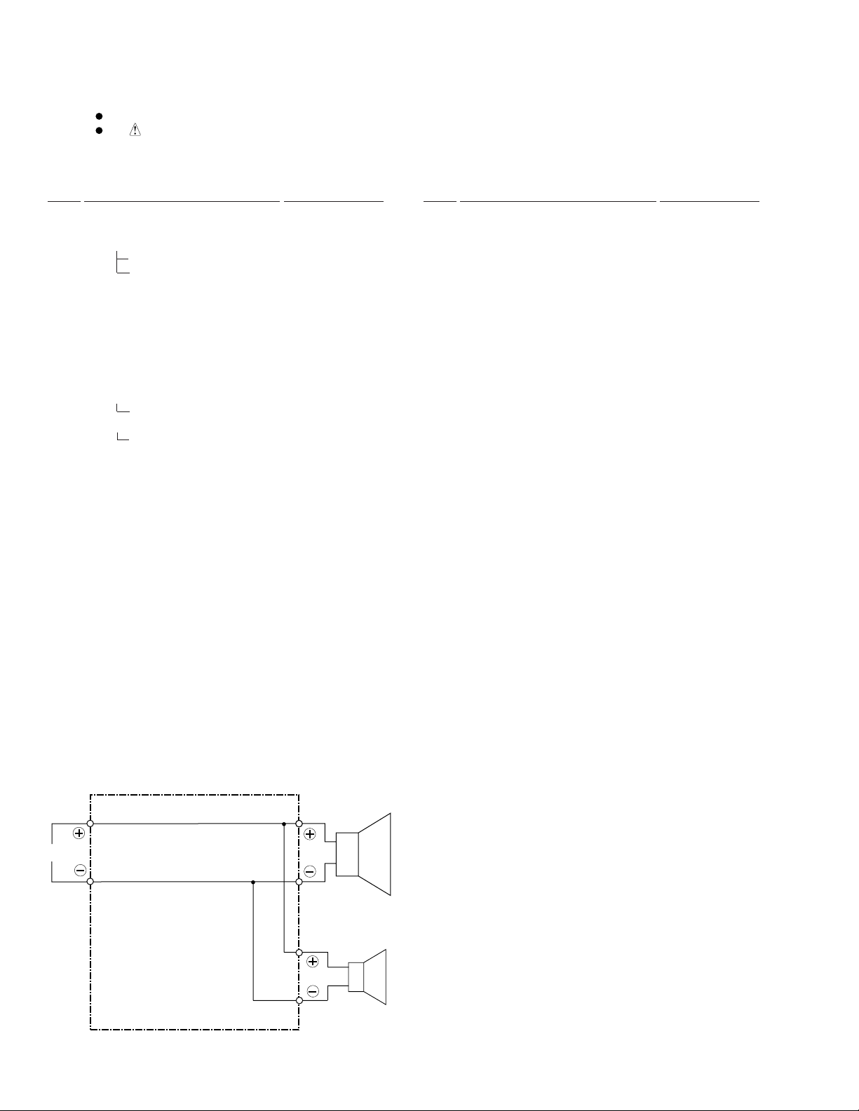
SCHEMATIC DIAGRAM
Connection Cord (SDD1271)
Transparency with blue line
I N
Transparency
Woofer
Red
Tweeter
White
2
Page 3
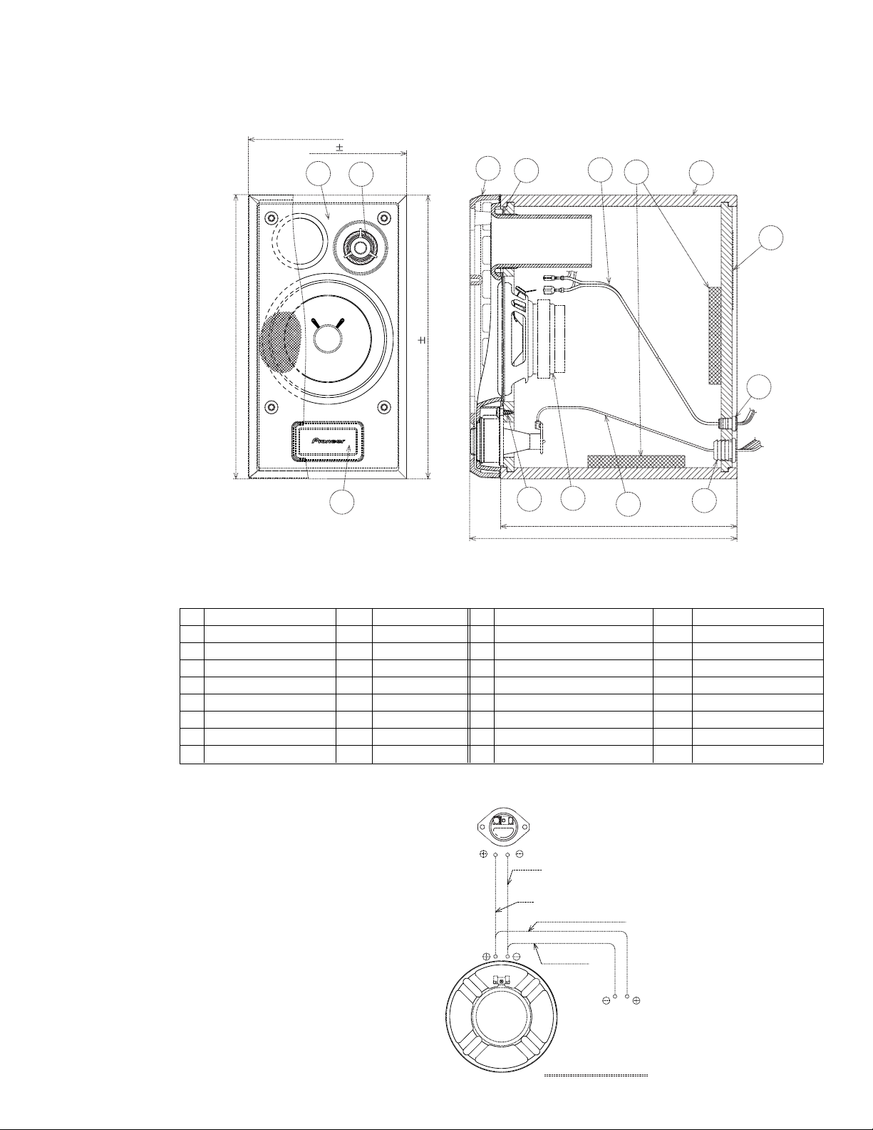
PRODUCT APPEARANCE
(131)
130 0.5
25
S-C3-S-LR
4
7
15
12
3
8
(234.5)
234 0.5
6
Part name Part name Num.Num.
1
SPEAKER
2
SPEAKER
3
CABINET
4
GRILLE
5
COSMETIC BAFFLE
6
LED BOX ASSY
71
PACKING
8
MODEL LABEL
Remarks Remarks
1
WOOFER
1
TWEETER
1
1
1
1
1
No.No.
9
10
14
15
16
11
SCREW
SCREW
SCREW
ACOUSTIC ABSORBENT
CORD STOPPER
CORD STOPPER
CONECTION CORD
CONECTION CORD
1
16
195±0.5
(220)
13
14
2
M4x12(Tw.)
4
M4x12(Wf.)
511
M4x12(Cos.BF&LED)
212
113
1
1
( For SP )
1
( For LED )
WOOFER
TWEETER
WHITE
RED
TRANSPARENCY WITH BLUE LINE
TRANSPARENCY
INPUT
WIRING DIAGRAM
3
Page 4

S-C3-S-LR
7 LED BOX ASSY
EXPLODED VIEW and PARTS LIST
NOTES:
Parts marked by "NSP" are generally unavailable because they are not in our Master Spare Parts List.
The mark found on some component parts indicates the importance of the safety factor of the part.
Therefore, when replacing, be sure to use parts of identical designation.
Screws adjacent to mark on product are used for disassembly.
7
7
6
5
1
LED BOX ASSY PARTS LIST
Mark No. Description Part No.
1 Lens Frame 1023070050
2 Speaker Lens 1022070050
3 Air Packing B 2032070050
4 LED Holder 2008070050
5 Air Packing A 2031070050
6 SP. LED PWB ASSY C14L279400
7 Screw BPZ30P080FMC
7
4
3
2
4
Page 5

1
234
7 SP. LED PWB ASSY
SCHEMATIC DIAGRAM
Note : When ordering service parts, be sure to refer to "EXPLODED VIEWS and PARTS LIST" or "PCB PARTS LIST"
LED401
NSTM515AS-0083
11V
S-C3-S-LR
A
STEREO
CD/MD
RECEIVER
XR-MDX717
SP.SOCKET
PWB ASSY
CN466(for Lch)
CN467(for Rch)
∗ In case of LED color mismatching between the receiver and the speaker,
these parts are changed as following :
CN001
+10V
RED
BLUE
GREEN
GND
5
4
3
2
1
R04B : Not used
R006 : 270Ω
R007
R003
10
100R001
100R002
100
R008 47K
C4 0.01
D004
C2 0.01
C3 0.01
MTZJ11B
D001 5.1V
2SC2001(L)
C1 0.01
Q001
R004 330
MTZJ5.1B
R B G
R04A 330
Q002
2SC2001(L)
∗
R05A 390
R04B 330
D002 5.1V
MTZJ5.1B
D003 5.1V
Q003
2SC2001(L)
R005 390
R06A 390
∗
MTZJ5.1B
B
R006 390
C
DIAGNOSIS
Confirmation of Single Display of LED
1. DC+10V is impressed for 1 pin (GND) and 5 pin (+10V) of the CN001.
2. GREEN single display: +5V is impressed to the CN001 2 pin.
3. BLUE single display: +5V is impressed to the CN001 3 pin.
4. RED single display: +5V is impressed to the CN001 4 pin.
Attention When Diagnosing
• Handle LEDs carefully because it is weak to static electricity.
• Do not impress +5V to each terminal (2, 3, and 4 pins) at the same time.
• The LED might be destroyed when impressing at the same time.
• When the LED is destroyed partially, brightness falls.(It is incomprehensible in single color.)
1
2
3
D
5
4
Page 6

1
S-C3-S-LR
PCB CONNECTION DIAGRAM
NOTE FOR PCB DIAGRAMS:
A
1. Part numbers in PCB diagrams match those in the schematic
diagrams.
2. A comparison between the main parts of PCB and schematic
diagrams is shown below.
Symbol in PCB
Diagrams
BCE
BCE
DGS
Symbol in Schematic
Diagrams
BCE
BCEBCE
DGSDGS
BCE
Part Name
Transistor
Transistor
with resistor
Field effect
transistor
23
TERMINAL LAYOUT for LED401
Red Cathode
Common Anode
Blue Cathode
Green Cathode
RED
COM
BLUE
GRN
4
Resistor array
When exchanging, note the wiring for the terminal.
B
3. The parts mounted on this PCB include all necessary parts
for several destination.
For further information for respective destinations, be sure
to check with the schematic diagram.
4. Viewpoint of PCB diagrams
Connector
Capacitor
3-terminal
regulator
SIDE A
STEREO CD/MD RECEIVER
XR-MDX717
SP.SOCKET PWB ASSY
P.C.Board Chip Part
SIDE B
CN466 ( for Lch )
CN467 ( for Rch )
SIDE A
C
R04AR004
SP. LED PWB ASSY
+10V
RB
G
GND
C2
R04B
Q001
C4
R05A
R005
C3
Q002
D
R002
C1
R001
D002
RED
COM
J001
D001
LED401
D003
D004
BLUE
GRN
R008
R007
4148279400
SP LED PWB
Q002
6
1234
CN001
R003
Q003
R006
R06A
Q003LED401Q001
Page 7

PCB PARTS LIST
S-C3-S-LR
NOTES:
Parts marked by "NSP" are generally unavailable because they are not in our Master Spare Parts List.
The mark found on some component parts indicates the importance of the safety factor of the part.
Therefore, when replacing, be sure to use parts of identical designation.
When ordering resistors, first convert resistance values into code form as shown in the following examples.
Ex.1 When there are 2 effective digits (any digit apart from 0), such as 560 ohm and 47k ohm (tolerance is shown by J=5%,
and K=10%).
560
47k
0.5
1
Ex.2 When there are 3 effective digits (such as in high precision metal film resistors).
5.62k RN1/4PC F562 x 10
56 x 10
47 x 103
R50
1R0
1
561
473
1
5621
SP. LED PWB ASSY
Mark No. Description Part No.
SEMICONDUCTORS
Q001 - Q003 2SC2001(L)
D001 - D003 MTZJ5.1B
D004 MTZJ11B
LED401 NSTM515AS-0083
CAPACITORS
C1 - C4 (0.01 µF) CKPUYF103Z25
RD1/4PU J
RD1/4PU J
RN2H K
RS1P K
561
473
R50
1R0
5621
RESISTORS
R001 - R003 (100 Ω) RD1/4PU101J
R004, R04A, R04B (330 Ω) RD1/4PU331J
R005, R006 (390 Ω) RD1/4PU391J
R05A, R06A (390 Ω) RD1/4PU391J
R007 (10 Ω) RD1/4PU100J
R008 (47 Ω) RD1/4PU470J
OTHERS
CN001 FFC 5P SIDE BASE(2.0) 4490501005
7
 Loading...