

Page 1

Speaker System
Enceinte acoustique
Lautsprechersystem
Sistema di diffusori
Luidsprekersysteem
Sistema de altavoces
PDP-S41
Operating Instructions
Mode d’emploi
Bedienungsanleitung
Istruzioni per l’uso
Gebruiksaanwijzing
Manual de instrucciones
Page 2
English
Thank you for buying this Pioneer product.
Please read through these operating instructions before using
your speaker system so you will know how to make the
most of its performance. After you have finished reading the
instructions, put them away in a safe place for future
reference.
WARNING: Handling the cords associated with
accessories sold with the product will expose you to
chemicals listed on proposition 65 known to the
State of California and other governmental entities
to cause cancer and birth defect or other
reproductive harm.
Wash hands after handling
CAUTION
About compatibility
This product is designed exclusively for use with the Pioneer
Plasma Display. For more information on compatibility, please
consult with your nearest Pioneer authorized dealer or service
center.
About installation and setting
• If you want to move the Plasma Display unit, make sure
that you remove the speaker first. In addition, do not move
the display holding on to the mounting fittings. This can
result in injury or damage to the unit.
• This speaker is wide, and may become unstable when
installed by a one person alone. This may result in injury
or product damage. Therefore, at least two people must
assemble and install them.
• When installing the speaker, do not use any screws other
than those supplied, otherwise the speaker may come
off from the main unit and fall over.
• When installing the speaker, tighten the screws firmly.
• Please handle the speaker with sufficient care, as the
grille net and the cabinet can become damaged or broken
when they are subjected to strong external impacts.
• Placing a CRT computer screen or CRT monitor near to
the speaker may result in interference or color distortion.
If this happens, distance the monitor from the speaker.
About the input
• In order to prevent damage to the speaker system
resulting from input overload, please observe the
following precautions:
• Do not use the speaker with anything other than the
specified Pioneer Plasma Display. Doing so may result in
damage or fire.
• Be sure to turn the connected devices off and remove
the power cord from the wall outlet beforehand when
changing the connection or installation method.
• When using a tone control function to greatly emphasize
treble sounds, do not use excessive amplifier volume.
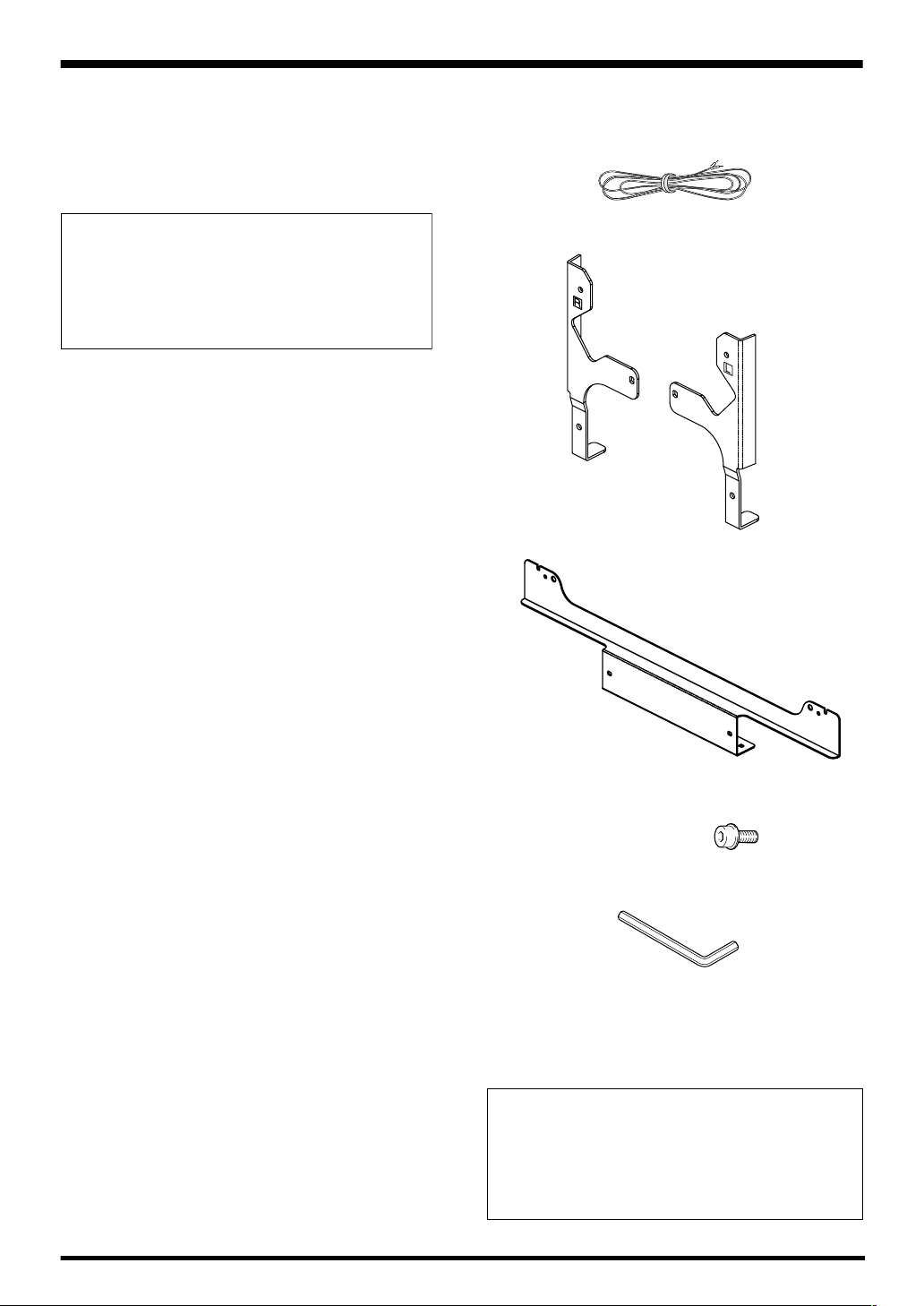
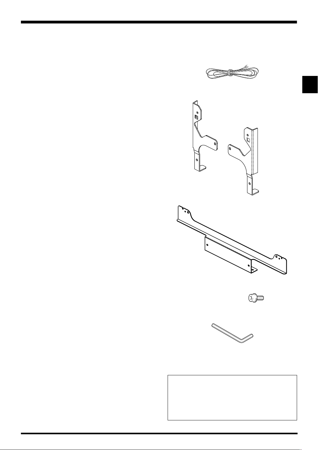
CHECKING THE ACCESSORIES
• Speaker Cable × 2
• Speaker Mounting Fittings
Bracket, for Right and Left Sides
Bracket for Center
• Speaker Mounting Screw
(M5 × 10 mm : Black) × 12
• Hexagonal wrench
(Opposite side 4 mm for M5 use) x 1
• Operating Instructions
Installation
• Consult your dealer if you encounter any difficulties
with this installation.
• Pioneer is not liable for any damage resulting from
improper installation, improper use, modification, or
natural disasters.
2
Page 3

Plasma Display with the speaker installed
Speaker
mounting
screw
(M5 x 10 mm)
English
Speaker mounting
screw (M5 x 10 mm)
English
Speaker
mounting screw
(M5 x 10 mm)
Speaker mounting fitting
(right side)
Speaker
Speaker cable
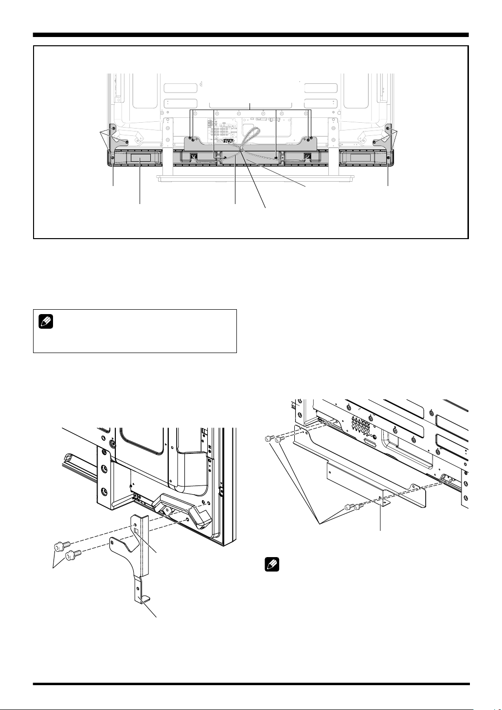
INSTALLATION ON THE PLASMA
DISPLAY
Perform installation according to the following steps 1 to 4.
NOTE:
Before attaching the speaker, please attach the table top
stand to the Plasma Display unit.
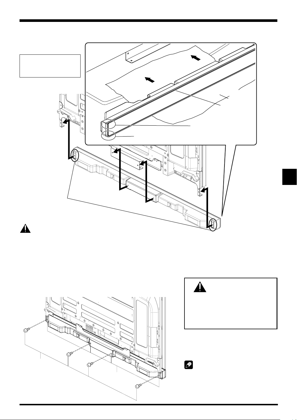
1. Attach the speaker mounting fittings to the
rear of the Plasma Display.
• Attach the fittings for right and left sides to the bottom
right and left on the rear panel of the Plasma Display using
the supplied screws.
• Tighten the two screws in the order 1 followed by 2.
Speaker mounting
fitting (center)
Bead Band
(Accessories of the Plasma Display)
Speaker mounting
fitting (left side)
2. Attach the center fitting to the lower center
on the rear panel of the Plasma Display.
• Attach the center fitting to the lower center on the rear
panel of the Plasma Display using the four supplied
screws.
• Tighten the four screws in the order 1, 2, 3, 4 as shown
in the drawing.
• When fitting the screws, place screws 1 and 2 through
the holes in the center fitting, and align screws 3 and 4
with the cutaway slots in the center fitting.
4
2
1
2
Speaker mounting
screw (M5 x 10 mm)
Label “L” is
affixed to the left
side fitting.
(Similarly, label
“R” is
affixed to the
right side fitting.)
Speaker mounting fitting for the
left side
(the fitting method is the same
as the fitting for the right side)
1
3
Speaker mounting
screw (M5 x 10 mm)
NOTE:
• See page 6 for speaker mounting procedures when using
the hung on wall unit.
Speaker mounting fitting for
center
3
Page 4
English
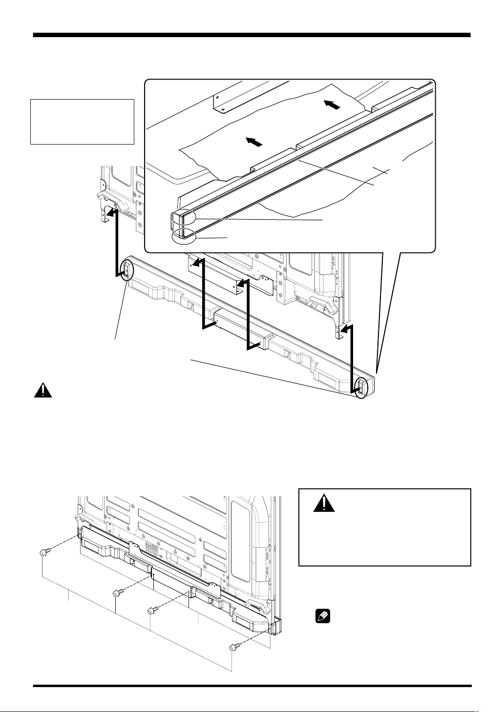
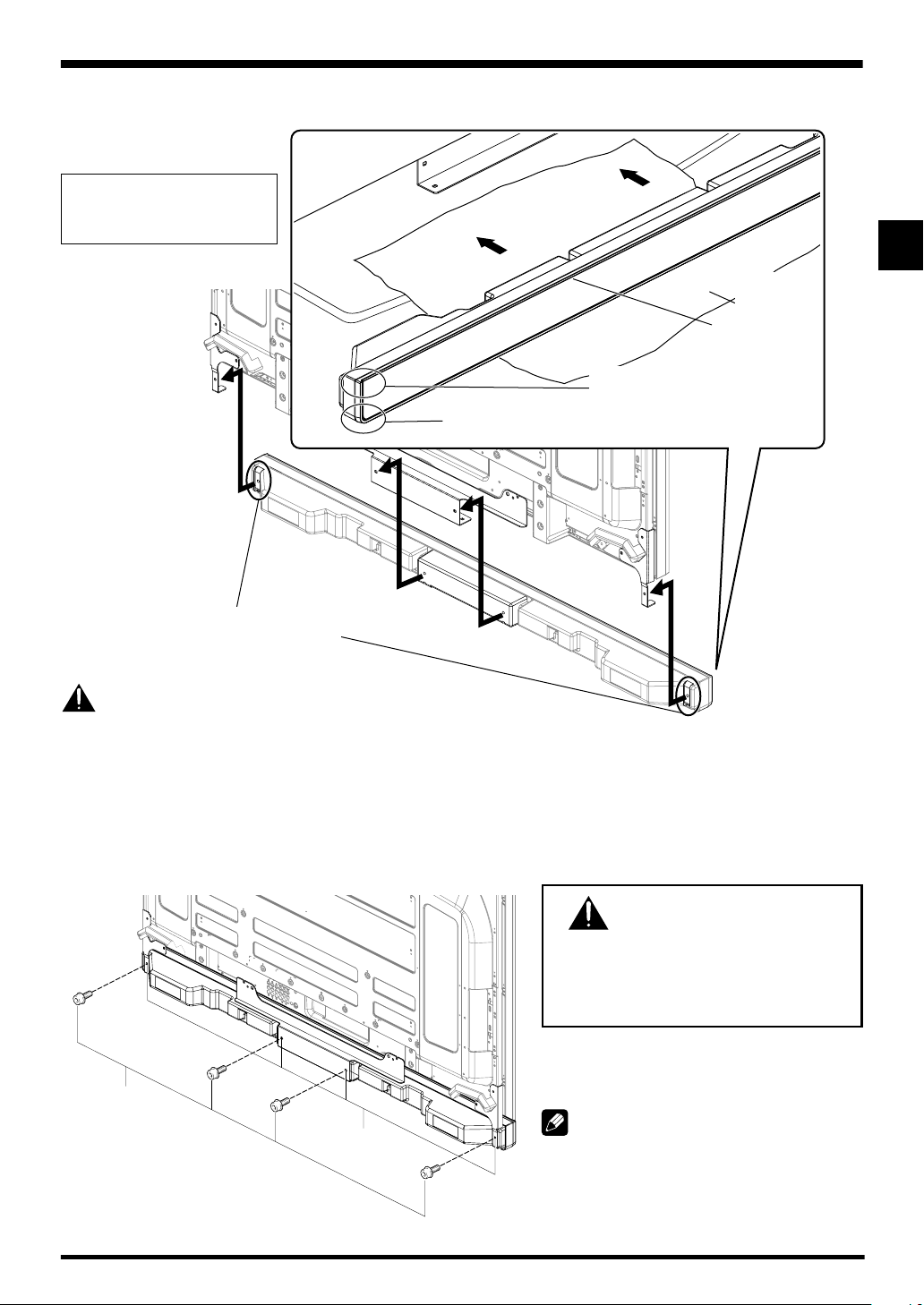
3. Fit the speaker to the mounting fittings in the correct direction.
• Be sure not to mount the speaker upside down.
For illustrative purposes,
the table top stand is not
presented here.
The upper side of the speaker
does not have a round corner.
The bottom side of the speaker has a round corner
when viewed from the front side of the Plasma Display.
Protective
wrapping
Front side of
the speaker
Insert the speaker
mounting fittings into the
grooves at the rear of the
speaker.
Caution
• To avoid any damage to the speaker and/or table top stand from striking against each other, fit the speaker to the mounting
fittings while confirming their locations. As you may easily strike the stand, use the protective wrapping in which the speaker
was wrapped between the speaker and stand.
• When the speaker mounting fittings do not fit the grooves at the rear of the speaker, adjust the speaker mounting fittings
angle.
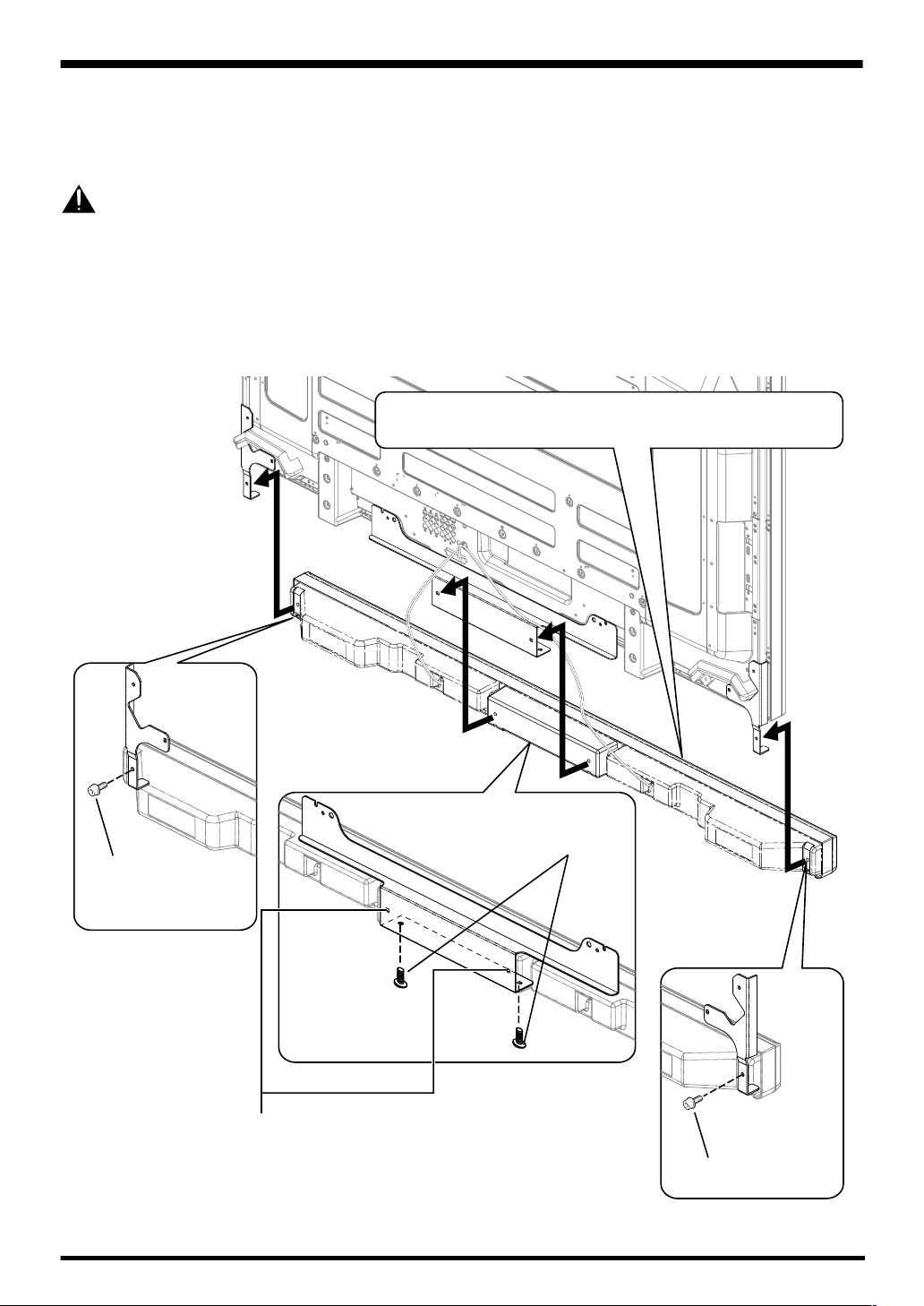
4. Fix the speaker mounting fittings and the speaker with the supplied screws.
• Fix the center part of the speaker first with the supplied screws, then fix the right and left sides alike.
• Tighten the four screws in the order 1, 2, 3, 4 as shown in the drawing.
CAUTION
If you want to move the Plasma Display unit,
make sure that you remove the speaker first.
4
Speaker
mounting screw
(M5 x 10 mm)
2
1
Screw hole
3
In addition, do not move the display holding on
to the mounting fittings. This can result in injury
or damage to the unit.
The screw hole at the bottom surface of the
speaker mounting fitting is used when the
Plasma Display is installed on the wall. It is
not used when installed with the stand.
NOTE:
If after attaching the speaker its position
needs to be adjusted horizontally or vertically,
first loosen the speaker mounting screws,
reposition and then tighten the screws again
at the appropriate position.
4
Page 5

English
5. Connect the supplied speaker
cables to the back of Plasma
Display.
• Connect the cables correctly with respect to the
polarity of the Plasma Display and the speaker
terminals, that is, cable to terminals and
cable to terminals. To do so, connect the
cable with the gray line to the terminals and
the white cable to the terminals.
Gray line
Red
White
Black
Gray line
Red
Speaker terminal
Black
6. Connect the other end
of the speaker cables
Gray lineWhite
Red
• Press the lever and insert the end of the
cable.
• When you release the lever, it clamps onto
the speaker cable.
to the speaker.
• Connect the cables correctly with
respect to the polarity of the Plasma
Display and the speaker terminals,
that is, cable to terminals and
cable to terminals. To do so,
connect the cable with the gray line
to the terminals and the white
cable to the terminals.
Lever
English
Speaker terminal Speaker cable Speaker terminal
Caution
• Be sure to turn the connected devices off and remove
the power cord from the wall outlet beforehand when
changing the connection or installation method.
• If you insert the speaker cable too far so that the insulation
is touching the speaker terminal, you may not get any
sound. Please insert it with showing the copper wire.
• Check if the end of the speaker cables are securely
connected to the terminals by slightly tugging on the cable
after making connections. Loose connections may result
in sound dropouts or noise.
• If there is a short in the and cables caused by an
exposed lead wire, excessive load may be applied to the
Plasma Display, resulting in interrupted operation or
malfunction.
• Incorrect connections of the speaker cable to the right or
left of the Plasma Display terminals with respect to the
polarity may result in insufficient stereo sound effects,
delivering poor bass sounds or unstable sound image.
• Bundle the code without pulling the cord.
5
Page 6
English
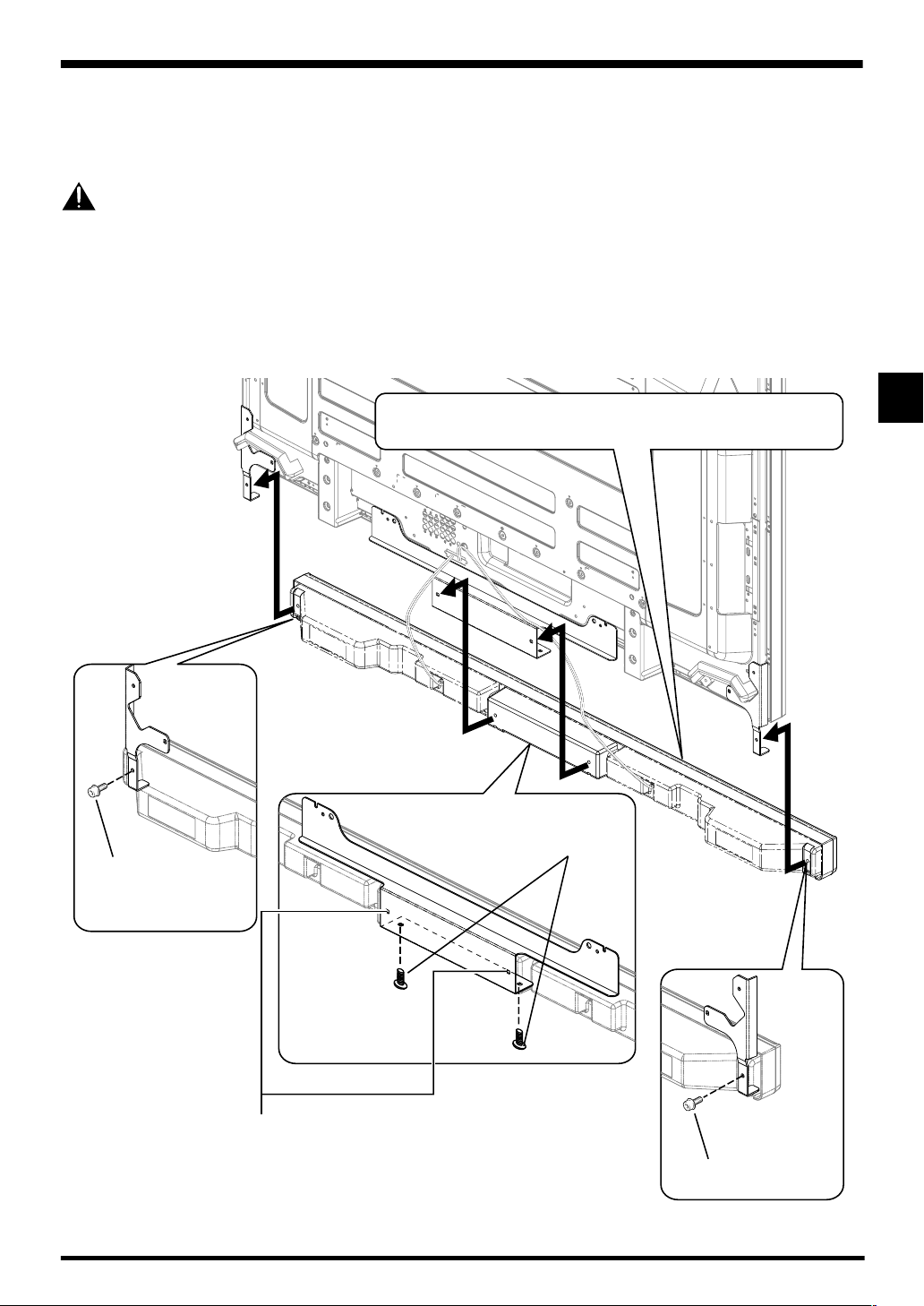
When using the hung on wall unit:
First install the Plasma Display on the wall with only the speaker mounting fittings and speaker cable attached to the display,
and then attach the speaker. (See page 3)
To facilitate attachment of wiring, it is recommended to complete the wiring on the sides of the Plasma Display before
mounting speaker to the display.
Caution
Be careful about the speaker mounting fittings when installing or connecting. This may result in injury.
3. Connect the supplied speaker cables to the back of the Plasma Display.
4. Place the Plasma Display on the mounting fittings of the hung on wall unit.
• For details, refer to the instruction manual supplied with the hung on wall unit.
5. Connect the other end of the speaker cables to the speaker.
6. Place the speaker on the speaker mounting
fittings in the correct direction.
4
Speaker mounting screw
Speaker mounting
screw (M5 x 10 mm)
2
When using the hung on
wall unit, do not use these
holes.
(M5 x 10 mm)
1
7. Tighten using the supplied screws (4 locations).
• Tighten the four screws in the order 1, 2, 3, 4 as shown in the drawing.
6
3
Speaker mounting screw
(M5 x 10 mm)
Page 7
English
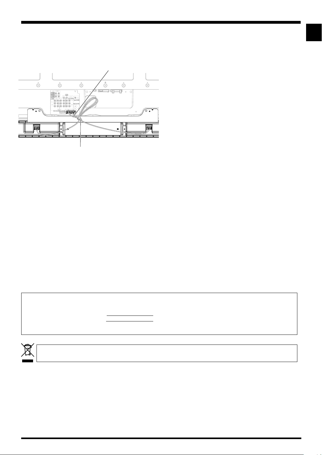
HOW TO ROUTE CABLES
Bead bands are included with the Plasma Display.
For tidying up your speaker cables, use the bead bands when
needed.
Speaker cable
Rear of Display
Bead Band
CABINET MAINTENANCE
• Use a polishing cloth or dry cloth to wipe off dust and
dirt.
• When the cabinet is very dirty, wipe with a soft cloth
moistened with water-diluted cleanser; then wipe again
with a dry cloth. Do not use furniture wax or cleaners.
They may damage the surface of the cabinet.
• Never use thinner, benzine, insecticide sprays and other
chemicals on or near the cabinets, since these will corrode
the surfaces.
• When a chemical cloth is used, read the cautions for the
chemical cloth carefully.
SPECIFICATIONS
Cabinet: Bass-reflex type
Used speaker (two-way system):
Woofer (for low tones)..........4.8 cm × 13 cm cone type
Tweeter (for high tones) ........... 2.5 cm semidome type
Nominal impedance ..................................................... 8 Ω
Frequency Range................................ 66 Hz to 30 000 Hz
Sensitivity (1 m, 1 W) ...............................................80 dB
Permissible input :
Max. input .............................................................. 13 W
Rated input .............................................................. 4 W
Crossover frequency ................................................ 3 kHz
External Dimensions
..................... 1 470 mm (W) × 87 mm (H) × 115 mm (D)
Weight ..................................................................... 3.8 kg
Accessory parts
............................................................ Speaker cable × 2
............................................................................. Bracket
Right × 1
Left × 1
Center × 1
.............................................. Screw (M5 × 10 mm) × 12
..................................................... Hexagonal wrench x 1
.............................................. Operating Instructions × 1
NOTE:
Specifications and design subject to possible modification
without notice, due to improvements.
English
IMPORTANT NOTICE – RECORD THE MODEL NUMBER AND SERIAL NUMBERS OF THIS EQUIPMENT BELOW.
THE NUMBERS ARE ON THE REAR.
MODEL NO.
SERIAL NO.
KEEP THESE NUMBERS FOR FUTURE USE.
If you want to dispose this product, do not mix it with general household waste. There is a separate collection system for used
electronic products in accordance with legislation that requires proper treatment, recovery and recycling.
Private households in the 25 member states of the EU, in Switzerland and Norway may return their used electronic products free of charge to
designated collection facilities or to a retailer (if you purchase a similar new one).
For countries not mentioned above, please contact your local authorities for the correct method of disposal.
By doing so you will ensure that your disposed product undergoes the necessary treatment, recovery and recycling and thus prevent potential
negative effects on the environment and human health.
Published by Pioneer Corporation.
Copyright © 2006 Pioneer Corporation.
All rights reserved.
D1-4-2-6-2_En
K058_En
7
Page 8

English
8
Page 9
Français
Merci pour votre achat de cet appareil Pioneer.
Veuillez lire attentivement la totalite de ce mode d’emploi
avant d’utiliser vos enceintes acoustiques de façon à pouvoir
en tirer le meilleur profit. Après lecture complète du livret
d’instructions de fonctionnement, le ranger dans un endroit
sûr afin de pouvoir vous y reporter facilement en cas de
besoin lors de l’utilisation des l’enceintes acoustiques.
ATTENTION
À propos de la compatibilité
Ce produit est conçu exclusivement pour l’utilisation avec
un Écran Plasma Pioneer. Pour de plus amples informations
sur la compatibilité, veuillez vous adresser au distributeur ou
au centre de service Pioneer agréé le plus proche.
À propos de l’installation et des réglages
• Si vous déplacez l’Écran Plasma, veillez à retirer d’abord
les enceintes. De plus, ne déplacez pas l’écran en le tenant
par ses ferrures de fixation, car vous pourriez vous blesser
ou endommager l’appareil.
• Cette enceinte est large et elle risque d’être déstabilisée
si elle est installée par une seule personne. Ce qui peut
entraîner des blessures ou des dégâts à l’appareil. Par
conséquent, il est conseillé d’agir à deux pour assembler
et installer les éléments.
• À l’installation des enceintes, utilisez uniquement les vis
fournies, car d’autres pourraient se détacher de l’unité
principale et entraîner la chute des enceintes.
• A l’installation des enceintes, serrez les vis à fond.
• Manipuler les enceintes avec suffisamment de soin, car
autrement, l’enjoliveur frontal et le coffret risqueraient
d’être endommagés ou hors d’usage en les soumettant
à des chocs externes exagérés.
• La présence d’un écran d’ordinateur ou d’un moniteur à
tube cathodique près des enceintes peut provoquer des
interférences et une distorsion des couleurs. Si c’est le
cas, éloignez l’écran par rapport aux enceintes.
VÉRIFICATION DES
ACCESSOIRES
• Câbles d’enceinte × 2
• Supports pour montage des enceintes
Support, pour côtés gauche et droit
Français
Support central
À propos de l’entrée des signaux
• Afin d’éviter d’endommager les enceintes acoustiques,
suite à une surcharge à l’entrée, veuillez observer les
précautions suivantes:
• N’utilisez jamais les enceintes avec un appareil autre que
l’Écran Plasma Pioneer spécifié. Faute de quoi, des dégâts,
voire un incendie pourraient en résulter.
• Prenez soin de mettre hors tension les appareils raccordés
et de débrancher le cordon d’alimentation au niveau de la
prise secteur avant de changer les connexions ou la
méthode d’installation.
• Si vous utilisez une fonction de contrôle des tonalités pour
accentuer fortement les aigus, n’élevez pas excessivement
le volume sonore.
• Vis de montage d’enceintes
(M5 × 10 mm : Noires) × 12
• Clé hexagonale
(Taille en diagonale 4 mm pour utilisation M5) x 1
• Mode d’emploi
Installation
• En cas de difficultés, veuillez consulter votre revendeur.
• Pioneer ne saurait être tenu responsable d’aucun
dommage résultant d’une installation ou d’une
utilisation incorrecte de ce produit, de sa modification
ou encore de catastrophes naturelles.
9
Page 10
Français
Écran Plasma doté de ses enceintes
Vis de montage d’enceintes
(M5 x 10 mm)
Vis de montage
d’enceintes
(M5 x 10 mm)
Ferrure de montage
d’enceintes (côté droit)
Enceintes
Câble d’enceinte
Collier à grains
(Accessoire pour Écran Plasma)
INSTALLATION SUR L’ÉCRAN PLASMA
Effectuez l’installation comme décrit aux étapes 1 à 4 cidessous.
REMARQUE:
Avant de monter l’enceinte, fixez le support du dessus
de table sur l’Écran Plasma.
1. Fixez les ferrures de montage d’enceintes sur
l’arrière de l’Écran Plasma.
• Fixez les ferrures pour les côtés gauche et droit sur la
partie inférieure gauche et droite à l’arrière de l’Écran
Plasma en vous servant des vis fournies.
• Serrez les deux vis dans l’ordre suivant : 1 puis 2.
2. Fixez la ferrure centrale dans la partie
• Fixez la ferrure centrale dans le bas au centre sur le
• Serrez les quatre vis dans l’ordre : 1, 2, 3, 4, comme
• Lors de la fixation des vis, placez les vis 1 et 2 par les
Vis de montage
d’enceintes
(M5 x 10 mm)
Ferrure de montage
d’enceintes (centre)
Ferrure de montage
d’enceintes (côté gauche)
centrale inférieure sur le panneau arrière de
l’Écran Plasma.
panneau avant de l’Écran Plasma au moyen des quatre
vis fournies.
indiqué sur le dessin.
trous dans la ferrure centrale et alignez les vis 3 et 4
avec les encoches découpées dans la ferrure centrale.
1
2
Vis de montage
d’enceintes
(M5 x 10 mm)
Ferrure de montage d’enceinte pour le côté
gauche (La même méthode de montage
s’applique au côté droit).
10
Une étiquette “L”
est fixée sur la ferrure
du côté gauche. (De
même, une étiquette
“R” est fixée sur celle
du côté droit.)
4
2
1
3
Vis de montage d’enceintes
(M5 x 10 mm)
REMARQUE:
• Reportez-vous à la page 13 pour la méthode de fixation
des enceintes lorsque l’Écran est suspendu sur une paroi.
Ferrure de montage
d’enceinte pour le centre
Page 11
3. Fixez les enceintes sur les ferrures de montage dans la bonne direction.
• Prenez soin de ne pas monter les enceintes à l’envers.
Pour des raisons
d’illustration, le socle de
table n’est pas présenté ici.
Emballage
de protection
Face avant
des enceintes
Le côté supérieur des enceintes
n’a pas de coin arrondi.
Le côté inférieur des enceintes a un coin arrondi quand
on les regarde depuis l’avant de l’Écran Plasma.
Français
Français
Insérez les ferrures de montage
d’enceintes dans les rainures à
l’arrière des enceintes.
Attention
• Pour éviter tout dégât aux enceintes et/ou au socle de table, provoqué par des chocs mutuels, fixez les enceintes sur les
ferrures de montage en observant bien leurs emplacements. Comme le socle risque d’être cogné, servez-vous de l’emballage
de protection dans lequel les enceintes étaient enveloppées pour éviter les coups entre les enceintes et le socle.
• Si les ferrures de montage d’enceintes ne correspondent pas aux rainures à l’arrière des enceintes, ajustez l’angle des
ferrures.
4. Fixez les ferrures de montage d’enceintes et les enceintes au moyen des vis fournies.
• Fixez d’abord la partie centrale de l’enceinte au moyen des vis fournies, puis fixez les côtés gauche et droit de la même façon.
• Serrez les quatre vis dans l’ordre : 1, 2, 3, 4, comme indiqué sur le dessin.
ATTENTION
Si vous voulez déplacer l’Écran Plasma, veillez à
enlever d’abord les enceintes.
4
Vis de montage
d’enceintes
(M5 x 10 mm)
2
1
Trou de vis
3
De plus, ne déplacez pas l’écran en le tenant par
les support de montage. Vous pourriez vous
blesser ou endommager l’écran.
Le trou de vis dans la surface inférieure de la
ferrure de montage d’enceintes s’emploie quand
l’Écran Plasma est installé sur une paroi. Il n’est
pas utilisé lors d’une installation sur socle.
REMARQUE:
Si, après avoir installé les enceintes, leur position doit
être ajustée dans le sens horizontal ou vertical,
desserrez d’abord les vis de fixation d’enceintes,
modifiez la position et serrez à nouveau les vis à
l’endroit adéquat.
11
Page 12

Français
5. Branchez les câbles d’enceintes
fournis sur l’arrière de l’Écran
Plasma.
• Connectez les câbles correctement par rapport
à la polarité des bornes de l’écran plasma et des
enceintes, c’est-à-dire, câbles aux bornes
et câbles aux bornes . Pour ce faire,
connectez le câble portant le trait gris aux bornes
et le câble blanc aux bornes .
Trait gris Trait gris
Rouge
Blanc
Noir
Rouge
Borne d’enceinte
Noir
6. Branchez l’autre bout
des câbles d’enceintes
Trait grisBlanc
Rouge
• Appuyez sur le levier et insérez l’extrémité
du câble.
• Quand vous relâchez le levier, la borne
serre sur le câble d’enceinte.
sur les enceintes.
• Connectez les câbles correctement
par rapport à la polarité des bornes
de l’écran plasma et des enceintes,
c’est-à-dire, câbles aux bornes
et câbles aux bornes . Pour ce
faire, connectez le câble portant le
trait gris aux bornes et le câble
blanc aux bornes .
Levier
Borne d’enceinte
Attention
• Prenez soin de mettre hors tension les appareils raccordés
et de débrancher le cordon d’alimentation au niveau de la
prise secteur avant de changer les connexions ou la
méthode d’installation.
• Si vous insérez le câble d’enceintes trop loin,
au point que l’isolant touche la borne
d’enceinte, il est possible qu’aucun son ne
soit obtenu. Insérez le câble en laissant le
fil de cuivre visible.
• Vérifiez si le bout des câbles d’enceintes
est bien immobilisé dans les bornes en tirant
légè rement sur le câble après son
branchement. Des connexions relâchées
risquent de provoquer des pertes de son
ou des parasites.
Câble d’enceinte
Borne d’enceinte
• Si un court-circuit s’est établi entre les câbles et à
cause de fils dénudés, une charge excessive risque d’être
appliquée à l’Écran Plasma, ce qui provoquerait une
interruption ou un dysfonctionnement.
• Des branchements incorrects, ne respectant pas les
polarités des câbles d’enceintes sur les bornes gauche
et droit de l’Écran Plasma, dégraderont les effets stéréo,
les graves laisseront à désirer et l’image sonore sera
instable.
• Regroupez les cordons sans les étirer.
12
Page 13

Français
À l’emploi de l’unité de montage sur paroi :
Installez d’abord l’Écran Plasma sur la paroi uniquement avec les ferrures de montage d’enceintes et les câbles d’enceintes
rattachés sur l’écran. Fixez ensuite les enceintes. (Reportez-vous à la page 10.)
Pour faciliter la fixation du câblage, il est conseillé d’achever le câblage sur les côtés de l’Écran Plasma avant de monter
l’enceinte sur l’écran.
Attention
Pour ne pas vous blesser, agissez avec prudence lors de l’installation des ferrures de montage d’enceintes et lors des
branchements.
3. Raccordez les câbles d’enceintes fournis sur l’arrière de l’Écran Plasma.
4. Placez l’Écran Plasma sur les ferrures de montage de l’unité de montage sur paroi.
• Pour plus de détails, reportez-vous au mode d’emploi fourni avec l’unité de montage sur paroi.
5. Branchez l’autre bout des câbles d’enceintes sur les enceintes.
6. Placez les enceintes dans la bonne direction
sur les ferrures de montage d’enceintes.
Français
4
Vis de montage
d’enceintes (M5 x 10 mm)
Vis de montage
d’enceintes
(M5 x 10 mm)
2
1
A l’emploi de l'unité suspendue à
un mur, n’utilisez pas ces trous.
7. Immobilisez au moyen des vis fournies (4 endroits).
• Serrez les quatre vis dans l’ordre : 1, 2, 3, 4, comme indiqué sur le dessin.
3
Vis de montage
d’enceintes (M5 x 10 mm)
13
Page 14

Français
COMMENT FAIRE CHEMINER
LES CÂBLES
Des colliers à oeil sont fournis avec l’Écran Plasma.
Utilisez ces colliers à oeil comme nécessaire pour ranger les
câbles d’enceinte.
Câble d’enceinte
Dos de l’écran
Collier à grains
ENTRETIEN DU COFFRET
• Utiliser un chiffon à polir ou un chiffon sec pour essuyer
la poussière et éliminer les salissures.
• Si le coffret est très sale, le frotter avec un chiffon doux
imbibé de liquide à nettoyer dilué d’eau. Ensuite, essuyer
à nouveau avec un chiffon sec. Ne pas utiliser de cire à
meuble ou de produits de nettoyage corrosifs. Ils
risqueraient d’endommager la surface du coffret.
• Ne jamais utiliser non plus de diluant, de benzine,
d’insecticides en vaporisateur et autres produits
chimiques sur le coffret ou à proximité, car ils risquent
de corroder les surfaces.
• Si l’on utilise un chiffon chimique, lire et observer
attentivement les précautions à prendre pour son usage
adéquat.
SPECIFICATIONS
Coffret : Type bass-reflex
Haut-parleurs utilisés (système à double voie) :
Haut-parleur de graves
....................................... Type à cône de 4,8 cm × 13 cm
Haut-parleur d’aigus .......... Type à semi-dôme de 2,5 cm
Impédance nominale .....................................................8 Ω
Plage de fréquences .............................. 66 Hz à 30 000 Hz
Sensibilité (1 m, 1 W) ................................................ 80 dB
Entrée admissible :
Entrée max. .............................................................. 13 W
Entrée nominale ........................................................ 4 W
Fréquence de recouvrement ..................................... 3 kHz
Encombrement
........................ 1 470 mm (L) × 87 mm (H) × 115 mm (P)
Poids ......................................................................... 3,8 kg
Pièces accessoires
....................................................... Câbles d’enceinte × 2
............................................................................ Supports
Droit × 1
Gauche × 1
Central × 1
..................................................... Vis (M5 × 10 mm) × 12
............................................................ Clé hexagonale x 1
............................................................ Mode d’emploi × 1
REMARQUE:
Les spécifications et la finition sont susceptibles d’être
modifiées sans préavis en vue de l’amélioration.
AVIS IMPORTANT
– VEUILLEZ REPORTER CI-DESSOUS LES NUMEROS DE MODELE ET DE SERIE DE L’EQUIPEMENT.
CES NUMEROS APPARAISSENT A L’ARRIERE.
Nº MODELE :
Nº SERIE :
VEUILLEZ CONSERVER CES NUMEROS EN VUE DE FUTURES UTILISATIONS.
Si vous souhaitez vous débarrasser de cet appareil, ne le mettez pas à la poubelle avec vos ordures ménagères. Il existe un système de
collecte séparé pour les appareils électroniques usagés, qui doivent être récupérés, traités et recyclés conformément à la législation.
Les habitants des 25 états membres de l’UE, de Suisse et de Norvège peuvent retourner gratuitement leurs appareils électroniques usagés aux
centres de collecte agréés ou à un détaillant (si vous rachetez un appareil similaire neuf).
Dans les pays qui ne sont pas mentionnés ci-dessus, veuillez contacter les autorités locales pour savoir comment vous pouvez vous débarrasser
de vos appareils.
Vous garantirez ainsi que les appareils dont vous vous débarrassez sont correctement récupérés, traités et recyclés et préviendrez de cette façon
les impacts néfastes possibles sur l’environnement et la santé humaine.
Publication de Pioneer Corporation.
© 2006 Pioneer Corporation.
Tous droits de reproduction et de
traduction réservés.
K058_Fr
14
Page 15

Deutsch
Wir danken Ihnen dafür, dass Sie sich für ein Produkt von
Pioneer entschieden haben.
Bitte lesen Sie vor der Verwendung Ihrer Lautsprecheranlage
diese Anleitung aufmerksam durch, um die Vorzüge des
Systems optimal ausnützen zu können. Nachdem Sie die
Bedienungsanleitung durchgelesen haben, bewahren Sie sie
sorgfältig auf, um sich im Bedarfsfall jederzeit darauf beziehen
zu können.
VORSICHT
Hinweis zur Kompatibilität
Dieses Produkt ist für ausschließlichen Gebrauch mit dem
Pioneer Plasma Display vorgesehen. Weitere Informationen
zur Kompatibilität bringen Sie bitte bei Ihrem autorisierten
Pioneer-Händler oder einer Pioneer-Kundendienststelle in
Erfahrung.
Hinweise zur Installation und Einstellung
• Achten Sie vor einem Transport des Plasma-Displays an
einen anderen Ort darauf, zuerst den Lautsprecher zu
entfernen. Tragen Sie das Plasma-Display nicht an den
Lautsprecher-Befestigungsteilen, da dies Verletzungen
oder eine Beschädigung des Gerätes verursachen kann.
• Dieser Lautsprecher ist sehr breit und kann unstabil
werden, wenn er von einer einzigen Person installiert wird.
Da dies Verletzungen oder eine Beschädigung
verursachen kann, sollte die Installation grundsätzlich von
mindestens zwei Personen ausgeführt werden.
• Verwenden Sie zur Installation ausschließlich die Schrauben
im Lieferumfang. Anderenfalls kann sich der Lautsprecher
vom Plasma-Display lösen und herunterfallen.
• Achten Sie bei der Installation des Lautsprechers darauf,
die Schrauben fest anzuziehen.
• Die Lautsprecher sind vorsichtig zu behandeln, da Ziergitter
und Gehäuse durch starke Stöße und Erschütterungen
verkratzt bzw. beschädigt werden können.
• Wenn ein CRT-Computer-Monitor oder ein CRT-Monitor
in der Nähe des Lautsprechers aufgestellt wird, kann dies
Bildrauschen oder Farbstörungen verursachen. In einem
solchen Fall muss für einen größeren Abstand des
Monitors vom Lautsprecher gesorgt werden.
Hinweise zum Eingang
• Um eine Beschädigung des Lautsprechersystems durch
ein zu starkes Eingangssignal zu vermeiden, müssen die
folgenden Hinweise unbedingt beachtet werden:
• Dieser Lautsprecher ist ausschließlich zum Gebrauch mit
dem dafür vorgeschriebenen Pioneer Plasma-Display
vorgesehen. Wird der Lautsprecher in Verbindung mit
irgendeinem anderen Gerät verwendet, besteht die
Gefahr von Beschädigung und Brandausbruch.
• Achten Sie unbedingt darauf, alle angeschlossenen Geräte
auszuschalten und den Netzstecker von der
Netzsteckdose zu trennen, bevor die Anschlüsse geändert
werden oder die Installation verändert wird.
• Bei Verwendung der Klangfarbenregelungs-Funktion
eines Verstärkers zu einer starken Anhebung der Höhen
darf die Lautstärke am Verstärker nicht auf einen
übermäßig hohen Pegel eingestellt werden.
ÜBERPRÜFEN DES ZUBEHÖRS
• Lautsprecherkabel × 2
• Lautsprecher-Befestigungsteile
Halterungen, je eine für die rechte und die linke Seite
Deutsch
Halterung für Mitte
• Lautsprecher-Befestigungsschraube
(M5 × 10 mm : Schwarz) × 12
• Innensechskantschlüssel
(Gegenseite 4 mm für M5-Verwendung) x 1
• Bedienungsanleitung
Installation
• Wenn es bei dieser Installation zu Problemen kommen
sollte, wenden Sie sich bitte an Ihren Händler.
• Pioneer haftet für keinerlei Schäden, die sich auf falsche
Installation, unsachgemäßen Gebrauch, Modifikationen
oder Naturkatastrophen zurückführen lassen.
15
Page 16

Deutsch
Plasma-Display mit installiertem Lautsprecher
LautsprecherBefestigungsschraube
(M5 x 10 mm)
LautsprecherBefestigungsschraube
(M5 x 10 mm)
LautsprecherBefestigungsschraube
(M5 x 10 mm)
LautsprecherBefestigungsteil
(rechte Seite)
Lautsprecher
Lautsprecherkabel
Kugelband
(Zubehör des Plasma-Displays)
INSTALLATION AM PLASMA DISPLAY
Nehmen Sie die Installation gemäß den folgenden Schritten
1 bis 4 vor.
HINWEIS:
Bringen Sie vor der Lautsprechermontage das Tischgestell
am Plasma-Display an.
1. Bringen Sie die Lautsprecher-Befestigungsteile
an der Rückseite des Plasma-Displays an.
• Bringen Sie die Befestigungsteile für die rechte und linke
Seite mit den mitgelieferten Schrauben jeweils rechts und
links unten an der Rückseite des Plasma-Displays an.
• Ziehen Sie die beiden Schrauben in der numerischen
Reihenfolge 1 und 2 der Abbildung an.
2. Bringen Sie das mittlere Befestigungsteil in
• Bringen Sie das mittlere Befestigungsteil mit den vier
• Ziehen Sie die vier Schrauben in der numerischen
• Zum Anbringen der Schrauben stecken Sie Schraube 1
LautsprecherBefestigungsteil (Mitte)
LautsprecherBefestigungsteil
(linke Seite)
der Mitte unten an der Rückseite des PlasmaDisplays an.
mitgelieferten Schrauben in der Mitte unten an der
Rückseite des Plasma-Displays.
Reihenfolge 1, 2, 3 und 4 der Abbildung an.
und 2 durch die Löcher im mittleren Befestigungsteil,
und richten Sie Schraube 3 und 4 auf die Ausschnitte
im mittleren Befestigungsteil aus.
4
2
1
2
LautsprecherBefestigungsschraube
(M5 x 10 mm)
Lautsprecher-Befestigungsteil für linke
Seite (die Befestigung erfolgt auf gleiche
Weise wie für die linke Halterung)
16
Ein Aufkleber mit dem
Buchstaben „L“ ist an der
Halterung für die linke Seite
angebracht. (Die der Halterung für
die rechte Seite wird durch einen
Aufkleber mit dem Buchstaben
„R“ gekennzeichnet.)
1
3
LautsprecherBefestigungsschraube
(M5 x 10 mm)
HINWEIS:
• Bei Verwendung der Wandbefestigungseinheit gehen Sie
zur Installation des Lautsprechers wie auf Seite 19
beschrieben vor.
LautsprecherBefestigungsteil für Mitte
Page 17

Deutsch
3.
Bringen Sie den Lautsprecher mit der korrekten Ausrichtung an den Befestigungsteilen an.
• Achten Sie sorgfältig darauf, den Lautsprecher nicht verkehrt herum zu befestigen.
Zur besseren
Übersichtlichkeit der
Darstellung wird das
Tischgestell nicht in der
Abbildung gezeigt.
Schutzhülle
Vorderseite des
Lautsprechers
Passen Sie die
LautsprecherBefestigungsteile in die
Nuten an der Rückseite
des Lautsprechers ein.
Von der Vorderseite des Plasma-Displays aus gesehen besitzt
die Unterseite des Lautsprechers eine abgerundete Ecke.
Die Oberseite des Lautsprechers
besitzt keine abgerundete Ecke.
VORSICHT
• Um eine Beschädigung des
Lautsprechers und/oder des
Tischgestells zu vermeiden, die durch
ein Aufschlagen des Lautsprechers auf das
Tischgestell verursacht werden kann, ist die Lage
der Befestigungsteile beim Einsetzen des Lautsprechers
sorgfältig zu überprüfen. Legen Sie die Schutzhülle, in die der
Lautsprecher ursprünglich eingewickelt war, zwischen Lautsprecher
und Tischgestell, um eine Beschädigung durch Aufschlagen zu vermeiden.
• Falls sich die Lautsprecher-Befestigungsteile nicht in die Nuten an der Rückseite
des Lautsprecher einpassen lassen, justieren Sie den Winkel der Befestigungsteile.
4. Bringen Sie den Lautsprecher mit den
mitgelieferten Schrauben an den LautsprecherBefestigungsteilen an.
• Befestigen Sie zuerst den mittleren Teil des Lautsprechers mit den
mitgelieferten Schrauben, dann seine linke und rechte Seite auf gleiche
Weise.
• Ziehen Sie die vier Schrauben in der numerischen Reihenfolge 1, 2, 3
und 4 der Abbildung an.
4
2
LautsprecherBefestigungsschraube
(M5 x 10 mm)
1
Schraubenloch
3
Deutsch
VORSICHT
Wenn die Plasma Display-Einheit an einen
anderen Platz gebracht werden soll, muss
unbedingt zuerst der Lautsprecher
abgenommen werden.
Außerdem darf das Display nicht an den
Befestigungsteilen getragen werden. Dies
kann zu Verletzungen oder zu einer
Beschädigung der Einheit führen.
Das Schraubenloch in der Unterseite des
Lautsprecher-Befestigungsteils wird bei
Installation des Plasma-Displays mit der
Wandbefestigungseinheit benutzt. Bei
Installation des Gerätes auf dem Tischgestell
wird dieses Schraubenloch nicht verwendet.
HINWEIS:
Falls nach der Befestigung des Lautsprechers
eine horizontale oder vertikale Justierung
seiner Position erforderlich wird, lösen Sie
zunächst die LautsprecherBefestigungsschrauben, justieren Sie die
Position des Lautsprechers, und ziehen Sie
dann die Schrauben in der neuen Position
erneut an.
17
Page 18

Deutsch
5. Schließen Sie die
mitgelieferten
Lautsprecherkabel an die
Lautsprecherklemmen an der
Rückwand des PlasmaDisplays an.
• Schließen Sie die Kabel richtig bezüglich der
Polarität des Plasma Displays und der
Lautsprecherklemmen an, d.h. Pluskabel an
positive Klemmen und Minuskabel an
negative Klemmen . Es gilt: Kabel mit grauem
Faden an Plus , weißes Kabel an Minus .
Grauer Faden
Rot
Weiß
Schwarz
Grauer Faden
Rot
Lautsprecherklemme
Weiß
6. Schließen Sie das
andere Ende jedes
Kabels an die
Klemmen am
Lautsprecher an.
•
Grauer Faden
Rot Schwarz
• Drücken Sie den Hebel und führen Sie das
Ende des Kabels ein.
• Durch Loslassen des Hebels wird das
Lautsprecherkabel festgeklemmt.
Schließen Sie die Kabel richtig
bezüglich der Polarität des Plasma
Displays und der Lautsprecherklemmen an, d.h. Pluskabel an
positive Klemmen und Minuskabel
an negative Klemmen . Es gilt:
Kabel mit grauem Faden an Plus ,
weißes Kabel an Minus .
Klemmenhebel
Lautsprecherklemme
VORSICHT
• Achten Sie unbedingt darauf, alle angeschlossenen Geräte
auszuschalten und den Netzstecker von der Netzsteckdose
zu trennen, bevor die Anschlüsse geändert werden oder
die Installation verändert wird.
• Wenn das Lautsprecherkabel zu weit
eingeführt wird, so dass die Isolierung die
Lautsprecherklemme berührt, erfolgt u.U.
keine Tonausgabe. Achten Sie daher darauf,
das Kabel so einzuführen, dass der blanke
Kupferdraht sichtbar ist.
• Ziehen Sie nach dem Anschließen sacht an
jedem Kabel, um sicherzustellen, dass es fest
in der Lautsprecherklemme sitzt. Lose
Anschlüsse können Tonaussetzer oder
Rauschen verursachen.
Lautsprecherkabel
18
Lautsprecherklemme
• Falls sich die blanken Leiter des positiven und negativen
Drahtes berühren, wird ein Kurzschluss verursacht, der
zu einer Überlastung des Plasma-Displays führen kann,
so dass der Betrieb möglicherweise unterbrochen wird
oder eine Funktionsstörung auftritt.
• Wenn ein Lautsprecherkabel mit vertauschter Polarität an
die positive und negative Lautsprecherklemme des
Plasma-Displays angeschlossen wird, führt dies zu einem
unzureichenden Stereo-Klangfeld, einer mangelhaften
Wiedergabe der Bässe oder einem unstabilen Klangbild.
• Bündeln Sie die Kabel, ohne daran zu ziehen.
Page 19
Deutsch
Bei Verwendung der Wandbefestigungseinheit:
Bringen Sie zunächst nur die Lautsprecher-Befestigungsteile an und schließen Sie die Lautsprecherkabel an, bevor Sie das
Plasma-Display an der Wand installieren. Befestigen Sie den Lautsprecher erst danach am Plasma-Display (siehe Seite 16).
Um die Verkabelung zu erleichtern, empfiehlt es sich, zunächst die Kabel an den Seiten des Plasma-Displays anzuschließen,
bevor der Lautsprecher am Plasma-Display befestigt wird.
VORSICHT
Gehen Sie bei Installation und Anschließen sorgsam vor, damit Sie sich nicht an den Lautsprecher-Befestigungsteilen verletzen.
3. Schließen Sie die mitgelieferten Lautsprecherkabel an die Lautsprecherklemmen
an der Rückwand des Plasma-Displays an.
4. Platzieren Sie das Plasma-Display auf den Befestigungsteilen der
Wandbefestigungseinheit.
• Einzelheiten hierzu finden Sie in der Bedienungsanleitung der Wandbefestigungseinheit.
5. Schließen Sie das andere Ende jedes Lautsprecherkabels an den Lautsprecher an.
6.
Platzieren Sie den Lautsprecher mit der korrekten
Ausrichtung auf den Lautsprecher-Befestigungsteilen.
Deutsch
4
LautsprecherBefestigungsschraube
LautsprecherBefestigungsschraube
(M5 x 10 mm)
2
Bei Verwendung der Wandbefestigungseinheit
sind diese Löcher nicht zu benutzen.
7. Ziehen Sie die mitgelieferten Schrauben (an 4 Stellen) an.
• Ziehen Sie die vier Schrauben in der numerischen Reihenfolge 1, 2, 3 und 4 der Abbildung an.
(M5 x 10 mm)
1
LautsprecherBefestigungsschraube
(M5 x 10 mm)
3
19
Page 20

Deutsch
VERLEGEN DER KABEL
Kugelbänder sind mit dem Plasma Display mitgeliefert.
Verwenden Sie die Kugelbänder bedarfsgemäß zur
ordentlichen Verlegung der Lautsprecherkabel.
Lautsprecherkabel
Rückseite
des Displays
Kugelband
PFLEGE DES GEHÄUSES
• Zum Abwischen von Staub und Verschmutzung kann ein
Poliertuch oder ein trockener Lappen verwendet werden.
• Wenn das Gehäuse stark verschmutzt ist, kann es mit
einem weichen, mit verdünntem Haushaltsreiniger
angefeuchteten Lappen gesäubert und dann mit einem
trockenen Lappen abgewischt werden. Keine
Möbelpolitur oder Reinigungsmittel verwenden, da diese
Mittel die Oberfläche des Gehäuses beschädigen können.
• Niemals Verdünner, Benzol, Insektensprays oder andere
Chemikalien am oder in der Nähe des Gehäuses
verwenden, da hierdurch die Oberfläche beschädigt wird.
• Vor der Verwendung eines chemischen Reinigungstuchs
unbedingt die Vorsichtshinweise sorgfältig durchlesen.
TECHNISCHE DATEN
Gehäuse: Bassreflextyp
Verwendete Lautsprecher (Zweiweg-System):
Woofer (für tiefe Frequenzen)
................................. 4,8 cm × 13-cm-Konuslautsprecher
Hochtöner (für hohe Frequenzen)
.......................................................... 2,5 cm Semikalotte
Nennimpedanz .............................................................. 8 Ω
Frequenzgang .................................... 66 Hz bis 30 000 Hz
Empfindlichkeit (1 m, 1 W) ....................................... 80 dB
Zulässige Eingangswerte:
Maximaler Eingangswert ........................................ 13 W
Nenn-Eingangswert ................................................. 4 W
Übergangsfrequenz ................................................... 3 kHz
Äußere Abmessungen
....................... 1 470 mm (B) × 87 mm (H) × 115 mm (T)
Gewicht .................................................................... 3,8 kg
Zubehörteile
...................................................... Lautsprecherkabel × 2
.......................................................................... Halterung
Rechts × 1
Links × 1
Mitte × 1
.......................................... Schraube (M5 × 10 mm) × 12
........................................... Innensechskantschlüssel × 1
................................................. Bedienungsanleitung × 1
HINWEIS:
Die technischen Daten und das Design können aus Gründen
der Weiterentwicklung jederzeit ohne vorherige Ankündigung
geändert werden.
Wichtiger Hinweis!
– Notieren Sie unten die Modellnummer sowie die Seriennummer der Einheit. Sie finden
diese Nummern auf deren Rückseite.
Modellnummer:
Seriennummer:
Verwahren Sie diese Nummern für den Fall, dass Sie sie künftig brauchen.
Mischen Sie dieses Produkt, wenn Sie es entsorgen wollen, nicht mit gewöhnlichen Haushaltsabfällen. Es gibt ein getrenntes
Sammelsystem für gebrauchte elektronische Produkte, über das die richtige Behandlung, Rückgewinnung und Wiederverwertung
gemäß der bestehenden Gesetzgebung gewährleistet wird.
Privathaushalte in den 25 Mitgliedsstaaten der EU, in der Schweiz und in Norwegen können ihre gebrauchten elektronischen Produkte an
vorgesehenen Sammeleinrichtungen kostenfrei zurückgeben oder aber an einen Händler zurückgeben (wenn sie ein ähnliches neues Produkt
kaufen).
Bitte wenden Sie sich in den Ländern, die oben nicht aufgeführt sind, hinsichtlich der korrekten Verfahrensweise der Entsorgung an die örtliche
Kommunalverwaltung.
Auf diese Weise stellen Sie sicher, dass das zu entsorgende Produkt der notwendigen Behandlung, Rückgewinnung und Wiederverwertung
unterzogen wird, und so mögliche negative Einflüsse auf die Umwelt und die menschliche Gesundheit vermieden werden.
Veröffentlicht von Pioneer Corporation.
Urheberrechtlich geschützt © 2006 Pioneer Corporation.
Alle Rechte vorbehalten.
K058_Ge
20
Page 21

Italiano
Grazie per avere acquistato questo prodotto Pioneer.
Leggere attentamente queste istruzioni per l’uso prima di
utilizzare il sistema di altoparlanti per avvalersi al massimo
delle sue prestazioni. Conservare poi il manuale in un luogo
sicuro per ogni eventuale futura necessità.
ATTENZIONE
Problemi di compatibilità
Questi accessori devono essere utilizzati esclusivamente con
gli schermi al plasma di Pioneer. Per maggiori informazioni
sulla loro compatibilità al proprio schermo si raccomanda di
rivolgersi al più vicino rivenditore o centro di riparazioni
Pioneer autorizzato.
Installazione ed impostazione
• Prima di spostare lo schermo al plasma, non mancare
mai di togliere prima l’altoparlante. Inoltre, non spostare
lo schermo prendendone gli elementi di fissaggio. Questo
potrebbe causare infortuni o danni a quest’unità.
• Questo altoparlante è voluminoso e potrebbe cadere se
installato da una sola persona. Questo potrebbe causare
infortuni o danni a quest’unità. Il lavoro di montaggio ed
installazione deve quindi sempre venire fatto da almeno
due persone.
• Per installare l’altoparlante, non usare alcuna vite che non
sia fra quelle in dotazione, o esso potrebbe staccarsi e
cadere.
• Per fissare bene l’altoparlante, stringere sempre bene le
viti.
• Si prega di maneggiare con cura gli altoparlanti; la griglia
di schermo e la cassa esterna possono danneggiarsi o
rompersi se sottoposte a colpi esterni molto forti.
• Se vicino all’altoparlante si trova un monitor televisivo con
tubo a raggi catodici, questo schermo può subite
interferenze e mostrare aberrazioni cromatiche. Se questo
accade, allontanare il monitor dall’altoparlante.
VERIFICA DELLE PARTI FORNITE
• Cavo dell’altoparlante × 2
• Elementi di fissaggio dell’altoparlante
Staffa per il lato destro e sinistro
Staffa centrale
Italiano
L’ingresso di segnale
• Per evitare danni al sistema di altoparlanti dovuti a un
sovraccarico d’ingresso, osservare le seguenti precauzioni:
• Non usare l’altoparlante con apparecchi che non siano lo
schermo al plasma Pioneer. Facendolo si possono causare
danni ed incendi.
• Prima di cambiare i collegamenti o il metodo di
installazione, non dimenticare di spegnere tutti i dispositivi
collegati e rimuoverne il cavo di collegamento.
• Se si usa una funzione di controllo dei toni per enfatizzare
molto gli acuti, non usare volume molto alti.
• Vite di installazione dell’altoparlante
(M5 × 10 mm, nero) × 12
• Chiave inglese
(lato opposto 4 mm per uso M5) x 1
• Istruzioni per l’uso
Installazione
• In caso di difficoltà con questa installazione rivolgetevi
al vostro rivenditore.
• Pioneer non accetta alcuna responsabilità per gli
eventuali danni causati da un’installazione non corretta,
da un uso non corretto, da modifiche apportate o da
distrastri naturali.
21
Page 22

Italiano
Schermo al plasma con altoparlante installato
Vite di
installazione
dell’altoparlante
(M5 x 10 mm)
Vite di installazione
dell’altoparlante
(M5 x 10 mm)
Vite di
installazione
dell’altoparlante
(M5 x 10 mm)
Elemento di fissaggio
dell’altoparlante
(lato destro)
Altoparlante
Cavo dell’altoparlante
Elemento di fissaggio
dell’altoparlante (centrale)
Fascetta di fissaggio
(accessorio dello schermo al plasma)
INSTALLAZIONE DELLO SCHERMO AL PLASMA
Eseguite l’installazione osservando le istruzioni fornite ai passi
da 1 a 4 che seguono.
NOTA:
Prima di fissare con il fissaggio dell’altoparlante, installate
lo schermo al plasma sul supporto da tavolo.
1. Applicare gli elementi di fissaggio
dell’altoparlante al retro dello schermo al
plasma.
• Applicare gli elementi di fissaggio ai lati destro e sinistro
del fondo sul pannello posteriore dello schermo al plasma
con le viti apposite in dotazione.
• Stringere le due viti, prima la 1 e poi la 2.
2.
Applicare l’elemento di fissaggio centrale alla
zona centrale inferiore dello schermo al plasma.
• Applicare l’elemento di fissaggio centrale alla zona centrale
inferiore dello schermo al plasma con le quattro viti in
dotazione.
• Stringere le quattro viti, prima la 1 e poi la 2, la 3 e la 4
nel modo visto in figura.
• Nell’inserire le viti, posare la 1 e la 2 nei fori dell’elemento
di fissaggio centrale, poi allineare le viti 3 e 4 con le
scanalature dell’elemento di fissaggio centrale.
4
2
Elemento di fissaggio
dell’altoparlante
(lato sinistro)
1
2
Vite di installazione
dell’altoparlante
(M5 x 10 mm)
Elemento di fissaggio dell’altoparlante per il
lato sinistro (il metodo di fissaggio è lo
stesso visto per il lato destro)
22
L’etichetta “L” è
affissa all’elemento di
fissaggio sinistro.
(Analogamente,
l’etichetta “R” è
affissa all’elemento di
fissaggio destro.)
1
3
Vite di installazione
dell’altoparlante
(M5 x 10 mm)
NOTA:
• Per le procedure di installazione dell’altoparlante su di
un’unità installata su di un muro, vedere pagina 25.
Elemento di fissaggio
dell’altoparlante centrale
Page 23
3. Fissare l’altoparlante agli elementi di fissaggio orientandolo correttamente.
• Non installare mai l’altoparlante capovolto.
Per motivi di chiarezza, il
supporto da tavolo non
appare nell’illustrazione.
Materiale
protettivo
Lato anteriore
dell’altoparlante
Il lato superiore dell’altoparlante
non ha un angolo arrotondato.
Il fondo dell’altoparlante ha un angolo arrotondato
quando visto dal lato anteriore dello schermo al plasma.
Italiano
Inserire gli elementi di
fissaggio
dell’altoparlante nelle
scanalature del suo
retro.
Attenzione
• Per evitare che l’altoparlante e/o il supporto da tavolo si danneggino urtandosi, inserire l’altoparlante negli elementi di fissaggio
dopo averne confermate le posizioni. Dato che il supporto può facilmente venire colpito, frapporre il materiale protettivo in cui
era avvolto l’altoparlante fra questo ed il supporto.
• Se gli elementi di fissaggio dell’altoparlante non si adattano alle scanalature sul retro dell’altoparlante, regolare gli angoli degli
elementi di fissaggio stessi.
4.
Fissare gli elementi di fissaggio dell’altoparlante e l’altoparlante con le viti in dotazione.
• Fissare per prima la parte centrale dell’altoparlante con le viti in dotazione,
poi fissare i lati destro e sinistro.
• Stringere le quattro viti, prima la 1 e poi la 2, la 3 e la 4 nel modo visto in
figura.
4
2
Vite di installazione
dell’altoparlante
(M5 x 10 mm)
1
Foro per vite
3
Prima di spostare lo schermo in un altro
luogo rimuovete l’altoparlante.
Non afferrate inoltre lo schermo per gli
elementi di fissaggio. La mancata osservanza
di questa precauzione può infatti dar luogo a
lesioni o al danneggiamento dell’unità.
Il foro per vite sul fondo dell’elemento di
fissaggio dell’altoparlante viene usato per
installare lo schermo al plasma su di una
parete. Non viene usato per l’installazione
con il supporto.
NOTA:
Se dopo aver fissato l’altoparlante la sua
posizione deve venire regolata orizzontalmente
o vericalmente, allentare le viti di fissaggio
dell’altoparlante, riposizionarlo e stringere
nuovamente le viti nella posizione giusta.
ATTENZIONE
Italiano
23
Page 24

Italiano
5. Collegare i cavi per altoparlante in
dotazione al retro dello schermo al
plasma.
• I cavi devono essere collegati correttamente allo schermo
al plasma rispettando le polarità dello stesso e quelle dei
terminali degli altoparlanti, vale a dire cavo ai terminali
e cavo ai terminali . Più precisamente, collegate il
cavo provvisto della striscia grigia ai terminali e il cavo
bianco ai terminali .
Riga grigia
Rosso
Bianco
Nero
Riga grigia
Rosso
Nero
6. Collegare l’altra estremità dei cavi
per altoparlante all’altoparlante.
• I cavi devono essere collegati correttamente allo schermo
al plasma rispettando le polarità dello stesso e quelle dei
terminali degli altoparlanti, vale a dire cavo ai terminali
e cavo ai terminali . Più precisamente, collegate
il cavo provvisto della striscia grigia ai terminali e il
cavo bianco ai terminali .
Riga grigiaBianco
Rosso
• Premere la linguetta ed inserire
l’estremità del cavo.
• Quando si rilascia la linguetta il cavo
rimane bloccato nel
terminale.
Leva
Terminale dell’altoparlante
Terminale dell’altoparlante
Attenzione
• Prima di cambiare i collegamenti o il metodo di
installazione, non dimenticare di spegnere tutti i dispositivi
collegati e rimuoverne il cavo di collegamento.
• Se si inserisce il cavo dell’altoparlante troppo
a fondo in modo che l’isolamento tocchi il
terminale, la riproduzione può non aver luogo.
Inserirlo in modo che il rame tocchi il
terminale.
• Controllare se l’estremità dei cavi
dell’altoparlante sono ben fissati ai terminali
tirando il cavo una volta terminate i
collegamenti. I collegamenti mal fatti possono
causare problemi di riproduzione.
Cavo dell’altoparlante
Terminale dell’altoparlante
• Se nei cavi e esiste un corto circuito causato da un
conduttore esposto, lo schermo al plasma può venire
esposto a un carico eccessivo, causando proboemi di
funzionamento o guasti.
• I collegamenti a polarità invertite dei cavi dell’altoparlante
ai terminali sinistro o destro dello schermo al plasma
possono produrre effetti stereo insufficienti, bassi
scadenti ed un’immagine audio instabile.
• Affastellare il cavo senza stirarlo.
24
Page 25

Italiano
Se si appende l’unità ad una parete:
Prima installare lo schermo al plasma sulla parete con solo gli elementi di fissaggio ed i cavi dell’altoparlante collegati, ed
infine installare l’altoparlante (vedere pagina 22).
Per facilitare I collegamenti, si raccomanda di completare I collegamenti sui lati dello schermo al plasma prima di installare gli
altoparlanti su di esso.
Attenzione
Fare attenzione agli elementi di fissaggio dell’altoparlante, dato che durante l’installazione o i collegamenti possono causare
infortuni.
3. Collegare i cavi per altoparlante in dotazione al retro dello schermo al plasma.
4. Posare lo schermo al plasma sugli elementi di fissaggio della parete installata su
di una parete.
• Per dettagli, consultare il manuale in dotazione all’unità installata su di una parete.
5. Collegare l’altra estremità dei cavi per altoparlante all’altoparlante.
6. Inserire l’altoparlante con gli elementi di
fissaggio orientandoli correttamente.
4
Vite di installazione
dell’altoparlante (M5 x 10 mm)
Vite di installazione
dell’altoparlante
(M5 x 10 mm)
2
1
Quando si appende quest’unità ad
un muro, non usare questi fori.
7. Stringere usando le viti in dotazione (4 posizioni).
• Stringere le quattro viti, prima la 1 e poi la 2, la 3 e la 4 nel modo visto in figura.
Italiano
3
Vite di installazione
dell’altoparlante (M5 x 10 mm)
25
Page 26

Italiano
PERCORSO DEI CAVI
Lo schermo al plasma è provvisto di fascette fermacavo.
Utilizzatele secondo necessità per raggruppare tra loro i cavi
dell’altoparlante.
Cavo dell’altoparlante
Lato posteriore
dello schermo
Fascetta di fissaggio
MANUTENZIONE DELLA CASSA
ESTERNA
• Per togliere sporco e polvere utilizzare un panno per
lucidare o un normale panno asciutto.
• Se la cassa esterna è molto sporca, pulirla con un panno
morbido bagnato con acqua e detergente, quindi passare
di nuovo un panno asciutto. Non utilizzare cera per mobili
o detersivi. Potrebbero danneggiare la superficie della
cassa esterna.
• Non usare mai diluenti, benzina, insetticidi spray e altri
prodotti chimici sulla cassa esterna o nelle vicinanze.
Questi prodotti sono corrosivi.
• In caso di uso di panni chimici, leggere attentamente le
avvertenze per il loro uso.
DATI TECNICI
Cassa esterna : Tipo Bass-reflex
Altoparlanti utilizzati (sistema a due vie) :
Altoparlante per toni bassi ........ A cono, 4,8 cm × 13 cm
Altoparlante per toni alti ............... A semi-cupola, 2,5 cm
Impedenza nominale ..................................................... 8 Ω
Gamma di frequenze .............................66 Hz a 30 000 Hz
Sensibilità (1 m, 1 W) ................................................ 80 dB
Ingresso tollerabile :
Ingresso massimo.................................................... 13 W
Ingresso nominale..................................................... 4 W
Frequenza di transizione ............................................ 3 kHz
Dimensioni esterne
........................ 1 470 mm (L) × 87 mm (A) × 115 mm (P)
Peso .......................................................................... 3,8 kg
Parti accessorie
................................................. Cavo dell’altoparlante × 2
................................................................................. Staffe
Destra × 1
Sinistra × 1
Centrale × 1
..................................................... Viti (M5 × 10 mm) × 12
............................................................. Chiave inglese x 1
...................................................... Istruzioni per l’uso × 1
NOTA:
I dati tecnici e il design sono soggetti a variazioni senza
preavviso, a seguito di ulteriori miglioramenti del prodotto.
AVVERTENZA IMPORTANTE
–
SCRIVETE QUI SOTTO IL NUMERO DI MODELLO E DI SERIE DI QUESTO APPARECCHIO.
I NUMERI SI TROVANO SUL RETRO.
MODELLO N.
SERIE N.
CONSERVATE QUESTI NUMERI PER L’USO FUTURO.
Se si vuole eliminare questo prodotto, non gettarlo insieme ai rifiuti domestici. Esiste un sistema di raccolta differenziata in conformità
alle leggi che richiedono appositi trattamenti, recupero e riciclo.
I privati cittadini dei venticinque paesi membri dell’UE, di Svizzera e Norvegia, possono restituire senza alcun costo i loro prodotti elettronici usati
ad appositi servizi di raccolta o a un rivenditore (se si desidera acquistarne uno simile).
Per i paesi non citati qui sopra, si prega di prendere contatto con le autorità locali per il corretto metodo di smaltimento.
In questo modo, si è sicuri che il proprio prodotto eliminato subirà il trattamento, il recupero e il riciclo necessari per prevenire gli effetti
potenzialmente negativi sull’ambiente e sulla vita dell’uomo.
Pubblicato da Pioneer Corporation.
Copyright © 2006 Pioneer Corporation.
Tutti i diritti riservati.
K058_It
26
Page 27

Nederlands
Dank u voor de aanschaf van dit Pioneer product.
Lees alvorens het luidsprekersysteem in gebruik te nemen
eerst deze gebruiksaanwijzing door zodat u volledig op de
hoogte bent van de bediening en werking. Bewaar de
gebruiksaanwijzing op een veilige plaats voor het geval u
later nog het een en ander wilt nalezen bijvoorbeeld na een
verhuizing of dergelijk.
LET OP
Over de compatibiliteit
Dit product is uitsluitend ontworpen voor gebruik met het
Pioneer plasmascherm. Voor meer informatie omtrent
compatibiliteit met andere producten dient u uw dichtstbijzijnde
erkende Pioneer dealer of service-centrum te raadplegen.
Over de installatie en de instellingen
• Als u het plasmascherm wilt verplaatsen, moet u eerst
de luidspreker verwijderen. U mag het plasmascherm niet
vastpakken bij de montagebeugels. Dit kan resulteren in
letsel of beschadiging van het apparaat.
• De luidspreker is breed en kan onstabiel gemonteerd zijn
wanneer deze slechts door een persoon wordt bevestigd.
Dit kan resulteren in letsel of beschadiging van het
product. Voor de montage en installatie zijn minimaal twee
personen nodig.
• Voor de montage van de luidspreker mogen alleen de
bijgeleverde schroeven worden gebruikt, want anders kan
de luidspreker van het hoofdapparaat losraken en vallen.
• Draai de schroeven stevig vast bij de montage van de
luidspreker.
• Wees uitermate voorzichtig met de luidsprekers. Het
rooster en de behuizing zouden kunnen worden
beschadigd wanneer het luidsprekersysteem aan
schokken of stoten onderhevig wordt gesteld.
• Wanneer u een computerscherm of monitor met een
beeldbuis in de buurt van de luidspreker plaatst, kan dit
resulteren in beeldstoringen of kleurvervorming. Als dit
het geval is, moet u het scherm op een grotere afstand
van de luidspreker zetten.
CONTROLEREN MEEGELEVERDE
ACCESSOIRES
• Luidsprekerkabel × 2
• Luidsprekermontagematerialen
Beugel voor rechter- en linkerkant
Beugel voor midden
Over de ingang
• Voorkom beschadiging van het luidsprekersysteem
door overbelasting en let derhalve op de volgende punten:
• Gebruik de luidspreker uitsluitend met het voorgeschreven
Pioneer plasmascherm. Dit om beschadiging of brand te
voorkomen.
• Schakel de aangesloten apparatuur uit en trek het
netsnoer uit het stopcontact voordat u begint met het
wijzigen van de aansluitingen of de installatie.
• Bij gebruik van een toonregelfunctie voor het versterken
van de hoge tonen mag u het volume op de versterker
niet te hoog instellen.
• Luidspreker-bevestigingsschroef
(M5 × 10 mm : zwart) × 12
• Zeskantsleutel
(Andere kant 4 mm te gebruiken met M5-bouten)
x 1
Installatie
• Raadpleeg uw dealer als u problemen ondervindt tijdens
de installatie.
• Pioneer aanvaardt geen aansprakelijkheid als gevolg van
onjuiste installatie, onjuist gebruik, wijziging of
natuurrampen.
Nederlands
27
Page 28

Nederlands
Plasmascherm met gemonteerde luidspreker
Luidsprekerbevestigingsschroef
(M5 x 10 mm)
Luidsprekerbevestigingsschroef
(M5 x 10 mm)
Luidspreker-montagebeugel
(rechterkant)
Luidspreker
Luidsprekerkabel
Kralenbandje
(Accessoires van het plasmascherm)
INSTALLATIE OP HET PLASMASCHERM
Voer de installatie uit volgens de onderstaande stappen 1 t/m 4.
OPMERKING:
Voordat u de luidspreker gaat bevestigen, dient u de
tafelstandaard aan het plasmascherm te bevestigen.
1. Maak de luidspreker-montagebeugels aan de
achterkant van het plasmascherm vast.
• Maak de beugels voor de rechter- en linkerkant met de
bijgeleverde schroeven rechts- en linksonder aan het
achterpaneel vast.
• Draai eerst schroef 1 en dan schroef 2 vast.
2. Bevestig de middelste montagebeugel
• Bevestig de middelste montagebeugel midden-onder op
• Draai de vier schroeven vast in de volgorde 1, 2, 3, 4
• Bij het aanbrengen van de schroeven steekt u de
Luidsprekerbevestigingsschroef
(M5 x 10 mm)
Luidsprekermontagebeugel (midden)
Luidsprekermontagebeugel
(linkerkant)
midden-onder op het achterpaneel van het
plasmascherm.
het achterpaneel van het plasmascherm met behulp van
de bijgeleverde vier schroeven.
zoals aangegeven in de afbeelding.
schroeven 1 en 2 door de gaten in de middelste beugel
en lijnt u de schroeven 3 en 4 uit met de uitsparingen in
de middelste beugel.
1
2
Luidsprekerbevestigingsschroef
(M5 x 10 mm)
Luidspreker-montagebeugel voor de
linkerkant (de montagemethode is hetzelfde
als voor de beugel aan de rechterkant)
28
Op de montagebeugel
voor de linkerkant is
het label “L”
bevestigd. (Op de
montagebeugel voor
de rechterkant ziet u
het label “R”.)
4
2
1
Luidsprekerbevestigingsschroef
(M5 x 10 mm)
OPMERKING:
• Zie blz. 31 voor de luidspreker-montageprocedures
wanneer de wandbevestigingseenheid wordt gebruikt.
3
Luidspreker-montagebeugel
voor midden
Page 29

3. Bevestig de luidspreker in de juiste richting aan de montagebeugels.
• Let op dat u de luidspreker niet ondersteboven monteert.
Om de duidelijkheid te
verbeteren is de
tafelstandaard hier niet
getekend.
Beschermings-
Voorkant
van de
luidspreker
De bovenkant van de luidspreker
heeft geen ronde hoek.
De onderkant van de luidspreker heeft een ronde hoek,
gezien vanaf de voorkant van het plasmascherm.
Nederlands
materiaal
Steek de luidsprekermontagebeugels in de
groeven aan de achterkant
van de luidspreker.
Let op
• Om beschadiging van de luidspreker en/of de tafelstandaard te voorkomen wanneer deze tegen elkaar zouden stoten, moet
u de luidspreker aan de montagebeugels bevestigen terwijl u er goed op let dat deze precies tegenover elkaar zijn. Aangezien
u gemakkelijk tegen de standaard stoot, raden wij u aan het beschermingsmateriaal in de verpakking van de luidspreker
tussen de luidspreker en de standaard te gebruiken.
• Wanneer de luidspreker-montagebeugels niet in de groeven aan de achterkant van de luidspreker passen, moet u de hoek
van de luidspreker-montagebeugels afstellen.
4.
Bevestig de luidspreker-montagebeugels en de luidspreker met de bijgeleverde schroeven.
• Bevestig eerst het middelste gedeelte van de luidspreker met behulp van de
bijgeleverde schroeven en dan de rechter- en linkerkant op dezelfde wijze.
• Draai de vier schroeven vast in de volgorde 1, 2, 3, 4 zoals aangegeven in
de afbeelding.
4
2
Luidsprekerbevestigingsschroef
(M5 x 10 mm)
1
Schroefgat
3
Als u het Plasmascherm wilt verplaatsen,
moet u eerst de luidspreker verwijderen.
Bovendien mag u in geen geval het scherm
vasthouden aan de bevestigingsmaterialen. Dit
kan leiden tot letsel of schade aan het toestel.
Het schroefgat in de onderkant van de
luidspreker-montagebeugel wordt gebruikt
wanneer het plasmascherm aan de wand
wordt bevestigd. Bij montage op de
standaard wordt dit schroefgat niet gebruikt.
Als de positie van de luidspreker na het
bevestigen horizontaal of verticaal afgesteld
moet worden, dient u eerst de luidsprekerbevestigingsschroeven los te draaien, dan de
positie van de luidspreker te veranderen en
vervolgens de schroeven weer vast te draaien.
LET OP
OPMERKING:
Nederlands
29
Page 30

Nederlands
5. Sluit de bijgeleverde luidsprekerkabels
op de achterkant van het
plasmascherm aan.
• Sluit de kabels op de juiste manier aan wat betreft de
polariteit, zowel op het Plasmascherm als bij de luidsprekeraansluitingen, dat wil zeggen met de draad naar de
aansluiting en de draad naar de aansluiting. Om dit
makkelijker te maken, dient u de draad met de grijze streep
te verbinden met de aansluitingen en de witte draad
met de aansluitingen.
6.
Sluit het andere uiteinde van de
luidsprekerkabels op de luidspreker aan.
• Sluit de kabels op de juiste manier aan wat betreft de
polariteit, zowel op het Plasmascherm als bij de luidsprekeraansluitingen, dat wil zeggen met de draad naar de
aansluiting en de draad naar de aansluiting. Om dit
makkelijker te maken, dient u de draad met de grijze streep
te verbinden met de aansluitingen en de witte draad
met de aansluitingen.
Grijze streepWit
Grijze streep
Let op
• Schakel de aangesloten apparatuur uit en trek het netsnoer
uit het stopcontact voordat u begint met het wijzigen van
de aansluitingen of de installatie.
• Als u de luidsprekerkabel te ver naar binnen
steekt zodat de buitenisolatie in contact is met
de luidsprekeraansluiting, is het mogelijk dat
er geen geluid is. Steek de kabel zo ver naar
binnen dat de koperdraad nog zichtbaar is.
• Controleer of het uiteinde van de
luidsprekerkabel stevig in de aansluiting
vastzit door lichtjes aan de kabel te trekken
nadat deze is aangesloten. Een los contact
kan resulteren in wegvallen van het geluid
of in stoorgeluiden.
Wit
ZwartRood
Luidsprekeraansluiting Luidsprekerkabel Luidsprekeraansluiting
Grijze streep
Rood
Luidsprekeraansluiting
Zwart
Rood
• Druk op het hendeltje en steek
het uiteinde van de kabel erin.
• Wanneer u het hendeltje
loslaat, zal de luidsprekerdraad
worden vastgeklemd.
• Als de en kabels kortsluiting maken als gevolg van
een blootliggende kerndraad, kan er een te hoge
stroomsterkte naar het plasmascherm worden gestuurd,
met een foutieve werking of een defect tot gevolg.
• Als de luidsprekerkabels met omgekeerde polariteit op
de aansluitingen van het plasmascherm worden
aangesloten, kan dit resulteren in een onbevredigend
stereo-effect, slechte weergave van de lage tonen of een
onstabiel geluidsbeeld.
• Rol het snoer op zonder dat u eraan trekt.
Hendeltje
30
Page 31

Nederlands
Wanneer de wandbevestigingseenheid wordt gebruikt:
Monteer het plasmascherm eerst aan de wand met enkel de luidspreker-montagebeugels en de luidsprekerkabel aan het
scherm bevestigt en monteer daarna de luidspreker. (Zie blz. 28)
Om het vastmaken van de bedrading te vereenvoudigen, raden wij u aan om de bedrading aan de zijkanten van het
plasmascherm te voltooien voordat u de luidspreker aan het plasmascherm monteert.
Let op
Wees bij het bevestigen en aansluiten voorzichtig met de luidspreker-montagebeugels, om letsel te voorkomen.
3. Sluit de bijgeleverde luidsprekerkabels op de achterkant van het plasmascherm aan.
4. Plaats het plasmascherm op de montagebeugels van de wandbevestigingseenheid.
• Zie voor verdere informatie de handleiding die bij de wandbevestigingseenheid wordt geleverd.
5. Sluit het andere uiteinde van de luidsprekerkabels op de luidspreker aan.
6. Plaats de luidspreker in de juiste richting op
de luidspreker-montagebeugels.
4
Luidspreker-bevestigingsschroef (M5 x 10 mm)
Luidsprekerbevestigingsschroef
(M5 x 10 mm)
2
1
Bij gebruik van de
wandbevestigingseenheid mogen
deze gaten niet gebruikt worden.
3
Luidspreker-bevestigingsschroef (M5 x 10 mm)
7. Maak met behulp van de bijgeleverde schroeven vast (op 4 plaatsen).
• Draai de vier schroeven vast in de volgorde 1, 2, 3, 4 zoals aangegeven in de afbeelding.
Nederlands
31
Page 32

Nederlands
LEIDEN VAN DE BEDRADING
Kralenbandjes worden meegeleverd met het Plasmascherm.
Gebruik indien nodig of gewenst de kralenbandjes om de
luidsprekerkabels netjes weg te werken.
Luidsprekerkabel
Achterkant van
het scherm
Kralenbandje
ONDERHOUD VAN DE BEHUIZING
• Veeg stof en vuil met een poetsdoek of droge, schone
doek van de behuizing.
• Bevochtig een zachte doek in een oplossing van water
en een neutraal reinigingsmiddel en wring de doek goed
uit voor het verwijderen van hardnekkige vlekken. Veeg
na met een droge doek. Gebruik geen meubelwas of
andere reinigingsmiddelen daar deze de behuizing aan
kunnen tasten.
• Gebruik beslist geen thinner, benzine, insectensprays en
andere chemische middelen op of in de buurt van de
behuizing daar dit soort middelen de behuizing aantast.
• Bij gebruik van een chemische doek moet u alvorens
gebruik de aanwijzingen goed lezen en controleren of deze
doek voor dit systeem geschikt is.
TECHNISCHE GEGEVENS
Behuizing: Type basreflex
Luidsprekers (tweewegsysteem):
Woofer (voor lage tonen)
................................... 4,8 cm × 13 cm hoornvormig type
Tweeter (voor hoge tonen)
................................................ 2,5 cm halfbolvormig type
Nominale impedantie .................................................... 8 Ω
Frequentiebereik ............................... 66 Hz t/m 30 000 Hz
Gevoeligheid (1 m, 1 W) ............................................ 80 dB
Toelaatbare invoer:
Maximaal ingangsvermogen .................................... 13 W
Nominaal ingangsvermogen ..................................... 4 W
Crossover-frequentie ................................................. 3 kHz
Externe afmetingen
....................... 1 470 mm (B) × 87 mm (H) × 115 mm (D)
Gewicht .................................................................... 3,8 kg
Bijgeleverde onderdelen
.........................................................Luidsprekerkabel × 2
............................................................................... Beugel
Rechts × 1
Links × 1
Midden × 1
............................................. Schroef (M5 × 10 mm) × 12
............................................................. Zeskantsleutel x 1
..................................................... Gebruiksaanwijzing × 1
OPMERKING:
Technische gegevens en ontwerp zijn ter productverbetering
zonder voorafgaande kennisgeving wijzigbaar.
BELANGRIJK BERICHT
– Neem het hieronder vermelde model- en serienummer van deze apparatuur over.
Deze nummers treft u aan op de achterzijde.
Modelnr.
Serienr.
Bewaar deze nummers voor later gebruik.
Deponeer dit product niet bij het gewone huishoudelijk afval wanneer u het wilt verwijderen. Er bestaat een speciaal wettelijk
voorgeschreven verzamelsysteem voor de juiste behandeling, het opnieuw bruikbaar maken en de recycling van gebruikte
elektronische producten.
In de 25 lidstaten van de EU, Zwitserland en Noorwegen kunnen particulieren hun gebruikte elektronische producten gratis bij de daarvoor
bestemde verzamelplaatsen of een verkooppunt (indien u aldaar een gelijkwaardig nieuw product koopt) inleveren.
Indien u zich in een ander dan bovengenoemd land bevindt kunt u contact opnemen met de plaatselijke overheid voor informatie over de juiste
verwijdering van het product.
Zodoende zorgt u ervoor dat het verwijderde product op de juiste wijze wordt behandeld, opnieuw bruikbaar wordt gemaakt, t gerecycleerd en het
niet schadelijk is voor de gezondheid en het milieu.
Uitgegeven door Pioneer Corporation.
Copyright © 2006 Pioneer Corporation.
Alle rechten voorbehouden.
K058_Du
32
Page 33

Español
Muchas gracias por comprar este producto Pioneer.
Lea completamente estas instrucciones de operación antes
de usar su sistema de altavoces de modo que sepa cómo
obtener el máximo rendimiento. Después de haber finalizado
la lectura del manual de instrucciones de operación, guárdelo
en un lugar seguro. De esta manera podrá saber dónde está,
en caso de que desee referirse al mismo si algo no está
claro mientras se está usando el sistema de altavoces.
PRECAUCIÓN
Acerca de la compatibilidad
Este producto está diseñado exclusivamente para uso con
la pantalla plasma de Pioneer. Para más información sobre la
compatibilidad, consulte su distribuidor Pioneer autorizado o
un centro de servicio.
Acerca de la instalación y el ajuste
• Si desea desplazar la pantalla de plasma, asegúrese de
haber extraído primero el altavoz. Adicionalmente, no
mueva la pantalla tomándola por los accesorios de
montaje. Podrían producirse heridas o daños en la unidad.
• Este altavoz es ancho, y puede quedar inestable cuando
lo instala una sola persona. Podría ocasionar heridas o
daños en el producto. Por lo tanto, el montaje y la
instalación deberán realizarse entre dos personas como
mínimo.
• Cuando instale el altavoz, no emplee tornillos que no sean
los suministrados, porque, de no hacerse así, el altavoz
podría separarse de la unidad principal y caerse.
• Cuando instale el altavoz, apriete bien los tornillos.
• Manipule los altavoces con mucho cuidado, ya que la red
de rejilla y el gabinete pueden dañarse o romperse cuando
se encuentran sujetos a fuertes impactos externos.
• Si pone una pantalla de TRC de ordenador o un monitor
de TRC cerca del altavoz, pueden producirse interferencias
o distorsión del color. Sí así sucede, aleje el monitor del
altavoz.
COMPROBACIÓN DE LOS
ACCESORIOS
• Cable de altavoz × 2
• Accesorios de montaje de altavoz
Ménsula, para los lados derecho e izquierdo
Ménsula para el centro
Acerca de la entrada
• Para evitar daños al sistema de altavoces de una
sobrecarga de entrada, tenga en cuenta las precauciones
siguientes:
• No utilice el altavoz con ningún otro aparato que no sea la
pantalla de plasma Pioneer especificada. De lo contrario,
podrían producirse daños o un incendio.
• Asegúrese de desconectar los dispositivos conectados y
de desenchufar el cable de la alimentación de la toma de
corriente antes de cambiar las conexiones o el método
de instalación.
• Cuando emplee una función de control del tono para
acentuar mucho los sonidos agudos, no suba
excesivamente el volumen del amplificador.
• Tornillo de montaje del altavoz
(M5 × 10 mm : Negro) × 12
• Llave Allen
(Lados opuestos 4 mm, para usar con tornillos M5)
x 1
Español
• Manual de instrucciones
Instalación
• Si experimentara alguna dificultad con la instalación,
consulte a su distribuidor.
• Pioneer no se responsabiliza de ningún daño que
pudiera derivarse de una instalación incorrecta, un uso
inadecuado, la realización de modificaciones o
catástrofes naturales.
33
Page 34

Español
Pantalla de plasma con el altavoz instalado
Tornillo de montaje del
altavoz (M5 x 10 mm)
Tornillo de montaje
del altavoz
(M5 x 10 mm)
Accesorio de montaje del
altavoz (lado derecho)
Altavoz
Cable de altavoz
Banda de la base
(Accesorios de la pantalla de plasma)
Accesorio de montaje
del altavoz (central)
INSTALACIÓN EN LA PANTALLA DE PLASMA
Realice la instalación de acuerdo con a los siguientes pasos
1 a 4.
NOTA:
Antes de instalar el altavoz, fije el soporte para montaje
sobre una mesa a la pantalla de plasma.
1. Instale los accesorios de montaje del altavoz
en la parte posterior de la pantalla de plasma.
• Instale los accesorios de los lados derecho e izquierdo
en las partes inferiores derecha e izquierda del panel
posterior de la pantalla de plasma empleando los tornillos
suministrados.
• Apriete los dos tornillos siguiendo el orden de 1 y luego
2.
2. Instale el accesorio central en la parte
posterior central del panel posterior de la
pantalla de plasma.
• Instale el accesorio central en la parte posterior central
del panel posterior de la pantalla de plasma empleando
los cuatro tornillos suministrados.
• Apriete los cuatro tornillos siguiendo el orden de 1, 2,
3 y luego 4 como se indica en la ilustración.
• Cuando apriete los tornillos, ponga los tornillos 1 y 2 en
los orificios del accesorio de montaje central, y alinee los
tornillos 3 y 4 con las ranuras del accesorio de montaje
central.
4
2
Tornillo de montaje
del altavoz
(M5 x 10 mm)
Accesorio de montaje del
altavoz (lado izquierdo)
1
2
Tornillo de montaje del
altavoz (M5 x 10 mm)
Accesorio de montaje del altavoz para el lado
izquierdo (el método de instalación es el
mismo que el del accesorio del lado derecho)
34
La etiqueta “L” está
adherida al accesorio de
montaje del lado izquierdo.
(De forma similar, la
etiqueta “R” está adherida
al accesorio de montaje
del lado derecho.)
1
3
Tornillo de montaje del
altavoz (M5 x 10 mm)
NOTA:
• Para ver los procedimientos de montaje del altavoz
empleando la unidad para colgar o para la pared, consulte
la página 37.
Accesorio de montaje del
altavoz para el centro
Page 35

3. Acople el altavoz en los accesorios de montaje en la dirección correcta.
• Asegúrese de no montar el altavoz al revés.
Para propósitos
ilustrativos, aquí no se
incluye el soporte para
montaje sobre una mesa.
Envoltura
protectora
Lado frontal
del altavoz
El lado superior del altavoz no
tiene una esquina redondeada.
El lado inferior del altavoz tiene una esquina redondeada
cuando se mira desde el lado frontal de la pantalla de plasma.
Español
Inserte los accesorios
de montaje del altavoz
en las ranuras de la
parte posterior del
altavoz.
Precaución
• Para evitar daños en el altavoz y/o soporte para montaje sobre una mesa debidos a los golpes entre sí, fije el altavoz en los
accesorios de montaje mientras confirma sus posiciones. Puesto que es fácil golpear el soporte, emplee la envoltura protectora
en la que estaba embalado el altavoz poniéndola entre el altavoz y el soporte.
• Cuando los accesorios de montaje del altavoz no se acoplan en las ranuras de la parte posterior del altavoz, ajuste el ángulo
de los accesorios de montaje del altavoz.
4. Fije los accesorios de montaje del altavoz y el altavoz empleando los tornillos
suministrados.
• Fije primero la parte central del altavoz con los tornillos suministrados, y luego
fije los lados derecho e izquierdo del mismo modo.
• Apriete los cuatro tornillos siguiendo el orden de 1, 2, 3 y luego 4 como se
indica en la ilustración.
4
2
Tornillo de
montaje del
altavoz
(M5 x 10 mm)
1
Orificio de tornillo
3
Si desea desplazar la pantalla de plasma,
asegúrese de sacar el altavoz primero.
Además, no desplace la pantalla
agarrando los accesorios de montaje.
Esto puede causar lesiones personales
o daños a la unidad.
El orificio de tornillo de la superficie
inferior del accesorio de montaje del
altavoz se emplea cuando la pantalla de
plasma está instalada en la pared. No se
utiliza cuando se instalada con el soporte.
Si, después de haber montado el altavoz,
es necesario ajustar horizontal o
verticalmente su posición, primero afloje
los tornillos de montaje del altavoz, reajuste
la posición y luego vuelva a apretar los
tornillos en la posición apropiada.
PRECAUCIÓN
NOTA:
Español
35
Page 36

Español
5. Conecte los cables de altavoz
suministrados a la parte posterior de
la pantalla de plasma.
• Conecte los cables siguiendo las polaridades correctas de
la pantalla de plasma y de los terminales de altavoz, o
sea, cable a los terminales y cable a los terminales
. Para hacerlo, conecte el cable con la línea gris a los
terminales y el cable blanco a los terminales .
Línea gris
Rojo
Blanco
Negro
Línea gris
Rojo
Negro
Blanco
6. Conecte el otro extremo de los
cables de altavoz al altavoz.
• Conecte los cables siguiendo las polaridades correctas
de la pantalla de plasma y de los terminales de altavoz, o
sea, cable a los terminales y cable a los terminales
. Para hacerlo, conecte el cable con la línea gris a los
terminales y el cable blanco a los terminales .
Línea gris
Rojo
• Presione la palanca e inserte
el extremo del cable.
• Al soltar la palanca, la misma
sujeta el cable de altavoz.
Palanca
Terminal de altavoz
Precaución
Terminal de altavoz
• Asegúrese de desconectar los dispositivos conectados y
de desenchufar el cable de la alimentación de la toma de
corriente antes de cambiar las conexiones o el método de
instalación.
• Si inserta excesivamente el cable de altavoz
de modo que el aislamiento queda en
contacto con el terminal del altavoz, es
posible que no se produzca sonido. Insértelo
de modo que se vean los conductores de
cobre.
• Compruebe si los extremos de los cables
de altavoz están conectados con seguridad
a los terminales tirando ligeramente del
cable después de haber realizado las
conexiones. Las conexiones flojas pueden
ocasionar interrupción del sonido o ruido.
Cable de altavoz
Terminal de altavoz
• Si hay cortocircuito en los cables y causado por los
conductores expuestos, podría aplicarse una carga
excesiva a la pantalla de plasma, ocasionando
interrupciones de la operación o mal funcionamiento.
• Las conexiones incorrectas del cable de altavoz a los
terminales derecho o izquierdo de la pantalla de plasma,
con respecto a la polaridad, pueden ocasionar efectos
de sonido estéreo insuficiente, sonidos graves
deficientes o una imagen sonora inestable.
• Ate el cable sin tirar del mismo.
36
Page 37
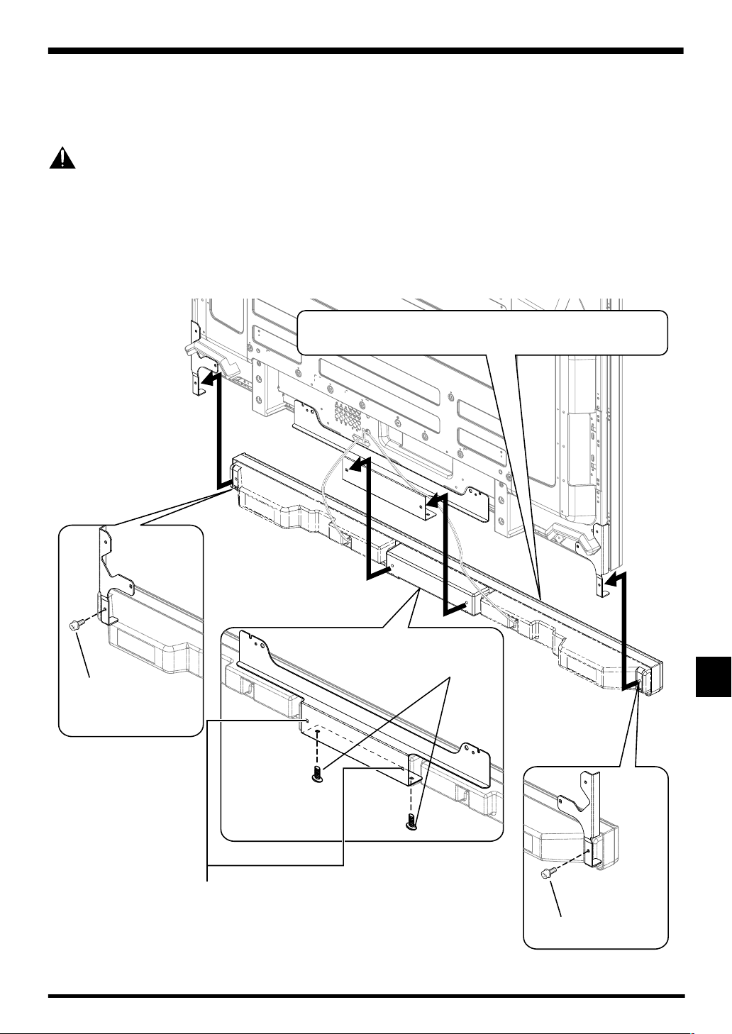
Español
Cuando emplee la unidad para colgar o para la pared:
En primer lugar, instale la pantalla de plasma en la pared sólo con los accesorios de montaje del altavoz y el cable de altavoz
acoplados a la pantalla, y luego monte el altavoz. (Consulte la página 34)
Para facilitar las conexiones de los cables, le recomendamos completar las conexiones de cables de los lados de la pantalla de
plasma antes de montar el altavoz en la pantalla de plasma.
Precaución
Tenga cuidado con los accesorios de montaje del altavoz cuando efectúe la instalación o la conexión. Esta situación le haría
correr el peligro de heridas.
3. Conecte los cables de altavoz suministrados a la parte posterior de la pantalla de plasma.
4. Coloque la pantalla de plasma en los accesorios de montaje de la unidad para
colgar o para la pared.
• Para los detalles, consulte el manual de instrucciones suministrado con la unidad para colgar o para la pared.
5. Conecte el otro extremo de los cables de altavoz al altavoz.
6. Ponga el altavoz en los accesorios de
montaje de altavoz en la dirección correcta.
4
Tornillo de montaje del
altavoz (M5 x 10 mm)
Tornillo de montaje del
altavoz (M5 x 10 mm)
2
1
Cuando emplee la unidad
para colgar o para la pared,
no emplee estos orificios.
3
Tornillo de montaje del
altavoz (M5 x 10 mm)
7. Fíjelos empleando los tornillos suministrados (4 lugares).
• Apriete los cuatro tornillos siguiendo el orden de 1, 2, 3 y luego 4 como se indica en la ilustración.
Español
37
Page 38
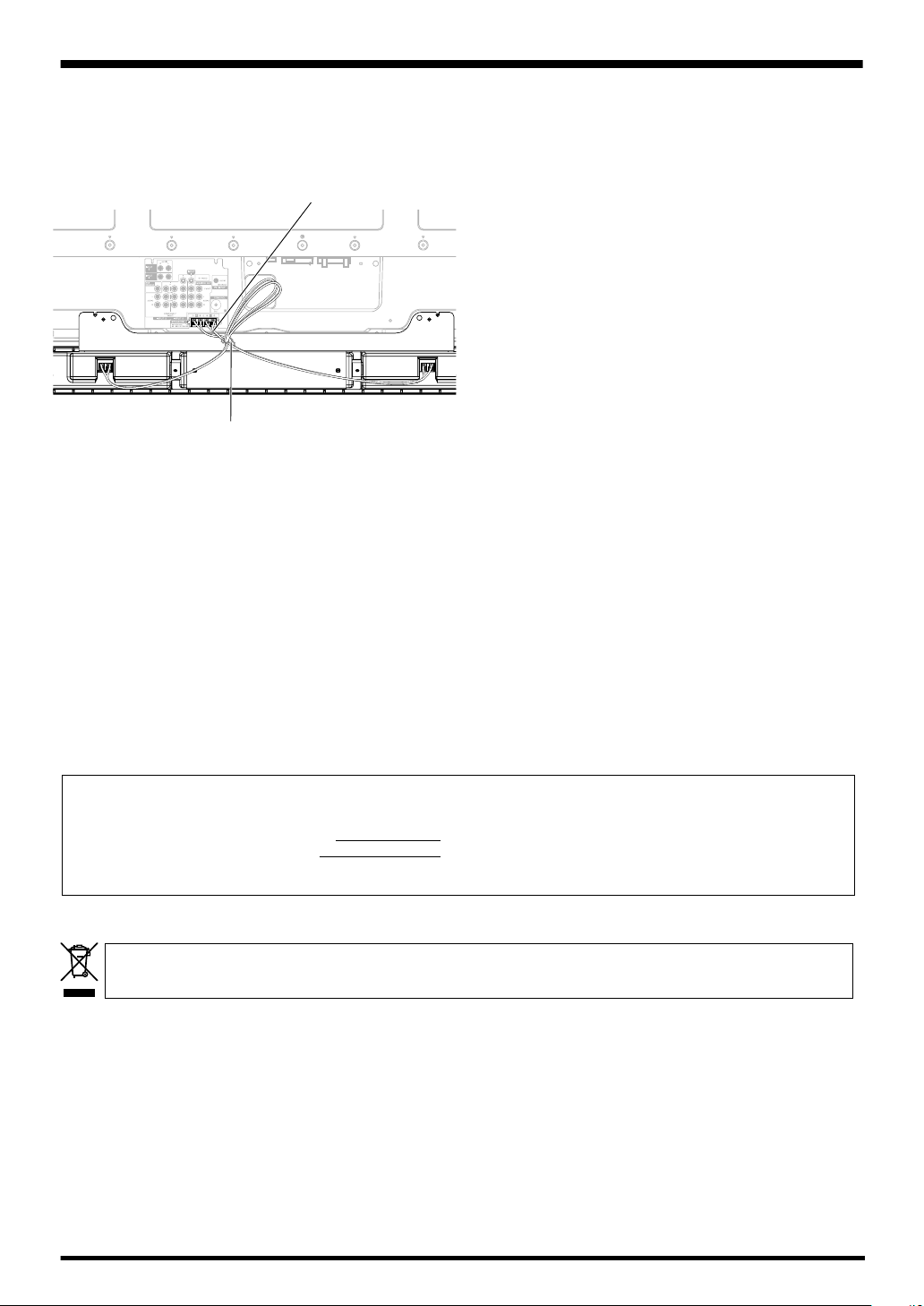
Español
CÓMO ENCAMINAR LOS CABLES
Se incluyen bandas de cuentas con la pantalla de plasma.
Para arreglar los cables de altavoz, utilice las bandas de
cuentas cuando sea necesario.
Cable de altavoz
Parte posterior
de la pantalla
Banda de la base
MANTENIMIENTO DEL GABINETE
• Para quitar la suciedad y el polro utilice un paño de limpieza
o paño seco.
• Cuando la superficie está muy sucia, limpie con un paño
embebido en algún agente limpiador neutro diluido cinco
o seis veces en agua, exprima bien, y luego vuelva a
limpiar con un paño seco. No utilice ceras o agentes
limpiadores para muebles.
• No utilice diluyentes, bencinas, rociadores de insecticidas
ni otros agentes químicos sobre o cerca de esta unidad,
ya que puede corroer las superficies.
• Cuando se usa un paño químico, lea las instrucciones para
el cuidado del paño químico.
ESPECIFICACIONES
Caja acústica: Tipo reflejo de bajos
Altavoces usados (sistema de dos vías):
Altavoz de graves (para los sonidos graves)
............................................. Tipo cónico 4,8 cm × 13 cm
Altavoz de agudos (para los sonidos agudos)
...............................................Tipo semicúpula de 2,5 cm
Impedancia nominal ...................................................... 8 Ω
Gama de frecuencias............................. 66 Hz a 30 000 Hz
Sensibilidad (1 m, 1 W) ............................................. 80 dB
Entrada permisible:
Entrada máxima ....................................................... 13 W
Entrada nominal ........................................................ 4 W
Frecuencia de cruce .................................................. 3 kHz
Dimensiones exteriores
.................... 1 470 mm (An) × 87 mm (Al) × 115 mm (Pr)
Peso .......................................................................... 3,8 kg
Partes accesorias
.......................................................... Cable de altavoz × 2
............................................................................ Ménsula
Derecho × 1
Izquierdo × 1
Central × 1
.............................................. Tornillo (M5 × 10 mm) × 12
................................................................... Llave Allen x 1
.............................................Manual de instrucciones × 1
NOTA:
Las especificaciones y diseño están sujetos a posibles
cambios sin previo aviso, con el objeto de mejoras en el
producto.
AVISO IMPORTANTE
– ANOTE MÁS ABAJO EL NÚMERO DE MODELO Y EL NÚMERO DE SERIE DE ESTE EQUIPO.
LOS ENCONTRARÁ DETALLADOS EN LA PARTE POSTERIOR DEL MISMO.
N.º DE MODELO
N.º DE SERIE
GUARDE ESTOS NÚMEROS PARA FUTURAS REFERENCIAS.
Si desea deshacerse de este producto, no lo mezcle con los residuos generales de su hogar. De conformidad con la legislación
vigente, existe un sistema de recogida distinto para los productos electrónicos que requieren un procedimiento adecuado de
tratamiento, recuperación y reciclado.
Las viviendas privadas en los 25 estados miembros de la UE, en Suiza y Noruega pueden devolver gratuitamente sus productos electrónicos
usados en las instalaciones de recolección previstas o bien en las instalaciones de minoristas (si adquieren un producto similar nuevo).
En el caso de los países que no se han mencionado en el párrafo anterior, póngase en contacto con sus autoridades locales a fin de conocer el
método de eliminación correcto.
Al actuar siguiendo estas instrucciones, se asegurará de que el producto de desecho se somete a los procesos de tratamiento, recuperación y
reciclaje necesarios, con lo que se previenen los efectos negativos potenciales para el entorno y la salud humana.
Publicado por Pioneer Corporation.
Copyright © 2006 Pioneer Corporation.
Todos los derechos reservados.
K058_Sp
38
Page 39

AFTER-SALES SERVICE FOR PIONEER PRODUCTS
Please contact the dealer or distributor from where you purchased the
product for its after-sales service (including warranty conditions) or any
other information. In case the necessary information is not available,
please contact the Pioneer's subsidiaries (regional service headquarters)
listed below:
PLEASE DO NOT SHIP YOUR PRODUCT TO THE COMPANIES at the
addresses listed below for repair without advance contact, for these
companies are not repair locations.
AMERICA
PIONEER ELECTRONICS (USA) INC.
CUSTOMER SUPPORT DIVISION
P.O. BOX 1760, LONG BEACH, CA 90801-1760, U.S.A.
CUSTOMER SERVICE HOTLINE : (800) 421-1625
EUROPE
PIONEER EUROPE NV
EUROPEAN SERVICE DIVISION
HAVEN 1087, KEETBERGLAAN 1, B-9120 MELSELE, BELGIUM
ASEAN
PIONEER ELECTRONICS ASIACENTRE PTE. LTD.
SERVICE DEPARTMENT
253, ALEXANDRA ROAD #04-01 SINGAPORE 159936
JAPAN AND OTHERS
PIONEER CORPORATION (HEAD OFFICE)
CUSTOMER SUPPORT CENTER
4-1, MEGURO 1-CHOME, MEGURO-KU, TOKYO 153-8654 JAPAN
Published by Pioneer Corporation
Copyright © 2006 Pioneer Corporation
All rights reserved
Printed in China / Imprimé en Chine <SRD1332-A>
 Loading...