

Page 1

PLASMA DISPLAY SYSTEM
SYSTEME D’ÉCRAN PLASMA
PLASMA DISPLAY-SYSTEM
PDP-506XDE
PDP-436XDE
Discover the benefits of registering your product online at
www.pioneer.co.uk (or www.pioneer-eur.com).
Découvrez les nombreux avantages offerts en enregistrant votre produit
en ligne maintenant sur www.pioneer.fr (ou www.pioneer-eur.com).
Bitte nutzen Sie die Möglichkeit zur Registrierung Ihres Produktes unter
www.pioneer.de (oder www.pioneer-eur.com)
Operating Instructions
Mode d’emploi
Bedienungsanleitung
Page 2

Page 3
English
WARNING
This equipment is not waterproof. To prevent a fire or shock
hazard, do not place any container filed with liquid near
this equipment (such as a vase or flower pot) or expose it to
dripping, splashing, rain or moisture.
This product complies with the Low Voltage Directive (73/23/EEC,
amended by 93/68/EEC), EMC Directives (89/336/EEC, amended by
92/31/EEC and 93/68/EEC).
D3-4-2-1-3_A_En
WARNING
Before plugging in for the first time, read the following
section carefully.
The voltage of the available power supply differs according
to country or region. Be sure that the power supply voltage
of the area where this unit will be used meets the required
voltage (e.g., 230V or 120V) written on the rear panel.
D3-4-2-1-4_A_En
WARNING
This apparatus must be earthed.
WARNING
This product equipped with a three-wire grounding
(earthed) plug - a plug that has a third (grounding) pin. This
plug only fits a grounding-type power outlet. If you are
unable to insert the plug into an outlet, contact a licensed
electrician to replace the outlet with a properly grounded
one. Do not defeat the safety purpose of the grounding
plug.
D3-4-2-1-6_A_En
The following symbols are found on
labels attached to the product. They alert
the operators and service personnel of
this equipment to any potentially
dangerous conditions.
WARNING
This symbol refers to a hazard or unsafe
practice which can result in personal
injury or property damage.
CAUTION
This symbol refers to a hazard or unsafe
practice which can result in severe
personal injury or death.
WARNING
To prevent a fire hazard, do not place any naked flame
sources (such as a lighted candle) on the equipment.
VENTILATION CAUTION
When installing this unit, make sure to leave space around
the unit for ventilation to improve heat radiation. For the
minimum space required, see page 16.
WARNING
Slots and openings in the cabinet are provided for
ventilation to ensure reliable operation of the product, and
to protect it from overheating. To prevent fire hazard, the
openings should never be blocked or covered with items
(such as newspapers, table-cloths, curtains) or by operating
the equipment on thick carpet or a bed.
D3-4-2-1-7a_A_En
CAUTION
The power switch does not completely separate the unit
from the mains in off position. Therefore install the unit
suitable places easy to disconnect the mains plug in case of
the accident. The mains plug of unit should be unplugged
from the wall socket when left unused for a long period of
time.
STANDBY/ON Button
STANDBY:
When placed into the standby mode, the main
power flow is cut and the unit is no longer fully
operational.
STANDBY/ON Indicator
The indicator is lit red when the unit is in the standby mode
and is lit blue when it is in the power-on mode.
Page 4

Contents
Contents
Thank you for buying this Pioneer product.
Please read through these operating instructions so you will know how to operate your model properly. After you have finished
reading the instructions, put them away in a safe place for future reference.
In some countries or regions, the shape of the power plug and power outlet may sometimes differ from that shown in the
explanatory drawings. However the method of connecting and operating the unit is the same.
01 Important User Guidance Information
02 Safety Precautions
03 Supplied Accessories
Identifying the main units ........................12
Plasma Display ..........................................12
Media Receiver ..........................................12
04 Part Names
Plasma Display ..........................................13
Media Receiver ..........................................14
Remote control unit ..................................15
05 Preparation
Installing the Plasma Display ..................16
Installing the Media Receiver ..................16
Preventing the Plasma Display from
Falling Over ................................................17
Connecting the system cable ..................18
Connecting the power cord ......................19
Routing cables ..........................................20
Connecting to an antenna ........................21
Preparing the remote control unit ...........22
Inserting batteries ................................22
Cautions regarding batteries ...............22
Allowed operation range of the
remote control unit ...............................22
Cautions regarding the remote
control unit ............................................22
06 Watching TV
Turning on/off the power ..........................23
Changing channels ...................................24
Tuning to your favourite (analogue)
channels ....................................................25
Changing the volume and sound ............25
Use the multiscreen functions ................27
Splitting the screen ..............................27
Freezing images ...................................28
07 Menu Setup
Using the menu .........................................29
AV mode menus ...................................29
PC mode menus ...................................29
4
En
Menu operations .................................. 29
08 Basic Adjustment Settings
Setting up TV channels automatically .... 30
Using Auto Installation ....................... 30
Setting up analogue TV channels
manually ................................................... 30
Using Manual Adjust .......................... 30
Reducing video noise .......................... 31
Setting Child Lock ............................... 31
Selecting a decoder input terminal ... 31
Labelling TV channels ......................... 32
Sorting preset TV channels ................. 32
Clock setting ........................................ 32
Language setting ...................................... 32
AV Selection ............................................. 33
Basic picture adjustments ...................... 33
Advanced picture adjustments ............... 34
Using PureCinema .............................. 34
Using Colour Temp .............................. 34
Using CTI .............................................. 34
Using Colour Management ................ 35
Eliminating noise from images .......... 35
Using the Dynamic Range Expander
(DRE) functions ................................... 35
Using the 3DYC and I-P Mode ............ 36
Sound adjustments .................................. 36
FOCUS .................................................. 36
Front Surround .................................... 37
Listening to audio from the sub
screen using headphones ....................... 37
Power Control ........................................... 38
09 Enjoying DTV broadcasts
Watching DTV programmes .................... 39
Changing channels ............................. 39
Viewing a channel banner .................. 39
Viewing subtitles .................................. 39
Reconfiguring the DTV channel
settings ...................................................... 40
Reselecting a country ......................... 40
Replacing the existing channels ........ 40
Adding new channels ......................... 40
Checking signal strength .................... 41
Page 5

Contents
Switching on/off the power to the
antenna ................................................ 41
Restoring the system defaults ............ 41
Customizing channel related settings .... 42
Setting Channel Options ..................... 42
Activating the Favourites function ..... 42
Activating the Auto Skip ..................... 42
Setting the Child Lock ......................... 43
Sorting preset DTV channels .............. 43
Selecting a digital audio format .............. 43
Selecting languages for audio, subtitles,
and teletext ............................................... 44
Using Software Update ............................ 44
Using Auto Update .............................. 44
Setting Update Time ............................ 44
Starting Manual Update ...................... 44
Displaying technical information ....... 45
Using MHEG application (UK only) .... 45
Screen Saver ............................................. 45
Common Interface ................................... 45
Inserting a CA Card ............................. 45
10 Using the Electronic Programme Guide
(EPG)(for Analogue TV only)
Setting up for using the EPG ................... 46
Updating EPG information
automatically ........................................ 46
Specifying an EPG information
provider ................................................. 46
Restricting the display of EPG
information ........................................... 46
Searching programmes ........................... 46
Viewing programme information ............ 47
Recording a programme using a
recording equipment ............................... 47
Selecting a programme for immediate
watching ................................................... 47
11 Using the Electronic Programme Guide
(EPG)(for DTV only)
EPG display format ................................... 48
Using the EPG .......................................... 49
Presetting TV programmes using the
EPG ............................................................ 50
Using auto channel select and standby
recording .............................................. 50
Setting the timer manually ................. 51
Priority rules for overlapped
presettings ........................................... 51
Changing/cancelling TV programme
presettings ............................................ 52
Changing priorities for overlapped
presettings ............................................ 52
Using other useful EPG functions .......... 53
EPG Jump ............................................. 53
EPG Search ..........................................53
12 Useful Adjustment Settings
Switching the vertical drive frequency
(AV mode only) ......................................... 54
Adjusting image positions
(AV mode only) ......................................... 54
Adjusting image positions and clock
automatically (PC mode only) ................. 54
Adjusting image positions and clock
manually (PC mode only) ......................... 54
Selecting an input signal type ................. 55
Colour system setting (AV mode only) ... 55
Selecting a screen size manually ............ 56
Selecting a screen size automatically .... 57
Selecting a screen size for received
4:3 aspect ratio signals ....................... 57
Changing the brightness at both sides
of the screen (Side Mask) ........................ 57
Sleep Timer ............................................... 58
Using a password (AV mode only) .......... 58
Entering a password ............................ 58
Changing the password ...................... 58
Resetting the password function ....... 59
Disabling the password function ....... 59
13 Enjoying through External Equipment
Watching a decoder image ..................... 60
Connecting a decoder ......................... 60
Displaying a decoder image ............... 60
Watching a VCR image ............................ 60
Connecting a VCR ................................ 60
Displaying a VCR image ...................... 60
Using HDMI Input .................................... 61
Connecting HDMI equipment ............ 61
Using i/o Link.A ........................................ 62
Watching a DVD image ........................... 63
Connecting a DVD player .................... 63
Displaying a DVD image ..................... 63
Using the SCART output function ........... 63
Switching the SCART output .............. 64
Enjoying a game console or watching
camcorder images ...................................64
English
5
En
Page 6

Contents
Connecting a game console or
camcorder .............................................64
Displaying an image from the game
console or camcorder ..........................64
Watching an image from a personal
computer ...................................................65
Connecting a personal computer .......65
Displaying an image from a personal
computer ...............................................65
Computer compatibility chart .............65
Enjoying through audio equipment in
connection .................................................65
Connecting audio equipment ..............65
Connecting control cords .........................66
About SR+ ............................................66
Enjoying through memory cards
(Home Gallery function) ...........................66
Readable memory cards ......................66
Readable data files ...............................66
Inserting a memory card .....................67
Removing a memory card ...................67
Starting the initial Home Gallery
screen ....................................................67
Selecting a folder .................................67
Starting a thumbnail screen ................68
Starting a standard single-image
screen ....................................................68
Starting the Slide Show Setup
screen ....................................................69
Starting the Slide Show screen ...........69
Adjusting the picture quality ...............69
Controlling other equipment using the
supplied remote control unit ....................69
Manufacture codes ..............................70
STB (set - top box) control buttons .....71
DVD/DVR control buttons ....................72
VCR control buttons .............................73
15 Appendix
Troubleshooting ....................................... 76
Connecting pin assignments for
SCART ....................................................... 77
Specifications ........................................... 78
14 Using the Teletext Functions
What is Teletext? .......................................74
Operating the Teletext basics ..................74
Turning on and off Teletext ..................74
Selecting and operating Teletext
pages .....................................................74
Displaying subpages ................................75
Displaying TOP Over View ...................75
Displaying subtitle pages ....................75
6
En
Page 7

Important User Guidance Information
Important User Guidance Information
01
In order to obtain maximum enjoyment from this Pioneer
PureVision PDP-506XDE/PDP-436XDE Plasma Display
System, please first read this information carefully.
With the Pioneer PureVision PDP-506XDE/PDP-436XDE, you
can be assured of a high quality Plasma Display System with
long-life and high reliability. To achieve images of exceptional
quality, this Pioneer Plasma Display System incorporates
state-of-the-art design and construction, as well as very precise
and highly advanced technology.
The Pioneer PureVision PDP-506XDE/PDP-436XDE
incorporates the latest in colour filter technology
Colour Filter. This improves the colour/picture reproduction of
these models as compared to previous models. It also
eliminates the need for a physical glass panel to be placed in
front of the plasma panel, which furthers Pioneer’s continued
goal of reducing environmental waste in consumer
electronics, now during the manufacturing process and in the
future during the recycling process.
Over the course of its lifetime, the luminosity of the Pioneer
PDP-506XDE/PDP-436XDE Plasma Display System will
diminish very slowly, such as with all phosphor-based screens
(for example, a traditional tube-type television). To enjoy
beautiful and bright images on your Pioneer Plasma Display
System for a long time, please carefully read and follow the
usage guidances below:
—
Direct
Usage guidelines
All phosphor-based screens (including conventional tube-type
televisions) can be affected by displaying static images for a
prolonged period. Plasma Display System’s are no exception to
this rule. After-image and permanent effects on the screen can
be avoided by taking some basic precautions. By following the
recommendations listed below, you can ensure longer and
satisfactory results from your plasma:
• Whenever possible, avoid frequently displaying the same
image or virtually still moving pictures (e.g. closed-captioned
images or video game images which have static portions).
• Do not display Teletext for a prolonged period of time.
• Avoid viewing the On Screen Display for extended periods,
from a decoder, DVD player, VCR and all other components.
• Do not leave the same picture freeze-framed or paused
continuously over a long period of time, when using the still
picture mode from a TV, VCR, DVD player or any other
component.
• Images which have both very bright areas and very dark
areas side by side should not be displayed for a prolonged
period of time.
• When playing a game, the “GAME” mode setting within “AV
Selection” is strongly recommended. However, please limit
its use to less than 2 hours at a time.
• After playing a game, or displaying a PC image or any still
image, it is best to view a normal moving picture in the
“WIDE” or “FULL” screen setting for more than 3 times the
length of the previous still moving image.
• After using the Plasma Display System, always switch the
display to “STANDBY” mode.
This product should be installed by using only parts and
accessories designed by PIONEER. Use of accessories other
than the PIONEER stand or installation bracket may result in
instability, and could cause injury. For custom installation,
please consult the dealer where the unit was purchased. To
ensure correct installation, experienced and qualified experts
must install the unit. PIONEER will not be held responsible for
accident or damage caused by the use of parts and
accessories manufactured by other companies.
To avoid malfunction and overheating, make sure that the
vents on the main unit are not blocked when installing to
ensure proper heat emission:
• Distance the unit slightly from other equipment, walls, etc.
For the minimum space required around the unit, see page
16.
• Do not fit the unit inside narrow spaces where ventilation is
poor.
• Do not cover with a cloth, etc.
• Clean the vents on the sides and rear of the unit to remove
dust build-up, by using a vacuum cleaner set to its lowest
suction setting.
• Do not place the product on a carpet or blanket.
• Do not leave the product tilted over except the case of vertical
installation of the Media Receiver.
• Do not reverse the product.
Using the unit without proper ventilation may cause the
internal temperature to rise, and could result in possible
malfunction. When the surrounding or internal temperature
exceeds a certain degree, the display will automatically power
off in order to cool the internal electronics and prevent
hazardous occurrences.
Any malfunction may occur due to: an inappropriate
installation site, improper assembly, installation, mounting, or
operation of this product, modifications made to the product.
However, PIONEER cannot be held responsible for such
accidents or malfunction.
NOTE
The following are typical effects and characteristics of a
phosphor-based matrix display and as such, are not covered by
the manufacturer’s limited warranties:
• Permanent residual images upon the phosphors of the
panel.
• The existence of a minute number of inactive light cells.
• Panel generated sounds, examples: Fan motor noise, and
electrical circuit humming / glass panel buzzing
English
Installation guidelines
The Pioneer PureVision PDP-506XDE/PDP-436XDE Plasma
Display System incorporates a very thin design. To ensure
safety, please take the proper measures to mount or install the
Plasma Display, in order to prevent the unit from tipping over
in the event of vibration or accidental movement.
7
En
Page 8

01
Important User Guidance Information
CAUTION
PIONEER bears no responsibility for any damage arising from
incorrect use of the product by you or other people,
malfunctions when in use, other product related problems,
and use of the product except in cases where the company
must be liable.
Plasma Display protection function
When still images (such as photos and computer images) stay
on the screen for an extended period of time, the screen will be
slightly dimmed. This is because the protection function of the
Plasma Display automatically adjusts the brightness to protect
the screen when detecting still images; so this does not
designate malfunction. The screen is dimmed when a still
image is detected for about three minutes.
Information of pixel defect
Plasma screens display information using pixels. Pioneer
plasma display panels contain a very large number of pixels.
(Depending on the panel size; over 2.3 million cells in case of a
43 inch display, over 2.9 million pixels in case of a 50 inch
display, over 3.1 million cells in case of a 61 inch display). All
Pioneer display panels are manufactured using a very high
level of ultra-precision technology and undergo individual
quality control.
In rare cases, some pixels can be permanently switched off, or
on, resulting in either a black or coloured pixel permanently
fixed on the screen.
This effect is common to all plasma displays because it is a
consequence of the technology.
If the defective pixels are visible at a normal viewing distance
of between 2.5 and 3.5 meters whilst viewing a normal
broadcast (i.e. not a test card, still image or single colour
display) please contact the supplying dealer.
If, however, they can only be seen close up or during single
colour displays then this is considered normal for this
technology.
Infrared rays
The Plasma Display releases infrared rays because of its
characteristics. Depending on how the Plasma Display is in
use, the remote controls of nearby equipment may be
adversely affected or wireless headphones using infrared rays
are interfered by noise. If this is the case, place that equipment
at a location where its remote control sensor is not affected.
Radio interference
While this product meets the required specifications, it emits a
small amount of noise. If you place such equipment as an AM
radio, personal computer, and VCR close to this product, that
equipment may be interfered. If this happens, place that
equipment far enough from this product.
Plasma Display driving sound
The screen of the Plasma Display is composed of extremely
fine pixels and these pixels emit light according to received
video signals. This principle may make you hear buzz sound or
electrical circuit hamming from the Plasma Display.
Also note that the rotation speed of the cooling fan motor
increases when the ambient temperature of the Media
Receiver becomes high. You may hear the sound of the fan
motor at that time.
Do not attach such items as labels and tape to the
product.
• This may result in the discolouration or scratch of the
cabinet.
When not using the product for a long period of
time
• If you do not use the product for a long period of time, the
functions of the product may be adversely affected. Switch
on and run the product occasionally.
Condensation
• Condensation may take place on the surface or inside of the
product when the product is rapidly moved from a cold place
to a warm place or just after a heater is switched on in winter
morning, for example. When condensation takes place, do
not switch on the product and wait until condensation
disappears. Using the product with condensation may result
in malfunction.
Cleaning the surface of the screen and the glossy
surface of the front cabinet
• When cleaning the surface of the screen or the glossy
surface of the front cabinet, gently wipe it with a dry soft
cloth; the supplied cleaning cloth or other similar cloths
(e.g., cotton and flannel). If you use a dusty or hard cloth or
if you rub the screen hard, the surface of the product will be
scratched.
• If you clean the surface of the screen with a wet cloth, water
droplets on the surface may enter into the product, resulting
in malfunction.
Cleaning the cabinet
• When cleaning the cabinet of this product, gently wipe it
with a clean soft cloth (e.g., cotton and flannel). If you use a
dusty or hard cloth or if you rub the cabinet hard, the surface
of the cabinet will be scratched.
• The cabinet of this product is mostly composed of plastic. Do
not use chemicals such as benzene or thinner to clean the
cabinet. Using these chemicals may result in quality
deterioration or coating removal.
• Do not expose the product to volatile gas or fluid such as
pesticide. Do not make the product contact with rubber or
vinyl products for a long period of time. The effect of
plasticizer in the plastic may result in quality deterioration or
coating removal.
• If you clean the surface of the cabinet with a wet cloth, water
droplets on the surface may enter into the product, resulting
in malfunction.
Handles at the rear of the Plasma Display
• Do not remove the handles from the rear of the Plasma
Display.
• When moving the Plasma Display, ask another person for
help and use the handles attached to the rear of the Plasma
Display. Do not move the Plasma Display by holding only a
single handle. Use the handles as shown.
• Do not use the handles to hang the product when installing
or carrying the product, for example. Do not use the handles
for the purpose of preventing the product from tilting over.
8
En
Page 9

Important User Guidance Information
CAUTION
Panel sticking and after-image lag
• Displaying the same images such as still images for a long
time may cause after-image lagging. This may occur in the
following two cases.
1 After-image lagging due to remaining electrical load
When image patterns with very high peak luminance are
displayed for more than 1 minute, after-image lagging may
occur due to the remaining electric load. The after-images
remaining on the screen will disappear when moving images
are displayed. The time for the after-images to disappear
depends on the luminance of the still images and the time they
had been displayed.
2 After-image (lag image) due to burning
Avoid displaying the same image on the Plasma Display
continuously over a long period of time. If the same image is
displayed continuously for several hours, or for shorter periods
of time over several days, a permanent after-image may remain
on the screen due to burning of the fluorescent materials.
Such images may become less noticeable if moving images
are later displayed, but they will not disappear completely.
• The energy save function can be set to help prevent damage
from screen burning (see page 38).
01
English
CAUTION
• The compatibility of this product with digital terrestrial
services has been fixed - details described in the product
specifications - at the time of its introduction.
If you want to dispose this product, do not mix it with general household waste. There is a separate collection system for used electronic products in
accordance with legislation that requires proper treatment, recovery and recycling.
Private households in the 25 member states of the EU, in Switzerland and Norway may return their used electronic products free of charge to designated collection
facilities or to a retailer (if you purchase a similar new one).
For countries not mentioned above, please contact your local authorities for the correct method of disposal.
By doing so you will ensure that your disposed product undergoes the necessary treatment, recovery and recycling and thus prevent potential negative effects on the
environment and human health.
9
En
Page 10

02
Safety Precautions
Safety Precautions
Electricity is used to perform many useful functions, but it can
also cause personal injuries and property damage if improperly
handled. This product has been engineered and manufactured
with the highest priority on safety. However, improper use can
result in electric shock and/or fire. In order to prevent potential
danger, please observe the following instructions when
installing, operating and cleaning the product. To ensure your
safety and prolong the service life of your product, please read
the following precautions carefully before using the product.
1. Read instructions — All operating instructions must be
read and understood before the product is operated.
2. Keep this manual in a safe place — These safety and
operating instructions must be kept in a safe place for
future reference.
3. Observe warnings — All warnings on the product and in
the instructions must be observed closely.
4. Follow instructions — All operating instructions must be
followed.
5. Cleaning — Unplug the power cord from the AC outlet
before cleaning the product. To clean the product, use the
supplied cleaning cloth or other soft clothes (e.g., cotton,
flannel). Do not use liquid cleaners or aerosol cleaners.
6. Attachments — Do not use attachments not
recommended by the manufacturer. Use of inadequate
attachments can result in accidents.
7. Water and moisture — Do not use the product near water,
such as bathtub, washbasin, kitchen sink and laundry tub,
swimming pool and in a wet basement.
8. Stand — Do not place the product on an unstable cart,
stand, tripod or table. Placing the product on an unstable
base can cause the product to fall, resulting in serious
personal injuries as well as damage to the product. Use
only a cart, stand, tripod, bracket or table recommended by
the manufacturer or sold with the product. When mounting
the product on a wall, be sure to follow the manufacturer’s
instructions. Use only the mounting hardware
recommended by the manufacturer.
9. When relocating the product placed on a cart, it must be
moved with utmost care. Sudden stops, excessive force
and uneven floor surface can cause the product to fall from
the cart.
10. Ventilation — The vents and other openings in the cabinet
are designed for ventilation. Do not cover or block these
vents and openings since insufficient ventilation can cause
overheating and/or shorten the life of the product. Do not
place the product on a bed, sofa, rug or other similar
surface, since they can block ventilation openings. This
product is not designed for built-in installation; do not
place the product in an enclosed place such as a bookcase
or rack, unless proper ventilation is provided or the
manufacturer’s instructions are followed.
11. Power source — This product must operate on a power
source specified on the specification label. If you are not
sure of the type of power supply used in your home, consult
your dealer or local power company.
12. Power cord protection — The power cords must be routed
properly to prevent people from stepping on them or
10
En
objects from resting on them. Check the cords at the plugs
and product.
13. The plasma Display used in this product is made of glass.
Therefore, it can break when the product is dropped or
applied with impact. Be careful not to be injured by broken
glass pieces in case the plasma Display breaks.
14. Overloading — Do not overload AC outlets or extension
cords. Overloading can cause fire or electric shock.
15. Entering of objects and liquids — Never insert an object
into the product through vents or openings. High voltage
flows in the product, and inserting an object can cause
electric shock and/or short internal parts. For the same
reason, do not spill water or liquid on the product.
16. Servicing — Do not attempt to service the product yourself.
Removing covers can expose you to high voltage and other
dangerous conditions. Request a qualified service person
to perform servicing.
17. Repair — If any of the following conditions occurs, unplug
the power cord from the AC outlet, and request a qualified
service person to perform repairs.
a. When the power cord or plug is damaged.
b. When a liquid was spilled on the product or when
objects have fallen into the product.
c. When the product has been exposed to rain or water.
d. When the product does not operate properly as
described in the operating instructions.
Do not touch the controls other than those described in
the operating instructions. Improper adjustment of
controls not described in the instructions can cause
damage, which often requires extensive adjustment
work by a qualified technician.
e. When the product has been dropped or damaged.
f. When the product displays an abnormal condition. Any
noticeable abnormality in the product indicates that the
product needs servicing.
18. Replacement parts — In case the product needs
replacement parts, make sure that the service person uses
replacement parts specified by the manufacturer, or those
with the same characteristics and performance as the
original parts. Use of unauthorized parts can result in fire,
electric shock and/or other danger.
19. Safety checks — Upon completion of service or repair work,
request the service technician to perform safety checks to
ensure that the product is in proper operating condition.
20. Wall or ceiling mounting — When mounting the product
on a wall or ceiling, be sure to install the product according
to the method recommended by the manufacturer.
21. Heat sources — Keep the product away from heat sources
such as radiators, heaters, stoves and other heatgenerating products (including amplifiers).
22. Unplug the power cord from the AC outlet before installing
the speakers.
23. Never expose the screen of the Plasma Display to a strong
impact, for example, by hitting it. The screen may be
broken, resulting in fire or personal injury.
24. Do not expose the Plasma Display to direct sunlight for a
long period of time. The optical characteristics of the front
protection panel changes, resulting in discolouration or
warp.
25. The Plasma Display weighs about 31.8 kg (70.1 lbs.) for the
PDP-506PE and about 25.8 kg (56.9 lbs.) for the PDP436PE. Because it has small depth and is unstable,
unpack, carry, and install the product with one more
person at least and use the handles.
Page 11
Safety Precautions
Installation Precautions
Observe the following precautions when installing with any items such as the optional stand.
When using the optional stand, brackets, or equivalent items
• Ask your dealer to perform the installation.
• Be sure to use the supplied bolts.
• For details, see the instruction manual that comes with the optional stand (or equivalent items).
When using other items
• Consult your dealer.
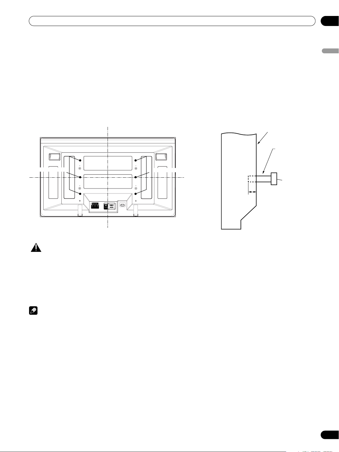
• The following six mounting holes can be used for the installation:
02
English
Rear view Side view
Mounting hole
Mounting hole
Plasma
Display
Mounting surface
Mounting
bracket (or
equivalent item)
Median line
M8 screw
12 to 18 mm
SYSTEM
CABLE
WHITE
BLACK
Median line
CAUTION
• Be sure to use four or more mounting holes symmetrical to the vertical and horizontal median lines.
• Use M8 screws, which go 12 to 18 mm in depth from the mounting surface of the Plasma Display. See the side view above.
• Be careful not to block the ventilation opening at the rear of the Plasma Display.
• Be sure to install the Plasma Display on a flat surface because it contains glass.
• The screw holes other than the above are to be used only for the specified products. Never use them for mounting non-specified
products.
• Do not mount or remove the Plasma Display to or from the stand, with speakers attached.
NOTE
• It is strongly recommended to use the optional PIONEER mounting products.
• PIONEER shall not be liable for any personal injury or product damage that results from the use of mounting items other than
the optional PIONEER products.
11
En
Page 12
03
Supplied Accessories
Supplied Accessories
Identifying the main units
Use the following table to check that you have received the correct Media Receiver and Plasma Display models.
Model Name of the Entire Plasma
Display System
PDP-506XDE
PDP-436XDE PDP-436PE
The speakers are available as options.
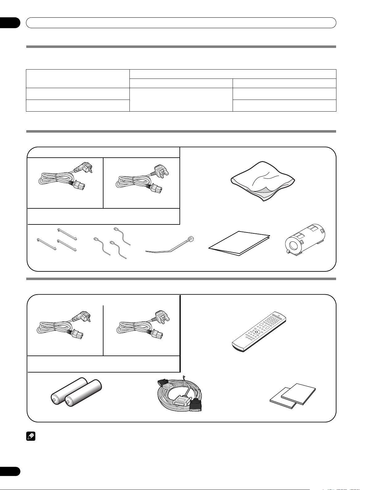
Media Receiver Plasma Display
Plasma Display
Power cord (2 m)
(For Europe, except UK
and Eire)
Only the power cord that is appropriate in your country or region
is supplied.
(For UK and Eire)
Model Name of the Main Unit
PDP-506PE
PDP-R06XE
Cleaning cloth
Speed clamp x 3 Bead band x 3 Warranty card
Cable tie
Media Receiver
Power cord (2 m)
(For Europe, except UK
and Eire)
Only the power cord that is appropriate in your country or region
is supplied.
AA size battery x 2
NOTE
• Always use the power cord supplied with the Plasma Display
and the one supplied with the Media Receiver for each
respective unit.
(For UK and Eire)
System cable (3 m)
Ferrite core
Remote control unit
Two operating instructions
12
En
Page 13
Part Names
Part Names
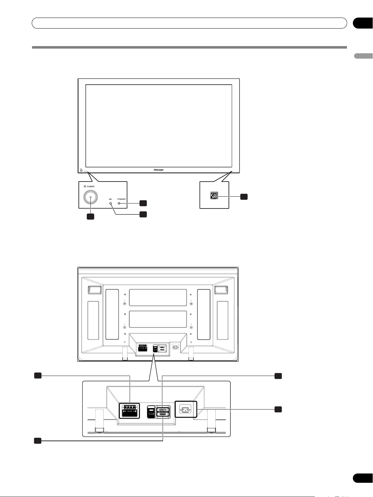
Plasma Display
Front view
04
English
4
2
1POWER
2
STANDBY indicator
button
Rear view
5
1
3
3
POWER ON indicator
4
Remote control sensor
SYSTEM
CABLE
WHITE
BLACK
7
6
5
SPEAKER (right/left) terminals
6
SYSTEM CABLE terminal (BLACK)
SYSTEM
CABLE
WHITE
BLACK
7
SYSTEM CABLE terminal (WHITE)
8
AC IN terminal
8
13
En
Page 14
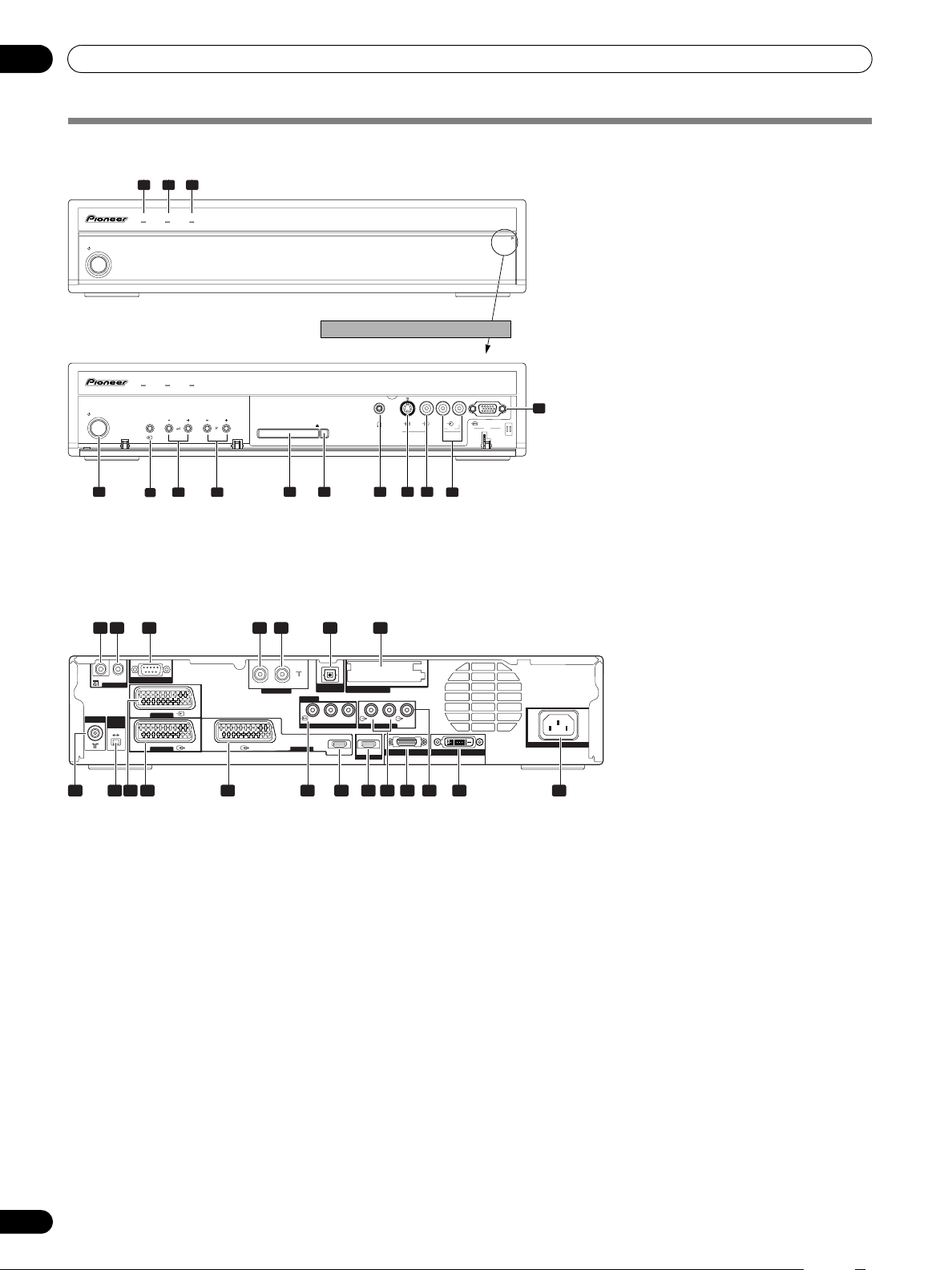
04
Part Names
Media Receiver
Front view
STANDBY/ON
STANDBY/ON
4
1 2 3
TIMERSTANDBYON
Pull this section to open the door.
TIMERSTANDBYON
INPUT VOLUME CHANNEL
6 7 13
5
PC CARD EJECT
8 9 10 11 12
S-VIDEOPHONES VIDEO AUDIOLR
INPUT 5
PC
ANALOG RGB
PC
1
POWER ON indicator
2
STANDBY indicator
3
TIMER indicator
PULL
OPEN
4 STANDBY/ON
5 INPUT
button
6VOLUME +/–
7 CHANNEL +/–
8
PC CARD slot
9 PC CARD EJECT
10
14
PHONES output terminal
11
INPUT 5 terminal (S-VIDEO)
12
INPUT 5 terminal (VIDEO)
13
INPUT 5/PC INPUT terminals
button
buttons
buttons
button
(AUDIO)
14
PC INPUT terminal (ANALOG RGB)
Rear view
182 3 4 5 6 7
IN OUT
SERVICE ONLY
CONTROL
ANT
1
CONTROL IN terminal
2
CONTROL OUT terminal
3
RS-232C terminal (used for factory setup)
4
ANT OUT terminal (Antenna through out)
5
ANT IN terminal (Antenna in for DTV)
INPUT 1
i /o link.A
SELECT
INPUT
2 3
INPUT 1
9 10 11 12 13 1614 15 17 18 19 20
ANT(DIGITAL)
INOUT
OPTICAL
DIGITAL OUT
COMMON INTERFACE
INPUT 2
Y
PB PR
R-AUDIO-L SUB
COMPONENT VIDEO
INPUT 3
HDMI HDMI
AUDIO OUTPUT
INPUT 4
WOOFER
BLACK
SYSTEM CABLE
WHITE
• Power can be supplied through this
terminal
6
DIGITAL OUT terminal (OPTICAL)
7
COMMON INTERFACE slot
• For a CA Module with a smart card
ANT (Antenna) input terminal
8
9
i/o link.A SELECT switch
AC IN
10
INPUT 1 terminal (SCART)
11
INPUT 2 terminal (SCART)
12
INPUT 3 terminal (SCART)
13
INPUT 2 terminal
(COMPONENT VIDEO: Y, P
14
INPUT 3 terminal (HDMI)
15
INPUT 4 terminal (HDMI)
16
AUDIO OUTPUT termimals
17
SYSTEM CABLE terminal (BLACK)
18
SUB WOOFER OUTPUT terminal
19
SYSTEM CABLE terminal (WHITE)
20
AC IN terminal
, PR)
B
14
En
Page 15
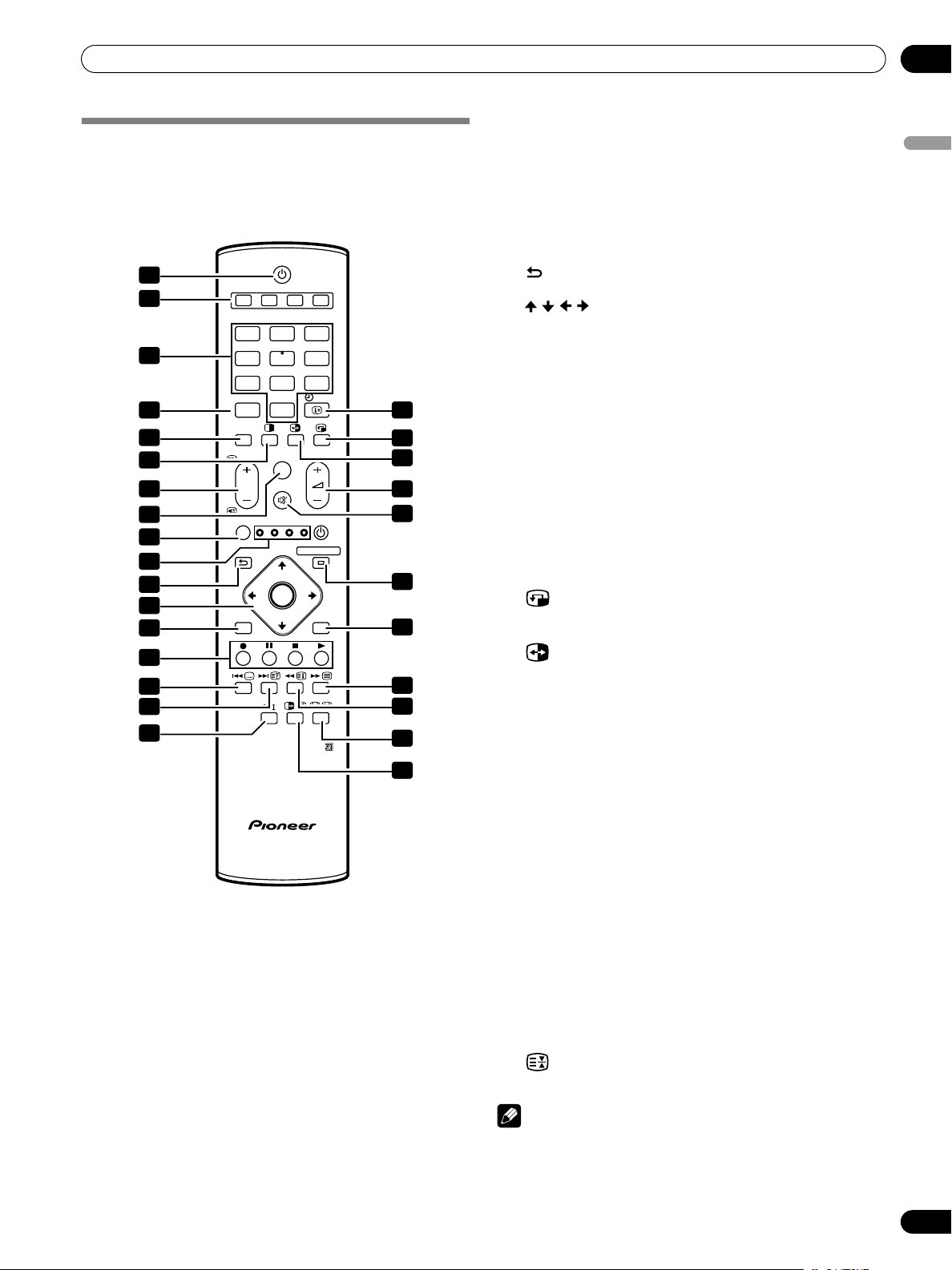
Part Names
Remote control unit
This section describes the functions of the buttons available
when the TV mode has been selected using the SELECT button.
For the buttons for controlling other equipment, see
“Controlling other equipment using the supplied remote
control unit” starting from page 69.
1
1
2
3
4 18
5
6
7
8
9
10
11
12
13
14
15
16
17
1 a
Turns on the power to the Plasma Display or places it into
the standby mode.
2 INPUT
Selects an input source of the Plasma Display. (INPUT 1,
INPUT 2, INPUT 3, INPUT 4)
3 0 – 9
TV/External input mode: Selects a channel.
TELETEXT mode: Selects a page.
4PC
Selects the PC terminal as an input source.
5 INPUT 5
Selects INPUT 5 as the input source of the Plasma Display.
6 c
Switches the screen mode among 2-screen, picture-inpicture, and single-screen.
7P +/P –
TV/External input mode: Selects a channel.
w/x
TELETEXT mode: Selects a page.
2 3 4
INPUT
1 2 3
4 5 6
7 8 9
PC
0
INPUT 5
TV/DTV
P
SELECT
RETURN
DVD/
TV
STB
VCR
DVR
HOME MENU
ENTER
EXIT EPG
DVD TOP MENU / GUIDE
DISC
DVD HDD
NAVI
INFO
SOURCE
MENU
19
20
21
22
23
24
25
26
27
28
8TV/DTV
Switches between the TV and DTV input modes.
9 SELECT
Switches the selection among TV, STB, DVD/DVR, and
VCR, so that you can control other equipment in
connection, using the supplied remote control unit.
10 TV, STB, DVD/DVR, VCR
These indicators show the current selection and status
when you control other equipment in connection using the
supplied remote control unit.
11 RETURN
Restores the previous menu screen.
12 /
/
Selects a desired item on the setting screen.
/
ENTER
Executes a command.
13 EXIT
Returns to the normal screen in one step.
14 Colour (RED/GREEN/YELLOW/BLUE)
TELETEXT mode: Selects a page.
15 [
TV/External input mode: Jumps to the Teletext subtitle page.
DTV input mode: Turns subtitle on and off.
16 k
TELETEXT mode: Displays hidden characters.
17 g
Sets the sound multiplex mode.
18 p y INFO
TV/External input mode: Displays the channel information.
DTV input mode: Displays the banner information.
19
Moves the location of the small screen when in the picturein-picture mode.
20
Switches between the two screens when in the 2-screen or
picture-in-picture mode.
21 i
+/
i
Sets the volume.
–
22 e
Mutes the sound.
23 HOME MENU
TV/External Input mode: Displays the Menu screen.
24 EPG
Display the Electronic Programme Guide.
25 m
Selects the TELETEXT mode.
(all TV image, all TEXT image, TV/TEXT image)
26 l
TELETEXT mode: Displays an Index page for the CEEFAX/FLOF
format. Displays a TOP Over View page for the TOP format.
27 f
TV/External input mode: Selects the screen size.
v
TELETEXT mode: Switches Teletext images. (full/upper
half/lower half)
28 d
TV/External input mode: Freezes a frame from a moving image.
Press again to cancel the function.
TELETEXT mode: Stops updating Teletext pages. Press
again to release the hold mode.
NOTE
• When using the remote control unit, point it at the Plasma Display.
04
English
15
En
Page 16
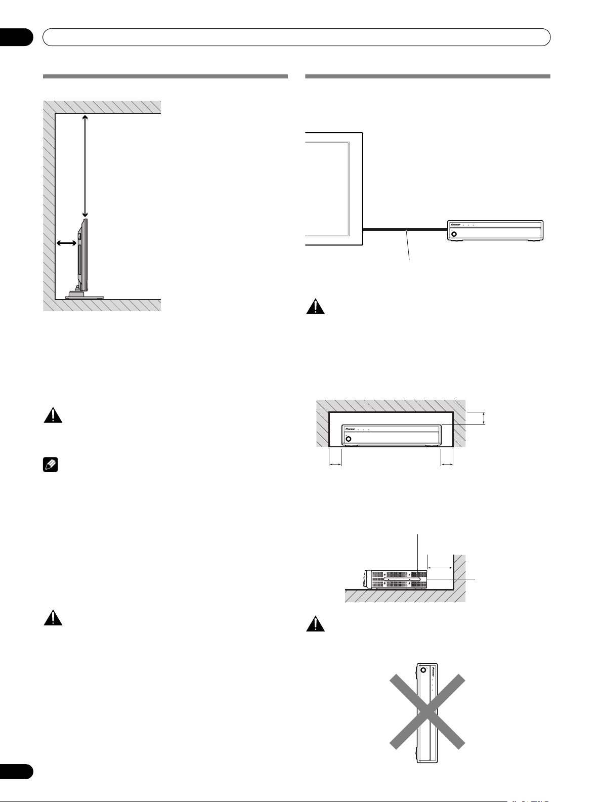
05
Preparation
Preparation
Installing the Plasma Display
Over 50 cm
Over
10 cm
Location
• Avoid direct sunlight. Maintain adequate ventilation.
• The length of the system cable used to connect the Plasma
Display and the Media Receiver is about 3 m.
• Because the Plasma Display is heavy, be sure to have
someone help you when moving it.
Installing the Media Receiver
Plasma Display
Media Receiver
TIMER
ON STANDBY
STANDBY/ON
System cable
(approx. 3 m)
CAUTION
• Do not place a VCR or any other device on the top
of the Media Receiver.
• When installing, allow enough space on the sides
and above the Media Receiver.
• Do not block the side ventilation opening or the
rear exhaust opening of the Media Receiver.
PULL
OPEN
CAUTION
• If you place anything on the top of the Media Receiver it will
not receive enough ventilation and will not operate properly.
NOTE
• Allow enough space around the upper and back parts when
installing to ensure adequate ventilation of the rear of the
unit.
Using the optional PIONEER stand
• For details on installation, refer to the instruction manual
supplied with the stand.
Using the optional PIONEER speakers
• For details on installation, refer to the instruction manual
supplied with the speaker.
CAUTION
Operating Environment
Operating environment temperature and humidity:
+0°C to +40°C; less than 85% RH (cooling vents not blocked)
Do not install this unit in a poorly ventilated area, or in
locations exposed to high humidity or direct sunlight (or strong
artificial light)
TIMER
ON STANDBY
STANDBY/ON
PULL
OPEN
Over 5 cm Over 5 cm
Ventilation
opening
Over 10 cm
Exhaust
opening
CAUTION
Placing the Media Receiver alone in the vertical position can
result in product damage and malfunction.
STANDBY/ON
ON STANDBY
TIMER
Over 5 cm
16
En
PULL
OPEN
Page 17
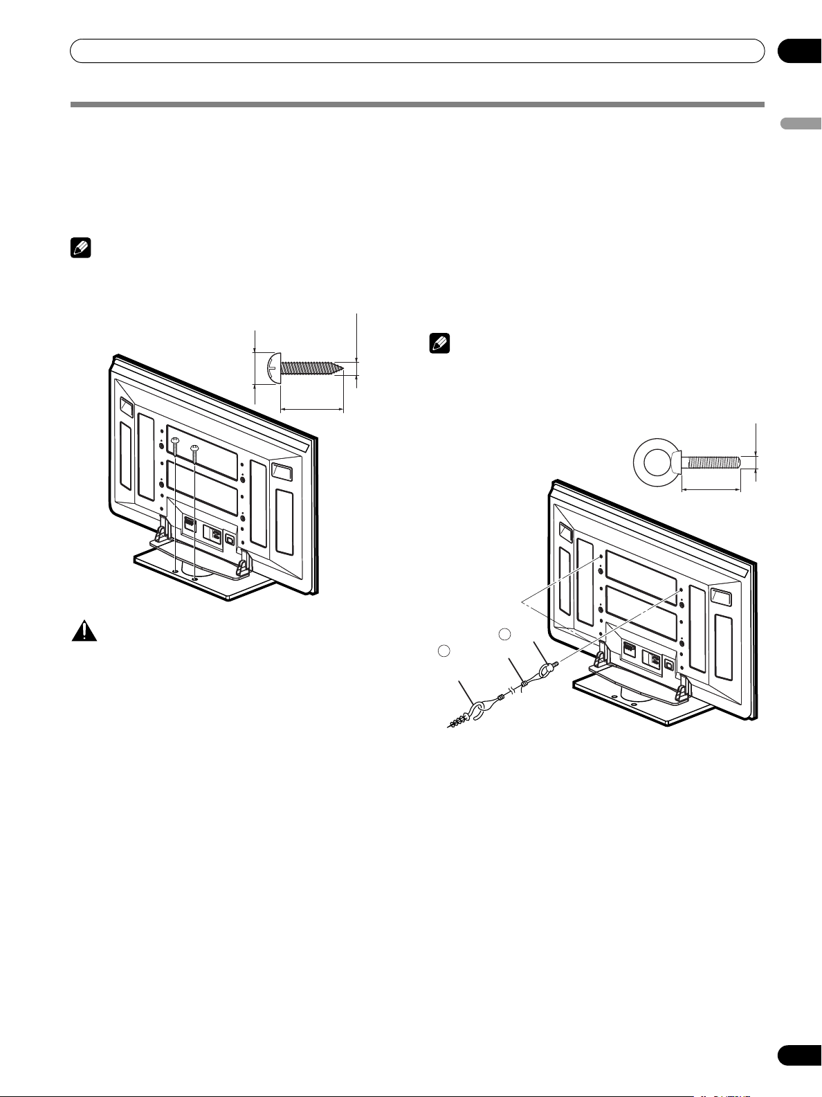
Preparation
Preventing the Plasma Display from Falling Over
After installing the stand, be sure to take special care to ensure that the Plasma Display will not fall over.
05
English
Stabilizing on a table or floor
Stabilize the Plasma Display as shown in the diagram using
screws that are available on the market.
NOTE
To stabilize the Plasma Display on a table or on the floor, use
screws that have a nominal diameter of 6 mm and that are at
least 20 mm long.
6 mm
9 to 15 mm
20 mm min.
Using a wall for stabilization
1. Attach falling prevention bolts (hooks) to
the Plasma Display.
2. Use strong cords or chains to stabilize it
appropriately and firmly to a wall, pillar, or
other sturdy element.
• Perform this work in the same way on the left and right sides.
NOTE
Use hooks, ropes, chains, and fittings that are available on the
market.
Recommended hook: Nominal diameter 8 mm Length 12 to 15
mm
8M
12 to 15 mm
CAUTION
A table or an area of the floor with adequate strength should
always be used to support the Plasma Display. Failure to do so
could result in personal injury and physical damage.
When installing the Plasma Display, please take the necessary
safety measures to prevent it from falling or overturning in case
of emergencies, such as earthquakes, or of accidents.
If you do not take these precautions, the Plasma Display could
fall down and cause injury.
The screws, hooks, chains and other fittings that you use to
secure the Plasma Display to prevent it from overturning will
vary according to the composition and thickness of the surface
to which it will be attached.
Select the appropriate screws, hooks, chains, and other fittings
after first inspecting the surface carefully to determine its
thickness and composition and after consulting a professional
installer if necessary.
2
Cord or chain
Fitting
Hook
1
17
En
Page 18
05
Preparation
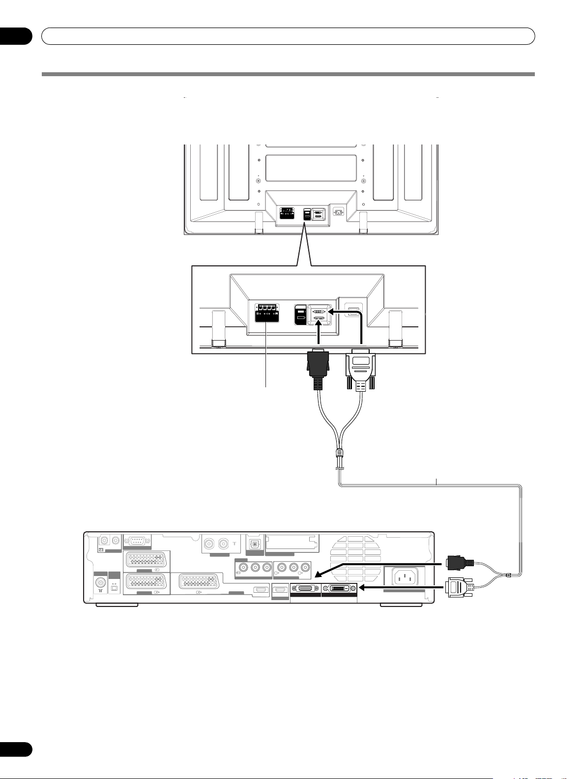
Connecting the system cable
Connecting the system cable to the Plasma Display
Plasma Display (rear view)
SYSTEM
CABLE
WHITE
BLACK
SYSTEM
CABLE
WHITE
BLACK
(BLACK)
For details on optional PIONEER speaker
installation, refer to the instruction manual that
came with the speaker.
Connecting the system cable to the Media Receiver
Media Receiver (rear view)
IN OUT
SERVICE ONLY
CONTROL
ANT
i /o link.A
SELECT
2 3
INPUT 1
INPUT
INPUT 1
ANT(DIGITAL)
INOUT
OPTICAL
DIGITAL OUT
Y
PB PR
COMPONENT VIDEO
HDMI HDMI
COMMON INTERFACE
R-AUDIO-L SUB
AUDIO OUTPUT
INPUT 4
INPUT 2
INPUT 3
WOOFER
BLACK
SYSTEM CABLE
WHITE
(WHITE)
System cable
(BLACK)
AC IN
(WHITE)
18
En
Page 19
Preparation
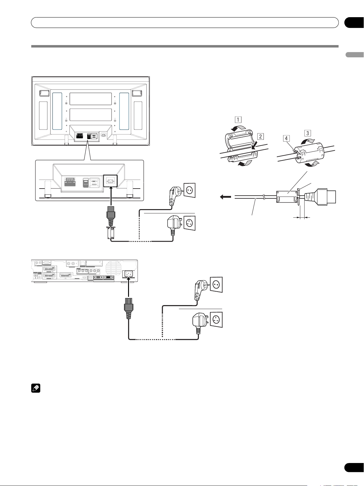
Connecting the power cord
Plasma Display (rear view)
SYSTEM
CABLE
WHITE
BLACK
05
English
Attaching the ferrite core
To help prevent noise, attach the supplied ferrite core to the
connector end of the power cord as shown. Use the supplied
cable tie to prevent the ferrite core from slipping on the
cable.
SYSTEM
CABLE
WHITE
BLACK
Media Receiver (rear view)
IN OUT
SERVICE ONLY
CONTROL
INPUT 1
ANT
i /o link.A
SELECT
INPUT
2 3
INPUT 1
ANT(DIGITAL)
INOUT
OPTICAL
DIGITAL OUT
COMMON INTERFACE
INPUT 2
Y
PB PR
R-AUDIO-L SUB
WOOFER
COMPONENT VIDEO
AUDIO OUTPUT
INPUT 3
HDMI HDMI
BLACK
INPUT 4
SYSTEM CABLE
Europe, except UK
and Eire
To power outlet
AC power cord
As close as possible
Ferrite core
Cable tie
To AC IN
UK and Eire
WHITE
AC IN
Europe, except UK
and Eire
UK and Eire
NOTE
• Disconnect the power cord from the power outlet, Plasma Display and Media Receiver when the system is not going to be used
for a long period of time.
19
En
Page 20

05
SYSTEM
CABLE
WHITE
BLACK
Preparation
Routing cables
Speed clamps and bead bands are supplied for bunching cables. Once properly bunched, follow the steps below to route the
cables.
When the speakers are installed on the sides (rear view)
SYSTEM
CABLE
WHITE
BLACK
Speaker cable
Speed clamp
Attaching speed clamps to the main unit
Attach the speed clamps using the 2 holes marked with
below, depending on your routing system.
SYSTEM
CABLE
WHITE
BLACK
When the speakers are installed at the bottom
Speaker cableSpeed clamp
Cable binder
(supplied with
the stand)*
Attaching and removing speed clamps
Insert [1] into an appropriate hole on the rear of the Plasma
Display and snap [2] into the back of [1] to lock the clamp.
Speed clamps are designed to be difficult to undo once in
place. Please attach them carefully.
Use pliers to twist the clamp 90°, pulling outward. The clamp
may deteriorate over time and become damaged if removed.
Speaker cable
NOTE
• Use the supplied bead bands as necessary.
• For only the PDP-436PE 43" Plasma Display, you can install
the speakers at its bottom.
20
En
Cable binders (supplied
with the stand)*
*Cable binder
Using the cable binders supplied with the stand, put the
speaker and system cables together so that the cables are
invisible from the front. At that time be careful not to apply
any force to the connection sections of the cables.
Speaker cable
Page 21
Preparation
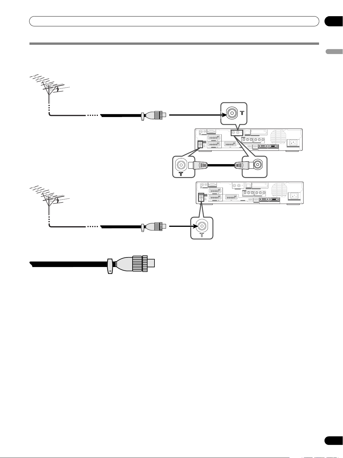
Connecting to an antenna
To enjoy a clearer picture, use an outdoor antenna. The following is a brief explanation of the types of connections that are used
for a coaxial cable.
• For viewing both analogue and
digital broadcasts, connect the
antenna cable to the ANT OUT
terminal (antenna through out)
and ANT (analogue input)
Standard DIN45325 plug (IEC169-2)
75-ohm coaxial cable (round cable)
(commercially available)
IN
IN OUT
SERVICE ONLY
CONTROL
INPUT 1
ANT
i /o link.A
SELECT
INPUT
2 3
INPUT 1
IN OUT
SERVICE ONLY
CONTROL
INPUT 1
ANT
i /o link.A
SELECT
INPUT
2 3
INPUT 1
ANT(DIGITAL)
ANT(DIGITAL)
• For viewing analogue broadcasts only, connect
the 75-ohm coaxial cable (commercially
available) to ANT (analogue input) terminal.
terminal.
• If “Aerial Power” setting is
enabled, use an indoor antenna
with signal amplifier, 5V 30mA.
INOUT
OPTICAL
DIGITAL OUT
COMMON INTERFACE
INPUT 2
Y
PB PR
R-AUDIO-L SUB
OPTICAL
DIGITAL OUT
Y
COMPONENT VIDEO
HDMI HDMI
PBP
HDMI HDMI
AUDIO OUTPUT
INPUT 4
OUT
COMMON INTERFACE
R
AUDIO OUTPUT
INPUT 4
R-AUDIO-L SUB
WOOFER
BLACK
WHITE
SYSTEM CABLE
WOOFER
BLACK
WHITE
SYSTEM CABLE
COMPONENT VIDEO
INPUT 3
INOUT
INPUT 2
INPUT 3
AC IN
AC IN
05
English
Antenna cable (commercially available)
If your outdoor antenna uses a 75-ohm coaxial cable with a standard
DIN45325 plug (IEC169-2), plug it into the antenna terminal at the rear of
the Media Receiver.
21
En
Page 22
05
Preparation
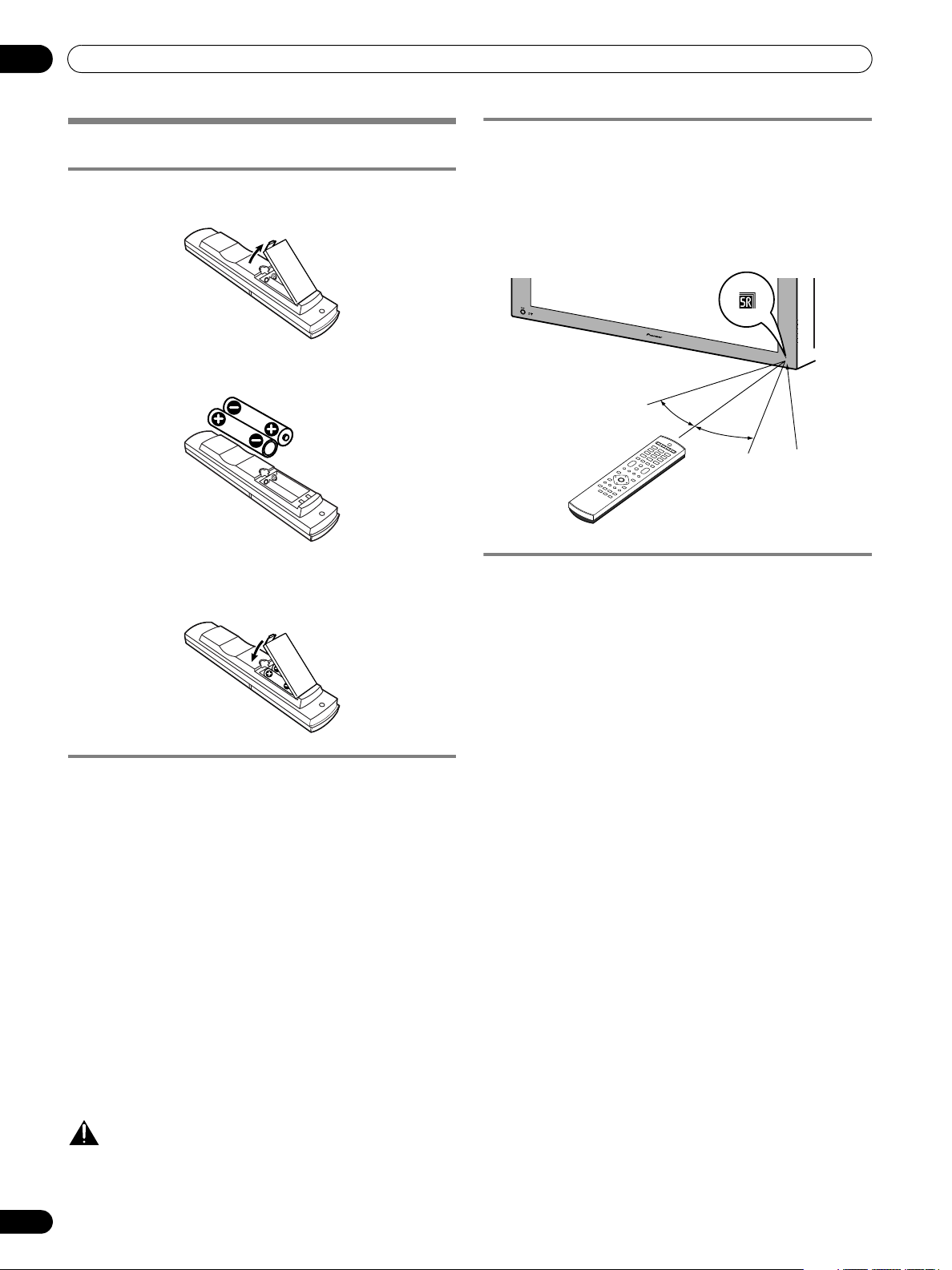
Preparing the remote control unit
Inserting batteries
1 Open the battery cover.
2 Load the supplied two AA size batteries while inserting
their respective negative polarity (–) ends first.
• Place batteries with their terminals corresponding to the
(+) and (–) indicators in the battery compartment.
3 Close the battery cover.
Cautions regarding batteries
Improper use of batteries can result in chemical leakage or
explosion. Be sure to follow the instructions below.
• When you replace the batteries, use manganese or alkaline
ones.
• Place the batteries with their terminals corresponding to the
(+) and (–) indicators.
• Do not mix batteries of different types. Different types of
batteries have different characteristics.
• Do not mix old and new batteries. Mixing old and new
batteries can shorten the life of new batteries or cause
chemical leakage in old batteries.
• Remove batteries as soon as they have worn out. Chemicals
that leak from batteries can cause a rash. If you find any
chemical leakage, wipe thoroughly with a cloth.
• The batteries supplied with this product may have a shorter
life expectancy due to storage conditions.
• If you will not use the remote control unit for an extended
period of time, remove the batteries from it.
Allowed operation range of the remote control
unit
Operate the remote control unit while pointing it toward the
remote control sensor (t) located at the bottom right of the
front panel of the Plasma Display. The distance from the
remote control sensor must be within 7 m and the angle
relative to the sensor must be within 30 degrees in the right,
left, upward, or downward direction.
30º
7 m
30º
Remote control
sensor
Cautions regarding the remote control unit
• Do not expose the remote control unit to shock. In addition,
do not expose the remote control unit to liquids, and do not
place in an area with high humidity.
• Do not install or place the remote control unit under direct
sunlight. The heat may cause deformation of the unit.
• The remote control unit may not work properly if the remote
control sensor of the Plasma Display is under direct sunlight
or strong lighting. In such case, change the angle of the
lighting or Plasma Display, or operate the remote control
unit closer to the remote control sensor.
• When any obstacle exists between the remote control unit
and the remote control sensor, the remote control unit may
not function.
• As the batteries become empty, the remote control unit can
function within a shorter distance from the remote control
sensor. Replace the batteries with new ones early enough.
• The Plasma Display emits very weak infrared rays from its
screen. If you place such equipment operated through
infrared remote control as a VCR nearby, that equipment
may not receive commands from its remote control unit
properly or entirely. If this is the case, place that equipment
at a location far enough from the Plasma Display.
• Depending on the installation environment, infrared rays
from the Plasma Display may not allow this system to
properly receive commands from the remote control unit or
may shorten allowable distances between the remote
control unit and the remote control sensor. The strength of
infrared rays emitted from the screen differs, depending on
images displayed on the screen.
CAUTION
• WHEN DISPOSING OF USED BATTERIES, PLEASE
COMPLY WITH GOVERNMENTAL REGULATIONS OR
ENVIRONMENTAL PUBLIC INSTRUCTION’S RULES
22
En
THAT APPLY IN YOUR COUNTRY/AREA.
Page 23
Watching TV
Watching TV
06
Unless you set up TV channels that you can watch under the
current conditions, you cannot tune in those channels. For the
procedure, see “Setting up TV channels automatically” on page
30.
Turning on/off the power
NOTE
• When the Media Receiver is plugged into a power outlet, it is
placed into the standby mode; the STANDBY indicator on its
front panel should flash red. The Media Receiver stays in the
standby mode unless it is unplugged from the power outlet.
To turn on the system, press POWER on the Plasma Display.
• The POWER ON indicators on the Plasma Display and Media
Receiver light up in blue.
To turn off the system, press a on the remote control unit or
STANDBY/ON on the Media Receiver.
• The Plasma Display and Media Receiver are placed into the
standby mode; their respective STANDBY indicators light up
in red.
• You can then turn on the system again by pressing a or 0 to
9 on the remote control unit or STANDBY/ON on the Media
Receiver. If you press 0 on the remote control unit, images
come from the INPUT 1 source. If you press 1 to 9, TV images
display.
You can also press POWER on the Plasma Display to turn off
the system. However, you cannot then turn on the system
again by pressing the buttons on the remote control unit and
Media Receiver.
NOTE
• Before operating with the remote control unit, make sure to
select the TV mode using its SELECT button. See “Controlling
other equipment using the supplied remote control unit” on
page 69.
• It is recommended not to unplug the Media Receiver from a
power outlet when it is not in use. When in the standby
mode, the Media Receiver automatically receives Electronic
Programme Guide and DTV Auto Update signals.
• When the system is placed into the standby mode, the main
power flow is cut and the system is no longer fully
operational. A minute flow of power feeds the system to
maintain operation readiness.
• If you are not going to use the Plasma Display System for a
long period of time, be sure to remove the power cord from
the power outlet.
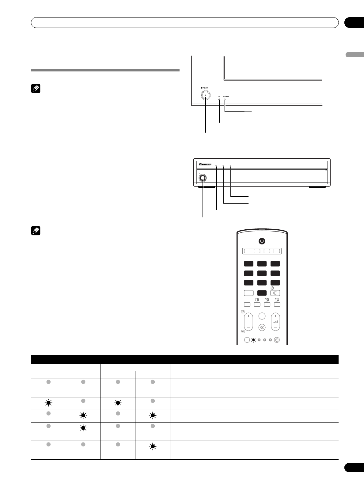
Plasma Display/Media Receiver status indicators
The table below shows the operational status of the Plasma
Display System. You can check the current status of the system
with the indicators on the Plasma Display and Media Receiver.
Plasma Display
POWER ON indicator
POWER
button
Media Receiver
STANDBY/ON
POWER ON indicator
STANDBY/ON
TIMERSTANDBYON
button
STANDBY indicator
TIMER indicator
STANDBY indicator
1
2 3 4
INPUT
1 2 3
4 5 6
7 8 9
PC
INPUT 5
P
SELECT
TV STB
0
TV/DTV
DVD/
DVR
VCR
INFO
SOURCE
English
PULL
OPEN
Indicator Status System Status
Plasma Display Media Receiver
POWER ON STANDBY POWER ON STANDBY
Flashing
Flashing
For other than the above, see “Troubleshooting” on page 76.
The power cords of both the Plasma Display and the Media Receiver have been
disconnected. Or, the power cord of the Plasma Display has been connected but
the POWER button of the Plasma Display is off.
Power to the system is on.
The system is in the standby mode.
The power cord of the Media Receiver has been disconnected.
Power to the Plasma Display is off. Or the power cord of the Plasma Display has
been disconnected.
23
En
Page 24
06
Watching TV
STANDBY/ON
INPUT
1 2 3
4 5 6
7 8 9
PC
INPUT 5
P
SELECT
TV STB
Channel display
STANDARD
Media Receiver
(front view)
TIMERSTANDBYON
INPUT VOLUME CHANNEL
CHANNEL +/–
INFO
0
TV/DTV
DVD/
SOURCE
VCR
DVR
8
AAA
STEREO
10:00
FULL
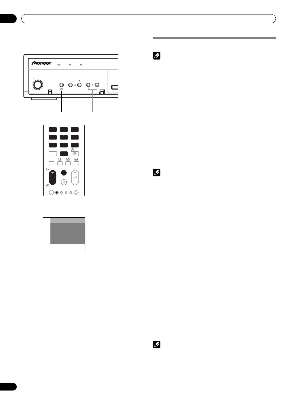
Changing channels
NOTE
• Before operating with the remote control unit, make sure to
select the TV mode using its SELECT button. See “Controlling
other equipment using the supplied remote control unit” on
page 69.
Switching between the TV and
•Press INPUT on the Media Receiver or TV/DTV on the
remote control unit to select the DTV or TV input mode.
Using
P +/P –
on the remote control unit
•Press P + to increase the channel number.
•Press P – to decrease the channel number.
When viewing Teletext information:
•Press P + to increase the page number.
•Press P – to decrease the page number.
• For Teletext, see “Using the Teletext Functions” on pages 74
and 75.
NOTE
• CHANNEL +/– on the Media Receiver operates the same as
P +/P –.
• P +/P – cannot pick up analogue channels that are set to
skip. For Channel Skip for analogue channels, see steps 13
and 14 under “Using Manual Adjust” (page 30).
• When in the DTV mode, P +/P – also cannot pick up digital
channels that are set to skip. For Channel Skip for digital
channels, see “Setting Channel Options” (page 42).
• P +/P – cannot pick up analogue channels that are not
registered as favourites. For analogue favourite channel
registration, see steps 13 and 14 under “Using Manual
Adjust” (page 30).
• When in the DTV mode, P +/P – also cannot pick up digital
channels that are not registered as favourites. For digital
favourite channel registration, see “Setting Channel
Options” (page 42).
DTV
modes
24
En
Using
0 – 9
on the remote control unit
Select channels directly by pressing buttons 0 to 9.
EXAMPLE
• To select channel 2 (1-digit channel), press 2.
• To select channel 12 (2-digit channel), press 1 then 2.
• While in DTV mode, to select channel 123 (3-digit channel),
press 1, 2 then 3.
When viewing Teletext information:
View a page directly which is 3-digit page number from 100 to
899 by pressing buttons 0 to 9. See page 74.
NOTE
• In the standby mode, when you press 0, the power turns on
and images come from the INPUT 1 source. Or, when you
press any button from 1 to 9, TV images display.
Page 25
Watching TV
7 8 9
06
Tuning to your favourite (analogue)
channels
If you have registered your favourite (analogue) channels,
selecting from the registered list may be the easiest way to
tune to those channels.
NOTE
• You can register up to 16 analogue channels as your
favourite channels. For the registration, see steps 13 and 14
under “Using Manual Adjust” (page 30).
1 While watching analogue broadcasts, press ENTER to call
up the Favourite Channel List.
Favourites
01
**********
02
****
03
****
04
****
05
****
06
****
07
****
08
****
2 Select a favourite channel to tune in ( / / / then
ENTER).
• Press RETURN to exit the Favourite Channel List.
09
10
11
12
13
14
15
16
**********
****
****
****
****
****
****
****
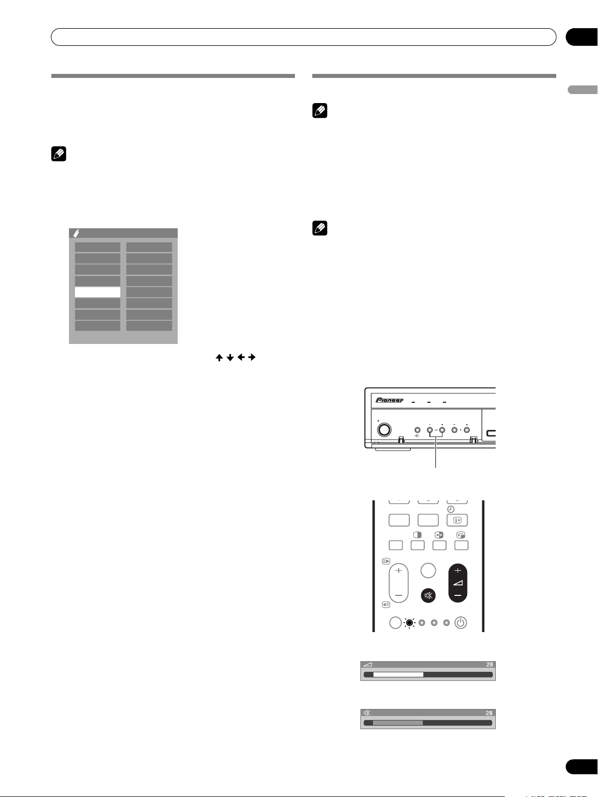
Changing the volume and sound
NOTE
• Before operating with the remote control unit, make sure to
select the TV mode using its SELECT button. See “Controlling
other equipment using the supplied remote control unit” on
page 69.
Using
i
+/
i – on the remote control unit
• To increase the volume, press i +.
–
• To decrease the volume, press i
NOTE
• VOLUME +/– on the Media Receiver operates the same as
i
+/i –
.
Using e on the remote control unit
e mutes the current sound output.
1 Press e.
•“e” appears on the screen.
2 Press e again to cancel the mute mode.
• Pressing i + also cancels the mute mode.
Media Receiver
(front view)
.
TIMERSTANDBYON
English
STANDBY/ON
INPUT VOLUME CHANNEL
VOLUME +/–
DVD /
DVR
VCR
INFO
SOURCE
PC
INPUT 5
P
SELECT
0
TV/DTV
TV STB
Volume adjustment
Muting
25
En
Page 26
06
Watching TV
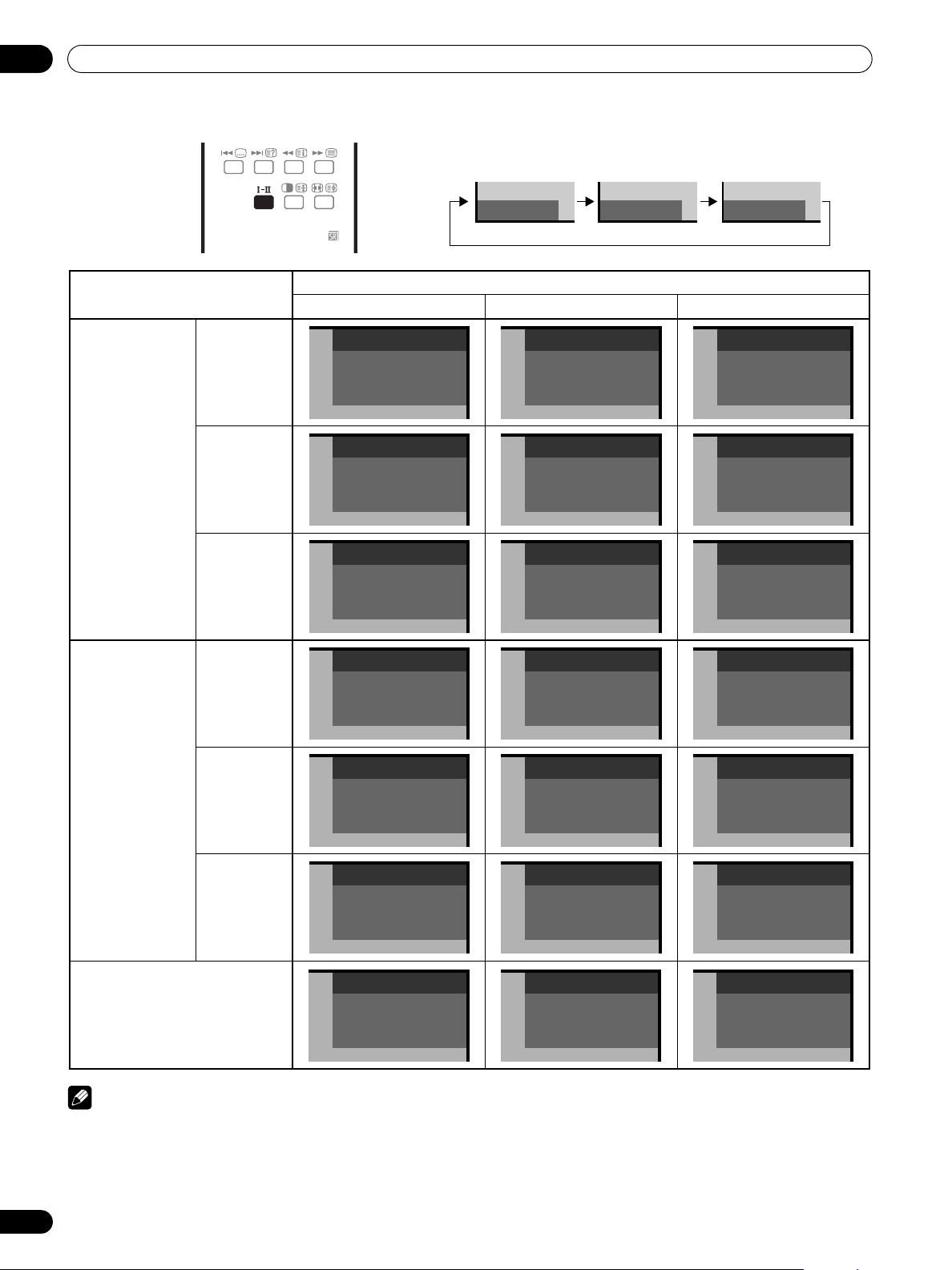
Using
g
on the remote control unit
Each time you press
p mode pp mode MONO mode
g
, MTS toggles as shown below.
NICAM
Broadcasts
DISC
NAVI
Stereo
Bilingual
Monaural
Stereo
DVD HDD
1
AAA
NICAM STEREO
10:00
2
BBB
NICAM p
10:00
3
CCC
NICAM MONO
10:00
4
DDD
STEREO
10:00
pppMONO
Setting
MONOppp
1
AAA
NICAM STEREO
10:00
2
BBB
NICAM pp
10:00
3
CCC
NICAM MONO
10:00
4
DDD
STEREO
10:00
1
AAA
MONO
10:00
2
BBB
MONO
10:00
3
CCC
MONO
10:00
4
DDD
MONO
10:00
A2 Broadcasts
Digital
Broadcasts
Bilingual
Monaural
5
EEE
DUAL p
10:00
6
FFF
MONO
10:00
7
GGG
STEREO
10:00
5
EEE
DUAL pp
10:00
6
FFF
MONO
10:00
7
GGG
STEREO
10:00
MONO
10:00
MONO
10:00
GGG
MONO
10:00
NOTE
• In each of the sound multiplex mode selected using the g button, the display changes depending on broadcasting signals
being received.
• Once the MONO mode is selected, the Plasma Display System sound remains mono even if the system receives a stereo
broadcast. You must switch the mode back to I or II mode if you want to hear stereo sound again.
• Selecting a sound multiplex mode while the input source is INPUT 1 to 5 does not change the type of sound. In this case, sound
26
En
is determined by the video source.
5
EEE
6
FFF
7
Page 27

Watching TV
Use the multiscreen functions
Splitting the screen
Use the following procedure to select 2-screen or picture-inpicture mode.
2-screen
Main screen Sub screen
Picture-in-picture
Main screen Sub screen
INPUT 5
TV/DTV
DISC
P
1 Press c to select the display mode.
• Each time you press c, the display mode is switched
among 2-screen, picture-in-picture, and single-screen.
• In 2-screen or picture-in-picture mode, press to
switch the position of the 2 screens shown.
The left screen (in the 2-screen mode) or the larger
screen (in the picture-in-picture mode) is the active
screen which will be indicated by “z”. The user is
allowed to operate picture and sound.
NAVI
DVD HDD
06
• In picture-in-picture mode, press to move the position
of the small screen anti-clockwise.
English
2 To select the desired input source, press the appropriate
input source button.
• If watching TV programmes, press P +/P – to change the
channel.
NOTE
• The multiscreen function cannot display images from the
same input source at the same time. If you make such an
attempt, a warning message appears.
• The multiscreen function cannot display images from
combinations of two external input sources (Input 1 to 5, PC).
It can display images from the following combinations of
input sources.
- Analogue TV and digital TV
- Analogue TV (or digital TV) and external source
(Input 1 to 5, PC)
• When you press HOME MENU the single-screen mode is
restored and the corresponding menu is displayed.
• When in the 2-screen mode, images displayed on the right
screen may look less fine, depending on the images.
• While in the 2-screen or picture-in-picture mode, the
analogue favourite channel list is not available.While in the
2-screen or picture-in-picture mode, the digital channel list is
not available.
• If you select 1920*1080P@24Hz for the main screen in the
picture-in-picture mode, video images may not be displayed
properly because of the system's capability.
• With headphones connected, you can listen to audio coming
from the sub screen when in the 2-screen or picture-inpicture mode. For more information, see page 37.
• PAL 60 signals are not suited for image display on the Sub
screen.
• In 2-screen mode, press f to change the size of the left
screen.
27
En
Page 28
06
Watching TV
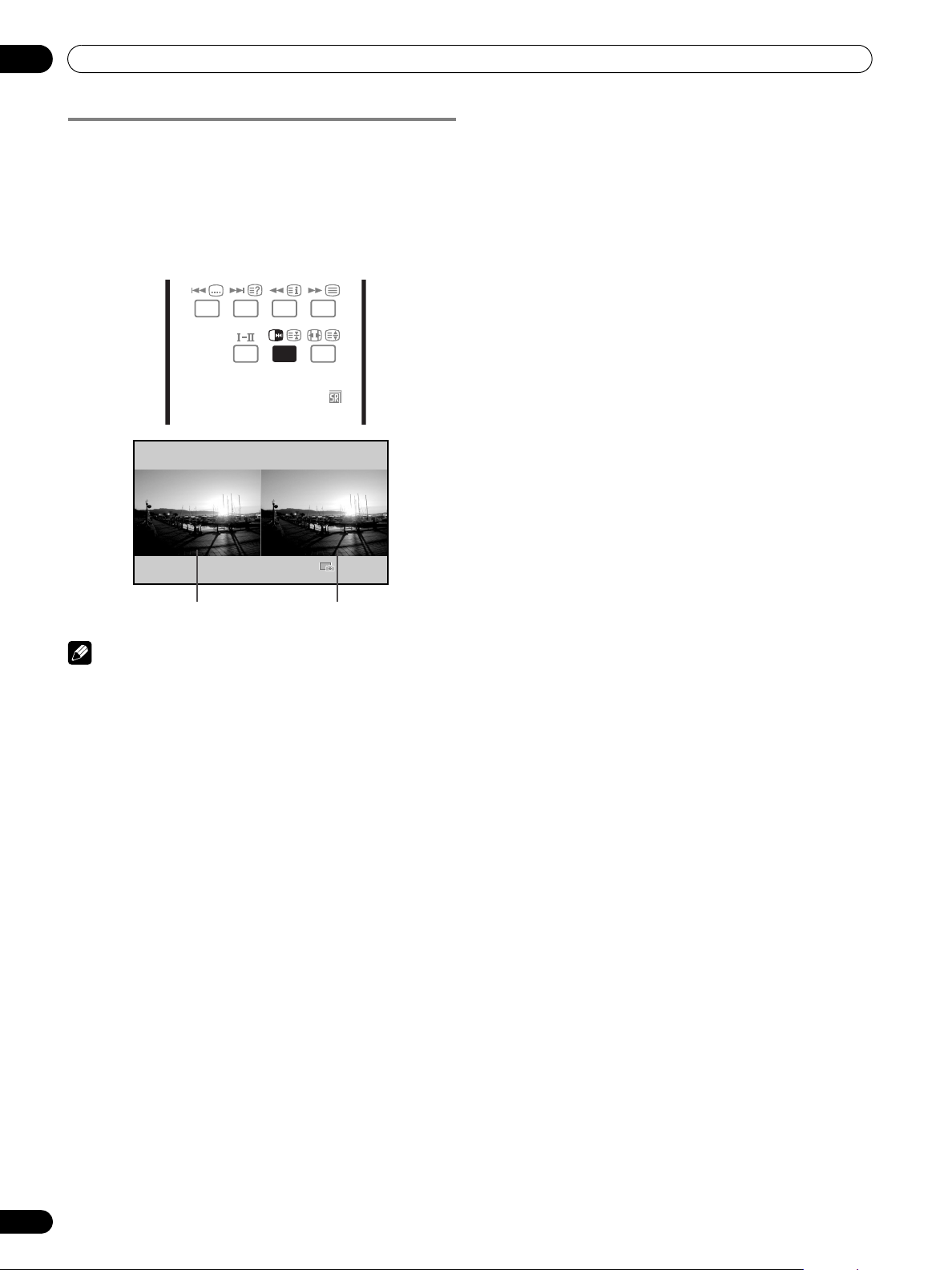
Freezing images
Use the following procedure to capture and freeze one frame
from a moving image that you are watching.
1 Press d.
• A still image appears on the right screen while a moving
image is shown on the left screen.
2 Press d again to cancel the function.
DISC
DVD HDD
NAVI
Normal image
Still image
NOTE
• With the screen split, any image cannot be frozen.
• When this function is not available, a warning message
appears.
• Before operating with the remote control unit, make sure to
select the TV mode using its SELECT button. See “Controlling
other equipment using the supplied remote control unit” on
page 69.
28
En
Page 29
Menu Setup
Menu Setup
07
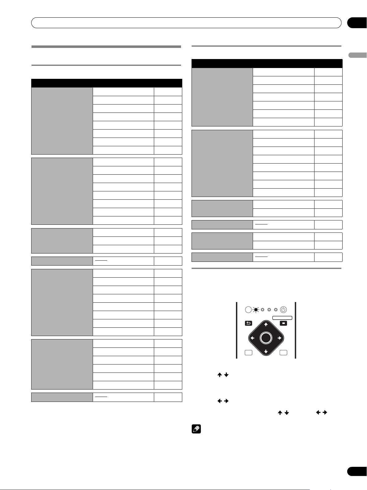
Using the menu
AV mode menus
Home Menu Item Page
Picture AV Selection 33
Contrast 33
Brightness 33
Colour 33
Tint 33
Sharpness 33
Pro Adjust 34
Reset 34
Sound Treble 36
Bass 36
Balance 36
Reset 36
FOCUS 36
Front Surround 37
Headphone Output 37
Sub Volume 37
Power Control Energy Save 38
No Signal off 38
No Operation off 38
Sleep Timer 58
PC mode menus
Home Menu Item Page
Picture AV Selection 33
Contrast 33
Brightness 33
Red 33
Green 33
Blue 33
Reset 34
Sound Treble 36
Bass 36
Balance 36
Reset 36
FOCUS 36
Front Surround 37
Headphone Output 37
Sub Volume 37
Power Control Energy Save 38
Power Management 38
Sleep Timer 58
Option Auto Setup 54
Manual Setup 54
Home Gallery 67 – 69
English
Option Positio n 54
Auto Size 57
4:3 Mode 57
Side Mask 57
HDMI Input 61
Drive Mode 54
Colour System 55
Input Select 55
Setup Auto Installation 30
Analogue TV Setup 30 – 32, 46
DTV Setup 40 – 44, 51
SCART Output 64
Password 58, 59
Language 30
Home Gallery 67 – 69
Menu operations
The following describes the typical procedure for setting up the
menus. For the actual procedures, see the appropriate pages
that describes individual functions.
DVD/
SELECT
TV
STB
RETURN
EXIT EPG
VCR
DVR
HOME MENU
ENTER
DVD TOP MENU / GUIDE
SOURCE
MENU
1 Press HOME MENU.
2 Press / to select a menu item, and then press ENTER.
3 Repeat step 2 until you access the desired submenu item.
• The number of menu layers differs depending on the
menu items.
4 Press / to select an option (or parameter), and then
press ENTER.
• For some menu items, press / instead of / .
5 Press HOME MENU to exit the menu.
NOTE
• You can return to the upper menu levels by pressing
RETURN.
• Before operating with the remote control unit, make sure to
select the TV mode using its SELECT button. See “Controlling
other equipment using the supplied remote control unit” on
page 69.
29
En
Page 30

08
Basic Adjustment Settings
Basic Adjustment Settings
Setting up TV channels automatically
This section describes how to automatically search for and set
up TV channels.
Using Auto Installation
When the Plasma Display System is switched on for the first
time after purchase, the initial auto installation is initiated. You
can automatically set language, country and channels in
successive operations.
1 Select “Language” ( / ).
2 Select a language ( / ).
Auto Installation
Language
Country
Tuner Type
Aerial Power
Installation
• You can select from among 14 languages; English,
German, French, Italian, Spanish, Dutch, Swedish,
Portuguese, Greek, Finnish, Russian, Turkish,
Norwegian, and Danish.
3 Select “Country” ( / ).
4 Select the country ( / ).
5 Select “Tuner Type” ( / ).
6 Select a tuner type ( / ).
• You can select among 3 options; All, Digital, and
Analogue.
7 Select “Aerial Power” ( / ).
• Only selectable when “Digital” or “All” is selected for
“Tuner Type” in step 5. If not go to step 9.
8 Select “On” or “Off” ( / ).
9 Select “Start” ( / then ENTER).
• Auto Installation automatically starts.
• To quit Auto Installation in progress, press RETURN.
English
Austria
All
Off
Start
NOTE
• You can start Auto Installation from the Home menu after
moving to another country, for example. Perform the
following steps 1 to 3 before starting Auto Installation.
➀ Press HOME MENU.
➁ Select “Setup” ( / then ENTER).
➂ Select “Auto Installation” ( / then ENTER).
• The password entry screen appears. Enter your 4-digit
password using buttons 0 – 9.
• If no channel is found, check the antenna connections, and
then retry Auto Installation.
Setting up analogue TV channels
manually
This section describes how to set up analogue TV channels
manually.
Using Manual Adjust
Use Manual Adjust to set up analogue TV channels manually.
1 Press HOME MENU.
2 Select “Setup” ( / then ENTER).
3 Select “Analogue TV Setup” ( / then ENTER).
• The password entry screen appears. Enter your 4-digit
password using buttons 0 – 9. For the password, see
“Using a password” on page 58.
4 Select “Manual Adjust” ( / then ENTER).
5 Select “Programme Entry” ( / ).
Manual Adjust
Programme Entry
Search
System
Colour System
Store
Tuner NR
Child Lock
Decoder
6 Select a programme number ( / ).
• You can select 1 through 99.
7 Select “Search” ( / ).
8 Enter a frequency using buttons 0 – 9 and ENTER.
• You can also press / to enter a frequency.
1
41.75MHz
B/G
Auto
No
On
View
Off
30
En
Manual Adjust
Programme Entry
Search
System
1
41.81MHz
B/G
Page 31

Basic Adjustment Settings
08
9 Select “System” ( / ).
10 Select a sound system ( / ).
• You can select from among “B/G”, “D/K”, “I”, “L”, and
“L’”.
Manual Adjust
Programme Entry
Search
System
1
42.75MHz
B/G
11 Select “Colour System” ( / ).
12 Select a colour system ( / ).
• You can select from among “Auto”, “PAL”, “SECAM”,
and “4.43NTSC”.
System
Colour System
Store
B/G
Auto
No
13 Select “Store” ( / ).
14 Select “Yes”, “Yes (Listed)”, or “No” ( / ).
Colour System
Store
Tuner NR
Auto
Yes
On
3 Select “On” or “Off” ( / ).
Store
Tuner NR
Child Lock
Yes
On
View
4 Press HOME MENU to exit the menu.
NOTE
• This function may not achieve a satisfactory result,
depending on the conditions of broadcasting signals.
• When using a decoder with a decoder terminal selected, this
function may fail to achieve a good result.
Setting Child Lock
Child Lock inhibits selected TV channels from being tuned and
watched.
1 Repeat steps 1 to 6 provided for “Using Manual Adjust”.
After selecting a channel (using Programme Entry),
perform the following steps.
2 Select “Child Lock” ( / ).
3 Select “Block” ( / ).
Tuner NR
Child Lock
Decoder
On
Block
Off
English
Item Description
Ye s You can select the channel using P +/P –.
Yes (L i s t e d ) Select this option to register the channel as
your favourite channel.
You can select the channel using the Favourite
Channel list and P +/P –.
No You cannot select the channel using P +/P –.
• To set up for another channel, repeat steps 6 to 14.
15 Press HOME MENU to exit the menu.
NOTE
• The above procedure transfers and sets the selected channel
information to the connected recording equipment such as
a VCR or DVD recorder (DVR).
• Manual Adjust also allows you to make selections for “Tuner
NR”, “Child Lock”, and “Decoder”. See “Reducing video
noise”, “Setting Child Lock”, and “Selecting a decoder input
terminal”.
Reducing video noise
For the individual channels, you can specify whether the
Plasma Display System should reduce video noise depending
on the levels of broadcasting signals.
1 Repeat steps 1 to 6 provided for “Using Manual Adjust”.
• After selecting a channel (using Programme Entry),
perform the following steps.
2 Select “Tuner NR” ( / ).
• The selection is switched between “View” and “Block”.
4 Press HOME MENU to exit the menu.
Selecting a decoder input terminal
If you have connected a decoder, select a decoder input
terminal (INPUT1).
1 Repeat steps 1 to 6 provided for “Using Manual Adjust”.
After selecting a channel (using Programme Entry), do the
following steps.
2 Select “Decoder” ( / ).
3 Select “INPUT 1” ( / ).
Tuner NR
Child Lock
Decoder
On
Block
INPUT1
4 Press HOME MENU to exit the menu.
NOTE
• With “Off” (factory default) selected, you cannot watch any
images from the decoder.
31
En
Page 32

08
Basic Adjustment Settings
Labelling TV channels
You can name TV channels that you have set up, using up to
five characters. This may help you easily identify the channels
during selections.
1 Press HOME MENU.
2 Select “Setup” ( / then ENTER).
3 Select “Analogue TV Setup” ( / then ENTER).
• The password entry screen appears. Enter your 4-digit
password using buttons 0 – 9.
4 Select “Label” ( / then ENTER).
5 Select “Programme Entry” ( / ).
6 Select a programme number ( / ).
• You can select 1 through 99.
Label
Programme Entry
Label
1
7 Select “Label” ( / then ENTER).
• The name entry screen appears.
8 Select the first character ( / , / then ENTER).
1234567890
A
BCDEFGH I J
KLMNOPQRST
Delete
Space
UVWXYZ, . : ;
&' ()+- * /_@
OK
• The cursor moves to the second character.
9 Repeat step 8 to enter up to five characters.
• To correct entered characters, select [] or [] on the
screen, and then press ENTER. The cursor moves to the
preceding or subsequent character.
• To delete the current character, select [Delete] on the
screen, and then press ENTER.
• To put a space for the current character, select [Space]
on the screen, and then press ENTER.
10 To complete the name entry, press / or / to select
[OK] on the screen, and then press ENTER.
11 Press HOME MENU to exit the menu.
Sort 1/4
19
20
21
22
23
24
25
RRRRR18
SSSSS
TTTTT
UUUUU
VVVVV
WWWWW
XXXXX
YYYYY
IIIII09
JJJJJ
AAAAA01
BBBBB02
CCCCC03
DDDDD04
EEEEE05
FFFFF06
GGGGG07
HHHHH08
10
11
12
13
14
15
16
17
KKKKK
LLLLL
MMMMM
NNNNN
OOOOO
PPPPP
QQQQQ
5 Select a channel to be shifted ( / , / then ENTER).
6 Select a new location ( / , / then ENTER).
• Sorting is executed.
7 Press HOME MENU to exit the menu.
NOTE
• To change a page on the Sort screen in step 6, select ▲/▼ on
the screen with / to select a page, and then press
• The above procedure transfers and sets only the shifted
channel information to recording equipment such as a VCR
or DVD recorder (DVR).
ENTER
Clock setting
Use the following procedure to set the time correctly.
1 Press HOME MENU.
2 Select “Setup” ( / then ENTER).
3 Select “Analogue TV Setup” ( / then ENTER).
• The password entry screen appears. Enter your 4-digit
password using buttons 0 – 9.
4 Select “Clock” ( / then ENTER).
5
Select a TV channel to be used for auto clock setting (/).
Clock
02/07/2004 FRI 0:00
Clock Set Programme
1 ABCDE
6 Press HOME MENU to exit the menu.
NOTE
• If the system fails to set the date and time through the
selected TV channel, the “Time & Date” entry screen appears.
Set the correct, current time.
• The system obtains and displays time by adding Universal
Coordinated Time (UTC) and Local Time Offset (LTO) data
received with broadcasting signals. If the system fails to
display a correct time, check with your local broadcasting
station.
.
NOTE
• The above procedure transfers and sets the selected channel
information to the connected recording equipment such as
a VCR or DVD recorder (DVR).
Sorting preset TV channels
Use the following procedure to change the sequence of the
preset TV programmes.
1 Press HOME MENU.
2 Select “Setup” ( / then ENTER).
3 Select “Analogue TV Setup” ( / then ENTER).
• The password entry screen appears. Enter your 4-digit
password using buttons 0 – 9.
4 Select “Sort” ( / then ENTER).
• The sort screen appears.
32
En
Language setting
You can select the language to be used for on-screen display
such as menus and instructions, from among 14 languages;
English, German, French, Italian, Spanish, Dutch, Swedish,
Portuguese, Greek, Finnish, Russian, Turkish, Norwegian, and
Danish.
For the language to be used in the TELETEXT mode, you can
select from among West Europe, East Europe, Greece/Turkey,
Russia, and Arabia.
1. Press HOME MENU.
2 Select “Setup” ( / then ENTER).
3 Select “Language” ( / then ENTER).
4 Select “Menu” ( / ).
Page 33

Basic Adjustment Settings
08
5 Select a language ( / ).
Language
Menu
Teletext
English
West Europe
6 Select “Teletext” ( / ).
7 Select a language ( / ).
8 Press HOME MENU to exit the menu.
AV Selection
Select from the five viewing options, depending on the current
environment (e.g., room brightness), the type of the current TV
programme, or the type of images input from external
equipment.
1 Press HOME MENU.
2 Select “Picture” ( / then ENTER).
3 Select “AV Selection” ( / then ENTER).
4 Select the desired option ( / then ENTER).
AV Selection
STANDARD
DYNAMIC
MOVIE
GAME
USER
For AV source
Item Description
STANDARD For a highly defined image in a normally bright
DYNAMIC For a very sharp image with the maximum
MOVIE For a movie
GAME Lowers image brightness for easier viewing
USER Allows the user to customize settings as
For PC source
Item Description
STANDARD
(factory default)
USER Allows the user to customize settings as
room
This selection is shared by an external input
and TV input sources.
contrast
This mode does not allow manual image quality
adjustment.
This selection is shared by an external input
and TV input sources.
This selection is shared by an external input
and TV input sources.
This selection is shared by an external input
and TV input sources.
desired. You can set the mode for each input
source.
For a highly defined image in a normally bright
room
desired. You can set the mode for each input
source.
NOTE
• If you have selected “DYNAMIC”, you cannot select
“Contrast”, “Brightness”, “Colour”, “Tint”, “Sharpness”, “Pro
Adjust”, and “Reset”; these menu items are dimmed.
Basic picture adjustments
Adjust the picture to your preference for the chosen AV
Selection option (except DYNAMIC).
1 Press HOME MENU.
2 Select “Picture” ( / then ENTER).
3 Select an item to be adjusted ( / then ENTER).
Picture
AV Selection
Contrast
Brightness
Colour
Tint
Sharpness
Pro Adjust
Reset
For PC source or Home Gallery, the following screen appears.
Picture
AV Selection
Contrast
Brightness
Red
Green
Blue
Reset
4 Select the desired level ( / ).
Contrast
• When an adjustment screen is in display, you can also
change the item to be adjusted, by pressing / .
5 Press HOME MENU to exit the menu.
For AV source
Item
Contrast For less contrast For more contrast
Brightness For less brightness For more brightness
Colour For less colour intensity For more colour intensity
Tint Skin tones become
Sharpness For less sharpness For more sharpness
button button
purplish
STANDARD
40
0
0
0
0
STANDARD
40
0
0
0
0
40
Skin tones become
greenish
English
5 Press HOME MENU to exit the menu.
33
En
Page 34

08
Basic Adjustment Settings
For PC source
Item
Contrast For less contrast For more contrast
Brightness For less brightness For more brightness
Red For weaker red For stronger red
Green For weaker green For stronger green
Blue For weaker blue For stronger blue
button button
NOTE
• To perform advanced picture adjustments, select “Pro
Adjust” in step 3 and then press ENTER. For the subsequent
procedures, see “Advanced picture adjustments”.
• To restore the factory defaults for all items, press / to
select “Reset” in step 3, and then press ENTER. A
confirmation screen appears. Press / to select “Yes”, and
then press ENTER.
Advanced picture adjustments
The Plasma Display System provides various advanced
functions for optimising the picture quality. For details on
these functions, see the tables.
Using PureCinema
1 Press HOME MENU.
2 Select “Picture” ( / then ENTER).
3 Select “Pro Adjust” ( / then ENTER).
4 Select “PureCinema” ( / then ENTER).
5 Select the desired parameter ( / then ENTER).
• For the selectable parameters, see the table.
PureCinema
Automatically detects a film-based source (originally encoded at 24
frames/second), analyses it, then recreates each still film frame for highdefinition picture quality.
Selections Off Deactivates the PureCinema.
Standard Produces smooth and vivid moving
ADV Produces smooth and quality moving
NOTE
• “Standard” is not selectable when 480p or 720p@60Hz
signals are input.
• “ADV” is not selectable when PAL, SECAM, 576i, or
1080i@50Hz signals are input.
• Neither “Standard” nor “ADV” is selectable when 576p,
720p@50Hz, or 1080p@24Hz signals are input.
images (film specific) by automatically
detecting recorded image information
when displaying DVD or high-definition
images (e.g., movies) having 24 frames
per second.
images (as shown on theatre screens) by
converting to 72 Hz when displaying DVD
images (e.g., movies) having 24 frames
per second.
Using Colour Temp
1 Press HOME MENU.
2 Select “Picture” ( / then ENTER).
3 Select “Pro Adjust” ( / then ENTER).
4 Select “Colour Detail” ( / then ENTER).
5 Select “Colour Temp” ( / then ENTER).
6 Select the desired parameter ( / then ENTER).
• If you have selected a desired parameter in this step,
skip steps 7 and 8.
• You may rather want to perform fine adjustment. To do
this, select “Manual” first and then press and hold
ENTER for more than three seconds. The manual
adjustment screen appears. Then go to step 7.
Colour Temp
Adjusts the colour temperature, resulting in a better white balance.
Selections High White with bluish tone
Mid-High Intermediate tone between High and Mid
Mid Natural tone
Mid-Low Intermediate tone between Mid and Low
Low White with reddish tone
Manual Colour temperature adjusted to your
preference
7 Select an item to be adjusted ( / then ENTER).
8 Select the desired level ( / ).
Item
R High Fine a djustment
G High For weaker green For stronger green
B High For weaker blue For stronger blue
R Low Fine adjustment
G Low For weaker green For stronger green
B Low For weaker blue For stronger blue
for bright
portions
for dark
portions
• To perform adjustment for another item, press RETURN,
and then repeat steps 7 and 8.
• You may press / to immediately change an item to
be adjusted.
button button
For weaker red For stronger red
For weaker red For stronger red
9 Press HOME MENU to exit the menu.
Using CTI
1 Press HOME MENU.
2 Select “Picture” ( / then ENTER).
3 Select “Pro Adjust” ( / then ENTER).
4 Select “Colour Detail” ( / then ENTER).
5 Select “CTI” ( / then ENTER).
34
En
Page 35

Basic Adjustment Settings
08
6 Select the desired parameter ( / then ENTER).
CTI
Provides images with clearer colour contours. The CTI stands for Colour
Transient Improvement.
Selections Off Deactivates the CTI.
On Activates the CTI.
7 Press HOME MENU to exit the menu.
Using Colour Management
1 Press HOME MENU.
2 Select “Picture” ( / then ENTER).
3 Select “Pro Adjust” ( / then ENTER).
4 Select “Colour Detail” ( / then ENTER).
5 Select “Colour Management” ( / then ENTER).
6 Select an item to be adjusted ( / then ENTER).
Colour Management
R
Y
G
C
B
M
0
0
0
0
0
0
Eliminating noise from images
1 Press HOME MENU.
2 Select “Picture” ( / then ENTER).
3 Select “Pro Adjust” ( / then ENTER).
4 Select “NR” ( / then ENTER).
5 Select an item to be adjusted ( / then ENTER).
• You can select “DNR” or “MPEG NR”.
6 Select the desired parameter ( / then ENTER).
DNR
Eliminates video noise for clean crisp images. The DNR stands for Digital
Noise Reduction.
Selections Off Deactivates the DNR.
High Enhanced DNR
Mid Standard DNR
Low Moderate DNR
MPEG NR
Eliminates mosquito noise from video images when a digital TV channel is
watched or a DVD is played, resulting in noise-free images.
Selections Off Deactivates the MPEG NR.
High Enhanced MPEG NR
Mid Standard MPEG NR
Low Moderate MPEG NR
7 Press HOME MENU to exit the menu.
English
7 Select the desired level ( / ).
Item
R Closer to magenta Closer to yellow
Y Closer to red Closer to green
G Closer to yellow Closer to cyan
C Closer to green Closer to blue
B Closer to cyan Closer to magenta
M Closer to blue Closer to red
• To perform adjustment for another item, press RETURN,
and then repeat steps 6 and 7.
• You may press / to immediately change an item to
be adjusted.
button button
8 Press HOME MENU to exit the menu.
Using the Dynamic Range Expander (DRE)
functions
1 Press HOME MENU.
2 Select “Picture” ( / then ENTER).
3 Select “Pro Adjust” ( / then ENTER).
4 Select “DRE” ( / then ENTER).
5 Select an item to be adjusted ( / then ENTER).
• You can select “Dynamic Contrast”, “Black Level”, “ACL”
or “Gamma”.
6 Select the desired parameter ( / then ENTER).
Dynamic Contrast
Emphasises the contrast on images so that the difference between
brightness and darkness becomes more distinct.
Selections Off Deactivates the Dynamic Contrast.
High Enhanced Dynamic Contrast
Mid Standard Dynamic Contrast
Low Moderate Dynamic Contrast
Black Level
Emphasises dark portion on images so that the difference between
brightness and darkness becomes more distinct.
Selections Off Deactivates the Black Level.
On Activates the Black Level.
35
En
Page 36

08
Basic Adjustment Settings
ACL
Performs such compensation that results in the optimum contrast
characteristics for images.
Selections Off Deactivates the ACL.
On Activates the ACL.
Gamma
Adjusts the gamma characteristics (image gradation characteristics).
Selections 1 Selects gamma characteristics 1.
2 Selects gamma characteristics 2.
3 Selects gamma characteristics 3.
7 Press HOME MENU to exit the menu.
Using the 3DYC and I-P Mode
1 Press HOME MENU.
2 Select “Picture” ( / then ENTER).
3 Select “Pro Adjust” ( / then ENTER).
4 Select “Others” ( / then ENTER).
5 Select an item to be adjusted ( / then ENTER).
• You can select “3DYC” or “I-P Mode”.
6 Select the desired parameter ( / then ENTER).
3DYC
Optimises characteristics for separating brightness signals and colour
signals. This works for both video and still images.
Selections Off Deactivates the 3DYC.
High Enhanced 3DYC
Mid Standard 3DYC
Low Moderate 3DYC
I-P Mode
Perform optimum conversion from interlace signals to progressive
signals. This works for both video and still images.
Selections 1 Optimum for video images
2 Standard setting
3 Optimum for still images
7 Press HOME MENU to exit the menu.
NOTE
• For the 3DYC, the individual parameters are selectable only
when:
You have selected INPUT 1, 2, or 3 as the input source and
“Video” as the input signal type (page 55); or
You have selected INPUT 5 as the input source without a
S-Video cable in connection; or
You have selected the analog tuner.
• For the I-P Mode, the individual parameters are not
selectable for the following input signals:
480p, 720p@60Hz, 576p, 720p@50Hz, 1080p@24Hz
Sound adjustments
You can adjust the sound quality to your preference with the
following settings.
Adjust the sound to your preference for the chosen AV
Selection option. See page 33.
1 Press HOME MENU.
2 Select “Sound” ( / then ENTER).
3 Select an item to be adjusted ( / ).
4 Select the desired level ( / ).
Sound STANDARD
Treble
Bass
Balance
Reset
FOCUS
Front Surround
Headphone Output
Sub Volume
Item
Tre bl e For weaker treble For stronger treble
Bass For weaker bass For stronger bass
Balance Decreases audio from the
button button
right speaker.
5 Press HOME MENU to exit the menu.
NOTE
• To restore the factory defaults for all items, press / to
select “Reset” in step 3, and then press ENTER. A
confirmation screen appears. Press / to select “Yes”, and
then press ENTER.
• You cannot adjust the sound quality for listening with
phones.
• If you perform sound adjustments with phones connected,
the new settings will become effective for sound from the
speakers after the phones are disconnected.
FOCUS
This shifts the sound coming direction (sound images) upward
and produces clear sound contours.
1 Press HOME MENU.
2 Select “Sound” ( / then ENTER).
3 Select “FOCUS” ( / ).
4 Select the desired parameter ( / ).
Reset
FOCUS
Front Surround
2
0
0
Off
Off
Main
15
Decreases audio from the
left speaker.
Off
Off
36
En
Page 37

Basic Adjustment Settings
08
Item Description
Off
(factory default)
On Activates the FOCUS.
Deactivates the FOCUS.
5 Press HOME MENU to exit the menu.
NOTE
• The effect of this function differs depending on signals.
• You cannot set up the sound field for listening with phones.
• If you set up the sound field with phones connected, the new
setting will become effective for sound from the speakers
after the phones are disconnected.
Front Surround
This provides three-dimensional sound effects and/or deep,
rich bass.
1 Press HOME MENU.
2 Select “Sound” ( / then ENTER).
3 Select “Front Surround” ( / ).
4 Select the desired parameter ( / ).
Item Description
Off Deactivates both the SRS and TruBass.
SRS Reproduces highly effective three-dimensional
TruBass
(factory default)
TruBass + SRS Provides both TruBass and SRS effects.
sound.
Provides deep, rich bass using a new
technology.
5 Press HOME MENU to exit the menu.
NOTE
• (WOW) designates a status where the FOCUS is on
and TruBass + SRS has been selected for Front Surround.
• is a trademark of SRS Labs, Inc.
• WOW technology is incorporated under license from SRS
Labs, Inc.
• The effect of this function differs depending on signals.
• You cannot set up the sound field for listening with phones.
• If you set up the sound field with phones connected, the new
setting will become effective for sound from the speakers
after the phones are disconnected.
Listening to audio from the sub screen
using headphones
With headphones connected, you can listen to audio coming
from the sub screen when in the 2-screen or picture-in-picture
mode; audio coming from the main screen is output from the
speakers. To use this function, follow the procedure below.
1 Press HOME MENU.
2 Select “Sound” ( / then ENTER).
3 Select “Headphone Output” ( / ).
4 Select the desired parameter ( / ).
Front Surround
Headphone Output
Sub Volume
Item Description
Main Audio coming from the main screen is output
Sub
from the PHONES output terminal.
When in the 2-screen or picture-in-picture mode,
audio coming from the sub screen is output
from the PHONES output terminal.
5 Select “Sub Volume” ( / ).
6 Select the desired volume level ( / ).
Front Surround
Headphone Output
Sub Volume
7 Press HOME MENU to exit the menu.
NOTE
• To adjust the volume for headphones after selecting “Sub”,
always use the menu item (shown in the procedure) no
matter whether the screen is in the single, 2-screen, or
picture-in-picture mode. When the screen is in the single
mode with “Sub” selected, audio coming from the screen is
output from speakers even with headphones connected.
• Audio from a connected subwoofer is muted when you have
selected "Sub" for "Headphone Output" and connected
headphones.
Off
Main
15
Off
Sub
15
English
37
En
Page 38

08
Basic Adjustment Settings
Power Control
Power Control provides convenient functions for power saving.
Energy Save
You may use one of the three Energy Save modes to save power
consumption.
1 Press HOME MENU.
2 Select “Power Control” ( / then ENTER).
3 Select “Energy Save” ( / then ENTER).
4 Select “Save 1”,”Save 2”, or “Picture Off” ( / then
ENTER).
Item Description
Standard Does not decrease the picture brightness.
Save1 Slightly lowers power consumption while
Save2 Decreases the picture brightness and lowers
Picture Off Deactivates the screen to save power. To restore
5 Press HOME MENU to exit the menu.
NOTE
• You can also select this function using the Home menu
when the input source is a PC.
No Signal off (AV mode only)
The system will be automatically placed into the standby mode
if no signal is received for 15 minutes.
1 Press HOME MENU.
2 Select “Power Control” ( / then ENTER).
3 Select “No Signal off” ( / then ENTER).
4 Select ”Enable” ( / then ENTER).
Item Description
Disable
(factory default)
Enable Places the system into the standby mode if no
5 Press HOME MENU to exit the menu.
NOTE
• Five minutes before the system is placed into the standby
mode, a message appears every minute.
• The system may not be placed into the standby mode when
noise signals are present at the Media Receiver after a TV
programme finishes.
slightly suppressing the brightness drop level.
power consumption.
the screen display, press any button other than
i +/i – and e.
This setting is not memorised by the system.
Does not place the system into the standby
mode.
signal is received for 15 minutes.
No Operation off (AV mode only)
The system will be automatically placed into the standby mode
when no operation is performed for three hours.
1 Press HOME MENU.
2 Select “Power Control” ( / then ENTER).
3 Select “No Operation off” ( / then ENTER).
4 Select “Enable” ( / then ENTER).
Item Description
Disable
(factory default)
Enable Places the system into the standby mode if no
Does not place the system into the standby
mode.
operation is performed for three hours.
5 Press HOME MENU to exit the menu.
NOTE
• Five minutes before the system is placed into the standby
mode, a message appears every minute.
Power Management (PC mode only)
The system will be automatically placed into the standby mode
when no signal is received from the personal computer.
1 Press HOME MENU.
2 Select “Power Control” ( / then ENTER).
3 Select “Power Management” ( / then ENTER).
4 Select “Mode 1” or “Mode 2” ( / then ENTER).
Item Description
Off
(factory default)
Mode1 • Places the system into the standby mode
Mode2
No power management
when no signal is received from the personal
computer for eight minutes.
• Even when you start using the computer and
a signal is received again, the system stays
off.
• The system is switched on again by pressing
STANDBY/ON on the Media Receiver or TV
a on the remote control unit.
•Places the system into the standby mode
when no signal is received from the personal
computer for eight seconds.
• When you start using the computer and a
signal is input again, the system is switched
on.
• The system is switched on again by pressing
STANDBY/ON on the Media Receiver or TV
a on the remote control
unit.
5 Press HOME MENU to exit the menu.
38
En
Page 39

Enjoying DTV broadcasts
Enjoying DTV broadcasts
09
Watching DTV programmes
Digital TV (DTV) not only replaces the conventional analogue TV
channels, but also provides more channels, clearer picture
quality, and various types of useful information. It also provides
various features, including subtitling and multiple audio
tracks.
NOTE
• When executing Auto Installation (page 30), make sure to
select “Digital” or “All” as the tuner type.
• Selecting the DTV mode when no channels yet searched will
only display “DTV Setup” screen with only the item
“Installation” selectable.
• While in the DTV mode, press m to display the Teletext
screen (except in UK).
Changing channels
1 Press TV/DTV to select the DTV mode.
2 Press ENTER to call up the Channel List screen.
001
************
002
************
003
******
004
************
005
****
006
******
3 Select a channel ( / then ENTER).
• You can also select channels by pressing buttons 0 to 9
or P +/P – on the remote control unit.
NOTE
• While in DTV mode, press 001 to access channel 1 (1-digit
channel) quickly. You can, however, select the channel 1 by
pressing 01 or 1 but have to wait for 2 seconds since the last
digit input. The same applies for 2-digit channels.
• P +/P – cannot pick up channels that are set to skip or not
registered as favourites (with the Favourite function set to
“On”. For favourite channels, see page 25.).
• If the channel is locked, you must enter the correct password
each time (see page 58 ).
• While receiving DTV radio channels, the screen saver
automatically starts when no operation is done for 3
minutes.
Viewing a channel banner
A channel banner shows programme names, start/end time of
programmes and other channel information.
1 Press TV/DTV to select the DTV mode.
2 Press p
• A channel banner appears.
• To display information about other channels, press /.
• To tune into the channel selected on the banner, press
• The channel banner also displays icons for Favourites
• To quit banner display, press EXIT.
.
001
Now
Next
************
********************
*************
Wed.30.Apr 12:46
11:30
12:00
12:30
12:00--
ENTER.
(), Subtitles ([) and Teletext (m) if they apply to the
selected channel.
3 To view more detailed programme information, press p
again.
Now
************************
12:0011:30 -
More...
• To switch between Now and Next programme
information, press / .
• To display detailed information about other channels,
press / .
• To tune into the channel selected on the banner, press
ENTER.
• To quit display of detailed information, press RETURN.
• To quit display of all the banners, press EXIT.
• If the banner contains further information, “More ...” is
displayed. Press the BLUE button to view the entire
information.
NOTE
• Banner information is updated every minute.
• Some programmes may not provide detailed programme
information.
• Due to inaccurate information provided by the broadcaster,
some icons may appear or be absent in error.
Viewing subtitles
When in the DTV mode, press [ to turn subtitles on and off.
English
Subtitles On
NOTE
• When a programme is recorded with this function on,
subtitles are also recorded.
39
En
Page 40

09
Enjoying DTV broadcasts
Reconfiguring the DTV channel settings
This section describes how to reconfigure the DTV channel
settings after setting up DTV channels using Auto Installation
(page 30). You can select “DTV Setup” only when watching DTV
channels.
Reselecting a country
1 Press HOME MENU.
2 Select “Setup” ( / then ENTER).
3 Select “DTV Setup” ( / then ENTER).
4 Select “Installation” ( / then ENTER).
• The password entry screen appears. Enter your 4-digit
password using buttons 0 – 9.
5 Select “Country” ( / ).
6 Select a country ( / ).
Installation
Aerial Power
Country
Add New Channels
Replace Existing Channels
Signal Check
Restore System Defaults
NOTE
• The password entry screen does not appear if you have
disabled the password function. For details, see “Using a
password (AV mode only)” on page 58.
• You can select “DTV Setup” only when watching DTV
channels.
Off
Germany
5 Select “Replace Existing Channels” ( / then ENTER).
• The system first erases all channel information and then
starts channel search.
Replace Existing Channels
Search Information
Existing Channels 04
New Channels Found
Progress
20
30%
Found Channels
001
************
002
************
003
******
004
************
• To quit a channel search in progress, press HOME MENU.
NOTE
• To complete “Replace Existing Channels”, there must be
more than 1 hour at least left to the next preset recording or
preset Auto Update time.
• The password entry screen does not appear if you have
disabled the password function. For details, see “Using a
password (AV mode only)” on page 58.
• You can select “DTV Setup” only when watching DTV
channels.
Adding new channels
Use the following procedure to search and register new
channels with the current DTV channel setups saved.
1 Press HOME MENU.
2 Select “Setup” ( / then ENTER).
3 Select “DTV Setup” ( / then ENTER).
4 Select “Installation” ( / then ENTER).
• The password entry screen appears. Enter your 4-digit
password using buttons 0 – 9.
5 Select “Add New Channels” ( / then ENTER).
Replacing the existing channels
The following procedure discards the current DTV channel
setups and searches for receivable channels to redo the
channel setups.
1 Press HOME MENU.
2 Select “Setup” ( / then ENTER).
3 Select “DTV Setup” ( / then ENTER).
4 Select “Installation” ( / then ENTER).
• The password entry screen appears. Enter your 4-digit
password using buttons 0 – 9.
40
En
Installation
Aerial Power
Country
Add New Channels
Replace Existing Channels
Signal Check
Restore System Defaults
Off
Germany
• Channel search automatically starts. If any new channel
is found, it is automatically registered on the Media
Receiver.
Page 41

Enjoying DTV broadcasts
09
Add New Channels
20
30%
Found Channels
001
************
002
************
003
******
004
************
Search Information
Existing Channels 04
New Channels Found
Progress
• To quit a channel search in progress, press HOME
MENU.
NOTE
• The password entry screen does not appear if you have
disabled the password function. For details, see “Using a
password (AV mode only)” on page 58.
• You can select “DTV Setup” only when watching DTV
channels.
Checking signal strength
You can check the signal strength and signal quality of each TV
channel.
1 Repeat steps 1 to 4 provided for “Adding New Channels”.
2 Select “Signal Check” ( / then ENTER).
3 Select “RF Channel” ( / then ENTER).
4 Select the channel to be checked ( / ).
Signal Check
RF Channel
Add New Channels
Signal Strength
0 25 50 75 100
Signal Quality
77%
:
100% Good
:
• Use “Add New Channels” function here to add channels
within the selected RF channel (receiving frequency).
21
3 Select “On” or “Off” ( / ).
Installation
Aerial Power
Country
Add New Channels
Replace Existing Channels
Signal Check
Restore System Defaults
Off
Germany
NOTE
• You can select “DTV Setup” only when watching DTV
channels.
Restoring the system defaults
Use this function only when you wish to reset all the DTV
settings to the factory defaults.
1 Press HOME MENU.
2 Select “Setup” ( / then ENTER).
3 Select “DTV Setup” ( / then ENTER).
4 Select “Installation” ( / then ENTER).
• The password entry screen appears. Enter your 4-digit
password using buttons 0 – 9.
5 Select “Restore System Defaults” ( / then ENTER).
• A confirmation screen appears.
6 With “OK” pressed, the system restores the factory
defaults. Then Auto Installation is initiated automatically.
NOTE
• The password entry screen does not appear if you have
disabled the password function. For details, see “Using a
password (AV mode only)” on page 58.
• You can select “DTV Setup” only when watching DTV
channels.
English
NOTE
• You can select “DTV Setup” only when watching DTV
channels.
Switching on/off the power to the antenna
Use the following procedure to switch on or off the power to the
antenna connected with the DTV antenna terminal.
1 Repeat steps 1 to 4 provided for “Adding New Channels”.
2 Select “Aerial Power” ( / ).
41
En
Page 42

09
Enjoying DTV broadcasts
Customizing channel related settings
This section describes how to customize various channel
related settings. These settings include favourite channel
registration, Channel Skip, and Channel Lock.
Setting Channel Options
Use the following procedure to select individual channels and
switch on the Favourite, Channel Skip, or Channel Lock for the
channels.
1 Press HOME MENU.
2 Select “Setup” ( / then ENTER).
3 Select “DTV Setup” ( / then ENTER).
4 Select “Channel Management” ( / then ENTER).
• The password entry screen appears. Enter your 4-digit
password using buttons 0 – 9.
5 Select “Channel Options” ( / then ENTER).
• The Channel options screen with a list of registered
channels appears.
Channel Options
Channel Skip
001 ∗∗∗ ∗∗∗
002 ∗∗∗ ∗∗∗
007 ∗∗∗ ∗∗∗∗∗
030 ∗∗∗∗ ∗∗∗∗∗∗∗
040 ∗∗∗ ∗∗∗∗ ∗∗
051 ∗∗∗ ∗
800 ∗∗∗ ∗∗∗∗∗∗∗∗∗∗
6 Select an individual channel (/// then ENTER to
select on/off).
• Select “On” for Favourites if you want the channel to be
registered as your favourite (digital) channels. Selecting
from the registered list may be the easiest way to tune to
those channels.
• Select “On” for Channel Skip if you want the channel to
be skipped when operating P +/P – on the remote
control unit or CHANNEL +/– on the Media Receiver.
• Select “On” for Channel Lock if you want the channel not
to be tuned without password entry.
7 After the setting is complete, make sure to complete the
following steps.
• If you have registered any channel as your favourite one,
see “Enabling Favourite Channels” and activate the
Favourites function.
• If you have selected any channel for Channel Lock, set
“Using a password (AV mode only) on page 58 and set
an appropriate 4-digit password.
Activating the Favourites function
Make sure to activate this function after favourite channels are
registered.
1 Repeat steps 1 to 4 provided for “Setting Channel
Options”.
Channel Management
Favourites
Auto Skip
Child Lock
Channel Options
Channel Sort
Off
Off
Off
2 Select “Favourites” ( / ).
3 Select “On” ( / ).
• With favourite channels registered, you can select them
using P +/P – on the remote control unit or CHANNEL +/
– on the Media Receiver.
NOTE
• You can select “DTV Setup” only when watching DTV
channels.
Activating the Auto Skip
This function lets you skip group of services, such as radio and
text data services.
1 Repeat steps 1 to 4 provided for “Setting Channel
Options”.
2 Select “Auto Skip” ( / ).
Channel Management
Favourites
Auto Skip
Child Lock
Channel Options
Channel Sort
Off
Off
Off
3 Select a channel to skip ( / ).
• You can select from among “Off”, “Radio”, “Data” or
“Both”.
NOTE
• The password entry screen does not appear if you have
disabled the password function. For details, see “Using a
password (AV mode only)” on page 58.
• You can select “DTV Setup” only when watching DTV
channels.
42
En
NOTE
• “Auto Skip” function lets you skip “group” of services such as
radio and text data. On the other hand, individual channel
settings set to skip in “Channel Options” screen will not be
affected by this setting.
• You can select “DTV Setup” only when watching DTV
channels.
Page 43

Enjoying DTV broadcasts
09
Setting the Child Lock
With this function, parents can prevent their children from
watching age-restricted TV programmes. This function
becomes effective depending on the country selected for
channel setup. You can specify an age limit in the range from
4 and 18, so that the password has to be entered to watch TV
programmes that matches the specified age limit.
1 Repeat steps 1 to 4 provided for “Setting Channel
Options”.
2 Select “Child Lock” ( / ).
Channel Management
Favourites
Auto Skip
Child Lock
Channel Options
Channel Sort
Off
Off
Off
3 Select an age limit ( / ).
• You can select 4 to 18, and “Off”.
• With “Off” selected, password entry is not required no
matter which age-restricted TV programme is selected.
Sorting preset DTV channels
Use the following procedure to change the sequence of the
preset DTV channels.
1 Repeat steps 1 to 4 provided for “Setting Channel
Options”.
2 Select “Channel Sort” ( / then ENTER).
• The Sort screen appears.
3 Select a channel to be shifted (/// then ENTER).
Selecting a digital audio format
Use the following procedure to switch between the PCM and
Dolby digital audio format.
1 Press HOME MENU.
2 Select “Setup” ( / then ENTER).
3 Select “DTV Setup” ( / then ENTER).
4 Select “User Preferences” ( / then ENTER).
5 Select “Digital Audio” ( / ).
6 Select “PCM” or “Dolby” ( / ).
User Preferences
Digital Audio
Language Setting
NOTE
• You can select “DTV Setup” only when watching DTV
channels.
PCM
English
Channel Sort 1/3
007
************
001
002
003
004
005
006
************
******
************
******
************
************
008
009
010
011
012
************
******
************
******
************
4 Select a new location (/// then ENTER).
• Sorting is executed.
5 Press HOME MENU to exit the menu.
NOTE
• To change a page on the Sort screen in step 4, select ▲/▼ on
the screen with / / / to select a page, and then press
ENTER.
• You can select “DTV Setup” only when watching DTV
channels.
43
En
Page 44

09
Enjoying DTV broadcasts
Selecting languages for audio, subtitles,
and teletext
You may manually configure language settings for audio,
subtitles, and teletext.
1 Repeat steps 1 to 4 provided for “Selecting a digital audio
format”.
2 Select “Language Setting” ( / then ENTER).
3 Select “Primary Audio”, “Secondary Audio”, “Primary
Subtitle”, “Secondary Subtitle” or “Teletext” ( / ).
4 Select a language ( / ).
NOTE
• The Plasma Display System automatically selects the
language based on the “Country” setting (page 30) when the
selected language for audio, subtitle, or teletext is not
available.
• You can select “DTV Setup” only when watching DTV
channels.
• We recommend that you normally select “On”.
• For Auto Update to start, there must be more than 1 hour left
• 60 seconds before the scheduled update, a message prompt
• To quit an update in progress, press HOME MENU.
• You can select “DTV Setup” only when watching DTV
Setting Update Time
You can set the time your Plasma Display System performs
Auto Update each day. To use this function, set “Auto Update”
to “On” first.
1 Repeat steps 1 to 4 provided for “Using Auto Update”.
2 Select “Set Update Time” ( / then ENTER).
3 Set a time for Auto Update (/// or 0 – 9).
Using Software Update
This function downloads and updates the system’s software at
the specified timing.
Using Auto Update
With this function on, the Plasma Display System checks if
updated software is available and then downloads it (as
necessary). After this, the system executes Add New Channels
operation (page 40). This series of operations are automatically
executed at the specified time.
1 Press HOME MENU.
2 Select “Setup” ( / then ENTER).
3 Select “DTV Setup” ( / then ENTER).
4 Select “Software Update” ( / then ENTER).
5 Select “Auto Update” ( / ).
6 Select “On” ( / ).
Software Update
Auto Update
Set Update Time
Start Manual Update
Technical Information
On
Starting Manual Update
This function allows you to manually execute Software Update.
If less than 1 hour is left to the next scheduled Auto Update or
programmed recording/watching, Manual Update cannot be
executed.
1 Repeat steps 1 to 4 provided for “Using Auto Update”.
2 Select “Start Manual Update” ( / then ENTER).
• For Manual Update to start, there must be more than 1 hour
• For Manual Update to start, there must be more than 1 hour
• You can select “DTV Setup” only when watching DTV
NOTE
to the start of the next preset recording/watching.
appears asking if you want to carry out Auto Update or not.
Auto Update automatically starts if “OK” is selected or no
selection is made after 50 seconds.
channels.
Set Update Time
Time
:
11 32
NOTE
left to the start of the next preset recording/watching.
left to the start of Auto Update.
channels.
44
En
Page 45

Enjoying DTV broadcasts
09
Displaying technical information
Use this function to check the hardware/software version
number.
1 Repeat steps 1 to 4 provided for “Using Auto Update”.
2 Select “Technical Information” ( / then ENTER).
NOTE
• You can select “DTV Setup” only when watching DTV
channels.
Using MHEG application (UK only)
Some stations bring you programmes with the MHEG
(Multimedia and Hypermedia Expert Group) application
encoded, letting you experience DTV interactively.
When provided, the MHEG application will start when you
press any of the colour buttons or m.
NOTE
• This function is not available when subtitle is activated (see
page 39).
• You can select “DTV Setup” only when watching DTV
channels.
Screen Saver
The screen saver automatically starts when no operation is
performed for 3 minutes while receiving DTV radio channels.
Common Interface
To receive scrambled DTV signals you will need a CA module
and a smart card provided by the service provider.
Although CA module types may vary depending on the
manufacturer, each one of the CA modules supports a certain
kind of encryption system. Your Plasma Display supports CA
modules which are made to work with the DVB standard.
Contact a service provider for the right type of CA module.
Please note that a smart card may only be valid for a single
service provider and due to this, a specific range of channels.
NOTE
• CA modules and smart cards are neither supplied nor
optional accessories from PIONEER.
After inserting a card, leave it in the slot permanently. Do not
remove it from the terminal unless asked to do so. For instance,
your card has to be in the slot when your service provider wants
to download new information to the smart card.
Inserting a CA Card
Common Interface card slot is located at the rear of the Media
Receiver.
1 Hold the tab of the slot cover on the rear of the Media
Receiver, and remove the cover while releasing the tab’s
latch.
Tab
English
NOTE
• While the screen saver is active, you can perform the
following operations:
• Press TV/DTV to switch to analogue TV.
• Press any other button to switch to the normal radio
channel screen.
• Programme Timer is active while the screen saver is
displayed.
2 Insert the specified CA Module into the Common Interface
slot as far as it will go.
45
En
Page 46

10
Using the Electronic Programme Guide (EPG)(for Analogue TV only)
Using the Electronic Programme Guide (EPG)(for Analogue TV only)
Use the Electronic Programme Guide (EPG) to search desired
TV programmes or view information about them. Using the
timer, it also allows you to preset desired programmes for
recording with a VCR.
For the EPG for the digital tuner, see “Using Electronic
Programme Guide (EPG) (for DTV only)” on page 48.
Setting up for using the EPG
Updating EPG information automatically
Specify whether or not the system is to automatically acquire
EPG information from a specified broadcasting station.
1 Press HOME MENU.
2 Select “Setup” ( / then ENTER).
3 Select “Analogue TV Setup” ( / then ENTER).
4 Select “EPG” ( / then ENTER).
5 Select “Data Auto Update” ( / ).
6 Select “Disable” or “Enable” ( / ).
EPG
Data Auto Update
Data Provider
Station Matching
Disable
Off
2 Select “Setup” ( / then ENTER).
3 Select “Analogue TV Setup” ( / then ENTER).
4 Select “EPG” ( / then ENTER).
5 Select “Station Matching” ( / then ENTER).
6 Select “On” ( / ).
Item Description
Off
(factory default)
On Displays EPG information about TV programmes that
Displays all broadcasting stations’ EPG information
processed by the specified EPG information provider.
can be actually received and watched.
7 Press HOME MENU to exit the menu.
Searching programmes
1 Press EPG.
2 Press the colour button to select a search parameter.
3 Perform selection for the parameter ( / ).
EPG
Time
Date
Theme
Station
Fri.02.07.04 12:46
Now
02.07
NewsMovie Show
All
Item Description
Disable
(factory default)
Enable Automatically acquires EPG information at midnight
Deactivates the EPG.
and when watching a broadcasting station specified
as an EPG information provider.
7 Press HOME MENU to exit the menu.
Specifying an EPG information provider
Specify a broadcasting station to acquire EPG information.
1 Press HOME MENU.
2 Select “Setup” ( / then ENTER).
3 Select “Analogue TV Setup” ( / then ENTER).
4 Select “EPG” ( / then ENTER).
5 Select “Data Provider” ( / then ENTER).
6 Select the desired broadcasting station ( / ).
7 Press HOME MENU to exit the menu.
Restricting the display of EPG information
Use this function to display the EPG information about only TV
programmes that can be actually received and watched.
1 Press HOME MENU.
05:30
09:40
09:45
10:00
******
******
******
******
******
******
******
******
ExitEPG
• A list of searched programmes appear.
4 Press EPG to exit the menu.
NOTE
• For “Time” or “Date”, you cannot select a past time or date.
• Before displaying EPG information, tune to a TV channel and
return the screen to the single-screen mode.
• While EPG information is in display, only the following
buttons are functional:
a,i +/i –, eand g.
Icons displayed on the Programme List and
Programme Information
Icon Meaning
Aspect ratio 4:3
Aspect ratio 16:9
Bilingual
Stereo
Channel with subtitles
46
En
Page 47

Using the Electronic Programme Guide (EPG)(for Analogue TV only)
10
Viewing programme information
1 Press EPG.
2 Select the desired programme ( / then ENTER).
• Information about the selected programme appears.
Programme Information
13:00-13:30 *****
*******************
Record
Programme List
RETURN
Fri.02.07.04 12:46
ExitEPG
3 Scroll the information ( / ).
• To return to the programme list screen, press RETURN.
4 Press EPG to exit the menu.
Recording a programme using a
recording equipment
When recording equipment (such as a VCR or DVD recorder)
is in connection, you may use the Electronic Programme Guide
to preset TV programmes for recording.
1 Press EPG.
2 Select the desired programme ( / then ENTER).
Programme Information
13:00-13:30 *****
*******************
Record
Programme List
RETURN
• Information about the selected programme appears.
3 Press the RED button.
4 Select “Rec Speed” ( / ).
Fri.02.07.04 12:46
ExitEPG
5 Select “SP” (standard) or “LP” (extended) ( / ).
Programme Information Fri.02.07.04 12:46
22:00-23:30 *****
*******************
Rec Speed LPSP
PDC/VPS OFFON
Record?
RETURN
Record
Programme List
CANCELOK
ExitEPG
6 Select “PDC/VPS” ( / ).
7 Select “ON” or “OFF” ( / ).
8 Select “Record?” ( / ).
9 Select “OK” ( / then ENTER).
10 Press EPG to exit the menu.
NOTE
• Make sure to leave the VCR power on when presetting TV
programmes for recording.
• You can return to the programme list screen by pressing
RETURN.
• This function is available only when recording equipment
has been connected to the INPUT 2 or 3 terminal with the i/
o Link.A activated, using a SCART cable.
• For programmes preset (for recording) using the EPG, you
can perform deletion or change only on the recording
equipment (VCR or DVD recorder) which is a transfer
destination.
Selecting a programme for immediate
watching
Using the EPG, you can also select a TV programme currently
on air to immediately start watching.
1 Press EPG.
2 Select the desired programme currently on air ( / then
ENTER).
Programme Information
13:00-13:30 *****
*******************
Fri.02.07.04 12:46
English
Record
RETURN
Programme List
ExitEPG
• Information about the selected programme appears.
3 Press the GREEN button.
• The EPG menu is quitted and the selected TV
programme is displayed using the entire screen.
47
En
Page 48

11
G
t
Using the Electronic Programme Guide (EPG)(for DTV only)
Using the Electronic Programme Guide (EPG)(for DTV only)
EPG display format
The Electronic Programme Guide (EPG) shows the table of
scheduled digital TV programmes and detailed information
about individual programmes. It also allows you to easily select
and tune to a desired programme.
The EPG Screen consists of the Programme Information,
Channel List, and General Programme List. This section
describes information to be displayed on the schedule and
information windows.
NOTE
• For digital TV programmes that do not provide EPG
information, you cannot view the corresponding EPG
information.
• If the current time has not been correctly set, there may be
TV programmes whose EPG information is not displayed.
eneral programme lis
Programme information
1 Channel number
2 Station name
3 Programme title
4 Appear when other programmes have been scheduled for
the same period.
5 Programme schedule
6 Programme genre
NOTE
• The general programme list may show sections whose
bottom right corners have been folded. This indicates that
other programmes have been scheduled for that period. To
view the title of such a programme and related information,
highlight a folded section, and then press / .
1 Appears when the schedule table can be scrolled forward
or backward.
2 Time schedule
3 Channel list
4 Highlights the currently selected channel
5 Indicates the programme set for recording/watching
6 Appears when other programmes (often short ones) have
been scheduled for the same period
7 Programme title
8 Indicates the programme set for recording/watching (but
another programme is set for recording in the same
period)
9 Time dividers
48
En
Page 49

Using the Electronic Programme Guide (EPG)(for DTV only)
RETURN
HOME MENU
11
Using the EPG
Use the following procedure to check the schedule of digital TV
programmes, view information about desired programmes,
and/or select programmes.
PC
INPUT 5
TV/DTV
P
1 Press EPG.
• The EPG screen appears.
• The EPG screen updates automatically if the EPG data is
acquired successfully. If not, the EPG screen shows a
blank image.
2 Select a desired TV programme ( / , / ).
INFO
0
EXIT EPG
MENU
ENTER
DVD TOP MENU / GUIDE
3 To view more information (not currently displayed) about
the selected programme, press p.
• Detailed information appears in the schedule window.
• If the screen contains further information, “More ...” is
displayed.
• To quit the display of detailed information, press p
again (or RETURN).
001
************
*************
**************************
14:0513:40 -
More...
4 To quit the Programme Guide, press EPG again.
NOTE
• The general programme list does not show finished
programmes.
• Before operating with the remote control unit, make sure to
select the TV mode using its SELECT button. See “Controlling
other equipment using the supplied remote control unit” on
page 69.
English
• Press P +/P – to skip to the next or previous channel list
page.
• Information about the selected programme appears in
the information window.
• To watch a programme currently on air, select the
programme (then ENTER).
• You can check information about programmes
scheduled up to 1 week ahead, depending on
conditions.
• Depending on conditions, it may take some time to
acquire EPG data.
49
En
Page 50

11
Using the Electronic Programme Guide (EPG)(for DTV only)
Presetting TV programmes using the
EPG
Using the EPG, you can easily preset digital TV programmes for
watching (auto channel select) and recording later.
You must also adjust your recording equipment settings to
record the programme. Refer to the operation manual provided
with your recording equipment.
Using auto channel select and standby
recording
With the power to the system left on, this function
automatically selects a preset TV programme when its on-air
time comes. That way you will not miss the start of an
important TV programme because you were enjoying another
TV programme.
Even if the system is in the standby mode when the preset TV
programme’s on-air time comes, the Media Receiver wakes up
and outputs AV signals for recording.
1 Press EPG.
• The EPG screen appears.
2 Select a programme to be preset ( / , / then ENTER).
• Select a programme not yet started.
• A setup menu appears.
• Select a programme currently on-air (then ENTER): The
EPG screen closes and a channel is tuned in.
• Select a programme currently on-air (then GREEN): The
programme can be set for recording/watching the next
time (or week) it is shown.
• Select a programme not yet started (then ENTER or
GREEN): The programme can be set for recording/
watching.
• The Programme Timer screen with a list of other preset
programmes information appears.
Programme Timer
No.
Date
01
Mon.05.Jan
02
Every Day
03
Every Sun
04
Mon-Fri
05
Sat, Sun
06
07
08
09
10
Time
12:00-13:00
14:00-15:00
14:00-15:00
14:00-15:00
14:00-15:00
Channel Info
001
************
007
***************
007
***************
007
***************
007
***************
Wed.24.Nov 12:34
• You can modify the presettings here ( / , / then
ENTER).
• You can register the presettings here ( or ENTER).
4 Press RETURN to return to the EPG screen.
• The EPG screen updates with the new presettings.
• A red clock icon appears for the preset programme.
• A yellow triangle icon appears for overlapped
presettings.
5 Press EPG to exit the EPG screen.
With the system switched on, a channel switch alarm message
appears approximately 60 seconds before execution and the
channel is switched a short time before the start of the
programme.
3 Select “Yes” in a confirmation dialogue box ( / then
ENTER).
50
En
NOTE
• Auto channel select is not executed when the system is in
the standby mode.
• Even in the standby mode, preset programmes can be
recorded as only the Media Receiver alone wakes up and
outputs AV signals when the preset time comes.
• Finish presetting operations three minutes before the start of
the programme.
• For priorities about overlapped presettings, see “Priority
rules for overlapped presettings” on page 51.
• The TIMER indicator on the front of the Media Receiver lights
up in orange when a programme is preset for recording/
watching.
• Recording may fail because of watching restrictions
imposed by the CA module.
Page 51

Using the Electronic Programme Guide (EPG)(for DTV only)
11
Setting the timer manually
Using the menu, you can also preset digital TV programmes by
specifying their scheduled date and time.
1 Press HOME MENU.
2 Select “Setup” ( / then ENTER).
3 Select “DTV Setup” ( / then ENTER).
4 Select “Programme Timer” ( / then ENTER).
• The schedule table appears.
Programme Timer
No.
Date
01
- - -. - -. - - -
02
- - -. - -. - - -
03
- - -. - -. - - -
04
- - -. - -. - - -
05
- - -. - -. - - -
06
- - -. - -. - - -
07
- - -. - -. - - -
08
- - -. - -. - - -
09
- - -. - -. - - -
10
- - -. - -. - - -
Time
- - : - - - - - : - -
- - : - - - - - : - -
- - : - - - - - : - -
- - : - - - - - : - -
- - : - - - - - : - -
- - : - - - - - : - -
- - : - - - - - : - -
- - : - - - - - : - -
- - : - - - - - : - -
- - : - - - - - : - -
Channel Info
- - - - - - - - - - - - - - - - - - - - - - - -
- - - - - - - - - - - - - - - - - - - - - - - -
- - - - - - - - - - - - - - - - - - - - - - - -
- - - - - - - - - - - - - - - - - - - - - - - -
- - - - - - - - - - - - - - - - - - - - - - - -
- - - - - - - - - - - - - - - - - - - - - - - -
- - - - - - - - - - - - - - - - - - - - - - - -
- - - - - - - - - - - - - - - - - - - - - - - -
- - - - - - - - - - - - - - - - - - - - - - - -
- - - - - - - - - - - - - - - - - - - - - - - -
Wed.24.Nov 12:34
5 Select a programme number ( / then ).
• You can select any desired programme number.
6 Specify a date ( / or 0 – 9,then ).
7 Specify the start hour/minute and end hour/minute
(/ or 0 – 9, then ).
8 Specify a channel number ( / or 0 – 9, then ).
NOTE
• Preset recording/watching begins immediately when
presetting operations are performed within three minutes of
the start of the programme.
• Presettings made using the EPG are automatically shown in
the scheduled table.
• Recording may fail because of watching restrictions
imposed by the CA module.
Priority rules for overlapped presettings
When preset TV programmes are overlapped, the following two
rules are used to determine higher priority. If more than one of
the two rules are met, the rules are applied in the order 1 then
2.
Rule 1:If two presettings are overlapped, the presetting with
the earlier start time is given a higher priority. If two
presettings are sequential, the last portion of the first
programme or the first portion of the second may not be
recorded.
Rule 2:If presettings with the same start time are overlapped,
the presetting with the bigger list number is given a
higher priority.
English
Programme Timer
No.
Date
01
Mon.05.Jan
02
- - -. - -. - - -
03
- - -. - -. - - -
04
- - -. - -. - - -
05
- - -. - -. - - -
06
- - -. - -. - - -
07
- - -. - -. - - -
08
- - -. - -. - - -
09
- - -. - -. - - -
10
- - -. - -. - - -
Time
12:00-13:00
- - : - - - - - : - -
- - : - - - - - : - -
- - : - - - - - : - -
- - : - - - - - : - -
- - : - - - - - : - -
- - : - - - - - : - -
- - : - - - - - : - -
- - : - - - - - : - -
- - : - - - - - : - -
Channel Info
001
************
- - - - - - - - - - - - - - - - - - - - - - - -
- - - - - - - - - - - - - - - - - - - - - - - -
- - - - - - - - - - - - - - - - - - - - - - - -
- - - - - - - - - - - - - - - - - - - - - - - -
- - - - - - - - - - - - - - - - - - - - - - - -
- - - - - - - - - - - - - - - - - - - - - - - -
- - - - - - - - - - - - - - - - - - - - - - - -
- - - - - - - - - - - - - - - - - - - - - - - -
- - - - - - - - - - - - - - - - - - - - - - - -
Wed.24.Nov 12:34
9 Register the preset settings after all items are set (ENTER).
• If a preset time is in the past or the channel is locked, an
alert message appears.
• An yellow triangle icon indicates that the recording/
watching may fail due to overlapped presettings.
• If presetting another programme, repeat steps 5 to 9.
• You can preset up to 10 programmes.
10 Press HOME MENU to exit the menu.
51
En
Page 52

11
Using the Electronic Programme Guide (EPG)(for DTV only)
Changing/cancelling TV programme presettings
Using the EPG
Use the following procedure to change or cancel programme
presettings using the EPG.
1 Press EPG.
• The EPG screen appears.
2 Select the desired preset programme ( / , / then
ENTER or GREEN).
• A dialogue box appears.
• If you select “Yes”, go to step 3.
• To quit the operation, select “No”.
3 Select the preset programme ( or ENTER).
4 Select a programme number to edit ( / ).
• You can delete the preset programme by pressing the
RED button.
5 Edit the selected preset programme and update the
setting (ENTER).
• The screen alerts you if the preset programme being
edited has already started or finished.
6 When the setting is complete, press EPG to exit the EPG
screen.
NOTE
• When you want to stop recording/watching in progress that
was started by a programme presetting, for example, to
change the channel, an alert message appears indicating
that the presetting will be cancelled. In this case, you cannot
cancel the programme presetting using the EPG.
Using the menu
Use the following procedure to change or cancel programme
presettings using the menu.
1 Press HOME MENU.
2 Select “Setup” ( / then ENTER).
3 Select “DTV Setup” ( / then ENTER).
4 Select “Programme Timer” ( / then ENTER).
• The schedule table appears.
Programme Timer
No.
Date
01
Mon.05.Jan
02
Every Day
03
Every Sun
04
Mon-Fri
05
Sat, Sun
06
07
08
09
10
Time
12:00-13:00
14:00-15:00
14:00-15:00
14:00-15:00
14:00-15:00
Channel Info
001
************
007
***************
007
***************
007
***************
007
***************
Wed.24.Nov 12:34
5 Select a programme number to be edited ( / ).
• Delete the programme presetting (RED).
•Start editing (ENTER).
6 Adjust the desired item ( / , / ).
7 Press ENTER to complete the setting.
• The screen alerts you if the preset programme being
edited has already started or finished.
8 Press HOME MENU to exit the menu.
Changing priorities for overlapped presettings
You can change the priority order for overlapped preset
programmes to suit your preference.
1 Press HOME MENU.
2 Select “Setup” ( / then ENTER).
3 Select “DTV Setup” ( / then ENTER).
4 Select “Programme Timer” ( / then ENTER).
• The schedule table appears.
52
En
Programme Timer
No.
Date
01
Mon.05.Jan
02
Every Day
03
Every Sun
04
Mon-Fri
05
Sat, Sun
06
07
08
09
10
Time
12:00-13:00
14:00-15:00
14:00-15:00
14:00-15:00
14:00-15:00
Channel Info
001
************
007
***************
007
***************
007
***************
007
***************
Wed.24.Nov 12:34
5 Select a programme to edit ( / then BLUE).
6 Select the position to move the selected programme
(/).
7 Now move the programme to the selected position by
pressing BLUE or ENTER.
Page 53

Using the Electronic Programme Guide (EPG)(for DTV only)
11
Using other useful EPG functions
Below are some useful functions that guide you through the
EPG screen and save your time.
EPG Jump
1 Press RED when the EPG screen (Programme List,
Detailed information and Search Result) is displayed.
2 Select “Date” ( / ).
Date
Time
3 Select the day (within one week) to jump to ( / ).
4 Select “Time” ( / ).
5 Select the time of the day (0:00 a.m. to 23:00 p.m.) to jump
to ( / ).
6 Select “Jump” ( / , / then ENTER).
• The Programme List of the specified day and time
displays.
Mon.13.Sep
14:00
CancelJump
EPG Search
1 Press YELLOW when the EPG screen (Programme List,
Detailed information and Search Result) is displayed.
2 Select “Date” ( / ).
Date
Time
Channel
Genre
0/16
•
•
•
Sun.12.Sep
12:00
All
Select
•
•
•
CancelSearch
3 Select the day (within one week) to search ( / ).
4 Select “Time” ( / ).
5 Select the time of the day (0:00 a.m. to 23:00 p.m.) to
search ( / ).
6 Select “Channel” ( / ).
7 Select whether to search “All” or “Favourites” ( / ).
8 Select “Genre” ( / then ENTER).
9 Select the genre(s) to search ( / , / then ENTER).
Pressing ENTER again will delete the selected genre from
the search list.
10 Select “OK” ( / , / then ENTER).
11 Select “Search” ( / , / then ENTER).
• An EPG search with your customised settings starts.
English
53
En
Page 54

12
Useful Adjustment Settings
Useful Adjustment Settings
Switching the vertical drive frequency
(AV mode only)
You can switch the vertical drive frequency for screen display
between 75 Hz and 100 Hz. Choose the drive frequency that
better suits your broadcasting signals.
1 Press HOME MENU.
2 Select “Option” ( / then ENTER).
3 Select “Drive Mode” ( / then ENTER).
4 Select “75 Hz” or “100 Hz” ( / then ENTER).
Drive Mode
75Hz
100Hz
5 Press HOME MENU to exit the menu.
NOTE
• This setting can be made for each input source separately.
• This setting cannot be made when 480i, 480p, 1080i@60Hz,
720p@60Hz, or 1080p@24Hz signals are input.
• If you select “Auto” for “Side Mask” (page 57), the selection
for “Drive Mode” becomes ineffective.
Adjusting image positions
(AV mode only)
Adjust the horizontal and vertical positions of images on the
Plasma Display.
1 Press HOME MENU.
2 Select “Option” ( / then ENTER).
3 Select “Position” ( / then ENTER).
4 Select “H/V Position Adjust” ( / then ENTER).
Position
H/V Position Adjust
Reset
3 Select “Auto Setup” ( / then ENTER).
Option
Auto Setup
Manual Setup
• Auto Setup starts.
4 Press HOME MENU to exit the menu.
NOTE
• When Auto Setup is finished, “Auto Setup completed.”
appears.
• Even when “Auto Setup completed” appears, Auto Setup
may have failed, depending on conditions.
• Auto Setup may fail with a PC image composed of similar
patterns or monochrome. If not successful, change the PC
image and try again.
• Be sure to connect the computer to the Media Receiver and
switch it on before starting Auto Setup.
Adjusting image positions and clock
manually (PC mode only)
Usually you can easily adjust the positions and clock of images
using Auto Setup. Use Manual Setup to optimise the positions
and clock of images when necessary.
1 Press HOME MENU.
2 Select “Option” ( / then ENTER).
3 Select “Manual Setup” ( / then ENTER).
4 Select the item to be adjusted ( / then ENTER).
Manual Setup
H/V Position Adjust
Clock
Phase
Reset
0
0
5 Adjust the vertical position ( / ) or the horizontal
position ( / ).
6 Press HOME MENU to exit the menu.
NOTE
• To restore the factory defaults for all items, press / to
select “Reset” in step 4, and then press ENTER. A
confirmation screen appears. Press / to select “Yes”, and
then press ENTER.
• Adjustments are stored separately according to input
source.
Adjusting image positions and clock
automatically (PC mode only)
Use Auto Setup to automatically adjust the positions and clock
of images coming from a personal computer.
1 Press HOME MENU.
2 Select “Option” ( / then ENTER).
54
En
5 Perform adjustment ( / and / ).
With “Clock” or “Phase” selected, you can change the
parameter using / .
6 Press HOME MENU to exit the menu.
NOTE
• To restore the factory defaults for all the items, press / to
select “Reset” in step 4, and then press ENTER. A
confirmation screen appears. Press / to select “Yes”, and
then press ENTER.
Page 55

Useful Adjustment Settings
12
Selecting an input signal type
After connecting to the INPUT 1, INPUT 2, or INPUT 3 terminal,
specify the type of video signals to be received from the
connected equipment. For the type of the signals, see the
operation manual that came with the connected equipment.
Before starting the menu, press INPUT 1, INPUT 2, or INPUT 3
on the remote control unit or press INPUT on the Media
Receiver to select an input source.
1 Press HOME MENU.
2 Select “Option” ( / then ENTER).
3 Select “Input Select” ( / then ENTER).
4 Select a signal type ( / then ENTER).
Input Select
Video
S-Video
RGB
COMPONENT
• For INPUT1, you can select Video or RGB.
• For INPUT2, you can select Video or S-Video or
COMPONENT.
• For INPUT3, you can select Video, S-Video, or RGB.
5 Press HOME MENU to exit the menu.
NOTE
• If no image appears or images appear in inappropriate
colours, specify another video signal type.
• For the signal types to be specified, check the operation
manual that came with the connected equipment.
Colour system setting (AV mode only)
If an image does not appear clearly, select another colour
system (e.g., PAL, NTSC).
1 Press HOME MENU.
2 Select “Option” ( / then ENTER).
3 Select “Colour System” ( / then ENTER).
4 Select a video signal system ( / then ENTER).
Colour System
Auto
PA L
SECAM
NTSC
4.43NTSC
• You can select “Auto”, “PAL”, “SECAM”, “NTSC”, or
“4.43NTSC”.
• With “Auto” selected, input signals are automatically
identified.
5 Press HOME MENU to exit the menu.
NOTE
• The factory default is “Auto”.
• You need to perform colour system setting for each of INPUT
1, 2, 3, and 5.
• For the colour system setting, see steps 11 and 12 under
“Using Manual Adjust” (page 30).
English
55
En
Page 56

12
Useful Adjustment Settings
Selecting a screen size manually
Press f to switch among the screen size options selectable
for the type of video signals currently received.
• Each time you press f, the selection is switched.
• The selectable screen sizes differ depending on the types of
input signals.
AV mode
Item Description
4:3
FULL 14:9 For 14:9 squeeze pictures. A thin side mask appears
CINEMA 14:9 For 14:9 letterbox pictures. A thin side mask appears
WIDE In this mode the picture is progressively stretched
FULL For 16:9 squeeze pictures.
ZOOM For 16:9 letterbox pictures. Bars may appear on the
CINEMA For 14:9 letterbox pictures. Bars may appear on the
For 4:3 “standard” pictures. A side mask appears on
each side.
on each side.
on each side, and you may also see bars on the top
and bottom with some programmes.
toward each side of the screen.
top and bottom with some programmes.
top and bottom on some programmes.
AV mode
4:3
CINEMA
ZOOM
FULL
FULL 14:9
CINEMA 14:9
WIDE
PC mode except for XGA signals
4:3
PC mode except for XGA signals
Item Description
4:3 Fills the screen without altering the input signal
FULL Full 16:9 screen display
Dot by Dot Matches input signal with same number of screen
aspect ratio.
pixels.
PC mode for XGA signals
(Ex. 1024 x 768 input at PDP-506XDE)
Item Description
4:3 Matches input signal with the same number of
FULL1 Full 16:9 screen display
FULL2 For wide signal display
screen pixels.
Optimised for 1024 x 768 display
Optimised for 1024 x 768 display
Use when displaying 1280
x 768 signal resolution.
NOTE
• The specifications given for the PC mode is for the PDP506XDE. For the PDP-436XDE, the number of panel pixels is
different, and thus signal processing and actual viewing
conditions will vary slightly.
• While watching High Definition TV broadcasting, pressing
f switches among FULL, WIDE, 4:3, and ZOOM.
Dot by Dot
PC mode for XGA signals
FULL2
FULL
4:3
FULL1
56
En
Page 57

Useful Adjustment Settings
12
Selecting a screen size automatically
The Plasma Display automatically selects an appropriate
screen size when the received video signals contain WSS (wide
screen signaling) information or when video signals are
received from a connected HDMI equipment (see page 61). To
activate this function, use the following procedure.
1 Press HOME MENU.
2 Select “Option” ( / then ENTER).
3 Select “Auto Size” ( / then ENTER).
4 Select “On” ( / then ENTER).
Auto Size
Off
On
Item Description
Off
(factory default)
On Activates the Auto Size function.
5 Press HOME MENU to exit the menu.
NOTE
• Manually select an appropriate screen size if an image does
not automatically switch to a correct screen format.
• When the video signal contains no aspect ratio information,
the function will not work even with “On” selected.
Selecting a screen size for received 4:3 aspect
ratio signals
Specify whether the Plasma Display should choose the 4:3
mode or WIDE mode when 4:3 aspect ratio signals are received
with the Auto Size function activated.
1 Press HOME MENU.
2 Select “Option” ( / then ENTER).
3 Select “4:3 Mode” ( / then ENTER).
4 Select “WIDE” or “4:3” ( / then ENTER).
Deactivates the Auto Size function.
Item Description
WIDE
(factory default)
4:3 Keeps the 4:3 aspect ratio and presents side masks.
Wide image without side masks.
WIDE 4:3
5 Press HOME MENU to exit the menu.
Changing the brightness at both sides
of the screen (Side Mask)
With the 4:3, FULL 14:9, or CINEMA 14:9 screen size selected
for the AV mode, you can change the brightness of the grey
side masks that appear at both sides of the screen.
1 Press HOME MENU.
2 Select “Option” ( / then ENTER).
3 Select “Side Mask” ( / then ENTER).
4 Select the desired parameter ( / then ENTER).
Side Mask
Fixed
Auto
Item Description
Fixed
(factory default)
Auto Adjusts the brightness of the grey side masks
5 Press HOME MENU to exit the menu.
NOTE
• If you select “AUTO”, the selection for “Drive Mode” (page 54)
becomes ineffective.
Always sets the same brightness for the grey side
masks.
according to the brightness of images.
English
4:3 Mode
WIDE
4:3
.
57
En
Page 58

12
Useful Adjustment Settings
Sleep Timer
When the selected time elapses, the Sleep Timer automatically
places the system into the standby mode.
1 Press HOME MENU.
2 Select “Sleep Timer” ( / then ENTER).
3 Select the desired time ( / then ENTER).
• You can select from among “Off” (cancel), “30 min”, “60
min”, “90 min”, and “120 min”.
4 Press HOME MENU to exit the menu.
NOTE
• Five minutes before the selected time elapses, the remaining
time appears every minute.
• To check the remaining time, perform steps 1 and 2. After
checking the time, press HOME MENU to restore the
previous display.
Using a password (AV mode only)
The Plasma Display System provides the Child Lock and
Channel Lock functions for preventing children from watching
inappropriate programmes. You need to enter a password
when watching programmes with “Block” specified. Before the
system is shipped, “1234” is preset as the factory-default
password. You can however, change the password as you
want.
When using the Home menu you select “Auto Installation”,
“Analogue TV Setup”, “DTV Setup”, or “Password”, a screen
prompting password entry appears to prevent others from
changing the programme settings at their choices.
Entering a password
If you select a channel blocked with Child Lock or Channel Lock
or if password entry is requested when attempting to open the
menu, enter a password correctly.
1 Enter a correct 4-digit password using buttons 0 – 9.
Changing the password
Use the following procedure to change the password.
1 Press HOME MENU.
2 Select “Setup” ( / then ENTER).
3 Select “Password” ( / then ENTER).
• The password entry screen appears. Enter the current 4-
digit password using buttons 0 – 9.
4 Select “Change Password” ( / then ENTER).
Change Password
Please Input New Password.
Reconfirm New Password.
5 Enter a 4-digit password to be newly set, using buttons
0 – 9.
6 Enter the same password that you have entered in step 5.
• If an unmatching password is entered, the operation
goes back to step 5 for reentry from the beginning.
• If you fail password change three times by entering
unmatching passwords, the menu is closed.
7 Press HOME MENU to exit the menu.
NOTE
• Take a note of the newly set password and keep it handy.
Please Input Your Password.
NOTE
• If you fail password entry three times, “Invalid password.”
appears, and the menu is closed. In order to display the
password entry screen again to unlock the password, select
the blocked channel or open the menu again.
• If the password entry screen disappears before entry, you
may recall it by pressing ENTER.
58
En
Page 59

Useful Adjustment Settings
Resetting the password function
1 Press HOME MENU.
2 Select “Setup” ( / then ENTER).
3 Select “Password” ( / then ENTER).
• The password entry screen appears. Enter your 4-digit
password using buttons 0 – 9.
4 Select “Reset” ( / then ENTER).
5 Select “Yes” ( / then ENTER).
6 Press HOME MENU to exit the menu.
NOTE
• The above procedure will reset the password to the factory
default (1234).
Disabling the password function
Use the following procedure if you want to deactivate the
protection function that prompts password entry.
1 Press HOME MENU.
2 Select “Setup” ( / then ENTER).
3 Select “Password” ( / then ENTER).
• The password entry screen appears. Enter your 4-digit
password using buttons 0 – 9.
4 Select “Password Setting” ( / then ENTER).
5 Select “Disable” ( / then ENTER).
6 Press HOME MENU to exit the menu.
12
English
NOTE
• The above procedure will reset the password to the factory
default (1234).
• After disabling the password function, you cannot change
the Child Lock settings. For the Child Lock, see page 43.
• After disabling the password function, you cannot change or
reset the password.
• When you enable the password function again after
disabling it, the factory default password (1234) is restored.
We suggest you write down your password so you don’t forget it.
PDP-506XDE/PDP-436XDE
Your password No.:
If you forget the password
When the message “Please Input Your Password” is
displayed in step 3 under “Changing the password” (page
58), “Resetting the password function” (page 59), or
“Disabling the password function” (page 59), press the
ENTER button on the remote control unit and hold it
down for 3 seconds or longer.
The password reverts to “1234”.
59
En
Page 60

13
d
)
W
Media R
)
Enjoying through External Equipment
Enjoying through External Equipment
You can connect many types of external equipment to your
Plasma Display System, like a decoder, VCR, DVD player,
personalcomputer, game console, and camcorder.
To view images coming from external equipment, select the
input source using the INPUT buttons on the remote control
(page 15) or the INPUT button on the Media Receiver.
CAUTION
• To protect all equipment, always unplug the Media Receiver
from the power outlet before connecting to a decoder, VCR,
DVD player, personal computer, game console, camcorder,
or other external equipment.
NOTE
• Refer to the relevant operation manual (DVD player, personal
computer, etc.) carefully before making connections.
Watching a decoder image
Connecting a decoder
Use the INPUT 1 terminal when connecting a decoder and
other audiovisual equipment.
ia Receiver (rear view
Me
IN OUT
SERVICE ONLY
CONTROL
i /o link.A
SELECT
INPUT
2 3
INPUT 1
INPUT 1
ANT
SCART cable
(commercially available)
Decoder
Displaying a decoder image
1 Press buttons 0 – 9 or P +/P – to select a programme
specified for decoder setting (page 31).
2 Press INPUT 1 on the remote control unit or press INPUT
on the Media Receiver to select INPUT1.
NOTE
• Be sure to use INPUT1 to connect a decoder.
• If decoder images do not come in clearly, you may need to
change the input signal type setting using the menu. See
page 55.
• Refer to your decoder operation manual for the signal type.
ANT(DIGITAL)
INOUT
OPTICAL
DIGITAL OUT
COMMON INTERFACE
INPUT 2
Y
PB PR
R-AUDIO-L SUB
AUDIO OUTPUT
INPUT 4
WOOFER
BLACK
SYSTEM CABLE
INPUT 3
COMPONENT VIDEO
HDMI HDMI
Watching a VCR image
Connecting a VCR
Use the INPUT 2 terminals when connecting a VCR and other
audiovisual equipment.
If your VCR supports TV-VCR advanced “AV link” systems (page
62), you can connect the VCR to the INPUT 2 or 3 terminal on
the Media Receiver using the fully-wired 21-pin SCART cable.
AV link advanced system
• Download tuning information directly from TV to VCR (Preset
• While watching TV, you can record a programme with a one-
• When you press the play button on the VCR, the system
• TV-VCR advanced “AV link” systems may not be compatible
WHITE
Displaying a VCR image
To watch a VCR image, press INPUT 2 on the remote control
unit or press INPUT on the Media Receiver to select INPUT2.
• If VCR images do not come in clearly, you may need to
• Refer to your VCR operation manual for the signal type.
• The INPUT 2 terminals are checked for cable connections in
• Connect external equipment to only terminals that are to be
download).
touch press of the VCR recording button. (WYSIWYR*)
*Refer to your VCR operation manual as some VCRs have
an exclusive key for WYSIWYR.
automatically turns on from standby and displays a VCR
image.
NOTE
with some external sources.
eceiver(rear view
Antenna cable (commericially available)
IN
IN OUT
SERVICE ONLY
CONTROL
ANT
i /o link.A
SELECT
INPUT
2 3
SCART
cable
(commerci
ally
available)
INPUT 1
INPUT 1
INOUT
OPTICAL
DIGITAL OUT
COMMON INTERFACE
ANT(DIGITAL)
INPUT 2
Y
PB PR
R-AUDIO-L SUB
WOOFER
COMPONENT VIDEO
AUDIO OUTPUT
INPUT 3
OUT
HDMI HDMI
BLACK
INPUT 4
SYSTEM CABLE
Antenna
cable(commerci
IN
OUT
ally available)
Antenna
cable(commerci
ally available)
VCR
NOTE
change the input signal type setting using the menu. See
page 55.
the order where; 1) S-Video, 2) Video.
actually used.
60
En
Page 61

Enjoying through External Equipment
Media R
)
Media R
)
Using HDMI Input
This Plasma Display System is equipped with two HDMI
terminals (INPUT 3 and 4) which accept digital video and audio
signals. To use the HDMI terminal, activate the terminal and
specify the types of video and audio signals to be received from
the connected equipment. For the types of these signals, see
the operation manual that came with the connected
equipment.
Before starting the menu, press INPUT 3 or INPUT 4 on the
remote control unit or press INPUT on the Media Receiver to
select INPUT 3 or INPUT 4.
Input signal correlation table
1920*1080i@50Hz
720*576p@50Hz
1280*720p@50Hz
720(1440)*576i@50Hz
1920*1080i@59.94/60Hz
720*480p@59.94/60Hz
1280*720p@59.94/60Hz
720(1440)*480i@59.94/60Hz
1920*1080p@24Hz
For audio, the system supports the following:
• Linear PCM (STEREO 2ch)
• Sampling frequency: 32 kHz, 44.1 kHz, 48 kHz
NOTE
• PC signals are out of correspondence.
Connecting HDMI equipment
When using the INPUT 3 HDMI terminal:
eceiver (rear view
When using the INPUT 4 HDMI terminal:
eceiver (rear view
IN OUT
SERVICE ONLY
CONTROL
i /o link.A
SELECT
2 3
INPUT 1
INPUT
INPUT 1
ANT
ANT(DIGITAL)
INOUT
OPTICAL
DIGITAL OUT
COMMON INTERFACE
INPUT 2
Y
PB PR
R-AUDIO-L SUB
AUDIO OUTPUT
INPUT 4
WOOFER
BLACK
SYSTEM CABLE
WHITE
INPUT 3
COMPONENT VIDEO
HDMI HDMI
HDMI cable
(commercially
available.)
HDMI equipment
To activate the HDMI terminal:
When you use the INPUT 3 HDMI terminal, use the following
procedure to activate the terminal.
1 Press HOME MENU.
2 Select “Option” ( / then ENTER).
3 Select “HDMI Input” ( / then ENTER).
4 Select “Setting” ( / then ENTER).
5 Select “Enable” ( / then ENTER).
Item Description
Disable
Deactivates the HDMI terminal.
(factory default)
Enable Activates the HDMI terminal.
6 Press HOME MENU to exit the menu.
13
English
IN OUT
SERVICE ONLY
CONTROL
i /o link.A
SELECT
2 3
INPUT 1
INPUT
INPUT 1
ANT
ANT(DIGITAL)
HDMI cable
(commercially
available.)
SCART cable
(commercially available.)
Connect the SCART cable only
when inputting analogue audio
signals.
HDMI equipment
INOUT
OPTICAL
DIGITAL OUT
COMMON INTERFACE
INPUT 2
Y
PB PR
R-AUDIO-L SUB
AUDIO OUTPUT
INPUT 4
WOOFER
BLACK
SYSTEM CABLE
WHITE
COMPONENT VIDEO
INPUT 3
HDMI HDMI
NOTE
• You need not activate the INPUT 4 HDMI terminal; you
cannot manually deactivate this terminal.
To specify the type of digital video signals:
1 Repeat steps 1 to 3 provided for “To activate the HDMI
terminal.”
2 Select “Video” ( / then ENTER).
3 Select the type of digital video signals ( / then ENTER).
• If you select “Auto”, an attempt will be made to identify
the type of digital video signals when digital video
signals are received.
Item Description
Auto
(factory default)
Colour-1 Digital Component Video signals (4:2:2) locked
Colour-2 Digital Component Video signals (4:4:4) locked
Colour-3 Digital RGB signals locked
Automatically identifies input digital video signals.
4 Press HOME MENU to exit the menu.
61
En
Page 62

13
Media R
)
Enjoying through External Equipment
NOTE
• If you select a parameter other than “Auto”, make such a
setting that results in natural colour.
• If no image appears, specify another digital video signal type.
• For the digital video signal types to be specified, check the
operation manual that came with the connected equipment.
To specify the type of audio signals:
When you use the INPUT 3 HDMI terminal, use the following
procedure to specify the type of audio signals.
1 Repeat steps 1 to 3 provided for “To activate the HDMI
terminal.”
2 Select “Audio” ( / then ENTER).
3 Select the type of audio signals ( / then ENTER).
• If you select “Auto”, an attempt will be made to identify
the type of audio signals when audio signals are
received.
Item Description
Auto
(factory default)
Digital Accepts digital audio signals.
Analogue Accepts analogue audio signals.
Automatically identifies input audio signals.
4 Press HOME MENU to exit the menu.
NOTE
• The INPUT 4 HDMI terminal accepts only digital audio
signals.
• If no sound is output, specify another audio signal type.
• For the audio signal types to be specified, check the
operation manual that came with the connected equipment.
• Depending on the equipment to be connected, you also need
to connect analogue audio cables.
Using i/o Link.A
The Plasma Display System incorporates three typical i/o
Link.A functions for smooth connections between Media
Receiver and other audiovisual equipment.
One Touch Play
While the Plasma Display System is in standby mode, it
automatically turns on and plays back images from the
audiovisual source (e.g. VCR, DVD).
WYSIWYR (What You See Is What You Record)
When the remote control unit of the connected VCR has the
WYSIWYR button, you can automatically start recording by
pressing the WYSIWYR button.
Preset Download
Automatically transfers channel preset information from the
tuner on the Plasma Display System to the one on the
connected audiovisual equipment (e.g. VCR) via the INPUT 2 or
3 terminal.
NOTE
• The i/o Link.A functions work only when the audiovisual
equipment is connected to the INPUT 2 or 3 terminal on the
Media Receiver with i/o Link.A via a fully wired 21-pin SCART.
• Either INPUT 2 or 3 is available for i/o Link.A, depending on
the switch on the rear of the Media Receiver.
• Using this switch, select the input terminal to which
recording equipment such as a VCR has been connected.
• Refer to operation manuals of each external equipment for
the details.
• If a SCART cable has been connected to the INPUT 3
terminal with the i/o Link.A activated, input signals (other
than Component) are automatically identified and displayed.
If the i/o Link.A has been deactivated, Video is always
selected for signals other than RGB because the system
cannot identify among RGB, Y/C (S-Video), and CVBS (Video)
signals; for example, receiving Y/C (S-Video) signals results
in monochrome display.
eceiver (rear view
62
En
IN OUT
SERVICE ONLY
CONTROL
i / o link.A
SELECT
23
ANT
INPUT
INPUT 1
i /o link.A
SELECT
INPUT
2 3
INPUT 1
SCART cable
(commercially available)
ANT(DIGITAL)
INOUT
OPTICAL
DIGITAL OUT
COMMON INTERFACE
INPUT 2
Y
PB PR
R-AUDIO-L SUB
AUDIO OUTPUT
INPUT 4
WOOFER
BLACK
SYSTEM CABLE
WHITE
INPUT 3
COMPONENT VIDEO
HDMI HDMI
VCR or DVD Recorder (DVR)
Page 63

Enjoying through External Equipment
)
13
Watching a DVD image
Connecting a DVD player
Use the INPUT 2 terminal when connecting to a DVD player
and other audiovisual equipment.
Media Receiver (rear view)
IN OUT
SERVICE ONLY
CONTROL
i /o link.A
SELECT
2 3
INPUT 1
INPUT
INPUT 1
ANT
SCART cable
(commercially available)
When using
component cable,
select
“
COMPONENT”
for “Input Select” in the
menu. See page 55.
At the same time
connect a SCART
cable to input audio
signals.
Displaying a DVD image
To watch a DVD image, press INPUT 2 on the remote control
unit or press INPUT on the Media Receiver to select INPUT2.
NOTE
• If DVD images do not come in clearly, you may need to
change the input signal type setting using the menu. See
page 55.
• Refer to your DVD player operation manual for the signal
type.
INOUT
OPTICAL
DIGITAL OUT
INPUT 2
INPUT 3
Y
PB PR
COMPONENT VIDEO
COMMON INTERFACE
HDMI HDMI
R-AUDIO-L SUB
AUDIO OUTPUT
INPUT 4
ANT(DIGITAL)
Component cable
(commercially
available)
DVD player
WOOFER
BLACK
SYSTEM CABLE
WHITE
Using the SCART output function
This function allows you to record DTV progremmes with a
connected VCR or other recording equipment while enjoying
watching the Plasma Display as usual. With this function, you
can also easily enjoy timeshift playback when a DVD recorder
(DVR) is in connection.
The following diagram assumes that you connect a Pioneer
DVR-920H/DVR-930H to the Media Receiver so that you can
enjoy timeshift playback with the recorder.
Media Receiver (rear view
IN OUT
SERVICE ONLY
CONTROL
i /o link.A
SELECT
2 3
INPUT 1
INPUT
INPUT 1
ANT
SCART cable
(commercially
available)
AC IN
In addition to the above connections, you need to perform the
following:
• See “Switching the SCART output” (page 64) and select
“Fixed on DTV” for “SCART Output” in the Setup menu.
• On the DVD recorder (DVR), select the video/audio input
source matching the external input terminal to which the
Media Receiver has been connected. For this method, see
the operation manual that came with the recorder.
• Select the input source on the Media Receiver depending on
the terminal to which the output of the DVD recorder (DVR)
has been connected; for the above connection example,
select INPUT 2.
When you complete the above connections and setups, you
can then enjoy timeshift playback with the DVD recorder
(DVR). You can also select the 2-screen or picture-in-picture
mode to watch images coming from the DTV input source and
an external input source (INPUT 2 for the above connection
example) to which the output of the recorder has been
connected.
INOUT
OPTICAL
DIGITAL OUT
INPUT 2
INPUT 3
Y
PB PR
COMPONENT VIDEO
COMMON INTERFACE
HDMI HDMI
R-AUDIO-L SUB
AUDIO OUTPUT
INPUT 4
ANT(DIGITAL)
SCART cable
(commercially available)
COAXIAL
OPTICAL
HDMI OUT
DIGITAL
AUDIO OUT
DVR-920H/930H
WOOFER
BLACK
RL
AUDIO
SYSTEM CABLE
AV 1 (RGB) - TVAV 2 (INPUT 1/DECODER)
IN PUT 3
OUT PUT
WHITE
COMPONENT
VIDEO OUT
Y
B
P
P
R
S-VIDEO
CONTROL
VIDEO
English
IN
NOTE
• Some DVD recorders (DVRs) may not allow timeshift
playback. Check the operation manual that came with your
recorder.
• For details about connection and setting procedures, see the
operation manual that came with your DVD recorder (DVR).
63
En
Page 64

13
Media R
)
Enjoying through External Equipment
Switching the SCART output
Video and audio signals output from INPUT 2 and INPUT 3
sources are the same as those used for the current image
display. You can however change the setting so that DTV
signals are always output regardless of the current image
display.
1 Press HOME MENU.
2 Select “Setup” ( / then ENTER).
3 Select “SCART Output” ( / then ENTER).
4 Select a desired parameter ( / then ENTER).
SCART Output
Auto
Fixed on DTV
Item Description
Auto Outputs video and audio signals coming from the
selected input source.
Fixed on DTV Always output DTV signals.
5 Press HOME MENU to exit the menu.
NOTE
• The following operations are given higher priority over the
above setting:
• Presetting a DTV programme for recording
• Execution of WYSIWYR (page 62)
Enjoying a game console or watching
camcorder images
Connecting a game console or camcorder
Use the INPUT 5 terminals to connect a game console,
camcorder and other audiovisual equipment.
eceiver (front view
PC CARD EJECT
S-VIDEOPHONES VIDEO AUDIOLR
INPUT 5
S-Video cable
(commercially available)
Game console/Camcorder
Displaying an image from the game console or
camcorder
To watch an image coming from the game console or
camcorder, press INPUT 5 on the remote control unit or press
INPUT on the Media Receiver to select INPUT 5.
ANALOG RGB
PC
PC
Composite video cables
(commercially available)
64
En
NOTE
• The INPUT 5 terminals are checked for cable connections in
the order where; 1) S-Video, 2) Video.
• Connect external equipment to only terminals that are to be
actually used.
• The INPUT 5 AUDIO terminals are shared between the
INPUT 5 and PC input sources. When audio signals are input
to these terminals, the same signal type is selected no
matter whether you select INPUT 5 or PC.
Page 65

Enjoying through External Equipment
L
N
13
Watching an image from a personal
computer
Connecting a personal computer
Use the PC terminals to connect a personal computer.
NOTE
• The PC input terminals are DDC2B-compatible.
Media Receiver (front view)
PC CARD EJECT
Audio cable
(commercially available)
S-VIDEOPHONES VIDEO AUDIOLR
INPUT 5
ANALOG RGB
PC
PC
RGB
cable(commercially
available)
Enjoying through audio equipment in
connection
Connecting audio equipment
You can enjoy more powerful sound by connecting such audio
equipment as an AV receiver or subwoofer.
Media Receiver (rear view)
IN
OPTICAL
DIGITAL OUT
INPUT 2
Y
COMPONENT VIDEO
COMMON INTERFACE
PB PR
HDMI HDMI
R-AUDIO-L SUB
AUDIO OUTPUT
INPUT 4
WOOFER
BLACK
SYSTEM CABLE
WHITE
AC IN
Optical digital cable
(commercially available)
T(DIGITAL)
INPUT 3
English
This connection
is not required
Personal computer
when connecting
an AV amp
equipped with the
Displaying an image from a personal computer
To watch an image coming from the personal computer, press
PC on the remote control unit or press INPUT on the Media
Receiver to select “PC”.
When connecting to a personal computer, the correct input
surround
function to a
subwoofer.
AV Receiver
signal type is automatically detected. If the personal computer
image does not come in clearly, you may need to use Auto
Setup menu. See page 54.
NOTE
• The PC terminals cannot be used for audiovisual equipment.
• The INPUT 5 AUDIO terminals are shared between the
INPUT 5 and PC input sources. When audio signals are input
to these terminals, the same signal type is selected no
matter whether you select INPUT 5 or PC.
Computer compatibility chart
Resolution Frequency Remarks
720 x 400 70 Hz
640 x 480 60 Hz
72 Hz
800 x 600 56 Hz
1024 x 768 60 Hz
1280 x 768 56 Hz
75 Hz
60 Hz
72 Hz
75 Hz
70 Hz
75 Hz
60 Hz
70 Hz
NOTE
• For details, refer to the operation manual for the audio
equipment to be connected.
• Audio signals synchronizing with currently displayed images
are always output to the AUDIO OUTPUT terminals.
• The audio accompanying images shown on the display is
always output to the SUBWOOFER OUTPUT terminal.
• While in DTV mode, no signals are output if they are copy
guarded.
• Audio from a connected subwoofer is muted when you have
selected “Sub” for “Headphone Output” (page 37) and
connected headphones.
Subwoofer
65
En
Page 66

13
Media R
)
T
Enjoying through External Equipment
Connecting control cords
Connect control cords between the Media Receiver and other
PIONEER equipment having the t logo. You can then operate
the connected equipment by sending commands from its
remote control unit to the remote control sensor on the Plasma
Display.
After the CONTROL IN terminals have been connected, the
remote control sensors on the connected equipment do not
accept commands from the remote control units. Face the
remote control units to the remote control sensor on the
Plasma Display when operating the connected equipment.
NOTE
• Make sure that the power is turned off when making
connections.
• Complete all component connections before making control
cord connections.
About SR+
The CONTROL OUT terminal on the rear of the Media Receiver
supports SR+ that allows linked operations with a PIONEER AV
receiver. SR+ presents functions such as the input switch
linkage operation function and the DSP surround mode display
function. For more information, see the instruction manual
that came with the PIONEER AV receiver supporting SR+.
NOTE
• While in connection through SR+, the volume on this system
is temporarily minimised.
eceiver (rear view
IN OUT
SERVICE ONLY
CONTROL
ANT
i /o link.A
SELECT
INPUT
2 3
IN OUT
CONTROL
INPUT 1
INPUT 1
INOUT
OPTICAL
DIGITAL OUT
INPUT 2
INPUT 3
Y
COMPONENT VIDEO
PB PR
HDMI HDMI
COMMON INTERFACE
R-AUDIO-L SUB
AUDIO OUTPUT
INPUT 4
WOOFER
BLACK
SYSTEM CABLE
CONTROL
IN
OUT
WHITE
AC IN
ANT(DIGITAL)
Enjoying through memory cards (Home
Gallery function)
On this system, you can watch JPEG images that have been
captured and stored in memory cards using a digital still
camera.
Image data display
Digital still
camera
Memory card with
TIMERSTANDBYON
STANDBY/ON
PC CARD adapter
Readable memory cards
This system can read memory cards that conform to the
PCMCIA Type II and whose formats are the FAT12, FAT16,
FAT32, or VFAT.
Readable data files
This system can read only JPEG files that meet the following
conditions:
• Extensions are JPG or JPEG.
• JPEG 4:2:2 and 4:2:0 format
• The image resolution must be less than 2400 pixels in the
horizontal direction and 1800 pixels in the vertical direction.
• The image resolution must be higher than 160 pixels in the
horizontal direction and 120 pixels in the vertical direction.
NOTE
• This system may not be able to display images, depending on
the type of your PC CARD adapter or memory card.
• This system may not be able to display images modified or
edited using a personal computer or other equipment.
PULL
OPEN
CONTROL
IN
OUT
CONTROL
IN
OUT
he control cables (commercially
available) are monaural cables
with mini plugs (no resistance).
66
En
Page 67

Enjoying through External Equipment
13
Inserting a memory card
1 Open the front door on the Media Receiver.
2 Hold the memory card with its top side facing upward, and
then insert it into the PC CARD slot.
• Insert the memory card as far as it goes.
• When you insert the memory card while the system is
on, the initial Home Gallery screen appears.
Front of the Media Receiver
(with the front door opened)
TIMERSTANDBYON
STANDBY/ON
INPUT VOLUME CHANNEL
PC CARD EJECT
Top side
Memory card with
PC CARD adapter
3 Close the front door on the Media Receiver.
Removing a memory card
To remove a memory card, quit the memory card screen, and
then push the PC CARD eject button. The memory card is
ejected.
TIMERSTANDBYON
STANDBY/ON
INPUT VOLUME CHANNEL
PC CARD EJECT
Starting the initial Home Gallery screen
When you insert a memory card while the system is on, the
following initial screen appears automatically.
HOME MENU
MENU
ENTER
DVD TOP MENU / GUIDE
DVD HDD
SELECT
Home Gallery
HOMEMENU
P
TV STB
Select
Exit
TV/DTV
DVD/
DVR
SOURCE
VCR
Folder selection
MEMORY_CARD
IMAGE
IMG_22~1.JPG
RETURN
EXIT EPG
DISC
NAVI
1/2
To start the initial Home Gallery screen from the
Home menu:
If a memory card has been already inserted into the PC CARD
slot, use the Home menu to start the initial Home Gallery
screen.
1 Press HOME MENU.
2 Select “Home Gallery” ( / then ENTER).
• Before operating with the remote control unit, make
sure to select the TV mode using its SELECT button. See
“Controlling other equipment using the supplied remote
control unit” on page 69.
English
NOTE
• Be sure to quit the Home Gallery screen before removing the
memory card. If you remove the memory card while the
Home Gallery screen is in display, data in the memory card
may be damaged.
• Do not insert or remove a memory card into/from the PC
CARD slot immediately after the system is switched on or off.
This may cause data in the memory card to be damaged.
Selecting a folder
The initial Home Gallery screen shows folders saved in the
memory card. Different types of icons appear depending on the
contents of folders.
— Designates a folder that contains another folder.
— Designates a folder that contains one or more image
files.
— Designates a folder that contains no image file.
— Designates an image file saved under the root
directory.
To select a desired folder, press / and then ENTER. Images
in the selected folder are displayed in thumbnail format.
67
En
Page 68

13
Enjoying through External Equipment
Starting a thumbnail screen
When a folder is selected on the initial Home Gallery screen,
images in the folder are displayed in thumbnail format.
2
Home Gallery
Picture information
011.JPG
1
Slide Show
Start
Setup
Picture
Select
RETURN
Return
Exit
HOMEMENU
➀ File name
➁ Image selection cursor
➂ Appears for unreadable images.
➃ Total number of images in the folder
➄ Appears when the folder contains more than 16 images.
Press / to scroll the screen.
To highlight a desired image, press / and / to move the
cursor. Information about the highlighted image appears at the
top left of the screen.
Thumbnail 1/25
011
. JPG
018
. JPG
048
. JPG
059
084
. JPG
DSC00086
. JPG
DSC00087
. JPG
DSC00088
DSC00089
. JPG
DSC00090
. JPG
DSC00091
. JPG
DSC00092
DSC00093
.JPG
DSC00092
. JPG
DSC00094
.JPG
DSC00095
3
4
. JPG
. JPG
. JPG
. JPG
5
Starting a standard single-image screen
When the thumbnail screen is in display, press / and /
to highlight a desired image, and then press ENTER. The
thumbnail screen is quitted and only the selected image is
displayed.
Home Gallery
Picture information
IMG_0011.JPG
2272 X 1704
2003. 01. 01
Display a Picture
Full Screen
Zoom In
Zoom Out
Rotation
Select
RETURN
Return
HOMEMENU
Exit
With the above screen displayed, you can use the following
keys to perform various operations:
/
and /:
Scrolls the displayed image when the entire image is not
displayed.
RED:
Displays the image using the full screen. To quit the full-screen
display, press RETURN.
2
Home Gallery
Picture information
DSC00241.JPG
1
640 X 480
2003. 01. 01
3
Slide Show
Start
Setup
Picture
Select
RETURN
Return
Exit
HOMEMENU
➀ File name
➁ Number of pixels (horizontal x vertical)
➂ Save date
Press HOME MENU to quit the Home Gallery function.
Thumbnail 1/3
DSC00241
. JPG
DSC00288
. JPG
DSC00291
. JPG
GREEN:
Enlarges the displayed image (if allowed by the image).
YELLOW:
Reduces the displayed image (if enlarged by pressing the
GREEN button).
BLUE:
Rotates the displayed image clockwise. Each press rotates the
image in the sequence; 90°, 180°, and then 270°.
HOME MENU:
Quits the Home Gallery function.
NOTE
• Be careful not to display the same image for an extended
period of time. The image may be burnt into the screen,
resulting in a residual image.
• Images smaller than 1024 x 768 pixels are displayed with
blank surrounding.
• You may not be able to enlarge or reduce images because of
their original sizes.
68
En
Page 69

Enjoying through External Equipment
13
Starting the Slide Show Setup screen
When the thumbnail screen is in display, press GREEN to start
the screen for setting up for Slide Show that sequentially
changes images.
1 Select “Display Mode” ( / ).
2 Select “Normal” or “Full” ( / ).
• With “Full” selected, images are displayed using the full
screen.
3 Select “Playback Order” ( / ).
4 Select “Name Order” or “Random” ( / ).
5 Select “Number Of Times Of Playback” ( / ).
6 Select “Single Time” or “Loop” ( / ).
• With “Loop” selected, Slide Show is repeated until
RETURN is pressed.
7 Select “Playback Mode” ( / ).
8 Select “Auto” or “Manual” ( / ).
• With “Auto” selected, images are automatically
changed at the specified intervals.
• With “Manual” selected, images are changed each time
you press P +/P –.
Slide Show Setup
Display Mode Normal Full
Playback Order Name Order Random
Number Of Times Of Playback
Playback Mode Auto Manual
Interval(sec)
Single time Loop
3 90603020105
9 If you have selected “Auto” in step 8, press / to select
“Interval(sec)”, and then press / to select the desired
display duration for individual images.
• You can select from among 3 seconds, 5 seconds, 10
seconds, 20 seconds, 30 seconds, 60 seconds, and 90
seconds.
10 To start the Slide Show screen, press RED.
• To restore the thumbnail screen, press RETURN.
• To quit the Home Gallery function, press HOME MENU.
Starting the Slide Show screen
After setting up for Slide Show, you can start Slide Show to
sequentially change images.
1 To start the Slide Show screen, press RED when the Slide
Show Setup screen or a thumbnail screen is in display.
• With “Auto” selected for “Playback Mode”, images are
automatically changed at the specified intervals.
• With “Manual” selected for “Playback Mode”, press
P +/P – to change images.
• While images are automatically changed, you can stop
and hold automatic image change for approximately 90
seconds by pressing d.
2 When quitting the Slide Show screen, press RETURN to
restore the thumbnail screen or HOME MENU to quit the
Home Gallery function.
Adjusting the picture quality
When a thumbnail screen is in display, press YELLOW. The
same picture adjustment screen as the PC source is displayed.
For the subsequent procedure, see page 33.
Controlling other equipment using the
supplied remote control unit
Using the supplied remote control unit, you can control other
equipment in connection: a set-top box (STB), DVD player, DVD
recorder (DVR), or VCR.
Before using this function, you need to preset the supplied
remote control unit with the manufacture code of the
equipment to be controlled. When you then want to control the
equipment, press SELECT on the remote control unit to select
an appropriate mode depending on the equipment; the
selection is switched among TV, STB, DVD/DVR, and VCR. The
corresponding mode indicators on the remote control unit
show the currently selected mode.
TV/DTV
P
TV STB
TV/DTV
TV STB
0
DVD/
DVR
DVD/
DVR
VCR
VCR
SOURCE
INFO
SOURCE
SELECT
Presetting manufacture codes
1 Press SELECT on the remote control unit to select the STB,
DVD/DVR, or VCR mode depending on the equipment.
2 After confirming that the indicator of the previously
selected mode goes off, press and hold SELECT, and then
press 1 on the remote control unit.
• The corresponding mode indicator flashes.
3 Press 0 – 9 to enter a 3-digit manufacture code.
• See the manufacture code list on page 70 to identify an
appropriate code.
• The mode indicator lights up for approximately one
second and then goes off; presetting the manufacture
code is completed.
1 2 3
4 5 6
7 8 9
PC
INPUT 5
P
SELECT
English
NOTE
• With “Random” selected for “Playback Order” selected, you
cannot press P – to manually change images.
69
En
Page 70

13
Enjoying through External Equipment
NOTE
• If you perform no operation for approximately one minute
while a mode indicator is flashing, the code presetting
procedure is quitted.
• If you enter a code not listed in the table, a mode
indicator flashes quickly for approximately one second
and then flashes as before.
• To quit the code presetting procedure halfway while a
mode indicator is flashing, you may press SELECT on the
remote control unit.
• The factory default manufacture codes for the STB,
DVD/DVR, and VCR modes are “000”, “100”, and “500”
respectively.
Manufacture codes
NOTE
• Some equipment listed in the table may not allow you to
control with the supplied remote control unit partially or
entirely.
STB
000 PIONEER 1 (factory default)
001 PIONEER 2
002 CANAL SATELLITE
003 HUMAX
004 PACE 1
005 PACE 2
006 QUALI-TV
007 SKY DIGITAL
DVD
100 PIONEER 1 (factory default)
101 PIONEER 2
102 AKAI
103 DENON
104 HITACHI
105 JVC
106 KENWOOD 1
107 KENWOOD 2
108 PANASONIC 1
109 PANASONIC 2
110 PHILIPS 1
111 PHILIPS 2
112 SAMSUNG
113 SHARP
114 SONY 1
115 SONY 2
116 SONY 3
117 THOMSON
118 TOSHIBA
119 YAMAHA
DVR
200 PIONEER 1
201 PIONEER 2
202 PIONEER 3
70
En
DVR
203 PANASONIC
204 PHILIPS 1
205 PHILIPS 2
206 SHARP
207 SONY
208 TOSHIBA
VCR
500 PIONEER 1 (factory default)
501 PIONEER 2
502 AIWA 1
503 AIWA 2
504 AKAI 1
505 AKAI 2
506 AKAI 3
507 DAEWOO
508 GRUNDIG 1
509 GRUNDIG 2
510 GRUNDIG 3
511 GRUNDIG 4
512 HITACHI 1
513 HITACHI 2
514 HITACHI 3
515 JVC 1
516 JVC 2
517 JVC 3
518 JVC 4
519 JVC 5
520 LOEWE 1
521 LOEWE 2
522 MATSUI
523 ORION
524 PANASONIC 1
525 PANASONIC 2
526 PHILIPS 1
527 PHILIPS 2
528 PHILIPS 3
529 SANYO
530 SAMSUNG 1
531 SAMSUNG 2
532 SAMSUNG 3
533 SAMSUNG 4
534 SHARP
535 SONY 1
536 SONY 2
537 SONY 3
538 SONY 4
539 SONY 5
540 SONY 6
541 SONY 7
542 THOMSON
543 TOSHIBA
Page 71

Enjoying through External Equipment
STB (set - top box) control buttons
When in the STB mode, the buttons on the remote control unit
function as below.
1 0 – 9
2 P +/P –
3 RETURN
4 ENTER
5 EXIT
6 INFO
7 SOURCE a
8 MENU
9 GUIDE
1
2
3
4
5
1
2 3 4
INPUT
1 2 3
4 5 6
7 8 9
PC
INPUT 5
P
SELECT
RETURN
EXIT EPG
TV
TV/DTV
STB
0
DVD/
VCR
DVR
HOME MENU
ENTER
DVD TOP MENU / GUIDE
INFO
SOURCE
MENU
6
7
8
9
13
English
Function as the numeric buttons.
Press to tune in a higher or lower channal.
When the broadcasting menu screen is in display, press to
restore the immediately previous screen.
Press to activate the selected function.
///
Press to select items on the broadcasting menu screen or
the broadcasting guide screen.
Press to exit the broadcasting menu screen or the
broadcasting guide screen.
Press to display information on the current broadcasting.
Turns the set-top box on and off.
Press to display the broadcasting menu screen.
Press to display the broadcasting guide screen.
DISC
NAVI
DVD HDD
71
En
Page 72

13
Enjoying through External Equipment
1
2 3 4
INPUT
1 2 3
1
2
4 5 6
7 8 9
PC
INPUT 5
P
SELECT
TV
0
TV/DTV
DVD/
STB
DVR
VCR
INFO
SOURCE
10
HOME MENU
ENTER
DVD TOP MENU / GUIDE
DVD HDD
MENU
11
12
13
14
15
16
17
3
4
5
6
7
8
9
RETURN
EXIT EPG
DISC
NAVI
18
DVD/DVR control buttons
When in the DVD/DVR mode, the buttons on the remote
control unit function as below.
1 0 – 9
Function as the numeric buttons.
2 P +/P – (DVD recorder only)
Press to change the channel of the tuner built in the DVD
recorder (DVR).
3 RETURN
When the DVD menu is in display, press to restore the
immediately previous screen.
4 ENTER
Press to activate the selected function.
///
Press to select items on the DVD MENU screen.
5 F (PAUSE/STILL)
Sets pauses and still pictures.
6 ● (REC) (DVD recorder only)
Starts recording.
7 T (CHAPTER SEARCH)
Each time you press, you move back to the start of the
previous chapter.
8 U (CHAPTER SEARCH)
Each time you press, you move ahead to the start of the
next chapter.
9 DISC NAVI (DVD recorder only)
Press to display the Disc Navigator screen for browsing
the contents of a disc.
10 SOURCE a
Turns on and off the power of the DVD player or DVD
recorder (DVR).
11 MENU
Press to display the DVD menu.
12 DVD TOP MENU
When this button is pressed, the DVD top menu will
appear.
13 ■ (STOP)
Press to stop playback or recording. With some DVD
players or DVD recorders (DVRs), pressing the button
twice may open the disc tray.
14 I (PLAY)
Starts playback.
15 V (SCAN)
Press for fast forward.
16 S (SCAN)
Press to go backward.
17 HDD (DVD recorder only)
Press to select the hard disk (HDD) for playback or
recording.
18 DVD (DVD recorder only)
Press to select the DVD for playback or recording.
6, 13 REC STOP (DVD recorder only)
Press and hold ●, and then press ■ to stop recording. This
operation is true of only Pioneer and Sony DVD recorders
(DVRs).
72
En
NOTE
• The DVD player or DVD recorder (DVR) cannot be selected at
the same time.
Page 73

Enjoying through External Equipment
VCR control buttons
When in the VCR mode, the buttons on the remote control unit
function as below.
1 0 – 9
2 P +/P –
3 F (PAUSE/STILL)
4 E (REC)
5 SOURCE a
6 H (STOP)
7 I (PLAY)
8 V (FF)
9 S (REW)
1
2
1
2 3 4
INPUT
1 2 3
4 5 6
7 8 9
PC
INPUT 5
P
SELECT
RETURN
TV
0
TV/DTV
STB
DVD/
DVR
INFO
SOURCE
VCR
HOME MENU
5
13
English
Function as the numeric buttons.
Press to select channels of the TV tuner on the VCR.
Sets pauses and still pictures.
Starts recording.
Turns the power of the VCR on and off.
Stops tape transport.
Starts playback.
Rapidly advances the tape and allows picture search.
Rewinds the tape and allows picture search.
3
4
MENU
ENTER
EXIT EPG
DVD TOP MENU / GUIDE
DISC
DVD HDD
NAVI
6
7
8
9
73
En
Page 74

14
Using the Teletext Functions
Using the Teletext Functions
What is Teletext?
Teletext broadcasts pages of information and entertainment to
specially equipped television sets. Your Plasma Display System
receives Teletext signals broadcast by TV networks, and
decodes them into graphical format for viewing. News,
weather and sports information, stock exchange prices and
programme previews are among many services available.
1 2 3
4 5 6
7 8 9
PC
INPUT 5
P
SELECT
RETURN
EXIT EPG
TV
TV/DTV
STB
DISC
NAVI
0
ENTER
INFO
DVD /
SOURCE
VCR
DVR
HOME MENU
MENU
DVD TOP MENU / GUIDE
DVD HD D
Operating the Teletext basics
NOTE
• Before operating with the remote control unit, make sure to
select the TV mode using its SELECT button. See “Controlling
other equipment using the supplied remote control unit” on
page 69.
Turning on and off Teletext
1 Select a TV channel or external input source providing a
Teletext programme.
2 Press m to display the Teletext (full screen).
3 Press m again to display the Teletext on the right screen
and normal image on the left screen.
• Each time you press m, the screen switches as shown
to the left.
• If you select a programme with no Teletext signal,
“Cannot display Teletext.” appears.
Selecting and operating Teletext pages
Use the following remote control buttons to select and operate
Teletext pages.
Colour (RED/GREEN/YELLOW/BLUE):
You can select a group or block of pages displayed in the
coloured brackets at the bottom of the screen by pressing the
corresponding colour (RED/GREEN/YELLOW/BLUE) on the
remote control unit.
0 – 9:
Directly select any page from 100 to 899 by using 0 – 9.
w/x:
Selects the next or previous page.
v:
Each time you press v, the teletext image switches as shown
below.
74
En
TELETEXT
TELETEXT
k:
To display hidden information such as an answer to a quiz,
press k.
•Press k again to hide the information.
:
To stop updating Teletext pages, press .
Press again to release the hold mode.
l:
Displays an Index page for the CEEFAX/FLOF format. Displays
a TOP Over View page for the TOP format.
NOTE
• Before displaying the Teletext, return the screen to the
single-screen mode.
Page 75

Using the Teletext Functions
14
Displaying subpages
You can display several subpages as they are transmitted.
Subpage screen
203 203TEXT 01:44:37
P- P+ Life Promis
01 02 03 04
1 Press m to display Teletext.
• If you open a page containing subpages, the subpages
are automatically displayed in sequence.
2 To quit automatic subpage change, press / .
• You can then manually change subpages by pressing
/.
NOTE
•Pressing w/x causes the page to be changed and the
subpage screen to disappear.
• Pressing stops automatic subpage change and performs
its respective button function.
Displaying subtitle pages
You can display several subtitles as they are transmitted.
1 Press [ to display the subtitle.
• Subtitle is updated by the information sent by the
broadcasting station.
2 Press [ again to access next available subtitle screen.
English
Displaying TOP Over View
When receiving TOP Teletext, you can read a TOP text overview.
TOP Over View screen
TOP Over View
BLOCK PAGES
TV PROGRAMS
COLOUR BAR
WEATHER
NEWS
MOVIE
LOCAL
SPORTS
BLOCK 1
BLOCK 2
BLOCK 3
GROUP PAGES
FOOT BALL
BASKETBALL
TENNIS
SKI
JUDO
SWIM
GROUP 1
GROUP 2
GROUP 3
GROUP 4
1 Press m to display Teletext.
2 While receiving TOP Teletext, press l to display TOP Over
View.
3 Press / and / to select the desired block or group
pages, and then press ENTER.
NOTE
• When the TOP Over View screen is in display, no other
buttons are available than i +/i –, g, e, and a.
75
En
Page 76

15
Appendix
Appendix
Troubleshooting
Problem Possible Solution
•No power.
• The system cannot be switched on.
• Blue and red rectangles appear on the
screen alternately.
• The system cannot be operated. • External influences such as lightning, static electricity, etc., may cause improper operation.
• Remote control unit does not operate.
• No image and audio is presented. • Check if the input source for video or PC has been unintentionally selected although you want to watch a TV
• No picture. • Is connection to other components correct? (See pages 60 to 66.)
• Audio is output but no image is
presented.
• Images are presented but no audio is
output.
• Sound is reversed between the right
and left.
• Sound is output from only a single
speaker.
• Picture is cut off. • Is the image position correct? (See page 54.)
• Strange colour, light colour, dark or
colour misalignment.
• Power is suddenly turned off. • The system’s internal temperature has increased. Remove any objects blocking vent or clean. (See page 16.)
• Panel sounds /noises • Panel generated sounds,examples:Fan motor noise,Electrical Circuit Humming /Glass Panel buzzing are
• Make sure that the Plasma Display and the Media Receiver are connected correctly. (See page 18.)
• Is the power cord disconnected? (See page 19.)
• Has the main power been turned on? (See pages 23 and 24.)
• Check if you pressed buttons 0 – 9 on the remote control unit. (See page 23.)
• If the indicator on the system lights up red, press 0 – 9.
• Check if the system cable has been disconnected or almost disconnected. (See page 18.)
• In this case, operate the system after first turning off the power of the Plasma Display and the Media Receiver,
or unplugging the power cord and re-plugging it in after 1 or 2 minutes.
• Is the TV indicator on the remote control unit lighted? Press SELECT on the remote control unit to select the
TV mode.
• Are batteries inserted with polarity (+,
• Are batteries worn out? Replace with new batteries. (See page 22.)
• Operate the remote control unit while pointing it toward the remote control sensor on the Plasma Display.
(See page 22.)
• Are you using it under strong or fluorescent lighting?
• Is a fluorescent light illuminated to remote control sensor?
channel. (See page 24.)
• Check if you have selected a channel blocked with Child Lock. (See page 31.)
• Enter a password to temporarily cancel Child Lock. (See page 58.)
• Check the cable connection with the antenna. (See page 21.)
• Check the cable connection with the other equipment. (See pages 60 to 66.)
• Is a non-compatible PC signal being input? (See page 65.)
• Is the Input Select setting correct? (See page 55.)
• Check if you have selected “Pic ture Off” for Energy Save. With this option selected, the screen is deactivated:
only sound is output. To restore the screen display, press any button other than i +/i – or e.
(See page 38.)
• Check if you have selected the minimum volume. (See page 25.)
• Check if you have muted sound. (See page 25.)
• Check if phones are still in connection with the PHONES output terminal. (See page 14.)
• When using INPUT 5 or PC as the input source, check that the audio terminal is also in connection.
(See page 65.)
• Check if the speaker cable connections have been reversed between the right and left or if the speaker cable
from either speaker has been disconnected. (See pages 13 and 20.)
• Has the balance been correctly adjusted? (See page 36.)
• Has the correct screen size been selected? (See pages 56 and 57.)
• Adjust the picture tone. (See pages 33 to 36.)
• Is the room too bright? The picture may look dark in a room that is too bright.
• Check the colour system setting. (See pages 31 and 55.)
• Check the power control setting. (See page 38.)
• Check the sleep timer setting. (See page 58.)
normal operation of a phosphor-based matrix display.
–) aligned? (See page 22.)
If the following error codes appear on the screen, check the corresponding items in the table.
Code Message Check
SD04 Powering off. Internal temperature too high.
Check temperature around PDP.
SD05 Powering off. Internal protection circuits activated,
Is there a short in speaker cable?
SD11 Powering off. Internal temperature too high.
Check if the ambient temperature of the Media Receiver is high.
Check if the ambient temperature of the Plasma Display is high.
Check the speaker cable connections between the Plasma Display and the
speakers.
Check the temperature around media receiver.
76
En
Page 77

Appendix
Signal names for 15-pin mini D-sub connecter
(Front view)
Pin No. Signal name Pin No. Signal name
1R 9+5V
2 G 10 GND (ground)
3 B 11 Not connected
4Not connected 12SDA
5Not connected 13HD
6 GND (ground) 14 VD
7 GND (ground) 15 SCL
8GND (ground)
Connecting pin assignments for SCART
Various audio and video devices may be connected via the SCART terminals.
15
English
SCART (INPUT 1)
1. Audio right output 8. Audio-video control 15. Red input
2. Audio right input 9. Earth for green 16. Red/Green/Blue control
3. Audio left output 10. Not used 17. Earth for video
4. Common earth for audio 11. Green input 18. Earth for Red/Green/Blue control
5. Earth for blue 12. Not used 19. Video output
6. Audio left input 13. Earth for red 20. Video input
7. Blue input 14. Not used 21. Plug shield
SCART (INPUT 2)
1. Audio right output
8. Audio-video control 15. Chroma S-Video input
2. Audio right input 9. Earth 16. Not used
3. Audio left output 10. AV link control 17. Earth for video
4. Common earth for audio 11. Not used 18. Earth
5. Earth 12. Not used 19. Video output
6. Audio left input 13. Earth 20. Video input/S-Video input
7. Not used 14. Not used 21. Plug shield
SCART (INPUT 3)
1. Audio right output
8. Audio-video control 15. Red input/Chroma S-Video input
2. Audio right input 9. Earth 16. Red/Green/Blue control
3. Audio left output 10. AV link control 17. Earth for video
4. Common earth for audio 11. Green input 18. Earth
5. Earth 12. Not used 19. Video output
6. Audio left input 13. Earth 20. Video input/S-Video input
7. Blue input 14. Not used 21. Plug shield
77
En
Page 78

15
Appendix
Specifications
Item 50" Plasma Display, Model: PDP-506PE 43" Plasma Display, Model: PDP-436PE
Number of Pixels 1280 x 768 pixels 1024 x 768 pixels
Audio Amplifier 13 W + 13 W (1 kHz, 10 %, 8 q) 13 W + 13 W (1 kHz, 10 %, 8 q)
Surround System SRS/FOCUS/TruBass SRS/FOCUS/TruBass
Power Requirement 220–240 V AC, 50/60 Hz, 344 W (0.4 W Standby) 220–240 V AC, 50/60 Hz, 292 W (0.4 W Standby)
Dimensions 1224 (W) x 717 (H) x 92 (D) mm 1076 (W) x 632 (H) x 92 (D) mm
Weight 31.8 kg (70.1 lbs.) 25.8 kg (56.9 lbs.)
Item Media Receiver, Model: PDP-R06XE
Colour System Analogue PAL/SECAM/NTSC 3.58/NTSC 4.43/PAL 60
Digital PAL/SECAM
TV Function
(Analogue)
TV Function
(Digital)
Terminals Rear INPUT 1 SCART (AV in, RGB in, TV out)
AUDIO OUTPUT Terminal (Rear) AUDIO out (Fixed)
SUB WOOFER OUTPUT Terminal (Rear) Variable
PHONES OUTPUT Terminal (Front) 16–32 q recommended
DIGITAL OUT Terminal Digital audio output (Optical)
COMMON INTERFACE (Rear) CA Module
Power Requirement 220–240 V AC , 50/60 Hz, 25 W
Dimensions 420 (W) x 90 (H) x 299 (D) mm
Weight 4.3 kg
*1
Switchable
*2
This conforms to HDMI1.1 and HDCP1.1.
HDMI (High Definition Multimedia Interface) is a digital interface that handles both video and audio using a single cable.
HDCP (High-bandwidth Digital Content Protection) is a technology used to protect copyrighted digital contents that use the
Digital Visual Interface (DVI).
• Design and specifications are subject to change without notice.
Receiving System B/G, D/K, I, L/L’
Tuner VHF/UHF E2–E69ch, F2–F10ch, I21–I69ch, IR A–IR Jch
CATV Hyper-band, S1–S41ch
Auto Channel Preset 99 ch, Auto Preset, Auto Label, Auto Sort
STEREO NICAM/A2
Receiving System DVB-T (2K/8K COFDM)
Tuner VHF/UHF VHF Band III (170 to 230 MHz) and UHF Band IV, V (470 to 862 MHz)
Auto Channel Preset 999 ch, Auto Preset, Auto Label, Auto Sort
STEREO MPEG layer I/II, Dolby Digital
INPUT 2
INPUT 3
INPUT 4
Antenna 75 q Din Type for VHF/UHF in (Analogue)
Front INPUT 5 S-VIDEO, AV in (Audio input is shared with PC INPUT.)
PC Analogue RGB in
PC CARD PCMCIA Type II
SCART (AV in/out, S-VIDEO in, AV link
SCART (AV in/out, S-VIDEO in, RGB in, AV link *1), HDMI in
*2
HDMI in
75 q Din Type for VHF/UHF in (Digital)
75 q Din Type for VHF/UHF out (Digital)
(0.7 W Standby: Aerial Power Off)
*1
) Component Video
*2
78
En
Page 79

Appendix
Trademarks
• FOCUS, WOW, SRS and h® symbol are trademarks of SRS Labs, Inc.
• FOCUS and SRS technologies are incorporated under license from SRS Labs, Inc.
• This product includes FontAvenue® fonts licensed by NEC Corporation.
FontAvenue is a registered trademark of NEC Corporation.
• DDC is a registered trademark of Video Electronics Standards Association.
• HDMI, the HDMI logo and High-Definition Multimedia Interface are trademarks or registered trademarks of HDMI Licensing
LLC.
• Manufactured under license from Dolby Laboratories. “Dolby” and the double-D symbol are trademarks of Dolby Laboratories.
• The names of companies or institutions are trademarks or registered trademarks of the respective companies or institutions.
15
English
Published by Pioneer Corporation.
Copyright © 2005 Pioneer Corporation.
All rights reserved.
79
En
Page 80

Page 81

AVERTISSEMENT
Cet appareil n’est pas étanche. Pour éviter les risques d’incendie et
de décharge électrique, ne placez près de lui un récipient rempli
d’eau, tel qu’un vase ou un pot de fleurs, et ne l’exposez pas à des
gouttes d’eau, des éclaboussures, de la pluie ou de l’humidité.
Ce produit est conforme à la directive relative aux appareils
basse tension (73/23/CEE, amendements 93/68/CEE), à la
directive CE relative à la compatibilité électromagnétique
(89/336/CEE, amendements 92/31/CEE et 93/68/CEE).
D3-4-2-1-3_A_Fr
AVERTISSEMENT
Pour éviter les risques d’incendie, ne placez aucune flamme
nue (telle qu’une bougie allumée) sur l’appareil.
PRÉCAUTION DE VENTILATION
Lors de l’installation de l’appareil, veillez à laisser un espace
suffisant autour de ses parois de manière à améliorer la
dissipation de chaleur. L'espace minimum requis est indiqu
à la page 16.
AVERTISSEMENT
AVERTISSEMENT
Avant de brancher l’appareil pour la première, lisez
attentivement la section suivante.
La tension de l’alimentation électrique disponible varie selon le
pays ou la région. Assurez-vous que la tension du secteur de la
région où l’appareil sera utilisé correspond à la tension requise
(par ex. 230 V ou 120 V), indiquée sur le panneau arrière.
D3-4-2-1-4_A_Fr
AVERTISSEMENT
Cet appareil doit être mis à la terre.
AVERTISSEMENT
Cet appareil est muni d’une fiche de mise à la terre (masse) à
trois fils. Comme la fiche présente une troisième broche (de
terre), elle ne peut se brancher que sur une prise de courant,
prévue pour une mise à la terre. Si vous n’arrivez pas à
insérer la fiche dans la prise de courant, contactez un
électricien qualifié pour faire remplacer la prise par une qui
soit mise à la terre. N’annulez pas la fonction de sécurité que
procure cette fiche de mise à la terre.
D3-4-2-1-6_A_Fr
Les fentes et ouvertures du coffret sont prévues pour la
ventilation, pour assurer un fonctionnement stable de
l’appareil et pour éviter sa surchauffe. Pour éviter les risques
d’incendie, ne bouchez jamais les ouvertures et ne les
recouvrez pas d’objets, tels que journaux, nappes ou
rideaux, et n’utilisez pas l’appareil posé sur un tapis épais
ou un lit.
ATTENTION
L’interrupteur POWER de cet appareil ne coupe pas
complètement celui-ci de sa prise secteur. Comme le cordon
d’alimentation fait office de dispositif de déconnexion du
secteur, il devra être débranché au niveau de la prise secteur
pour que l’appareil soit complètement hors tension. Par
conséquent, veillez à installer l’appareil de telle manière que
son cordon d’alimentation puisse être facilement débranché
de la prise secteur en cas d’accident. Pour éviter tout risque
d’incendie, le cordon d’alimentation sera débranché au
niveau de la prise secteur si vous prévoyez une période
prolongée de non utilisation (par exemple avant un départ
en vacances).
Les symboles suivants figurent sur les
étiquettes apposées sur l'appareil. Ils
appellent l'attention des utilisateurs et du
personnel d'entretien sur des dangers
Touche STANDBY/ON
STANDBY:
potentiels.
Témoin STANDBY/ON
AVERTISSEMENT
Ce symbole signale une pratique
dangereuse ou contraire à la sécurité
qui peut entraîner une blessure ou des
dégâts matériels
D3-4-2-1-7a_A_Fr
é
Quand l'appareil est en mode veille, l'alimentation
principale est coupée et l'appareil ne peut pas être
utilisé.
Le témoin est allumé en rouge quand l'appareil est en mode
veille et en bleu quand l'alimentation principale est en service.
Français
DANGER
Ce symbole signale une pratique
dangereuse ou contraire à la sécurité
qui peut entraîner une blessure grave,
voire la mort.
Page 82

Table des matières
Table des matières
Nous vous remercions d'avoir acquis cet appareil Pioneer.
Veuillez lire attentivement ce mode d'emploi pour être en mesure d'utiliser l'appareil convenablement. La lecture de ce mode
d'emploi terminée, conservez-le dans un endroit sûr pour référence.
Dans certains pays ou régions, la forme de la prise secteur et celle de la fiche du cordon d’alimentation peuvent différer des
illustrations de ce document. Toutefois, la manière de brancher le cordon et d’utiliser l’appareil est la même.
01 Informations importantes pour
l’utilisateur
02 Précautions de sécurité
03 Accessoires fournis
Identification des appareils principaux ...12
Écran plasma ............................................12
Récepteur Média .......................................12
04 Nomenclature
Écran plasma ............................................13
Récepteur Média .......................................14
Boîtier de télécommande .........................15
05 Préparation
Installation de l’écran plasma ..................16
Installation du récepteur Média .............16
Pour empêcher l'écran à plasma de se
renverser ....................................................17
Raccordement du câble système ............18
Raccordement du cordon
d'alimentation ............................................19
Cheminement des câbles ........................20
Raccordement à l’antenne .......................21
Préparation du boîtier de
télécommande ..........................................22
Mise en place des piles ........................22
Précautions relatives aux piles ............22
Portée du boîtier de télécommande ...22
Précautions relatives au boîtier de
télécommande ......................................22
06 Pour regarder la télévision
Mise sous / hors tension ..........................23
Sélection des canaux ................................24
Accord sur vos canaux (analogiques)
favoris .........................................................25
Modification du niveau sonore ................25
Utilisation des fonctions multiécran .......27
Partage d’écran ....................................27
Gel d’une image ...................................28
07 Configuration du menu
Utilisation du menu ..................................29
4
Fr
Menus des modes AV ......................... 29
Menus des modes PC ......................... 29
Opérations du menu ........................... 29
08 Réglages de base
Réglage automatique des canaux de
télévision ................................................... 30
Utilisation d’Autoinstallation .............. 30
Réglage manuel des canaux de télévision
analogiques .............................................. 30
Utlisation de Réglage manuel ............ 30
Réduction de bruit vidéo ..................... 31
Définition de Verrouillage enfants ..... 31
Sélection d'une entrée décodeur ....... 31
Étiquetage des canaux de télévision .. 32
Classement des canaux de télévision
préréglés ............................................... 32
Réglage de l'horloge ............................ 32
Choix de la langue .................................... 32
Sélection AV ............................................. 33
Réglages de base de l’image .................. 33
Réglages avancés de l'image .................. 34
Utilisation de PureCinema .................. 34
Utilisation de Temp. Couleur .............. 34
Utilisation de CTI ................................. 34
Utilisation de Gestion coul. ................. 35
Elimination du bruit des images ........ 35
Utilisation des fonctions d'expansion de
gamme dynamique (DRE) .................. 35
Utilisation de 3DYC et de Mode I-P .... 36
Réglages du son ....................................... 36
FOCUS .................................................. 36
Surround avant .................................... 37
Écoute de la partie audio de l'écran
secondaire avec un casque ..................... 37
Commande alimentation ......................... 38
09 Savourer les émissions DTV
Regarder des programmes DTV ............. 39
Changement de canal ......................... 39
Affichage d'une bannière de canal .... 39
Affichage de sous-titres ...................... 39
Reconfiguration des réglages des canaux de
télévision numérique ............................... 40
Page 83

Table des matières
Nouvelle sélection d'un pays .............. 40
Remplacement des canaux existants 40
Ajout de nouveaux canaux .................. 40
Vérification de la force du signal ........ 41
Mise en marche/arrêt de l'alimentation
de l'antenne .......................................... 41
Retour au système par défaut ............ 41
Personnalisation des réglages relatifs aux
canaux ....................................................... 42
Réglages des options de canal .......... 42
Activation de la fonction Favoris ........ 42
Activation du saut automatique ......... 42
Réglage de Verrouillage enfants ............. 43
Tri des canaux DTV préréglés ............. 43
Sélection d'un format audio
numérique ................................................ 43
Sélection des langues pour les parties
audio, sous-titres et télétexte .................. 44
Utilisation de la mise à jour du logiciel .. 44
Utilisation de la mise à jour
automatique ......................................... 44
Réglage de l’heure de mise à jour ..... 44
Lancement de la mise à jour
manuelle ............................................... 44
Affichage des informations
techniques ............................................ 45
Utilisation de l’application MHEG
(Royaume-Uni uniquement) ............... 45
Économiseur d’écran ............................... 45
Interface commune .................................. 45
Insertion d’une carte CA ..................... 45
10 Utilisation du guide électronique de
programme (EPG) (pour la TV
analogique uniquement)
Opérations préalables à l’utilisation du
guide (EPG) ............................................... 46
Mise à jour automatique des
informations EPG ................................ 46
Désignation du fournisseur EPG ........ 46
Affichage restreint des informations
EPG ....................................................... 46
Recherche d’émissions ........................... 46
Affichage des informations concernant
une émission ............................................ 47
Enregistrement d’une émission à l’aide
d’un appareil ............................................. 47
Choix de l’émission à regarder
immédiatement ........................................ 47
11 Utilisation du guide électronique de
programme (EPG) (pour DTV
uniquement)
Format d’affichage EPG ........................... 48
Utilisation de EPG .................................... 49
Préréglage des programmes de télévision
avec EPG ................................................... 50
Utilisation de la sélection automatique
du canal et enregistrement en veille
.... 50
Réglage manuel de la minuterie ........ 51
Règles de priorité pour les
préréglages chevauchés ..................... 51
Modification/annulation des
préréglages des programmes TV .......52
Modification des priorités pour les
préréglages chevauchés ..................... 52
Utilisation d’autres fonctions
EPG pratiques ........................................... 53
Saut EPG ............................................... 53
Recherche EPG .................................... 53
12 Réglages utiles
Sélection de la fréquence de balayage
vertical (mode AV uniquement) ..............54
Réglage de la position de l’image
(mode AV uniquement) ............................ 54
Réglage automatique de la position de
l’image et de l’horloge
(mode PC uniquement) ........................... 54
Réglage manuel de la position de
l’image et de l’horloge (mode PC
uniquement) ............................................. 54
Choix du type de signal d'entrée ............. 55
Choix du standard couleur
(mode AV uniquement) ............................ 55
Sélection manuelle d’un format
d’écran ...................................................... 56
Sélection automatique d'un format
d'écran ....................................................... 57
Sélection d'un format d'écran pour des
signaux de ratio d'aspect 4:3 reçus .... 57
Modification de la luminosité de chaque
côté de l'écran (Cache latéral) ................. 57
Minuterie de mise en veille ...................... 58
Utilisation d'un mot de passe
(mode AV uniquement) ............................ 58
Saisie du mot de passe .......................58
Changement de mot de passe ............ 58
Effacement du mot de passe .............. 59
Désactivation du mot de passe .......... 59
Français
5
Fr
Page 84

Table des matières
13 Emploi d'un appareil extérieur
Affichage des images d'un décodeur ......60
Raccordement d'un décodeur .............60
Affichage des images provenant d'un
décodeur ...............................................60
Affichage des images d'un
magnétoscope ...........................................60
Raccordement d'un magnétoscope ...60
Affichage des images provenant d'un
magnétoscope ......................................60
Utilisation de l'entrée HDMI .....................61
Raccordement d’un appareil HDMI ...61
Utilisation de l'entrée/sortie link.A ...........62
Affichage des images d'un lecteur
de DVD .......................................................63
Raccordement d'un lecteur de DVD ...63
Affichage des images provenant d'un
lecteur de DVD .....................................63
Utilisation de la fonction de sortie péritel 63
Commutation de la sortie péritel ........64
Utilisation d'une console de jeu et
visionnement des images d'un
caméscope ................................................64
Raccordement d'une console de jeu ou
d'un caméscope ...................................64
Affichage des images d'une console de
jeu ou d'un caméscope ........................64
Affichage des images d’un ordinateur
personnel ...................................................65
Raccordement d’un ordinateur
personnel ..............................................65
Affichage des images d’un ordinateur
personnel ..............................................65
Tableau de compatibilité ordinateur ...65
Utilisation des appareils audio reliés ......65
Raccordement d’un appareil audio ....65
Raccordement des câbles
de commande ...........................................66
Quelques mots sur SR+ ......................66
Utilisation de cartes de mémoire
(Fonction Home Gallery) ...........................66
Cartes de mémoire lisibles ..................66
Fichiers de données lisibles ................66
Mise en place d’une carte
de mémoire ...........................................67
Retrait d’une carte de mémoire ..........67
Lancement de la page initiale Home
Gallery ....................................................67
Sélection d’un dossier .........................67
6
Fr
Lancement d’une page de vignettes .. 68
Lancement d’une page standard à une
image .................................................... 68
Configuration de lancement de
diaporama ............................................ 69
Lancement du diaporama ................... 69
Réglage de la qualité de l’image ........ 69
Commande d'un autre appareil avec le
boîtier de télécommande fourni ............. 69
Codes de fabrique ............................... 70
Touches de commande de
terminal (STB) ...................................... 71
Touches de commande de
lecteur/graveur de DVD (DVD/DVR) .. 72
Touches de commande de
magnétoscope (VCR) .......................... 73
14 Utilisation des fonctions télétexte
Qu'est-ce que le télétexte ? ...................... 74
Utilisation de base du télétexte ............... 74
Mise en service, ou hors service, du
télétexte ................................................ 74
Sélection et emploi d'une
page télétexte ....................................... 74
Affichage d'une page secondaire ....... 75
Affichage des éléments TOP .............. 75
Affichage des pages de sous-titres .... 75
15 Annexe
Guide de dépannage ................................ 76
Bornage de la prise péritel ...................... 77
Caractéristiques techniques ................... 78
Page 85

Informations importantes pour l’utilisateur
Informations importantes pour l’utilisateur
01
Veuillez lire attentivement ces informations de manière à
profiter au mieux du système d’écran à plasma Pioneer
PureVision PDP-506XDE/PDP-436XDE.
Avec le système d’écran à plasma Pioneer PureVision
PDP-506XDE/PDP-436XDE, vous disposez d’un ensemble de
qualité qui assurera un service fiable et de longue durée. Afin
de vous offrir des images de qualité exceptionnelle, le système
d’écran à plasma Pioneer bénéficie d’une conception et d’une
fabrication de très haut niveau, et incorpore les dernières
avancées technologiques.
Le système d'écran à plasma Pioneer PureVision PDP-506XDE/
PDP-436XDE intègre la plus récente technologie de filtre
couleur - Filtre Couleur Direct. Par rapport aux modèles
précédents, ceci améliore la reproduction des couleurs / des
images. Ceci élimine aussi la nécessité de mettre un panneau
de verre physique devant le panneau à plasma, et sert le but
continu de Pioneer de réduction des déchets dans les produits
électroniques grand public, aussi bien au moment de leur
fabrication qu'au moment de leur recyclage dans le futur.
Avec le temps, la luminosité de l’écran à plasma Pioneer PDP506XDE/PDP-436XDE diminuera légèrement, tout comme
dans le cas des écrans à tube cathodo luminescents (écran
des téléviseurs habituels). Pour profiter longtemps des belles
images lumineuses que produit le système d’écran à plasma
Pioneer, lisez ce qui suit et respectez les consignes qui vous
sont données:
Instructions d’usage
Tous les écrans cathodoluminescents (y compris ceux des
téléviseurs habituels) sont détériorés par l’affichage prolongé
d’images fixes. Les écrans plasma ne font pas exception à
cette règle. Les images rémanentes et les effets permanents
peuvent être évités en prenant quelques précautions simples.
En suivant les consignes qui vous sont données ci-dessous,
vous vous assurez d’obtenir des résultats satisfaisants de
l’écran à plasma:
• Dans toute la mesure du possible, évitez l’affichage de la
même image, ou d’une image pratiquement fixe (par
exemple, les images sous-titrées et les images statiques des
jeux vidéo).
• N’affichez pas de télétexte pendant une longue période.
• Évitez de faire apparaître, pendant une période prolongée,
l’affichage sur écran produit par un décodeur, un lecteur de
DVD, un magnétoscope, etc.
• Ne conservez pas longtemps une image fixe consécutive à
une pause ou un arrêt sur image que le magnétoscope, le
lecteur de DVD et tout autre appareil similaire sont capables
de produire.
• Les images comportant côte à côte des zones très
lumineuses et des zones très sombres ne doivent pas, non
plus, demeurer sur l’écran pendant de longues périodes.
• Lorsque vous jouez, nous vous conseillons vivement
d’employer le mode “JEU” de “Sélection AV”. Veillez
également à ce que les sessions de jeu ne dépassent pas 2
heures.
• Après un jeu, ou bien après l’affichage d’une image fixe
provenant d’un ordinateur, il est souhaitable de passer des
images animées avec les réglages “LARGE” ou “PLEIN”
pendant une période supérieure à 3 fois la durée de l’image
fixe précédemment affichée.
• Lorsque vous n’utilisez plus le système d’écran à plasma,
n’oubliez pas de repasser en veille (“STANDBY”).
Instructions d’installation
Le système d’écran à plasma Pioneer PureVision PDP-506XDE/
PDP-436XDE, présente une très faible épaisseur. Pour des
raisons de sécurité et pour éviter que l’appareil ne puisse se
renverser en cas de vibration ou contact accidentel, veillez à
fixer ou à installer le système d’écran à plasma de la manière
convenable.
Cet appareil doit être installé en faisant usage des pièces et des
accessoires conçus par PIONEER, à l’exclusion de tous autres.
L’emploi d’accessoires autres que le support et l’applique
PIONEER peut se traduire par une instabilité de l’appareil qui
peut être la cause d’une blessure. Dans le cas où vous désirez
une installation spéciale, consultez le magasin où vous avez
acheté l’appareil. Pour vous garantir une installation correcte
et sûre, il est préférable de vous adresser à un technicien
expérimenté et qualifié. PIONEER ne saurait être tenue
responsable ni des accidents ni des dommages provoqués par
l’utilisation de pièces ou d’accessoires provenant d’autres
fabricants.
Pour éviter toute anomalie et toute surchauffe, veillez à ce que
les ouïes de l’appareil ne soient pas obstruées de manière que
la chaleur puisse se dissiper:
• Éloignez légèrement l’appareil des autres équipements, des
murs, etc. L’espace minimum requis est indiqué à la 16.
• N’introduisez pas l’appareil dans un espace exigu où la
ventilation est médiocre.
• Ne recouvrez pas l’appareil d’un linge, etc.
• Au moyen d’un aspirateur réglé à la puissance minimale,
nettoyez périodiquement les ouïes latérales et arrière pour
supprimer les poussières qui pourraient s’y accumuler.
• Ne posez l’appareil ni sur un tapis ni sur une couverture.
• Ne conservez pas l’appareil incliné, sauf dans le cas du
récepteur Média s’il doit être monté en position verticale.
• Ne renversez pas l’appareil.
L’utilisation de l’appareil sans ventilation convenable, peut
provoquer une élévation de la température intérieure qui peut
se traduire par une anomalie de fonctionnement. Lorsque la
température ambiante ou interne excède une certaine valeur,
l’écran se met de lui-même hors tension pour que les circuits
électroniques puissent se refroidir et que tous les risques
soient ainsi écartés.
Une anomalie de fonctionnement peut survenir en raison du
choix de l’emplacement d’installation, d’un montage non
conforme, d’une installation défectueuse, de l’utilisation
même de l’appareil, de modifications apportées à ses
caractéristiques. Toutefois, PIONEER ne saurait être tenue
responsable de ces anomalies.
REMARQUE
Les effets et caractéristiques indiqués ci-après sont
habituellement rencontrés sur les écrans matriciels à
luminophores et en tant que tels ne sont pas couverts par les
garanties limitées du fabricant:
• Images rémanentes sur les luminophores du panneau.
• Présence d'un très faible nombre de cellules lumineuses
inactives.
• Sons propres au panneau, par exemple: bruit de ventilateur
de refroidissement et ronflement de circuit électrique /
bourdonnement de panneau de verre.
Français
7
Fr
Page 86

01
Informations importantes pour l’utilisateur
DANGER
PIONEER ne saurait être tenue responsable des dommages
survenant à la suite d’un usage incorrect de l’appareil, par
vous-même ou d’autres personnes, des anomalies de
fonctionnement, des perturbations que l’appareil peut causer
à d’autres équipements à moins que sa responsabilité soit
clairement engagée.
Fonction de protection de l’écran à plasma
Lorsque vous affichez des images fixes (photos ou images
fournies par un ordinateur) pendant une longue période, la
luminosité de l’écran est légèrement réduite. Cette disposition
automatique résulte de l’action d’une fonction de protection de
l’écran qui atténue sa luminosité dès que la présence d’une
image fixe est détectée; il ne s’agit donc pas d’une anomalie de
fonctionnement. La baisse de luminosité survient après qu’une
image fixe a été détectée pendant 3 minutes.
Information sur les défauts de pixel
Voir ci-après les informations concernant les pixels des écrans
à plasma. Les écrans à plasma Pioneer contiennent un très
grand nombre de pixels. (Cela dépend de la taille de l'écran ;
plus de 2,3 millions de pixels dans le cas d'un écran de 43
pouces, plus de 2,9 millions de pixels dans le cas d'un écran de
50 pouces, et plus de 3,1 millions de pixels dans le cas d'un
écran de 61 pouces.) Tous les écrans Pioneer sont fabriqués
avec une technologie de précision de très haut niveau et sont
soumis individuellement à un contrôle de qualité très strict.
Dans de rares cas, quelques pixels peuvent être constamment
éteints, ou allumés, donnant lieu à un pixel noir ou de couleur
constamment fixé sur l'écran.
Cet effet est commun à tous les écrans à plasma car il résulte
de la technologie.
Si les pixels défectueux sont visibles à une distance normale
comprise entre 2,5 et 3,5 mètres en regardant une émission
normale (c.-à-d. pas une carte d'essai, une image fixe ou un
affichage d'une seule couleur), prière de contacter le
fournisseur.
Si, toutefois, ils ne sont visibles que de près ou lors d'affichages
d'une seule couleur, cela est normal pour cette technologie.
Rayonnement infrarouge
En raison de ses caractéristiques mêmes, l’écran à plasma
émet un rayonnement infrarouge. Selon la manière dont
l’écran à plasma est utilisé, le fonctionnement des boîtiers de
télécommande des appareils à proximité de l’écran peut être
profondément perturbé; pareillement des combinés
téléphoniques sans cordon qui sont alors brouillés. Dans une
telle situation, changez l’emplacement de l’appareil pour que
son capteur de télécommande soit hors de la zone de
perturbation.
Brouillage radioélectrique
Bien que cet appareil réponde aux caractéristiques exigées, il
faut savoir qu’il génère un brouillage. Si vous placez un
récepteur de radio AM, un ordinateur personnel ou un
magnétoscope dans le voisinage de cet appareil, leur
fonctionnement peut être perturbé par le brouillage. En ce cas,
éloignez l’appareil concerné.
Bruit de fonctionnement d'écran à plasma
L'affichage de l'écran à plasma est composé de pixels
extrêmement fins et ces pixels émettent de la lumière en
fonctions des signaux vidéo reçus. Ce principe peut faire que
l'écran à plasma donne lieu à un son de bourdonnement ou de
ronflement de circuit électrique.
8
Fr
Noter également que la vitesse de rotation du moteur de
ventilateur de refroidissement augmente quand la
température ambiante du Récepteur Média devient élevée. Le
son du moteur de ventilateur peut alors être audible.
Ne collez aucune étiquette ni aucun ruban sur
l’appareil
• Cela peut décolorer ou rayer la carrosserie.
Si vous n’utilisez pas l’appareil pendant une longue
période
• Si vous conservez l’appareil non utilisé pendant longtemps,
son fonctionnement peut en souffrir profondément. Mettez
l’appareil en service et faites-le fonctionner régulièrement.
Condensation
• De la condensation peut se former à la surface ou à
l’intérieur de l’appareil si vous le transportez rapidement
d’une pièce froide dans une pièce chaude, ou bien, lorsque,
le matin, en hiver, vous allumez un appareil de chauffage. Si
de la condensation se forme, ne mettez pas l’appareil en
service et attendez qu’elle ait disparu. Mettre l’appareil en
service alors que de la condensation s’est formée, peut
provoquer une anomalie de fonctionnement.
Nettoyage de la surface de l'écran et de la surface
brillante de la carrosserie avant
• Pour nettoyer la surface de l'écran ou la surface brillante de
la carrosserie avant, essuyez-la doucement avec un chiffon
doux et sec; le chiffon de nettoyage fourni ou tout autre
chiffon similaire (par exemple, en coton ou flanelle). Si vous
utilisez un chiffon sale ou dur ou si vous essuyez
excessivement fort, la surface peut être rayée.
• Si vous utilisez un chiffon humide pour le nettoyage de
l’écran, des gouttelettes d’eau peuvent pénétrer dans
l’appareil et provoquer une anomalie de fonctionnement.
Nettoyage de la carrosserie
• Pour nettoyer la carrosserie de cet appareil, essuyez-la
doucement avec un chiffon doux et propre (par exemple, en
coton ou flanelle). Si vous utilisez un chiffon sale ou dur ou
si vous essuyez excessivement fort, la surface peut être
rayée.
• La carrosserie de cet appareil est essentiellement composée
de matières plastiques. N’utilisez aucun produit chimique
(essence, diluant, etc.) pour la nettoyer. Ces produits
chimiques peuvent endommager la finition ou la faire peler.
• N’exposez pas l’appareil à des gaz ni à des liquides vaporisés
tels que les insecticides. Ne conservez pas l’appareil en
contact prolongé avec des matériaux en caoutchouc ou en
vinyle. Le plastifiant de la matière plastique peut
endommager la finition ou la faire peler.
• Si vous utilisez un chiffon humide pour le nettoyage de
l’écran, des gouttelettes d’eau peuvent pénétrer dans
l’appareil et provoquer une anomalie de fonctionnement.
Poignées placées à l’arrière de l’écran à plasma
• Ne déposez pas les poignées que porte l’écran à plasma, à
l’arrière.
• Pour déplacer l’écran à plasma, faites-vous aider par une
autre personne et utilisez les poignées fixées à l’arrière de
l’écran à plasma. Ne déplacez pas l’écran à plasma en ne
vous aidant que d’une seule poignée. Utilisez les poignées
de la manière illustrée.
• N’utilisez pas les poignées pour suspendre l’appareil au
cours de son installation ou de son transport. N’utilisez les
pas les poignées pour empêcher la chute de l’appareil.
Page 87

Informations importantes pour l’utilisateur
DANGER
Rémanence d’image sur le panneau
• L’affichage de la même image pendant une longue période
peut provoquer une rémanence de cette image. Cela peut
spécialement se produire dans les circonstances suivantes.
1 Image rémanente due à la charge électrique
Si une image présentant des zones très lumineuses est
affichée pendant plus d’une minute, une image rémanente
produite par la charge électrique importante peut en résulter.
Cette image rémanente s’estompe peu à peu dès qu’une
image animée la remplace. Le temps requis pour la disparition
de l’image dépend de la luminosité de l’image fixe qui lui a
donné naissance et du temps d’exposition de cette image.
2 Image rémanente due au brûlage
Évitez d’afficher sur l’écran à plasma la même image pendant
longtemps. Si la même image demeure sur l’écran pendant
plusieurs heures, ou encore apparaît tous les jours au cours
d’une période plus courte mais répétée, une image rémanente
peut être produite par brûlage de la couche fluorescente de
l’écran. Cette image rémanente devient moins visible après
l’affichage d’images animées mais elle ne disparaît jamais
complètement.
• La fonction d’économie d’énergie peut être employée pour
éviter ce genre de phénomène dommageable (reportez-vous
à la page 38).
01
Français
DANGER
• La compatibilité de ce produit avec les services terrestres a
été fixée - les détails sont décrits à la partie caractéristiques
techniques - au moment de son lancement.
Si vous souhaitez vous débarrasser de cet appareil, ne le mettez pas à la poubelle avec vos ordures ménagères. Il existe un système de collecte séparé
pour les appareils électroniques usagés, qui doivent être récupérés, traités et recyclés conformément à la législation.
Les habitants des 25 états membres de l’UE, de Suisse et de Norvège peuvent retourner gratuitement leurs appareils électroniques usagés aux centres de collecte
agréés ou à un détaillant (si vous rachetez un appareil similaire neuf).
Dans les pays qui ne sont pas mentionnés ci-dessus, veuillez contacter les autorités locales pour savoir comment vous pouvez vous débarrasser de vos appareils.
Vous garantirez ainsi que les appareils dont vous vous débarrassez sont correctement récupérés, traités et recyclés et préviendrez de cette façon les impacts
néfastes possibles sur l’environnement et la santé humaine.
9
Fr
Page 88

02
Précautions de sécurité
Précautions de sécurité
L’électricité permet de disposer d’un grand nombre de
fonctions utiles mais elle peut être la source de blessures et de
dommages matériels si certaines précautions ne sont pas
respectées. Cet appareil a été conçu et fabriqué en tenant le
plus grand compte de la sécurité. Toutefois, son utilisation
incorrecte peut conduire à ressentir une secousse électrique,
ou à provoquer un incendie. Pour éviter tout risque potentiel,
observez les instructions qui suivent lorsque vous installez,
utilisez ou nettoyez l’appareil. Pour votre sécurité et pour
prolonger la durée de service de l’appareil, lisez
soigneusement ce qui suit avant de l’utiliser.
1. Prenez connaissance du mode d’emploi — Vous devez lire
toutes les instructions relatives à la sécurité et au
fonctionnement avant de faire usage de l’appareil.
2. Conservez le mode d’emploi — De manière à pouvoir vous
y reporter ultérieurement, conservez soigneusement les
instructions relatives à la sécurité et au fonctionnement.
3. Observez les mises en garde — Toutes les mises en garde
apposées sur l’appareil ou mentionnées dans le mode
d’emploi doivent être observées.
4. Respectez les instructions — Toutes les instructions de
fonctionnement et d’entretien doivent être respectées.
5. Nettoyage — Débranchez la fiche du câble d’alimentation
avant de nettoyer cet appareil. Pour nettoyer cet appareil,
utilisez le chiffon fourni ou tout autre chiffon doux (p. ex.,
en coton ou flanelle). N’utilisez aucun liquide de nettoyage
ni aucun aérosol.
6. Accessoires — N’utilisez aucun accessoire qui ne soit pas
conseillé par le fabricant. Tout accessoire non conseillé
peut entraîner un accident.
7. Eau et humidité — N’utilisez pas l’appareil près d ‘un point
d’eau tel que baignoire, lavabo, évier, machine à laver,
piscine, ni dans un sous-sol humide.
8. Support — Ne déposez pas l’appareil sur une table, un
chariot, un support, un trépied, une console instables.
L’appareil pourrait tomber, être gravement endommagé ou
sérieusement blesser quelqu’un. Utilisez uniquement un
chariot, un support, un trépied, une console ou une table
conseillés par le fabricant ou vendus avec l’appareil. Si
l’appareil doit être fixé sur un mur, respectez
scrupuleusement les instructions de montage du
fabricant. N’utilisez que les accessoires de montage
conseillés par le fabricant.
9. Si vous déplacez l’appareil en le posant sur un chariot,
manœuvrez celui-ci avec précaution. Des arrêts brusques,
une poussée excessive, des irrégularités à la surface du sol
peuvent provoquer la chute de l’appareil.
Ventilation — Les évents et autres ouvertures de la
10.
carrosserie sont destinés à la ventilation. Ne les couvrez pas,
ne les obstruez pas car une réduction de la ventilation peut
entraîner une augmentation de la température interne de
l’appareil et par voie de conséquence une diminution de sa
durée de vie. Ne posez pas l’appareil sur un lit, un canapé,
un tapis ou une surface similaire car cela pourrait conduire
à l’obstruction des ouvertures de ventilation. Cet appareil n’a
pas été conçu pour être encastré; ne l’installez pas dans un
endroit clos tel qu’une bibliothèque fermée ou une baie, à
moins que la ventilation convenable puisse être assurée
conformément aux instructions fournies par le fabricant.
11. Alimentation — Cet appareil ne doit être alimenté qu’à
partir d’une source conforme à l’indication que porte la
plaquette signalétique. Si vous ne connaissez pas la nature
de la source, prenez conseil du distributeur ou de la
compagnie d’électricité.
12. Protection du cordon d’alimentation — Le câble
d’alimentation doit cheminer de manière qu’on ne puisse
10
Fr
pas le piétiner, ni qu’il soit écrasé par un meuble ou un
objet lourd. Examinez soigneusement le cheminement du
câble d’alimentation près de la prise secteur et au point de
sortie de l’appareil.
Le panneau de l’écran à plasma est en verre. Il peut donc être
13.
brisé par la chute de l’appareil, ou par un choc. En cas de
casse du panneau, veillez à ne pas être blessé par les débris.
14. Surcharge — Ne surchargez pas les prises secteur ou les
rallonges. Cela peut entraîner un incendie, ou encore vous
exposer à une secousse électrique.
15. Introduction d’objets étrangers ou de liquide —
N’introduisez aucun objet dans les ouvertures de l’appareil.
Des tensions élevées existent à l’intérieur de l’appareil, en
sorte que le contact d’un objet avec les points portés à
haute tension peut entraîner un incendie, ou encore vous
exposer à une secousse électrique. Pour les mêmes
raisons, ne renversez ni eau ni autre liquide sur l’appareil.
16. Entretien — Ne tentez pas de réparer cet appareil par vousmême. La dépose des capots peut vous exposer à des
tensions dangereuses ou à d’autres risques. Faites
entretenir l’appareil par du personnel qualifié pour cela.
17. Réparations — Dans l’un des cas ci-dessous, débranchez
la fiche du câble d’alimentation et faites vérifier ou réparer
l’appareil par du personnel qualifié pour cela.
a. Le câble ou la fiche d’alimentation sont endommagés.
b.Un liquide a été renversé sur l’appareil, ou encore un
objet étranger a été introduit dans l’appareil par une de
ses ouvertures.
c. L’appareil a été exposé à la pluie ou à l’eau.
d. L’appareil ne fonctionne pas normalement bien que vous
respectiez les instructions du mode d’emploi.
N’agissez que sur les commandes mentionnées dans ce
mode d’emploi. En effet, toute action sur les commandes
autres que celles dont il est question dans ce document,
entraîne, le plus souvent, l’intervention coûteuse d’un
technicien qualifié à fin de rétablir les conditions
normales de fonctionnement.
L’appareil est tombé, ou sa carrosserie a été endommagée.
e.
f. Le fonctionnement anormal de l’appareil est évident.
Toute anomalie de fonctionnement visible justifie que
l’appareil soit apporté à un service après-vente.
18. Pièces de rechange — Si une pièce doit être remplacée,
assurez-vous auprès du service de réparation qu’elle le
sera par la pièce prescrite par le fabricant ou une pièce
ayant des caractéristiques et des performances identiques.
L’utilisation d’une pièce non conforme à l’original peut
entraîner un incendie, ou vous exposer à une secousse
électrique ou à d’autres dangers.
19. Contrôle de sécurité — Après toute intervention sur cet
appareil, exigez du service de réparation qu’il effectue un
contrôle de sécurité afin de s’assurer que l’appareil peut
être utilisé sans danger.
20. Montage sur un mur ou en plafond — Si l’appareil doit être
monté sur un mur ou en plafond, assurez-vous que cela
sera exécuté conformément à la méthode conseillée par le
fabricant.
21. Sources de chaleur — Conservez l’appareil loin des
appareils de chauffage (radiateurs, poêles) et des appareils
qui dégagent de la chaleur (y compris les amplificateurs).
22. Débranchez la fiche du cordon d’alimentation avant
d’effectuer le raccordement des enceintes.
23. Veillez à ce que le système d’écran à plasma ne soit pas
heurté. Un choc ou un impact pourraient provoquer la
rupture du panneau, ce qui pourrait entraîner un incendie
ou causer des blessures.
24. N’exposez pas le système d’écran à plasma à la lumière
directe du soleil pendant une longue période. Les
caractéristiques optiques du panneau avant protecteur
seraient modifiées, ce qui se traduirait pas des
décolorations et des déformations.
25. Le système d'écran à plasma pèse environ 31,8 kg dans le
cas du modèle PDP-506PE et environ 25,8 kg dans le cas du
modèle PDP-436PE. En raison de sa faible profondeur, cet
appareil est instable et doit être déballé, transporté et
installé par au moins deux personnes et en faisant usage
des poignées prévues à cet effet.
Page 89

Précautions de sécurité
Précautions d’installation
Observez les précautions suivantes si vous effectuez une installation mettant en oeuvre des accessoires tels que le support en
option.
Si vous utilisez le support, les équerres ou les accessoires en option
• Demandez au revendeur d’effectuer l’installation.
• Servez-vous des boulons fournis.
• Pour de plus amples détails concernant cette question, reportez-vous au mode d’emploi qui accompagne le support en option
(ou les accessoires équivalents).
Si vous utilisez d’autres accessoires
• Consultez le revendeur.
• Les 6 perçages de fixation suivants peuvent être utilisés pour l’installation:
02
Français
Vue de dos Vue de côté
Perçage de fixation
Perçage de fixation
Ligne centrale
Écran
plasma
Surface de pose
Équerre de fixation
(ou accessoire
équivalent)
Vis M8
12 à 18 mm
SYSTEM
CABLE
WHITE
BLACK
Ligne centrale
DANGER
• Veillez à utiliser au moins 4 perçages de fixation symétriquement par rapport aux lignes centrales verticale et horizontale.
• Utilisez des vis M8 qui pénètrent de 12 à 18 mm dans la surface de pose de l’écran plasma. Consultez la vue de côté ci-dessus.
• Veillez à ne pas obstruer les évents d’aération qui se trouvent à l’arrière de l’écran plasma.
• L’écran plasma doit être installé sur une surface plane car il comporte un verre.
• Les perçages autres que ceux mentionnés ci-dessus sont uniquement destinés à des produits spécifiques. Ne les utilisez pas
pour effectuer le montage d’appareils non spécifiés.
• Ne montez pas l’écran plasma sur le support quand les enceintes sont fixées à l’écran; cette consigne vaut pareillement pour
la dépose.
REMARQUE
• Nous ne saurions trop vous conseiller d’utiliser les accessoires PIONEER de fixation.
• PIONEER ne saurait être tenue responsable des blessures ou dommages matériels qui résulteraient de l’utilisation
d’accessoires de fixation autres que ceux conçus et fabriqués par PIONEER.
11
Fr
Page 90

03
Accessoires fournis
Accessoires fournis
Identification des appareils principaux
Utilisez le tableau ci-dessous pour vous assurer que vous avez reçu les modèles de Récepteur Média et d'Écran plasma corrects.
Nom de modèle de la totalité du
Système d'écran plasma
PDP-506XDE
PDP-436XDE PDP-436PE
Les enceintes sont disponibles en option.
Écran plasma
Cordon d'alimentation (2 m)
(Pour l'Europe à l'exception
de l'Eire et du Royaume-Uni)
Seul le cordon d'alimentation convenant pour le pays ou la
région de distribution, est fourni.
(Pour l'Eire et le Royaume-Uni)
Nom de modèle de l'appareil principal
Récepteur Média Écran plasma
PDP-506PE
PDP-R06XE
Chiffon de nettoyage
Collier rapide x 3 Collier à œil x 3
Collier pour câble Carte de garantie
Récepteur Média
Cordon d'alimentation (2 m)
(Pour l'Europe à l'exception
de l'Eire et du Royaume-Uni)
Seul le cordon d'alimentation convenant pour le pays ou la
région de distribution, est fourni.
Pile AA x 2
REMARQUE
• Utilisez respectivement le cordon d'alimentation fourni avec
l'écran plasma et celui fourni avec le récepteur Média.
(Pour l'Eire et le Royaume-Uni)
Câble système (3 m) Deux modes d'emploi
Noyau de ferrite
Boîtier de télécommande
12
Fr
Page 91

Nomenclature
Nomenclature
Écran plasma
Vue de face
04
Français
4
2
1
Touche
2
Témoin STANDBY
POWER
Vue de dos
5
1
3
3
Témoin POWER ON
4
Capteur de télécommande
SYSTEM
CABLE
WHITE
BLACK
7
6
5
Prises pour les enceintes (gauche/droite)
6
Prise SYSTEM CABLE (BLACK)
SYSTEM
CABLE
WHITE
BLACK
7
Prise SYSTEM CABLE (WHITE)
8
Prise AC IN
8
13
Fr
Page 92

04
Nomenclature
Récepteur Média
Vue de face
1 2 3
STANDBY/ON
STANDBY/ON
4
INPUT VOLUME CHANNEL
TIMERSTANDBYON
Tirez ici pour ouvrir ce volet.
TIMERSTANDBYON
PC CARD EJECT
6 7 13
5
8 9 10 11 12
S-VIDEOPHONES VIDEO AUDIOLR
INPUT 5
PC
ANALOG RGB
PC
1
Témoin POWER ON
2
Témoin STANDBY
3
Témoin TIMER
PULL
OPEN
4
Touche
5
Touche
Touches
6
7
Touches
8
Fente pour PC CARD
9
Touche d’éjection pour
STANDBY/ON
INPUT
VOLUME +/–
CHANNEL +/–
PC CARD
EJECT
14
10
Prise de sortie PHONES
11
Prise INPUT 5 (S-VIDEO)
12
Prise INPUT 5 (VIDEO)
13
Prises INPUT 5/PC INPUT (AUDIO)
14
Prise PC INPUT (ANALOG RGB)
Vue de dos
182 3 4 5 6 7
IN OUT
SERVICE ONLY
CONTROL
ANT
1
Prise CONTROL IN
2
Prise CONTROL OUT
3
Prise RS-232C
INPUT 1
i /o link.A
SELECT
INPUT
2 3
INPUT 1
9 10 11 12 13 1614 15 17 18 19 20
ANT(DIGITAL)
INOUT
OPTICAL
DIGITAL OUT
COMMON INTERFACE
INPUT 2
Y
PB PR
R-AUDIO-L SUB
COMPONENT VIDEO
INPUT 3
HDMI HDMI
AUDIO OUTPUT
INPUT 4
WOOFER
BLACK
SYSTEM CABLE
WHITE
(utilisée pour la mise au point usine)
4
Prise ANT OUT (Sortie directe d’antenne)
5
Prise ANT IN (Entrée d’antenne pour DTV)
•L’alimentation peut être fournie par cette
prise.
Prise DIGITAL OUT (OPTICAL)
6
7
Fente COMMON INTERFACE
•Pour un module CA avec une carte
intelligente
8
Prise d’entrée ANT (Antenne)
9
Sélecteur d’entrée/sortie link.A
AC IN
10
Prise INPUT 1 (SCART)
11
Prise INPUT 2 (SCART)
12
Prise INPUT 3 (SCART)
13
Prises INPUT 2
(COMPONENT VIDEO: Y, P
14
Prise INPUT 3 (HDMI)
15
Prise INPUT 4 (HDMI)
16
Prises AUDIO OUTPUT
17
Prise SYSTEM CABLE (BLACK)
18
Prise SUB WOOFER OUTPUT
19
Prise SYSTEM CABLE (WHITE)
20
Prise AC IN
B
, PR)
14
Fr
Page 93

Nomenclature
Boîtier de télécommande
Cette section décrit les fonctions des touches disponibles
quand le mode télévision (TV) a été sélectionné à l'aide de la
touche SELECT.
Pour les touches permettant de commander un autre appareil,
voir la partie "Commande d'un autre appareil avec le boîtier de
télécommande fourni", page 69.
1
1
2
3
4 18
5
6
7
8
9
10
11
12
13
14
15
16
17
1 a
Cette touche met sous tension l’écran plasma ou le met en
mode veille.
2 INPUT
Cette touche sélectionne une source d’entrée de l’écran
plasma. (ENTRÉE 1, ENTRÉE 2, ENTRÉE 3, ENTRÉE 4)
3 0 – 9
En mode téléviseur/entrée extérieure: elles sélectionnent
un canal.
En mode TELETEXT: elles sélectionnent une page.
4PC
Cette touche sélectionne la prise PC comme source
d’entrée.
5 INPUT 5
Cette touche sélectionne ENTRÉE 5 comme source
d'entrée de l'écran plasma.
6 c
Cette touche permet d’afficher deux images, une image
dans une image ou une seule image.
7P +/P –
En mode téléviseur/entrée extérieure: elles sélectionnent
un canal.
w/x
En mode TELETEXT: elles sélectionnent une page.
8TV/DTV
Cette touche permet de commuter entre les modes
d’entrée TV et DTV.
2 3 4
INPUT
1 2 3
4 5 6
7 8 9
PC
0
INPUT 5
TV/DTV
P
DVD/
SELECT
TV
STB
VCR
DVR
DISC
NAVI
ENTER
HOME MENU
DVD TOP MENU / GUIDE
DVD HDD
RETURN
EXIT EPG
INFO
SOURCE
MENU
19
20
21
22
23
24
25
26
27
28
9 SELECT
Permet de faire une sélection parmi téléviseur, terminal,
lecteur/graveur de DVD et magnétoscope (TV, STB, DVD/
DVR et VCR), de manière que vous puissiez utiliser le
boîtier de télécommande fourni pour commander un
appareil connecté.
10 TV, STB, DVD/DVR, VCR
Ces témoins indiquent la selection et l'état actuels quand
vous utilisez le boîtier de télécommande fourni pour
commander un autre. appareil connecté.
11 RETURN
Cette touche rétablit la page de menu précédente.
12 /
/
Cette commande sélectionne un paramètre d’une page de
réglage.
/
ENTER
Cette touche exécute une commande.
13 EXIT
Elle rétablit la page normale en une étape.
14 Touches de couleur (ROUGE, VERT, JAUNE, BLEU)
En mode TELETEXT: elles sélectionnent une page.
15 [
En mode téléviseur/entrée extérieure : permet de sauter à
la page de sous-titres télétexte.
En mode d’entrée DTV : permet d’activer ou désactiver les
sous-titres.
16 k
En mode TELETEXT: elle affiche les caractères masqués.
17 g
Cette touche sélectionne le multiplexage des sons.
18 p y INFO
En mode téléviseur/entrée extérieure: Cette touche affiche
les informations sur le canal.
En mode d’entrée DTV : elle affiche les informations sur la
bannière.
19
Elle déplace la position du petit écran en mode une image
dans l’image.
20
Cette touche permet de commuter entre les deux écrans
en mode 2 images ou une image dans l’image.
21 i
+/
i
–
Ces touches règlent le niveau de sortie.
22 e
Cette touche coupe les sons.
23 HOME MENU
En mode téléviseur/entrée extérieure: elle affiche la page
de menu.
24 EPG
Cette touche affiche le guide électronique de programmation.
25 m
Cette touche sélectionne le mode TELETEXT. (image
télévisée seule, image TEXT seule, images télévisée et TEXT)
26 l
En mode TELETEXT: elle affiche une page d’index pour le
format CEEFAX/FLOF. Elle affiche une page d’éléments
généraux pour TOP.
27 f
En mode téléviseur/entrée extérieure: elle sélectionne le
format d’écran.
v
En mode TELETEXT: elle sélectionne les images télétexte.
(totalité de l’écran, moitié supérieure, moitié inférieure)
28 d
En mode téléviseur/entrée extérieure: cette touche gèle une image
animée. Appuyez une nouvelle fois sur cette touche pour annuler.
En mode TELETEXT: elle arrête la mise à jour des pages
télétexte. Appuyez une nouvelle fois sur cette touche pour
supprimer le maintien.
REMARQUE
• Pour utiliser le boîtier de télécommande, dirigez-le vers l’écran
plasma.
04
Français
15
Fr
Page 94

05
T
Préparation
Préparation
Installation de l’écran plasma
Plus de 50 cm
Plus de
10 cm
Emplacement
• Évitez que l'écran ne soit exposé à la lumière directe du
soleil. Veillez à ce qu'il soit convenablement ventilé.
• La longueur du câble système assurant la connexion entre
l'écran plasma et le récepteur Média est de l'ordre de 3 m.
• Le poids de l'écran plasma étant élevé, faites-vous aider si
vous devez le déplacer.
DANGER
• Si vous posez quoi que ce soit sur le Récepteur Média, il ne
sera pas suffisamment ventilé et ne fonctionnera pas
correctement.
REMARQUE
• Ménagez un espace suffisant au-dessus et à l'arrière pour
garantir une ventilation adéquate de l'arrière de l'unité.
Utilisation du support PIONEER en option
• Pour les détails concernant l'installation, reportez-vous au
mode d'emploi fourni avec le support.
Installation du récepteur Média
Écran plasma
Récepteur Média
TIMER
ON STANDBY
STANDBY/ON
Câble système
(environ 3 m)
DANGER
• Ne posez aucun appareil, pas même un
magnétoscope, sur le dessus du récepteur Média.
• Ménagez suffisamment d'espace sur les côtés et
au-dessus du récepteur Média.
• N'obstruez ni l'ouverture de ventilation latérale ni
l'ouverture d'échappement arrière du Récepteur
Média.
TIMER
ON STANDBY
STANDBY/ON
PULL
OPEN
Plus de 5 cm Plus de 5 cm
Ouverture de
ventilation
Pl us d e 10 cm
Plus de 5 cm
PULL
OPEN
Utilistation des enceintes PIONEER en option
• Pour les détails concernant l'installation, reportez-vous au
mode d'emploi fourni avec les enceintes.
DANGER
Milieu de fonctionnement
empérature et humidité du milieu de fonctionnement :
De +0 à +40ºC ; Humidité relative inférieure à 85% (orifices de
ventilation non obstrués) N’installez pas l’appareil dans un
endroit mal ventilé ou un lieu soumis à une forte humidité ou en
plein soleil (ou à une forte lumière artificielle).
DANGER
L'installation du Récepteur Média seul en position verticale
peut donner lieu à un endommagement et à un mauvais
fonctionnement du produit.
STANDBY/ON
ON STANDBY
TIMER
Ouverture
d'échappement
PULL
OPEN
16
Fr
Page 95

Préparation
Pour empêcher l'écran à plasma de se renverser
Après avoir installé le support, veillez à prendre toutes les précautions nécessaires pour empêcher l'écran à plasma de se renverser.
05
Fixation sur une table ou au sol
A l'aide de vis disponibles dans le commerce, fixez l'écran à
plasma comme montré sur l'illustration.
REMARQUE
Pour fixer l'écran à plasma sur une table ou au sol, utilisez des
vis d'un diamètre nominal de 6 mm et d'au moins 20 mm de
longueur.
6 mm
9 à 15 mm
20 mm min.
Fixation à un mur
1. Fixez des boulons (crochets) de sécurité à
l'écran à plasma.
2. Utilisez de robustes câbles ou chaînes pour
le fixer correctement et solidement à un
mur, un pilier ou tout autre élément solide.
• Effectuez cette opération de la même façon sur les côtés
gauche et droit.
REMARQUE
Utilisez des crochets, câbles, chaînes et ferrures disponibles
dans le commerce.
REMARQUE
Crochets recommandés : diamètre nominal de 8 mm, longueur
de 12 à 15 mm
8M
12 à 15 mm
Français
DANGER
Une table ou une zone du sol d'une résistance suffisante doit
toujours être utilisée pour soutenir l'écran à plasma. Le non
respect de cette consigne peut donner lieu à un accident
corporel et à un endommagement physique.
Lors de l'installation de l'écran à plasma, veuillez prendre les
mesures de sécurité nécessaires pour l'empêcher de tomber
ou de se renverser en cas d'urgence, tel que tremblement de
terre ou accident.
Si vous ne prenez pas ces précautions, l'écran à plasma risque
de tomber ou de se renverser et de causer des blessures.
Les vis, crochets, chaînes et autres ferrures que vous utilisez
pour fixer l'écran à plasma pour l'empêcher de se renverser
diffèreront suivant la composition et l'épaisseur de la surface
sur laquelle il sera fixé.
Sélectionnez les vis, crochets, chaînes et autres ferrures qui
conviennent après avoir contrôlé la surface attentivement pour
déterminer son épaisseur et sa composition et après avoir
consulté un installateur professionnel si nécessaire.
Crochet
1
2
Câble ou chaîne
Ferrure
17
Fr
Page 96

05
Préparation
Raccordement du câble système
Raccordement du câble système à l'écran plasma
Écran plasma (vue de dos)
SYSTEM
CABLE
WHITE
BLACK
SYSTEM
CABLE
WHITE
BLACK
(NOIR)
Pour de plus amples détails concernant
l'installation des enceintes PIONEER en
option, reportez-vous au mode d'emploi qui
accompagne les enceintes.
Raccordement du câble système au récepteur Média
Récepteur Média (vue de dos)
IN OUT
SERVICE ONLY
CONTROL
ANT
i /o link.A
SELECT
2 3
INPUT 1
INPUT
INPUT 1
ANT(DIGITAL)
INOUT
OPTICAL
DIGITAL OUT
Y
PB PR
COMPONENT VIDEO
HDMI HDMI
COMMON INTERFACE
AUDIO OUTPUT
INPUT 4
INPUT 2
INPUT 3
R-AUDIO-L SUB
WOOFER
BLACK
SYSTEM CABLE
WHITE
(BLANC)
Câble système
(NOIR)
AC IN
(BLANC)
18
Fr
Page 97

Préparation
Raccordement du cordon d'alimentation
Écran plasma (vue de dos)
SYSTEM
CABLE
WHITE
BLACK
Pour l'Europe à
l'exception de l'Eire et
SYSTEM
CABLE
WHITE
BLACK
du Royaume-Uni
05
Fixation du noyau de ferrite
Pour éviter les parasites, fixez le noyau de ferrite fourni au
côté connecteur du cordon d'alimentation comme
montré. Utilisez le collier pour câble fourni pour
empêcher le noyau de ferrite de glisser sur le cordon.
Français
Noyau de ferrite
Collier pour câble
Récepteur Média (vue de dos)
IN OUT
SERVICE ONLY
CONTROL
INPUT 1
ANT
i /o link.A
SELECT
INPUT
2 3
INPUT 1
ANT(DIGITAL)
INOUT
OPTICAL
DIGITAL OUT
COMMON INTERFACE
INPUT 2
Y
PB PR
R-AUDIO-L SUB
WOOFER
COMPONENT VIDEO
AUDIO OUTPUT
INPUT 3
HDMI HDMI
BLACK
WHITE
INPUT 4
SYSTEM CABLE
A une prise
de courant
A AC IN
Cordon
d'alimentation
Le plus près possible
Eire et
Royaume-Uni
AC IN
Pour l'Europe à l'exception de
l'Eire et du Royaume-Uni
Eire et Royaume-Uni
REMARQUE
• Débranchez le cordon d'alimentation au niveau de la prise secteur et des prises de l'écran plasma et du récepteur Média si vous
envisagez de ne pas utiliser le système pendant une longue période.
19
Fr
Page 98

05
SYSTEM
CABLE
WHITE
BLACK
Préparation
Cheminement des câbles
Des colliers rapides et des colliers à œil sont fournis avec le système pour permettre la mise en faisceau des câbles. Après avoir
constitué les faisceaux de câbles, procédez comme il est dit ci-dessous pour les faire cheminer.
Si les enceintes sont montées de chaque côté (vue de dos)
SYSTEM
CABLE
WHITE
BLACK
Câble d'enceinte Collier rapides Câble d'enceinte
Collier pour câble
(fourni avec le support)*
Fixation des colliers rapides à l'appareil
Fixez les colliers rapides dans les 2 perçages repérés par la
flèche sur l'illustration ci-dessous; cela, en fonction du
cheminement prévu pour les câbles.
SYSTEM
CABLE
WHITE
BLACK
Si les enceintes sont installées en partie basse
Collier rapides
Pose et dépose des colliers rapides
Introduisez la partie [1] dans le perçage convenable, à l'arrière
de l'écran à plasma, puis engagez la partie [2]dans la partie [1]
pour assurer la fermeture du collier.
Les colliers rapides sont conçus pour être difficiles à déposer
une fois qu'ils sont en place et fermés. Effectuez leur pose avec
soin.
Utilisez une paire de pinces pour tourner le collier de 90° puis
tirez vers l'extérieur. Le collier peut se détériorer avec le temps
et être endommagé au cours de sa dépose.
Câble d'enceinte Câble d'enceinte
REMARQUE
• Utilisez les colliers à oeil fournis comme nécessaire.
• L'installation des enceintes en partie basse est possible
uniquement pour l'écran à plasma PDP-436PE de 43 pouces.
20
Fr
Collier pour câble
(fourni avec le support)*
* Attache pour les câbles
En vous servant des attaches pour les câbles fournies avec le
support, rassemblez les câbles du système et des enceintes
de manière qu'ils soient invisibles de l'avant. En procédant à
cette opération, veillez à n'appliquer aucune traction sur la
partie connectée des câbles.
Page 99

Préparation
Raccordement à l’antenne
Pour bénéficier d’une image de meilleure qualité, utilisez une antenne extérieure. Voici de brèves explications sur le raccordement
d’un câble coaxial.
• Pour regarder à la fois des
émissions analogues et
numériques, raccordez le câble
d’antenne à la prise ANT OUT
(sortie directe d’antenne) et à la
prise ANT (entrée analogue).
Fiche selon norme DIN45325 (IEC169-2)
Câble coaxial 75 ohms (câble à section circulaire)
(disponible dans le commerce)
IN
IN OUT
SERVICE ONLY
CONTROL
INPUT 1
ANT
i /o link.A
SELECT
INPUT
2 3
INPUT 1
• Si le réglage “Alimentation
antenne” est actif, utilisez une
antenne intérieure dotée d’un
amplificateur de signal, 5V 30mA.
INOUT
OPTICAL
DIGITAL OUT
COMMON INTERFACE
ANT(DIGITAL)
INPUT 2
Y
PB PR
R-AUDIO-L SUB
HDMI HDMI
AUDIO OUTPUT
INPUT 4
OUT
WOOFER
BLACK
SYSTEM CABLE
COMPONENT VIDEO
INPUT 3
WHITE
AC IN
05
Français
Câble d’antenne (disponible dans le commerce)
IN OUT
SERVICE ONLY
CONTROL
INPUT 1
ANT
i /o link.A
SELECT
INPUT
2 3
INPUT 1
ANT(DIGITAL)
INOUT
OPTICAL
DIGITAL OUT
COMMON INTERFACE
INPUT 2
Y
PBP
R
R-AUDIO-L SUB
HDMI HDMI
AUDIO OUTPUT
INPUT 4
WOOFER
BLACK
WHITE
SYSTEM CABLE
AC IN
COMPONENT VIDEO
INPUT 3
• Pour ne regarder que des émissions analogues,
raccordez le câble coaxial 75 ohms (disponible
dans le commerce) à la prise ANT (entrée
analogique).
Si l’antenne extérieure est équipée d’un câble coaxial de 75 ohms muni
d’une fiche DIN45325 (IEC169-2), branchez cette fiche sur la prise
d’antenne qui se trouve à l’arrière du récepteur Média.
21
Fr
Page 100

05
Préparation
Préparation du boîtier de télécommande
Mise en place des piles
1 Ouvrez le couvercle du logement des piles.
2 Mettez les deux piles AA fournies en place en introduisant
d'abord le côté portant la borne négative (–).
• Positionnez les piles de manière à respecter les
polarités (+) et (–) gravées dans le logement.
3 Fermez le couvercle du logement des piles.
Précautions relatives aux piles
L'utilisation incorrecte des piles peut entraîner la fuite de
l'électrolyte, voire leur explosion. Respectez les instructions qui
suivent.
• Quand vous remplacez les piles, utilisez des piles au
manganèse ou des piles alcalines.
• Positionnez les piles de manière à respecter les polarités (+)
et (–) indiquées.
• N'utilisez pas, en même temps, des piles de type différent. Si
les types diffèrent, il en est de même des caractéristiques.
• N'utilisez pas tout à la fois une pile neuve et une pile usagée.
Utiliser conjointement une pile neuve et une pile usagée
peut se traduire par une réduction de la durée de vie de la
pile neuve, ou une fuite de l'électrolyte de la pile usagée.
• Retirez les piles dès qu'elles sont usagées. L'électrolyte
provenant d'une pile peut provoquer des démangeaisons. En
cas de fuite de l'électrolyte, nettoyez soigneusement le
logement des piles avec un chiffon.
• Les piles fournies avec cet appareil peuvent avoir une durée
de service plus courte que prévue du fait des conditions de
stockage.
• Retirez les piles si vous envisagez de ne pas faire usage du
boîtier de télécommande pendant longtemps.
Portée du boîtier de télécommande
Agissez sur le boîtier de télécommande en le dirigeant vers le
capteur (t) qui est placé à la partie inférieure droite de l'écran
à plasma. La distance du boîtier au capteur doit être inférieure
à 7 mètres et l'angle du faisceau avec la face de l'écran doit être
à 30 degrés, quelle que soit la position du boîtier dans l'espace.
30º
7 m
30º
Capteur de
télécommande
Précautions relatives au boîtier de
télécommande
• Ne heurtez pas le boîtier de télécommande. Par ailleurs,
n'exposez pas le boîtier de télécommande à des liquides et
ne le conservez pas dans une atmosphère très humide.
• Ne conservez pas le boîtier de télécommande dans la
lumière directe du soleil. La chaleur peut provoquer une
déformation du boîtier.
• Le boîtier de télécommande peut être sans effet si le capteur
de télécommande de l'écran plasma est éclairé par le soleil
ou une vive lumière. Le cas échéant, changez l'orientation de
l'éclairage ou de l'écran à plasma, ou approchez le boîtier de
télécommande du capteur.
• Si un obstacle se trouve placé entre le boîtier et le capteur de
télécommande, l'action à distance de la télécommande peut
être impossible.
• Lorsque les piles sont usagées, la portée du boîtier de
télécommande peut être sensiblement réduite. En ce cas,
remplacez les piles du boîtier par des piles neuves.
• Le panneau de l'écran plasma émet un très faible
rayonnement infrarouge. Si vous placez à proximité de
l'écran un appareil commandé à distance par des signaux
infrarouges, par exemple un magnétoscope, la réception des
signaux émis par le boîtier de télécommande de l'appareil
peut être perturbée. En ce cas, éloignez l'appareil de l'écran
plasma.
• En fonction des caractéristiques de l'installation, les signaux
infrarouges rayonnés par le panneau de l'écran plasma
peuvent interdire la réception convenable des ordres émis
par le boîtier de télécommande, ou bien vous obliger à faire
usage du boîtier à plus courte distance du capteur de
télécommande. La puissance du rayonnement infrarouge
émis par le panneau dépend des caractéristiques de l'image
affichée.
DANGER
• POUR LA MISE AU REBUT DES PILES, VEUILLEZ VOUS
CONFORMER AUX REGLEMENTS LOCAUX OU AUX
INSTRUCTIONS RELATIVES A L'ENVIRONNEMENT
APPLICABLES DANS VOTRE PAYS OU VOTRE
22
Fr
RÉGION.
 Loading...