

Page 1
TECHNICAL MANUAL (Ver. 1.0)
FOR PIONEER PLASMA DISPLAY MONITOR WHEN USED WITH
VIDEO CARDS (EXPANSION SOLUTIONS CARDS)
PLASMA DISPLAY MONITOR: PDP-507CMX/PDP-427CMX
VIDEO CARD: PDA-5003/PDA-5004
TABLE TOP STAND: PDK-TS07
TILT MOUNT UNIT: PDK-5011
WALL MOUNT UNIT: PDK-WM01
CEILING MOUNT UNIT: PDK-5012
MOBILE CART: PDK-5014
PDP BRACKET: PDK-5005
SPEAKER SYSTEM: PDP-S53-LR/PDP-S56-LR
This manual provides precautions and information for installation, preparation, and handling of the Plasma Display and
its dedicated mounting hardware.
Before installation and preparatory work, choose a safe and appropriate site after thorough consideration of construction,
materials used, strength, and surroundings. If adequate safeguards are not in place, immediately halt the installation
process and discontinue marketing activities.
ABOUT MOUNTING/INSTALLATION
• This product is sold under the assumption that installation
will be performed by experienced, qualified experts.
Refer all mounting and installation work to qualified
personnel or consult the nearest PIONEER dealer for
assistance.
• We accept no responsibility for accident or loss resulting
from failure to select an appropriate installation site,
situations occurring during assembly, installation,
mounting, operation resulting from modifications made
to this product, or from natural disasters.
PRECAUTIONS:
• We accept no responsibility for losses resulting from the
use of parts other than those supplied by Pioneer or those
authorized by Pioneer.
• We guarantee the performance of our products only when
they are assembled and adjusted as described in this
manual.
• The specifications and external designs shown in this
manual are subject to change without notice.
To use this product safely
• When using this product attached to a ceiling or wall or
piled up, there is a danger that, according to its weight or
attachment method, it may fall down or fall over.
• In order to use this product safely, be sure to have a
professional installer or the retail agent perform the
installation work. Verify that it is appropriately attached and
take adequate safety measures.
Attention professional installer
• Install this product according to the instructions in the
owner’s manual or installation manual.
• To ensure safety when this product is installed on a ceiling,
wall or stacked be sure to take measures to prevent any
danger of the panel(s) falling down or falling over.
• Choose an installation or attachment location that has
sufficient strength to fully withstand its weight.
• When installing it on the floor, select an adequately stable,
flat, and level place.
• To prevent damage to the power or connection cords, take
great care not to place any equipment on them or pinch
them between any equipment.
• Absolutely do not alter the product or any of its attachment
hardware.
Page 2

Table of Contents
INTRODUCTION ..................................................................... 4
FEATURES .............................................................................. 5
SPECIFICATIONS
2.1 Specifications ............................................................... 6
2.2 External Dimensions .................................................... 9
2.3 Controls and Connectors ........................................... 12
2.4 Pin layout .................................................................... 17
2.5 Remote Control Unit .................................................. 18
2.6 Remote Control Unit Holder (PDP-427CMX only) ... 19
INSTALLATION SITE REQUIREMENTS
3.1 Installation Site Requirements .................................. 20
3.2 Installation Conditions (PDP-507CMX) ..................... 22
3.2.1 Heat dissipation ................................................ 22
3.2.2 Calculating heat quantity ................................... 23
3.2.3 Product mounting holes .................................... 23
3.2.4 Mounting surface warping ................................ 25
3.3 Installation Conditions (PDP-427CMX) ..................... 26
3.3.1 Heat dissipation ................................................ 26
3.3.2 Calculating heat quantity ................................... 27
3.3.3 Product mounting holes .................................... 27
3.3.4 Mounting surface warping ................................ 29
3.4 Installation Procedures .............................................. 30
3.4.1 Transportation precautions ............................... 30
3.4.2 Unpacking ......................................................... 30
3.4.3 Mounting on the attachment stands
(PDP-427CMX only) .......................................... 32
3.4.4 Re-packing ........................................................ 33
3.4.5 Wiring ................................................................ 33
3.5 Special Installation (PDP-507CMX) ........................... 35
3.5.1 Mounting to fittings .......................................... 35
3.5.2 Hanging on the wall .......................................... 37
3.5.3 Embedding in the wall ...................................... 39
3.5.4 When the display is put in a box ....................... 42
3.5.5 Ceiling suspension (with wires) ........................ 43
3.5.6 Hanging on the wall lengthwise ........................ 45
3.5.7 Place product upright and flush into wall
(embedding in the wall) ..................................... 47
3.5.8 Installed facing upward ..................................... 51
3.5.9 Horizontal connections ...................................... 53
3.5.10
Multiple ............................................................. 54
3.6 Special Installation (PDP-427CMX) ........................... 55
3.6.1 Mounting to fittings .......................................... 55
3.6.2 Hanging on the wall .......................................... 57
3.6.3 Embedding in the wall ...................................... 59
3.6.4 When the display is put in a box ....................... 62
3.6.5 Ceiling suspension (with wires) ........................ 63
3.6.6 Hanging on the wall lengthwise ........................ 65
3.6.7 Place product upright and flush into wall
(embedding in the wall) ..................................... 67
3.6.8 Installed facing upward ..................................... 71
3.6.9 Horizontal connections ...................................... 73
3.6.10
Multiple ............................................................. 74
HOW TO USE THE STANDARD MOUNTING COMPONENTS
4.1 Standard Mounting Components Features and
Characteristics ............................................................ 76
4.2 Handling the Standard Mounting Components ...... 77
4.2.1 Handling precautions ........................................ 77
4.2.2 Precautions for installation contractors ............. 77
4.3 Installation of the Attachment Stand
(Can be used only with the PDP-427CMX) ............... 78
4.4 Video Card: PDA-5003/PDA-5004 .............................. 80
4.4.1 Specifications .................................................... 80
4.4.2 External Dimensions ......................................... 82
4.4.3 Installing procedures ......................................... 84
4.4.4 Input connectors on the Plasma Display with
video card .......................................................... 86
4.4.5 Connection to INPUT1 and INPUT5 .................. 86
4.4.6 Connection to INPUT1 or INPUT5 ..................... 87
4.4.7 Connection to INPUT2 ...................................... 92
4.4.8 Connection to INPUT3 ...................................... 92
4.4.9 Connection to INPUT4 ...................................... 92
4.4.10
About DTV set top box connection ................... 93
4.4.11
Audio connections ............................................ 94
4.5 Table Top Stand: PDK-TS07 ...................................... 98
4.5.1 Specifications .................................................... 98
4.5.2 Installation coordinates for screws used to
attach the stand to a surface ............................ 98
4.5.3 External Dimensions ......................................... 99
4.5.4 Stand assembling ............................................ 100
4.5.5 Attaching the Stand to the Plasma Display ..... 101
4.6 Tilt Mount Unit: PDK-5011 ....................................... 104
4.6.1 Specifications .................................................. 104
4.6.2 External Dimensions ....................................... 105
4.6.3 Assembling the mounting hardware and
mounting the Plasma Display ......................... 106
4.6.4 Angle setup ..................................................... 108
4.6.5 Measure to prevent shakiness when the
unit is installed at a slight tilt ........................... 109
4.7 Wall Mount Unit: PDK-WM01 ................................. 110
4.7.1 Specifications .................................................. 110
4.7.2 External Dimensions ....................................... 111
4.7.3 Assembling the mounting hardware and
mounting the display ....................................... 112
4.7.4 When removing the Plasma Display ............... 114
4.8 Ceiling Mount Unit: PDK-5012 ................................ 116
4.8.1 Specifications .................................................. 116
4.8.2 External Dimensions ....................................... 117
4.8.3 Installing the mounting hardware ................... 119
4.8.4 Attach the Plasma Display .............................. 120
4.8.5 Angle setup ..................................................... 121
4.9 Mobile Cart: PDK-5014 ............................................. 122
4.9.1 Specifications .................................................. 122
4.9.2 External Dimensions ....................................... 123
4.9.3 Disassembling the display stand ..................... 125
4.9.4 How to install .................................................. 125
4.10
PDP Bracket: PDK-5005
(Can be used only with the PDP-507CMX) ............. 130
4.10.1
Specifications .................................................. 130
4.10.2
External Dimensions ....................................... 131
4.10.3
Assembly Procedure ....................................... 132
4.10.4
An example of use .......................................... 133
4.10.5
Wire hanging ................................................... 134
4.11
Speaker System: PDP-S53-LR
(Can be used only with the PDP-507CMX) ............. 136
4.11.1
Specifications .................................................. 136
4.11.2
External Dimensions ....................................... 137
4.11.3
Installation on the Plasma Display .................. 138
4.12
Speaker System: PDP-S56-LR
(Can be used only with the PDP-427CMX) ............. 140
4.12.1
Specifications .................................................. 140
4.12.2
External Dimensions ....................................... 141
BEFORE BEGINNING ADJUSTMENT/SETTING
5.1 Before Beginning Adjustment ................................ 144
5.1.1 Operation Mode .............................................. 144
5.1.2 Combined Use of the Remote Control, Main-control
Panel, and RS-232C Commands ..................... 145
5.1.3 List of Input Correspondence Signals ............. 146
5.1.4 List of Adjustable and Settable Items ............. 162
5.1.5 Last Memory ................................................... 170
5.1.6 Aging ............................................................... 170
5.2 Normal Operation Mode ......................................... 171
5.2.1 About normal operation mode ........................ 171
2
Page 3
Table of Contents
5.3 Menu Mode ............................................................... 173
5.3.1 About menu mode .......................................... 173
5.3.2 Concerning the display of the OSD of
each item ........................................................ 173
5.3.3 Example of a Menu Mode Operation .............. 174
5.3.4 Adjustment and setting in the Menu Mode .... 175
1) Power Management Setting .................... 175
2) Signal Format Setting ............................... 176
3) Menu Language Display Setting ............... 177
4) Energy Saving Setting .............................. 178
5) Timer Setting ............................................ 180
6) Program/Repeat Timer Setting ................. 180
7) Orbiter Setting .......................................... 181
8) Soft Focus Setting .................................... 182
9) Auto Set Up Mode Setting ....................... 183
10) Screen Position, Clock Frequency and
Clock Phase Adjustment .......................... 184
11) Auto Function Mode Setting .................... 186
12) PIP DETECT Setting ................................. 187
13) SPLIT FREEZE Setting .............................. 188
5.3.5 Concerning the display of the OSD of each item
(Applicable only when a PDA-5003/PDA-5004
is installed.) ..................................................... 189
5.3.6 Example of a Menu Mode Operation
(Applicable only when a PDA-5003/PDA-5004
is installed.) ..................................................... 189
5.3.7 Adjustment and setting in the Menu Mode
(Applicable only when a PDA-5003/PDA-5004
is installed.) ..................................................... 190
1) Color Temperature Setting ....................... 190
2) Power Management and Auto Power
OFF Setting .............................................. 191
3) DNR (digital noise reduction) Setting ........ 192
4) MPEG NR Setting ..................................... 193
5) CTI Setting ................................................ 194
6) PURECINEMA Setting .............................. 195
7) Color Decoding Setting ............................. 197
8) Color System Setting ................................ 198
9) Signal Format Setting ............................... 199
10) DVI Setting ............................................... 201
11) Menu Language Display Setting ............... 202
12) Energy Saving Setting .............................. 203
13) Timer Setting ............................................ 205
14) Program/Repeat Timer Setting ................. 205
15) Orbiter Setting .......................................... 206
16) Soft Focus Setting .................................... 207
17) Auto Set Up Mode Setting ....................... 208
18) Screen Position, Clock Frequency and Clock
Phase Adjustment .................................... 209
19) Auto Function Mode Setting .................... 211
20) PIP DETECT Setting ................................. 212
21) SPLIT FREEZE Setting .............................. 213
5.4 Integrator Mode ....................................................... 214
5.4.1 About the Integrator Mode ............................. 214
5.4.2 Example of Integrator Mode Operation .......... 215
5.4.3 Adjustment and Setting in the Integrator
Mode ............................................................... 216
1) PICTURE Adjustment ............................... 216
2) WHITE BALANCE Adjustment ................. 217
3) COLOR DETAIL setting ............................ 218
4) GAMMA Setting ....................................... 219
5) SCREEN (Screen Position) Adjustment .... 220
6) Brightness Enhancement (BRT. ENHANCE)
Setting at the Center of the Screen .......... 221
7) SUB VOLUME Setting .............................. 222
8) Program Timer Setting ............................. 223
9) SCREEN MASK Setting ............................ 225
10) SIDE MASK Setting .................................. 226
11) VIDEO WALL Setting ............................... 228
12) BAUD RATE Setting ................................. 232
13) Assigning an ID ......................................... 233
14) Cooling Fan Control Setting ...................... 235
15) OSD Display Setting ................................. 236
16) FRONT INDICATOR Setting ..................... 238
17) COLOR MODE Setting ............................. 239
18) PRO USE Setting ...................................... 240
19) FRC Setting .............................................. 242
20) POWER ON MODE Setting ...................... 244
21) SEAMLESS SW Setting ............................ 246
22) MIRROR MODE Setting ........................... 247
23) MULTISCREEN Setting ............................ 249
24) REPEAT TIMER Setting ............................ 253
25) FUNCTIONAL LOCK ................................. 255
26) Center Position Display ............................ 256
5.4.4 PICTURE, White Balance and SCREEN Position
Adjustment Values Memory Area Tables ....... 257
5.5 RS-232C Adjustment ................................................ 262
5.5.1 About the RS-232C Adjustment ...................... 262
5.5.2 Interface .......................................................... 263
5.5.3 Combination Connection ................................. 264
5.5.4 ID Assignment ................................................ 265
5.5.5 List of RS-232C Commands ............................ 267
5.5.6 QUEST Commands ......................................... 275
5.6 Screen Burning ........................................................ 283
5.7 Precautions on Connecting Camera Images ......... 285
5.8 Concerning frame delay (lip sync) .......................... 285
PRECAUTION
6.1 Precautions ............................................................... 286
MAINTENANCE .................................................................. 287
CAUTION
• To prevent injury and material damage, thoroughly read
this manual and all labels found on the equipment before
attempting to mount, install, move, or adjust the product.
• Do not install the unit outside or in the open air. Doing
so will lead to water seepage into the system, resulting
in fire or electric shock.
• Be especially careful when working around parts of the
system that have sharp edges.
• When performing installation work from a height, take
suitable precautions to guard against falling. Set up a
barrier around the work site to prevent accidentally
dropped objects that can injure people standing or
walking below. Tampering with the unit may result in
fire or electrical shock.
• Keep all foreign objects out of the unit. Tampering with
the unit may result in fire or electrical shock.
• Observe the following operating environmental
limitations:
Temperature: 0 °C to 40 °C
Humidity: 20 % to 80 %
• Install the unit only in properly ventilated areas.
3
Page 4
Introduction
Introduction
The contents of “5.1 Before Beginning Adjustments (pg. 144)” and subsequent sections are premised on the PDP-
507CMX/PDP-427CMX being equipped with the PDA-5003 or PDA-5004. Items that apply only when the PDA-5003 or
PDA-5004 is installed are marked with a star ‘★’.
Precautions
With the PDA-5003 or the PDA-5004 installed, the PDP-507CMX/PDP-427CMX supports the following functions:
Input/output terminals
7 PDA-5003
INPUT 1 Input • Component video signal
• RGB signals from AV devices other than PCs
INPUT 2 Input • Digital video signal (HDCP supported)
INPUT 3 Input • Y/C separate video signal
INPUT 4 Input • Composite video signal
Output • Composite video signal
INPUT 3/ Input • Audio L/R signal
INPUT 4
INPUT 5 Input • Composite video signal
• RGB signals from AV devices or PCs
• Audio L/R signal
7 PDA-5004
INPUT 1 Input • Component video signal
• RGB signals from AV devices other than PCs
INPUT 2 Input • Digital video signal (HDCP supported)
INPUT 3 Input • Y/C separate video signal
• Audio L/R signal
INPUT 4 Input • Composite video signal
• Audio L/R signal
Output • Composite video signal
INPUT 5 Input • Composite video signal
• RGB signals from AV devices or PCs
• Audio L/R signal
4
Page 5

Features
Features and Functions of this device
PDP-507CMX
¶ Introduces newly developed Wide Plasma Panel
The new, wide, high-precision plasma panel (1365x768 /
16:9) pushes the envelope of previous high-luminance
panels, producing brighter, clearer images with higher
contrast.
¶ ES Slot interface for enhanced potential
The display has a built-in ES Slot Interface to allow card
installation for the connection of external devices, thus
enhancing its expansion potential.
¶ Supports wide range of computer signals
(analog/digital)
This panel supports a wide range of signals including
PC standard resolution XGA display, 1920x1080
1360x768, wide signals, DOT BY DOT, full display, etc.
It is possible to switch each signal between DOT BY
DOT, 4:3, and full display
1
*
Only during DVI input of PC signals (compressed
*2
.
display)
2
*
Screen size differs according to the signal
¶ Free Installation Configuration
– Broader installation possibilities with thinner,
lighter, high-endurance design –
While producing a large 50" screen image, the display is
only 99 mm (3.9") thick, and weighs in at only 35.5 kg
(78.3 lbs).
The efficient heat-radiating design greatly improves
environmental operating conditions. The thinner, lighter
design, coupled to high-endurance construction greatly
broadens the range of possible installation locations and
methods.
*1
,
PDP-427CMX
¶ Introduces newly developed Wide Plasma Panel
The new wide high-precision plasma panel (1024x768 /
16:9) pushes the envelope of previous high-luminance
panels, producing brighter, clearer images with higher
contrast.
¶ Provides an ES Slot interface for enhanced
potential
The display has a built-in ES Slot Interface for installing
third-party cards. Cards allow external devices to
communicate with the panel, enhancing and expanding
its potential.
¶ Supports wide range of computer signals
(analog/digital)
This panel supports a wide range of signals including
PC standard resolution XGA display, 1920x1080
1360x768, wide signals, DOT BY DOT, full display, etc.
It is possible to switch each signal between DOT BY
DOT, 4:3, and full display
1
*
Only during DVI input of PC signals (compressed
*2
.
display)
2
*
Screen size differs according to the signal
¶ Free Installation Configuration
– Broader installation possibilities with thinner,
lighter, high-endurance design –
While producing a large 42" screen image, the display is
only 98 mm thick and weighs in at only 30.5 kg. The
efficient heat-radiating design greatly improves
environmental operating conditions. The thinner, lighter
design coupled to high-endurance construction greatly
broadens the range of possible installation locations.
*1
,
¶ High reliability for commercial applications
This display has features that give it high dependability
in commercial applications. These features include the
ability to suppress peak luminance in accordance with
the viewing program and to adjust the cooling fan’s
speed with changes in operating environment. Such
features provide safety and high-endurance under
conditions of commercial use.
¶ Improved usability
User convenience has been improved by adding
features that make the display even more compatible
with your computer. Some of these include the onetouch screen adjustment, [AUTO SET UP] function for
computer connections, and the POINT ZOOM function
to enlarge local portions of the screen image to display
important detailed program data.
¶ High reliability for commercial applications
This display is highly dependable in commercial
applications because of its ability to supress peak
luminance during viewing and adjust cooling fan speeds
when the operating environment changes.
Such features provide safety and high-endurance under
conditions of commercial use.
¶ Improved usability
User convenience is improved by making the display
more compatible with your computer. Some of these
improvements include the one-touch screen
adjustment [AUTO SET UP] function for computer
connections and the POINT ZOOM function to enlarge
selected portions of the screen image to show detailed
program data.
¶ Power-Saving Design
The display has a variety of power-saving functions
including an automatic brightness function with ambient
light sensing.
5
Page 6
Specifications
2.1 Specifications
PDP-507CMX
Light-emitting panel ..................... 50V type AC Plasma Panel
110.36 cm (W) × 62.09 cm (H) × 126.63 cm (diagonal)
Aspect ratio .................................................................... 16 : 9
Pixels ...................................................................... 1365 × 768
Pixel pitch ..................... 0.81 mm (H•RGB trio) × 0.81 mm (V)
Input/output terminals
Video-related
INPUT 1
Input Mini D-sub, 15-pin connector (female)
• RGB signal (for SYNC ON G)
RGB ............................... 0.7 Vp-p/75 Ω/no sync
HD/VS, VD ........ TTL level/positive and negative
polarity/2.2 kΩ
SYNC ON G ............ 1 Vp-p/75 Ω/negative sync.
*Microsoft Plug & Play (VESA DDC 1/2B) supported
Output Mini D-sub, 15-pin connector (female)
.................................. 75 Ω/with buffer
INPUT 2
Input DVI-D 24-pin connector
Digital RGB signal (DVI compliant TMDS signal)
*Microsoft Plug & Play (VESA DDC 2B) supported
Audio-related
Input AUDIO INPUT (for INPUT1)
Stero mini jack
L/R ...................... 500 mVrms/more than 10 kΩ
AUDIO INPUT (for INPUT2)
Stero mini jack
L/R ...................... 500 mVrms/more than 10 kΩ
Power requirements ............ AC 100 V to 120 V, 50 Hz/60 Hz
(The power unit range is from AC100 V to 240 V (50 Hz/60 Hz))
In-rush ............................................................... less than 30 A
Power factor .................................................... more than 0.95
Consumption .........................340 W
External dimensions
........................... 1222 mm (W) × 736 mm (H) × 99 mm (D)
48-1/8 in. (W) × 28-31/32 in. (H) × 3-29/32 in. (D)
Weight .......................................................... 35.5 kg (78.3 lbs.)
Dimensions of packaging
......................... 1340 mm (W) × 900 mm (H) × 365 mm (D)
52-26/32 in. (W) × 35-1/2 in. (H) × 14-7/16 in. (D)
Weight when packaged .............................. 44.0 kg (97.1 lbs.)
Operating Temperature .... 0 °C to 40 °C (32 °F to 104 °F)
Operating Humidity .......................................... 20 % to 80 %
Operating atmospheric pressure .......... 800 hPa to 1100 hPa
Storage limitations (when installed)
Temperature .................. –20 °C to +60 °C (–4 °F to 140 °F)
Humidity ......................................................... 20 % to 90 %
Atmospheric pressure ......................... 700 hPa to 1114 hPa
Storage limitations (when in original package)
Temperature ................ –30 °C to +60 °C (–22 °F to 140 °F)
Humidity ......................................................... 20 % to 90 %
Atmospheric pressure ......................... 700 hPa to 1114 hPa
Stacking ............................................ Fewer than three tiers
Standard accessories
Power cord (2 m) .................................................................... 1
Ferrite core (for audio cables) ................................................. 3
Remote control unit ................................................................ 1
AA battery ............................................................................... 2
Wiping cloth (for screen) ......................................................... 1
Speed clamp ........................................................................... 3
Bead band ............................................................................... 3
Operating instructions ............................................................. 1
Warranty ................................................................................. 1
(NOTE 2)
(0.6 W in standby)
(NOTE 3)
Output AUDIO OUTPUT
Stero mini jack
L/R .......................... 500 mVrms/less than 5 kΩ
SPEAKER
L/R ................... 6 Ω to 16 Ω/9 W + 9 W (at 6 Ω)
Control-related
RS-232C terminal: D-sub, 9-pin (male)
(NOTE 1)
Combination In/Out Terminal: Mini-DIN, 6-pin
Specifications and external designs are subject to change without
notice.
(NOTE 1) The display is preset at the factory to 9600bps. This
setting can be changed using either the remote control
unit or a PC.
(NOTE 2) Allow for 370 W = 370 VA of consumption per unit.
(NOTE 3) The correct operating environmental temperature may
vary depending on the installation site (refer to
“Installation Site Requirements (pg. 20)”.
6
Page 7
PDP-427CMX
Specifications
Light-emitting panel ..................... 42V type AC Plasma Panel
92.16 cm (W) × 51.53 cm (H) × 105.59 cm (diagonal)
Aspect ratio .................................................................... 16 : 9
Pixels ...................................................................... 1024 × 768
Pixel pitch ..................... 0.9 mm (H•RGB trio) × 0.671 mm (V)
Input/output terminals
Video-related
INPUT 1
Input Mini D-sub, 15-pin connector (female)
• RGB signal (for SYNC ON G)
RGB ............................... 0.7 Vp-p/75 Ω/no sync
HD/VS, VD ........ TTL level/positive and negative
polarity/2.2 kΩ
SYNC ON G ............ 1 Vp-p/75 Ω/negative sync.
*Microsoft Plug & Play (VESA DDC 1/2B) supported
Output Mini D-sub, 15-pin connector (female)
.................................. 75 Ω/with buffer
INPUT 2
Input DVI-D 24-pin connector
Digital RGB signal (DVI compliant TMDS signal)
*Microsoft Plug & Play (VESA DDC 2B) supported
Audio-related
Input AUDIO INPUT (for INPUT1)
Stero mini jack
L/R ...................... 500 mVrms/more than 10 kΩ
AUDIO INPUT (for INPUT2)
Stero mini jack
L/R ...................... 500 mVrms/more than 10 kΩ
Output AUDIO OUTPUT
Stero mini jack
L/R .......................... 500 mVrms/less than 5 kΩ
SPEAKER
L/R ................... 6 Ω to 16 Ω/8 W + 8 W (at 6 Ω)
Control-related
RS-232C terminal: D-sub, 9-pin (male)
(NOTE 1)
Combination In/Out Terminal: Mini-DIN, 6-pin
Power requirements ............ AC 100 V to 120 V, 50 Hz/60 Hz
(The power unit range is from AC100 V to 240 V (50 Hz/60 Hz))
In-rush ............................................................... less than 30 A
Power factor .................................................... more than 0.95
Consumption .........................285 W
(NOTE 2)
(1.2 W in standby)
External dimensions (not including the handles and supplied stand)
........................... 1022 mm (W) × 610 mm (H) × 98 mm (D)
40-1/4 in. (W) × 24-1/32 in. (H) × 3-27/32 in. (D)
Weight (without attachment stand) ......... 30.5 kg (67.3 lbs.)
Dimensions of packaging
......................... 1177 mm (W) × 767 mm (H) × 354 mm (D)
46-11/32 in. (W) × 30-7/32 in. (H) × 13-31/32 in. (D)
Weight when packaged ................................. 38 kg (83.8 lbs.)
Operating Temperature .... 0 °C to 40 °C (32 °F to 104 °F)
(NOTE 3)
Operating Humidity .......................................... 20 % to 80 %
Operating atmospheric pressure .......... 800 hPa to 1114 hPa
Storage limitations (when installed)
Temperature .................. –20 °C to +60 °C (–4 °F to 140 °F)
Humidity ......................................................... 20 % to 90 %
Atmospheric pressure ......................... 700 hPa to 1114 hPa
Storage limitations (when in original package)
Temperature ................ –30 °C to +60 °C (–22 °F to 140 °F)
Humidity ......................................................... 20 % to 90 %
Atmospheric pressure ......................... 700 hPa to 1114 hPa
Stacking ............................................ Fewer than three tiers
Standard accessories
Power cord .............................................................................. 1
Ferrite core (for power cord) ................................................... 2
Ferrite core (for audio cables) ................................................. 3
Cable ties ................................................................................ 2
Remote control unit ................................................................ 1
AA battery ............................................................................... 2
Wiping cloth (for screen) ......................................................... 1
Speed clamp ........................................................................... 3
Operating instructions ............................................................. 1
Warranty ................................................................................. 1
Remote control unit holder ..................................................... 1
Display stand ........................................................................... 2
Washer .................................................................................... 2
Hexagon socket head screw (M8 x 40) .................................. 2
Specifications and external designs are subject to change without
notice.
(NOTE 1) The display is preset at the factory to 9600bps. This
setting can be changed using either the remote control
(NOTE 2) Allow for 320 W = 320 VA of consumption per unit.
(NOTE 3) The correct operating environmental temperature may
unit or a PC.
vary depending on the installation site (refer to
“Installation Site Requirements (pg. 20)”.
7
Page 8
Specifications
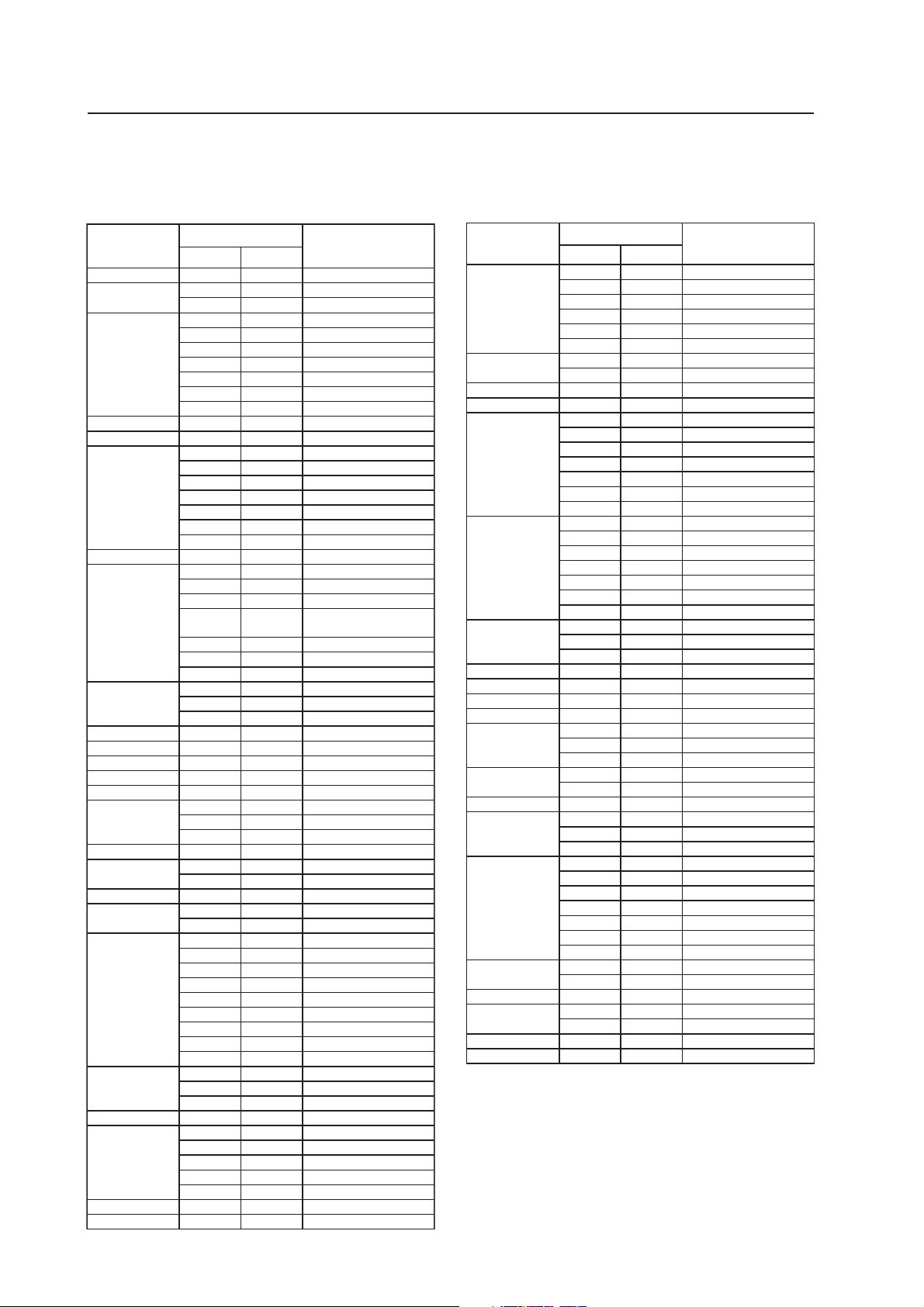
INPUT Response Signals
INPUT 1
7 PC signals supported
Resolution
(Dot x Line)
640x400 70.1 Hz 31.5 kHz NEC PC-9800
720x400 70.1 Hz 31.5 kHz NEC PC-9800
640x480 59.9 Hz 31.5 kHz
848x480 60 Hz 31.0 kH z
852x480 60 Hz 31.7 kH z
800x600 56.3 Hz 35.2 kHz
832x624 74.6 Hz 49.7 kHz Apple Macintosh 16”
1024x768 60 Hz 48.4 kH z
1280x768 56.2 Hz 45.1 kH z
1360x765
1360x768
1376x768 59.9 Hz 48.3 kHz I/O DATA
1280x800 59.8 Hz 49.7 kHz CVT
1280x854 60 Hz 53.1 kHz
1152x864 60 Hz 53.7 kH z
1152x870 75.1 Hz 68.7 kHz Apple Macintosh 21”
1152x900 66 Hz 61.8 kHz Sun Microsystems LO
1440x900 59.9 Hz 55.9 kHz Apple Macintosh 17”
1280x960 60 Hz 60.0 kH z
1280x1024 60 Hz 63.9 kHz Work station (SGI)
1400x1050 60 Hz 65.3 kH z
1680x1050 60 Hz 65.3 kH z
1600x1200 60 Hz 75.0 kH z
1920x1200 59.9 Hz 74.6 kHz CVT
1920x1200RB 60 Hz 74.0 kHz CVT
Refresh rate
Vertical
85.1 Hz 37.9 kHz
66.7 Hz 35.0 kHz Apple Macintosh 13”
72.8 Hz 37.9 kHz
75 Hz 37.5 kHz
85 Hz 43.3 kHz
100.4 Hz 51.1 kHz I/O DATA
120.4 Hz 61.3 kHz I/O DATA
60.3 Hz 37.9 kHz
72.2 Hz 48.1 kHz
75 Hz 46.9 kHz
85.1 Hz 53.7 kHz
99.8 Hz 63.0 kHz I/O DATA
120 Hz 75.7 kHz I/O DATA
60 Hz 49.7 kHz Work station (SGI)
70.1 Hz 56.5 kHz
75 Hz
(74.9 Hz )
85 Hz 68.7 kHz
100.6 Hz 80.5 kHz I/O DATA
119.4 Hz 95.5 kHz
59.8 Hz 48 kHz
69.8 Hz 56 kHz
60 Hz
60 Hz
72 Hz 64.9 kHz
75 Hz 67.5 kHz
76 Hz 71.7 kHz Sun Microsystems HI
85 Hz 85.9 kHz
60 Hz 64.0 kHz
60 Hz 64.6 kHz
71.2 Hz 75.1 kHz
72 Hz 78.1 kHz Work station (HP)
75 Hz 80.0 kHz
76.1 Hz 81.1 kHz Work station (SUN)
85 Hz 91.1 kHz
100.1 Hz 108.5 kHz I/O DATA
74.9 Hz 82.3 kHz
85 Hz 93.9 kHz
65 Hz 81.3 kHz
70 Hz 87.5 kHz
75 Hz 93.8 kHz
85 Hz 106.3 kH z
Horizontal
60.0 kHz
(60.2 kHz)
47.7 kHz
47.7 kHz
Remark
( ) indicates Apple
Macintosh 19
I/O DATA
PC
Work station (EWS4800)
Work station (EWS4800)
INPUT 2
7 PC signals supported
Resolution
(Dot x Line)
640x480 59.9 Hz 31.5 kHz
720x400 70.1 Hz 31.5 kHz NEC PC-9800
848x480 60 Hz 31.0 kH z
852x480 60 Hz 31.7 kH z
800x600 56.3 Hz 35.2 kHz
1024x768 60 Hz 48.4 kH z
1280x768 56.2 Hz 45.1 kH z
1280x800 59.8 Hz 49.7 kH z
1280x854 60 Hz 53.1 kH z
1360x768 60 Hz 47.7 kHz I/O DATA
1376x768 59.9 Hz 48.3 kHz I/O DATA
1152x864 60 Hz 53.7 kH z
1152x900 66 Hz 61.8 kHz Sun Microsystems LO
1440x900 59.9 Hz 55.9 kHz Apple Macintosh17“
1280x960 60 Hz 60.0 kH z
1280x1024 60 Hz 64.0 kH z
1400x1050 60 Hz 65.3 kH z
1680x1050 60 Hz 65.3 kH z
1920x1080 50 Hz 56.2 kH z
1600x1200 60 Hz 75.0 kH z
1920x1200RB 60 Hz 74.0 kHz CVT
Refresh rate
Vertical
72.8 Hz 37.9 kHz
75 Hz 37.5 kHz
85 Hz 43.3 kHz
100.4 Hz 51.1 kHz
120.4 Hz 61.3 kHz
85.1 Hz 37.9 kHz
60.3 Hz 37.9 kHz
72.2 Hz 48.1 kHz
75 Hz 46.9 kHz
85.1 Hz 53.7 kHz
99.8 Hz 63.0 kHz
120 Hz 75.7 kHz
60 Hz 49.7 kHz Work station (SGI)
70.1 Hz 56.5 kHz
75 Hz 60.0 kHz
85 Hz 68.7 kHz
100.6 Hz 80.5 kHz
119.4 Hz 95.5 kHz
59.8 Hz 48 kHz
69.8 Hz 56 kHz
72 Hz 64.9 kHz
75 Hz 67.5 kHz
76 Hz 71.7 kHz Sun Microsystems HI
85 Hz 85.9 kHz
60 Hz 63.9 kHz Work station (SGI)
60 Hz 64.6 kHz
71.2 Hz 75.1 kHz
72 Hz 78.1 kHz Work station (HP)
75 Hz 80.0 kHz
76.1 Hz 81.1 kHz Work station (SUN)
85 Hz 91.1 kHz
74.9 Hz 82.3 kHz
60 Hz 67.5 kHz
Horizontal
Remarks
Work station (EWS4800
Work station (EWS4800)
)
8
Page 9
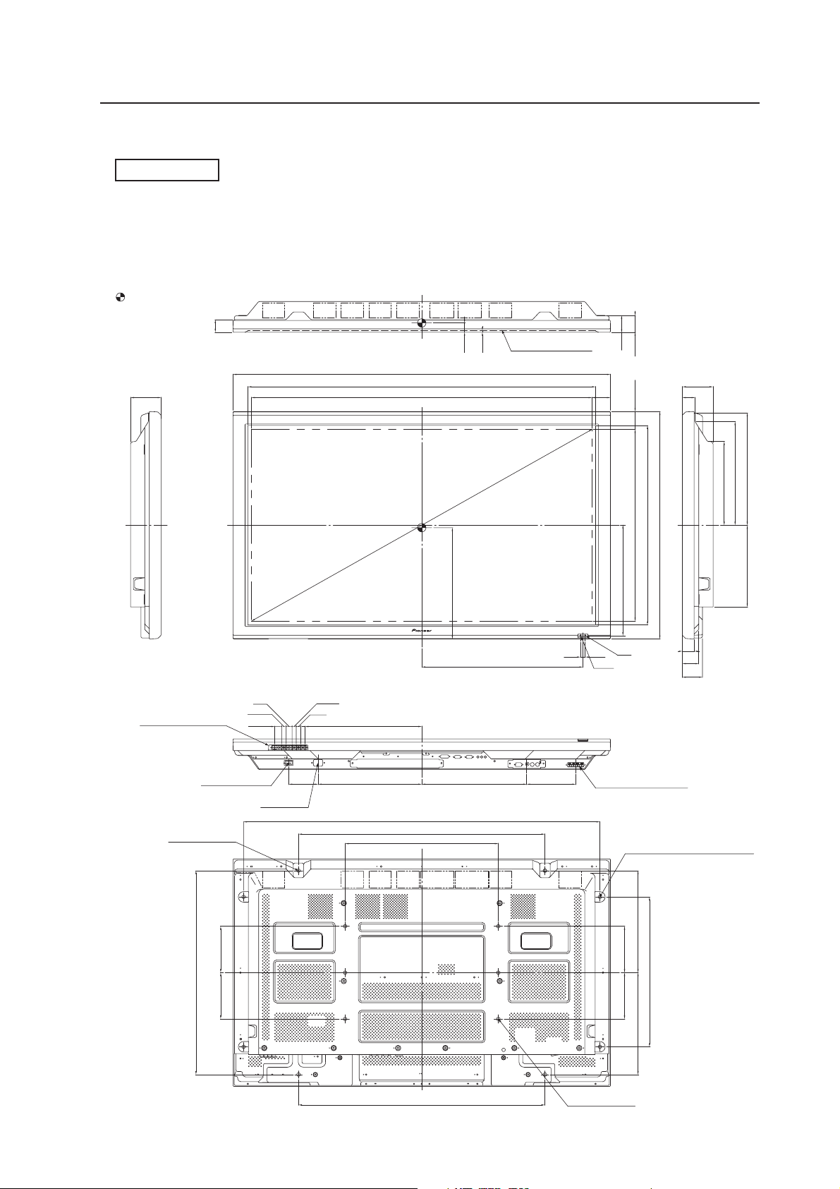
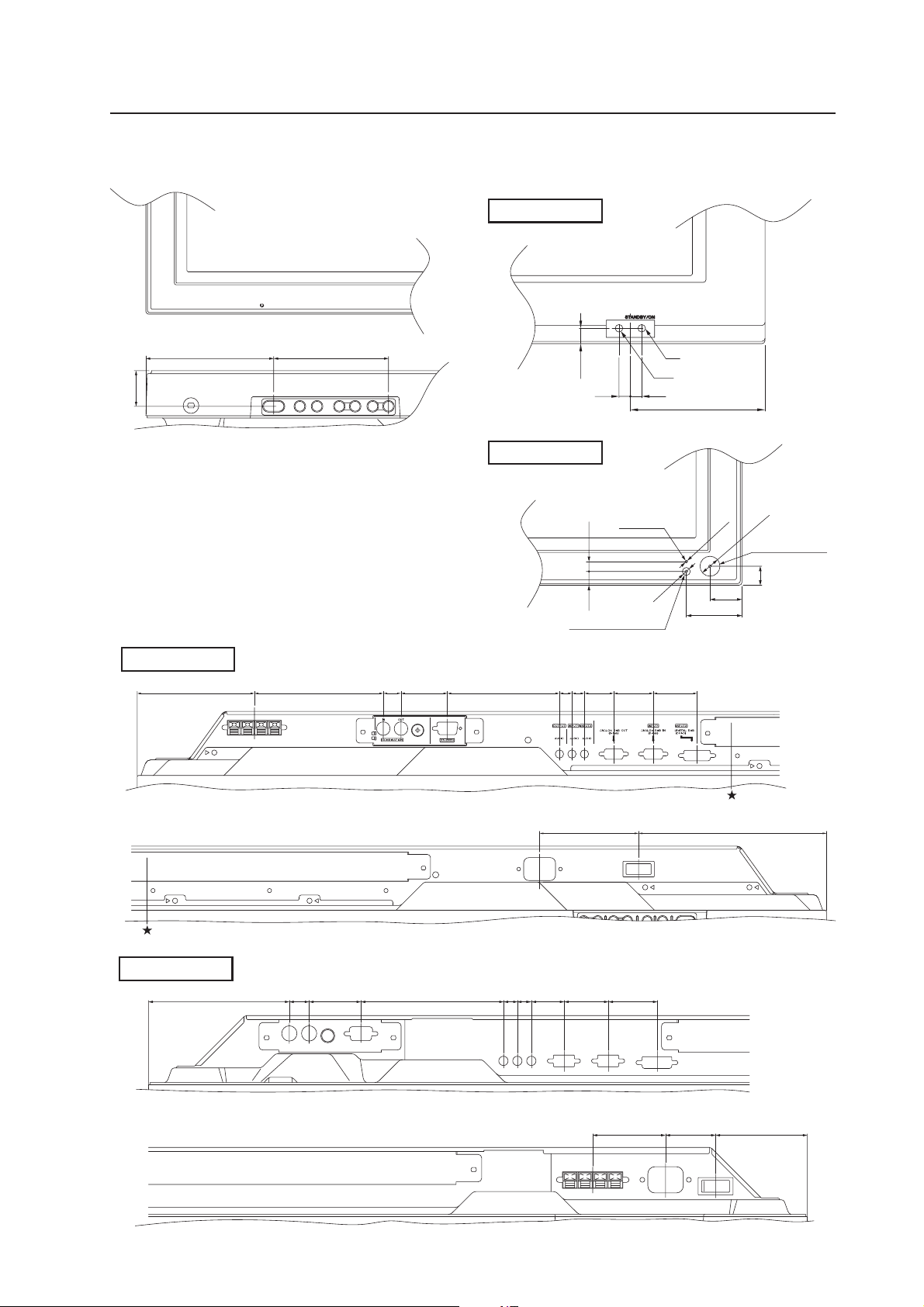
2.2 External Dimensions
PDP-507CMX
WEIGHT: 35.5 kg (78.3 lbs) (without stand)
MATERIAL: Front: Resin; Rear cover: Metal plate, Front protector panel: Glass
TREATMENT: Front: Paint; Rear cover: Paint (All paints are Pioneer original colors)
For packaging information, refer to “3.4.2 Unpacking” (pg. 30).
(Unit: mm)
: center of gravity
41
5.5
FILTER SURFACE
TOP VIEW
1222
1126
99
1103.6(SCREEN AREA)
30
External Dimensions
53
54.5
59
57.55
99
41
363.7
335.5
271
LEFT SIDE VIEW
CONTROL BUTTONS
POWER BUTTON
4-M8.DEPTH14
19
14.7
22.3
AC INLET
736
646
1266.3
360
522
13.5
15
13.5
95
378
335.7 339.9 158.6
7.5
620.9(SCREEN AREA)
357.85
IR
7.5
LED
RIGHT SIDE VIEW
SPEAKER TERMINAL
264.6
38
53
65
BOTTOM VIEW
1154
798
496
FOR SPEAKER(M8.DEPTH12)
330330
660
150150
798
REAR VIEW
150150
485
6-M8.DEPTH18
9
Page 10
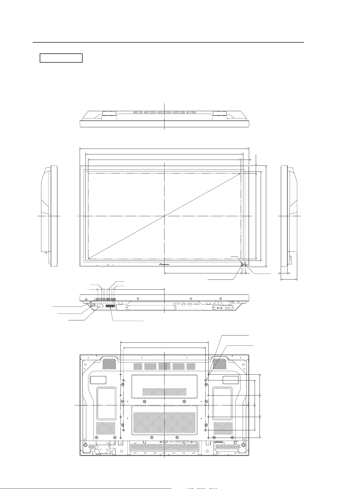
External Dimensions
PDP-427CMX
WEIGHT: 30.5 kg (67.3 lbs) (without stand)
MATERIAL: Front: Resin; Rear cover: Metal plate, Front protector panel: Glass
TREATMENT: Front: Paint; Rear cover: Paint (All paints are Pioneer original colors)
For packaging information, refer to “3.4.2 Unpacking” (pg. 30).
(Unit: mm)
TOP VIEW
1022
952
921.6(SCREEN AREA) 50.2
LEFT SIDE VIEW
CONTROL BUTTONS
POWER BUTTON
AC INLET
22.3
14.7
15
19
SPEAKER TERMINAL
13.5
13.5
304
1055.89
BOTTOM VIEW
530
496
610
538
515.33(SCREEN AREA) 47.34
LED
468.6 18 40.4
Ambient light sensor
Light sensor
RIGHT SIDE VIEW
for mount unit
8-M4 DEPTH 16
for mount unit
6-M8 DEPTH 18
98
10
126130126
150150
REAR VIEW
Page 11
External Dimensions
<Main Unit Operation Panel> <Light Sensor for the remote/ambient light
sensor/indicator>
PDP-507CMX
109 98
30.3
<Connection panel>
PDP-507CMX
(112.5) 123.6 17 44.5 107.5 12 12 28 38 42
10.15
PDP-427CMX
Ambient light sensor
10.5 7.5
Indicator
IR
LED
7.57.5
89
ø2
ø15.2
Light sensor for
the remote
14.5
ø6
24.4
42.4
PDP-427CMX
(121) 17 44.5 122.6 12 12 28 38 42
(180.3)95
62.5 43 (78.8)
11
Page 12
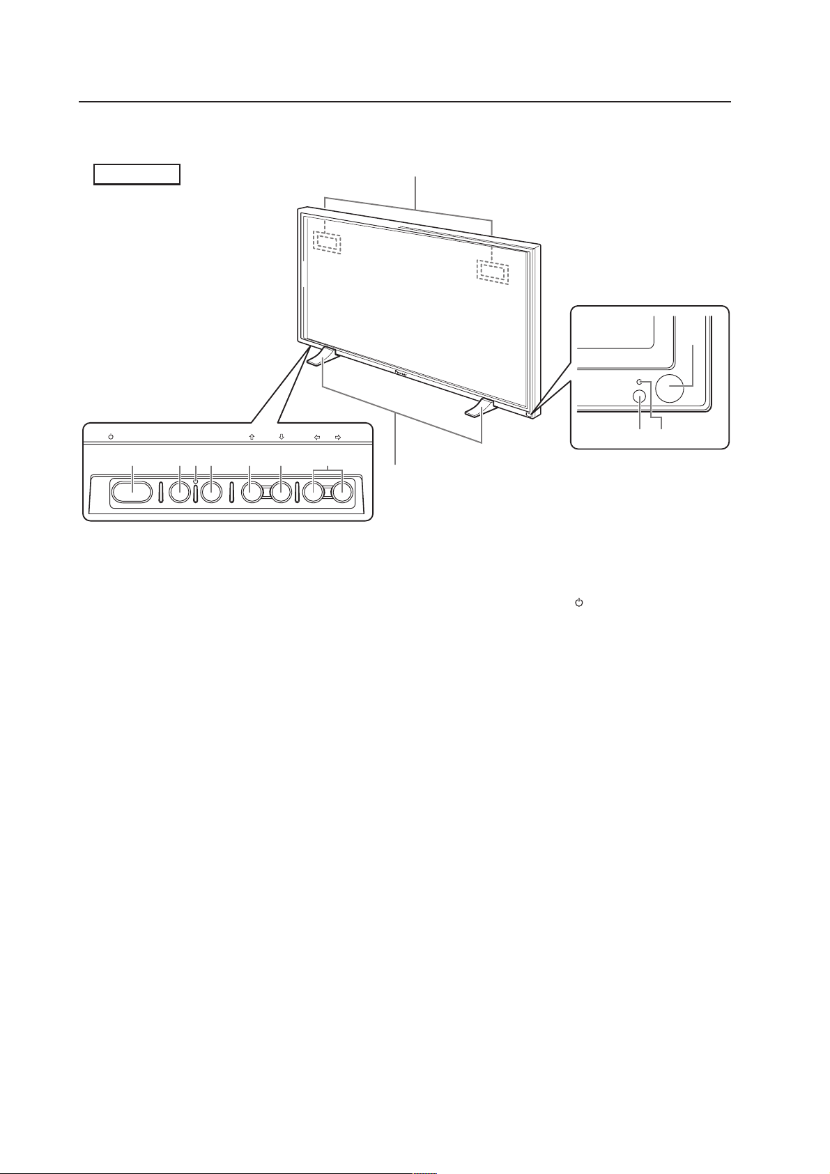
Controls and Connectors
2.3 Controls and Connectors
Main unit
Main unit
Operation panel on the
main unit
STANDBY/ON MENU
DISPLAY
/ SET
7 8= 9 06
* Illustration depicts PDP-427CMX model.
– VOL +INPUT SCREEN SIZE
1
5
STANDBY
2
ON
3
4
Main unit
1 Display stand (PDP-427CMX only)
2 Remote control sensor
Point the remote control toward the remote sensor
to operate the unit.
3 Ambient light sensor
This sensor measures the level of light inside the
viewing room; it is enabled when the [ENERGY
SAVE] option is set to [AUTO].
4 STANDBY/ON indicator
When the unit is operating:
The indicator lights green.
When flashing, the light indicates an error.
The indicator flashes green once per second when
the [POWER MGT.] function is operating.
When the unit is in Standby, the indicator lights red.
When flashing, the light indicates an error.
5 Handles
Operation panel on the main unit
6 STANDBY/ON button ( )
Press to put the display in Standby or into operation.
7 MENU button
Press to open and close the on-screen menu.
8 DISPLAY/SET button
Use to confirm on-screen menu selections and to
change settings.
When not in use by on-screen menus, press to
display the current set status.
9 INPUT (’) button
Except when menu screen is displayed, this button
can change the input.
0 SCREEN SIZE (‘) button
Except when menu screen is displayed, this button
can change the screen size.
- VOL +/– (}/]) buttons
When not in use for by on-screen menus, these
buttons can adjust the sound volume.
= Functional lock button (concealed button)
This button is used to switch between permitted
and blocked operation of the control panel and the
remote control. It can also set the input function
memory.
12
Page 13
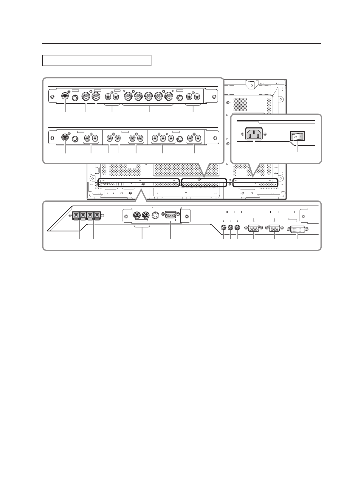
Connection Panel (PDP-507CMX)
When installing PDA-5003
S-VIDEO
INPUT3
INPUT4
VIDEO
AUDIO
INPUT 3/4 ANALOG RGB AUDIO
Controls and Connectors
INPUT5
~
OUT R L
IN
!@
#
BR VD RL
G(ON SYNC)
$
When installing PDA-5004
IN OUT
COMBINATION
COMPONENT
VIDEO
S-VIDEO
INPUT3 INPUT4 INPUT5
^
AUDIO AUDIO AUDIO
VIDEO
RL RL RLY Pb/Cb Pr/CrIN OUT
&)_
*(
21 8 9 03567
Plasma Display Section
1 SPEAKER (R) terminal
For connection of an external right speaker.
Connect a speaker that has an impedance of 6 Ω to
16 Ω.
2 SPEAKER (L) terminal
For connection of an external left speaker. Connect
a speaker that has an impedance of 6 Ω to 16 Ω.
3 COMBINATION IN/OUT
Never connect any component to these
connectors without first consulting your Pioneer
installation technician.
These connectors are used for Plasma Display
setup adjustments.
4 RS-232C
Never connect any component to this connector
without first consulting your Pioneer installation
technician.
This connector is used for Plasma Display setup
adjustments.
5 AUDIO (OUTPUT) (Stereo mini jack)
Use to output the audio of the selected source
component connected to this unit to an AV amplifier
or similar component.
Note: No sound is produced from the AUDIO (OUTPUT)
jack when the MAIN POWER switch is set to OFF or when
set to Standby.
HD (H/V SYNC)
RS-232C
4
%
INPUT2
DIGITAL RGB
(DVI-D)
=-
+
INPUT1
OUTPUT INPUT2
AUDIO
AUDIO AUDIO
ANALOG RGB OUT
(D-Sub)
INPUT1
ANALOG RGB IN
(D-Sub)
6 AUDIO (INPUT1) (Stereo mini jack)
Use to obtain sound when INPUT1 is selected.
Connect the audio output jack of components
connected to INPUT1 to this unit.
7 AUDIO (INPUT2) (Stereo mini jack)
Use to obtain sound when INPUT2 is selected.
Connect the audio output jack of components
connected to INPUT2 to this unit.
8 ANALOG RGB OUT (INPUT1) (mini D-sub 15 pin)
Use the ANALOG RGB OUT (INPUT1) terminal to
output the video signal to an external monitor or
other component.
Note: The video signal is not output from the ANALOG
RGB OUT (INPUT1) terminal when the panel's main power
is OFF or the panel is in Standby.
9 ANALOG RGB IN (INPUT1) (mini D-sub 15 pin)
For connection of a personal computer (PC) or
similar component. Confirm that the connection
made corresponds to the signal output from the
connected component.
0 DIGITAL RGB (INPUT2) (DVI-D jack)
Use to connect a computer.
Note: This unit does not support the display of
copyguard-protected video signals.
- AC IN
Use to connect the supplied power cord to an AC outlet.
= MAIN POWER switch
Use to switch the main power of the unit on and off.
13
Page 14

Controls and Connectors
Video Card <PDA-5003> Section
The video card provides three video input connectors,
one video output connector, and two audio input
connectors. Consult the pages noted in parentheses ( )
for details regarding connections to the various jacks
and connectors.
~ S-VIDEO (INPUT3) (S-video jack)
Use this jack to connect components that have an
S-video output jack such as a video deck, video
camera, laser disc player, or DVD recorder.
! VIDEO IN (INPUT4) (BNC jack)
Use this jack to connect components that have a
composite video output jack such as a video deck,
video camera, laser disc player, or DVD recorder.
@ VIDEO OUT (INPUT4) (BNC jack)
Use this jack to output the video signal to an
external monitor or other component.
Note
The video signal is not output from the VIDEO OUT
(INPUT4) jack when the display is OFF or in the Standby
mode.
# AUDIO R/L (INPUT3/4) (RCA Pin jacks)
Use this jack to obtain sound when INPUT3 or
INPUT4 is selected. Connect these jacks to the
component’s audio outputs that are connected to
the video card’s INPUT3 or INPUT4.
$ ANALOG RGB (INPUT5) (BNC jacks)
Use this jack to connect components equipped with
RGB outputs jacks such as personal computers,
external RGB decoders, or components equipped
with component output jacks such as DVD
recorders. Verify that the connection corresponds to
the signal output from the connected component.
% AUDIO R/L (INPUT5) (RCA Pin jacks)
Use this jack to obtain sound when INPUT5 is
selected.
Connect these jacks to the component’s audio
outputs that are connected to the video card’s
INPUT5.
Video Card <PDA-5004> Section
The video card provides three video input connectors,
one video output connector, and three audio input
connectors. Consult the pages noted in parentheses ( )
for details regarding connections to the various jacks
and connectors.
^ S-VIDEO (INPUT3) (S-video jack)
Use this jack to connect components that have an
S-video output jack such as a video deck, video
camera, laser disc player, or DVD recorder.
& AUDIO R/L (INPUT3) (RCA Pin jacks)
Use this jack to obtain sound when INPUT3 is
selected.
Connect these jacks to the component’s audio
outputs that are connected to the video card’s
INPUT3.
* VIDEO IN (INPUT4) (RCA Pin jack)
Use this jack to connect components that have a
composite video output jack such as a video deck,
video camera, laser disc player, or DVD recorder.
( VIDEO OUT (INPUT4) (RCA Pin jack)
Use this jack to output the video signal to an
external monitor or other component.
Note
The video signal is not output from the VIDEO OUT
(INPUT4) jack when the display is OFF or in Standby.
) AUDIO R/L (INPUT4) (RCA Pin jacks)
Use this jack to obtain sound when INPUT4 is
selected.
Connect these jacks to the component’s audio
outputs that are connected to the video card’s
INPUT4.
_ COMPONENT VIDEO (INPUT5) (RCA Pin jacks)
Use this jack to connect devices that have
component video output jacks such as DVD
recorders.
+ AUDIO R/L (INPUT5) (RCA Pin jacks)
Use this jack to obtain sound when INPUT5 is
selected.
Connect these jacks to the device’s audio outputs
that are connected to the video card’s INPUT5.
14
Page 15
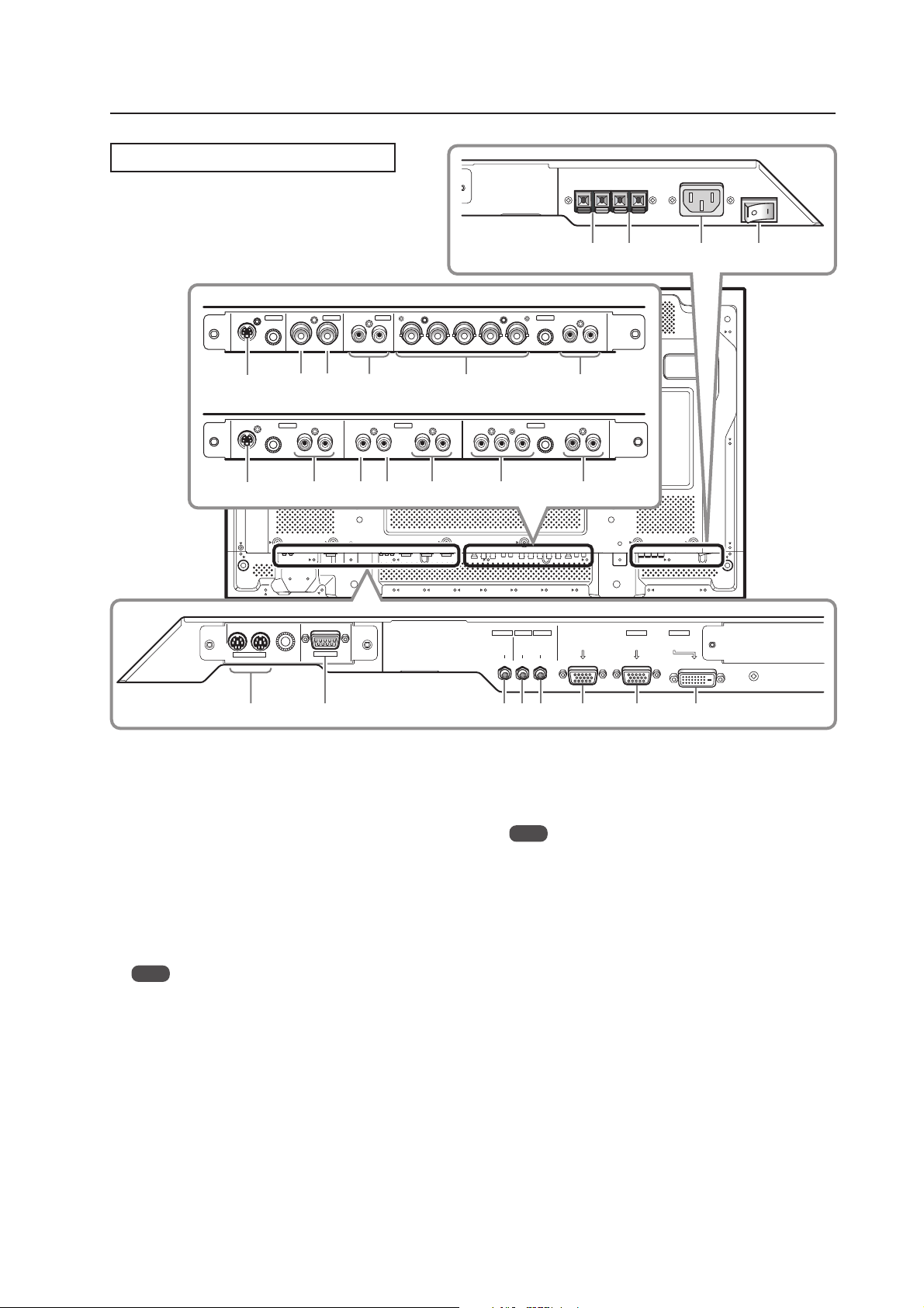
Connection Panel (PDP-427CMX)
When installing PDA-5003
S-VIDEO
INPUT3
INPUT4
VIDEO
INPUT 3/4 ANALOG RGB AUDIO
AUDIO
Controls and Connectors
=-09
INPUT5
OUT R L
IN
~
! @
#
When installing PDA-5004
INPUT3 INPUT4 INPUT5
S-VIDEO
^
IN OUT
COMBINATION
13
AUDIO AUDIO AUDIO
VIDEO
RL RL RLY Pb/Cb Pr/CrIN OUT
* (
& ) _
RS-232C
2
Plasma Display Section
1 COMBINATION IN/OUT
These connectors are used for Plasma Display
setup adjustments.
2 RS-232C
This connector is used for Plasma Display setup
adjustments.
3 AUDIO (OUTPUT) (Stereo mini jack)
Use this port to output the audio of the selected
source component that is connected to the Plasma
Display, to an AV amplifier or similar component.
Note
No sound is produced from the AUDIO (OUTPUT) jack
when the display is OFF or in the Standby mode.
4 AUDIO (INPUT1) (Stereo mini jack)
Use this port to obtain sound when INPUT1 is
selected. Connect this jack to the audio output
connector on the device that is connected to the
plasma panel’s INPUT1.
5 AUDIO (INPUT2) (Stereo mini jack)
Use this port to obtain sound when INPUT2 is
selected. Connect this jack to the audio output
connector on the device connected to the Plasma
Display’s INPUT2.
BR VD RL
G(ON SYNC)
HD (H/V SYNC)
$
COMPONENT
VIDEO
INPUT1
OUTPUT INPUT2
AUDIO
AUDIO AUDIO
6 ANALOG RGB OUT (INPUT1) (mini D-sub 15 pin)
Use this connector to output the video signal to an
external monitor or other component.
Note
The video signal is not output from the ANALOG RGB OUT
(INPUT1) connector when the main power of this display is
OFF or in Standby mode.
7 ANALOG RGB IN (INPUT1) (mini D-sub 15 pin)
Use this input to connect components equipped
with RGB outputs jacks such as personal
computers. Verify that the connection corresponds
the signal output format from the connected
component.
8 DIGITAL RGB (INPUT2) (DVI-D jack)
Use this input to connect to a computer.
Connect to an AV component (HDCP supported)
equipped with DVI output connector.
9 SPEAKER (R) terminal
Use this port to connect an external right speaker.
Connect a speaker whose impedance is 6 Ω to 16 Ω.
0 SPEAKER (L) terminal
Use this port to connect an external left speaker.
Connect a speaker whose impedance is 6 Ω to 16 Ω.
%
+
ANALOG RGB OUT
(D-Sub)
6 7 845
INPUT1
ANALOG RGB IN
(D-Sub)
INPUT2
DIGITAL RGB
(DVI-D)
15
Page 16

Controls and Connectors
- AC IN
A power cable is furnished with the Plasma Display.
Connect one end of the power cable to this
connector and the other end to a standard AC
power source.
= MAIN POWER switch
Use this switch to toggle the panel’s main power
ON and OFF.
Video Card <PDA-5003> Section
The video card is provided with 3 video input
connectors, 1 video output connector and 2 audio input
connectors. Consult the pages noted in parentheses ( )
for details regarding connections to the various jacks
and connectors.
~ S-VIDEO (INPUT3) (S-video jack)
Use this jack to connect components that have an
S-video output jack such as a video deck, video
camera, laser disc player, or DVD recorder.
! VIDEO IN (INPUT4) (BNC jack)
Use this jack to connect components that have a
composite video output jack such as a video deck,
video camera, laser disc player, or DVD recorder.
@ VIDEO OUT (INPUT4) (BNC jack)
Use this jack to output the video signal to an
external monitor or other component.
Note
The video signal is not output from the VIDEO OUT
(INPUT4) jack when the display is OFF or in the Standby
mode.
# AUDIO R/L (INPUT3/4) (RCA Pin jacks)
Use this jack to obtain sound when INPUT3 or
INPUT4 is selected. Connect these jacks to the
component’s audio outputs that are connected to
the video card’s INPUT3 or INPUT4.
$ ANALOG RGB (INPUT5) (BNC jacks)
Use this jack to connect components equipped with
RGB outputs jacks such as personal computers,
external RGB decoders, or components equipped
with component output jacks such as DVD
recorders. Verify that the connection corresponds to
the signal output format from the connected
component.
% AUDIO R/L (INPUT5) (RCA Pin jacks)
Use this jack to obtain sound when INPUT5 is
selected.
Connect these jacks to the component’s audio
outputs that are connected to the video card’s
INPUT5.
Video Card <PDA-5004> Section
The video card provides 3 video input connectors, 1
video output connector and 3 audio input connectors.
Consult the pages noted in parentheses ( ) for details
regarding connections to the various jacks and
connectors.
^ S-VIDEO (INPUT3) (S-video jack)
Use this jack to connect components that have an
S-video output jack such as a video deck, video
camera, laser disc player, or DVD recorder.
& AUDIO R/L (INPUT3) (RCA Pin jacks)
Use this jack to obtain sound when INPUT3 is
selected.
Connect these jacks to the component’s audio
outputs that are connected to the video card’s
INPUT3.
* VIDEO IN (INPUT4) (RCA Pin jack)
Use this jack to connect components that have a
composite video output jack such as a video deck,
video camera, laser disc player, or DVD recorder.
( VIDEO OUT (INPUT4) (RCA Pin jack)
Use this jack to output the video signal to an
external monitor or other component.
Note
The video signal is not output from the VIDEO OUT
(INPUT4) jack when the display is OFF or in the Standby
mode.
) AUDIO R/L (INPUT4) (RCA Pin jacks)
Use this jack to obtain sound when INPUT4 is
selected.
Connect these jacks to the component’s audio
outputs that are connected to the video card’s
INPUT4.
_ COMPONENT VIDEO (INPUT5) (RCA Pin jacks)
Use this jack to connect devices that have
component video output jacks such as DVD
recorders.
+ AUDIO R/L (INPUT5) (RCA Pin jacks)
Use this jack to obtain sound when INPUT5 is
selected.
Connect these jacks to the device’s audio outputs
that are connected to the video card’s INPUT5.
16
Page 17
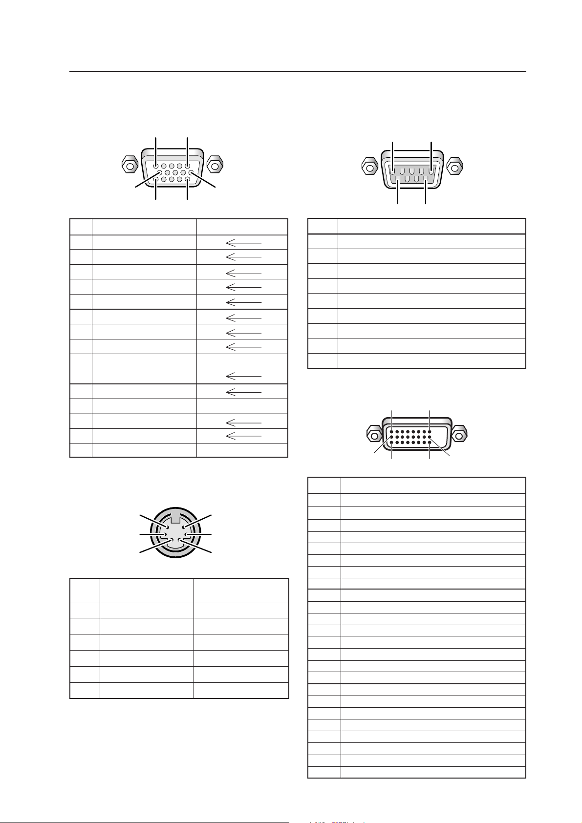
2.4 Pin layout
INPUT1 (Mini D-sub, 15-pin connector; female)
pin layout
5
1
Pin layout
RS-232C terminal (D-sub 9-pin connector; male)
pin layout (DCE format)
1
5
6
Pin No.
10
1115
Input Output
1R
2G
3B
4 NC (not connected)
5 GND
6 GND
7 GND
8 GND
9 DDC +5V NC (not connected)
10 GND
11 NC (not connected)
12 DDC SDA NC (not connected)
13 HD or H/V SYNC
14 VD
15 DDC SCL NC (not connected)
96
Pin No.
Signal
1 NC (not connected)
2 TxD (Transmit Data)
3 RxD (Receive Data)
4 NC (not connected)
5 GND
6 NC (not connected)
7 NC (not connected)
8 RTS (Request To Send)
9 NC (not connected)
INPUT2 (DVI-D 24 pin connector; female)
pin layout
12
9
16
2417
Combination IN/OUT terminal pin layout
6
4
2
Pin No.
Combination Combination
IN OUT
1 GND GND
2 NC (not connected) NC (not connected)
3 TxD (output) RxD (input)
4 NC (not connected) NC (not connected)
5 RxD (input) TxD (output)
6 NC (not connected) NC (not connected)
5
3
1
Pin No.
1
2
3
4
5
6
7
8
9
10
11
12
13
14
15
16
17
18
19
20
21
22
23
24
Signal Assignment
T.M.D.S. Data2–
T.M.D.S. Data2+
T.M.D.S. Data2/4 Shield
NC (No connection)
NC (No connection)
DDC Clock
DDC Data
NC (No connection)
T.M.D.S. Data1–
T.M.D.S. Data1+
T.M.D.S. Data1/3 Shield
NC (No connection)
NC (No connection)
+5V Power
GND
Hot Plug Detect
T.M.D.S. Data0 –
T.M.D.S. Data0+
T.M.D.S. Data0/5 Shield
NC (No connection)
NC (No connection)
T.M.D.S. Clock Shield
T.M.D.S. Clock+
T.M.D.S. Clock–
17
Page 18
Remote Control Unit
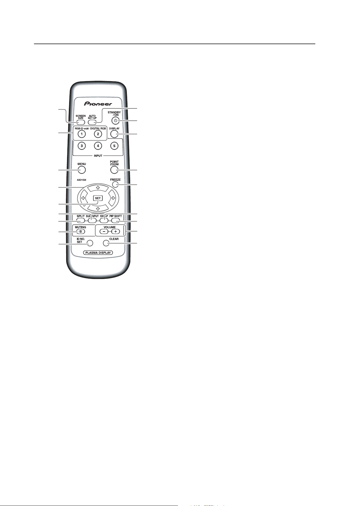
2.5 Remote Control Unit
1
2
3
4
0
-
=
~
!
1 SCREEN SIZE button
Press to select the screen size.
2 INPUT buttons
Press to select the input.
3 MENU button
Press to reveal and hide the on-screen menu.
4 ADJUST (5/∞/3/2) buttons
Press to navigate menu screens and adjust various
settings on the unit.
5 SET button
Press to adjust or enter various settings on the unit.
6 SUB INPUT button
Press to change subscreen inputs during multiscreen display.
5
7
8
9
@6
#
$
%
7 SPLIT button
Press to switch to multi-screen display.
8 MUTING button
Press to mute the volume.
9 ID NO. SET button
Press to select which position the panel holds in a
video wall.
0 AUTO SET UP button
Press to automatically set the [POSITION], [CLOCK].
and [PHASE] to optimum values when using a
computer signal.
- STANDBY/ON button
Press to activate the display or place in Standby.
= DISPLAY button
Press to view the unit’s current input and setup
mode.
~ POINT ZOOM button
Press to select and enlarge a portion of the screen.
! FREEZE button
Press to display a still image in the subscreen when
the memo screen function is enabled.
18
@ SWAP button
Press to switch between the main screen and the
subscreen during multi-screen display.
# PIP SHIFT button
Press to move the position of the subscreen when
viewing in PinP mode with multi-screen dsplay.
$ VOLUME (+/–) buttons
Press to adjust the volume.
% CLEAR button
Press to clear for program timer and ID assignment.
Page 19
Remote Control Unit Holder
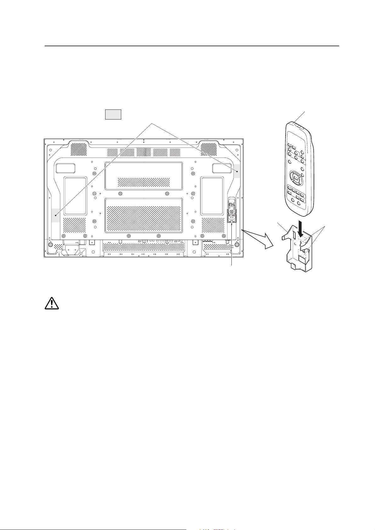
2.6 Remote Control Unit Holder (PDP-427CMX only)
Peel the sticker covers from the lower and upper mounting tapes on the rear of the remote control holder. Attach it to
the back of the main unit or on some other fixed surface so that it will be available for storing the remote control with
the panel.
Area of remote control
unit holder attachment
Remote control
unit holder
Example of remote control
unit holder attachment
Remote control unit
Upper and
lower tape
Do not block ventilation holes with the remote control holder.
Caution
19
Page 20
Installation Site Requirements
[507CMX : 427CMX]
3.1 Installation Site Requirements
If the site requires modifications or special preparations before installing the Plasma Display or its mounting hardware,
obtain permission in advance from the building owner or building authorities. To ensure safety, it is also important to
determine the strength of the installation site with the help of an authorized building contractor.
Safety Precautions
1) Structure of the installation site
Thoroughly study the structure of the installation site before determining the most suitable installation method.
Buildings vary in structure and materials, thus the best mounting choice differs at each location. When drilling into
walls, check for internal electrical wiring and hidden pipes.
2) Weight capacity of the installation site
Select a location sufficient to support the total weight of the display and mounting hardware.
3) Flat, level surfaces
Select a flat, level surface so that the mounting hardware is parallel to the proposed mounting surface.
Install the unit so that the load is evenly distributed along the ceiling or floor, as well as on mounting hardware such as
from hang bolts.
4) Sufficient work space
Select a location with sufficient space for installation preperations. The panel mounting should be conducted by two or
more people.
5) Nearby equipment
If air conditioning ducts, lamps, etc. are located near the installation site, dust, temperatures fluctuations, humidity, and
condensation may cause problems. Please take steps to avoid this possibility.
6) Safe locations
Do not install the unit where it may be easily touched or leaned against. Avoid locations subject to high vibration or
severe impacts.
7) Lighting conditions
• Check existing lighting and sunlight angles when considering an installation layout. Bright lighting can reduce the
visibility and quality of a displayed image.
• In very bright surroundings, adjusting screen intensity may not result in perceptibly brighter images. Extreme intensity
settings can reduce a system’s service life.
8) Other installation conditions
The panel is designed for indoor use and is not suited for open-air use. Installation in locations that are even partially
exposed to the elements may lead to malfunctions or breakdown. If there is a danger of being subjected to the conditions
listed below, it is necessary to limit the exposure as much as possible.
• Water or other liquids and dust
• Temperature and humidity changes
• Salt-bearing wind
• Direct sunlight (avoid sites exposed to direct sunlight upon the display as this can degrade image quality)
20
Page 21
[507CMX : 427CMX]
9) Temperature and humidity conditions
• The installation site should meet the following conditions:
• Operating temperatures: 0 °C to 40 °C (largely depending on installation conditions)
• Operating humidity: 20 % to 80 %
• Storage temperature: –20 °C to 60 °C
• Storage humidity: 20 % to 90 %
• Operating atmospheric pressure: 800 hPa to 1100 hPa
• Storage atmospheric pressure: 700 hPa to 1114 hPa
• We discourage installing electronic products such as this unit in locations subject to high humidity. If the unit is to be
installed in a location subject to relatively high humidity, observe the following:
• Failure to install the unit in acceptable ways may result in non-warranty damages.
• Make sure the unit is grounded.
• Do not allow water or other liquids to enter the unit.
10) Prevent condensation
A primary problem during the winter is condensation forming on or in electronic equipment. Rapid temperature fluctuations
can leave water vapor inside the unit or on the screen, degrading performance. If condensation occurs, turn the unit
OFF for an hour or more then increase the room temperature gradually before turning ON the unit.
Consult Pioneer authorized dealers for assistance.
Installation Site Requirements
11) Power requirements
• This unit functions properly when powered at ±10 % of its rated voltage. Characteristics of power lines may effect
the voltage output. If any of the following issues occur, contact an electrician to inspect the power source.
-- Significant voltage drop between the circuit panel and the Plasma Display
-- Significant changes in voltage when switching the display power ON or OFF
• Please allow the following margin for power consumption per unit.
PDP-507CMX: 370 W = 370 VA
PDP-427CMX: 320 W = 320 VA
(NOTE)
When powering up the unit, the in-rush current is approximately 30 A.
• A grounded three-core power cable is used by the Plasma Display in order to maintain its functions.
Connect the power cord by inserting it into a grounded electrical outlet.
When using a different power source, use a conversion plug. Insert it into a grounded electrical outlet and securely
attach the ground wire.
• A leakage current within a value, stipulated by standards in each country, flows from an internal noise filter through
devices installed inside switching power sources such as television sets or air-conditioners. Because these currents
are added together when multiple units are connected, take steps to prevent electric shock caused by ground wires,
etc. When a leakage breaker is installed in a power distribution series, choose the leakage breaker rating that is at
least two times the total leakage current.
When many devices are connected, increase the number of leakage breakers and form branches in the wiring system.
12) Effective remote control distance
The remote control of this display receives at the following angles and distances.
• Front: 8 m
• Left-right 45°: 3 m/Left-right 30°: 7 m
• Upward 30°: 3.5 m/Upward 15°: 5 m
• Downward 30°: 5 m
If other products controlled with infrared remote controls are placed nearby, remote control function may be affected.
In such cases, move other devices further away from the display or contact a Pioneer-authorized dealer for assistance.
Depending on installation conditions, the remote control range may be reduced by infrared radiation emitted by the
screen.
The screen’s infrared intensity varies, depending upon the displayed image.
21
Page 22
Installation Conditions
[507CMX]
3.2 Installation Conditions (PDP-507CMX)
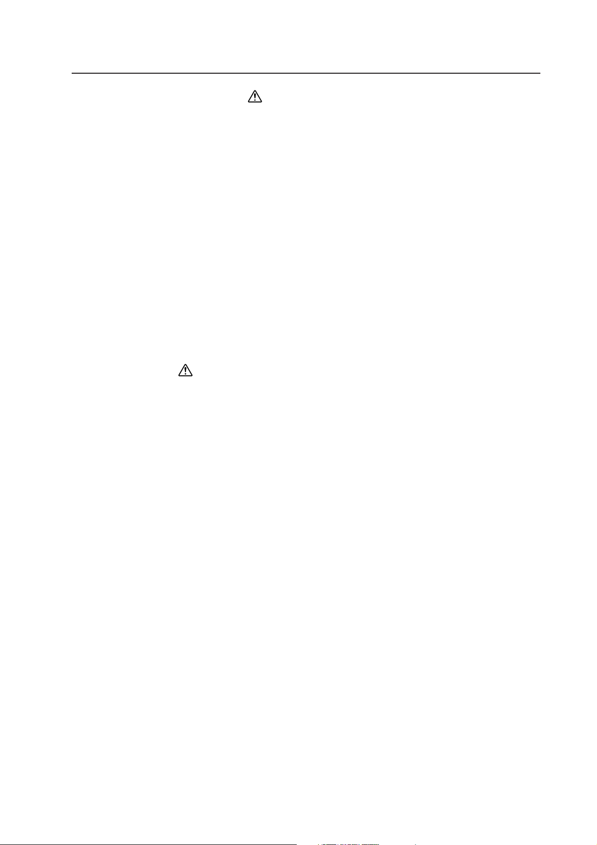
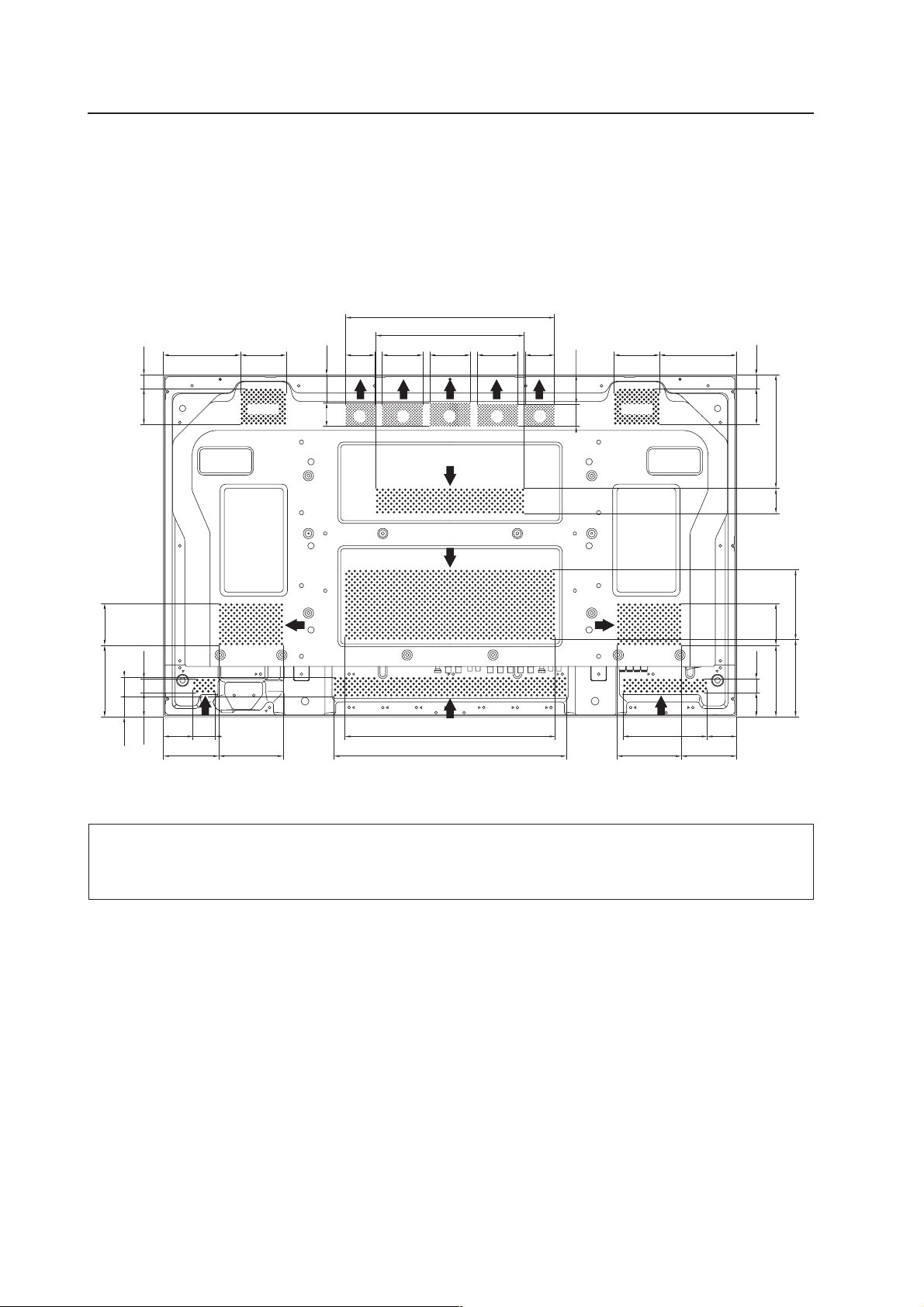
3.2.1 Heat dissipation
This unit has openings for effective ventilation. Vent locations are marked by arrows in the illustration below. The
arrows show the direction of airflow. To allow proper dissipation of heat from the unit, do not cover these openings.
(Unit : mm)
474.5
148.6
114.542.594.5
143.8
143.7
62.5 34.8
48.6 119.8
395.5
157.99.4
246.7
24.593.7
117.9
Fan
68.2
76.7
174.5
194.5133.7
72.5 72.5 72.5
113.7
81
29.8
67.5
171
552.5
107.4 107.4 72.5
52.8
54.5
384.5
34.5
54.54584.5151.3
25.5
117.9
Fan
68.2
76.7 246.7
174.5
24.5
72.5 94.7
AAAAAAAA
119.8
133.7194.5
143.7
93.7
48.6
34.862.5
39.454.8
114.542.594.5
143.8
474.5
148.6
In a standard installation, two fans and part A draw hot air from the unit. All openings not assisted by fans serve as
air inlets. If the unit is hung from or embedded into a wall, special operating temperature limits and other limitations
may apply. Refer to section “3.5 Special Installation (PDP-507CMX)” (pg. 35) for more information.
22
Page 23
[507CMX]
Installation Conditions
3.2.2 Calculating heat quantity
As a courtesy to our customers, we have included the power formula for calculating air conditioning needs.
For power consumption, allow 370 W = 370 VA per unit.
Since most of the power consumed is transformed into heat, power consumption may be regarded as roughly equal to
generated heat.
1 Conversion to calories
[W] × 0.86 = [kcal/h]
Heat generated per display: 370 W × 0.86 = 318 kcal/h
2 Conversion to British Thermal Units
[W] × 3.41 = [BTU/h]
Heat generated per unit: 370 W × 3.41 = 1262 BTU/h
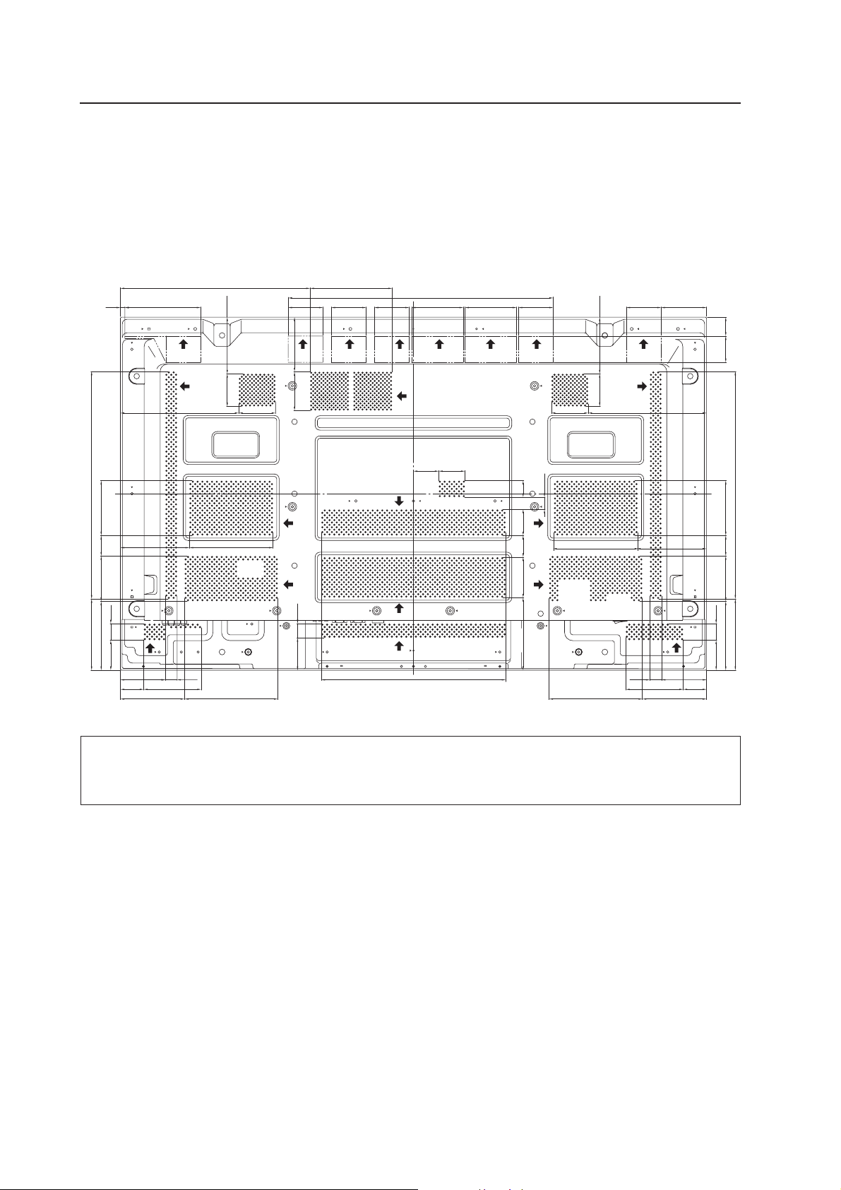
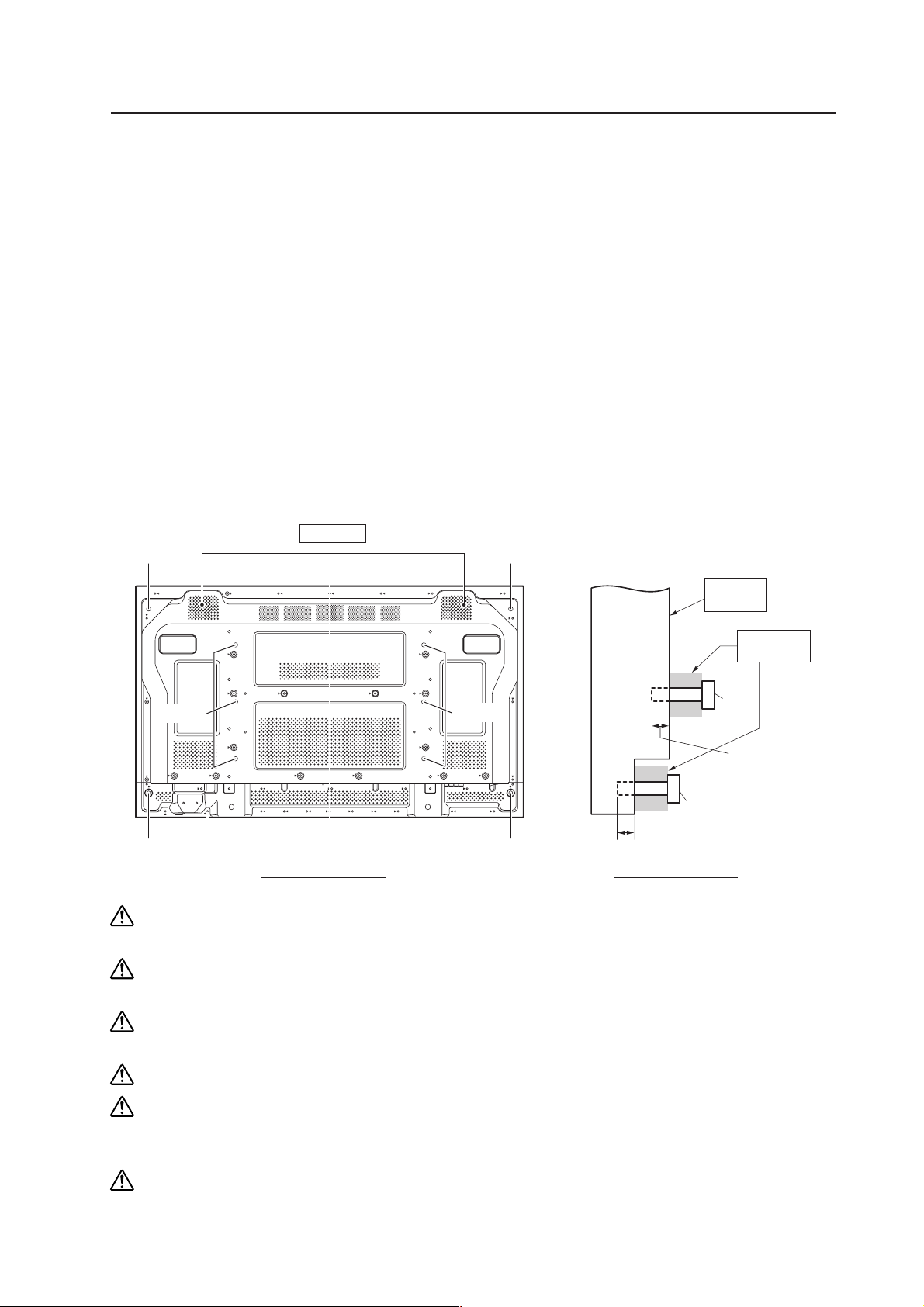
3.2.3 Product mounting holes
We recommend using mounting hardware available from Pioneer. If you use other mounting hardware, mount the
hardware to the unit using the M8-bolt holes on the unit. Tighten the bolts with a torque between 50 kg/cm and 80 kg/
cm. Applying a torque beyond these limits may lead to internal component failure.
Locations of usable mounting holes are shown below.
b hole
b hole
a hole
a holes
a hole
Vent (fan)
Center line
a hole
a holes
a hole
b hole
b hole
a Holes (10 places)
b Holes (4 places)
This unit
Attaching
surface
Installation
bracket etc.
a hole
Bolt
12 mm to
18 mm
b hole
Bolt
12 mm to 14 mm
Rear view diagram Side view diagram
Always use a minimum of 4 mounting holes that are evenly distributed on opposite sides of both the horizontal
and vertical center lines.
Use bolts that can be driven 12 mm to 18 mm into holes “a” and from 12 mm to 14 mm into holes “b” as shown
in the Side View above.
Do not block or cover vents on the rear panel.
Take precautions to prevent the walls from being soiled by the Plasma Display’s exhaust outlets.
This unit incorporates glass components. Install only on flat surfaces.
Always turn every bolt by hand two to three times then check to make sure the bolt is straight.
You may tighten using a tool but do not over-tighten the bolts.
Do not use
loctight
or similar bonding products.
Please use M8 (P=1.25) bolts. DO NOT use any other type of bolt.
23
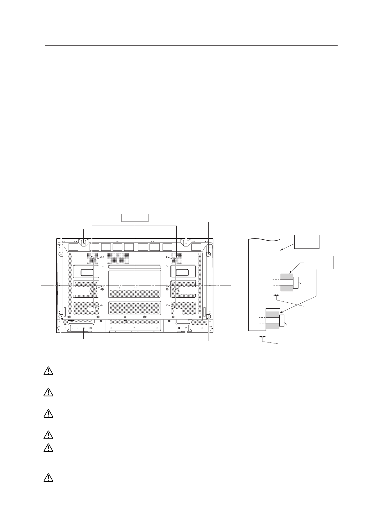
Page 24
Installation Conditions
This unit is designed to be mounted using four bolt holes. For additional safety, we recommend securing it at four or six
points on opposite sides of the horizontal and vertical center lines, as shown in the drawing below.
Poor methods for securing
Suggested methods for securing
Secured at six points
*Attach using M8x6.
[507CMX]
Secured at four points (with mounting hardware attached to the top and bottom)
*Attach using M8x4.
Secured at four points (with mounting hardware attached to the sides)
*Attach using M8x4.
Take proper precautions to prevent pinching the power cord or signal cables.
24
Page 25
[507CMX]
Installation Conditions
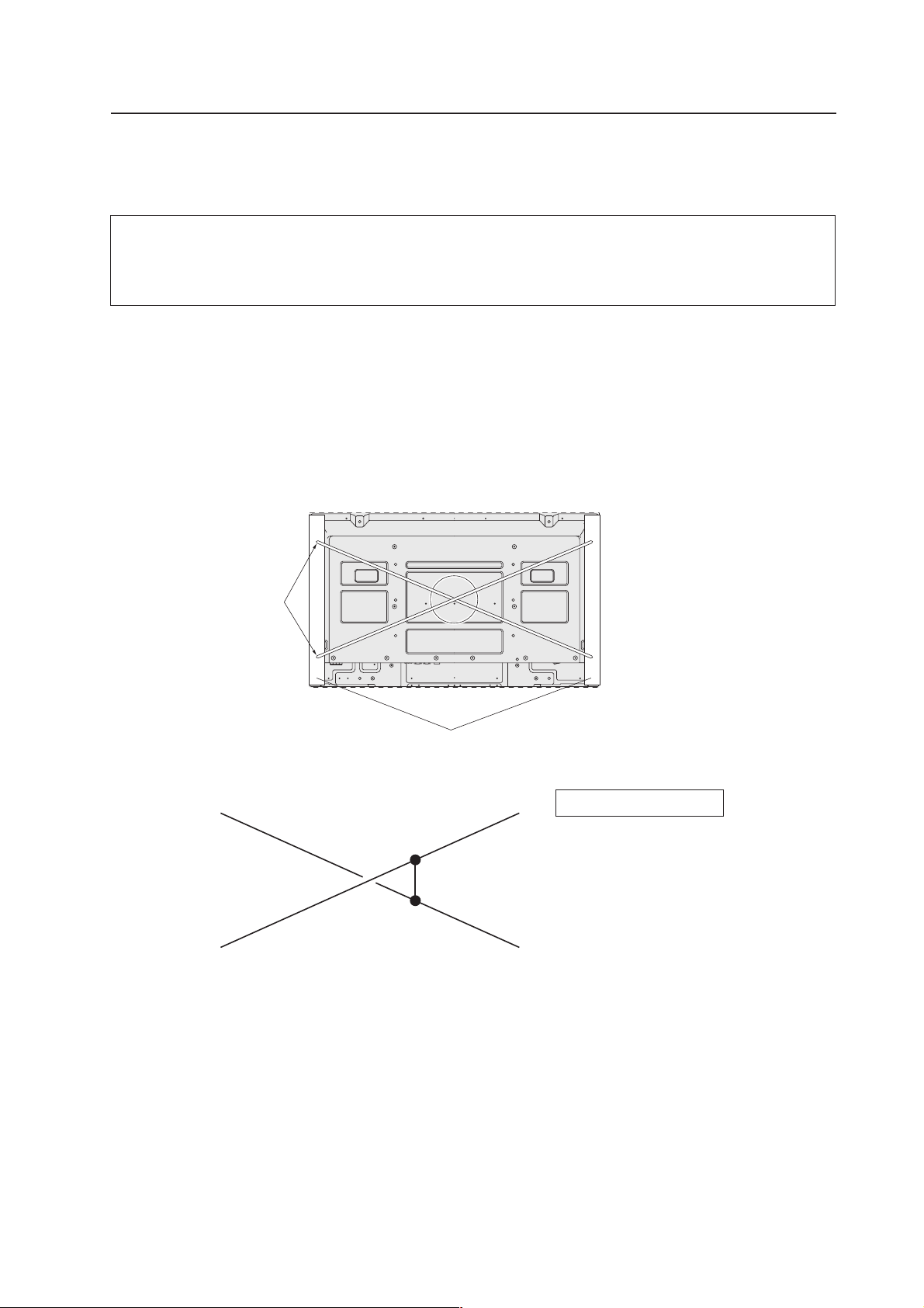
3.2.4 Mounting surface warping
The display incorporates glass. Before mounting the panel using hardware other than that provided by Pioneer, perform
the following checks to confirm that the display is free from warps exceeding 1 mm*.
Regarding the 1 mm limit:
The panel frame may have a warp of up to 3 mm. If the total warp (the warp of the frame plus the warp of the
mounting surface) exceeds 4 mm then the glass in the display may experience excessive stress. To ensure that
the total warp is less than 4 mm, verify that the warp of the mounting surface is less than 1 mm.
φ
1 Referring to the illustration below, diagonally extend string (maximum diameter
mount openings. Strings should be completely free of slack.
2 Measure the clearance (L) between the strings where they cross.
Distortion is expressed by: [Distortion] = L × 2.
3 If L is found to be 0, pass the strings through the other bolt mount openings then repeat the measurements. Any
value of L greater than 0 indicates the presence of distortion. If the measured value in both cases is 0, the
distortion is negligible.
0.1- mm) through the bolt
Mount bolt holes
A
String
String
C
A
Plasma Display Mount Surface (Mount Brackets)
Magnified view of section A
D
F
L
E
Point E is the center point of string
segment A-B.
Point F is the center point of string
segment C-D.
Clearance between points E and F = L
(Points E and F are shown displaced
for illustrative purposes).
B
25
Page 26
Installation Conditions
[427CMX]
3.3 Installation Conditions (PDP-427CMX)
3.3.1 Heat dissipation
This unit has openings for effective ventilation. Vent locations are marked by arrows in the illustration below. The
direction of the arrows shows the direction of airflow. To allow proper dissipation of heat from the unit, do not
cover any of these openings.
(Unit : mm)
127.7 74.5
36.3 34.7
24.564.3
43.1 24.8
52.6 39.8
98.8 114.5
372.4
264.5
49.742.4
Fan Fan
A A A A A
72.4 72.4 52.472.452.4
39.9 52.2
374.5
414.5
137.381.3137.3 81.3
98.8114.5
24.564.3
202.8
44.5
124.5
137.7
127.7 74.5
43.1 24.8
52.6149.8
In a standard installation, two fans and part A draw hot air from the unit. All openings not assisted by fans serve as
air inlets. If the unit is hung from or embedded into a wall, special operating temperature limits and other limitations
may apply. Refer to section “3.6 Special Installation (PDP-427CMX)” (pg. 55) for more information.
26
Page 27
[427CMX]
Installation Conditions
3.3.2 Calculating heat quantity
As a courtesy to our customers, we have included the power formula for calculating air conditioning needs.
For power consumption, allow 320 W = 320 VA per unit.
Since most of the power consumed is transformed into heat, power consumption may be regarded as roughly equal to
generated heat.
1 Conversion to calories
[W] × 0.86 = [kcal/h]
Heat generated per display: 320 W × 0.86 = 275 kcal/h
2 Conversion to British Thermal Units
[W] × 3.41 = [BTU/h]
Heat generated per unit: 320 W × 3.41 = 1019 BTU/h
3.3.3 Product mounting holes
We recommend using mounting hardware available from Pioneer. If you use other mounting hardware, mount the
hardware to the unit using the M8-bolt holes provided in the unit. Tighten the bolts with a torque between 50 kg/cm and
80 kg/cm. Applying a torque beyond these limits may lead to internal component failure.
Locations of usable mounting holes are shown below.
a Holes (6 places)
b Holes (4 places)
This unit
12 mm to 18 mm
Side view diagram
Attaching
surface
Installation
bracket etc.
a hole
Bolt
12 mm to 18 mm
b hole
Bolt
b hole
b hole
a holes
Vent (fan)
Center line
Rear view diagram
b hole
a holes
b hole
Always use a minimum of 4 mounting holes that are evenly distributed on opposite sides of both the horizontal
and vertical center lines.
Use bolts that can be driven 12 mm to 18 mm into holes “a” and from 12 mm to 14 mm into holes “b” as shown
in the Side View above.
Do not block or cover vents on the rear panel.
Take precautions to prevent the walls from being soiled by the Plasma Display’s exhaust outlets.
This unit incorporates glass components. Install only on flat surfaces.
Always turn every bolt by hand two to three times then check to make sure the bolt is straight.
You may tighten using a tool but do not over-tighten the bolts.
Do not use
loctight
or similar bonding products.
Please use M8 (P=1.25) bolts. DO NOT use any other type of bolt.
The panel is attached using M8x6 or M8x4, but it can also be attached using M4x8.
For details, see the following page.
27
Page 28
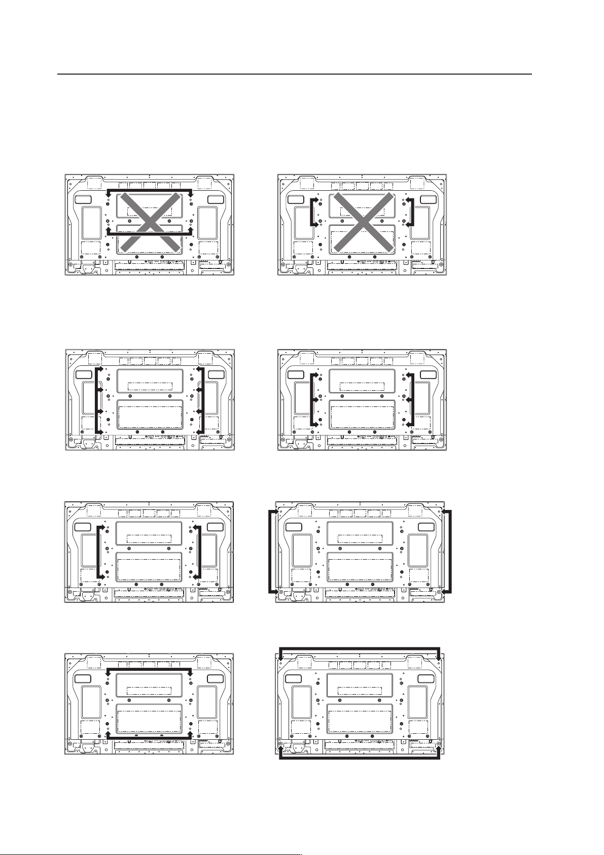
Installation Conditions
This unit is designed to be mounted using four bolt holes. For additional safety, we recommend securing it at four, six
or eight points on opposite sides of the horizontal and vertical center lines, as shown in the drawing below. Methods
shown with a large “X” must not be used.
Poor methods for securing
Suggested methods for securing
[427CMX]
Secured at eight points
*Attach using M4x8.
Secured at four points
*Attach using M8x4.
Secured at six points
*Attach using M8x6.
Secured at four points (with mounting hardware attached to the sides)
*Attach using M8x4.
(Take proper precautions to prevent pinching the power cord or signal cables.)
28
Page 29
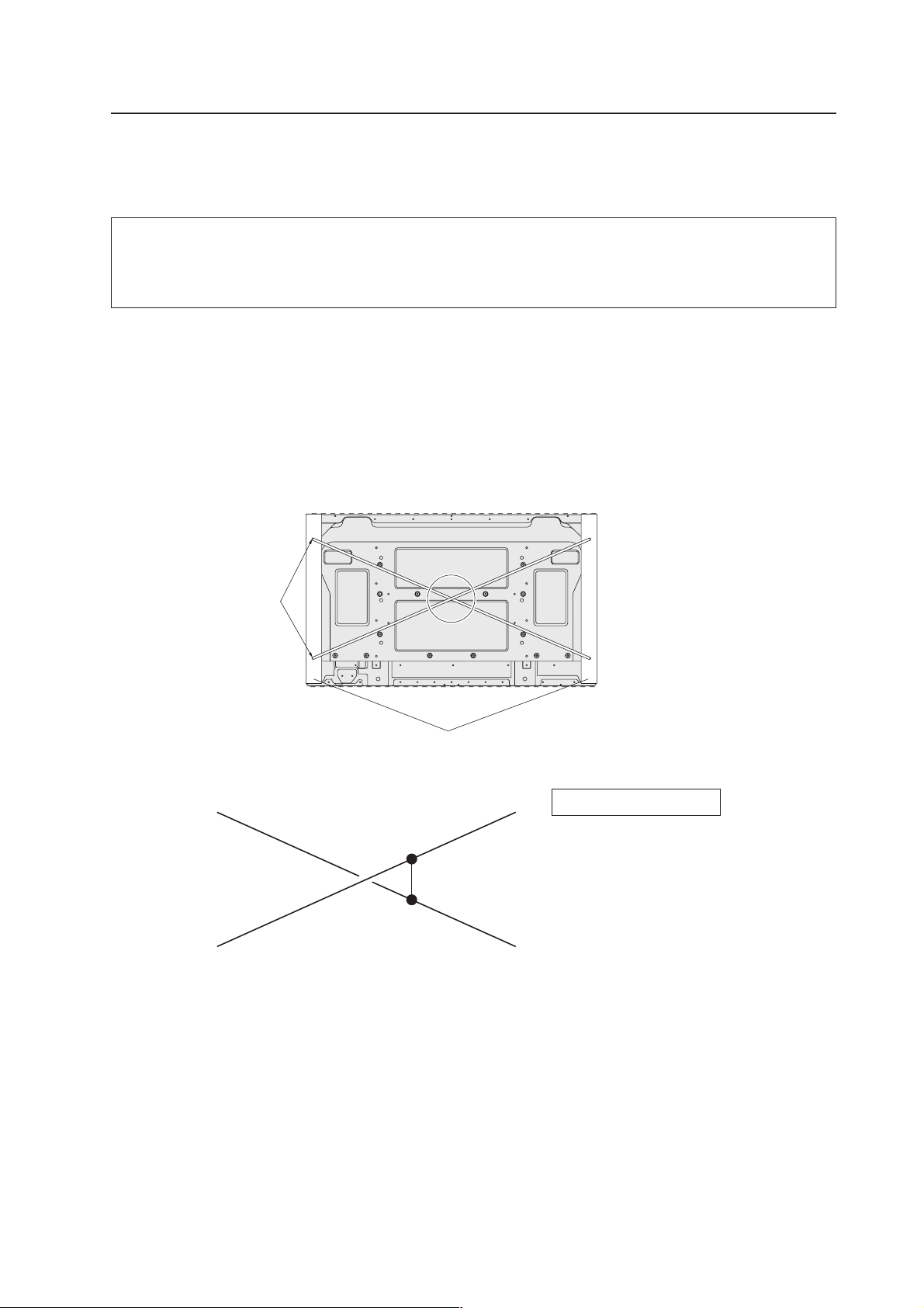
[427CMX] Installation Conditions
3.3.4 Mounting surface warping
The display incorporates glass. Before mounting the panel using hardware other than that provided by Pioneer, perform
the following checks to confirm that the display is free from warps exceeding 1 mm*.
Regarding the 1 mm limit:
The panel frame may have a warp of up to 3 mm. If the total warp (the warp of the frame plus the warp of the
mounting surface) exceeds 4 mm then the glass in the display may experience excessive stress. To ensure that
the total warp is less than 4 mm, verify that the warp of the mounting surface is less than 1 mm.
φ
1 Referring to the illustration below, diagonally extend string (maximum diameter
mount openings. Strings should be completely free of slack.
2 Measure the clearance (L) between the strings where they cross.
Distortion is expressed by: [Distortion] = L × 2.
3 If L is found to be 0, pass the strings through the other bolt mount openings then repeat the measurements. Any
value of L greater than 0 indicates the presence of distortion. If the measured value in both cases is 0, the
distortion is negligible.
0.1- mm) through the bolt
Mount bolt holes
A
String
String
C
A
Plasma Display Mount Surface (Mount Brackets)
Magnified view of section A
D
F
L
E
Point E is the center point of string
segment A-B.
Point F is the center point of string
segment C-D.
Clearance between points E and F = L
(Points E and F are shown displaced
for illustrative purposes).
B
29
Page 30
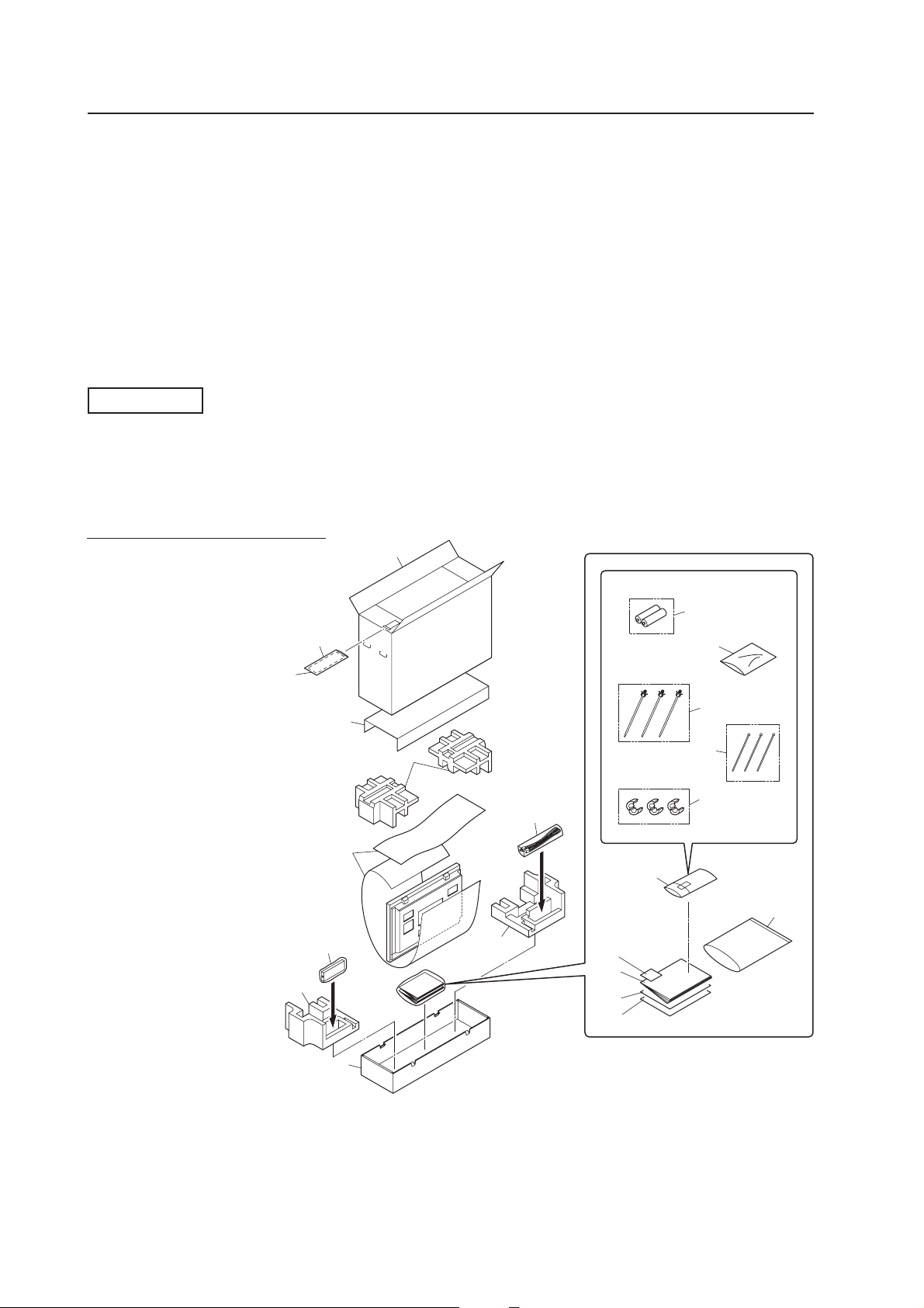
Installation Procedures
[507CMX : 427CMX]
3.4 Installation Procedures
3.4.1 Transportation precautions
• Once the shipping container is opened, transporting the unit in its packaging should be handled by two or more
people. To avoid injury or damage, do not lift the package by its packing bands.
• When transporting or storing the unit, always position it vertically - never horizontally. Horizontal transportation or
storage invalidates the product warranty.
• In transportation or storage of products in original packing, never stack more than three units high.
• For transportation or storage, observe the warnings and instructions on the upper face of the carton.
• The Plasma Display is made of glass. Please handle the panel carefully to prevent it from being damaged.
3.4.2 Unpacking
PDP-507CMX
The original packing material can be re-used to safely ship the Plasma Display. When repacking, it is important to use
the material in the same way as when the unit originally shipped. Failure to pack the panel correctly can damage the
Plasma Display.
1) Packing specifications; 1340 mm (W) × 900 mm (H) × 365 mm (D), 50 kg
Ref. No. Terms
1 Upper Carton
2 Carton
3 Reinforce Pad
4 Pad
5 Pad
6 Mirror Mat
7 Power Cord
16
8 Remote Control Unit
9 Dry Cell Battery (R6P, AA)
10 Vinyl Bag’s Assembly
11 Wiping Cloth
12 Operating Instructions
13 Caution Sheet
14 Caution Sheet
15 Warranty Card
16 Warranty Card Vinyl Pouch
17 Vinyl Bag (S)
18 Speed Clamp
19 Binder
15
3
6
1
9
17
18
4
7
10
19
20
21
20 Ferrite Core (S)
21 Vinyl Bag
30
8
5
2
5
11
12
13
14
Page 31

[507CMX : 427CMX]
Installation Procedures
PDP-427CMX
The original packing material can be re-used to safely ship the Plasma Display. When repacking, it is important to use
the material in the same way as when the unit originally shipped. Failure to pack the panel correctly can damage the
Plasma Display.
1) Packing specifications; 1177 mm (W) × 767 mm (H) × 354 mm (D), 38 kg
Ref. No. Terms
1 Upper Carton
2 Carton
3 Reinforce Pad
4 Pad
5 Pad
6 Mirror Mat
7 Power Cable Case
8 Accessory Case
9 Power Cord
10 Remote Control Unit
11 Dry Cell Battery (R6P, AA)
12 Remote Control Unit Holder
13 Display Stand
14 Vinyl Bag’s Assembly
15 Wiping Cloth
16 Operating Instructions
17 Warranty Card Vinyl Pouch
18 Caution Sheet
19 Caution Sheet
20 Warranty Card
21 Vinyl Bag
22 Bag
23 Screw Set
24 Speed Clamp
25 Nylon Binder
1
3
4
18
6
9
7
5
5
17
22
23
24
25
26
27
14
8
15
16
19
5
20
12
21
13
26 Ferrite Core (S)
27 Ferrite Core (L)
2
11
10
31
Page 32

Installation Procedures
2) Unpacking procedures
1 Remove the packing bands.
2 Slowly lift and remove the upper carton.
3 Lift and remove the carton cover.
4 Remove the pads.
5 Remove the accessory and power cord cases.
6 Remove the unit (requires two or more people).
3) Transportation of the unpacked unit.
If it needs to be moved, the unit should be lifted by two or more people.
Caution
• Never move the unit by dragging it along the floor.
• Move the unit slowly, taking care to prevent scraping or striking the delicate
front protective panel.
• In order to prevent adhesion of dust, remove the protective film only after
all work and preparations for the installation site, including clean-up following
unpacking, are complete.
• When moving the display, it should always be carried by two people holding
the rear handles in the manner shown.
[507CMX : 427CMX]
No!
Never attempt to move the Plasma Display by holding only one of the handles.
3.4.3 Mounting on the attachment stands (PDP-427CMX only)
(See " 4.3 Installation of the Attachment Stand (pg. 78)" for instructions on permanent installation.)
Insert the stand into A and A' on the back of the main unit and anchor it with the attached washers and bolts. After
manually tightening the bolts, completely tighten them with the attached tools.
When doing this installation with the main unit on its side, align the bolts while pushing the stand.
This method should be a temporary setup pending proper installation. When installing the stand, consult “4.3 Installation
of the Attachment Stand” (pg. 78) for more information.
Placing the screen on the stands is only a temporary step before proper installation. We cannot guarantee against
damage if the display falls from someone bumping it while in the stands.
A A'
32
Page 33

Installation Procedures[507CMX : 427CMX]
3.4.4 Re-packing (re-packing and re-shipping are not covered by the warranty)
If the unit needs to be re-packaged, observe the following guidelines.
• Refer to the unpacking instructions in section “3.4.2 Unpacking” (pg. 30 to 32). Pack the unit by reversing the
unpacking procedure. There is a front and back to the miller mat. Place the shiny film surface facing out and the
soft surface facing in towards the display glass.
• Restore all accessories to their original locations. Secure with adhesive tape to prevent damage during
transportation.
• Do not re-package and ship if the packing material is damaged.
3.4.5 Wiring
1) Connecting the power cable
• Refer to the “ Power Cord Connection ” section in the operating instructions.
• For power source specifications, refer to “3.1 Installation Site Requirements, Section 11) Power requirements”
(pg. 21) earlier in this document.
2) Connecting signal cables
• Refer to the operating instructions shipped with the unit for information on how to connect a PC or audio
device.
• Precautions when using long connecting signal cables
-- Use coaxial cables. For video signals use 3 C-2 V cables for lengths up to 15 meters and 5 C-2 V cables for
lengths up to 30 meters. Because computer signals are more likely to degrade than video signals, even if the
cable is shorter than 15 m, the use of 5 C-2 V coaxial multi-cables (5BNC) is recommended. You can also
improve signal quality by minimizing cable length.
-- Video cables plugged into video inputs and outputs close to dimmers, neon signs, air-conditioning units, or
cables for wired broadcasts may occasionally corrupt images.
3) Processing wires
• For permanent or long-term installation, please select cables of the correct length and consider the entire wiring
route. This is not as important for temporary or short-term installations such as at special events.
• Arrange and secure cables so that they are not subject to pinching or physical force. For temporary installations,
securing cables with string is adequate. For permanent installations, secure by more reliable means.
33
Page 34

[507CMX : 427CMX]
4) Arranging and securing cables with speed clamps and bead bands
Fasten cables using the supplied speed clamps.
Once speed clamps are fastened, they are
not easily removed.
* As viewed from the rear of the display.
2
1
Installation Procedures
1. Organize cables together using the provided
speed clamps.
Insert 1 into an appropriate hole on the rear of the
unit then snap 2 into the back of 1 to fix the clamp.
Speed clamps are designed to be difficult to undo
once in place. Please attach carefully.
To attach the speed clamps to the main unit
Use the holes marked with the & border shown below as
needed.
2. Bunch separated cables together and secure them
with the provided bead bands.
Do not allow excessive stress to be placed on the
ends of cables.
Note
Cables can be routed to the right or left.
* As viewed from the rear of the display. (PDP-507CMX)
* As viewed from the rear of the display. (PDP-427CMX)
To remove speed clamps
Using pliers, twist the clamp 90° and pull outward.
In some cases, the clamp may have deteriorated over
time. Removed speed clamps may not be re-usable.
34
Page 35

[507CMX] Special Installation (Mounting to fittings)
3.5 Special Installation (PDP-507CMX)
The unit can be hung from or embedded in a wall. However, some installations impose additional limitations on
operating temperatures and other factors.
Examine installation methods and the ambient conditions for your installation site. Refer to sections “3.1 Installation
Site Requirements” (pg. 20), ”3.2 Installation Conditions (PDP-507CMX)” (pg. 22), and “3.4 Installation Procedures”
(pg. 30) in this manual.
Measurements discussed in this manual assume the following conditions:
• A 100 % white input is supplied.
• Sufficient aging has been completed.
Make all measurements under identical conditions. The aging period required for correct measurement
is about two and a half hours, depending on the time available at the installation site.
3.5.1 Mounting to fittings
Observe the following guidelines when mounting the unit to fittings.
Notes 2 to 8 apply to all cases of mounting to fittings.
1 Remove any objects from around the panel within a distance of
300 mm.
2 Any unit deformation/warping occurring as a result of installation
should be less than 4 mm.
3 Never block or cover vents or other openings aside from those
shown as blocked in the illustrations on the following page.
4 The fittings should have a thickness of less than 20 mm.
(This limit does NOT apply to fitting in examples 1, 4, 6, and 7 on
the following page.)
5 L-shaped fittings should have a thickness of less than 100 mm.
6 The strength of the fittings should be adequate to bear the weight
of the display.
7 Take precautions to avoid sharply bending the power cable.
8 If necessary, remove the handles. When reinstalling the handles,
completely tighten the screws for safety.
✩ Operating environment for standard installation
• Ambient Temperature: 0 °C to 40 °C (examples 1 to 4)
✩ Operating environment for vertical installation
(*1)
• Ambient Temperature: 0 °C to 40 °C (vertical installation:
examples 5 to 8)
✩ Operating temperatures for Upside-Down Installations
(*1, *2)
• Ambient Temperature: 0 °C to 35 °C (examples 1 to 4)
The operating temperature restrictions for the speaker system (PDPS53-LR) are the same regardless of whether installation is horizontal
or vertical.
*1
For this installation, set the ‘FAN CONTROL’ to ‘MAX’ as shown in “5.4.3
Adjustment and Setting in the Integrator Mode 14) Cooling Fan Control
Setting (pg. 235)”.
*2
When INPUT2 has been selected, use input compatible signal up to
1280x1024 (60 Hz) at ambient temperature condition of 0 °C to 35 °C.
Maximum allowable deformation/
warping is 4 mm.
Less than
20 mm
(No thickness limitations in examples 2
and 4 on the following page.)
Less than
20 mm
(No thickness limitations in examples 2
and 4 on the following page.)
Less than
100 mm
4 mm MAX
L-shaped fitting
Arrange the power
cable so that minimum
stress is placed on it.
Note
When a video card other than PDA-5003/PDA-5004 is used, the operating
temperature conditions given above may vary. Check the video card
operating instructions for the conditions.
35
Page 36

[507CMX]Special Installation (Mounting to fittings)
Standard installation
Example 1
Example 3
(In cases where top and bottom are reversed)
35 mm or
less
35 mm or less
Example 2
Example 4
Vertical installation
Example 5
Attach so that
the fan is on
the left side
when viewed
from the rear.
Example 7
35 mm or
less
35 mm or less
Example 6
Example 8
36
Page 37

[507CMX]
Special Instruction (Hanging on the wall)
3.5.2 Hanging on the wall
Carefully read the following imformation before attempting to hang the unit on a wall. Take note of the various limitations
specified in this section. Mount the unit so that twisting, bending, or any other warping does not exceed 4 mm.
Shaded areas indicate attachment points for mounting hardware.
: Thermometer (temperature measurement point)
1222
A
B
50
90
C
25 736
D
Operating temperature restrictions
✩ Standard single-unit installation
Distance from wall (A) BC DAmbient temperature
50 mm or less 300 mm or more 300 mm or more 300 mm or more 0 °C to 35 °C
50 mm or more 100 mm or more 50 mm or more 50 mm or more 0 °C to 40 °C
✩ Horizontal/vertical, left/right reverse installation (Note that only Examples 2 and 3 apply in cases
where the top and bottom are reversed)
* Regardless of the distance between the Plasma Display and the wall, the unit must be installed to allow
free air flow (no obstructions within a distance of 300 mm from the unit) around the panel.
Distance from wall (A) BC DAmbient temperature
50 mm or more 300 mm or more 300 mm or more 300 mm or more 0 °C to 35°C
✩ Requirements when used with PDP-S53-LR speaker system
When installed as a single unit, all requirements are the same as those listed above for horizontal/
vertical, left/right reverse installations. However, the figures listed above indicate the distance
between the speakers and the wall.
D
Note
Different temperature restrictions apply to the PDK-5011 and PDK-WM01. Refer to “4.6 Tilt Mount Unit PDK-5011”
(pg. 104) and “4.7 Wall Mount Unit PDK-WM01” (pg. 110). For a wall-mount installation, allow adequate space (a
clearance of 300 mm or more) above, below, and to each side of the panel.
37
Page 38

[507CMX]Special Installation (Hanging on the wall)
Methods of Securing: Basic methods of securing the panel to a wall are shown below. Avoid blocking or covering
areas aside from those indicated by
used. Before attaching the unit to fittings, double-check that the thickness and height of the
fittings and the number of fixing bolts is correct.
(Also refer to “3.5.1 Mounting to fittings” (pg. 35).)
. The method indicated by a large “X” must not be
Note
Heated air is drawn from the interior of the unit by fans. Before installation, consider the heat resistance of the wall
or other surface behind the unit. Exhaust temperatures can be 30 °C higher than the outside temperature.
Note
For wall-mounting, do not bundle the cables in a way that block vents.
300 mm or
more
300 mm or
more
Flush-wall installation
(distance between unit and wall
less than 50 mm)
Requirements :
• Free air flow (With no obstructions
within a distance of 300 mm from
the unit’s sides, top and bottom)
• Temperature of 0 °C to 35 °C
100 mm or more
50 mm or
more
50 mm or more
Ex.: Installation requirements when
installed in wall recess
50 mm or
more
Wall-mounted installation
(distance between unit and wall
greater than 50 mm)
Requirements :
• Free air flow (With no obstructions within
a distance of 300 mm from the unit)
around all four sides of the unit is not
necessarily required when the unit is
installed at a distance of greater than 50
millimeters away from the wall.
* However, in such cases, the unit may not
be placed behind a glass panel or any
other obstruction which would create an
enclosed space.
• Temperature of 0 °C to 40 °C
Panting net
100 mm or more
100 mm or more
Ex.: Installation when covered with a
Panting net
Wall-embedded installation
(i.e., installation in closed space)
(distance between unit and wall
greater than 50 mm)
Requirements :
• See “3.5.3 Embedding in the wall” (pg.
39) for installation requirements.
• Temperature of 0 °C to 40 °C
100 mm or more
100 mm or more
38
Page 39

[507CMX] Special Installation (Embedding in the wall)
3.5.3 Embedding in the wall
Carefully read the following imformation before trying to embed the unit in a wall. Observe all the limitations specified
below.
Be sure to mount the unit so that twisting, bending, or other deformation of the unit does not exceed 4 mm.
(1) Embedding in walls with space provided behind the unit (no obstructions within a distance of 300 mm from the
back surface of the unit).
A
X (Front of the unit)
A
Y (Rear of the unit)
A
<Viewed from Above>
✩ Operating Temperature Restrictions
Temperature in space X and Y
A: 0 mm to 370 mm 0 °C to 40 °C
* The same operating temperature restrictions apply to the speaker system (PDP-S53-LR).
✩ Operating Temperature Restrictions for Upside-Down Installations
* Upside-down mounting is unavailable when embedding this device in a wall.
A
<Viewed from the Right Side>
Methods of Securing: Basic methods of securing are shown below. Avoid blocking or covering areas aside from those
indicated by
Before attaching the unit to fittings, double-check that the thickness and height of the fittings,
and the number of bolts is correct.
(Also refer to “3.5.1 Mounting to fittings” (pg. 35).)
.
39
Page 40

[507CMX]Special Installation (Embedding in the wall)
Temperature Measurement Points (Illustration for reference purposes)
: Thermometer (temperature measurement point)
50 mm 50 mm
• Make measurements at a distance of 50 mm from the unit without directly subjecting the thermometer to fan
exhaust.
• For spaces where temperature fluctuations are likely, gather additional measurement points for adequate data.
40
Page 41

[507CMX]
Special Installation (Embedding in the wall)
(2) Embedding in walls with no space provided behind the unit.
Panting (Punching) net (numerical aperture 50 % or over)
100 mm or
50 mm or
more
more
more
100 mm or
more
100 mm or
100 mm or
more
Cation : Due to possible heat issues, we do not recommend installing the panel in narrow, enclosed areas.
✩ Operating Temperature Restrictions
• Ambient temperature: 0 °C to 40 °C
• The same operating temperature restrictions apply to the speaker system (PDP-S53-LR).
✩ Operating Temperature Restrictions for Upside-Down Installations
* Upside-down mounting is unavailable when embedding this device in a wall.
Methods of Securing: Basic methods of securing are shown below. Avoid blocking or covering areas aside from those
indicated by . The methods indicated by a large “X” must not be used.
Before attaching the unit to fittings, double-check that the thickness and height of the fittings
and the number of bolts is correct.
(Also refer to “3.5.1 Mounting to fittings” (pg. 35).)
Installation is not possible
41
Page 42

[507CMX]Special installation (When the display is put in a box)
3.5.4 When the display is put in a box
Operating this display in confined spaces is not recommended.
• If the display is to be used in a confined space, observe the following conditions shown in the drawing below:
A ≥ 50
B ≥ 50
C ≥ 10
D ≥ 50
Use a mesh with aperture efficiency of 50 % or more.
If hot air remains in the enclosed space, the temperature may rise causing a malfunction or fire. As a precaution, the
inner wall should have sufficient heat resistance or fire resistance.
✩ Usage temperature conditions (BOX air temperature)
• Ambient temperature: 0 °C to 35 °C
: Thermometer
(temperature measurement point)
Exhaust side Intake side
AA
Outside air temperature
measuring point
10 mm
A ≥ 50
B ≥ 50
C ≥ 10
D ≥ 50
BB
10 mm
Rear view (the following area should be made of mesh)
A+
50 mm
A+
50 mm
800 mm or more
800 mm or more
42
CD
Mesh with aperture efficiency
of 50 % or more
A+
50 mm
B+
30 mm
or more
100 mm
or more
100 mm
B+
A+
50 mm
50 mm
Page 43

[507CMX] Special Installation (Ceiling suspension with wires)
3.5.5 Ceiling suspension (with wires)
When suspending with wire, attach the unit either at rows A and B or at rows C and D to keep it from warping. In
addition, the unit must be attached
sides of the vertical and horizontal center lines.
at four or more points, with these points distributed symmetrically on opposite
A B
Attach so that the fan is on the left
side when viewed from the rear.
C
C
A
D
B
D
When suspending from a ceiling with wire, use the brackets shown below to prevent concentrating loads on the upper
two fixing points.
For additional safety, secure the wires to separate fittings or parts of the ceiling.
Use mounting screws of material stronger than soft steel and use hexagonal bolts.
Use wires adequate for the combined weight of the panel and the weight of the support brackets.
No!
When installing the Plasma Display, DO NOT use the handles as means of hanging the display.
Wires
Wires
Screws
Brackets
Brackets
Screws
✩ Operating environment for standard installation
• Ambient Temperature: 0 °C to 40 °C
✩ Operating environment for vertical installation
• Ambient Temperature: 0 °C to 40 °C
✩ Operating temperatures for Upside-Down Installations
(*1)
(*1, *2)
• Ambient Temperature: 0 °C to 35 °C
*1
For this installation, set the ‘FAN CONTROL’ to ‘MAX’ as shown in “5.4.3 Adjustment and Setting in the Integrator Mode 14)
Cooling Fan Control Setting” (pg. 235).
*2
When INPUT2 has been selected, use input compatible signal up to 1280x1024 (60 Hz) at ambient temperature condition of 0 °C
to 35 °C.
43
Page 44

[507CMX]Special Installation (Ceiling suspension with wires)
Methods of Securing: Basic methods of securing are shown below. Avoid blocking or covering areas aside from those
indicated by . The methods indicated by a large “X” must not be used.
Before attaching the unit to fittings, double-check that the thickness and height of the fittings,
and the number of bolts is correct.
(Also refer to “3.5.1 Mounting to fittings” (pg. 35).)
Vertical suspension
Attach so that the fan is
on the left side when
viewed from the rear.
Installation is not possible
Installation is not possible
44
Page 45

[507CMX] Special Installation (Hanging on the wall lengthwise)
3.5.6 Hanging on the wall lengthwise
Carefully read the following imformation before attempting to mount the unit on the wall. Observe the various limitations
specified below.
Be sure to mount the unit so that twisting, bending, or any other deformation does not exceed 4 mm.
Shaded areas indicate attachment points for mounting hardware.
: Thermometer (temperature measurement point)
Attach so that the fan is on the left
side when viewed from the rear.
52.552.5
B
1222
Avoid blocking or
covering this area
on the upper and
lower sides.
21.6
736
10
A
93.4
25
DD
C
10
✩ Operating Temperature Restrictions
Distance from wall (A) BC DAmbient temperature
(*1)
50 mm or more 100 mm or more 50 mm or more 50 mm or more 0 °C to 35 °C
*1
For this installation, set the ‘FAN CONTROL’ to ‘MAX’ as shown in “5.4.3 Adjustment and Setting in the Integrator
Mode 14) Cooling Fan Control Setting” (pg. 235).
45
Page 46

[507CMX]Special Installation (Hanging on the wall lengthwise)
Methods of Securing: Basic methods of securing are shown below. Avoid blocking or covering areas aside from those
indicated by . The method indicated by a large “X” must not be used.
Before attaching the unit to fittings, double-check that the thickness and height of the fittings
and the number of bolts is correct.
(Also refer to “3.5.1 Mounting to fittings” (pg. 35).)
Installation is not possible
Note
Heat air is drawn from the interior of the unit by fans. Before installation, consider the heat resistance of the wall or
other surface behind the unit. Exhaust temperatures can be 30 °C higher than the outside temperature.
Note
For wall-mounting, do not bundle the cables in a way that block vents.
Installation is not possible
46
Page 47

[507CMX]
Special Installation (Place product upright and flush, embedded in the wall)
3.5.7 Place product upright and flush into wall (embedding in the wall)
Carefully read the following instructions before trying to embed the unit in a wall. Observe all the limitations specified
below.
Be sure to mount the unit so that twisting, bending, or other deformation of the unit does not exceed 4 mm.
(1) Embedding in walls with space provided behind the unit (with no obstructions within a distance of 300 mm
from the back surface of the unit)
AA
A
X (Front of the unit)
Y (Rear of the unit)
<Viewed from Above>
A
<Viewed from the Right Side>
✩ Operating Temperature Restrictions
Temperature in space X and Y
A: 0 mm to 370 mm 0 °C to 40 °C
*1
For this installation, set the ‘FAN CONTROL’ to ‘MAX’ as shown in “5.4.3 Adjustment and Setting in the Integrator Mode 14)
Cooling Fan Control Setting” (pg. 235).
(*1)
47
Page 48

Special Installation (Place product upright and flush, embedded in the wall)
[507CMX]
Methods of Securing: Basic methods of securing are shown below. Avoid blocking or covering areas aside from those
indicated by . The methods indicated by a large “X” must not be used.
Before attaching the unit to fittings, double-check that the thickness and height of the fittings
and the number of fixing bolts is correct.
(Also refer to “3.5.1 Mounting to fittings” (pg. 35).)
Attach so that the fan is
on the left side when
viewed from the rear.
Installation is not possible
Installation is not possible
48
Page 49

[507CMX]
Special Installation (Place product upright and flush, embedded in the wall)
(2) Embedding in walls with no space provided behind the unit
Attach so that the
fan is on the left
side when viewed
from the rear.
100 mm or
more
100 mm or
more
more
100 mm or
Panting (Punching) net
(numerical aperture 50 %
or over)
more
100 mm or
50 mm or
more
Cation : Due to possible heat issues, we do not recommend installing the panel in narrow, enclosed areas.
✩ Operating Temperature Restrictions
(*1)
• Ambient temperature: 0 °C to 35 °C
*1
For this installation, set the ‘FAN CONTROL’ to ‘MAX’ as shown in “5.4.3 Adjustment and Setting in the Integrator Mode 14)
Cooling Fan Control Setting” (pg. 235).
49
Page 50

Special Installation (Place product upright and flush, embedded in the wall)
[507CMX]
Methods of Securing: Basic methods of securing are shown below. Avoid blocking or covering areas aside from those
indicated by . The methods indicated by a large “X” must not be used.
Before attaching the unit to fittings, double-check that the thickness and height of the fittings
and the number of bolts is correct.
(Also refer to “3.5.1 Mounting to fittings” (pg. 35).)
Attach so that the fan is
on the left side when
viewed from the rear.
Installation is not possible
Installation is not possible
50
Page 51

[507CMX]
Special Installation (Installed facing upward)
3.5.8 Installed facing upward
(1) When installed on top of a horizontal surface <an open space other than a horizontal surface>
Horizontal surface
50 mm or more
Horizontal surface
✩ Operating Temperature Restrictions
(*1)
• Ambient temperature: 0 °C to 35 °C
• The same operating temperature restrictions apply to the speaker system (PDP-S53-LR).
*1
For this installation, set the ‘FAN CONTROL’ to ‘MAX’ as shown in “5.4.3 Adjustment and Setting in the Integrator Mode 14)
Cooling Fan Control Setting” (pg. 235).
Methods of Securing: Basic methods of securing are shown below. Avoid blocking or covering areas aside from those
indicated by . The methods indicated by a large “X” must not be used.
Before attaching the unit to fittings, double-check that the thickness and height of the fittings
and the number of bolts is correct.
(Also refer to “3.5.1 Mounting to fittings” (pg. 35).)
Installation is not possible
51
Page 52

Special installation (Installed facing upward)
[507CMX]
(2) When the Plasma Display is in a confined space
Operating this display in confined spaces is not recommended.
• If the display is to be used in confined spaces, observe the following conditions shown in the drawing below:
A ≥ 50
• If heat remains in the enclosed space, the temperature may rise causing a malfunction or fire. As a precaution, the
inner wall should have sufficient heat resistance or fire resistance.
• Leave a space at least 10 mm wide when installing glass etc. on the front of the Plasma Display.
✩ Usage temperature conditions
(*1)
• Ambient temperature: 0 °C to 35 °C (Outside air temperature)
• Space enclosed by the back surface of the Plasma Display: 0 °C to 35 °C (Use a fan etc. to discharge air to
maintain this temperature range.)
*1
For this installation, set the ‘FAN CONTROL’ to ‘MAX’ as shown in “5.4.3 Adjustment and Setting in the Integrator Mode 14)
Cooling Fan Control Setting” (pg. 235).
: Thermometer (temperature measurement point)
Outside air temperature
measuring point
Outside air
temperature
measuring point
150 mm
A ≥ 50
Enclosed space air
temperature measuring
point
10 mm
A
50 mm
Enclosed space air temperature
measuring point
Note
When installing the Plasma Display facing upwards, do not place anything on top of it nor apply any load on it from
above.
52
Page 53

[507CMX]
Special installation (Horizontal connections)
3.5.9 Horizontal connections
While the display is designed to accommodate side-by-side installations, keep in mind that specific installation
configurations may affect ventilation. Observe the following requirements:
1 Installation of up to two units (Horizontal connection)
The following table lists the operating temperature conditions when installing more than one panel. Use the units
under conditions that keep the outside atmosphere in this range.
A
Unit A Unit B
✩ Operating Temperature Restrictions
Distance from wall (A) Ambient temperature
50 mm or more 0 °C to 40 °C
2 Installing three or more units (Horizontal connection)
The following table lists the operating temperature conditions. Use the units under conditions that keep the
outside atmosphere in this range.
A
Unit A Unit B
Unit C
✩ Operating Temperature Restrictions
Distance from wall (A) Ambient temperature
50 mm or more 0 °C to 40 °C
53
Page 54

Special installation (Multiple)
[507CMX]
3.5.10 Multiple
While the display is designed to accommodate side-by-side installations, keep in mind that specific installation
configurations may affect ventilation. Observe the following requirements:
1 Installing multiple (Two vertical units)
The following table lists the operating temperature conditions when installing more than one panel. Use the units
under conditions that keep the outside atmosphere in this range.
A
Partition
Unit A Unit B Unit C
In case of lateral connections, ensure that left and right partitions are provided.
To prevent heat venting from one video wall plasma panel into another panel, each display must
be oriented in the same direction.
In the above example, each panel is shown with the Pioneer logo at the bottom.
✩ Operating Temperature Restrictions
Distance from wall (A) Ambient temperature
50 mm to 300 mm or less 0 °C to 35 °C
300 mm or more 0 °C to 40 °C
54
Page 55

[427CMX] Special Installation (Mounting to fittings)
3.6 Special Installation (PDP-427CMX)
The unit can be hung from or embedded in a wall. However, some installations impose additional limitations on
operating temperatures and other factors.
Examine installation methods and the ambient conditions for your installation site. Refer to sections “3.1 Installation
Site Requirements” (pg. 20), ”3.3 Installation Conditions (PDP-427CMX)” (pg. 26), and “3.4 Installation Procedures”
(pg. 30) in this manual.
Measurements discussed in this manual assume the following conditions:
• A 100 % white input is supplied.
• Sufficient aging has been completed.
Make all measurements under identical conditions. The aging period required for correct measurement
is about two and a half hours, depending on the time available at the installation site.
3.6.1 Mounting to fittings
Observe the following guidelines when mounting the unit to fittings.
Notes 2 to 8 apply to all cases of mounting to fittings.
1 Remove any objects from around the panel within a distance of
300 mm.
2 Any unit deformation/warping occurring as a result of installation
should be less than 4 mm.
3 Never block or cover vents or other openings aside from those
shown as blocked in the illustrations on the following page.
4 The fittings should have a thickness of less than 20 mm.
(This limit does NOT apply to fitting in examples 1, 3, 5, and 6 on
the following page.)
5 L-shaped fittings should have a thickness of less than 100 mm.
6 The strength of the fittings should be adequate to bear the weight
of the display.
7 Take precautions to avoid sharply bending the power cable.
8 If necessary, remove the handles. When reinstalling the handles,
completely tighten the screws for safety.
✩ Operating environment for standard installation
• Ambient Temperature: 0 °C to 40 °C (examples 1 to 3)
✩ Operating environment for vertical installation
(*1, *2)
• Ambient Temperature: 0 °C to 40 °C (vertical installation:
examples 4 to 6)
✩ Operating temperatures for Upside-Down Installations
(*1, *2)
• Ambient Temperature: 0 °C to 40 °C (examples 1 to 3)
The operating temperature restrictions for the speaker system (PDPS56-LR) are the same regardless of whether installation is horizontal
or vertical.
*1
For this installation, set the ‘FAN CONTROL’ to ‘MAX’ as shown in “5.4.3
Adjustment and Setting in the Integrator Mode 14) Cooling Fan Control
Setting (pg. 235)”.
*2
When INPUT2 has been selected, use input compatible signal up to
1280x1024 (60 Hz) at ambient temperature condition of 0 °C to 35 °C.
Maximum allowable deformation/
warping is 4 mm.
Less than
20 mm
(No thickness limitations in examples 2
and 4 on the following page.)
Less than
20 mm
(No thickness limitations in examples 2
and 4 on the following page.)
Less than
100 mm
4 mm MAX
L-shaped fitting
Arrange the power
cable so that minimum
stress is placed on it.
Note
When a video card other than PDA-5003/PDA-5004 is used, the operating
temperature conditions given above may vary. Check the video card
operating instructions for the conditions.
55
Page 56

[427CMX]Special Installation (Mounting to fittings)
Standard installation
Example 1
Example 2
(In cases where top and bottom are reversed)
35 mm or
less
35 mm or
less
Example 3
Vertical installation
Example 4
Attach so that
the fan is on
the left side
when viewed
from the rear.
Example 6
Example 5
35 mm or
less
35 mm or
less
56
Page 57

[427CMX]
Special Instruction (Hanging on the wall)
3.6.2 Hanging on the wall
Carefully read the following imformation before attempting to hang the unit on a wall. Take note of the various limitations
specified in this section. Mount the unit so that twisting, bending, or any other warping does not exceed 4 mm.
Shaded areas indicate attachment points for mounting hardware.
: Thermometer (temperature measurement point)
1022
A
B
50
90
C
25
D
Operating temperature restrictions
✩ Standard single-unit installation
Distance from wall (A) BC DAmbient temperature
50 mm or less 300 mm or more 300 mm or more 300 mm or more 0 °C to 35 °C
50 mm or more 100 mm or more 50 mm or more 50 mm or more 0 °C to 40 °C
✩ Horizontal/vertical, left/right reverse installation (Note that only Examples 2 and 3 apply in cases
where the top and bottom are reversed)
* Regardless of the distance between the Plasma Display and the wall, the unit must be installed to allow
free air flow (no obstructions within a distance of 300 mm from the unit) around the panel.
Distance from wall (A) BC DAmbient temperature
50 mm or more 300 mm or more 300 mm or more 300 mm or more 0 °C to 35°C
✩ Requirements when used with PDP-S56-LR speaker system
When installed as a single unit, all requirements are the same as those listed above for horizontal/
vertical, left/right reverse installations. However, the figures listed above indicate the distance
between the speakers and the wall.
D
Note
Different temperature restrictions apply to the PDK-5011 and PDK-WM01. Refer to “4.6 Tilt Mount Unit” (pg. 104) and
“4.7 Wall Mount Unit” (pg. 110). For a wall-mount installation, allow adequate space (a clearance of 300 mm or more)
above, below, and to each side of the panel.
57
Page 58

[427CMX]Special Installation (Hanging on the wall)
Methods of Securing: Basic methods of securing the panel to a wall are shown below. Avoid blocking or covering
areas aside from those indicated by
used. Before attaching the unit to fittings, double-check that the thickness and height of the
fittings and the number of fixing bolts is correct.
(Also refer to “3.6.1 Mounting to fittings” (pg. 55).)
. The method indicated by a large “X” must not be
Note
Heated air is drawn from the interior of the unit by fans. Before installation, consider the heat resistance of the wall
or other surface behind the unit. Exhaust temperatures can be 30 °C higher than the outside temperature.
Note
For wall-mounting, do not bundle the cables in a way that block vents.
300 mm or
more
300 mm or
more
Flush-wall installation
(distance between unit and wall
less than 50 mm)
Requirements :
• Free air flow (With no obstructions
within a distance of 300 mm from
the unit’s sides, top and bottom)
• Temperature of 0 °C to 35 °C
100 mm or more
50 mm or
more
50 mm or more
Ex.: Installation requirements when
installed in wall recess
50 mm or
more
Wall-mounted installation
(distance between unit and wall
greater than 50 mm)
Requirements :
• Free air flow (With no obstructions within
a distance of 300 mm from the unit)
around all four sides of the unit is not
necessarily required when the unit is
installed at a distance of greater than 50
millimeters away from the wall.
* However, in such cases, the unit may not
be placed behind a glass panel or any
other obstruction which would create an
enclosed space.
• Temperature of 0 °C to 40 °C
Panting net
100 mm or more
100 mm or more
Ex.: Installation when covered with a
Panting net
Wall-embedded installation
(i.e., installation in closed space)
(distance between unit and wall
greater than 50 mm)
Requirements :
• See “3.6.3 Embedding in the wall” (pg.
59) for installation requirements.
• Temperature of 0 °C to 40 °C
100 mm or more
100 mm or more
58
Page 59

[427CMX] Special Installation (Embedding in the wall)
3.6.3 Embedding in the wall
Carefully read the following imformation before trying to embed the unit in a wall. Observe all the limitations specified
below.
Be sure to mount the unit so that twisting, bending, or other deformation of the unit does not exceed 4 mm.
(1) Embedding in walls with space provided behind the unit (no obstructions within a distance of 300 mm from the
back surface of the unit).
A
X (Front of the unit)
A
Y (Rear of the unit)
A
<Viewed from Above>
✩ Operating Temperature Restrictions
Temperature in space X and Y
A: 0 mm to 370 mm 0 °C to 40 °C
* The same operating temperature restrictions apply to the speaker system (PDP-S56-LR).
✩ Operating Temperature Restrictions for Upside-Down Installations
* Upside-down mounting is unavailable when embedding this device in a wall.
A
<Viewed from the Right Side>
Methods of Securing: Basic methods of securing are shown below. Avoid blocking or covering areas aside from those
indicated by
Before attaching the unit to fittings, double-check that the thickness and height of the fittings,
and the number of bolts is correct.
(Also refer to “3.6.1 Mounting to fittings” (pg. 55).)
. The methods indicated by a large “X” must not be used.
59
Page 60
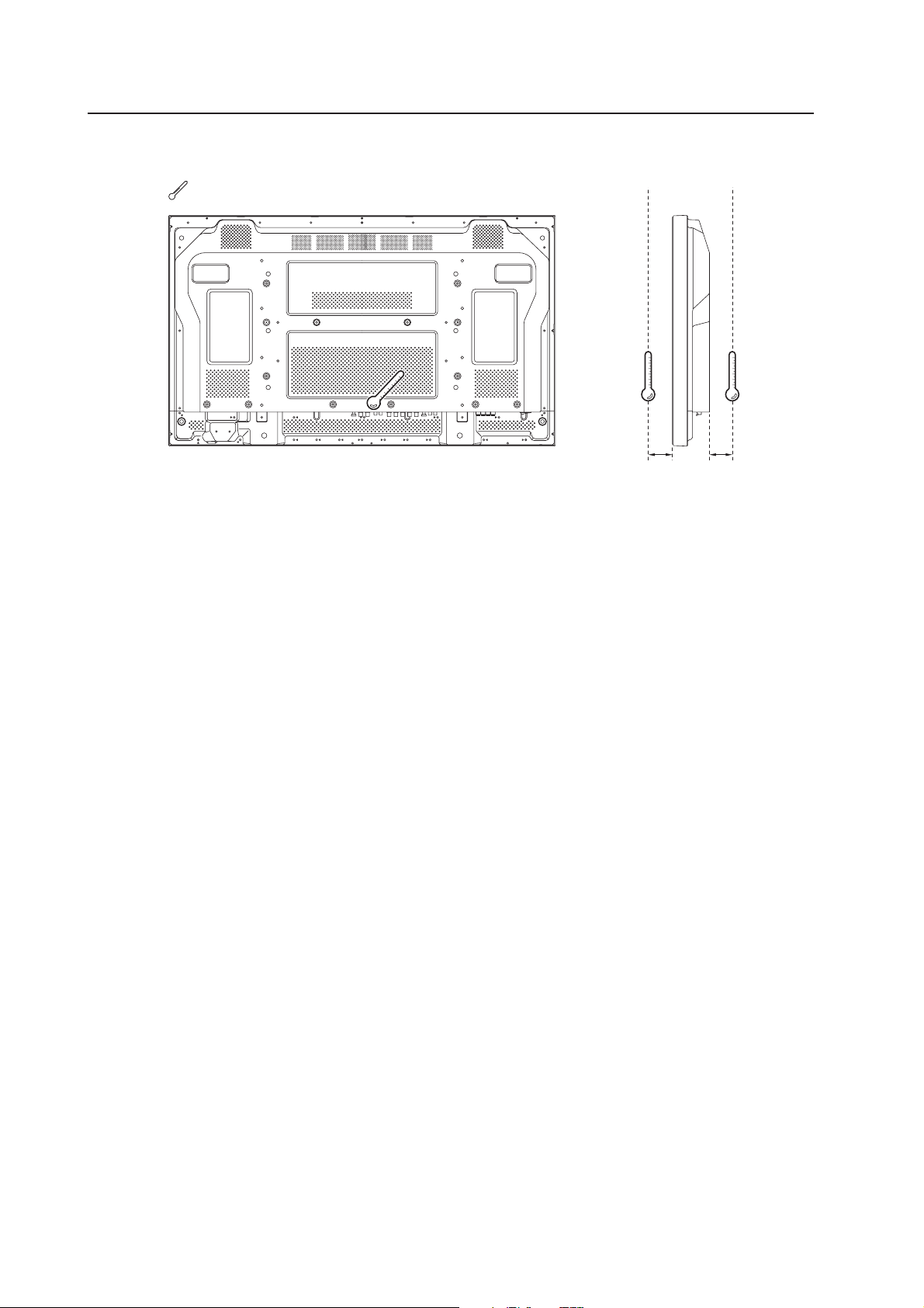
[427CMX]Special Installation (Embedding in the wall)
Temperature Measurement Points (Illustration for reference purposes)
: Thermometer (temperature measurement point)
50 mm 50 mm
• Make measurements at a distance of 50 mm from the unit without directly subjecting the thermometer to fan
exhaust.
• For spaces where temperature fluctuations are likely, gather additional measurement points for adequate data.
60
Page 61

[427CMX]
Special Installation (Embedding in the wall)
(2) Embedding in walls with no space provided behind the unit.
Panting (Punching) net (numerical aperture 50 % or over)
100 mm or
50 mm or
more
more
more
100 mm or
more
100 mm or
100 mm or
more
Cation : Due to possible heat issues, we do not recommend installing the panel in narrow, enclosed areas.
✩ Operating Temperature Restrictions
• Ambient temperature: 0 °C to 40 °C
• The same operating temperature restrictions apply to the speaker system (PDP-S56-LR).
✩ Operating Temperature Restrictions for Upside-Down Installations
* Upside-down mounting is unavailable when embedding this device in a wall.
Methods of Securing: Basic methods of securing are shown below. Avoid blocking or covering areas aside from those
indicated by . The methods indicated by a large “X” must not be used.
Before attaching the unit to fittings, double-check that the thickness and height of the fittings
and the number of bolts is correct.
(Also refer to “3.6.1 Mounting to fittings” (pg. 55).)
Installation is not possible
61
Page 62

[427CMX]Special installation (When the display is put in a box)
3.6.4 When the display is put in a box
Operating this display in confined spaces is not recommended.
• If the display is to be used in a confined space, observe the following conditions shown in the drawing below:
A ≥ 50
B ≥ 50
C ≥ 10
D ≥ 50
Use a mesh with aperture efficiency of 50 % or more.
If hot air remains in the enclosed space, the temperature may rise causing a malfunction or fire. As a precaution, the
inner wall should have sufficient heat resistance or fire resistance.
✩ Usage temperature conditions (BOX air temperature)
• Ambient temperature: 0 °C to 35 °C
: Thermometer
(temperature measurement point)
Exhaust side Intake side
AA
Outside air temperature
measuring point
10 mm
A ≥ 50
B ≥ 50
C ≥ 10
D ≥ 50
BB
10 mm
Rear view (the following area should be made of mesh)
A+
50 mm
A+
50 mm
800 mm or more
800 mm or more
62
CD
Mesh with aperture efficiency
of 50 % or more
A+
50 mm
B+
30 mm
or more
100 mm
or more
100 mm
B+
A+
50 mm
50 mm
Page 63

[427CMX] Special Installation (Ceiling suspension with wires)
3.6.5 Ceiling suspension (with wires)
When suspending with wire, attach the unit either at rows A and B or at rows C and D to keep it from warping. In
addition, the unit must be attached
sides of the vertical and horizontal center lines.
at four or more points, with these points distributed symmetrically on opposite
Attach so that the fan is on the left
side when viewed from the rear.
C
D
C
A
D
B
When suspending from a ceiling with wire, use the brackets shown below to prevent concentrating loads on the upper
two fixing points.
For additional safety, secure the wires to separate fittings or parts of the ceiling.
Use mounting screws of material stronger than soft steel and use hexagonal bolts.
Use wires adequate for the combined weight of the panel and the weight of the support brackets.
No!
When installing the Plasma Display, DO NOT use the handles as means of hanging the display.
Wires
Wires
Screws
Brackets
Brackets
Screws
✩ Operating environment for standard installation
• Ambient Temperature: 0 °C to 40 °C
✩ Operating environment for vertical installation
• Ambient Temperature: 0 °C to 40 °C
✩ Operating temperatures for Upside-Down Installations
(*1, *2)
(*1, *2)
• Ambient Temperature: 0 °C to 40 °
*1
For this installation, set the ‘FAN CONTROL’ to ‘MAX’ as shown in “5.4.3 Adjustment and Setting in the Integrator Mode 14)
Cooling Fan Control Setting” (pg. 235).
*2
When INPUT2 has been selected, use input compatible signal up to 1280x1024 (60 Hz) at ambient temperature condition of 0 °C
to 35 °C.
63
Page 64

[427CMX]Special Installation (Ceiling suspension with wires)
Methods of Securing: Basic methods of securing are shown below. Avoid blocking or covering areas aside from those
indicated by . The methods indicated by a large “X” must not be used.
Before attaching the unit to fittings, double-check that the thickness and height of the fittings,
and the number of bolts is correct.
(Also refer to “3.6.1 Mounting to fittings” (pg. 55).)
Vertical suspension
Attach so that the fan is
on the left side when
viewed from the rear.
Installation is not possible
Installation is not possible
64
Page 65

[427CMX]
Special Installation (Hanging on the wall lengthwise)
3.6.6 Hanging on the wall lengthwise
Carefully read the following imformation before attempting to mount the unit on the wall. Observe the various limitations
specified below.
Be sure to mount the unit so that twisting, bending, or any other deformation does not exceed 4 mm.
Shaded areas indicate attachment points for mounting hardware.
: Thermometer (temperature measurement point)
Attach so that the fan is on the left
side when viewed from the rear.
B
52.552.5
1022
Avoid blocking or
covering this area
on the upper and
lower sides.
21.6
610
10
A
93.4
25
DD
C
10
✩ Operating Temperature Restrictions
Distance from wall (A) BC DAmbient temperature
(*1, *2)
50 mm or more 100 mm or more 50 mm or more 50 mm or more 0 °C to 35 °C
*1
For this installation, set the ‘FAN CONTROL’ to ‘MAX’ as shown in “5.4.3 Adjustment and Setting in the Integrator
Mode 14) Cooling Fan Control Setting” (pg. 235).
*2
When INPUT2 has been selected, use input compatible signal up to 1280x1024 (60 Hz) at ambient temperature
condition of 0 °C to 35 °C.
65
Page 66

[427CMX]Special Installation (Hanging on the wall lengthwise)
Methods of Securing: Basic methods of securing are shown below. Avoid blocking or covering areas aside from those
indicated by . The method indicated by a large “X” must not be used.
Before attaching the unit to fittings, double-check that the thickness and height of the fittings
and the number of bolts is correct.
(Also refer to “3.6.1 Mounting to fittings” (pg. 55).)
Installation is not possible
Note
Heat air is drawn from the interior of the unit by fans. Before installation, consider the heat resistance of the wall or
other surface behind the unit. Exhaust temperatures can be 30 °C higher than the outside temperature.
Note
For wall-mounting, do not bundle the cables in a way that block vents.
Installation is not possible
66
Page 67

[427CMX]
Special Installation (Place product upright and flush, embedded in the wall)
3.6.7 Place product upright and flush into wall (embedding in the wall)
Carefully read the following instructions before trying to embed the unit in a wall. Observe all the limitations specified
below.
Be sure to mount the unit so that twisting, bending, or other deformation of the unit does not exceed 4 mm.
(1) Embedding in walls with space provided behind the unit (with no obstructions within a distance of 300 mm
from the back surface of the unit)
AA
A
X (Front of the unit)
Y (Rear of the unit)
<Viewed from Above>
A
<Viewed from the Right Side>
✩ Operating Temperature Restrictions
Temperature in space X and Y
A: 0 mm to 370 mm 0 °C to 40 °C
*1
For this installation, set the ‘FAN CONTROL’ to ‘MAX’ as shown in “5.4.3 Adjustment and Setting in the Integrator Mode 14)
Cooling Fan Control Setting” (pg. 235).
*2
When INPUT2 has been selected, use input compatible signal up to 1280x1024 (60 Hz) at ambient temperature condition of
0 °C to 35 °C.
(*1, *2)
67
Page 68

Special Installation (Place product upright and flush, embedded in the wall)
[427CMX]
Methods of Securing: Basic methods of securing are shown below. Avoid blocking or covering areas aside from those
indicated by . The methods indicated by a large “X” must not be used.
Before attaching the unit to fittings, double-check that the thickness and height of the fittings
and the number of fixing bolts is correct.
(Also refer to “3.6.1 Mounting to fittings” (pg. 55).)
Attach so that the fan is
on the left side when
viewed from the rear.
Installation is not possible
Installation is not possible
68
Page 69

[427CMX]
Special Installation (Place product upright and flush, embedded in the wall)
(2) Embedding in walls with no space provided behind the unit
Attach so that the
fan is on the left
side when viewed
from the rear.
100 mm or
more
100 mm or
more
more
100 mm or
Panting (Punching) net
(numerical aperture 50 %
or over)
more
100 mm or
50 mm or
more
Cation : Due to possible heat issues, we do not recommend installing the panel in narrow, enclosed areas.
✩ Operating Temperature Restrictions
(*1, *2)
• Ambient temperature: 0 °C to 35 °C
*1
For this installation, set the ‘FAN CONTROL’ to ‘MAX’ as shown in “5.4.3 Adjustment and Setting in the Integrator Mode 14)
Cooling Fan Control Setting” (pg. 235).
*2
When INPUT2 has been selected, use input compatible signal up to 1280x1024 (60 Hz) at ambient temperature condition of 0 °C
to 35 °C.
69
Page 70

Special Installation (Place product upright and flush, embedded in the wall)
[427CMX]
Methods of Securing: Basic methods of securing are shown below. Avoid blocking or covering areas aside from those
indicated by . The methods indicated by a large “X” must not be used.
Before attaching the unit to fittings, double-check that the thickness and height of the fittings
and the number of bolts is correct.
(Also refer to “3.6.1 Mounting to fittings” (pg. 55).)
Attach so that the fan is
on the left side when
viewed from the rear.
Installation is not possible
Installation is not possible
70
Page 71

[427CMX]
Special Installation (Installed facing upward)
3.6.8 Installed facing upward
(1) When installed on top of a horizontal surface <an open space other than a horizontal surface>
Horizontal surface
50 mm or more
Horizontal surface
✩ Operating Temperature Restrictions
(*1)
• Ambient temperature: 0 °C to 35 °C
• The same operating temperature restrictions apply to the speaker system (PDP-S56-LR).
*1
For this installation, set the ‘FAN CONTROL’ to ‘MAX’ as shown in “5.4.3 Adjustment and Setting in the Integrator Mode 14)
Cooling Fan Control Setting” (pg. 235).
Methods of Securing: Basic methods of securing are shown below. Avoid blocking or covering areas aside from those
indicated by . The methods indicated by a large “X” must not be used.
Before attaching the unit to fittings, double-check that the thickness and height of the fittings
and the number of bolts is correct.
(Also refer to “3.6.1 Mounting to fittings” (pg. 55).)
71
Page 72

Special installation (Installed facing upward)
[427CMX]
(2) When the Plasma Display is in a confined space
Operating this display in confined spaces is not recommended.
• If the display is to be used in confined spaces, observe the following conditions shown in the drawing below:
A ≥ 50
• If heat remains in the enclosed space, the temperature may rise causing a malfunction or fire. As a precaution, the
inner wall should have sufficient heat resistance or fire resistance.
• Leave a space at least 10 mm wide when installing glass etc. on the front of the Plasma Display.
✩ Usage temperature conditions
(*1)
• Ambient temperature: 0 °C to 35 °C (Outside air temperature)
• Space enclosed by the back surface of the Plasma Display: 0 °C to 35 °C (Use a fan etc. to discharge air to
maintain this temperature range.)
*1
For this installation, set the ‘FAN CONTROL’ to ‘MAX’ as shown in “5.4.3 Adjustment and Setting in the Integrator Mode 14)
Cooling Fan Control Setting” (pg. 235).
: Thermometer (temperature measurement point)
Outside air temperature
measuring point
Outside air
temperature
measuring point
150 mm
A ≥ 50
Enclosed space air
temperature measuring
point
10 mm
A
50 mm
Enclosed space air temperature
measuring point
Note
When installing the Plasma Display facing upwards, do not place anything on top of it nor apply any load on it from
above.
72
Page 73

[427CMX]
Special installation (Horizontal connections)
3.6.9 Horizontal connections
While the display is designed to accommodate side-by-side installations, keep in mind that specific installation
configurations may affect ventilation. Observe the following requirements:
1 Installation of up to two units (Horizontal connection)
The following table lists the operating temperature conditions when installing more than one panel. Use the units
under conditions that keep the outside atmosphere in this range.
A
Unit A Unit B
✩ Operating Temperature Restrictions
Distance from wall (A) Ambient temperature
50 mm or more 0 °C to 40 °C
2 Installing three or more units (Horizontal connection)
The following table lists the operating temperature conditions. Use the units under conditions that keep the
outside atmosphere in this range.
A
Partition
Unit A Unit B
Unit C
✩ Operating Temperature Restrictions
Distance from wall (A) Ambient temperature
50 mm or more 0 °C to 40 °C
73
Page 74

Special installation (Multiple)
[427CMX]
3.6.10 Multiple
While the display is designed to accommodate side-by-side installations, keep in mind that specific installation
configurations may affect ventilation. Observe the following requirements:
1 Installing multiple (2 Vertical units)
The following table lists the operating temperature conditions when installing more than one panel. Use the units
under conditions that keep the outside atmosphere in this range.
A
Partition
Unit A Unit B Unit C
In case of lateral connections, ensure that left and right partitions are provided.
To prevent heat venting from one video wall plasma panel into another panel, each display must
be oriented in the same direction.
In the above example, each panel is shown with the Pioneer logo at the bottom.
✩ Operating Temperature Restrictions
Distance from wall (A) Ambient temperature
50 mm to 300 mm or less 0 °C to 35 °C
300 mm or more 0 °C to 40 °C
74
Page 75

[427CMX] Special installation
75
Page 76

How to use the standard mounting components
[507CMX : 427CMX]
4.1 Standard Mounting Components Features and Characteristics
In addition to reliability and vivid display resulting from its large screen area, brightness, and image quality, the Plasma
Display (PDP-507CMX/PDP-427CMX) is thin and lightweight. This panel can be mounted in locations not possible for
conventional displays.
We considered various mounting patterns and operating conditions during the design of the Plasma Display (PDP-
507CMX/PDP-427CMX). A wide range of standard mounting hardware is available for easy mounting.
¶ Video Card: PDA-5003/PDA-5004
The video card makes video input and analog RGB input possible.
This product has a total of three lines: a COMPOSITE (1), S INPUT (1), and an analog RGB INPUT or COMPONENT
INPUT (1). Furthermore, it can handle three-line or two-line audio, thus increasing the uses for video presentations.
¶ Table Top Stand: PDK-TS07
This on-board support designed for the Plasma Display enables vertical placement of the unit.
¶ Tilt Mount Unit: PDK-5011
This mount permits tilting of the display downward from the horizontal by up to 25 degrees. Mount depth is 145 mm
or less (in vertical position, without optional speaker). This hardware permits a wide range of viewing angles.
¶ Wall Mount Unit: PDK-WM01
Distance from the rear surface of the Plasma Display to the wall is 32 mm.
This mount provides installation holes for various wall-mounting arrangements. The mount is constructed so that it
can be easily attached to the main unit.
¶ Ceiling Mount Unit: PDK-5012
Simple rod-type mounting hardware permits display panning over a range of 45 degrees and up to 25-degree downward
tilting from the horizontal. This hardware enables installation of the unit in a wide variety of locations.
¶ Mobile Cart: PDK-5014
This is an extremely stable movable stand that one person can use to freely move the Plasma Display.
It can also be used to adjust the screen height and the screen angle to match the line of sight.
¶ PDP Bracket: PDK-5005 (Can be used only with the PDP-507CMX)
Can be used as a handle when moving the unit, or as a frame when wire-suspending it or hanging it on the wall. Most
suitable for temporary use when quick, easy, and safe attachment is necessary.
¶ Speaker System:PDP-S53-LR (Can be used only with the PDP-507CMX)
Speaker System: PDP-S56-LR (Can be used only with the PDP-427CMX)
Two way speakers feature 5 cm (2 in.) tweeter and 8 cm (3-3/16 in.) woofer in a vertical arrangement.
76
Page 77

[507CMX : 427CMX]
Handling the Standard Mounting Components
4.2 Handling the Standard Mounting Components
4.2.1 Handling precautions
This section of the manual discusses ways to mount, install, and handle the mounting hardware exclusively designed
for Pioneer Plasma Displays. Mounting should be performed by qualified experts.
Refer all installation and mounting work to qualified installers, or request assistance from a Pioneer dealer.
4.2.2 Precautions for installation contractors
1) Before installation
Observe the specifications supplied in “3.1 Installation Site Requirements” earlier in this manual.
2) During Installation
Carefully read and observe the contents of this section of the manual.
The installation work should be performed by two or more people.
3) After installation
After installation the mounting hardware, check for adequate strength and properly tightened screws. Repeat this
inspection after mounting the display.
4) Delivering to the customer
(1)Explaining mounting precautions
The mounting contractor is responsible for explaining the following precautions to the customer after mounting
and installation work is complete. Even if the particulars of an installation are letter-perfect, your work may be
perceived as inadequate unless you patiently and thoroughly explain these precautions to the customer.
¶ The following are highly dangerous and must be avoided at all times:
• Any sudden application of force, including pushing and pulling
• Splashing water on the unit
• Placing any object on the unit
• Touching mount screws and other mounting hardware
¶ For worry-free use of the unit:
• If problem arises, the user should immediately ask the installation contractor to inspect the unit and make
repairs if necessary.
• To guard against accidents, ask the customer avoid making tilt or height adjustments. Changes should be
referred to the installation contractor.
(2)Mounting contractor contact form
As the mounting and installation contractor, please complete the contractor contact form supplied with the unit
and give it to the end-user after post-installation inspections are complete.
(3)Periodic inspections
Over time, aging of various components of the suspension/mounting hardware that may not be readily visible can
render the installation unreliable. This may lead to the display breaking free of its mounting. Please recommend
periodic inspections.
77
Page 78

Installation of the Attachment Stand
[427CMX]
4.3 Installation of the Attachment Stand
(Can be used only with the PDP-427CMX)
Be sure to fix the supplied stands to the installation surface.
Use commercially available M8 bolts that are 25 mm
longer than the thickness of the installation surface.
1 Fix the supplied stands to the installation surface at
each of the 4 prepared holes using commercially
available M8 bolts.
Front
517 mm
(Bolt hole thread pitch)
Rear
110 mm
Always install the supplied display stands
according to the dimensions shown in
the accompanying illustration.
3 Tighten the bolt against the washer so as to secure
the unit.
After manually tightening the bolts, completely tighten
them with the attached tools.
Use a 6 mm hexagonal
wrench to tighten the bolt.
The unit weights 30 kg. or more.
Its thinness makes it unstable. Therefore,
CAUTION
it should be unpacked, carried, and
installed by two or more people.
2 Insert the unit into the stand.
78
Page 79

[427CMX]
Dimensions
(Unit: mm)
633
610
Installation of the Attachment Stand
31.4
252.4
40.4
74.398
300
127.7
53.5
23
447.2 70
1022
300
110
66.8
70
ø
24
10
R12
22.1
79
10
12
50
24.3
10
79
Page 80

Video Card: PDA-5003/PDA-5004
4.4 Video Card: PDA-5003/PDA-5004
4.4.1 Specifications
External dimensions ................. PDA-5003: 301.5 mm (W) × 27.6 mm (H) × 148.9 mm (D)
(11-7/8 in. (W) × 1-3/32 in. (H) × 5-7/8 in. (D))
PDA-5004: 301.5 mm (W) × 27.6 mm (H) × 148.3 mm (D)
(11-7/8 in. (W) × 1-3/32 in. (H) × 5-27/32 in. (D))
Weight ....................................... 0.4 kg (14 oz)
Dimensions of packaging......... 359 mm (W) × 68 mm (H) × 234 mm (D)
(14-1/8 in. (W) × 2-11/16 in. (H) × 9-7/32 in. (D))
Package weight......................... 1.4 kg (3.1 lbs.)
Input/Output jacks
7 PDA-5003
Video-related
INPUT1 Input The following signal is supported only when a PDA-5003 is installed.
• Component video signal
Y ........................ 1 Vp-p/75 Ω/negative sync.
PB/CB, PR/CR........ 0.7 Vp-p (color 100 %)/75 Ω
[507CMX : 427CMX]
INPUT2 Input DVI-D 24-pin connector
Digital video signal (HDCP supported)
INPUT3 Input S-VIDEO jack (Mini-DIN, 4-pin connector)
• Y/C separate video signal
Y ........................ 1 Vp-p/75 Ω/negative sync.
C ........................ 0.286 Vp-p/75 Ω (NTSC)
0.3 Vp-p/75 Ω (PAL)
INPUT4 Input BNC jack
• Composite video signal ........ 1 Vp-p/75 Ω/negative sync.
Output BNC jack .................................. 75 Ω/with buffer
INPUT5 Input BNC jack × 5
• RGB signal (for SYNC ON G)
RGB ........................... 0.7 Vp-p/75 Ω/no sync.
HD/VS, VD ................. TTL level/positive and negative polarity/75 Ω or 2.2 kΩ
(with impedance switching)
SYNC ON G ............... 1 Vp-p/75 Ω/negative sync.
• Component video signal
Y ................................ 1 Vp-p/75 Ω/negative sync.
, PR/CR................ 0.7 Vp-p (color 100 %)/75 Ω
P
B/CB
Audio-related
Input AUDIO INPUT (for INPUT3/4)
Pin jack (×2)
L/R ............ 500 mVrms/more than 10 kΩ
AUDIO INPUT (for INPUT5)
Pin jack (×2)
L/R ............ 500 mVrms/more than 10 kΩ
80
Page 81

[507CMX : 427CMX]
7 PDA-5004
Video-related
INPUT1 Input The following signal is supported only when a PDA-5004 is installed.
• Component video signal
Y ........................ 1 Vp-p/75 Ω/negative sync.
PB/CB, PR/CR........ 0.7 Vp-p (color 100 %)/75 Ω
INPUT2 Input DVI-D 24-pin connector
Digital video signal (HDCP supported)
INPUT3 Input S-VIDEO jack (Mini-DIN, 4-pin connector)
• Y/C separate video signal
Y ........................ 1 Vp-p/75 Ω/negative sync.
C ........................ 0.286 Vp-p/75 Ω (NTSC)
0.3 Vp-p/75 Ω (PAL)
INPUT4 Input RCA jack
• Composite video signal ........ 1 Vp-p/75 Ω/negative sync.
Output RCA jack .................................. 75 Ω/with buffer
INPUT5 Input RCA jack
• RGB ................... 0.7 Vp-p/75Ω/no sync.
SYNC ON G ....... 1 Vp-p/75 Ω/negative sync.
• Component video signal
Y ........................ 1 Vp-p/75 Ω/negative sync.
B/CB, PR/CR ........ 0.7 Vp-p (color 100 %)/75 Ω
P
Video Card: PDA-5003/PDA-5004
Audio-related
Input AUDIO INPUT (for INPUT3)
Pin jack (×2)
L/R ............ 500 mVrms/more than 10 kΩ
AUDIO INPUT (for INPUT4)
Pin jack (×2)
L/R ............ 500 mVrms/more than 10 kΩ
AUDIO INPUT (for INPUT5)
Pin jack (×2)
L/R ............ 500 mVrms/more than 10 kΩ
Accessories
Label for remote control unit ............................... × 1
Connector indicator label ..................................... × 1
Screws (3 × 8) ..................................................... × 2
Operating instructions ......................................... × 1
Warranty .............................................................. × 1
81
Page 82

Video Card: PDA-5003/PDA-5004
4.4.2 External Dimensions
(Unit: mm)
7 PDA-5003
[507CMX : 427CMX]
262
137.3
7 PDA-5004
148.9
301.5
27.6
262
82
137.3
148.3
301.5
27.6
Page 83

[507CMX : 427CMX]
<PDP-507CMX connection panel: when equipped with PDA-5003>
(112.5) 123.6 17 44.5 107.5 1212 28 38 42 33 37
★: Symbol indicates the alignment point.
<PDP-507CMX connection panel: when equipped with PDA-5004>
(112.5) 123.6 17 44.5 107.5 1212 28 38 42 33 39
Video Card: PDA-5003/PDA-5004
(180.3)95141.61436.518181818221421.51837
39 14 26 14 26 14 141426 34 14 141.6 95 (180.3)
★: Symbol indicates the alignment point.
<PDP-427CMX connection panel: when equipped with PDA-5003>
(121) 17 44.5 122.6 12 12 28 38 42 33 37
37 18 21.5 14 22 18 18 18 18 36.5 14 132.6 62.5 43 (78.8)
★: Symbol indicates the alignment point.
<PDP-427CMX connection panel: when equipped with PDA-5004>
(121) 17 44.5 122.6 12 12 28 38 42
33 39
39 14 26 14 26 14 26 14 14 34 14 132.6 62.5 43 (78.8)
★: Symbol indicates the alignment point.
83
Page 84

Video Card: PDA-5003/PDA-5004
4.4.3 Installing procedures
Installation instructions are listed below. When installing
the unit, if a screw or other object should drop inside the
Plasma Display, immediately consult your nearest Pioneer
Service Center. Continuing operation may damage the
panel. This device has been designed for installation on
the Pioneer Plasma Display PDP-507CMX/PDP-427CMX.
Installation procedures are as follows:
Check the following before installing this video card:
• Plasma Display is disconnected from the computer and
any other devices.
• The Plasma Display is unplugged from the wall outlet
before installing/removing a card from a panel slot.
[507CMX : 427CMX]
Installation
Illustration depicts PDA-5003 model
1 Remove the protective cover over the video card
slot on the Plasma Display’s terminal panel.
Protective cover
Installation Notes:
• Do not install the PDA-5002 on the PDP-507CMX/PDP-
427CMX display units.
• When opening the protective cover, take care not to
drop screws or other objects in the opening. Objects
dropped inside the display may cause damage or
malfunction.
• When installing a video card, if the Plasma Display is
laid with its screen side facing down, the work surface
should be flat and level. The packing material, a blanket,
or other soft material should be spread on the work
surface to protect the screen before laying the panel
down. Take care to prevent scratches or other damage
to the unit from tools or other objects. Never rest the
display on a surface in such a way that weight or
pressure is placed only on the screen surface.
• This video card has been designed for exclusive use with
the Pioneer Plasma Display PDP-507CMX/PDP-427CMX.
Do not attempt unauthorized modifications or alterations
since malfunction or damage may result.
• Take care not to modify or damage the card’s internal
devices in any way.
• Before installation, take precautions to eliminate static
electricity on your body. Do not touch the card’s circuitry
or devices.
• This device has not been designed to be repeatedly
removed and reinstalled. Avoid removing the card once
it is installed.
• When installing the PDA-5003, it may be necessary to
adjust the impedance selector switch setting. Confirm
this item before installing.
• Prior to insertion, use a cloth containing ethanol to clean
the PCI bus. Wipe in the direction of the electrodes to
remove dirt and dust. Wiping with a dry cloth may cause
damage due to static electricity.
2 Align the video card with the two rails visible inside
of the port then gently and evenly insert the card.
rails
Note
• Be very careful when inserting the card. Aim the card’s
mounting surface oriented toward the rear of the Plasma
Display. The card or display may be damaged if the card
is inserted crookedly or with excessive force.
• Impedance selector switch is found only on the PDA-
5003.
Device
mounting
surface
Impedance
selector switch
75 Ω 2.2 kΩ
VIDEO
S-VIDEO INPUT3
INPUT 3/4
INPUT4
AUDIO
ANALOG RGB
HD (H/V SYNC)
AUDIO
INPUT5
3 After inserting the video card all the way into the
slot, confirm that it is seated securely. The screws
removed in step 1 to secure the card in place.
VIDEO
S-VIDEO INPUT3
INPUT 3/4
INPUT4
ANALOG RGB
AUDIO
HD (H/V SYNC)
AUDIO
INPUT5
84
Page 85

[507CMX : 427CMX]
4 Affix the accessory connector indicator label to the
Plasma Display then affix the remote control label
to the remote control that is furnished with the
Plasma Display.
VIDEO
S-VIDEO INPUT3
INPUT3
S-VIDEO
PDA-5003
PDA-5004
INPUT 3/4
INPUT4
INPUT4 INPUT5AUDIO
VIDEO INPUT3
IN OUT R L RLGBRHDVD
RGB (BNC)
ANALOG RGB
AUDIO
/
4 ANALOG RGB AUDIO
(ON SYNC) (H/V SYNC)
COMPONENT
Notes
Note
Use a soft cloth to gently wipe away any dust or soiling
from the surface before affixing the label.
Video Card Removal (Be careful not to insert
and remove it frequently).
AUDIO
INPUT5
HD (H/V SYNC)
Video Card: PDA-5003/PDA-5004
1 Remove the two screws holding the video card.
VIDEO
S-VIDEO INPUT3
INPUT 3/4
INPUT4
ANALOG RGB
AUDIO
HD (H/V SYNC)
AUDIO
INPUT5
2 Holding the inside tabs, pull the video card straight
out.
Impedance
S-VIDEO INPUT3
Device
mounting
surface
VIDEO
INPUT4
INPUT 3/4
75 Ω
AUDIO
selector switch
2.2 kΩ
ANALOG RGB
HD (H/V SYNC)
INPUT5
AUDIO
85
Page 86

Video Card: PDA-5003/PDA-5004
[507CMX : 427CMX]
4.4.4 Input connectors on the Plasma Display
with video card
7 When using PDA-5003
Consult the following chart when making connections to
a Plasma Display equipped with this video card.
Input
Connected
component
and signals
AV component
Personal computer
(PC)
*1 Although INPUT1 and INPUT5 are compatible with various
*2 INPUT1 is compatible with Microsoft’s Plug & Play (VESA
*3 Depending on the video output board of the computer, this
*4 INPUT2 is compatible with Microsoft’s Plug & Play (VESA
Connector
Analog RGB
Component video
S video
Composite video
Digital RGB
Analog RGB
S video
Composite video
Digital RGB
kinds of signals, setup using the on-screen menu is
necessary after connections are made in order match the
characteristics of the source component.
DDC 1/2B).
type of connection may not be possible.
DDC 2B).
INPUT
*1
1
*2
INPUT
2
*4
INPUT
3
*3
INPUT
4
*3
INPUT
*1
5
7 When using PDA-5004
Consult the following chart when making connections to
a Plasma Display equipped with this video card.
Input
Connected
component
and signals
AV component
Personal computer
*1 Although INPUT1 and INPUT5 are compatible with various
*2 INPUT1 is compatible with Microsoft’s Plug & Play (VESA
*3 Depending on the video output board of the computer, this
*4 INPUT2 is compatible with Microsoft’s Plug & Play (VESA
Connector
Analog RGB
Component video
S video
Composite video
Digital RGB
Analog RGB
S video
Composite video
Digital RGB
kinds of signals, setup using the on-screen menu is
necessary after connections are made in order match the
characteristics of the source component.
DDC 1/2B).
type of connection may not be possible.
DDC 2B).
(PC)
INPUT
*1
1
*2
INPUT
2
*4
INPUT
3
*3
INPUT
4
*3
INPUT
*1
5
86
4.4.5 Connection to INPUT1 and INPUT5
7 When using PDA-5003
Various components can be connected to the INPUT1 and
INPUT5 jacks. After connections are made, on-screen
setup is necessary to match the characteristics of the
connected component.
INPUT5
Output source
Video component/
personal
computer (PC)
with RGB output
Video component
with component
video output
: Do not connect anything. : Connect to this jack.
Note
Components compatible with INPUT1 are also compatible with
INPUT5. When making connections to INPUT1, please refer to
the Plasma Display’s Operating Instructions.
7 When using PDA-5004
Various components can be connected to the INPUT1 and
INPUT5 jack. After connections are made, on-screen setup
is necessary to match the characteristics of the connected
component.
Output source
Video component/personal
computer (PC) with RGB
output
Video component with
component video output
: Connect to this jack.
Note
When making connections to INPUT1, please refer to the
Plasma Display’s Operating Instructions.
jack
G ON SYNC
INPUT5 jack
[ON SYNC]
GBR
R
B
RG
B
GBR
Y PB/CB PR/CR
Y
G ON SYNC
Y
[H/V SYNC]
HD VD
H/V SYNC
HD
PB/CB
B
PB/CB
VD
PR/CR
R
PR/CR
Page 87

[507CMX : 427CMX]
4.4.6 Connection to INPUT1 or INPUT5
7 When using PDA-5003
Video Card: PDA-5003/PDA-5004
7 When using PDA-5004
Connection to AV components
Connection to AV component equipped with
component video jacks
Make component video connections for AV
components equipped with component video jacks.
When connecting to ANALOG RGB IN (INPUT1)
ANALOG RGB OUT
(D-Sub)
On-screen setup is necessary after connection.
When connecting to ANALOG RGB (INPUT5)
INPUT1
ANALOG RGB IN
(D-Sub)
Connection to AV components
Connection to AV component equipped with
component video jacks
Make component video connections for AV
components equipped with component video jacks.
When connecting to ANALOG RGB IN (INPUT1)
ANALOG RGB OUT
(D-Sub)
On-screen setup is necessary after connection.
When connecting to COMPONENT VIDEO (INPUT5)
INPUT1
ANALOG RGB IN
(D-Sub)
ANALOG RGB
BR VDHD (H/V SYNC)G(ON SYNC)
INPUT5
Connect the Y signal to the G jack, the PB/CB signal to
the B jack, and the P
R/CR signal to the R jack.
On-screen setup is necessary after connection.
INPUT5 jacks are all BNC jacks.
If necessary, use commercially available BNC/pin-plug
conversion adapters to make connections.
Note
The Plasma Display and this Video Card are designed to
support component video signals with standard, stable signal
levels and sync signals. As a result, some image disruption
may be generated during use of various special trick play
functions on video components.
COMPONENT
VIDEO
Y Pb/Cb Pr/Cr
INPUT5
Connect the Y signal to the Y jack, the PB/CB signal to
the P
B/CB jack, and the PR/CR signal to the PR/CR jack.
Note
The Plasma Display and this Video Card are designed to
support component video signals with standard, stable signal
levels and sync signals. As a result, some image disruption
may be generated during use of various special trick play
functions on video components.
87
Page 88

Video Card: PDA-5003/PDA-5004
Connection of G ON SYNC analog RGB source
Make G ON SYNC connections for a component with
output that has the synchronization signal layered on
top of the green signal.
[507CMX : 427CMX]
When connecting to ANALOG RGB IN (INPUT1)
ANALOG RGB OUT
(D-Sub)
INPUT1
ANALOG RGB IN
(D-Sub)
On-screen setup is necessary after connection.
When connecting to ANALOG RGB (INPUT5)
[Connections for PDA-5003]
ANALOG RGB
INPUT5
When connecting to COMPONENT VIDEO (INPUT5)
[Connections for PDA-5004]
COMPONENT
VIDEO
Y Pb/Cb Pr/Cr
INPUT5
Connect the G ON SYNC signal to the Y jack, the B
signal to the P
B/CB jack, and the R signal to the PR/CR
jack.
On-screen setup is necessary after connection.
BR VDHD (H/V SYNC)G(ON SYNC)
On-screen setup is necessary after connection.
Note
When making G ON SYNC connections, do not make any
connections to the VD or HD jacks. If connections are made,
the picture may be not displayed normally.
88
Page 89

[507CMX : 427CMX]
Video Card: PDA-5003/PDA-5004
Connection of composite SYNC analog RGB
source
Make composite SYNC connections for a component
with output that has the vertical synchronization signal
layered on top of the horizontal synchronization signal.
When connecting to ANALOG RGB IN (INPUT1)
ANALOG RGB OUT
(D-Sub)
On-screen setup is necessary after connection.
When connecting to ANALOG RGB (INPUT5)
[Connections for PDA-5003]
INPUT1
ANALOG RGB IN
(D-Sub)
Connection to a personal
computer
Connection method differs depending on the computer
type. When connecting, please thoroughly read the
computer’s operating instructions.
Before making connections, be sure to make sure that
the personal computer’s power and display’s main
power is off.
For the PC input signals and screen sizes that the
display is compatible with, please refer to the Plasma
Display’s Operating Instructions.
Connection of separate SYNC analog RGB
source
Make separate SYNC connections for a personal
computer that has RGB output separated into 5 output
signals: green, blue, red, horizontal synchronization
signal, and vertical synchronization signal.
When connecting to ANALOG RGB (INPUT5)
[Connections for PDA-5003]
ANALOG RGB
BR VD
G(ON SYNC)
HD (H/V SYNC)
INPUT5
INPUT5
BR VD
G(ON SYNC)
ANALOG RGB
HD (H/V SYNC)
When using INPUT5, set the impedance selector
switch to match the output impedance of the
connected component’s synchronization signal.
When the output impedance of the sync signal is below
75 Ω remove the video card and set the impedance
selector switch to 75 Ω.
On-screen setup is necessary after connection.
Note
When making composite SYNC connections, do not connect
anything to the VD jack. If connected to, the picture may not
be displayed properly.
When using INPUT5, set the impedance selector
switch to match the output impedance of the
connected computer’s synchronization signal.
When the output impedance of the sync signal is below
75 Ω remove the video card and set the impedance
selector switch to 75 Ω.
On-screen setup is necessary after connection.
89
Page 90

Video Card: PDA-5003/PDA-5004
[507CMX : 427CMX]
When connecting to ANALOG RGB IN (INPUT1)
ANALOG RGB OUT
(D-Sub)
INPUT1
ANALOG RGB IN
(D-Sub)
Connect the cable corresponding to the shape of the
input terminal on the display and the personal
computer’s output terminal.
Secure by tightening the terminal screws on both units.
On-screen setup is necessary after connection.
Note
Depending on the type of computer model being connected, a
conversion connector or adapter etc. provided with the
computer or sold separately may be necessary.
For details, please read your PC’s instruction manual or consult
the maker or nearest dealer of your computer.
When connecting to ANALOG RGB OUT (INPUT1)
Connection of G ON SYNC analog RGB source
Make G ON SYNC connections for a personal computer
with output that has the synchronization signal layered
on top of the green signal.
When connecting to ANALOG RGB IN (INPUT1)
ANALOG RGB OUT
(D-Sub)
On-screen setup is necessary after connection.
When connecting to ANALOG RGB (INPUT5)
[Connections for PDA-5003]
G(ON SYNC)
INPUT1
ANALOG RGB IN
(D-Sub)
ANALOG RGB
BR VD
HD (H/V SYNC)
INPUT5
ANALOG RGB OUT
(D-Sub)
INPUT1
ANALOG RGB IN
(D-Sub)
To an external monitor
With the Plasma Display, it is possible to output the
video signal to an external monitor or other component
from the ANALOG RGB OUT (INPUT1) terminal.
Note
A video signal will not be output from the ANALOG RGB OUT
(INPUT1) terminal when the main power of this unit is off or in
standby.
On-screen setup is necessary after connection.
Note
When making G ON SYNC connections, do not make any
connections to the VD or HD jacks. If connections are made,
the picture may be not displayed normally.
90
Page 91

[507CMX : 427CMX]
Video Card: PDA-5003/PDA-5004
When connecting to COMPONENT VIDEO (INPUT5)
[Connections for PDA-5004]
COMPONENT
VIDEO
Y Pb/Cb Pr/Cr
INPUT5
On-screen setup is necessary after connection.
Connection of composite SYNC analog RGB
source
Make composite SYNC connections for a personal
computer with output that has the vertical
synchronization signal layered on top of the horizontal
synchronization signal.
When connecting to ANALOG RGB IN (INPUT1)
ANALOG RGB OUT
(D-Sub)
INPUT1
ANALOG RGB IN
(D-Sub)
When connecting to ANALOG RGB (INPUT5)
[Connections for PDA-5003]
INPUT5
BR VD
G(ON SYNC)
ANALOG RGB
HD (H/V SYNC)
When using INPUT5, set the impedance selector
switch to match the output impedance of the
connected computer’s synchronization signal.
When the output impedance of the sync signal is below
75 Ω remove the video card and set the impedance
selector switch to 75 Ω.
On-screen setup is necessary after connection.
Notes
÷ When making composite SYNC connections, do not connect
anything to the VD jack. If connected to, the picture may not
be displayed properly.
÷ Some types of computer devices manufactured by Apple
Computer, Inc. are equipped with both G ON SYNC and
composite SYNC outputs. This type of component should
be connected using the G ON SYNC connection.
On-screen setup is necessary after connection.
91
Page 92

Video Card: PDA-5003/PDA-5004
[507CMX : 427CMX]
4.4.7 Connection to INPUT2
A computer equipped with DVI output (digital RGB signal)
or an AV component equipped with DVI output, can be
connected to the Plasma Display’s DVI connector.
INPUT2
DIGITAL RGB
(DVI-D)
Computer or AV component
On-screen setup is necessary after connection.
Note
Use a DVI-D 24-pin (digital only) cable for the connection.
NOTICE
¶ INPUT2 is compatible with Microsoft’s Plug & Play (VESA
DDC 2B).
¶ For screen sizes and input signals compatible with INPUT2,
please refer to the Plasma Display’s Operation Instructions.
4.4.9 Connection to INPUT4
Connect an AV component that has a video output jack
to the video card’s INPUT4 jack. The VIDEO OUT
(INPUT4) jack can be used to output the video signal to
a separate monitor, recording device or other
component with video input capability.
Note
A video signal will not be output from the VIDEO OUT
(INPUT4) jack when the main power of this display is off or in
standby mode.
[When using PDA-5003]
INPUT4
VIDEO
OUT
IN
To a monitor or a
recording device
AV component
[When using PDA-5004]
VIDEO
INPUT4
4.4.8 Connection to INPUT3
Connect an AV component that has S-video output jack
to the video card’s S-VIDEO (INPUT3) jack.
INPUT3
S-VIDEO
AV component
IN OUT
To a monitor or a
recording device
AV component
Signals to the INPUT3 and INPUT4 jacks are all
compatible with the following TV systems: NTSC,
PAL, SECAM, 4.43NTSC, PAL M and PAL N.
92
Page 93

[507CMX : 427CMX]
4.4.10 About DTV set top box connection
To ensure proper connection, please carefully read the
instruction manual supplied with the DTV set top box.
The set top box output signals that this display is
compatible with are as follows.
Video Card: PDA-5003/PDA-5004
Video
signal type
HDTV
SDTV
Video signal
1125i (1080i)
750p (720p)
525i (480i)
625i (575i)
525p (480p)
625p (575p)
Video
signal format
Component
RGB
Composite
S Video
Component
RGB
Component
RGB
Jacks where connection is possible
INPUT1
INPUT3INPUT2
INPUT5INPUT4
93
Page 94

Video Card: PDA-5003/PDA-5004
4.4.11 Audio connections
Before making connections, be sure to check that the
audio component’s power and the display’s main power
is off.
Connect an audio component to the audio
input jack of the Plasma Display with installed
video card.
When the video card is installed, the Plasma Display
provides four or five audio input jacks and one audio
output jack. Consult the following chart to choose the
proper audio input for each video input.
[507CMX : 427CMX]
Audio connections for component connected to
INPUT2
INPUT1
OUTPUT INPUT2
AUDIO
AUDIO AUDIO
Video
input
INPUT1
INPUT2
INPUT5
INPUT3
INPUT4
*1
When using the PDA-5003, the INPUT3 and INPUT4
Audio input Sound output
Stereo mini jack (L/R)
Stereo mini jack (L/R)
Pin jacks (L/R)
Pin jacks (L/R)
Pin jacks (L/R)
Sound of the selected
video input is output from
the
*1
• SPEAKER (L/R) terminals
*1
• Stereo mini jack (L/R).
audio input connectors are shared.
Audio connection for component connected to
INPUT1
INPUT1
OUTPUT INPUT2
AUDIO
AUDIO AUDIO
A stereo miniplug cable can be used to connect the
audio output from the component connected to
INPUT2, to the Plasma Display’s AUDIO (INPUT2) jack
(L/R).
Sound is output from both the AUDIO (OUTPUT) stereo
mini jack (L/R) and the SPEAKER (L/R) terminals
according to the video input selection.
Audio connection for component connected to
INPUT5
INPUT5
AUDIO
RL
A stereo miniplug cable can be used to connect the
audio output from the component connected to
INPUT1, to the Plasma Display’s AUDIO (INPUT1) jack
(L/R).
Sound is output from both the AUDIO (OUTPUT) stereo
mini jack (L/R) and the SPEAKER (L/R) terminals
according to the video input selection.
94
The audio line for the component connected to INPUT5
can be connected to the AUDIO R/L (INPUT5) pin jacks.
Sound is output from both the AUDIO (OUTPUT) stereo
mini jack (L/R) and the SPEAKER (L/R) terminals
according to the video input selection.
Page 95

[507CMX : 427CMX]
Video Card: PDA-5003/PDA-5004
[When using PDA-5003]
Audio connection for component connected to
INPUT3 or INPUT4
AUDIO
INPUT 3/4
RL
Audio input to the AUDIO R/L (INPUT3/4) pin jacks is
possible for a component connected to either INPUT3
or INPUT4.
Sound is output from both the AUDIO (OUTPUT) stereo
mini jack (L/R) and the SPEAKER (L/R) terminals
according to the video input selection.
[When using PDA-5004]
Audio connection for component connected to
INPUT3
INPUT3
AUDIO
RL
The audio line for the component connected to INPUT3
can be connected to the AUDIO R/L (INPUT3) pin jacks.
Sound is output from both the AUDIO (OUTPUT) stereo
mini jack (L/R) and the SPEAKER (L/R) terminals
according to the video input selection.
Audio connection for component connected to
INPUT4
INPUT4
AUDIO
RL
The audio line for the component connected to INPUT4
can be connected to the AUDIO R/L (INPUT4) pin jacks.
Sound is output from both the AUDIO (OUTPUT) stereo
mini jack (L/R) and the SPEAKER (L/R) terminals
according to the video input selection.
95
Page 96

Video Card: PDA-5003/PDA-5004
[507CMX : 427CMX]
INPUT Response Signals
INPUT 1, 5
7 Video signals supported ★ (applies only when
equipped with PDA-5003/PDA-5004)
50
60
Horizontal
Frequency
Fh (kHz)
15.625
28.13
31.25
37.50
56.20
62.50
15.734
31.5
33.75
45.0
67.5
Signal Format
Component
RGB
Component
RGB
Component
RGB
Component
RGB
Component
RGB
Component
RGB
Component
RGB
Component
RGB
Component
RGB
Component
RGB
Component
RGB
Remark
625i(576i)/SDTV
1125i(1080i)/HDTV
625p(576p)/SDTV
750p(720p)/HDTV
1125p(1080p)/HDTV
520i(480i)/SDTV
525i(480i)/SDTV
525p(480p)/SDTV
1125i(1080i)/HDTV
1125i(1035i)/HDTV
750p(720p)/HDTV
1125p(1080p)/HDTV
Vertical
Frequency
Fv (Hz)
7 PC signals supported
Resolution
(Dot x Line)
640x400 70.1 Hz 31.5 kHz NEC PC-9800
720x400 70.1 Hz 31.5 kHz NEC PC-9800
640x480 59.9 Hz 31.5 kHz
848x480 60 Hz 31.0 kH z
852x480 60 Hz 31.7 kH z
800x600 56.3 Hz 35.2 kHz
832x624 74.6 Hz 49.7 kHz Apple Macintosh 16”
1024x768 60 Hz 48.4 kH z
1280x768 56.2 Hz 45.1 kH z
1360x765
1360x768
1376x768 59.9 Hz 48.3 kHz I/O DATA
1280x800 59.8 Hz 49.7 kHz CVT
1280x854 60 Hz 53.1 kHz
1152x864 60 Hz 53.7 kH z
1152x870 75.1 Hz 68.7 kHz Apple Macintosh 21”
1152x900 66 Hz 61.8 kHz Sun Microsystems LO
1440x900 59.9 Hz 55.9 kHz Apple Macintosh 17”
1280x960 60 Hz 60.0 kH z
1280x1024 60 Hz 63.9 kHz Work station (SGI)
1400x1050 60 Hz 65.3 kH z
1680x1050 60 Hz 65.3 kH z
1600x1200 60 Hz 75.0 kH z
1920x1200 59.9 Hz 74.6 kHz CVT
1920x1200RB 60 Hz 74.0 kHz CVT
Refresh rate
Vertical
85.1 Hz 37.9 kHz
66.7 Hz 35.0 kHz Apple Macintosh 13”
72.8 Hz 37.9 kHz
75 Hz 37.5 kHz
85 Hz 43.3 kHz
100.4 Hz 51.1 kHz I/O DATA
120.4 Hz 61.3 kHz I/O DATA
60.3 Hz 37.9 kHz
72.2 Hz 48.1 kHz
75 Hz 46.9 kHz
85.1 Hz 53.7 kHz
99.8 Hz 63.0 kHz I/O DATA
120 Hz 75.7 kHz I/O DATA
60 Hz 49.7 kHz Work station (SGI)
70.1 Hz 56.5 kHz
75 Hz
(74.9 Hz )
85 Hz 68.7 kHz
100.6 Hz 80.5 kHz I/O DATA
119.4 Hz 95.5 kHz
59.8 Hz 48 kHz
69.8 Hz 56 kHz
60 Hz
60 Hz
72 Hz 64.9 kHz
75 Hz 67.5 kHz
76 Hz 71.7 kHz Sun Microsystems HI
85 Hz 85.9 kHz
60 Hz 64.0 kHz
60 Hz 64.6 kHz
71.2 Hz 75.1 kHz
72 Hz 78.1 kHz Work station (HP)
75 Hz 80.0 kHz
76.1 Hz 81.1 kHz Work station (SUN)
85 Hz 91.1 kHz
100.1 Hz 108.5 kHz I/O DATA
74.9 Hz 82.3 kHz
85 Hz 93.9 kHz
65 Hz 81.3 kHz
70 Hz 87.5 kHz
75 Hz 93.8 kHz
85 Hz 106.3 kH z
Horizontal
60.0 kHz
(60.2 kHz)
47.7 kHz
47.7 kHz
Remark
( ) indicates Apple
Macintosh 19
I/O DATA
PC
Work station (EWS4800)
Work station (EWS4800)
96
Page 97

[507CMX : 427CMX]
INPUT 2
7 Video signals supported ★ (applies only when
equipped with PDA-5003/PDA-5004)
Vertical
Frequency
Fv (Hz)
The following signals are not formally supported, but can
be displayed (They are not recorded in EDID data).
Vertical
Frequency
Fv (Hz)
50
* They may not be displayed normally depending on the
connected device.
Horizontal
Frequency
Fh (kHz)
50
60
60
50
28.13
31.25
37.50
31.5
33.75
45.0
Horizontal
Frequency
Fh (kHz)
15.6
56.25
15.8
31.5
67.5
62.5
Signal
Format
RGB
RGB
RGB
RGB
RGB
RGB
Signal
Format
RGB
RGB
RGB
RGB
RGB
RGB
Remark
1125i(1080i)/HDTV
625p(576p)x720 dot/SDTV
750p(720p)/HDTV
525p(480p)x720 dot/SDTV
1125i(1080i)/HDTV
750p(720p)/HDTV
Remark
625i(576i)/SDTV
1125p(1080p)/HDTV
525i(480i)/SDTV
525p(480p)x640 dot/SDTV
1125p(1080p)/HDTV
1250p/HDTV
Video Card: PDA-5003/PDA-5004
7 PC signals supported
Resolution
(Dot x Line)
640x480 59.9 Hz 31.5 kHz
720x400 70.1 Hz 31.5 kHz NEC PC-9800
848x480 60 Hz 31.0 kH z
852x480 60 Hz 31.7 kH z
800x600 56.3 Hz 35.2 kHz
1024x768 60 Hz 48.4 kH z
1280x768 56.2 Hz 45.1 kH z
1280x800 59.8 Hz 49.7 kH z
1280x854 60 Hz 53.1 kH z
1360x768 60 Hz 47.7 kHz I/O DATA
1376x768 59.9 Hz 48.3 kHz I/O DATA
1152x864 60 Hz 53.7 kH z
1152x900 66 Hz 61.8 kHz Sun Microsystems LO
1440x900 59.9 Hz 55.9 kHz Apple Macintosh17“
1280x960 60 Hz 60.0 kH z
1280x1024 60 Hz 64.0 kH z
1400x1050 60 Hz 65.3 kH z
1680x1050 60 Hz 65.3 kH z
1920x1080 50 Hz 56.2 kH z
1600x1200 60 Hz 75.0 kH z
1920x1200RB 60 Hz 74.0 kHz CVT
Refresh rate
Vertical
Horizontal
Remarks
72.8 Hz 37.9 kHz
75 Hz 37.5 kHz
85 Hz 43.3 kHz
100.4 Hz 51.1 kHz
120.4 Hz 61.3 kHz
85.1 Hz 37.9 kHz
60.3 Hz 37.9 kHz
72.2 Hz 48.1 kHz
75 Hz 46.9 kHz
85.1 Hz 53.7 kHz
99.8 Hz 63.0 kHz
120 Hz 75.7 kHz
60 Hz 49.7 kHz Work station (SGI)
70.1 Hz 56.5 kHz
75 Hz 60.0 kHz
85 Hz 68.7 kHz
100.6 Hz 80.5 kHz
119.4 Hz 95.5 kHz
59.8 Hz 48 kHz
69.8 Hz 56 kHz
72 Hz 64.9 kHz
75 Hz 67.5 kHz
76 Hz 71.7 kHz Sun Microsystems HI
85 Hz 85.9 kHz
60 Hz 63.9 kHz Work station (SGI)
60 Hz 64.6 kHz
71.2 Hz 75.1 kHz
Work station (EWS4800
Work station (EWS4800)
72 Hz 78.1 kHz Work station (HP)
75 Hz 80.0 kHz
76.1 Hz 81.1 kHz Work station (SUN)
85 Hz 91.1 kHz
74.9 Hz 82.3 kHz
60 Hz 67.5 kHz
)
INPUT 3★
(applies only when equipped with PDA-5003/PDA-5004):
Y/C Separate video signal NTSC, PAL, SECAM, 4.43 NTSC, PAL
M, PAL N
INPUT 4★
(applies only when equipped with PDA-5003/PDA-5004):
Composite video signal NTSC, PAL, SECAM, 4.43 NTSC, PAL
M, PAL N
97
Page 98

Table Top Stand: PDK-TS07
[507CMX : 427CMX]
4.5 Table Top Stand: PDK-TS07
4.5.1 Specifications
External dimensions ................. 566 mm (W) × 508 mm (H) × 339 mm (D)
(22-9/32 in. (W) × 20 in. (H) × 13-11/32 in. (D))
Weight ....................................... 4.0 kg (8.8 lbs.) (mounting hardware only)
39.5 kg (87.1 lbs.) (mounting hardware and Plasma Display <PDP-507CMX>)
34.5 kg (76.1 lbs.) (mounting hardware and Plasma Display <PDP-427CMX>)
Materials .................................... Base: plastic (ABS); Stand pipes: general structural steel tubes (STKMR-D)
Finish.......................................... Finish: Base: paint (Pioneer original color); Stand pipes: semi-matt black paint
Package dimensions ................. 640 mm (W) × 214 mm (H) × 415 mm (D)
(25-3/16 in. (W) × 8-7/16 in. (H) × 16-11/32 in. (D))
Package weight......................... 6.2 kg (13.7 lbs.)
Layers of packing ...................... 10 layers
Accessories
Base cover ................................................................... × 1
Stand pipes (left and right interchangeable) ................. × 2
Screws (4 mm × 8 mm) ............................................... × 4
Installation bolts 1 (M8 × 20 mm) ............................... × 2
Installation bolts 2 (M8 × 40 mm) ............................... × 2
Hexagonal wrench (opposite side 5 mm for M8 use) .... × 1
Stabilization bolts (eye screw) ..................................... × 2
Operating instructions .................................................. × 1
✩ Operating Temperature Restrictions
• Ambient Temperature: 0 °C to 40 °C
✩ Operating temperature restrictions for when the speaker system (PDP-S53-LR, PDP-S56-LR) is attached.
• Ambient temperature: 0 °C to 40 °C
✩ Other factors
• Maintain sufficient clearance between the display and the wall (at least 100 mm)
4.5.2 Installation coordinates for screws used to attach the stand to a surface
* When stabilizing the stand to a surface, use M6 longer than 20 mm.
Unit: mm (inch)
487 (19-3/16)*
248 (9-3/4)
* 50 inch display model (PDP-507CMX)
** 42 inch display model (PDP-427CMX)
387 (15-1/4)**
64
(2-17/32)
339 (13-11/32)
124 (4-7/8)*
125 (4-15/16)**
Side View
ø20
(25/32)
ø6.5
(1/4)
11.5 (7/16)
98
Page 99

[507CMX : 427CMX]
4.5.3 External Dimensions
7 When using Plasma Display PDP-507CMX
Unit: mm (inch)
1222 (48-1/8)
Table Top Stand: PDK-TS07
736 (28-31/32)
566 (22-9/32)
7 When using Plasma Display PDP-427CMX
Unit: mm (inch)
1022 (40-1/4)
610 (24-1/32)
267
(10-1/2)
785 (30-29/32)
508 (20)
417 (16-13/32)
[Center of the display]
675 (26-9/16)
508 (20)
566 (22-9/32)
220
(8-21/32)
370 (14-9/16)
[Center of the display]
99
Page 100

4.5.4 Stand assembling
1) Assembling Steps
1 Turn the base cover over so that the bottom is facing up.
2 Insert the stand pipes into the base cover.
3 Use the included screws (4 mm × 8 mm) to stabilize the stand pipes.
Note
Assemble the stand with a soft sheet placed under the base cover.
If a sheet is not laid before assembly, the front surface of the base cover may be scratched.
Screws (4 mm × 8 mm)
Screws (4 mm × 8 mm)
[507CMX : 427CMX]Table Top Stand: PDK-TS07
Stand pipe
Base cover
Sheet
100
 Loading...