

Pioneer PD-F957, PD-F907 Service Manual
Service
D
FILE–TYPE
COMPACT DISC PLAYER
PD-F905
ACSESS
PLAY
Î
SINGLE
LOADER
FILE –TYME CD MECHANISM
HI-LITE CLEARMODE
UNLOAD BEST PREVIOUS
OPEN/
CLOSE
TRACK MIN SECDISC
TITLE
TITLE
PROGRAM
INPUT
DISPLAY
DISC
Manual
FILE-TYPE CD PLAYER
PD-F957
PD-F907
THIS MANUAL IS APPLICABLE TO THE FOLLOWING MODEL(S) AND TYPE(S).
ORDER NO.
RRV1898
Type
PD-F957
KU – O AC120V
KC – O AC120V
KU/CA O – AC120V
Model
Power Requirement
PD-F907
CONTENTS
1. SAFETY INFORMATION....................................2
2. EXPLODED VIEWS AND PARTS LIST .............3
3. SCHEMATIC DIAGRAM................................... 11
4. PCB CONNECTION DIAGRAM .......................19
5. PCB PARTS LIST.............................................24
6. ADJUSTMENT.................................................. 28
7.GENERAL INFORMATION ............................... 36
7.1 PARTS........................................................36
7.1.1 IC ..........................................................36
7.1.2 DISPLAY...............................................37
Remarks
7.2 DIAGNOSIS................................................39
7.2.1 ERROR CORD DISPLAY .................39
7.2.2 ERROR HISTORY AND DISPLAY ... 39
7.2.3 ERROR HISTORY DISPLAY............ 40
7.2.4 DISASSEMBLY................................. 41
7.3 BLOCK DIAGRAM...................................... 49
8. PANEL FACILITIES AND SPECIFICATIONS
...................................................................50
PIONEER ELECTRONIC CORPORATION 4-1, Meguro 1-Chome, Meguro-ku, Tokyo 153, Japan
PIONEER ELECTRONICS SERVICE, INC. P.O. Box 1760, Long Beach, CA 90801-1760, U.S.A.
PIONEER ELECTRONIC (EUROPE) N.V . Haven 1087, Keetberglaan 1, 9120 Melsele, Belgium
PIONEER ELECTRONICS ASIACENTRE PTE. LTD. 501 Orchard Road, #10-00 Lane Crawford Place, Singapore 0923
CC
C PIONEER ELECTRONIC CORPORATION 1997
CC
T–ZZY DEC. 1997 Printed in Japan
PD-F957,PD-F907
1. SAFETY INFORMATION
This service manual is intended for qualified service technicians; it is not meant for the casual
do-it-yourselfer. Qualified technicians have the necessary test equipment and tools, and have been
trained to properly and safely repair complex products such as those covered by this manual.
Improperly performed repairs can adversely affect the safety and reliability of the product and may
void the warranty. If you are not qualified to perform the repair of this product properly and safely, you
should not risk trying to do so and refer the repair to a qualified service technician.
WARNING
Lead in solder used in this product is listed by the California Health and Welfare agency as a known reproductive toxicant which
may cause birth defects or other reproductive harm (California Health & Safety Code, Section 25249.5).
When servicing or handling circuit boards and other components which contain lead in solder, avoid unprotected skin contact with
the solder. Also, when soldering do not inhale any smoke or fumes produced.
NOTICE
(FOR CANADIAN MODEL ONLY)
Fuse symbols (fast operating fuse) and/or (slow operating fuse) on PCB indicate that replacement parts
must be of identical designation.
REMARQUE
(POUR MODÈLE CANADIEN SEULEMENT)
Les symboles de fusible (fusible de type rapide) et/ou (fusible de type lent) sur CCI indiquent que les
pièces de remplacement doivent avoir la même désignation.
(FOR USA MODEL ONLY)
1. SAFETY PRECAUTIONS
The following check should be performed for the
continued protection of the customer and service
technician.
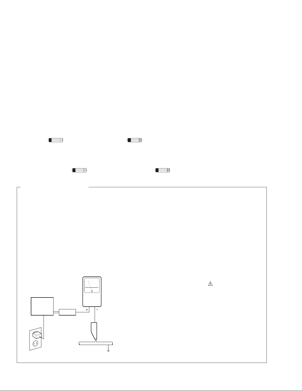
LEAKAGE CURRENT CHECK
Measure leakage current to a known earth ground
(water pipe, conduit, etc.) by connecting a leakage
current tester such as Simpson Model 229-2 or
equivalent between the earth ground and all exposed
metal parts of the appliance (input/output terminals,
screwheads, metal overlays, control shaft, etc.). Plug
the AC line cord of the appliance directly into a 120V
AC 60 Hz outlet and turn the AC power switch on. Any
current measured must not exceed 3.5 mA.
Reading should
not be above
3.5 mA
Earth ground
Device
under
test
Also test with plug
reversed
(Using AC adapter
plug as required)
Leakage
current
tester
Test all exposed
metal surfaces
AC Leakage Test
ANY MEASUREMENTS NOT WITHIN THE LIMITS
OUTLINED ABOVE ARE INDICATIVE OF A POTENTIAL SHOCK HAZARD AND MUST BE CORRECTED BEFORE RETURNING THE APPLIANCE
TO THE CUSTOMER.
2. PRODUCT SAFETY NOTICE
Many electrical and mechanical parts in the appliance have special safety related characteristics. These
are often not evident from visual inspection nor the
protection afforded by them necessarily can be obtained by using replacement components rated for
voltage, wattage , etc. Replacement parts which have
these special safety characteristics are identified in
this Service Manual.
Electrical components having such features are
identified by marking with a
on the parts list in this Service Manual.
The use of a substitute replacement component which
does not have the same safety characteristics as the
PIONEER recommended replacement one, shown in
the parts list in this Service Manual, may create shock,
fire, or other hazards.
Product Safety is continuously under review and
new instructions are issued from time to time. For
the latest information, always consult the current
PIONEER Service Manual. A subscription to, or additional copies of, PIONEER Service Manual may be
obtained at a nominal charge from PIONEER.
on the schematics and
2
PD-F957,PD-F907
2. EXPLODED VIEWS AND PARTS LIST
NOTES : ÷ Parts marked by “ NSP ” are generally unavailable because they are not in our Master Spare Parts List.
÷ The mark found on some component parts indicates the importance of the safety factor of the part.
Therefore, when replacing, be sure to use parts of identical designation.
÷ Screw adjacent to
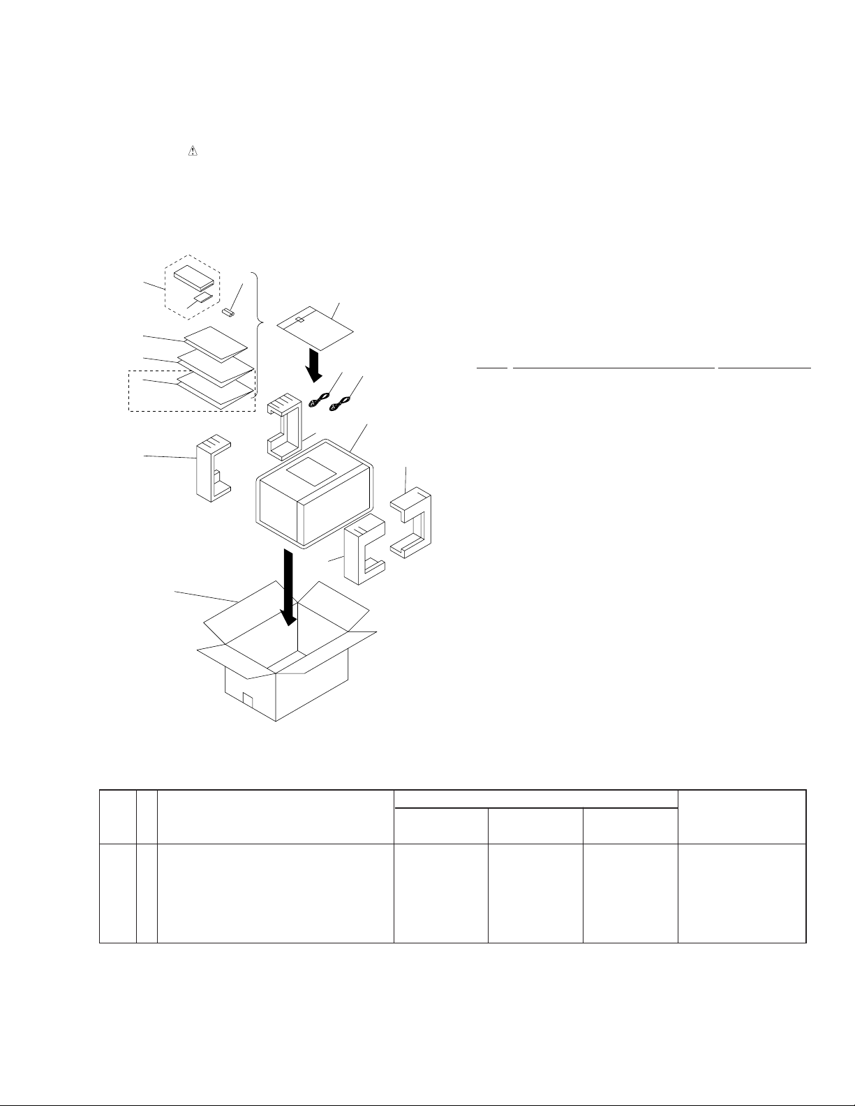
2.1 PACKING
mark on the product are used for disassembly.
∞
10(1/2)
3
4
5
6
7
PD-F907/KC only
11
13
8
(1) PARTS LIST
Mark No. Description Parts No.
1 Control Cable (L=1.0m) PDE1247
2 Output Cable (L=1.0m) PDE1248
3 Remote Control Unit See Contrast table (2)
4 Battery Cover AZN7204
NSP 5 Warranty Card See Contrast table (2)
6 Operating Instructions (English) See Contrast table (2)
7 Operating Instructions (French)) See Contrast table (2)
8 Polyethlene Bag Z21 - 038
9 Styrol Protector F PHA1307
10 Styrol Protector R PHA1308
11 Packing Case See Contrast table (2)
12 Mirror Mat Z23 - 0204
NSP 13 Battery (R6P, AA) VEM - 013
10(2/2)
9(1/2)
Front
2
1
12
9(2/2)
(2) CONTRAST TABLE
PD-F907/KU,KC and PD-F957/KU/CA have the same construction except for the following:
Part No.
Mark No. Symbol & Description Remarks
3 Remote Control Unit PWW1130 PWW1132 PWW1132
NSP 5 Warranty Card ARY1044 ARY1044 ARY1039
6 Operating Instructions (English) PRB1264 PRB1263 PRB1263
7 Operating Instructions (French) Not used Not used PRD1023
11 Packing Case PHG2304 PHG2285 PHG2286
PD-F957/ PD-F907/ PD-F907
KU/CA KU KC
(CU-PD088) (CU-PD080) (CU-PD080)
3
PD-F957,PD-F907
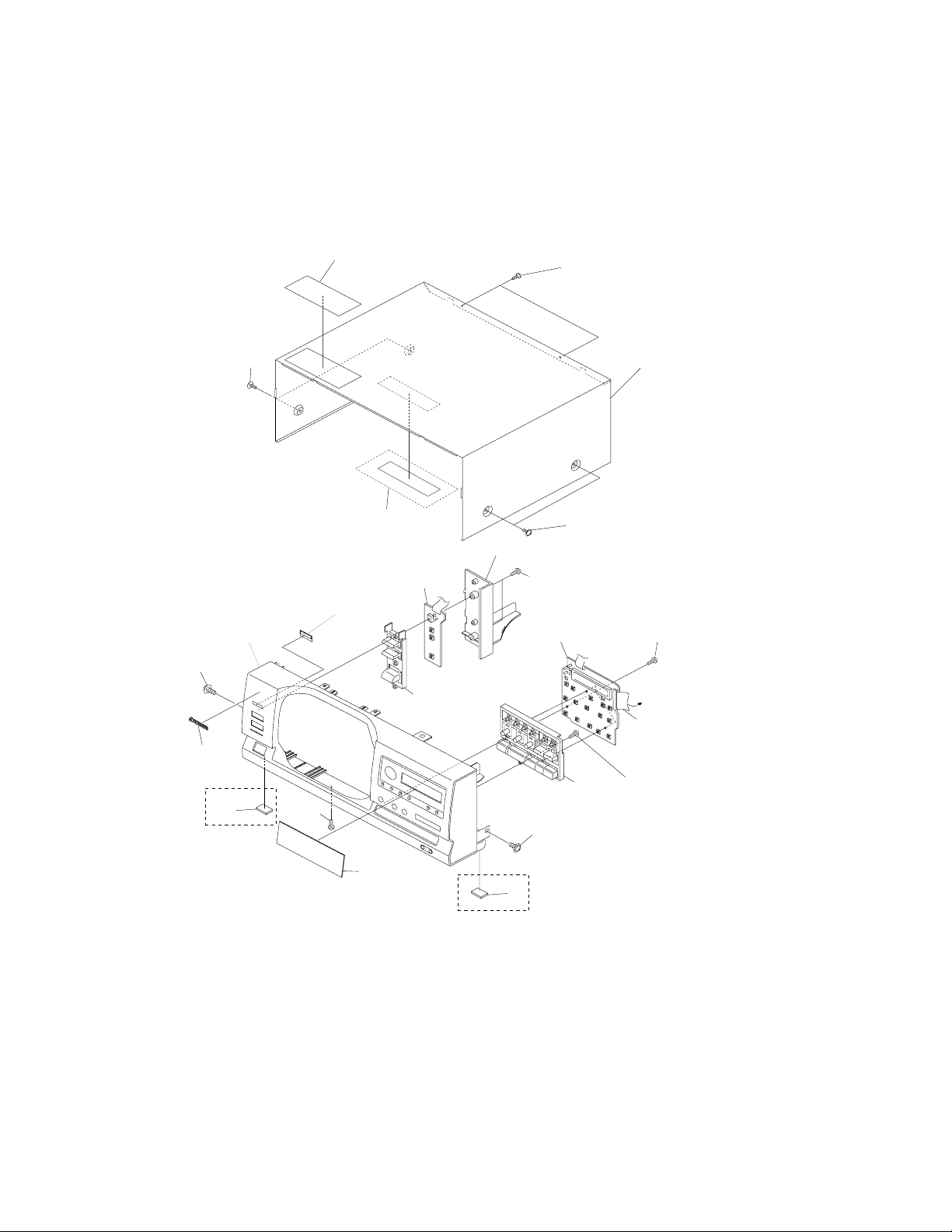
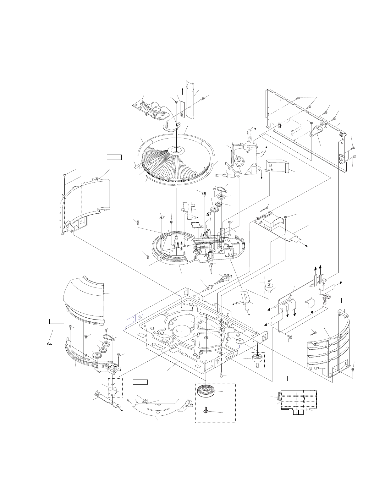
2.2 EXTERIOR
63
50
62
56
55
KU/CA,KU type only
4
54
45
53
68
61
51
62
3
68
A
11
46
68
13
PD-F907 only
44
61
63
47
13
PD-F907 only
4
27
65
PD-F957,PD-F907
D
6
24
67
61
61
61
Note2
26(2/2)
15
63
63
29
28
30
Note1
21(1/2)
52
64
23
57
15
15
32(4/4)
35
32(1/4)
15
42
63
32(3/4)
36
40
39
38
8
H
42
10
Refer to
''2.3 LOADING
MECHANISM
ASSY''
31
32(2/4)
33
64
43
37
15
15
12
H
14
C
25
7
16
J
F
41
E
69
63
34
59
D
A
63
B
1
C
G
G
69
2
E
19
J
21(1/2)
18
61
61
F
Note1
21 (2/2)
63
26(1/2)
17
25
5
34
59
26(2/2)
B
cutting position
Note2
No.26(Hood Base)
cutting
26(1/2)
PD-F957 Only
20
60
22
21(2/2)
cutting
cutting
cutting positionNote1
No.21(Back Fence)
21(1/2)
5
PD-F957,PD-F907
(1) EXTERIOR PARTS LIST
Mark No. Description Parts No. Mark No. Description Parts No.
1 Main Board Assy See Contrast table(2)
2 Power Board Assy See Contrast table(2)
3 Display Board Assy See Contrast table(2)
NSP 4 Switch Board Assy See Contrast table(2)
NSP 5 Door Board Assy See Contrast table(2)
36 Mecha Base PNW2639
37 Gear PNW2641
38 Gear PNW2642
39 Slider PNW2643
40 Lock Lever PNW2644
NSP 6 Center LED Board Assy See Contrast table(2)
NSP 7 Select Motor Board Assy PWZ3324
NSP 8 Sensor Board Assy PWZ3327
NSP 17 Under Base PNA2255
.............
9
10 Cord Stopper CM - 22C
11 F.F.C/30V See Contrast table(2)
12 AC Power Cord PDG1015
13 Rubber Sheet See Contrast table(2)
14 Foot Assy See Contrast table(2)
15 Screw C PBA1106
16 Screw PBA1108
18 Rear Base See Contrast table(2)
19 Stopper Angle PNB1559
Insulator See Contrast table(2)
20
21 Back Fence PNW2671
22 Locking Card Spacer VEC1596
23 Belt PEB1288
24 Cover PNM1294
25 Motor Assy PEA1333
26 Hood Base PNW2633
27 Center Pole PNW2634
28 Gear PNW2641
29 Gear PNW2642
30 Gear Pulley VNL1662
31 Loading Mechanism Assy PXA1589
32 Rack Label PAM1732
33 Belt PEB1288
34 Motor Pulley PNW1634
35 Disc Rack PNW2632
(2) CONTRAST TABLE
41 Mecha Stopper PNW2646
42 Roller PNW2647
43 Gear Pulley VNL1662
44 Control Button PAC1822
45 Power Button PAC1833
46 Name Plate VAM1073
47 Display Window See Contrast table(2)
.............
48
.............
49
50 Operation Panel See Contrast table(2)
51 Bonnet Case PYY1191
52 Hood PNW2732
53 Side Fence PNW2674
54 Sensor Acryl VNK1566
55 65 Label See Contrast table (2)
56 Label PRW1428
57 Label PRW1429
.............
58
59 Slider Motor VXM1033
Screw IBZ30P080FZK
60
61 Screw BBZ30P080FZK
62 Screw FBT40P080FZK
63 Screw IBZ30P060FMC
64 Screw IPZ20P080FMC
65 Screw IPZ30P080FCU
.............
66
67 Screw PPZ30P050FMC
68 Screw PPZ30P100FMC
69 Binder Z09 - 056
PD-F907/KU,KC and PD-F957/KU/CA have the same construction except for the following:
Part No.
Mark No. Symbol & Description Remarks
1 Main Board Assy PWZ3663 PWZ3400 PWZ3400
2 Power Board Assy PWZ3668 PWZ3414 PWZ3414
3 Display Board Assy PWZ3672 PWZ3426 PWZ3426
NSP 4 Switch Board Assy PWZ3675 PWZ3432 PWZ3432
NSP 5 Door Board Assy PWZ3681 PWZ3441 PWZ3441
NSP 6 Center LED Board Assy PWZ3683 PWZ3443 PWZ3443
11 F.F.C/30V PDD1186 PDD1167 PDD1167
13 Rubber Sheet Not Used AEB1111 AEB1111
14 Foot Assy REC1263 AEC1531 AEC1531
18 Rear Base PNA2405 PNA2389 PNA2389
20 Insulator PNW2766 Not Used Not Used
47 Display Window PAM1752 PAM1725 PAM1725
50 Operation panel PNW2786 PNW2773 PNW2773
55 65 Label ORW1069 ORW1069 Not used
6
PD-F957/ PD-F907/ PD-F907/
KU/CA KU KC
(40P F.F.C) (32P F.F.C) (32P F.F.C)
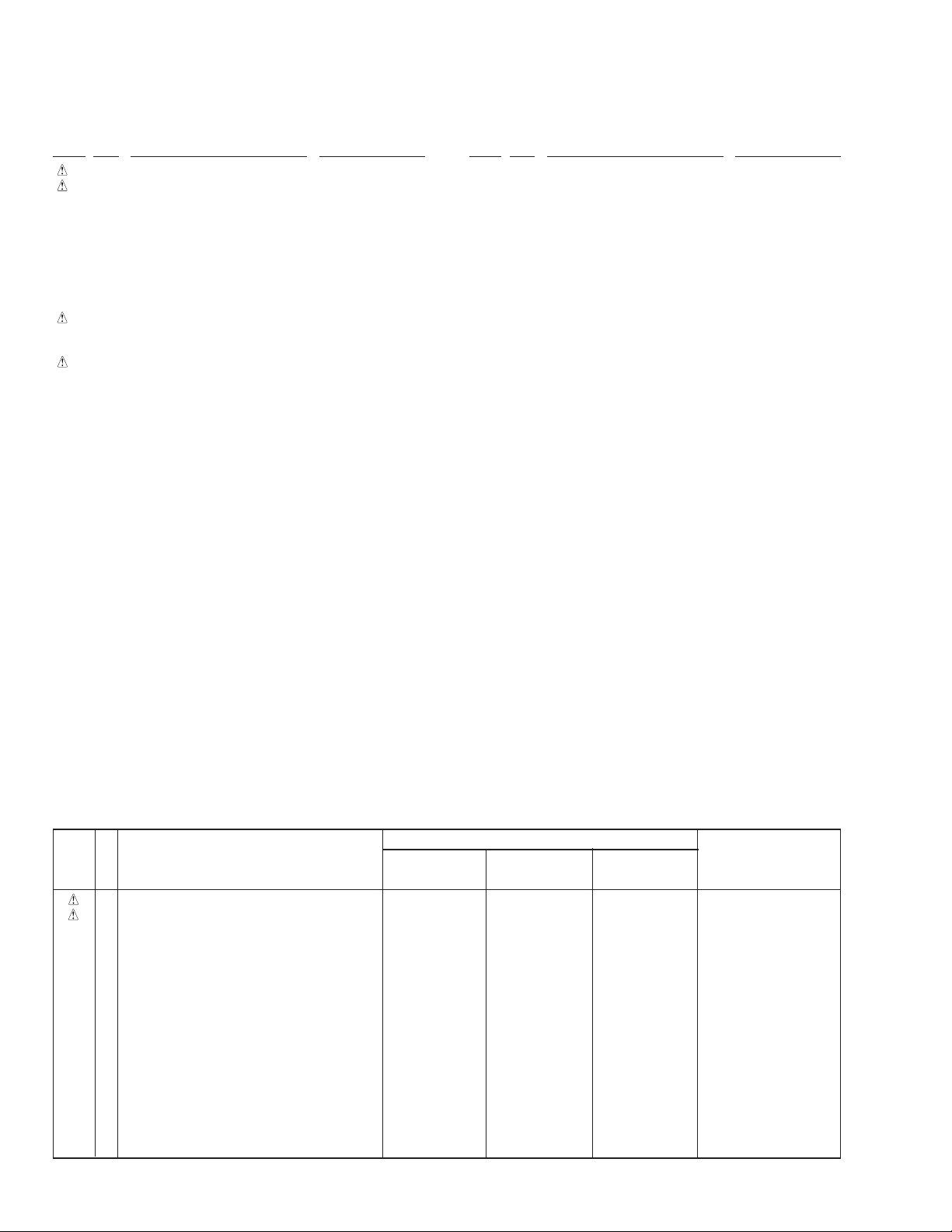
2.3 LOADING MECHANISM ASSY
PD-F957,PD-F907
7

PD-F957,PD-F907
LOADING MECHANISM ASSY PARTS LIST
Mark No. Description Parts No.
…………
1
…………
2
NSP 3 Loading Motor Board Assy PWZ3337
NSP 4 Load SW Board Assy PWZ3334
NSP 14 Servo Stopper S ANB7047
5 Arm A Spring2 ABH7124
6 Gear Plate Spring ABH7051
7 Clamp Spring ABH7107
…………
8
…………
9
10 Loading Belt AEB7029
…………
11
…………
12
…………
13
15 Loading Base ANW7086
16 Cam Cover ANW7052
17 Motor Holder ANW7053
18 Sensor Holder ANW7119
19 Float Base 96 PNW2700
20 Clamper Holder ANW7117
21 Arm (A) ANW7057
22 Arm (B) ANW7058
23 Drive Plate ANW7059
24 Arm Plate ANW7060
25 Gear Plate ANW7111
26 Gear Pulley (B) ANW7062
27 Gear A ANW7063
28 Drive Gear ANW7064
…………
29
…………
30
…………
31
…………
32
…………
33
34 Roller B ANW7075
35 Motor Pulley PNW1634
36 Clamper PNW2743
37 Float Spring ABH7049
38 Connector Assy (4P) RDE1043
39 Float Rubber AEB7028
NSP 40 Servo Mechanism Assy GM PXA1591
41 Screw IPZ20P080FMC
…………
42
…………
43
44 Motor Assy AEA7006
45 Loading Motor VXM1034
46 16P FFC/30V PDD1180
Froil (for Service) GYA1001
Ha Narl (for Service) GEM1016
8
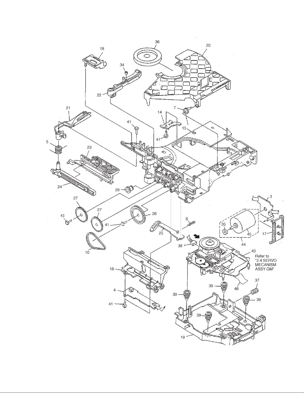
2.4 SERVO MECHANISM ASSY GM
PD-F957,PD-F907
How to Install the Disc Table
Use nipper or other tool to cut the three sections marked
1
A
in figure . Then remove the spacer
While supporting the spindle motor shaft with the
2
stopper, put spacer on top of the yoke M, and stick the
disc table on top (takes about 9kg pressure). Detach the
spacer.
1
Spacer
A
1
Float Base
2
Spacer
Yoke M
Spacer Setting
Position
Carriage Base
Spindle Motor
(Pressure of about 9 kg)
Disc Table
0.9mm
±0.05mm
1.2mm
Stopper
6.9mm
9

PD-F957,PD-F907
SERVO MECHANISM ASSY GM PARTS LIST
Mark No. Description Parts No.
1 Gear 1 PNW2052
2 Gear 2 PNW2053
3 Gear 3 PNW2054
4 Carriage Base PNW2699
5 Pickup Assy - S PEA1335
6 D.C. Motor Assy (SPINDLE) PEA1235
7 Carriage DC Motor Assy PEA1246
8 Pinion Gear PNW2055
9 Carriage DC Motor/0.3W PXM1027
10 Disc Table Assy PEA1314
11 Mechanism Board Assy PWX1192
12 Guide Bar PLA1094
…………
13
14 Screw JFZ17P025FZK
15 Screw JFZ20P040FMC
16 Washer WT12D032D025
17 Clamp Magnet PMF1014
18 Yoke M PNB1312
NSP 19 Disc Table PNW2410
NSP 20 Float Angle ANB7020
21 Gear Stopper PNB1303
22 Screw BPZ20P060FMC
23 Screw BPZ26P100FMC
24 PU Rack Spring ABH7077
25 Rack Holder PNW2056
10
1
23
4
PD-F957,PD-F907
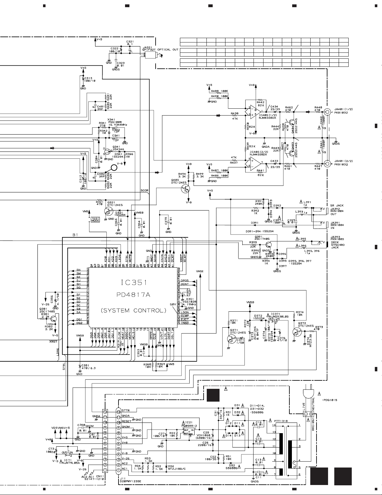
3. SCHEMATIC DIAGRAM
Note: When ordering service parts, be sure to refer to "EXPLODED VIEW AND PARTS LIST" or "PCB PARTS LIST".
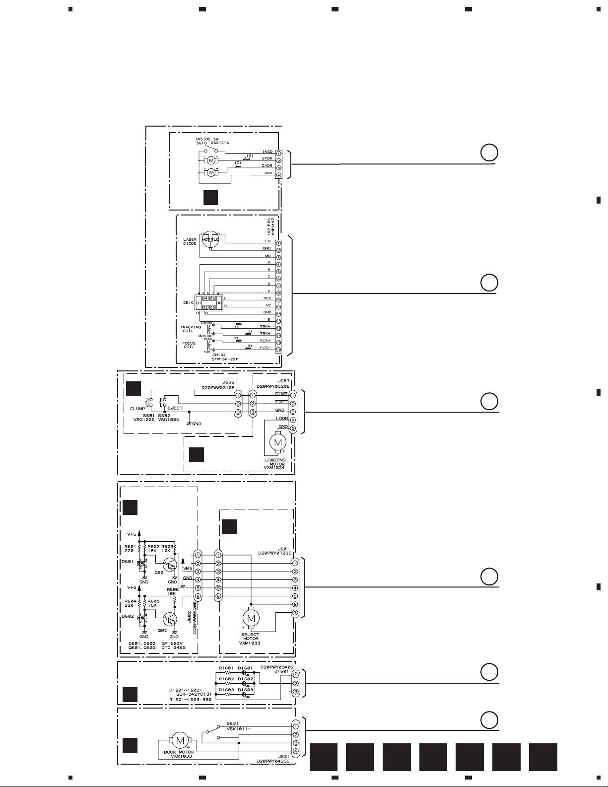
3.1 MECHANISM BOARD ASSY,SENSOR BOARD ASSY,LOAD SW BOARD ASSY,SELECT
MOTOR BOARD ASSY,LOADING MOTOR BOARD ASSY,CENTER LED BOARD ASSY,
DOOR BOARD ASSY AND PICKUP ASSY
A
SPINDLE
MOTOR
ASSY
PEA1235
CARRIAGE
MOTOR
ASSY
PEA1246
PICK UP ASSY
(PEA1335)
(PXA1591)
SERVO MECHANISM ASSY GM
LOAD SW BOARD
ASSY (PWZ3334 )
B
A
MECHANISM
BOARD ASSY
(PWX1192)
CN610
A
B
B
C
LOADING MECHA
BOARDASSY
(PWX1474)
SENSOR BOARD
ASSY
(PWZ3327)
D
CENTER LED BOARD ASSY
PD-F957/KU/CA:(PWZ3683)
PD-F907/KU,KC:(PWZ3443)
C
F
DOOR BOARD ASSY
PD-F957/KU/CA:(PWZ3681)
PD-F907/KU,KC:(PWZ3441)
LOADING MOTOR
BOARD ASSY
(PWZ3337)
SELECT MOTOR
BOARD ASSY
(PWZ3324)
E
C
D
E
D
F
G
E F GA B C D
1
2
3
4
11
1
234
PD-F957,PD-F907
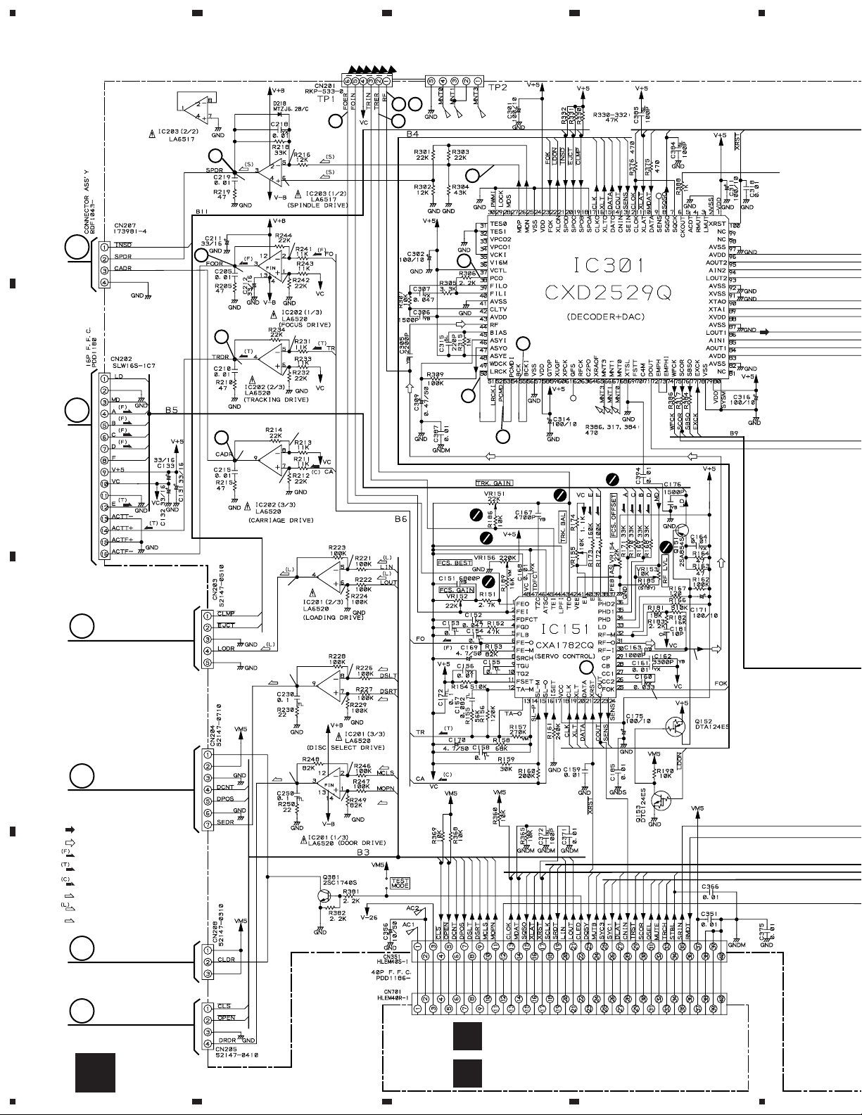
3.2 MAIN BOARD ASSY AND POWER BOARD ASSY (FOR PD-F957)
2
23
43
1.6V
1.6V
1.7V
1.8V
1.8V
1.6V
1.6V
1.7V
33
53
16
18
19
(F)
(F)
(F)
(F)
(T)
(T)
0V
A
A
B
B
7
-O.7V
5
OV
6
OV
8
0.2V
0V
0V
C
0V
0V
(SEL)
C
0V
0V
D
SIGNAL ROUTE
: AUDIO SIGNAL
: EFM SIGNAL
: FOCUS SERVO LOOP
: TRACKING SERVO LOOP
: CARRIAGE SERVO LOOP
(S)
: SPINDLE DRIVE
: LOADING DRIVE
(D)
: DOOR DRIVE
(D)
0V
(SEL)
(SEL)
0V
(D)
(D)
23
3.4V
5.0V
E
D
12
F
DISPLAY BOARD ASSY
L
H
1234
M
(PWZ3672)
SWITCH BOARD ASSY
(PWZ3675)
5
67
8
PD-F957,PD-F907
IC301(CXD2529Q) :PLAY MODE
PIN No.
Voltage(V)
PIN No.
Voltage(V)
PIN No.
Voltage(V)
10
1 2 3 - 4 7 8 9 10 11 12 13 14 16 17 23 24 25
5
26 27 38 39 40 41 42 43 44 45 46 47 48 50-55 56 57
5
2.6-2.7
61 71 75 78 79 82 83 87 88 89-9084-86 91-92 93-95 9796 100
5
2.5 2.5 2.5 2.5
4.7
2.5
3.1 3.12.5 2.5 0.9 2.5 2.5 2.5
00 505 0 5 0 50 5
0 50
1.6V
1.6V
55550 00
4.4 4.7 4.7 4.71.2-1.41.2-1.3
55
0V
0V
0.05
0V
-9.2
0V
-9.2
0V
LINE OUT
JACK
A
B
H
MAIN BOARD ASSY
(PWZ3663)
C
AC120V
60Hz
AC POWER CORD
:PDG1015
POWER BOARD ASSY
I
(PWZ3668)
D
P0WER TRANSFORMER
5
6
7
H
8
I
13
1
234
PD-F957,PD-F907
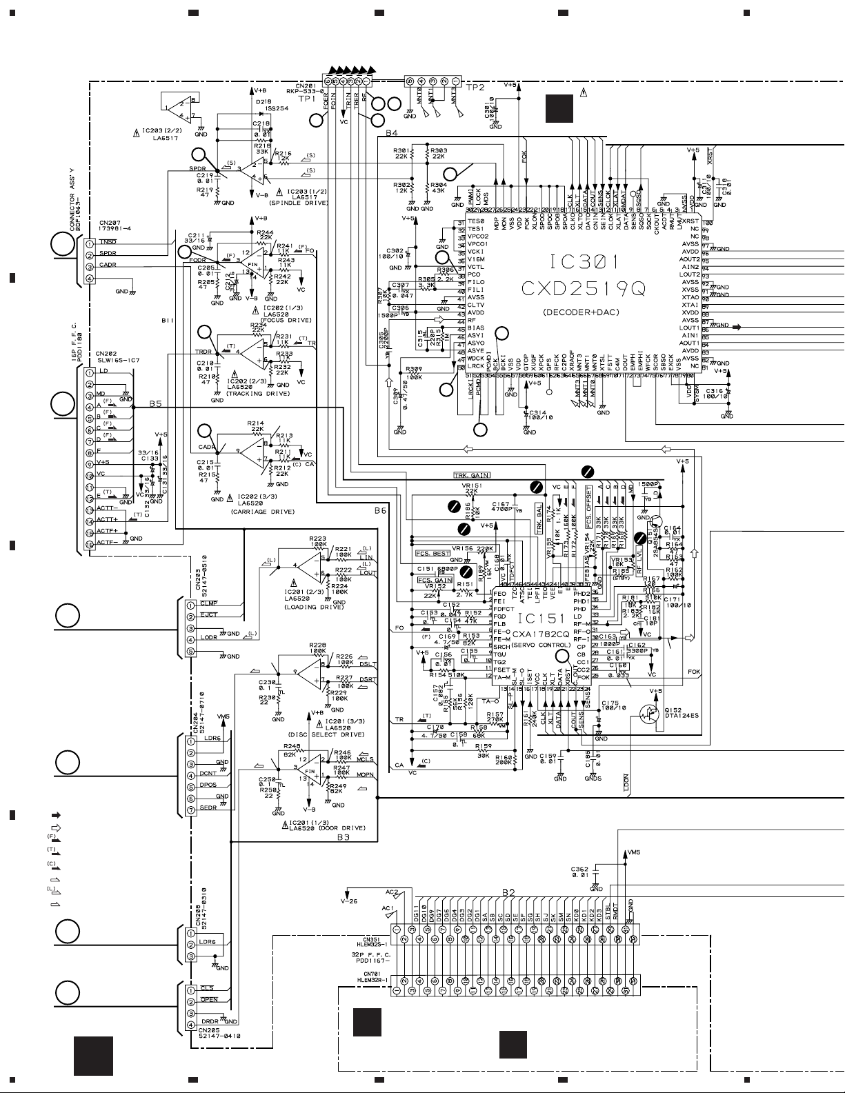
3.3 MAIN BOARD ASSY AND POWER BOARD ASSY (FOR PD-F907)
2
23
43
J
MAIN BOARD ASSY
(PWZ3400)
1.6V
1.6V
1.7V
1.8V
1.8V
1.6V
1.6V
1.7V
33
53
16
18
19
(F)
(F)
(F)
(F)
(T)
(T)
0V
A
A
B
B
7
-O.7V
5
OV
6
OV
8
0.2V
C
D
C
D
SIGNAL ROUTE
: AUDIO SIGNAL
: EFM SIGNAL
: FOCUS SERVO LOOP
: TRACKING SERVO LOOP
: CARRIAGE SERVO LOOP
(S)
: SPINDLE DRIVE
: LOADING DRIVE
(D)
: DOOR DRIVE
E
(SEL)
(D)
0V
0V
0V
0V
0V
(SEL)
0V
0V
(SEL)
0V
(D)
(D)
23
3.4V
5.0V
14
F
DISPLAY BOARD ASSY
N
(PWZ3426)
SWITCH BOARD ASSY
O
(PWZ3432)
J
1234
5
67
8
PD-F957,PD-F907
IC301(CXD2519Q) :PLAY MODE
PIN No.
Voltage(V)
PIN No.
Voltage(V)
PIN No.
Voltage(V)
10
1 2 3 - 4 7 8 9 10 11 12 13 14 16 17 23 24 25
5
26 27 38 39 40 41 42 43 44 45 46 47 48 50-55 56 57
5
2.6-2.7
61 71 75 78 79 82 83 87 88 89-9084-86 91-92 93-95 9796 100
5
4.7
2.5
3.1 3.12.5 2.5 0.9 2.5 2.5 2.5
00 505 0 5 0 50 5
2.5 2.5 2.5 2.5
0 50
1.6V
1.6V
55550 00
4.4 4.7 4.7 4.71.2-1.41.2-1.3
55
0V
0V
0.05
0V
-9.2
0V
-9.2
0V
LINE OUT
JACK
A
B
POWER BOARD ASSY
K
(PWZ3414)
(BACK UP)
POWER TRANSFORMER
AC 120V
60 Hz
AC POWER CORD
C
D
J
5
6
7
8
K
15
1
234
PD-F957,PD-F907
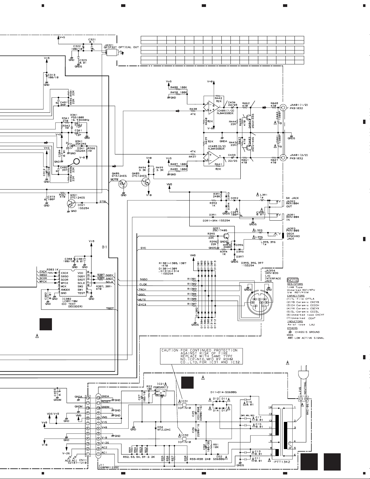
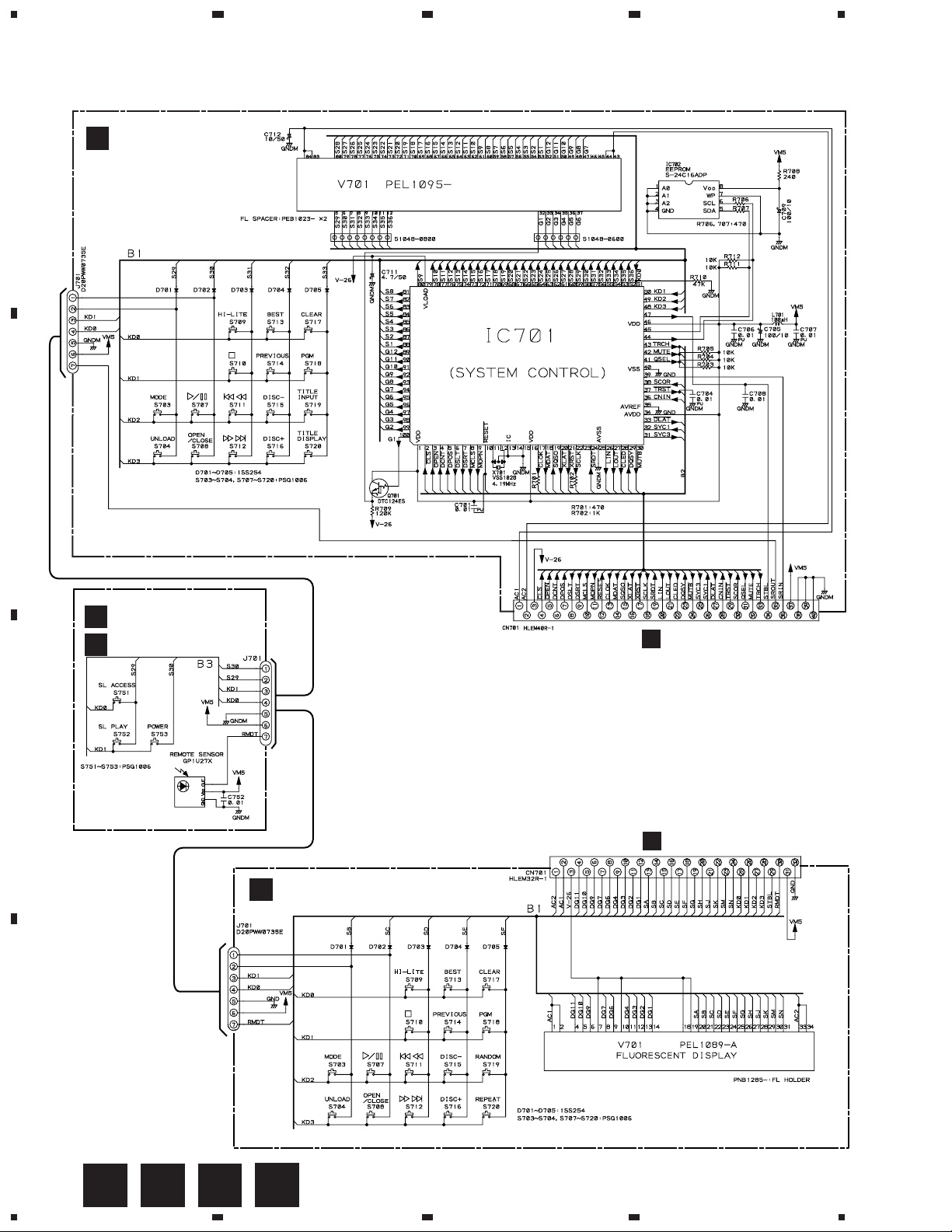
3.4 DISPLAY BOARD ASSY AND SWITCH BOARD ASSY
L
A
B
DISPLAY BOARD ASSY
PD-F957/KU/CA:(PWZ3672)
PD4934B
SWITCH BOARD ASSY
PD-F957/KU/CA:(PWZ3675)
M
H
PD-F907/KU,KC:(PWZ3432)
O
SWITCHES
SWITCH BOARD ASSY
S751 : SL ACCESS
S752 : SL PLAY
S753 : POWER STAND/ON
C
DISPLAY BOARD ASSY
N
PD-F907/KU,KC:(PWZ3426)
DISPLAY BOARD ASSY
S703 : MODE
S704 : UNLOAD
S707 : 6
S708 : OPEN/CLOSE
S709 : HI-LITE
S710 : 7
S711 : 4 1
S712 : ¡ ¢
S713 : BEST
S714 : PREVIOUS
CN351
S715 : DISC –
S716 : DISC +
S717 : CLEAR
S718 : PGM
S719 : TITLE INPUT (PD-F957)
: RANDOM (PD-F907)
S720 : TITLE DISPLAY (PD-F957)
: REPEAT (PD-F907)
J
CN351
D
16
L
M N
1234
O
PD-F957,PD-F907
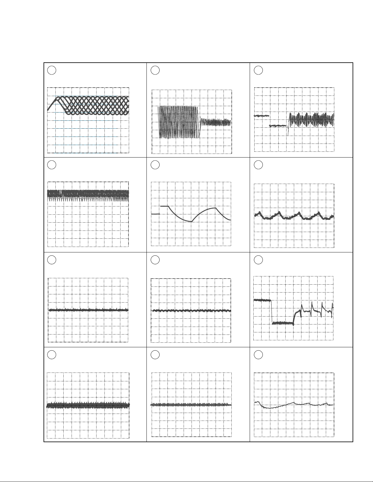
Waveforms
Note: The encircled numbers denote measuring point in the schematic diagram.
TP1-Pin 1: PLAY MODE (RF)
2
500mV/div 500nsec/div
– VC
TP1-Pin 1: TRACK SEARCH MODE
25
(RF)
500 mV/div 200 µsec/div
– VC
TP1-Pin 2: 50T - JUMP (*1) MODE
(TRER)
200mV/div 1msec/div
– VC
IC202-Pin 3: FOCUS-IN (*2) MODE
(FODR)
1V/div 200msec/div
– GND
∗1 50T-JUMP: After switching to the pause mode, press
the manual search key.
∗2 FOCUS-IN: Press the play key without loading a disc.
IC202-Pin 4: 50T - JUMP (*1) MODE
6'4'
(TRDR)
500mV/div 1msec/div
– GND
IC203-Pin 3: PLAY MODE (SPDR)
7
1V/div 50msec/div
– GND
TP1-Pin 6: PLAY MODE (FOER)
3
100mV/div 10msec/div
TP1-Pin 2: PLAY MODE (TRER)
4
200mV/div 1msec/div
– VC
– VC
IC202-Pin 3: PLAY MODE (FODR)
5
1V/div 1msec/div
IC202-Pin 4: PLAY MODE (TRDR)
6
500mV/div 1msec/div
– GND
– GND
IC203-Pin 3: TRACK SEARCH MODE
7
(SPDR)
2V/div 50msec/div
IC202-Pin 9: PLAY MODE (CADR)
8
0.2V/div 2sec/div
– GND
– GND
17
 Loading...