

Pioneer PD-F19 Service Manual

ORDER NO.
RRV2048
FILE-TYPE CD PLAYER
PD-F19
¶ Refer to the service manual RRV2001 for PD-F1007/KU.
THIS MANUAL IS APPLICABLE TO THE FOLLOWING MODEL(S) AND TYPE(S).
Type
KU AC120V
Model
PD-F19
Power Requirement
CONTENTS
1. CONTRAST OF MISCELLANEOUS PARTS .....2
2. SCHEMATIC DIAGRAM.....................................6
3. PCB CONNECTION DIAGRAM .......................12
Remarks
PIONEER ELECTRONIC CORPORATION 4-1, Meguro 1-Chome, Meguro-ku, Tokyo 153-8654, Japan
PIONEER ELECTRONICS SERVICE, INC. P.O. Box 1760, Long Beach, CA 90801-1760, U.S.A.
PIONEER ELECTRONIC (EUROPE) N.V. Haven 1087, Keetberglaan 1, 9120 Melsele, Belgium
PIONEER ELECTRONICS ASIACENTRE PTE. LTD. 501 Orchard Road, #10-00 Wheelock Place, Singapore 238880
PIONEER ELECTRONIC CORPORATION 1998
T–ZZR OCT. 1998 Printed in Japan
PD-F19
1. CONTRAST OF MISCELLANEOUS PARTS
NOTES : ÷ Parts marked by “ NSP ” are generally unavailable because they are not in our Master Spare Parts List.
÷ The
÷ Reference Nos. indicate the pages and Nos. in the service manual for the base model.
÷ When ordering resistors, first convert resistance values into code form as shown in the following examples.
7 CONTRAST TABLE
PD-F19/KU and PD-F1007/KU are constructed the same except for the following:
Ref.
Mark Symbol and Description
No.
ASSEMBLIES
NSP MOTHER BOARD ASSY PWM2252 PWM2256
P5-1 MAIN BOARD ASSY PWZ3822 PWZ3826
mark found on some component parts indicates the importance of the safety factor of the part.
Therefore, when replacing, be sure to use parts of identical designation.
Ex. 1 When there are 2 effective digits (any digit apart from 0), such as 560 ohm and 47k ohm (tolerance is shown by
J = 5%, and K = 10%).
1
560 Ω = 56 × 10
47k Ω = 47 × 10
= 561................................................... RD1/4PU 5 6 1 J
3
= 473 .................................................. RD1/4PU 4 7 3 J
0.5 Ω = R50 ...................................................................... RN2H Â 5 0 K
1 Ω = 1R0 ......................................................................... RS1P 1 Â 0 K
Ex. 2 When there are 3 effective digits (such as in high precision metal film resistors).
1
5.62k Ω = 562 × 10
= 5621 ........................................... RN1/4PC 5 6 2 1 F
Part No.
PD-F1007/KU type PD-F19/KU type
KEY BOARD ASSY Not used PWZ3836 No.1
Remarks
P9-1 DISPLAY BOARD ASSY PWZ3839 PWZ3840
P5-2 POWER BOARD ASSY PWZ3852 PWZ3855
P3-1 Styrol Protector F PHA1325 PHA1336
P3-2 Styrol Protector R PHA1326 PHA1337
P3-3 Packing Case PHG2316 PHG2340
P3-6 Operating lnstructions(English) PRB1271 PRB1276
P3-12 NSP Warranty Card ARY7023 ARY1026
P5-8 Bonnet Case PYY1255 PYY1263
P5-9 Rear Base PNA2424 PNA2457
P5-17 Hood PNW2793 PNW2872
P9-4 F·F·C /30V Connector PDD1189 PDD1188
P9-9 Name Plate PAM1776 PAN1376
P9-16 Operation Panel PNW2794 PNW2818
NSP SUB BOARD ASSY PWX1576 PWX1579
PACKING
EXTERIOR
Side Mole L Not used PNA1373 No.2
Side Mole R Not used PAN1374 No.3
Side Wood L Not used PMM1043 No.4
Side Wood R Not used PMM1044 No.5
Wood Collar Not used PNW1238 No.6
NSP Spacer Not used PNM1331 No.7
Screw Not used PBA1103 No.8
FRONT PANEL SECTION
NOTE: • The numbers in the remarks correspond to the numbers on the exploded diagram, Refer to "EXPLODED VIEWS".
• For ASSEMBLES, Refer to " CONTRAST OF PCB ASSEMBLIES" and "2.SCHEMATIC DIAGRAM".
2

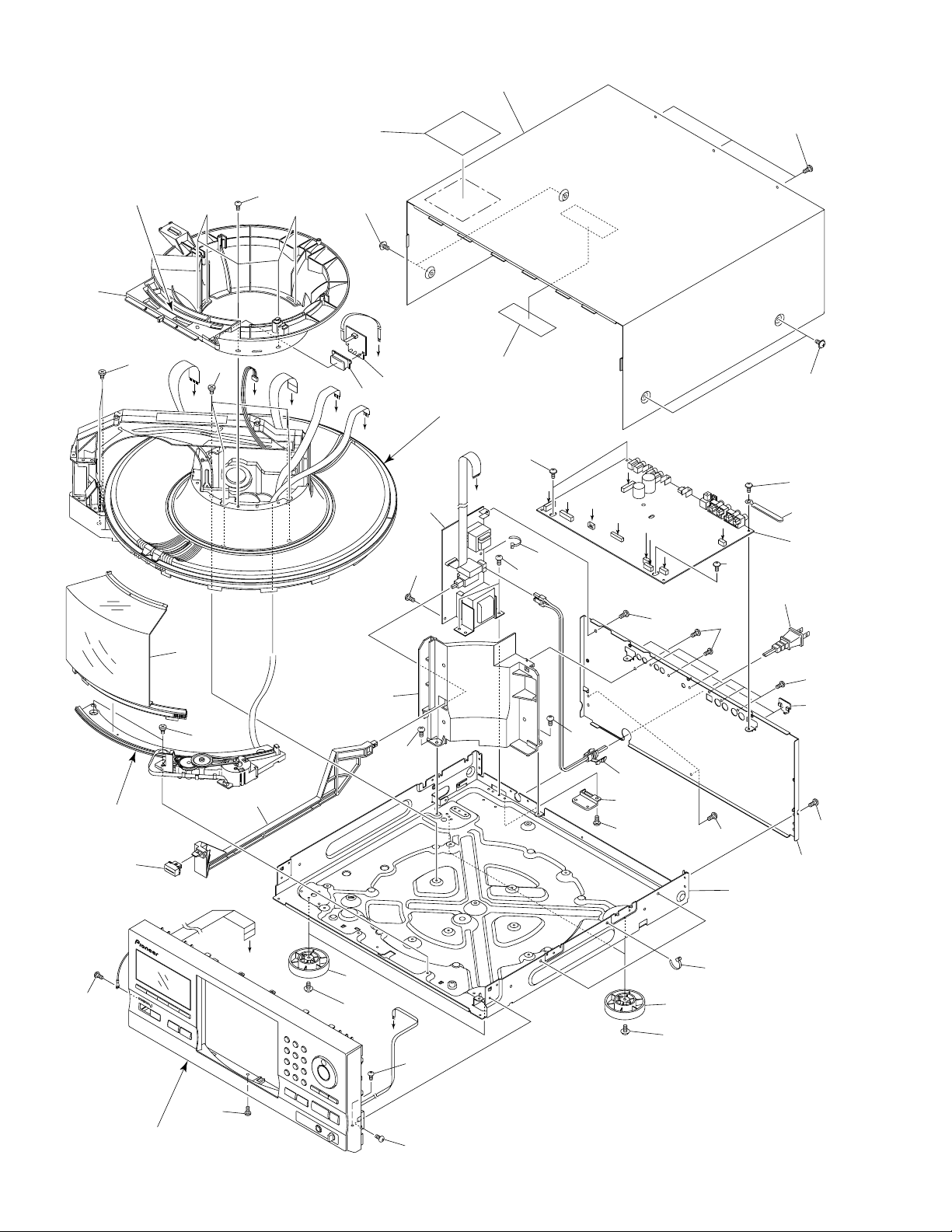
EXPLODED VIEWS
Operation Panel
KEY BOARD ASSY
PPZ30P050FMC
Bonnet Case
No.4
No.8
No.6
No.3
No.1
No.7
No.5
BBZ30P080FZK
BBZ30P080FZK
No.7
No.2
No.6
No.6
No.8
No.8
RNH-184
EXTERIOR SECTION
PD-F19
3
PD-F19
CONTRAST OF PCB ASSEMBLIES
L F
DISPLAY BOARD ASSY
PWZ3840 and PWZ3839 are constructed the same except for the following:
Mark Symbol and Description
CN701 HLEM16R-1 HLEM18R-1
CN702 Not used 52151-0410
R708, R709 Not used RD1/4PU471J
Note : Refer to 2. SCHEMATIC DIAGRAM.
O F
POWER BOARD ASSY
PWZ3839 PWZ3840
Part No.
PWZ3855 and PWZ3852 are constructed the same except for the following:
Mark Symbol and Description
PWZ3852 PWZ3855
IC71 Not used PQ05RA1
D71 , D72 Not used S5688G
C71 Not used CEAT332M16
C72 Not used CEAT101M10
R71 Not used RD1/4PU103J
R72 Not used RD1/4PU471J
J11 D20PDY0925B D20PDY0925G
J71 Not used D20PDY0315E
3P CABLE HOLDER Not used 51048-0300
NSP HEAT SINK Not used RNE1011
Note : Refer to 2. SCHEMATIC DIAGRAM.
Part No.
Remarks
Remarks
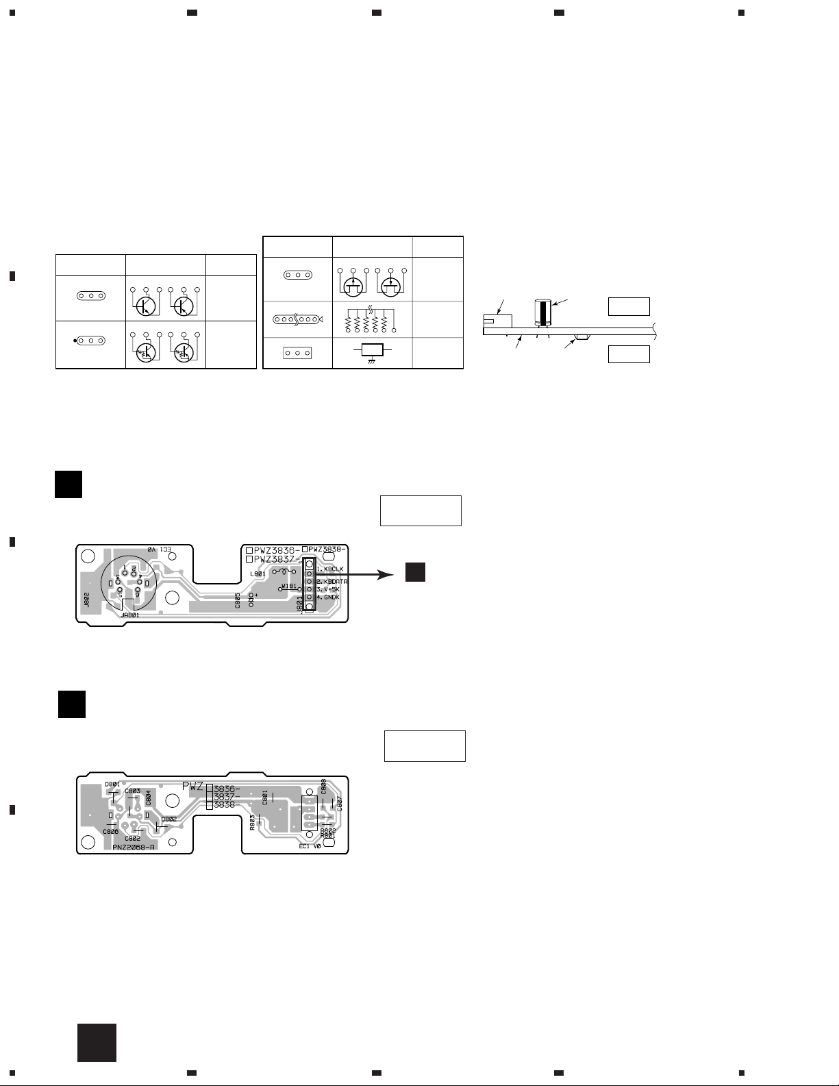
PCB PARTS LIST
Mark No. Description Part No. Mark No. Description Part No.
KEY BOARD ASSY
Q
SEMICONDUCTORS
D801, D802 DA204K
CAPACITORS
C805 CEAL101M6R3
C801– C804, C806 CKSQYF104Z50
RESISTORS
R801– R803 RS1/10S0R0J
OTHERS
J801 4P WIRE 2mmP D20PWY0455E
NSP J802 LEAD WIRE UNIT PDF1012
JA801 MIN DIN 6P SOCKET RKN1038
MAIN BOARD ASSY (PWZ3826)
K F
SEMICONDUCTORS
IC151 CXA1782CQ
IC301 CXD2529Q
IC35, IC36 ICP-N10
IC203 LA6517
IC201, IC202 LA6520
IC302 LC89170M
IC406 M5218AFP
IC352
IC405, IC407, IC408 NJM4558MD
IC23 NJM79M05FA
IC351 PD4996C
IC341 PD0236AM
IC21 PQ05RR12
IC401 PE8001A
IC25 S-806E
M5M51008BFP-70LL
4

PD-F19
Mark No. Description Part No.
IC951 TC74HC157AF
IC331 TC74HCU04AF
Q151 2SA854S
Q391 2SC1740S
Q362, Q381 2SC2412K
Q351, Q403, Q404, Q413, Q414 2SD2144S
Q423, Q424 2SD2144S
Q152, Q363, Q382, Q406, Q416 DTA124EK
Q426 DTA124EK
Q405, Q415, Q425, Q451 DTC124EK
D351, D352, D391–D397, D958 1SS254
D401–D404, D951, D953, D956 DA204K
D957, D959 DA204K
D54 MTZJ24B
D11–D14, D52 S5688G
D218 UDZS6.2B
COILS AND FILTERS
L351 LAU100J
L391, L395, L396 LAU1R0J
L334 (COIL) PTL1003
CAPACITORS
C449, C450 CCCSL101J50
C181 CCSQCH100D50
C361, C386, C405–C407 CCSQCH101J50
C315 CCSQCH221J50
C403 CCSQCH240J50
C404 CCSQCH300J50
C332 CCSQCH390J50
C171, C175, C27, C29 CEAT101M10
C301, C302, C311–C314, C316 CEAT101M10
C322, C351, C365, C413, C414 CEAT101M10
C51 CEAT101M35
C52 CEAT101M50
C427–C428, C433–C434, C439–C440 CEAT220M25
C131–C133, C211, C212 CEAT330M16
C169, C170, C415, C416 CEAT4R7M50
C335 CEAT470M25
C22 CEATR22M50
C309 CEATR47M50
C954 CFTLA104J50
C441, C442 CKCYB102K50
C1429, C1430, C1435–C1438 CKCYB152K50
C317 CKCYF103Z50
C359, C398, C951, C952 CKCYF473Z50
C163 CKSQYB102K50
C156, C161, C164, C168, C218 CKSQYB103K50
C153–C155, C158, C230, C250 CKSQYB104K25
C176, C306 CKSQYB152K50
C305 CKSQYB222K50
C162 CKSQYB332K50
C160 CKSQYB333K25
Mark No. Description Part No.
C151 CKSQYB682K50
C157 CKSQYB823K25
C159, C185, C191, C205, C210 CKSQYF103Z50
C215, C219, C303, C308, C318 CKSQYF103Z50
C331, C334, C343, C344, C352 CKSQYF103Z50
C353, C362, C363, C381, C382 CKSQYF103Z50
C401, C402, C408, C409, C461 CKSQYF103Z50
C953 CKSQYF103Z50
C321, C336, C339, C411, C412 CKSQYF104Z50
C1431, C1432 CKSQYF104Z50
C354 (0.1F/5.5V) PCH1133
C25, C26 (4700µF/16V) PCH1135
RESISTORS
R56–R59 RD1/4PU241J
R52–R54 RD1/4PU272J
R496, R499, R973, R974 RD1/4PU332J
R977, R978 RD1/4PU332J
R163, R164, R470, R471 RD1/4PU470J
R441, R442, R489, R490 RN1/10SE1002D
R437, R438 RN1/10SE1801D
R459, R460, R463, R464 RN1/10SE2202D
R451– R456 RN1/10SE4702D
VR153, VR155 (10kΩ) VCP1156
VR151, VR152, VR154 (22kΩ) VCP1158
VR156 (220kΩ) VCP1164
Other Resistors RS1/10S J
OTHERS
CN207 MT 4P CONNECTOR 173981-4
CN12
CN208, CN401
CN205
CN203
CN11, CN204
JA401, JA402 JACK DKB1031
JA321 OPTICAL LINK OUT GP1F32T
CN351 CONNECTOR HLEM18S-1
JA331 1P JACK PKB1028
JA393 JACK PKN1005
J391–J392, J951–J952REMOTE JACK RKN1004
CN201 6P CONNECTOR RKP-533
CN202 CONNECTOR SLW16S-1C7
X401 XTAL. RES. (16.9344MHz) PSS1008
X351 CERAMIC RESONATOR VSS1028
PCB BINDER VEF1040
SCREW PLATE VNE1948
3P JUMPER CONNECTOR
3P JUMPER CONNECTOR
4P JUMPER CONNECTOR
5P JUMPER CONNECTOR
9P JUMPER CONNECTOR
52147-0310
52147-0310
52147-0410
52147-0510
52147-0910
C167 CKSQYB472K50
C152, C307 CKSQYB473K25
5
1
MAIN
BOARD
ASSY
(PWZ3826)
F
J651
A
CN610
to PICUP ASSY
1.8V
1.8V
-0.7V
1.6V
1.6V
0V
1.6V
1.6V
0V
1.7V
1.7V
0.2V
0V
0V
0V
CAUTION : FOR CONTINUED PROTECTION AGAINST RISK OF FIRE,
REPLACE ONLY WITH SAME TYPE NO. ICP-N10, MFD BY
ROHM CO., FOR IC35 AND IC36.
K
(S)
(S)
(S)
(F)
(F)
(F)
(F)
(F)
(F)
(T)
(T)
(T)
(T)
(C)
(L)
(L)
(L)
(SEL)
(SEL)
(SEL)
(F)
(F)
(F)
(F)
(F)
(T)
(T)
7
5
6
8
2 23
4
3
33
53
18
19
16
K-b
K-a
PD-F19
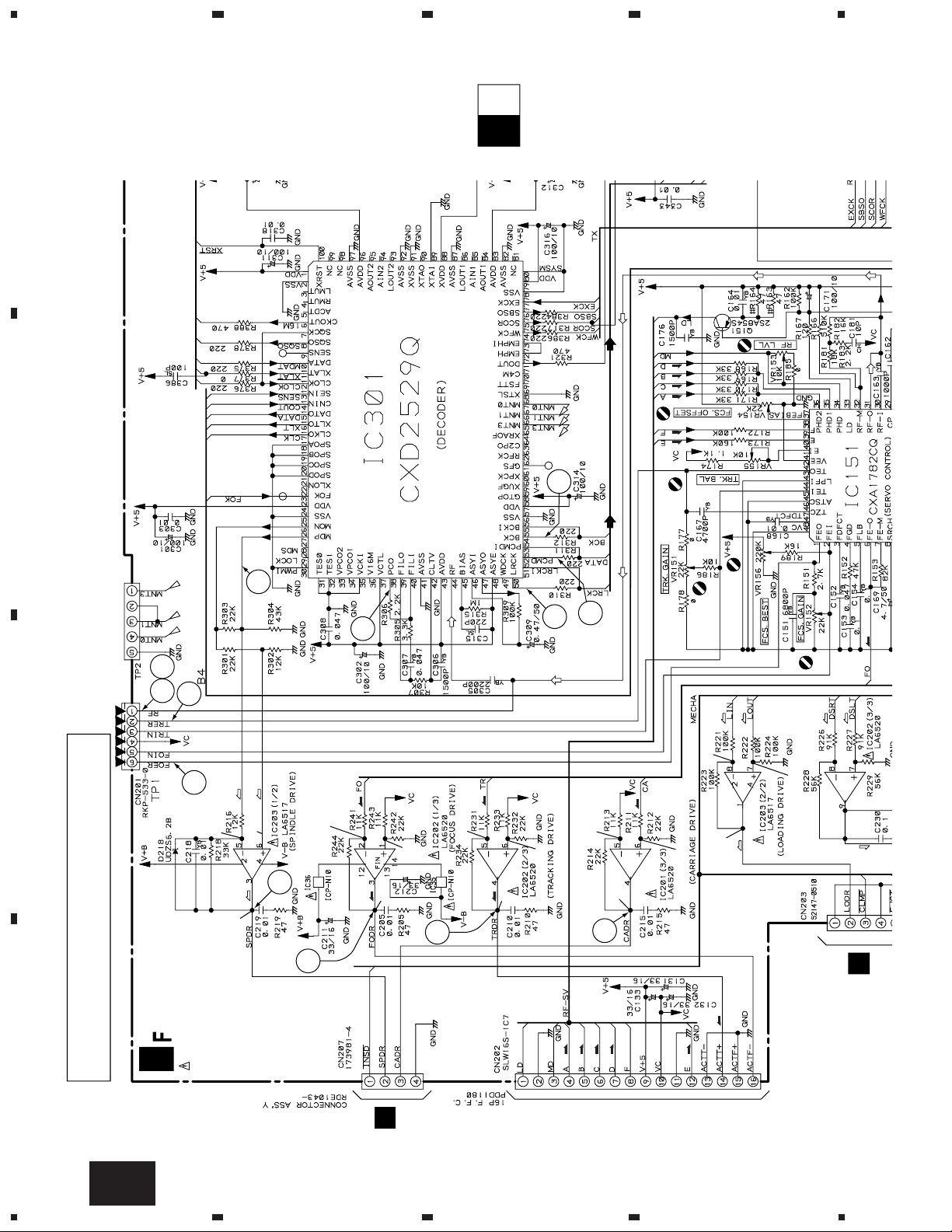
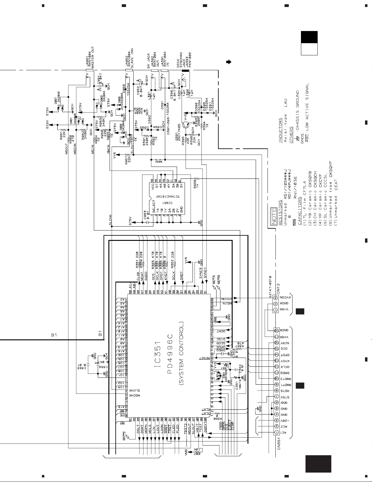
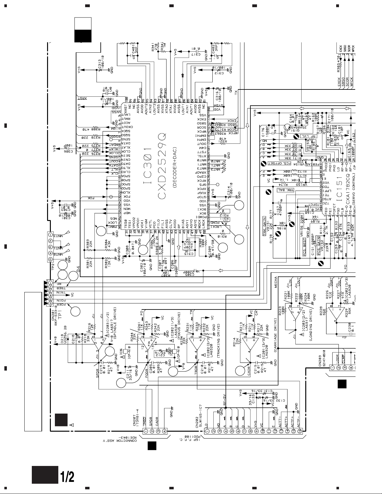
2. SCHEMATIC DIAGRAM
2.1 MAIN BOARD ASSY
A
B
234
C
D
6
K-a
1234
F

5
B
J631
J
J601
F
J651
D
J1601
J11
J701
0V
0V
0V
2SD2144S
L
F
O
F
SIGNAL ROUTE
: AUDIO SIGNAL
: EFM SIGNAL
: FOCUS SERVO LOOP
: TRACKING SERVO LOOP
: CARRIAGE SERVO LOOP
: SPINDLE DRIVE
: LOADING DRIVE
: DOOR DRIVE
: SELECT DRIVE
(S)
(C)
(T)
(F)
(D)
(SEL)
(L)
(SEL)
(SEL)
(SEL)
(D)
(D)
(D)
(F)
(T)
(C)
23
K-b
K-a
67
NOTE: When ordering service parts, be sure to refer to “PARTS
LIST of EXPLODED VIEWS” or “PCB PARTS LIST”.
8
PD-F19
A
B
C
5
6
D
K-a
7
8
F
7

A
K-bK-a
B
1
PD-F19
MAIN
K
BOARD
ASSY
(PWZ3826)
COAXIAL
DIGITAL OUT
234
N
J501
C
D
8
K-b
TO IC301(CXD2529Q)
TO IC151(P22)
F
1234
5
K-bK-a
67
8
PD-F19
SIGNAL ROUTE
: AUDIO SIGNAL ROUTE
A
B
Metal film
J71
F
O
CN701
F
L
C
D
TO CN11
HLEM18S–1
TO BUS MECHA
5
6
TO BUS MECHA
K-b
7
8
F
9

1
234
PD-F19
2.2 DISPLAY BOARD ASSY, POWER BOARD ASSY and KEY BOARD ASSY
A
K
CN351
F
DISPLAY BOARD ASSY
L
B
(PWZ3840)
DISPLAY BOARD ASSY
S701 : MODE
S702 : CLEAR
S703 : PROGRAM
S704 : RANDOM
S705 : TIME/CHARA
S706 : POWER
S707 : SINGLE LOADER ACCESS
S708 : SINGLE LOADER PLAY
J801
Q
C
M
J701
D
10
L F
1234

1
23
4
PD-F19
K
CN11
K
CN12
A
O
POWER BOARD ASSY
(PWZ3855)
F
LIVE
F
HEAT SINK:
NEUTRAL
To AC POWER CORD
B
KEY BOARD ASSY
Q
(PWZ3836)
L
F
CN702
C
D
O F
1
2
3
Q
4
11
1
234
PD-F19
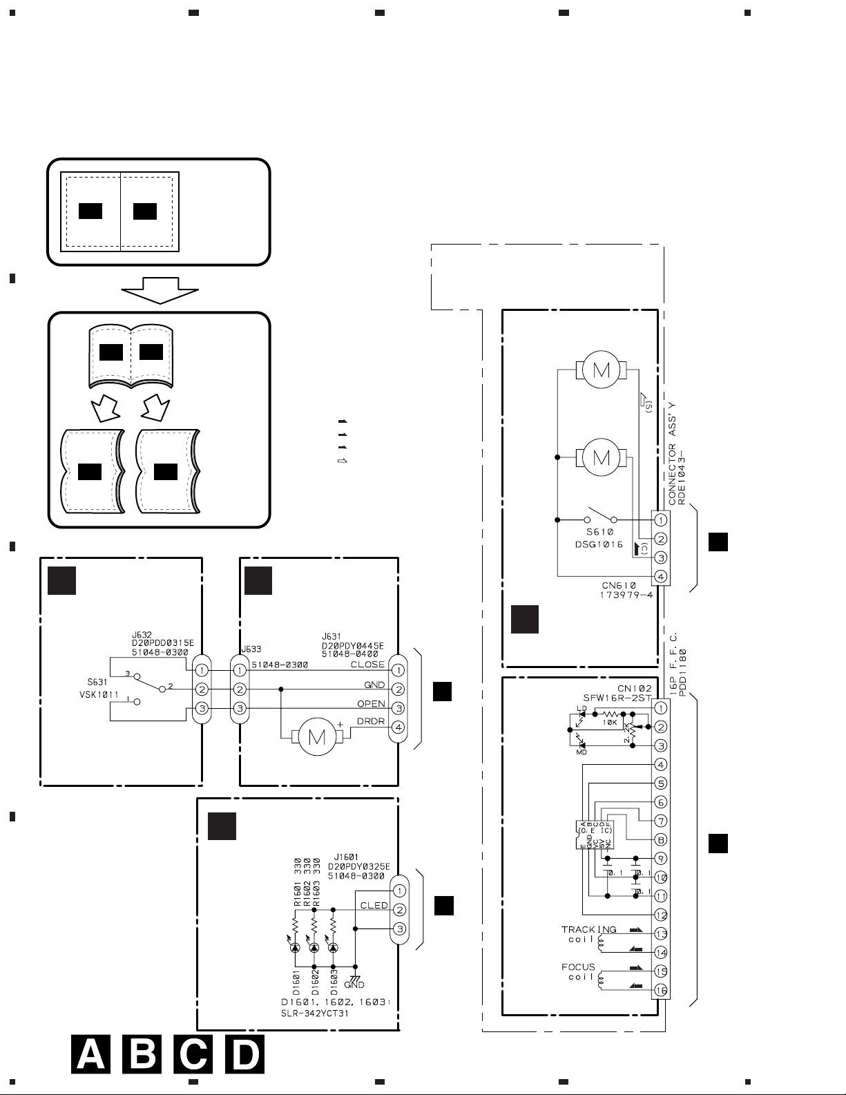
3. PCB CONNECTION DIAGRAM
A
NOTE FOR PCB DIAGRAMS:
1. Part numbers in PCB diagrams match those in the schematic
diagrams.
2. A comparison between the main parts of PCB and schematic
diagrams is shown below.
Symbol in PCB
Diagrams
BCE
BCE
Symbol in Schematic
Diagrams
BCE
BCE
BCEBCE
Part Name
Transistor
Transistor
with resistor
B
Symbol in PCB
Diagrams
DGS
Symbol in Schematic
Diagrams
DGSDGS
Part Name
Field effect
transistor
Resistor array
3-terminal
regulator
3. The parts mounted on this PCB include all necessary parts
for several destination.
For further information for respective destinations, be sure
to check with the schematic diagram.
4. Viewpoint of PCB diagrams
P. C. Board Chip Part
CapacitorConnector
SIDE A
SIDE B
Q
KEY BOARD ASSY
SIDE A
L
CN702
C
Q
KEY BOARD ASSY
SIDE B
(PNP1450-A)
D
12
Q
1234

FILE-TYPE CD PLAYER
PD-F1007
THIS MANUAL IS APPLICABLE TO THE FOLLOWING MODEL(S) AND TYPE(S).
ORDER NO.
RRV2001
Type
KU AC120V
Model
Power Requirement
PD-F1007
CONTENTS
1. SAFETY INFORMATION.................................... 2
2. EXPLODED VIEWS AND PARTS LIST .............3
3. SCHEMATIC DIAGRAM...................................10
4. PCB CONNECTION DIAGRAM .......................22
5. PCB PARTS LIST.............................................30
6. ADJUSTMENT..................................................34
Remarks
7. GENERAL INFORMATION .............................. 44
7.1 PARTS .......................................................44
7.1.1 IC .......................................................44
7.1.2 DISPLAY ...........................................47
7.2 DIAGNOSIS................................................48
7.2.1 DISASSEMBLY .................................48
7.2.2 ERROR CCHECK DISPLAY .............51
7.2.3 EXPLANATION OF DISC
DETECTION......................................52
7.3 BLOCK DIAGRAM......................................54
8. PANEL FACILITIES AND SPECIFICATIONS
.......................................................55
PIONEER ELECTRONIC CORPORATION 4-1, Meguro 1-Chome, Meguro-ku, Tokyo 153-8654, Japan
PIONEER ELECTRONICS SERVICE, INC. P.O. Box 1760, Long Beach, CA 90801-1760, U.S.A.
PIONEER ELECTRONIC (EUROPE) N.V. Haven 1087, Keetberglaan 1, 9120 Melsele, Belgium
PIONEER ELECTRONICS ASIACENTRE PTE. LTD. 501 Orchard Road, #10-00 Wheelock Place, Singapore 238880
PIONEER ELECTRONIC CORPORATION 1998
T–DZE AUG. 1998 Printed in Japan

PD-F1007
1. SAFETY INFORMATION
This service manual is intended for qualified service technicians; it is not meant for the casual
do-it-yourselfer. Qualified technicians have the necessary test equipment and tools, and have been
trained to properly and safely repair complex products such as those covered by this manual.
Improperly performed repairs can adversely affect the safety and reliability of the product and may
void the warranty. If you are not qualified to perform the repair of this product properly and safely, you
should not risk trying to do so and refer the repair to a qualified service technician.
WARNING
This product contains lead in solder and certain electrical parts contain chemicals which are known to the state of California to
cause cancer, birth defects or other reproductive harm.
Health & Safety Code Section 25249.6 – Proposition 65
NOTICE
(FOR CANADIAN MODEL ONLY)
Fuse symbols (fast operating fuse) and/or (slow operating fuse) on PCB indicate that replacement parts
must be of identical designation.
REMARQUE
(POUR MODÈLE CANADIEN SEULEMENT)
Les symboles de fusible (fusible de type rapide) et/ou (fusible de type lent) sur CCI indiquent que les
pièces de remplacement doivent avoir la même désignation.
(FOR USA MODEL ONLY)
1. SAFETY PRECAUTIONS
The following check should be performed for the
continued protection of the customer and service
technician.
LEAKAGE CURRENT CHECK
Measure leakage current to a known earth ground
(water pipe, conduit, etc.) by connecting a leakage
current tester such as Simpson Model 229-2 or
equivalent between the earth ground and all exposed
metal parts of the appliance (input/output terminals,
screwheads, metal overlays, control shaft, etc.). Plug
the AC line cord of the appliance directly into a 120V
AC 60 Hz outlet and turn the AC power switch on. Any
current measured must not exceed 0.5 mA.
Reading should
not be above
0.5 mA
Earth ground
Device
under
test
Also test with plug
reversed
(Using AC adapter
plug as required)
Leakage
current
tester
Test all exposed
metal surfaces
AC Leakage Test
ANY MEASUREMENTS NOT WITHIN THE LIMITS
OUTLINED ABOVE ARE INDICATIVE OF A POTENTIAL SHOCK HAZARD AND MUST BE CORRECTED BEFORE RETURNING THE APPLIANCE
TO THE CUSTOMER.
2. PRODUCT SAFETY NOTICE
Many electrical and mechanical parts in the appliance have special safety related characteristics. These
are often not evident from visual inspection nor the
protection afforded by them necessarily can be obtained by using replacement components rated for
voltage, wattage , etc. Replacement parts which have
these special safety characteristics are identified in
this Service Manual.
Electrical components having such features are
identified by marking with a
on the parts list in this Service Manual.
The use of a substitute replacement component which
does not have the same safety characteristics as the
PIONEER recommended replacement one, shown in
the parts list in this Service Manual, may create shock,
fire, or other hazards.
Product Safety is continuously under review and
new instructions are issued from time to time. For
the latest information, always consult the current
PIONEER Service Manual. A subscription to, or additional copies of, PIONEER Service Manual may be
obtained at a nominal charge from PIONEER.
on the schematics and
2

2. EXPLODED VIEWS AND PARTS LIST
NOTES : Parts marked by “ NSP ” are generally unavailable because they are not in our Master Spare Parts List.
The mark found on some component parts indicates the importance of the safety factor of the part.
Therefore, when replacing, be sure to use parts of identical designation.
Screw adjacent to mark on the product are used for disassembly.
2.1 PACKING
7
PD-F1007
9
8
11
10
12
6
1
PACKING PARTS LIST
Mark No. Description Part No.
5
2
4
1 Styrol Protector F PHA1325
2 Styrol Protector R PHA1326
3 Packing Case PHG2316
4 Packing Sheet RHC1023
5 Polyethylene Bag Z21–038
(0.03 × 230 × 340)
6 Operating Instructions (English) PRB1271
7 Remote Control Unit PWW1139
(CD-PD094)
8 Battery Cover AZA7204
NSP 9 Dry Cell Batteries (R6P, AA) VEM–013
10 Control Cable (L=1 m) PDE1247
11 Audio Cable (L=1 m) PDE1248
NSP 12 Warranty Card ARY7023
3
3
PD-F1007
2.2 EXTERIOR (1/2)
19
8
20
14
(1/2)
∗2
22
6
6
C
D
E
21
F
3
15
Refer to " 2.3 EXTERIOR (2/2)".
18
21
G
H
22
20
I
20
A
C
D
23
E
F
G
20
B
H
22
20
2
I
22
13
1
5
Hood Base Assy
16
20
17
20
11 (1/2)
6
20
12
A
10
20
B
20
20
4
11 (2/2)
20
20
7
23
10
20
14
(2/2)
20
9
Refer to " 2.5 FRONT PANEL
ASSY SECTION".
4
20
20
PD-F1007
No. 14: Center Pole
Cut
14 (1/2)
No. 11: Trans Cover
11(1/2)
Cut
14 (2/2)
Cut
11(2/2)
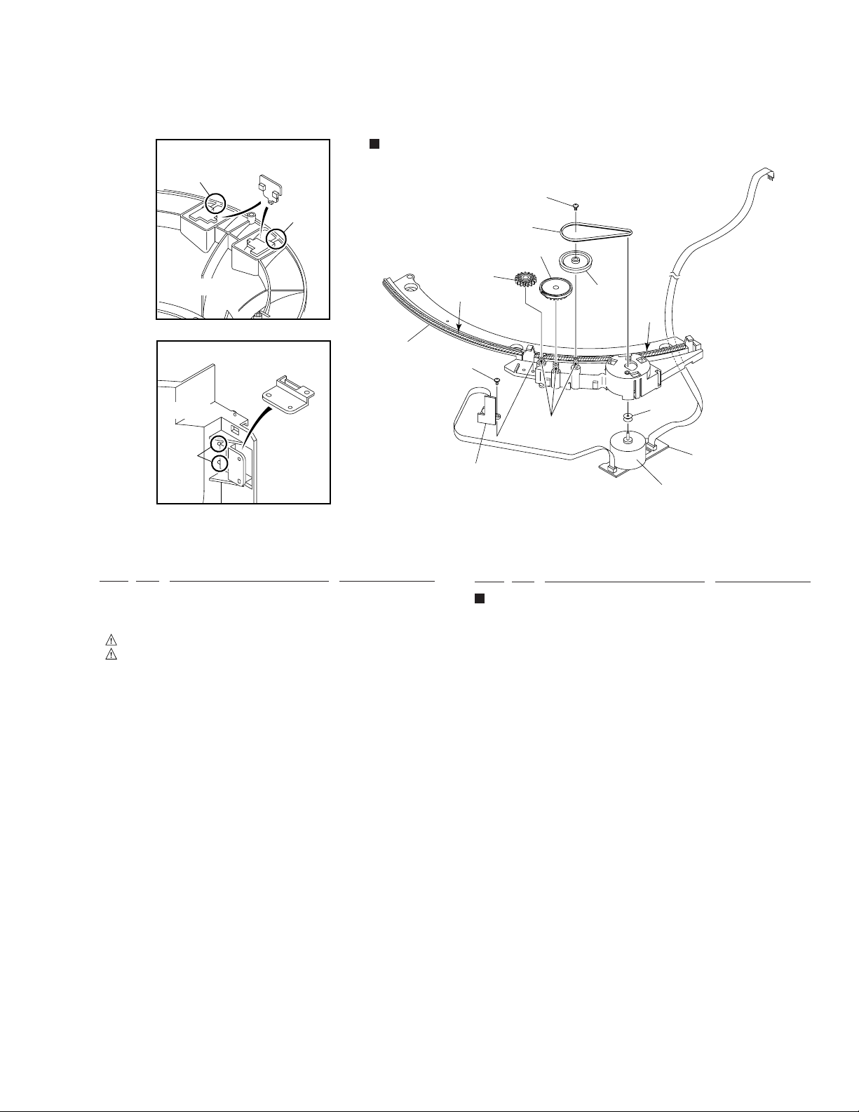
Hood Base Assy Section
EXTERIOR (1/2) PARTS LIST
Mark No. Description Part No.
29
33
26
28
30
∗
2
33
∗
1
25
31
∗
2
27
24
32
Mark No. Description Part No.
1 MAIN BOARD ASSY PWZ3822
2 POWER BOARD ASSY PWZ3852
NSP 3 LED BOARD ASSY PWZ3867
4 Strain Relief CM–22C
5 AC Power Cord VDG1057
6 Screw C PBA1106
NSP 7 Under Base PNA2421
8 Bonnet Case PYY1255
9 Rear Base PNA2424
10 Insulator PNW2766
11 Trans Cover PNW2802
12 Joint PNW2805
13 Cord Clamper RNH–184
14 Center Pole PNW2792
15 CR Lens PNW2816
16 POWER Button PAC1884
17 Hood PNW2793
18 65 Label ORW1069
19 Caution Label PRW1517
20 Screw BBZ30P080FZK
21 Screw FBT40P080FZK
22 Screw IBZ30P080FMC
23 Binder ZCA–SKB90BK
∗2 Ha Narl PN955R (for service) GEM1016
Hood Base Assy Section
NSP 24 DOOR MOTOR BOARD ASSY PWZ3863
NSP 25 DOOR SW BOARD ASSY PWZ3865
26 Belt PEB1300
27 Motor Pulley PNW1634
28 Gear PNW2641
29 Hood Base PNW2791
30 Gear M1 PNW2800
31 Gear Pulley VNL1662
32 Slider Motor VXM1033
33 Screw IPZ20P080FMC
∗1 Froil 397 (for service) GYA1001
∗2 Ha Narl PN955R (for service) GEM1016
5
PD-F1007
2.3 EXTERIOR (2/2)
11
44
52
46
53
52
52
B
40
44
33
44
38
44
52
B
47
44
Refer to " 2.4 FLOAT BASE
ASSY SECTION".
52
20
52
32
∗
1
37
32
21
8
15
28
30
45
44
9
10
35
52
32
32
36
42
∗
1
52
1
7
50
52
6
41
50
51
31
43
5
32
C
∗
∗
1
A
2
19
2
32
∗
1
A
∗
1
C
39
32
∗
1
∗
1
∗
1
34
6

52
23
27
PD-F1007
EXTERIOR (2/2) PARTS LIST
Mark No. Description Part No.
NSP 1 SENSOR BOARD ASSY PWZ3781
NSP 2 SELECT BOARD ASSY PWZ3785
NSP 3 LOADING BOARD ASSY PWZ3788
NSP 4 LOADING SW BOARD ASSY PWZ3790
NSP 5 RADIATE BOARD ASSY PWZ3791
24
[ Apply the Guide R (No. 27) also
∗
2
at the same position.]
22
Note) Tightening Torque: 2 kg·cm
51
9
10
49
4
16
48
a
∗
1
17
NSP 6 RECEIVE BOARD ASSY PWZ3792
25
12
26
NSP 24 L Slider PNW2831
NSP 25 L Arm PNW2832
14
b
29
b
13
a
18
31
43
7 VOLUME BOARD ASSY PWZ3866
8 Clamp Spring ABH7107
9 Loading Belt AEB7029
10 Gear Pulley B ANW7062
11 Roller B ANW7075
12 Arm Spring PBH1225
13 D Arm Spring PBH1226
14 Sheet PED1028
15 Clamper PNW2743
16 Gear 1 PNW2819
17 Gear 2 PNW2820
18 Gear Holder PNW2822
19 Slider Cam PNW2823
20 Clamp Support PNW2826
21 Clamp Holder PNW2827
22 Drive Arm PNW2829
23 Link PNW2830
26 Guide L PNW2833
27 Guide R PNW2834
28 Link L PNW2844
29 Drive Cam PNW2873
30 Lock Plate PNA2438
31 Motor Pulley PNW1634
32 Roller PNW2647
33 Disc Rack PNW2790
34 Rack Base PNW2835
35 ST Gear 0.6 PNW2836
36 ST Gear 1.0 PNW2837
37 Disc Divider PNW2838
38 Guide Support L PNW2839
39 Guide Support R PNW2840
40 Disc Guard PNW2841
41 Sensor Stay PNW2842
42 Guide Roller PNW2843
43 Slider Motor VXM1033
44 Rack Label PAM1770
45 S Label PAM1771
46 +1 Label PRW1507
47 Screw BBZ30P080FZK
48 Screw BMZ26P040FZK
49 Screw BPZ26P060FMC
50 Screw BPZ30P100FCU
51 Screw IPZ20P080FMC
52 Screw PPZ30P080FMC
53 Arm Assy PXA1615
3
∗1 Froil 397 (for service) GYA1001
∗2 Ha Narl PN955R (for service) GEM1016
7

PD-F1007
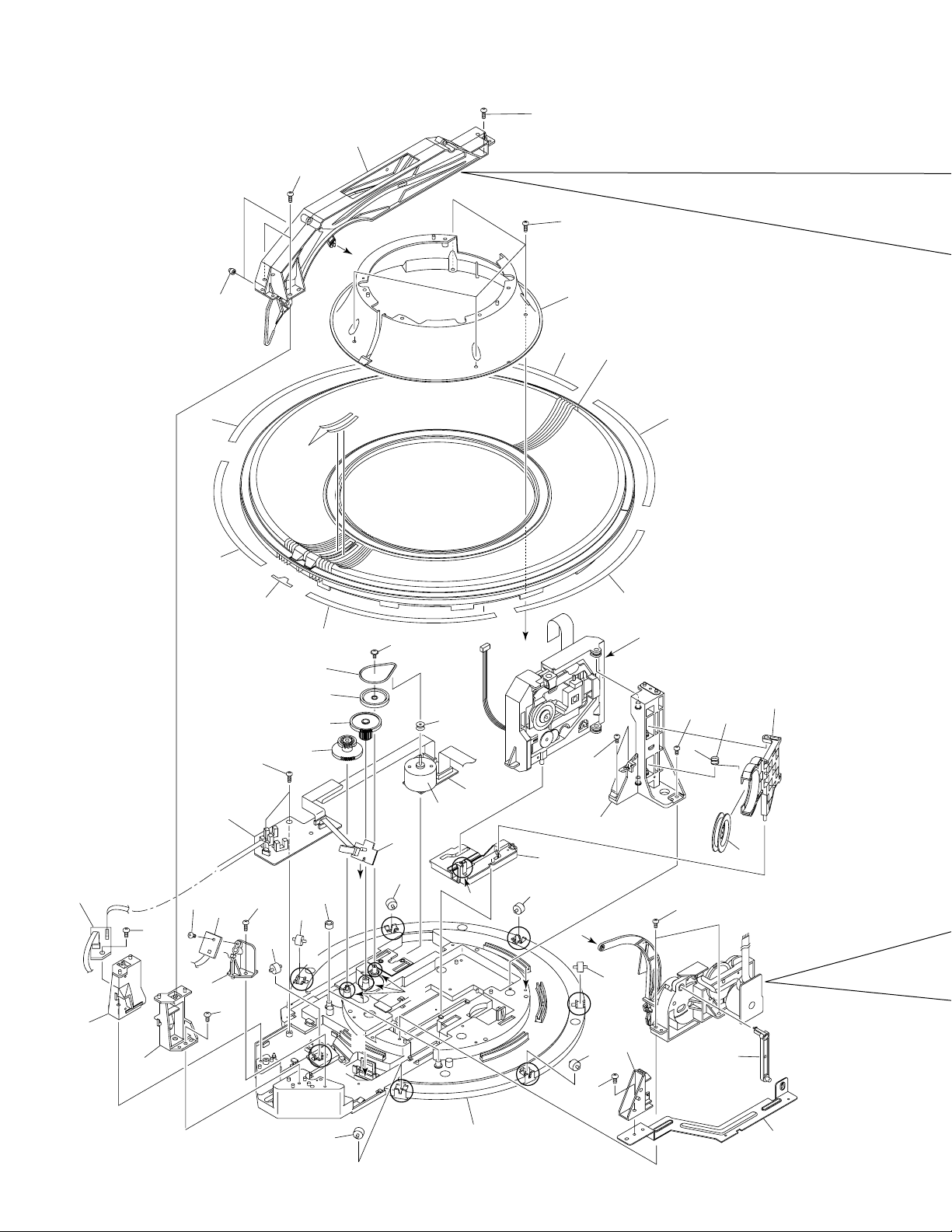
2.4 FLOAT BASE ASSY SECTION
FLOAT BASE ASSY SECTION PARTS LIST
Mark No. Description Part No.
33
32
29
26
31
27
28
29
30
1 Gear 1 PNW2052
2 Gear 2 PNW2053
3 Gear 3 PNW2054
4 Carriage Base PNW2699
5 Pickup Assy - S PEA1335
6 D.C. Motor Assy (SPINDLE) PEA1235
7 Carriage DC Motor Assy PEA1246
8 Pinion Gear PNW2055
9 Carriage DC Motor/0.3W PXM1027
10 Disc Table Assy PEA1314
11 Mechanism Board Assy PWX1192
12 Guide Bar PLA1094
13 …………
14 Screw JFZ17P025FZK
15 Screw JFZ20P040FMC
16 Washer WT12D032D025
17 Clamp Magnet PMF1014
18 Yoke M PNB1312
NSP 19 Disc Table PNW2410
NSP 20 Float Angle ANB7020
21 Gear Stopper PNB1303
22 Screw BPZ20P060FMC
23 Screw BPZ26P100FMC
24 PU Rack Spring ABH7077
25 Rack Holder PNW2056
23
20
12
17
19
10
18
15
5
24
25
16
3
14
2
4
26 Float Base PNW2828
27 Screw ABA7009
28 Float Spring ABH7049
29 Float Rubber AEB7028
30 16P F·F·C/30V PDD1185
NSP 31 Servo Mechanism Assy GM PXA1591
32 Connector Assy (4P) RDE1043
33 Sheet PED1028
How to Install the Disc Table
1
Use nipper or other tool to cut the three sections marked
A
in figure 1. Then remove the spacer
2
While supporting the spindle motor shaft with the
stopper, put spacer on top of the yoke M, and stick the
disc table on top (takes about 9kg pressure). Detach the
21
22
1
6
8
9
7
11
spacer.
1
Spacer
A
Float Base
2
Yoke M
Spacer Setting
Position
A
Carriage Base
Spindle Motor
(Pressure of about 9 kg)
Spacer
Disc Table
1.2mm
Stopper
0.9mm
±0.05mm
6.9mm
8

2.5 FRONT PANEL ASSY SECTION
PD-F1007
4
13
14
19
19
19
19
19
2
6
1
16
9
10
15
5
17
12
7
11
8
FRONT PANEL ASSY SECTION PARTS LIST
Mark No. Description Part No.
1 DISPLAY BOARD ASSY PWZ3839
NSP 2 FUNCTION BOARD ASY PWZ3847
NSP 3 HEADPHONE BOARD ASSY PWZ3860
4 16P F·F·C/30V PDD1189
5 MODE Button PAC1880
6 PLAY Button PAC1881
7 Jog Dial PAC1882
8 ENTER Button PAC1883
9 Name Plate PAM1776
10 Display Window PAM1782
3
18
Mark No. Description Part No.
11 Enter Spring PBH1228
12 Jog Sheet PEC1042
13 FC Cover PNM1323
14 PCB Cover PNM1324
15 LED Lens PNW2019
16 Operation Panel PNW2794
17 Sensor Lens PNW2804
18 Rotary Knob RAC1903
19 Screw PPZ30P100FMC
9
1
23
4
PD-F1007
3. SCHEMATIC DIAGRAM
Note : When ordering service parts, be sure to refer to "EXPLODED VIEWS and PARTS LIST" or "PCB PARTS LIST".
A
3.1 MECHANISM BOARD, DOOR MOTOR BOARD,
A
A
-a
-c
A
A
-b
-d
Large size
SCH diagram
DOOR SW BOARD, LED BOARD and PICKUP
ASSEMBLIES
SERVO MECHANISM ASSY
(PXA1591)
SPINDLE
MOTOR
A
-a
-b
Guide page
Detailed page
A
-b
SIGNAL ROUTE
(F)
: FOCUS SERVO LOOP
(T)
: TRACKING SERVO LOOP
(C)
: CARRIAGE SERVO LOOP
(S)
: SPINDLE DRIVE
A
B
A
-a
ASSY
PEA1235
CARRIADGE
MOTOR
ASSY
PEA1246
K
CN207
DOOR SW
C
BOARD ASSY
(PWZ3865)
DOOR MOTOR
B
BOARD ASSY
(PWZ3863)
MECHANISM
A
BOARD ASSY
(PWX1192)
C
K
CN205
DOOR MOTOR
VXM1033
PICKUP ASSY
(PEA1335)
LED BOARD ASSY
D
(PWZ3867)
K
CN202
K
CN208
D
10
1234
(T)
(T)
(F)
(F)

1
234
PD-F1007
3.2 LOADING SW, LOADING BOARD, SENSOR BOARD, RECIEVE BOARD, RADIATE
BOARD and SELECT BOARD ASSEMBLIES
LOADING
F
BOARD
ASSY
(PWZ3788)
LOADING SW ASSY
E
(PWZ3790)
REAF SW
VSK1011
LOADING MOTOR
VXM1033
SENSOR BOARD
G
ASSY
(PWZ3781)
100k
100k
1.5k
150
J605
D20PDY0310E
VOLUME BOARD ASSY
P
(PWZ3866)
22k
VR601
CN605 CN604
52147–0310 ×2
J604
D20PDY0315E
I
K
CN203
RADIATE
BOARD
ASSY
(PWZ3791)
RECIEVE
H
BOARD
ASSY
(PWZ3792)
A
B
C
K
CN204
SELECT MOTOR
VXM1033
SELECT
J
BOARD
ASSY
(PWZ3785)
11
1
2
3
4
D

1
PD-F1007
23
4
3.3 MAIN BOARD ASSY
CAUTION : FOR CONTINUED PROTECTION AGAINST RISK OF FIRE,
REPLACE ONLY WITH SAME TYPE NO. ICP-N10, MFD BY
ROHM CO., FOR IC35 AND IC36.
A
K
A
CN610
B
(F)
(F)
(F)
(F)
MAIN
BOARD
ASSY
(PWZ3822)
5
-0.7V
6
8
0V
0V
0.2V
K-a
2 23
3
1.8V
1.8V
(S)
(S)
(S)
7
1.6V
1.6V
1.6V
1.6V
1.7V
(F)
(T)
(C)
(F)
(T)
4
33
53
18
19 16
to PICUP ASSY
(T)
1.7V
(T)
F
0V
(L)
(SEL)
0V
(L)
(L)
0V
(SEL)
(SEL)
(F)
(T)
(F)
(F)
(F)
(F)
(T)
J651
23
SIGNAL ROUTE
C
: AUDIO SIGNAL
: EFM SIGNAL
(F)
: FOCUS SERVO LOOP
(T)
: TRACKING SERVO LOOP
(C)
: CARRIAGE SERVO LOOP
(S)
: SPINDLE DRIVE
(L)
: LOADING DRIVE
(D)
: DOOR DRIVE
(SEL)
: SELECT DRIVE
(T)
0V
0V
(D)
(D)
(D)
0V
(C)
2SD2144S
J
J601
B
D
J631
D
J1601
12
1234
O
J11
L
J701

10
5
678
PD-F1007
K-b
IC301(CXD2529Q) :PLAY MODE
1 2 3 - 4 7 8 9 10 11 12 13 14 16 17 23 24 25
PIN No.
5
Voltage(V)
PIN No.
26 27 38 39 40 41 42 43 44 45 46 47 48 50-55 56 57
Voltage(V)
5
PIN No.
61 71 75 78 79 82 83 87 88 89-9084-86 91-92 93-95 9796 100
Voltage(V)
5
4.7
2.5
3.1 3.12.5 2.5 0.9 2.5 2.5 2.5
2.6-2.7
00505 05 0 505
2.5 2.5 2.5 2.5
4.4 4.7 4.7 4.71.2-1.41.2-1.3
55550 00
0 50
55
0.05
A
N
J501
B
C
D
13
5
6
7
8
PD-F1007
MAIN
BOARD
ASSY
(PWZ3822)
K
F
J651
A
CN610
to PICUP ASSY
1.8V
1.8V
-0.7V
1.6V
1.6V
0V
1.6V
1.6V
0V
1.7V
1.7V
0.2V
0V
0V
0V
CAUTION : FOR CONTINUED PROTECTION AGAINST RISK OF FIRE,
REPLACE ONLY WITH SAME TYPE NO. ICP-N10, MFD BY
ROHM CO., FOR IC35 AND IC36.
(S)
(S)
(S)
(F)
(F)
(F)
(F)
(F)
(F)
(T)
(T)
(T)
(T)
(C)
(L)
(L)
(L)
(SEL)
(SEL)
(SEL)
(F)
(F)
(F)
(F)
(F)
(T)
(T)
7
5
6
8
2 23
4
3
33
53
18
19 16
K-bK-a
A
B
1
23
4
C
D
14
K-a
1234

5
B
J631
J
J601
F
J651
D
J1601
O
J11
L
J701
0V
0V
0V
2SD2144S
SIGNAL ROUTE
: AUDIO SIGNAL
: EFM SIGNAL
: FOCUS SERVO LOOP
: TRACKING SERVO LOOP
: CARRIAGE SERVO LOOP
: SPINDLE DRIVE
: LOADING DRIVE
: DOOR DRIVE
: SELECT DRIVE
(S)
(C)
(T)
(F)
(D)
(SEL)
(L)
(SEL)
(SEL)
(SEL)
(D)
(D)
(D)
(F)
(T)
(C)
23
K-bK-a
678
PD-F1007
A
B
C
5
6
D
K-a
7
8
15

PD-F1007
N
J501
IC301(CXD2529Q) :PLAY MODE
PIN No.
Voltage(V)
PIN No.
Voltage(V)
PIN No.
Voltage(V)
1 2 3 - 4 7 8 9 10 11 12 13 14 16 17 23 24 25
26 27 38 39 40 41 42 43 44 45 46 47 48 50-55 56 57
61 71 75 78 79 82 83 87 88 89-9084-86 91-92 93-95 9796 100
5
5
5
55
55550 00
00 505 05 0 505
0 50
4.7
2.5
2.5 2.5 2.5 2.5
3.1 3.12.5 2.5 0.9 2.5 2.5 2.5
4.4 4.7 4.7 4.71.2-1.41.2-1.3
2.6-2.7
0.05
10
K-bK-a
A
B
1
23
4
C
D
16
K-b
1234

5
K-b
K-a
678
PD-F1007
A
B
C
D
K-b
5
6
7
8
17

PD-F1007
Waveforms
Note: The encircled numbers denote measuring point in the schematic diagram.
TP1-Pin 1: PLAY MODE (RF)
2
500mV/div 500nsec/div
– VC
TP1-Pin 1: TRACK SEARCH MODE
25
(RF)
500 mV/div 200 µsec/div
– VC
TP1-Pin 2: 50T - JUMP (*1) MODE
(TRER)
200mV/div 1msec/div
– VC
IC202-Pin 3: FOCUS-IN (*2) MODE
(FODR)
1V/div 200msec/div
– GND
∗1 50T-JUMP: After switching to the pause mode, press
the manual search key.
∗2 FOCUS-IN: Press the play key without loading a disc.
IC202-Pin 4: 50T - JUMP (*1) MODE
6'4'
(TRDR)
500mV/div 1msec/div
– GND
IC203-Pin 3: PLAY MODE (SPDR)
7
1V/div 50msec/div
– GND
TP1-Pin 6: PLAY MODE (FOER)
3
100mV/div 10msec/div
TP1-Pin 2: PLAY MODE (TRER)
4
200mV/div 1msec/div
– VC
– VC
IC202-Pin 3: PLAY MODE (FODR)
5
1V/div 1msec/div
IC202-Pin 4: PLAY MODE (TRDR)
6
500mV/div 1msec/div
– GND
– GND
IC203-Pin 3: TRACK SEARCH MODE
7
(SPDR)
2V/div 50msec/div
IC202-Pin 9: PLAY MODE (CADR)
8
0.2V/div 2sec/div
– GND
– GND
18
 Loading...