

Pioneer MVH-X580BS, MVH-X580BSXNUC, MVH-X580DAB, MVH-X580DABXNEW5, MVH-X580BT Service Manual
...
PIONEER CORPORATION 28-8, Honkomagome 2-chome, Bunkyo-ku, Tokyo 113-0021, Japan
PIONEER ELECTRONICS (USA) INC. P.O. Box 1760, Long Beach, CA 90801-1760, U.S.A.
PIONEER EUROPE NV Haven 1087, Keetberglaan 1, 9120 Melsele, Belgium
PIONEER ELECTRONICS ASIACENTRE PTE. LTD. 2 Jalan Kilang Barat, #07-01, Singapore 159346
PIONEER CORPORATION 2016
DIGITAL MEDIA RECEIVER
ORDER NO.
CRT5837
MVH-X580BS/XNUC
MVH-X
580BS
MVH-X580DAB/XNEW5
MVH-X580BT/XNEW5
MVH-X585BT/XNES
/XNUC
K-ZZZ MAY 2016 Printed in Japan

1234
1234
C
D
F
A
B
E
SAFETY INFORMATION
CAUTION
Danger of explosion if battery is incorrectly replaced.
Replaced only with the same or equivalent type recommended by the manufacturer.
Discord used batteries according to the manufacturer's instructions.
CAUTION
Where in a manufacturer’s service documentation, for example in circuit diagrams or lists
of components, a symbol is used to indicate that a specific component shall be replaced only
by the component specified in that documentation for safety reasons, the following symbol shall
be used:
This service manual is intended for qualified service technicians; it is not meant for the casual do-it-yourselfer.
Qualified technicians have the necessary test equipment and tools, and have been trained to properly and safely repair
complex products such as those covered by this manual.
Improperly performed repairs can adversely affect the safety and reliability of the product and may void the warranty.
If you are not qualified to perform the repair of this product properly and safely, you should not risk trying to do so
and refer the repair to a qualified service technician.
WARNING
This product may contain a chemical known to the State of California to cause cancer, or birth defects or
other reproductive harm.
Health & Safety Code Section 25249.6 - Proposition 65
2
MVH-X580BS/XNUC

5678
56
7
8
C
D
F
A
B
E
CONTENTS
SAFETY INFORMATION .....................................................................................................................................2
1. SERVICE PRECAUTIONS ................................................................................................................................4
1.1 SAFETY PRECAUTIONS...........................................................................................................................4
1.2 NOTES ON DISASSEMBLY / ASSEMBLY .................................................................................................4
1.3 NOTES ON OPERATION CHECK / DIAGNOSIS.......................................................................................4
1.4 NOTES ON REPLACING PARTS ...............................................................................................................5
1.5 OTHERS.....................................................................................................................................................5
2. SPECIFICATIONS.............................................................................................................................................6
2.1 SPECIFICATIONS ......................................................................................................................................6
2.2 DISC/CONTENT FORMAT .........................................................................................................................6
3. BASIC ITEMS FOR SERVICE ..........................................................................................................................6
3.1 CHECK POINTS AFTER SERVICING .......................................................................................................6
4. BLOCK DIAGRAM ............................................................................................................................................7
4.1 BLOCK DIAGRAM......................................................................................................................................7
4.2 POWER BLOCK DIAGRAM .......................................................................................................................8
5. DIAGNOSIS ......................................................................................................................................................9
5.1 OPERATIONAL FLOWCHART ...................................................................................................................9
5.2 ERROR CODE LIST.................................................................................................................................10
5.3 CONNECTOR FUNCTION DESCRIPTION .............................................................................................12
5.4 FUSE (POLY SWITCH) CHECK...............................................................................................................14
6. SERVICE MODE.............................................................................................................................................15
6.1 DISPLAY TEST MODE 1..........................................................................................................................15
6.2 DISPLAY TEST MODE 2..........................................................................................................................16
6.3 SOFTWARE VERSION UP METHOD......................................................................................................17
7. DISASSEMBLY ...............................................................................................................................................18
8. EACH SETTING AND ADJUSTMENT............................................................................................................20
9. EXPLODED VIEWS AND PARTS LIST ..........................................................................................................21
1 PACKING ..................................................................................................................................................21
9.
9.2 EXTERIOR ...............................................................................................................................................23
10. SCHEMATIC DIAGRAM................................................................................................................................26
10.1 TUNER AMP UNIT (VEHICLE I/F) .........................................................................................................26
10.2 TUNER AMP UNIT (SYSTEM REGULATOR ) .......................................................................................27
10.3 TUNER AMP UNIT (DDCON).................................................................................................................28
10.4 TUNER AMP UNIT (OTHER SUPPLY)...................................................................................................29
10.5 TUNER AMP UNIT (SYSCOM) ..............................................................................................................30
10.6 TUNER AMP UNIT (I/F iPod FLASH MEM)............................................................................................31
10.7 TUNER AMP UNIT (E-VOL(OPAL))........................................................................................................32
10.8 TUNER AMP UNIT (TUNER(LITHIO)) ...................................................................................................33
10.9 TUNER AMP UNIT (HD/DAB MODULE)................................................................................................34
10.10 TUNER AMP UNIT (BT) .......................................................................................................................35
10.11 TUNER AMP UNIT (S11.6 I/F) .............................................................................................................36
10.12 TUNER AMP UNIT (EXTERNAL I/F)....................................................................................................37
10.13 TUNER AMP UNIT (POWER AMP) .....................................................................................................38
10.14 KEYBOARD UNIT ................................................................................................................................39
11. PCB CONNECTION DIAGRAM....................................................................................................................40
11.1 TUNER AMP UNIT .................................................................................................................................40
11.2 KEYBOARD UNIT ..................................................................................................................................42
12. ELECTRICAL PARTS LIST ........................................................................................................................... 43
MVH-X580BS/XNUC
3
1234
1234
C
D
F
A
B
E
1. SERVICE PRECAUTIONS
You should conform to the regulations governing the product (safety, radio and noise, and other regulations), and
should keep the safety during servicing by following the safety instructions described in this manual.
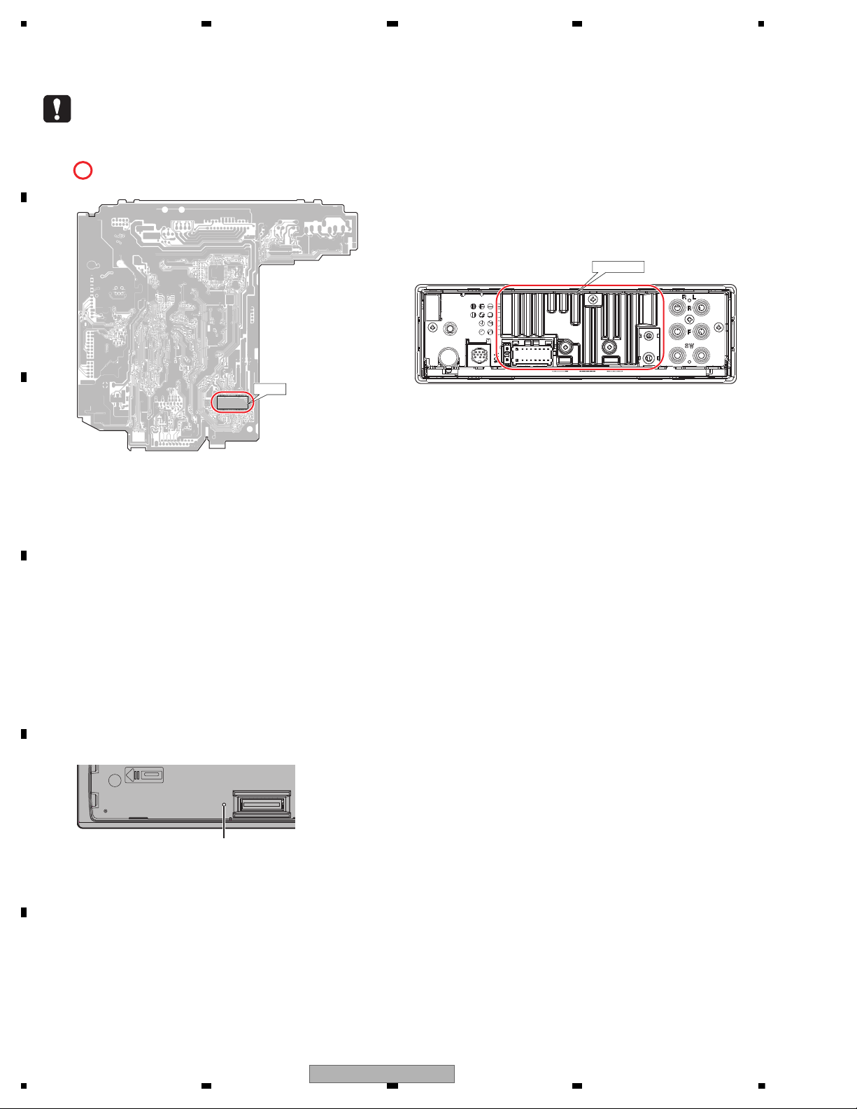
area and a heat sink becomes hot areas. Be careful not to burn yourself.
TUNER AMP UNIT (Side B)
IC201
HEAT SINK
Before disassembling the unit, be sure to turn off the power. Unplugging and plugging the connectors during power-on
mode may damage the ICs inside the unit.
Please be sure to conduct line process to original status if you make assembling after repair.
Resetting the microprocessor
1.Remove the front panel.
2.Press the RESET button with a pointed instrument longer than 8 mm.
RESET button
1.1 SAFETY PRECAUTIONS
1.2 NOTES ON DISASSEMBLY / ASSEMBLY
1.3 NOTES ON OPERATION CHECK / DIAGNOSIS
4
MVH-X580BS/XNUC
5678
56
7
8
C
D
F
A
B
E
Be careful in handling ICs. Some ICs such as MOS type are so fragile that they can be damaged by electrostatic
induction.
Please be careful of not to apply static charge onto integrated circuits, etc, when you conduct repair work.
Especially, please use soldering iron with its tip grounded.
Also, please use a pair of tweezers with static charge protection capability if there is the possibility of contacting to
device terminals, and avoid the use of metal-made tweezers.
The part listed below is difficult to replace as a discrete component part.
When the part listed in the table is defective, replace whole Assy.
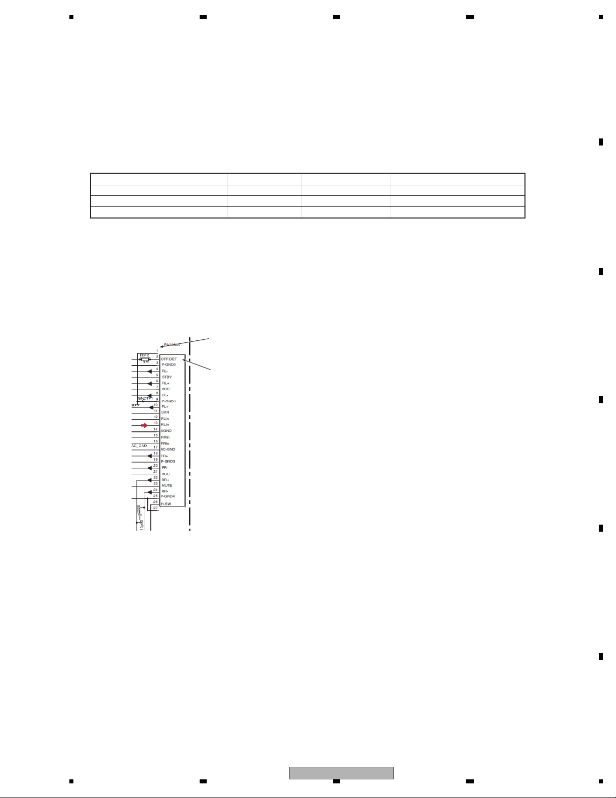
Notes about installation and pin number description of Power IC (IC1301: PA2032A)
The Power IC, PA2032A used on the Tuner Amp Unit is a 25 pin IC.
The same PCB of the Tuner Amp Unit is used for other models that use a 27 pin IC, too.
So, the PCB has lands for a 27 pin IC.
When you replace the Power IC, install the Power IC onto 25 pins (2- 26 pin) located in the center of 27 pins for IC301.
Therefore, when you check the Power IC on the schematic diagram and the PCB connection diagram, you have to pay
attention as follows.
BGA
BGA
Heat pad
Heat pad
IC501
U1001
IC201
IC751
STA1080
CWX4751
BD49101AEFS
PM9015A
SYSTEM MICROCOMPUTER
BT MODULE
SYSTEM POWER SUPPLY
E-VOL
SCHEMATIC DIAGRAM
The pin number of left side is a number
on the PCB (silk printing).
The pin number of right side (in the IC frame)
means the pin number of IC itself.
No conn ection
1
2
3
4
5
6
7
8
9
10
11
12
13
14
15
16
17
18
19
20
21
22
23
24
25
No conn ection
IC1301
For environmental protection, lead-free solder is used on the printed circuit boards mounted in this unit.
Be sure to use lead-free solder and a soldering iron that can meet specifications for use with lead-free solders for
repairs accompanied by reworking of soldering.
Notes on soldering
1.4 NOTES ON REPLACING PARTS
1.5 OTHERS
MVH-X580BS/XNUC
5
1234
1234
C
D
F
A
B
E
2. SPECIFICATIONS
For all items except the backup current, refer to the Owner's Manual.
Backup current......................... 5.0 mA or less
demrifnocebotmetIserudecorP.oN
1 Confirm whether the customer complain has
been solved.
If the customer complain occurs with the
specific media, use it for the operation check.
The customer complain must not be
reappeared.
Display, audio and operations must be
normal.
2 FM/AM tuner Check FM/AM tuner action.
(Seek, Preset)
Switch band to check both FM and AM.
Display, audio and operations must be
normal.
3
receiving it for service.
Item to be checked regarding audio
g
g
Appearance check
No scratches or dirt on its appearance after
2.1 SPECIFICATIONS
2.2 DISC/CONTENT FORMAT
3. BASIC ITEMS FOR SERVICE
3.1 CHECK POINTS AFTER SERVICING
To keep the product quality after servicing, please confirm following check points.
See the table below for the items to be checked regarding audio:
Distortion
Noise
Volume too low
Volume too hi
Volume fluctuatin
Sound interrupted
h
6
MVH-X580BS/XNUC
5678
56
7
8
C
D
F
A
B
E
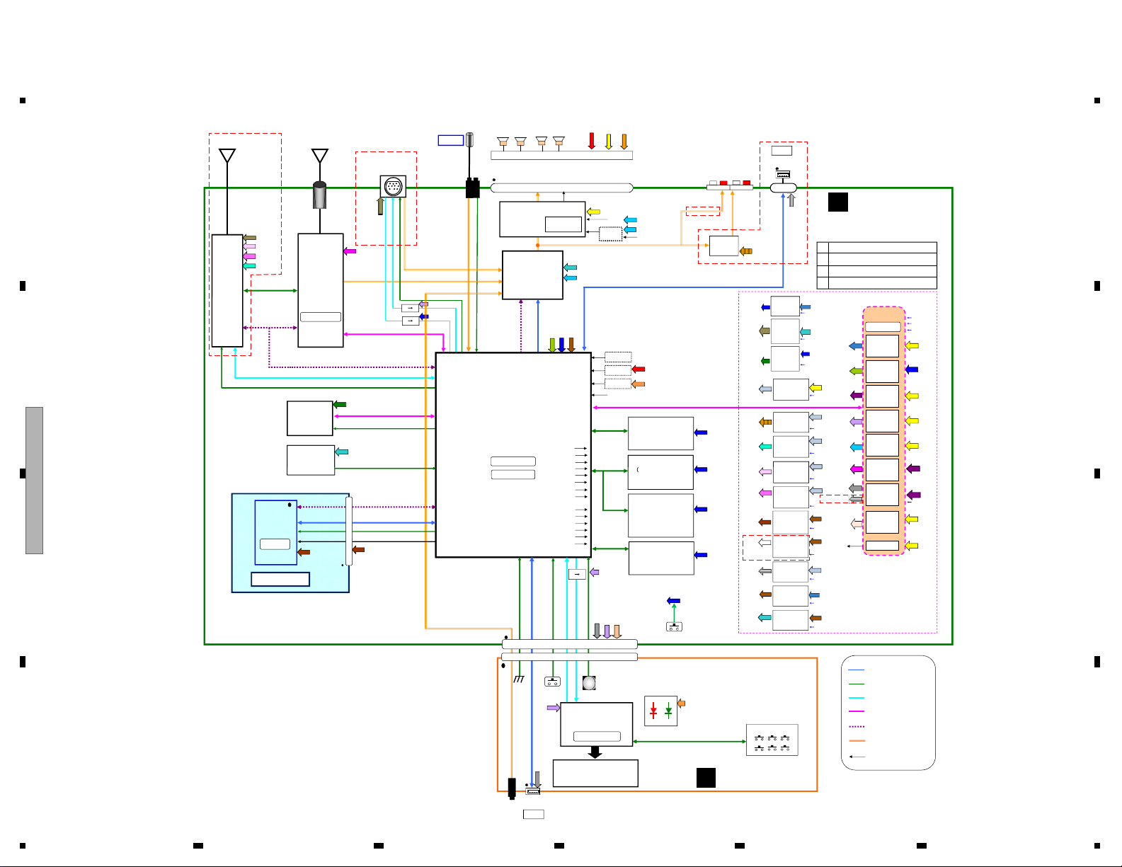
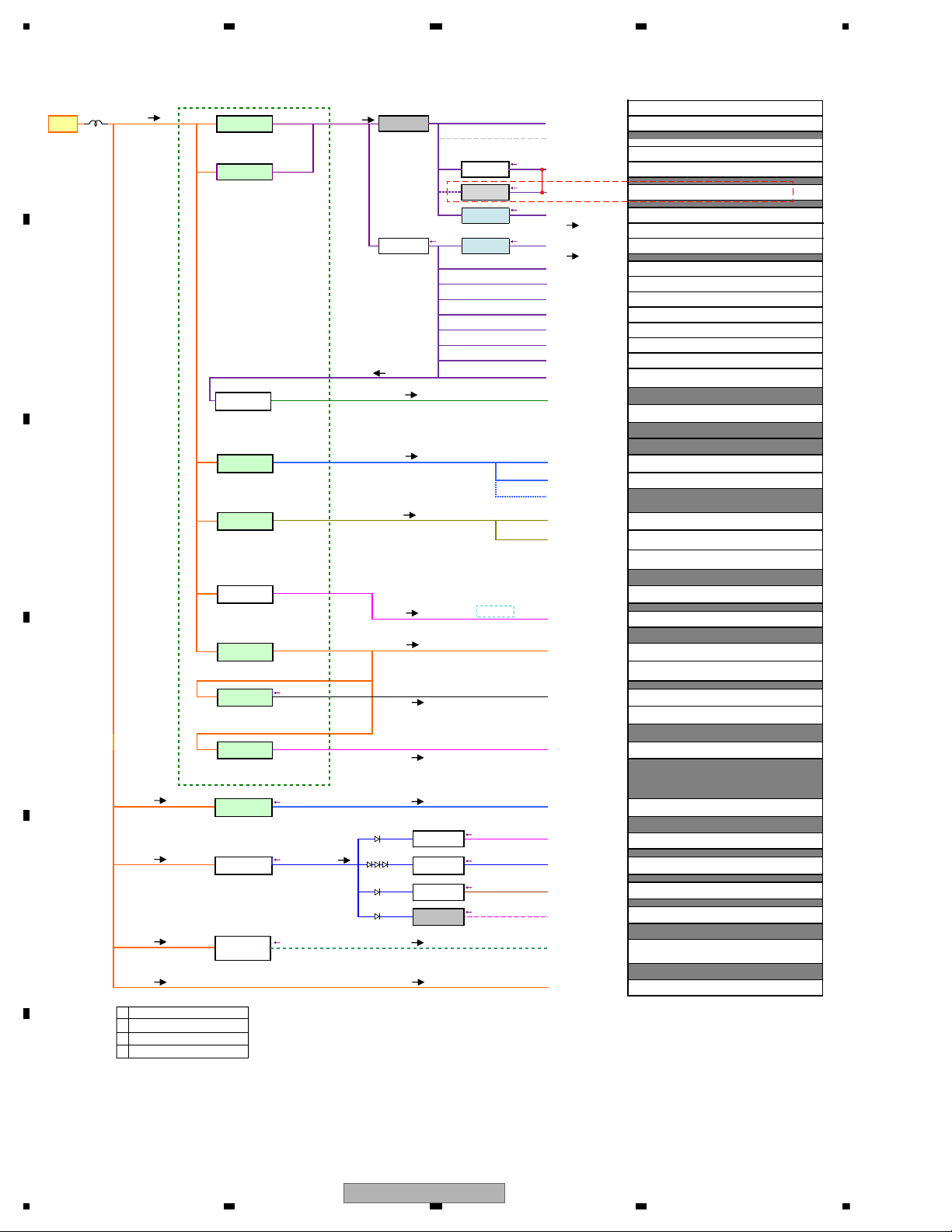
4. BLOCK DIAGRAM
Lithio
TEF6686HN-V102
E.VOL
OPAL
IC751
PM9015A
TUN3.3V
SYS+B5.7V
OPAL_3.3V
MUTE
SYS+B5.7V
MUTE
WIRED REMOTE PREOUT
&
MIC
BT MIC
FM/AM ANT
TUNL TUNR
RL RR
FL
FR
RL
RR
FL FR
STBY
H-SW
B.REM
Power IC
B.Up
JA201 CN1291
Power Connector
B.Up
ACC
1. FL+
2. FR+
3. FL-
4. FR-
5. RL+
6. RR+
7. RL-
8. RR-
9. NC
11. ILM
13. ACC
14. BREM
15. B.UP
16. GND
17. GND
18. B.UP
KEYAD1,KEYAD2
U951
DAB
Module
BTMICIN
ILM
SXI
DIPLAYOUT
SXIL SXIR
AUXL AUXR
DABSXI14V
SXIPW
SXITOSYS
SYSTOSXI
DABSXI14V
D0,D1,CLK,WS
DVCC3.3V
DVCC1.2V
RFVCC3.3V
JA1276
JA1241
JA1231JA851
ILMPW
DIMMER
VDDEN
DD1VON
IC851
EVOL_MCK,EVOL_DATA
EVOL_BCK,EVOL_LRCK
SYSTEM u-com
IC501
STA1080
361pin BGA
ACC
iPod CP
IC701
337S3959
CP_SCL,CP_SDA
CPPW,CPRST
CP_SW3.3V
EEPROM 64KB
(SYS DATA Memory)
IC731
M95512-RMN6P
TUNSCL,TUNSDA
EVOLtoSYS,SYSto,EVOL
EVOL_CS,EVOLCK
USB2_DP,USB2_DM
VDDIO3.3V
VDDIO3.3V
RESET
VDD1.2V
EN
ECO
X851 36.48MHz
X502 24.0MHz
SYNC
VDD_SW 3.3V
VDDEN
VDDIO3.3V
A.SENS
VDD 3.3V
DDC2
STBREG
SWVDD 5V
REG5
VDD1.2
REG1
VDD1.2V
SWVDD5V
SYS5.78V
REG2
SYS+B5.7V
B.Up
TUN3.3V
367.347/439.024kHz
VD 6.0V
DDC1
VD6.0V
VDD3.3V
B.Up
B.Up
B.Up
BD49101AEFS
B.Up
I.SENS
BSENS
RESET IC
IC502
S-80827CNMC-B8M
PW_SCL,PW_SDA
QSPFDBSCK,
QSPCLK,QIO0,
QIO1,QIO2,QIO3,
QSSL
S-Quad Flash 4MB
(
ILM
TELIN
ROMSCK,
ROMCSB
ROMSI,ROMSO
SXIPW
53
35
35
(Stand-by)
DTUNtoSYS,SYStoDTUN
DVCC3 3V
ADI,ADO,
ACLK,AWS
TUNRST
VDDIO_ON3.3V
DAB/SXI_PW
Q401
2SAR502UB
Q201,Q202
SSM3J332R
ANTPW
CP_SW 3.3V
Q701
LSAR523UB
CPPWR
CP_SW3.3V
VDD3.3V
SWVDD5V
DABSXI14V
RFVCC3.3V
IC421
S-1155B33
DD3VON
RFVCC3.3V
DDC5V
IC301
KBD9876EFJ
VDDEN
DDC5V
VDDIO3.3V
VDDIO3.3V
HIOUT8V
IC461
NJW4184DL3
HIOUT_EN
HIOUT8V
IC201
DD3VON
CPPWR
BT18EN
BTPW
EN
ECO
SYNC
USBCTL1
USBCTL2
MUTE
KYDT
DPDT
ROT0,ROT1
USB1_DP,USB1_DM
X501 32.768KHz
TUN3.3V
REG3
USB1_5V
ILM+B
Hiside SW
USB5V
REG4
BSENS
ILMPW
B.Up
B.Up
B.Up
SSENS
AUXL AUXR
BTTOSYS,SYSTOBT,
BTCTS,BTRTS
BTDATAIN,BTDATAOUT
BT_LRCK,BT_BCK
X100
BT MODULE
U1001
CWX4751
BT 3.3V
BT MODULE
BT 3.3V
Q441
2SAR502UB
BT1.8V
IC442
MM3479A18P
BT18EN
BT 3.3V
BT 1.8V
(SYS u-com software)
IC742
MX25L1636EM2I-08G
SDRAM 16MB or 8MB
IC702
M12L128168A-5TG2N
VDDIO3.3V
SWVDD5V
ILM+B
USB1_5V
BT 3.3V
BT_WAKE
DSENS
QSSL2
.
IC422
MM3411A33N
DVCC1.2V
IC423
S-1172B12-E6
DD3VON
DVCC3.3V
DVCC1.2V
USBCTL
/USBCTL2
USB Hiside SW
IC321
BD2232G-G
BT18EN
USB1_5V
USB HisideSW
IC202
BD2232G-G
SWVDD5V
DD1VON
CLK32KOUT
VDDIO3.3V
VDDIO_ON3.3V
USB2_5V
VDDIO3.3V
LCD
LCD Driver
IC1801,IC1802
BU97540KV-M
key matrix
SWVDD5V
SOURCE
USB1_5V
X1801 4.97MHz
Digital Line
CommunicationLine
UART Communicationline
I2S communicationline
Audio Line
Controlline
I2C Communicationline
VBUS
D-
D+
GND
CN1941
1. DGND
2. ILMGND
3. SWVDD
4. ROT1
5. ILM+B
6. ROT0
7. USBGND
8. SDI
9. USBGND
10. SDO
11. USB5V
12. SCK
13. DM
14. SCE
15. DP
16. AUXGND
17. AUXR
18. SOURCE
19. AUXL
20. DSENS
ROTARY
AUX
CN1201
CN1941
ILM+B
RESET
USB1
D-
D+
JA1921 JA1901
BUS
GND
USB2
D-
D+
HIOUT
IC801
NJW1240V
HIOUT8V
VDDEN
USB_CTL1
Q481
EVOL3.3V_SW
LSAR523UB
OPAL_3.3V
HIOUT_EN
IC1301
D
PA2032A
ABC
PAL013B
DAB ANT
S-Quad Flash 2MB/32MB
(DATA Memory)
IC741
QWW4081
QWW4082
QWW4078
4. BLOCK DIAGRM
B
KEYBOARD UNIT
A
TUNER AMP UNIT
A MVH-X580BS/XNUC
B MVH-X580DAB/XNEW5
C MVH-X580BT/XNEW5
D MVH-X585BT/XNES
B
A
D
NM
B
B
BD
B
B
D
A
B
CD
D
D
USB2_5V
ABC
4.1 BLOCK DIAGRAM
MVH-X580BS/XNUC
7
1234
1234
C
D
F
A
B
E
4.2 POWER BLOCK DIAGRAM
B.UP
IC201
L101
BUP14.4V
BD49101AEFS
VDD 3.3V
DDC2
3.15 3.30 3.45
Voltage
1047.6 mA
Current
(
min 1000 mA)
VDD 3.3V
STBREG
(
min 200 mA)
DDC1 : CD
DDC2 : VDD3.3V
LDO1 : VDD1.2V
LDO2 : SYS5.8V
LDO3 : TUN3.3V
LDO4 : USB_H/S_SW
LDO5 : SWVDD5V
VDD 1.2V
REG1
Voltage
1.20 1.25 1.30
Current
330.0 mA
(
min 500 mA)
SYS+B
REG2
5.78
Voltage
95.0 mA
Current
(
min 100mA)
SWVDD
REG5
5.00 5.25 5.50
Voltage
Current
(min 50 mA)
22.0 mA
VDD3.3V
USB HisideSW
BD2232G-G
2.97 3.30 3.63
252.6 mA
121.25 mW
SSM3J332R
2.97 3.30 3.63
795.0 mA
381.60 mW
VDDIO3.3V
VDD1.2V
SYS+B5.7V
SWVDD5V
IC202
Q202
VDDIO_ON3.3V
NM
EVOL3.3V_SW
VDDEN
CPPWER_SW
Q441
BT 3.3V
2SAR502UB
BT 1.8V
MN3411A33
Q481
2SAR502UB
Q701
LSAR523UB
System u-com(Non SWD)
Accordo2
Mecha VDD
BT_ON
BT 3.3V
BT_ON
BT 1.8V
HIOUTEN
E-Volume(Digital)
OPAL_3.3V
CPPWR
i-Pod
CP_SW3.3V
Mecha VDD
System u-con(SWD)
Accordo2
RESET IC
S-FLASH(Quad
S-FLASH(Single 2MB)
EEP-ROM(64KB)
SDRAM(16MB)
5 --> 3 IC
System u-com(SWD)
Accordo2
E-Volume (Analog)
Power Amp (Mute)
Power Amp (STBY)
Grill u-com
3 --> 5 IC
MAX TYP PART NO.
0.1 mA
97.5 mA 65.0 mA
60.0 mA 57.0 mA
67.0 mA PM9015A95.0 mA
7.5 mA
150.0 mA
0.0 mA 0.0 mA S-80827CNMC-B8M
4MB)
17.0 mA
35.0 mA
80.0 mA
717.6 mA
6.0 mA
10.0 mA MX25L1636EM2I-08G
330.0 mA
1047.6 mA
95.0 mA 72.0 mA PM9015A
0.018 mA
10.0 mA
10
.
10.0 mA
3.0 mA
3.0 mA
STA1080
S11.6 STD
BT HIC
BT HIC
337S3959
S11.6 STD171 mA
STA1080
MX25L1636EM2I-08G
M95512-RMN6P2.5 mA
M12L128168A-5TG2N
TC7SH126FU2.0 mA
STA1080
BU97540KV
BU97540KV
TC7SET08FUS12.0 mA
ILM+B SW
Hiside-SW
(
min 500 mA)
Current
220.0 mA
Mecha VD 6.0V
DDC1
Voltage
6.00 V
Current
2 715 mA
REG4
REG3
3.14 3.30 3.47
215.0 mA
6.00 8.00 9.00
20.0 mA
5.00 5.25 5.50
2 450.0 mA
Q401
REG4EN
HIOUTEN
VDDEN
ANTPW
DDC5V
USB LDO
(min 1500 mA)
BUP14.4V
BUP14.4V
BUP14.4V
BUP14.4V BUP14.4V
BD
Voltage
Current
(min 300 mA)
D
NJW4184DL3
Voltage
Current
Voltage
Current
B
DAB ANT PW
TUN 3.3V
IC461
HIOUT8V
IC301
DDC 5V
KBD9876EFJ
SXI PW
ILMPW
VD6.0V
USB1_5V
TUN3.3V
HIOUT8V
DABSXI14V
B
DVCC3.3V
MM3411A33N
B
S-1172B12-E6
B
RFVCC3.3V
S-1172B12-E6
D
USB HisideSW
BD2232G
IC422
IC423
HD1.2V
IC421
IC321
RGB model
DTUN3V_ON
DTUN1V_ON
DTUN1V_ON
USBCTL1
K/B Illumi (RGB)
Mecha VD
USB1/USB2
Si-Tuner
HIOUT
DVCC3.3V
DVCC1.2
RFVCC3.3V
USB1
DAB ANT
SXI PWR
Power Amp
220 mA
1 000.0 mA 300.0 mA
1 500.0 mA 1 000.0 mA
215.0 mA 150.0 mA
2715.0 mA
S11.6 STD
USB1
Lithio
1450.0 mA
20.0 mA 12.0 mA NJW1240V
126 mA 50 mA
383 mA 225 mA
441 mA
1 500 mA 1 000 mA
414 mA
USB1
2 450 mA
400 mA
300 mA 185 mA
A MVH-X580BS/XNUC
B MVH-X580DAB/XNEW5
C MVH-X580BT/XNEW5
D MVH-X585BT/XNES
8
MVH-X580BS/XNUC

5678
56
7
8
C
D
F
A
B
E
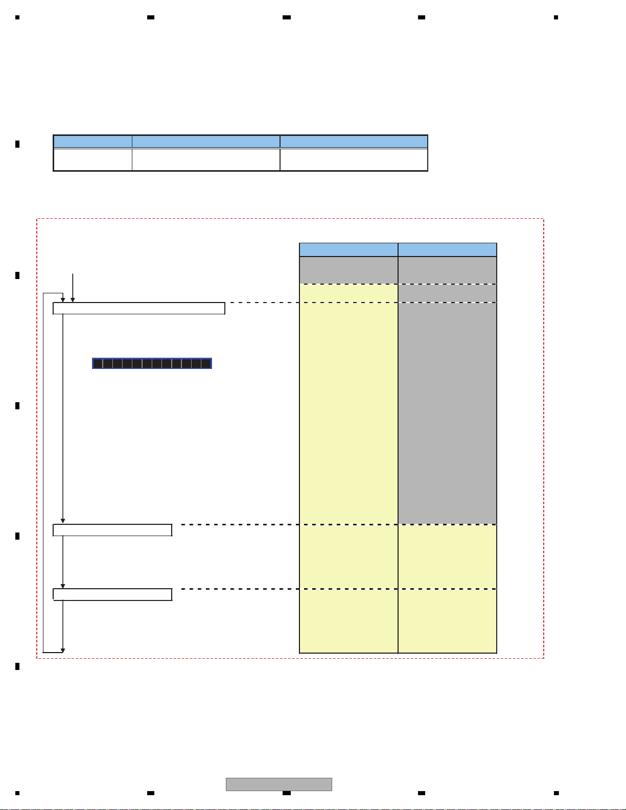
VDDIO_On : Pin E13
Signal on System ucom(IC501)
bsens : Pin A18 or IC201 Pin40
asens : Pin A15
dsens : Pin A17
VDDEN : Pin B15
VDDIO3.3V : Pin E6,E7,E8,F7,F8,M6-M14
VDD1.2V : Pin E9,E10,F6,F9,G5,N5,N6,N10-N13
SWVDD : IC201 Pin1
SYS+B5.7V : IC201 Pin16
VDDIO_On = 3.3V
bsens
asens
dsens
VDD1.2V = 1.2V
VDDIO3.3V = 3.3V
bsens = L
asens = L
Starts
communication
SOC
dsens = L
SWVDD = 5.2V
Source ON
SYS+B5.7V = 5.7V
Completes power-on operation.
(After that, proceed to each source operation)
Power ON
VDDENH
VDDEN = H
Starts
communication
LCD driver
5. DIAGNOSIS
5.1 OPERATIONAL FLOWCHART
MVH-X580BS/XNUC
9
1234
1234
C
D
F
A
B
E
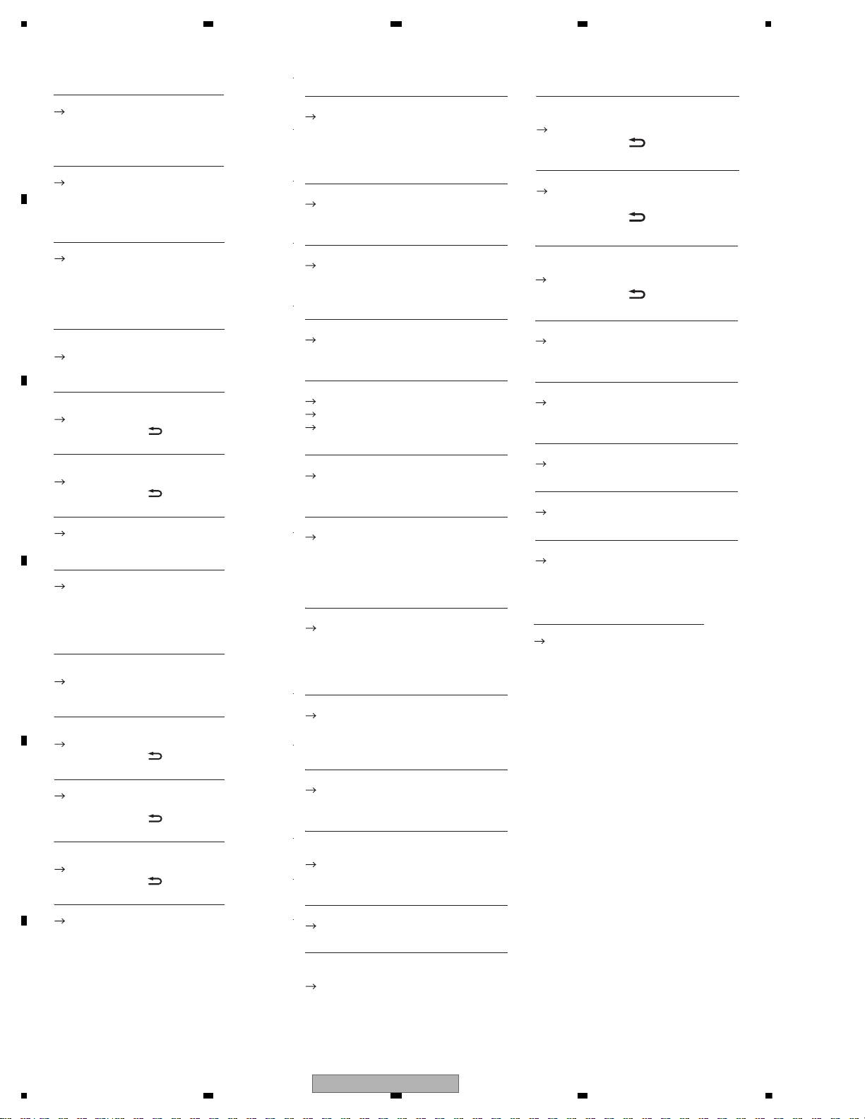
5.2 ERROR CODE LIST
Common
AMP ERROR
This unit fails to operate or the speaker
connection is incorrect.
– Check the speaker connection.
– Check the power IC and its peripheral circuit.
NO XXXX (NO TITLE, for example)
There is no embedded text information.
– Switch the display or play another
track/file.
DAB tuner
ANTENNA ERROR
The antenna connection is incorrect.
– Check the antenna connection.
– Turn the ignition switch OFF and back
to ON again. If the message remains,
contact your dealer or an authorized
Pioneer Service Station for assistance.
Bluetooth device
ERROR-10
The power failed for the Bluetooth
module of the unit.
– Turn the ignition switch OFF and back
to ACC or ON.
Apps
NO BT DEVICE GO TO BT MENU TO
REGISTER
No Bluetooth device found.
– Connect the unit and the device via
Bluetooth.
CONN. FAILED PRESS BAND KEY TO
RETRY
Bluetooth connection failed.
DISCONNECTED PRESS BAND KEY TO
RETRY
Bluetooth connection failed.
CHECK APP
Connection to the application failed.
– Follow the instructions that appear on
the screen.
– Press BAND / to make a
connection again.
– Press BAND / to make a
connection again.
START UP APP
The application has not started running
yet.
–Operate the mobile device to start up
the application.
Spotify
NO BT DEVICE GO TO BT MENU TO
REGISTER
No Bluetooth device found.
– Connect the unit and the device via
Bluetooth.
CONN. FAILED PRESS BAND KEY TO
RETRY
Bluetooth connection failed.
CHECK APP PRESS BAND KEY TO RETRY
Connection to the Spotify application
failed.
DISCONNECTED PRESS BAND KEY TO
RETRY
Bluetooth connection lost.
CHECK APP
Connection to the Spotify application
failed.
– Follow the instructions that appear on
the screen.
–Press BAND/ to make a
connection again.
–Press BAND/ to make a
connection again.
–Press BAND/ to make a
connection again.
Pandora
ERROR-19
Communication failed.
– Disconnect the cable from the device.
Once the device’s main menu is
displayed, reconnect the device and
reset it.
START UP APP
The Pandora application has not started
running yet.
– Start up the Pandora application.
RATING ERROR
The thumb rating operation was
disabled.
– Run the same command for another
track.
CAN'T SKIP
The skip operation was disabled.
– Run the same command for another
track.
TRY LATER
Unable to save thumb rating.
Unable to save BookMark.
Unable to add station.
– Try again later.
MAINTENANCE
Pandora system is undergoing
maintenance.
– Try again later.
SKIP LIMIT
Due to music licensing restrictions,
Pandora limits the total number of skips
per hour.
– Wait until Pandora allows you to skip
again.
UPDATE APP
This version of the Pandora application
is not supported.
– Connect a device that has a
compatible version of the Pandora
application installed.
LOGIN ERROR
Your Pandora account is not logged in.
– Disconnect the cable from the device,
and log in to your Pandora account.
Then reconnect the device.
CHECK DEVICE
Device error message displayed in the
Pandora application.
– Check the connected device.
PLEASE CREATE A STATION ON THE
PHONE
No station found.
– Create a station in the Pandora
application on your connected device.
SELECT STN
No station selected.
– Select a station.
NO BT DEVICE GO TO BT MENU TO
REGISTER
No Bluetooth device found.
– Connect the unit and the device via
Bluetooth.
CONN. FAILED PRESS BAND KEY TO
RETRY
Bluetooth connection failed.
connection again.
CHECK APP PRESS BAND KEY TO RETR
Connection to the Pandora application
failed.
connection again.
–Press BAND / to make a
–Press BAND / to make a
–Press BAND / to make a
DISCONNECTED PRESS BAND KEY TO
RETRY
Bluetooth connection lost.
connection again.
STATION FULL
A new station cannot be added.
– Delete an old station to open a spot
for a new one.
CAN.T DELETE
The station could not be deleted.
– Run the same command for another
station.
NO NETWORK
The connected device is out of area.
–Connect the device to a network.
NO SERVICE IN THIS COUNTRY
The connected device is out of area.
–Connect the device to a network.
STN DELETED
The operation was disabled.
– Run the same command for another
station.
10
MVH-X580BS/XNUC

5678
56
7
8
C
D
F
A
B
E
SiriusXM Satellite Radio
CHECK ANTENNA
The antenna cable may be either
disconnected or damaged.
– Check the antenna connection or
replace if damaged.
CHECK TUNER
The radio is having difficulty
communicating with the SiriusXM
Connect Vehicle Tuner. The tuner may
be disconnected or damaged.
– Verify that the SiriusXM Connect
Vehicle Tuner cable is securely
connected to the radio.
NO SIGNAL
The SiriusXM Connect Vehicle Tuner is
having difficulty receiving the SiriusXM
satellite signal.
– Move your vehicle outdoors with a
clear view of the southern sky.
– Make sure that the SiriusXM magnetic
mount antenna is mounted on a metal
surface on the outside the vehicle.
– Move the SiriusXM antenna away from
any obstructions.
SUBSCRIPTION UPDATED
This unit has detected a change in your
SiriusXM subscription status.
– Press any key to clear the message.
CH UNAVAIL
The channel that you have requested is
not available.
– Check the SiriusXM channel lineup.
CHAN UNSUB
The channel that you have requested is
not included in your SiriusXM
subscription package.
– Check the content of your SiriusXM
subscription package.
CH LOCKED
The channel has been locked by the
Parental Control function.
– Set [LOCKED CH] to [OFF] or [CLEAR
ALL] to [YES] in the FUNCTION settings.
NO TUNEMIX CH
There is only one music in the band.
– Select a band with two or more
channels.
– Add more music channels to the
current band.
MVH-X580BS/XNUC
11
1234
1234
C
D
F
A
B
E
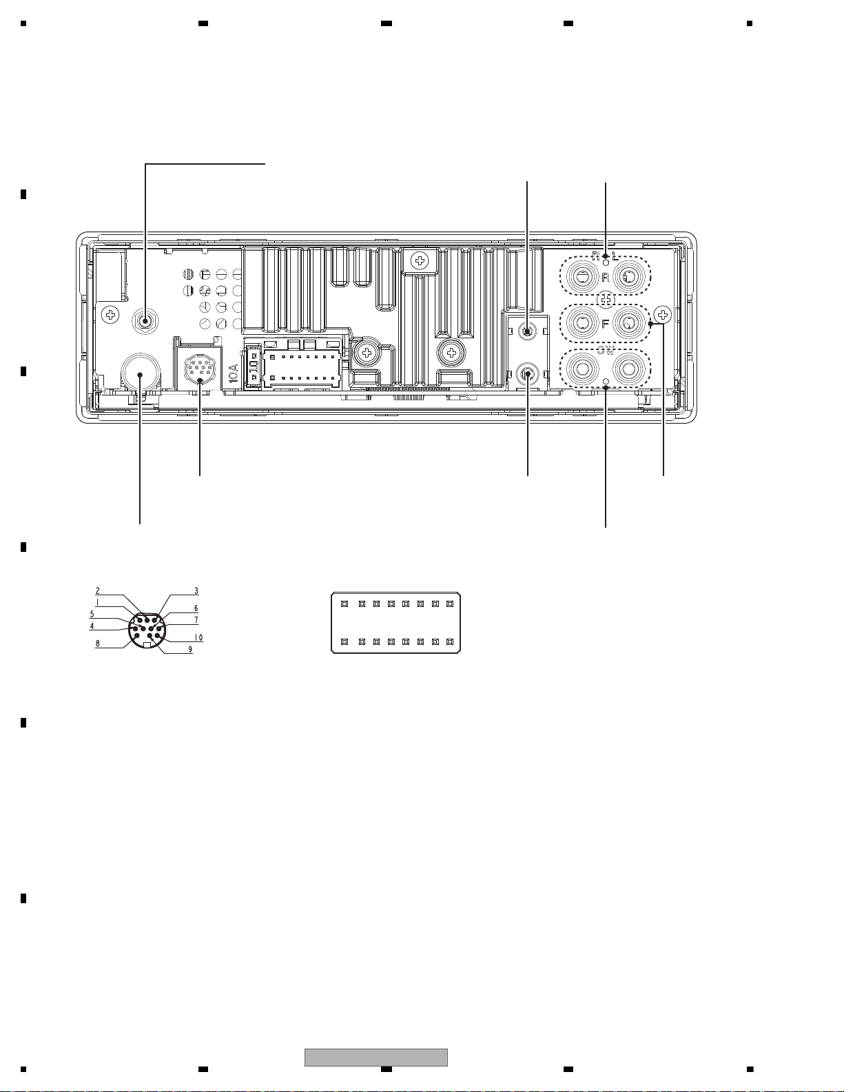
5.3 CONNECTOR FUNCTION DESCRIPTION
1 SXiL
2 SXiTX
3 NC
4 SXiR
5 SXiG
6 SXiRX
7 NC
8 GND
9 SXi PW
10 SXiPW
Sirius XM BUS
FM/AM ANTENNA INPUT
Sirius XM BUS
(MVH-X580BS/XNUC)
WIRED
REMOTE
CONTROL
MICROPHONE
INPUT
SUBWOOFER OUTPUT
FRONT
OUTPUT
REAR
OUTPUT
16
14
12
10 8
6
42
15
13
11
97
5
31
1 FL+
2 FR+
3 FL4 FR5 RL+
6 RR+
7 RL8 RR-
9 NC
10 NC
11 ILL
12 NC
13 ACC
14 B.REM
15 B.UP
16 GND
MVH-X580BS/XNUC
MVH-X580DAB/XNEW5
MVH-X580BT/XNEW5
DAB ANTENNA INPUT
(MVH-X580DAB/XNEW5)
12
MVH-X580BS/XNUC
5678
56
7
8
C
D
F
A
B
E
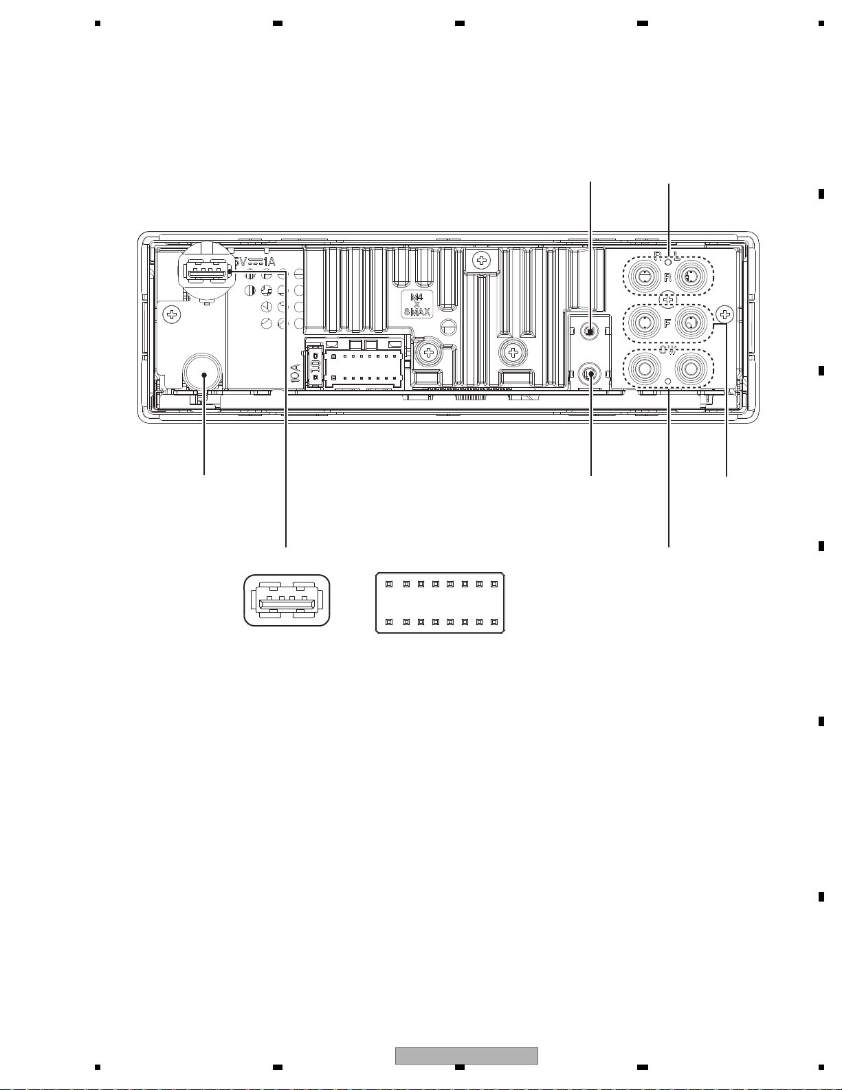
FM/AM ANTENNA
INPUT
WIRED
REMOTE
CONTROL
MICROPHONE
INPUT
SUBWOOFER OUTPUT
FRONT
OUTPUT
REAR
OUTPUT
16
14
12
10 8
6
4
123
15
13
11
97
5
3
214
1 FL+
2 FR+
3 FL4 FR5 RL+
6 RR+
7 RL8 RR-
1 VBUS
2 D−
3 D+
4 GND
9 NC
10 NC
11 ILL
12 NC
13 ACC
14 B.REM
15 B.UP
16 GND
MVH-X585BT/XNES
USB PORT
MVH-X580BS/XNUC
13
1234
1234
C
D
F
A
B
E
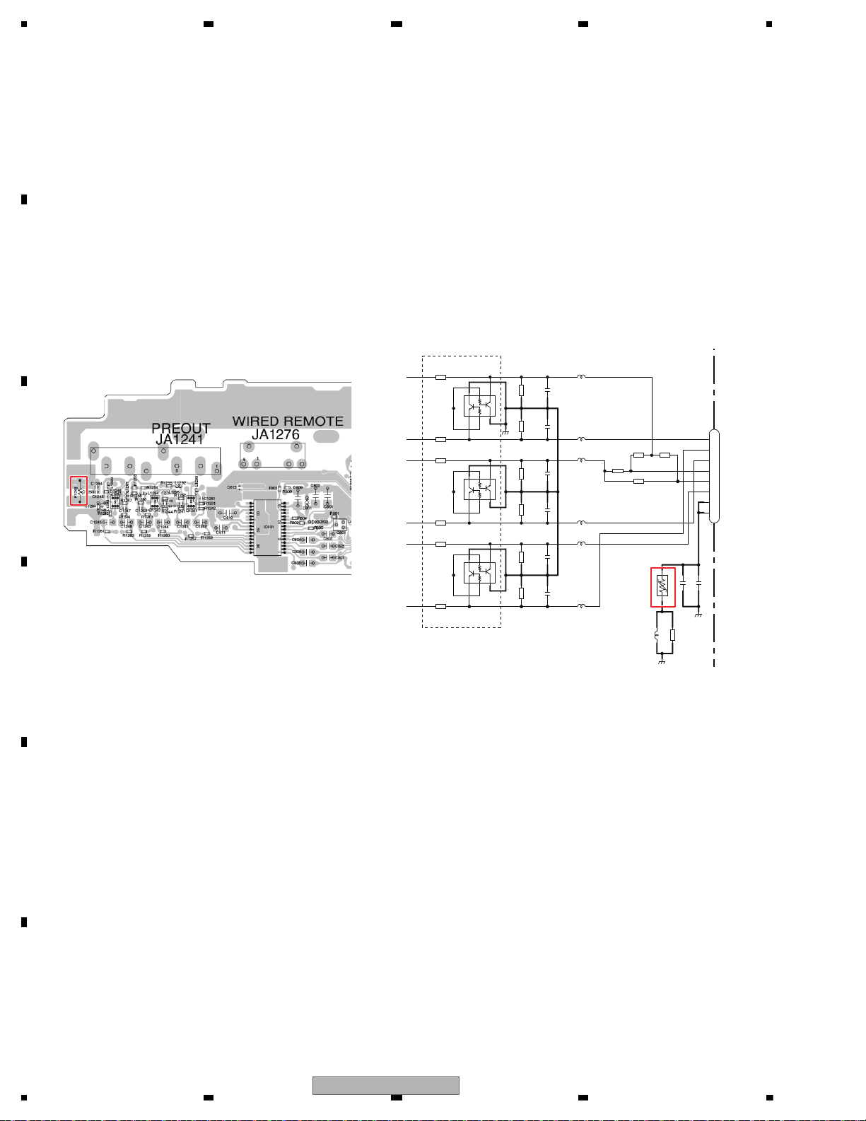
5.4 FUSE (POLY SWITCH) CHECK
*Q1243
1234
5
6
*Q1242
1234
5
6
*Q1241
123 4
5
6
*R1246
C1248
100p/50
R1247
22k
R1248
22k
C1247
100p/50
C1250
100p/50
R1249
22k
R1250
22k
C1249
100p/50
R1252
22k
C1251
100p/50
C1252
100p/50
R1251
22k
GND
GND
*R1243
*R1244
*R1241
*R1242
C1254
0.1u/10
C1253
0.01u/16
*R1245
P1243
FSMD075
12
JA1241
CKB1113
1
2
3
4
5
6
7
8
R1256
NM
R1254
NM
R1255
0
R1253
0
L1292
VTL1126-A
L1293
VTL1126-A
L1294
VTL1126-A
L1296
VTL1126-A
L1297
VTL1126-A
L1295
VTL1126-A
R1284
0
1608
L1298
GND
3P/O
RL
SWR
GND
RR
GND
FL
FR
SWL
2P/O
3P/O
3P/O
A
NM
PREOUT
- No sounds and display output of external unit (the condition when the fuse is blown (poly switch is working))
This product may receive excessive current if the power line connection of the external product is incorrect, such as Ground
connection failure.
The poly switch P1243 on TUNER AMP UNIT is used to protect this product from this excessive current.
Even though poly switch is working to cut the circuit, the sounds of Pre-out output and AUX input are output properly and also
other functions work correctly.
However, you cannot turn on the external product connected to this product as the power is not supplied if the poly switch is
working to cut the circuit.
(The symptom in this case is the sounds of external product are not output on this product when the external product is
connected on a vehicle.)
If you find the symptoms above, check whether or not the poly switch is working to cut the circuit.
If there is any problem (you cannot turn on the power of external unit), check the power connection (Ground) of external unit.
14
MVH-X580BS/XNUC

5678
56
7
8
C
D
F
A
B
E
ROTARY 3
LISTSOURCE
PHONE
Grille condition
Confirmation item Operate LCD ILM
All light up PHONE + LIST States 1 Red
All light off SOURCE States 2 (No light) No light
Button feeling
(and ILM light)
Button 3 States 3 Blue
LCD States
Status 1: All light up. Refer to "Draw 1" below for detail.
States 2: All light off
Status 3: Refer to "Draw 2" below for deference among the models.
Draw 1
Draw 2
Press and hold "PHONE" and "LIST" buttons together, and turn BUP and ACC on.
[How to enter Test mode]
6. SERVICE MODE
6.1 DISPLAY TEST MODE 1
MVH-X580BS/XNUC
15
1234
1234
C
D
F
A
B
E
6.2 DISPLAY TEST MODE 2
* Initial
condition
$ PD number
For Ver.7.01, "701" is displayed
For PEA010A, "010A" is displayed
# System
microcomputer
version
S
$$$$
###
1 + 3
On (state when
entering test mode)
Press and hold "1" and "3" buttons together, and turn BUP and ACC on.
[Operation key]
[How to enter Test mode]
[Test items]
Start display test mode.
Press and hold "1" and "3" buttons together, and turn
BUP and ACC on.
Display is normally updated
Display update is stopped
Product operation is performed as usual, in appearance.
The screen gets still when entering this item.
On (an initial value)
On (lighting condition
of normal times)
On (an initial value or
setting value of default
menu)
On (an initial value or
setting value of default
menu)
On (an initial value or
setting value of default
menu)
Off
All off
All off
All off
Remarks
Key Illumination
Operation key Processing
Icon
Enter display test mode
Switch to next test mode
The information such as the system microcomputer version is checked.
Switching to next display
by pressing “ 1 ” + “ 3 ” buttons together.
Switching to next display
by pressing “ 1 ” + “ 3 ” buttons together.
Switching to next display
by pressing “ 1 ” + “ 3 ” buttons together.
System Version information is displayed.
16
MVH-X580BS/XNUC
 Loading...