

Page 1

RDS MEDIA CENTER RECEIVER
AUTORADIO MULTIMEDIA RDS
RICEVITORE MULTIMEDIALE CON RDS
RECEPTOR CENTRAL MULTIMEDIA RDS
RDS-MULTIMEDIA-EMPFÄNGER
RDS MEDIA CENTER ONTVANGER
ЦИФРОВОЙ МЕДИА-РЕСИВЕР
MVH-8200BT
English
Français Italiano
MVH-8200
Installation Manual
Manuel d’installation
Manuale d’installazione
Manual de instalación
Installationsanleitung
Installatiehandleiding
Руководство по установке
Español
Deutsch
Nederlands
Русский
Page 2

Contents
Connecting the units
Connecting the units ............................ 2
Connecting the power cord ........................... 4
When connecting to
separately sold power amp ....................... 6
Installation ............................................. 7
Installation with the mounting sleeve ........... 7
Removing the unit .......................................... 8
Fastening the front panel ............................... 8
Installing the microphone
(only MVH-8200BT) .................................... 8
When installing the microphone
on the sun visor ............................................. 8
When installing the microphone
on the steering column ................................. 9
Adjusting the microphone angle ........................... 9
WARNING
• To avoid the risk of accident and the potential
violation of applicable laws, no viewing of front
seat video should ever occur while the vehicle is
being driven.
• In some countries or states the viewing of images
on a display inside a vehicle even by persons
other than the driver may be illegal. Where such
regulations apply, they must be obeyed.
CAUTION
• PIONEER does not recommend that you
install or service your display yourself.
Installing or servicing the product may
expose you to risk of electric shock or other
hazards. Refer all installation and servicing
of your display to authorized Pioneer service
personnel.
• Secure all wiring with cable clamps or
electrical tape. Do not allow any bare wiring
to remain exposed.
• Do not drill a hole into the engine
compartment to connect the yellow lead
of the unit to the vehicle battery. Engine
vibration may eventually cause the insulation
to fail at the point where the wire passes from
the passenger compartment into the engine
compartment. Take extra care in securing the
wire at this point.
• Make sure that wires will not interfere with
moving parts of the vehicle, such as the
gearshift, parking brake or seat sliding
mechanism.
• Do not shorten any leads. If you do, the
protection circuit may fail to work properly.
WARNING
LIGHT GREEN LEAD AT POWER CONNECTOR
IS DESIGNED TO DETECT PARKED STATUS
AND MUST BE CONNECTED TO THE POWER
SUPPLY SIDE OF THE PARKING BRAKE SWITCH.
IMPROPER CONNECTION OR USE OF THIS
LEAD MAY VIOLATE APPLICABLE LAW AND MAY
RESULT IN SERIOUS INJURY OR DAMAGE.
2
Page 3

Connecting the units
Note
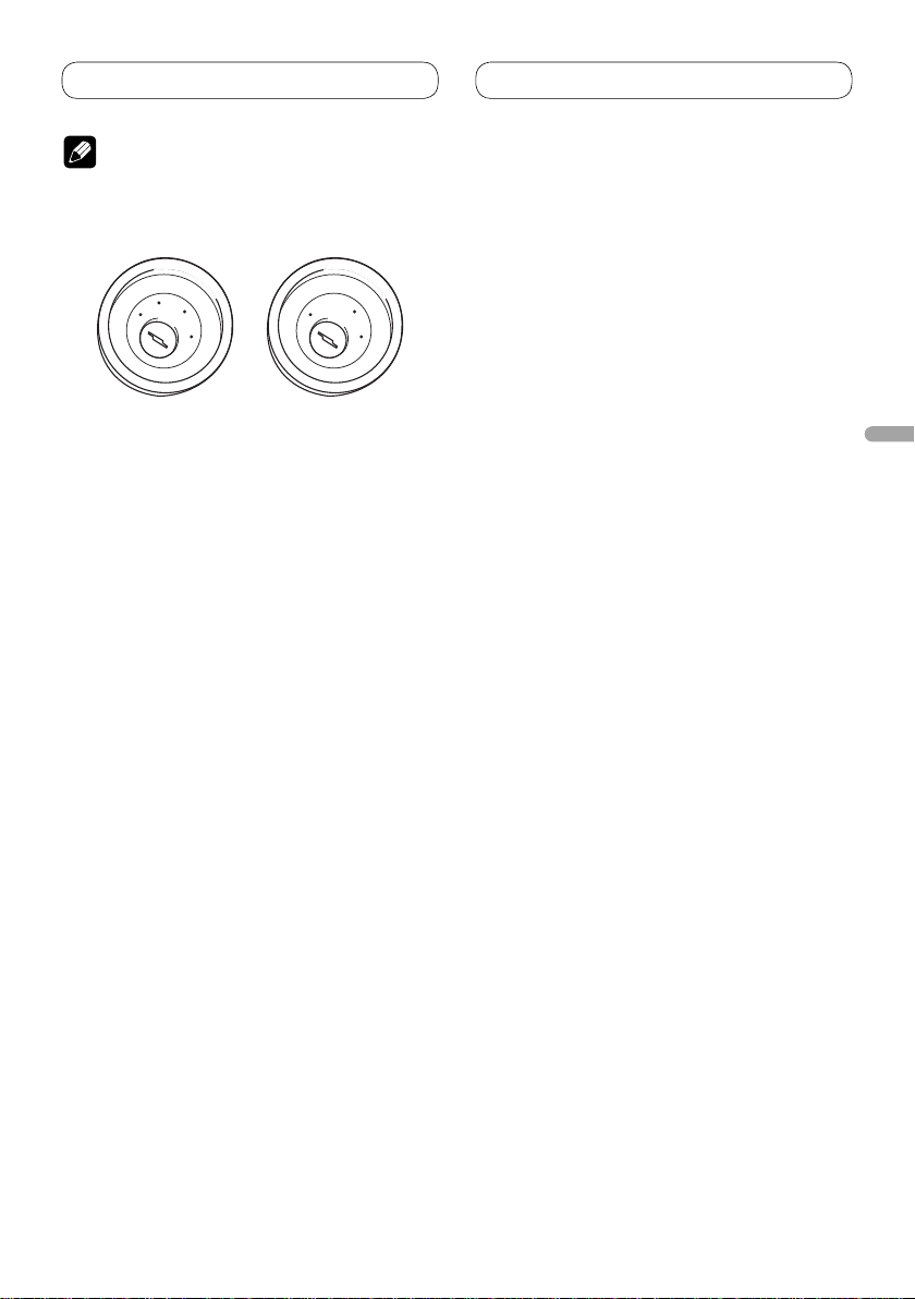
• This unit cannot be installed in a vehicle without
ACC (accessory) position on the ignition switch.
C
C
A
O
F
N
F
O
ACC position
S
T
A
R
T
No ACC position
• Use this unit in other than the following
conditions could result in fire or malfunction.
— Vehicles with a 12-volt battery and negative
grounding.
— Speakers with 50 W (output value) and 4 ohm
to 8 ohm (impedance value).
• To prevent short-circuit, overheating or
malfunction, be sure to follow the directions
below.
— Disconnect the negative terminal of the
battery before installation.
— Secure the wiring with cable clamps or
adhesive tape. To protect the wiring, wrap
adhesive tape around them where they lie
against metal parts.
— Place all cables away from moving parts, such
as gear shift and seat rails.
— Place all cables away from hot places, such as
near the heater outlet.
— Do not pass the yellow cable through a hole
into the engine compartment to connect to a
battery.
— Cover any disconnected cable connectors with
insulating tape.
— Do not shorten any cables.
— Never cut the insulation of the power cable of
this unit in order to share the power to other
equipment. Current capacity of the cable is
limited.
— Use a fuse of the rating prescribed.
— Never wire the speaker negative cable directly
to ground.
— Never band together multiple speaker’s
negative cables.
• Control signal is output through blue/white cable
when this unit is powered on. Connect it to an
external power amp’s system remote control or
the vehicle’s auto-antenna relay control terminal
(max. 300 mA, 12 V DC). If the vehicle is equipped
with a glass antenna, connect it to the antenna
booster power supply terminal.
O
F
N
F
O
S
T
A
R
T
• Never connect blue/white cable to external power
amp’s power terminal. Also, never connect
it to the power terminal of the auto antenna.
Otherwise, battery drain or malfunction may
result.
• Black cable is ground. This cable and other
product’s ground cable (especially, high-current
products such as power amp) must be wired
separately. Otherwise, fire or malfunction may
result if they are accidentally detached.
English
3
Page 4
Connecting the units
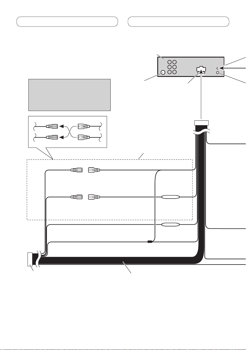
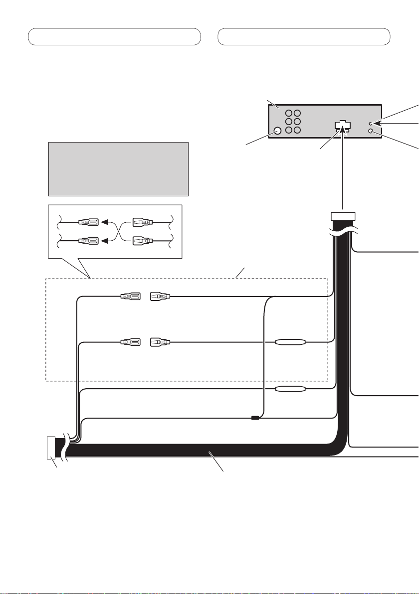
Connecting the power cord
This product
Note:
Depending on the kind of vehicle, the
function of 2* and 4* may be different. In
this case, be sure to connect 1* to 4* and
3* to 2*.
2*
4*
ellow (2*)
Y
Back-up
(or accessor
Red (4*)
Accessory
(or back-up)
Orange/white
Connect to lighting switch terminal.
Black (chassis ground)
Connect to a clean, paint-free metal location.
1*
3*
Yellow (1*)
Connect to the constant 12 V
y)
supply terminal.
Red (3*)
Connect to terminal controlled by
ignition switch (12 V DC).
Antenna input
Connect leads of the same
color to each other.
Fuse resistor
Fuse resistor
Fuse (10 A)
ISO connector
Note:
In some vehicles, the ISO connector may be
divided into two
to both connectors.
. In this case, be sure to connect
4
Speaker leads
White: Front left
White/black: Front left
Gray: Front right
Gray/black: Front right
Green: Rear left or subwoofer
Green/black: Rear left or subwoofer
Violet: Rear right or subwoofer
Violet/black: Rear right or subwoofer
Page 5
Connecting the units
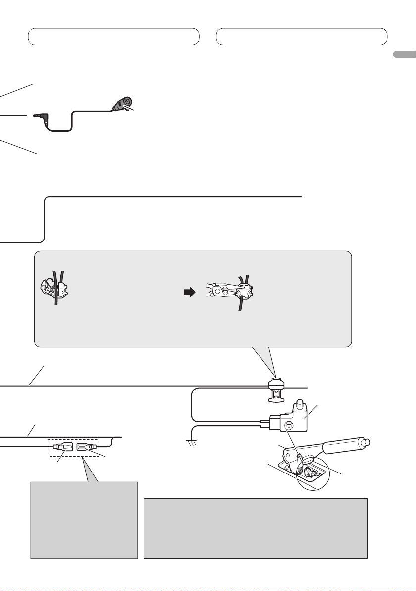
Microphone input
(MVH-8200BT only)
4 m
Wired remote input
Hard-wired remote control
adaptor can be connected (sold
separately).
Microphone
(MVH-8200BT only)
English
Yellow/black
If you use equipment with Mute function
Audio Mute lead on that piece of equipment. If not, keep the
Audio Mute lead free of any connections.
Connection method
1. Clamp the lead.
Note:
· The position of the parking brake switch depends on the vehicle model. For details,
consult the vehicle Owner’s Manual or dealer.
Light green
Used to detect the ON/OFF status of the parking brake. This lead
must be connected to the power supply side of the parking brake
switch.
Blue/white
Connect to system control terminal of the power
amp (max. 300 mA 12 V DC).
Blue/white (6*)
Blue/white (5*)
The pin position of the ISO
connector will differ depending
on the type of vehicle. Connect
5* and 6* when P
antenna control type. In other
types of vehicles, never connect
5* and 6*.
Connect to auto
(max. 300 mA 12 V DC).
in 5 is an
-antenna relay control terminal
Notes:
· Change the initial setting of this unit (refer to the Operation Manual).
The subwoofer output of this unit is monaural.
· When using a subwoofer of 70 W (2 Ω) , be sure to connect with
iolet and V
V
Green and Green/black leads.
ower supply side
P
Ground side
iolet/black leads of this unit. Do not connect anything to
, wire this lead to the
2. Clamp firmly with
needle-nosed pliers.
P
arking brake
switch
5
Page 6
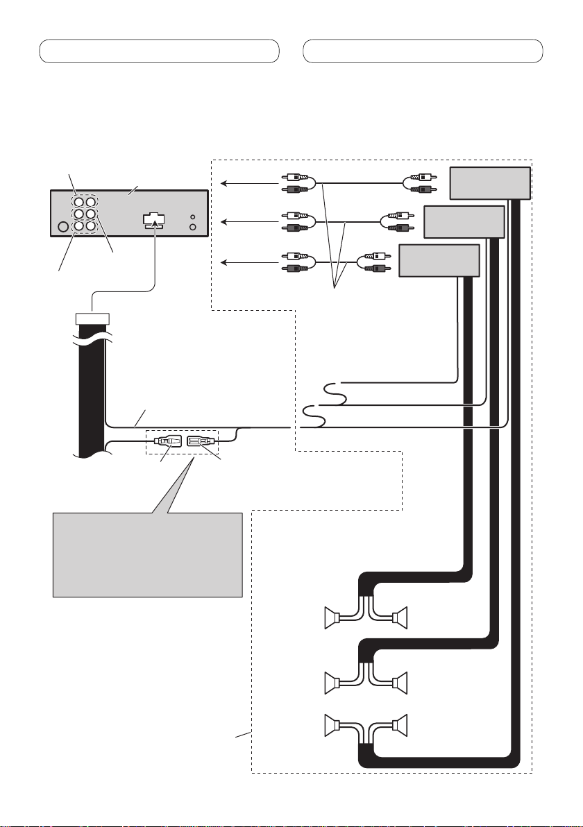
Connecting the units
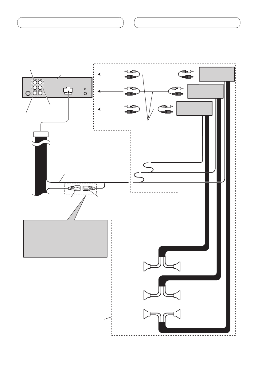
When connecting to separately sold power amp
Rear output
This product
Front output
Subwoofer output
Blue/white
Connect to system control
terminal of the power amp
(max. 300 mA 12 V DC).
Blue/white (5*)
The pin position of the ISO connector will
differ depending on the type of vehicle.
Connect 5* and 6* when Pin 5 is an
antenna control type. In other types of
vehicles, never connect 5* and 6*.
To rear output
To front output
To subwoofer
output
Blue/white (6*)
Connect to auto-antenna
relay control terminal
(max. 300 mA 12 V DC).
Left Right
Power amp
(sold separately)
Power amp
(sold separately)
Power amp
(sold separately)
Connect with RCA cables
(sold separately)
System remote control
Perform these connections when
using the optional amplifier.
Subwoofer
Front speaker Front speaker
Rear speaker
Subwoofer
Rear speaker
6
Page 7

Installation
Note
• Check all connections and systems before final
installation.
• Do not use unauthorized parts. The use of
unauthorized parts may cause malfunctions.
• Consult with your dealer if installation requires
drilling of holes or other modifications of the
vehicle.
• Do not install this unit where:
— it may interfere with operation of the vehicle.
— it may cause injury to a passenger as a result
of a sudden stop.
• Install this unit away from hot places such as near
the heater outlet.
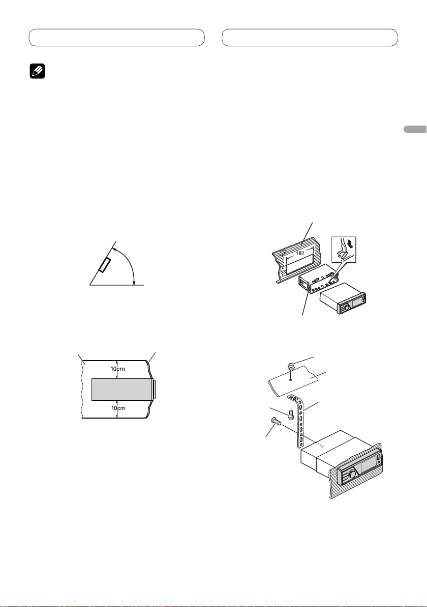
• Optimum performance is obtained when the unit is
installed at an angle of less than 60°.
60°
• When installing, to ensure proper heat dispersal
when using this unit, make sure you leave ample
space behind the rear panel and wrap any loose
cables so they are not blocking the vents.
Leave ample space
Dashboard
Installation with the mounting
English
sleeve
• Use commercially available parts when
installing.
1. Insert the mounting sleeve into the
dashboard.
For installation in shallow spaces, use the
supplied mounting sleeve. If there is enough
space, use the mounting sleeve that came with
the vehicle.
2. Secure the mounting sleeve by using
a screwdriver to bend the metal tabs
(90°) into place.
Dashboard
Mounting sleeve
3. Install the unit as illustrated.
Nut
Firewall or
metal support
Screw
Screw (M4
• Make sure that the unit is installed securely
in place. An unstable installation may cause
skipping or other malfunctions.
×
8)
Metal strap
7
Page 8

Installation
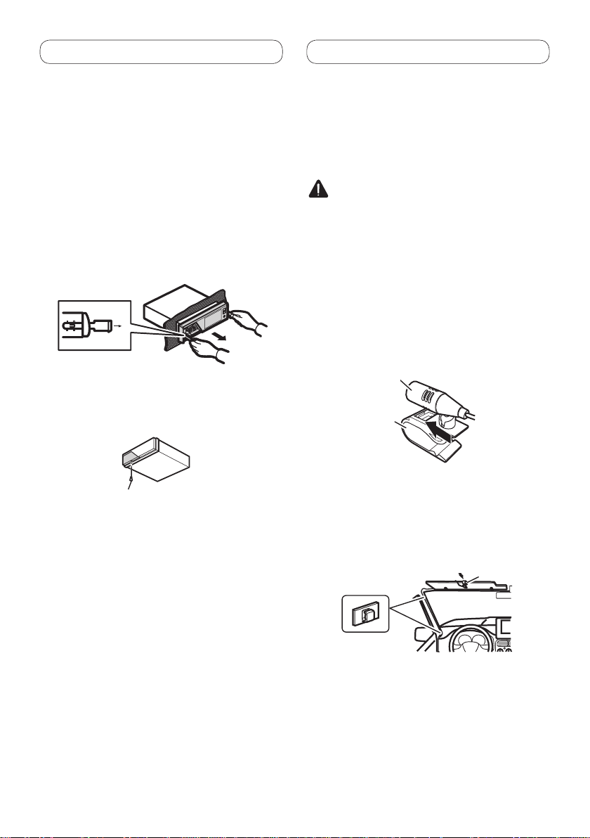
Removing the unit
1. Press the detach button to release the
front panel.
• Refer to the Operation Manual about how to
release the front panel.
2. Insert the supplied extraction keys
into both sides of the unit until they
click into place.
3.
Pull the unit out of the dashboard.
Fastening the front panel
If you do not plan to detach the front panel,
the front panel can be fastened with supplied
screw.
Screw
Installing the microphone
(MVH-8200BT only)
Install the microphone in a position and
orientation that will enable it to pick up the
voice of the person operating the system.
CAUTION
• It is extremely dangerous to allow the microphone
lead to become wound around the steering
column or gearstick. Be sure to install the unit in
such a way that it will not obstruct driving.
When installing the microphone
on the sun visor
1. Install the microphone on the
microphone clip.
Microphone
Microphone clip
2. Install the microphone clip on the sun
visor.
• With the sun visor up, install the microphone
clip. (Lowering the sun visor reduces the voice
recognition rate.)
Microphone clip
Clamp
• Use separately sold clamps to secure the lead
where necessary inside the vehicle.
8
Page 9

Installation
When installing the microphone
on the steering column
1. Install the microphone on the
microphone clip.
Microphone
Microphone base
Microphone clip
Fit the microphone
lead into the
groove
• Microphone can be installed without using
microphone clip. In this case, detach the
microphone base from the microphone clip. To
detach the microphone base from microphone
clip, slide the microphone base.
2. Install the microphone clip on the
steering column.
Double-sided tape
Install the microphone
clip on the rear side of
the steering column.
English
Clamp
• Use separately sold clamps to secure the lead
where necessary inside the vehicle.
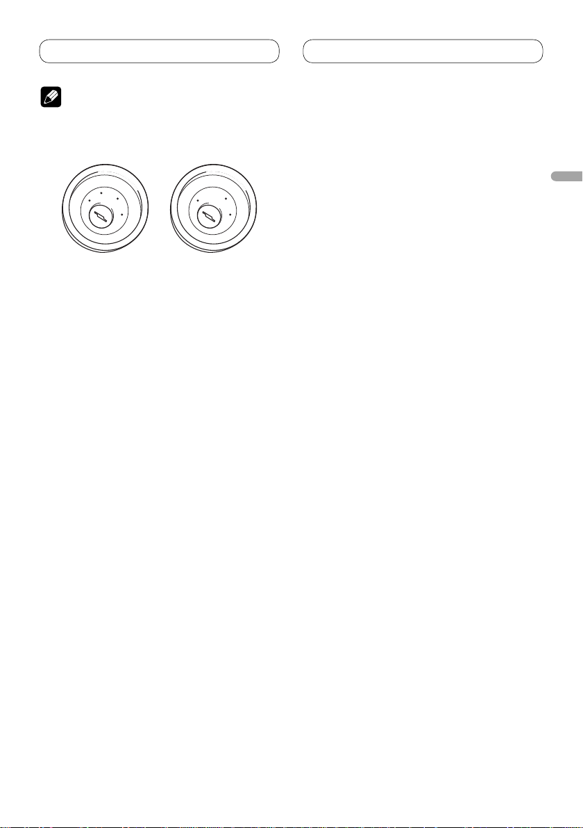
Adjusting the microphone angle
The microphone angle can be adjusted.
9
Page 10

Table des matières
Raccordements des appareils
Raccordements des appareils ............. 2
Branchement du cordon d’alimentation .......4
Raccordements à un amplificateur de
puissance vendu séparément ................... 6
Installation ............................................... 7
Installation avec le manchon de montage .....7
Enlèvement de l’appareil ..................................8
Fixation du panneau avant ...............................8
Installation du microphone
(MVH-8200BT seulement) ...........................8
Installation du microphone sur le pare-soleil .........8
Installation du microphone sur la colonne de
direction............................................................9
Ajustement de l’angle du microphone ....................9
AVERTISSEMENT
• Pour éviter le risque d’accident et une violation
potentielle des lois applicables, l’écran du siège
avant ne doit en aucun cas être regardé pendant
la conduite du véhicule.
• Dans certains états ou pays, il peut être illégal
même pour des personnes autres que le
conducteur de regarder des images sur un
écran à l’intérieur d’un véhicule. Lorsque ces
réglementations s’appliquent, elles doivent être
respectées.
ATTENTION
• PIONEER ne vous recommande pas
d’installer ou d’entretenir vous-même cet
écran, car ces travaux peuvent présenter un
risque d’électrocution ou d’autres dangers.
Confiez tous les travaux d’installation et
d’entretien de votre écran à un personnel de
service Pioneer agréé.
• Immobilisez toutes les câblages avec des
serre-fils ou du ruban isolant. Ne laissez
aucun conducteur à nu.
• Ne forez pas un orifice vers le compartiment
du moteur afin de raccorder le fil jaune de
l’appareil sur la batterie du véhicule car les
vibrations du moteur pourraient à la longue
abîmer l’isolation du fil au point de passage
entre l’habitable et le compartiment du
moteur. Veillez tout particulièrement à bien
immobiliser le fil à ce point.
• Assurez-vous que les câblages ne font pas
obstacle aux pièces mobiles du véhicule,
telles que le levier des vitesses, le frein à
main ou le mécanisme de coulissement des
sièges.
• Ne raccourcissez pas les fils car le circuit
de protection ne fonctionnerait plus
correctement.
AVERTISSEMENT
LE FIL VERT CLAIR SUR LE CONNECTEUR
D’ALIMENTATION A POUR BUT DE DETECTER
L’ETAT DE STATIONNEMENT DU VEHICULE ET
DOIT ETRE CONNECTE AU COTE ALIMENTATION
DU COMMUTATEUR DU FREIN A MAIN. UNE
CONNEXION OU UNE UTILISATION INCORRECTE
DE CE FIL PEUT VIOLER LA LOI APPLICABLE ET
PEUT ENTRAINER DES BLESSURES GRAVES OU
DES DOMMAGES SERIEUX.
2
Page 11
Raccordements des appareils
Remarque
• Cet appareil ne peut pas être installé dans
un véhicule dont le contacteur d’allumage ne
possède pas de position ACC (accessoire).
C
C
A
O
F
N
F
O
Position ACC
S
T
A
R
T
Pas de Position ACC
• Utiliser cet appareil dans d’autres conditions
que les conditions suivantes peut entraîner un
incendie ou un mauvais fonctionnement.
— Véhicule avec une batterie de 12 volts et une
mise à la masse négative.
— Enceintes de 50 W (valeur de sortie) et de 4
ohms à 8 ohms (valeur d’impédance).
• Pour éviter tout court-circuit, surchauffe ou
mauvais fonctionnement, assurez-vous de suivre
les instructions ci-dessous.
— Déconnectez la borne négative de la batterie
avant l’installation.
— Fixez solidement les câbles avec des serre-
câbles ou du ruban adhésif. Pour protéger
le câblage, entourez-le de ruban adhésif à
l’endroit où il est en contact avec des pièces
métalliques.
— Tenez tous les câbles à l’écart des parties
mobiles, telles que le levier de vitesse et les
rails des sièges.
— Tenez tous les câbles à l’écart des endroits
chauds, tels que les sorties du chauffage.
— Ne faites pas passer le câble jaune par un
trou dans le compartiment du moteur pour le
connecter à la batterie.
— Recouvrez tous les câbles non connectés avec
du ruban isolant.
— Ne raccourcissez aucun câble.
— Ne coupez jamais l’isolant du câble
d’alimentation de cet appareil afin partager
l’alimentation avec un autre appareil. La
capacité électrique du câble est limitée.
— Utilisez un fusible de la valeur donnée.
— Ne connectez jamais le câble négatif des
enceintes directement à la masse.
— N’attachez jamais ensemble plusieurs câbles
négatifs de plusieurs enceintes.
O
F
N
F
O
S
T
A
R
T
• Le signal de commande est sorti par le câble
bleu/blanc quand cet appareil est sous
tension. Connectez-le à la télécommande
d’un système d’amplification extérieur ou à la
prise de commande du contrôle de relais de
l’antenne automatique (max. 300 mA, 12 V CC).
Si le véhicule est équipée d’une antenne de
vitre, connectez-la à la prise d’alimentation de
l’amplificateur d’antenne.
• Ne connectez jamais le câble bleu/blanc à la prise
d’alimentation d’un amplificateur extérieur. Et
ne le connectez pas à la prise d’alimentation de
l’antenne automatique. Sinon, la batterie risque
de se décharger ou un mauvais fonctionnement
peut se produire.
• Le câble noir est pour la masse. Ce câble et
les câbles de masse des autres produits (en
particulier les appareils à haute intensité tels
que les amplificateurs) doivent être câblés
séparément. Sinon, ils peuvent entraîner un
incendie ou un mauvais fonctionnement s’ils se
détachent.
Français
3
Page 12
Raccordements des appareils
Méthode de connexion
Bleu/blanc
Connectez à la prise de commande du système de
l’amplificateur de puissance (max. 300 mA 12 V CC).
La position des broches du
connecteur ISO diffère en
fonction du type de véhicule.
Connectez 5* et 6* quand la
broche 5 correspond à la
commande de l’antenne. Dans
les autres cas, ne connectez
jamais 5* et 6*.
Bleu/blanc (5*)
Câbles d’enceinte
Blanc: Avant gauche
Blanc/noir: Avant gauche
Gris: Avant droit
Gris/noir: Avant droit
Vert: Arrière gauche ou caisson de grave
Vert/noir: Arrière gauche ou caisson de grave
Violet: Arrière droit ou caisson de grave
Violet/noir: Arrière droit ou caisson de grave
Connecteur ISO
Remarque:
Dans certains véhicule, le connecteur ISO peut
être divisé en deux. Dans ce cas, assurez-vous
de faire la connexion aux deux connecteurs.
Remarque:
En fonction du type de véhicule, la
fonction de 2* et de 4* peut différer. Dans
ce cas, assurez-vous de connecter 1* à 4*
et 3* à 2*.
1*
3*
2*
4*
Jaune (2*)
Secours
(ou accessoire)
Jaune (1*)
Connectez à une prise
d’alimentation constante 12 V.
Connectez les câbles de la même
couleur les uns aux autres.
Fusible (10 A)
Résistance
fusible
Résistance
fusible
Rouge (4*)
Accessoire
(ou secours)
Orange/blanc
Raccordez ce fil
à
la prise du commutateur d’éclairage.
Rouge (3*)
Connectez à une prise commandée par
le commutateur d’allumage (12 V CC).
Noire (masse au châssis)
Connectez à une section métallique propre et sans peinture.
Cet appareil
Entrée d’antenne
Entrée pour télécommande câblée
Un adaptateur de télécommande
câblée peut être connecté à cette
prise (vendu séparément).
Entrée microphone
(MVH-8200BT seulement)
Branchement du cordon d’alimentation
4
Page 13

Remarques:
·
Change le réglage initial de cet appareil (reportez-vous au mode d’emploi).
La sortie de caisson de grave de cet appareil est monophonique.
· Lors de l’utilisation d’un caisson de grave de 70 W (2 Ω),
assurez-vous de le raccorder aux câbles Violet et Violet/noir de cet
appareil. Ne connectez rien aux câbles Vert et Vert/noir.
Méthode de connexion
1. Serrez le conducteur.
2. Serrez fermement
avec une pince à
mâchoires pointues.
Remarque:
· La position du contacteur de frein à main dépend du modèle de véhicule. Pour les
détails, consultez le manuel de l’utilisateur du véhicule ou un concessionnaire.
Jaune/noir
Si vous utilisez un équipement avec une fonction de mise en
sourdine, raccordez ce conducteur au conducteur de mise en
sourdine audio de cet équipement. Sinon, laissez le
conducteur de mise en sourdine audio non raccordé.
Vert clair
Utilisé pour détecter l’état ON/OFF du frein à main.
Ce fil doit être raccordé sur l’alimentation du
contacteur de frein à main.
Bleu/blanc
Connectez à la prise de commande du système de
l’amplificateur de puissance (max. 300 mA 12 V CC).
Bleu/blanc (6*)
Connectez à la prise du contrôle de relais de
l’antenne automatique (max. 300 mA, 12 V CC).
La position des broches du
connecteur ISO diffère en
fonction du type de véhicule.
Connectez 5* et 6* quand la
broche 5 correspond à la
commande de l’antenne. Dans
les autres cas, ne connectez
jamais 5* et 6*.
Bleu/blanc (5*)
Côté mise à terre
Côté alimentation
Contacteur de
frein à main
4 m
Microphone
(MVH-8200BT seulement)
Entrée pour télécommande câblée
Un adaptateur de télécommande
câblée peut être connecté à cette
prise (vendu séparément).
Entrée microphone
(MVH-8200BT seulement)
Raccordements des appareils
Français
5
Page 14
Raccordements des appareils
Raccordements à un amplificateur de puissance vendu
séparément
Sortie arrière
Cet appareil
Sortie avant
Sortie du caisson
de grave
Bleu/blanc
Connectez à la prise de
commande du système de
l’amplificateur de puissance
(max. 300 mA 12 V CC).
Bleu/blanc (5*)
La position des broches du connecteur
ISO diffère en fonction du type de
véhicule. Connectez 5* et 6* quand la
broche 5 correspond à la commande de
l’antenne. Dans les autres cas, ne
connectez jamais 5* et 6*.
À la sortie
arrière
À la sortie
avant
À la sortie du
caisson de
grave
Bleu/blanc (6*)
Connectez à la prise du contrôle de
relais de l’antenne automatique
(max. 300 mA, 12 V CC).
Raccordez avec des
câbles cinch (RCA)
(vendus séparément)
Télécommande du système
Gauche Droit
Caisson
de grave
Amplificateur de
puissance (vendu
séparément)
Caisson
de grave
Amplificateur de
puissance (vendu
séparément)
Amplificateur de
puissance (vendu
séparément)
Enceinte
avant
Enceinte
arrière
Réalisez ces connexions lors de
l’utilisation de l’amplificateur en
option.
Enceinte
avant
Enceinte
arrière
6
Page 15
Installation
É
Remarque
• Vérifiez toutes les connexions et tous les systèmes
avant l’installation finale.
• N’utilisez aucune pièce non autorisée. L’utilisation
de pièces non autorisées peut causer un mauvais
fonctionnement.
• Consultez votre revendeur si l’installation nécessite
que vous perciez des trous ou effectuiez d’autres
modifications du véhicule.
• N’installez pas l’appareil dans un endroit où:
— il peut gêner la conduite du véhicule.
— il peut causer des blessures à un passager à la
suite d’un arrêt brutal.
• Installez cet appareil à l’écart des endroits chauds
tels que près de la sortie du chauffage.
• Des performances optimales peuvent être obtenues
quand l’appareil est installé avec un angle de moins
de 60°.
60°
• Lors de l’installation de l’appareil, laissez
suffisamment d’espace derrière le panneau arrière
pour permettre une dissipation correcte de la
chaleur et pliez tout câble gênant de façon qu’il
n’obstrue pas les orifices de ventilation.
Laissez suffisamment
d’espace
Tableau de bord
Installation avec le manchon de
montage
• Utilisez des pièces disponibles dans le
commerce lors de l’installation.
1. Insérez le manchon de montage dans
le tableau de bord.
Lors de l’installation de cet appareil dans un
espace peu profond, utilisez le manchon de
montage fourni. Si l’espace est suffisant, utilisez
le manchon de montage fourni avec le véhicule.
2. Fixez le manchon de montage en
utilisant un tournevis pour courber
les pattes métalliques (90°) en place.
Tableau de bord
Manchon de montage
3. Installez l’appareil comme indiqué
sur la figure.
crou
Pare-feu ou support
métallique
Français
Vis
Vis (M4
×
8)
• Assurez-vous que l’appareil est correctement mis
en place. Toute installation instable peut entraîner
des sauts ou autres dysfonctionnements.
Attache en métal
7
Page 16
Installation
Enlèvement de l’appareil
1. Appuyez sur le bouton de
détachement pour détacher le
panneau avant.
• Reportez-vous au mode d’emploi pour savoir
comme retirer le panneau avant.
2. Insérez les clés d’extraction fournies
dans les deux côtés de l’appareil
jusqu’à ce qu’elles s’enclenchent en
place.
3.
Tir
ez l’appareil hors du tableau de
bord.
Fixation du panneau avant
Si vous ne prévoyez pas de détacher le panneau
avant, il peut être fixé avec la vis fournie.
Vis
Installation du microphone
(MVH-8200BT seulement)
Installez et orientez le microphone à un endroit
où il pourra bien capter la voix de la personne
qui commande le système par la voix.
ATTENTION
• Une situation très dangereuse pourrait se
présenter si le fil du microphone devait s’enrouler
autour de la colonne de direction ou du levier de
vitesses. Veillez à cheminer le fil de manière qu’il
ne fasse pas obstacle à la conduite.
Installation du microphone sur
le pare-soleil
1. Fixez le microphone sur l’attache du
microphone.
Microphone
Attache du
microphone
2. Fixez l’attache du microphone sur le
pare-soleil.
• Le pare-soleil étant relevé, fixez l’attache du
microphone. (Le taux de reconnaissance
vocale diminue quand le pare-soleil est
abaissé.)
Serre-fils
Attache du
microphone
• Utilisez des serre-fils vendus séparément pour
fixer le fil conducteur aux endroits nécessaires
dans le véhicule.
8
Page 17

Installation
Installation du microphone sur
la colonne de direction
1. Fixez le microphone sur l’attache du
microphone.
Microphone
Base du
microphone
Attache du
microphone
Cheminez le fil du
microphone dans
la rainure.
• Le microphone peut être installé sans utiliser
l’attache du microphone. Dans ce cas, détachez
la base du microphone de l’attache. Pour
détacher la base du microphone de l’attache,
faites glisser la base du microphone.
2. Fixez l’attache du microphone sur la
colonne de direction.
Bande adhésive
double face
Installez l’attache
du microphone
sur l’arrière de
la colonne de
direction.
Ajustement de l’angle du
microphone
L’angle du microphone peut être ajusté.
Français
Serre-fils
• Utilisez des serre-fils vendus séparément pour
fixer le fil conducteur aux endroits nécessaires
dans le véhicule.
9
Page 18
Indice
Collegamento delle unità
Collegamento delle unità ..................... 2
Collegamento del cavo di alimentazione .......4
Collegamento ad un amplificatore
venduto a parte ...........................................6
Installazione ............................................. 7
Installazione con il supporto di montaggio ....7
Rimozione dell’unità .........................................8
Fissaggio del pannello anteriore .....................8
Installazione del microfono
(solo MVH-8200BT) ......................................8
Quando si installa il microfono sull’aletta
parasole ............................................................8
Quando si installa il microfono sulla colonna
dello sterzo .......................................................9
Regolazione dell’angolo del microfono ...................9
AVVERTENZA
• Per evitare il rischio di incidenti e la potenziale
violazione della normativa applicabile, la visione
dei video dal sedile anteriore è vietata mentre il
veicolo è in movimento.
• In alcuni Stati o Paesi la visione di immagini su un
display installato all’interno di un veicolo, anche
da parte di persone diverse dal conducente,
potrebbe essere illegale. Se sono in vigore
norme di questo tipo, è necessario osservarle
scrupolosamente.
PRECAUZIONE
• PIONEER non raccomanda di installare
o riparare personalmente lo schermo.
L’installazione o la manutenzione del prodotto
può esporre al rischio di scosse elettriche
o altri pericoli. Per tutti gli interventi di
installazione e manutenzione rivolgersi a
personale tecnico autorizzato Pioneer.
• Fissare tutti i fili con morsetti cavo o nastro
isolante. Non lasciare esposto alcun filo
nudo.
• Non trapanare un foro nel comparto motore
per collegare il cavo giallo dell’unità alla
batteria del veicolo. Le vibrazioni del motore
possono a lungo andare danneggiare
l’isolante nel punto dove il filo passa
dall’abitacolo al comparto motore. Fare
particolare attenzione quando si fissa il filo in
questo punto.
• Assicurarsi che i fili non interferiscano con
le parti mobili del veicolo, come la leva del
cambio, il freno a mano o il meccanismo di
scorrimento dei sedili.
• Non accorciare alcun cavo. Altrimenti il
circuito di protezione può non funzionare
correttamente.
AVVERTENZA
IL FILO DI COLORE VERDE CHIARO SUL
CONNETTORE DI ALIMENTAZIONE È
PROGETTATO PER RILEVARE LA CONDIZIONE DI
STAZIONAMENTO E DEVE ESSERE COLLEGATO
AL LATO ALIMENTAZIONE DELL’INTERRUTTORE
DEL FRENO A MANO. IL COLLEGAMENTO
O L’USO NON CORRET TO DI QUESTO FILO
POTREBBE RAPPRESENTARE UNA VIOLAZIONE
DELLA NORMATIVA APPLICABILE E PROVOCARE
DANNI O LESIONI GRAVI.
2
Page 19
Collegamento delle unità
Nota
• Questa unità non può essere installata nei veicoli
il cui blocco della chiave di accensione non è
provvisto della posizione ACC (accessori).
C
C
A
O
F
N
F
O
Posizione ACC
S
T
A
R
T
Assenza di posizione ACC
• L’impiego dell’unità in condizioni diverse
dalle seguenti potrebbe dar luogo a incendi o
malfunzionamenti:
— Veicoli provvisti di batteria da 12 V con messa
a terra sul negativo.
— Altoparlanti da 50 W (uscita) e da 4 ohm a 8
ohm (impedenza).
• Per impedire il verificarsi di cortocircuiti, di
surriscaldamento o di malfunzionamenti
raccomandiamo di osservare le seguenti
istruzioni.
— Prima di procedere con l’installazione
scollegate il terminale negativo della batteria.
— Bloccate i cavi con apposite fascette o con
del nastro adesivo. Per proteggere i cavi che
scorrono contro le parti metalliche del veicolo
avvolgeteli inoltre con del nastro adesivo.
— Allontanate tutti i cavi da qualsiasi parte in
movimento quali, ad esempio, la leva del
cambio e le guide dei sedili.
— Allontanate tutti i cavi da punti ad elevata
temperatura quali, ad esempio, gli effusori del
sistema di riscaldamento del veicolo.
— Per collegare il cavo giallo alla batteria non
fatelo passare per un foro ricavato nella
struttura di separazione dal vano del motore.
— Proteggete con del nastro adesivo tutti i
connettori non usati.
— Non accorciate alcun cavo di collegamento.
— Non tagliate la guaina d’isolamento del cavo
di alimentazione di questa unità in modo
da prelevare corrente per alimentare altri
apparecchi. La capacità di corrente di questo
cavo è infatti limitata.
— Usate solo un fusibile della capacità prescritta.
— Non collegate mai direttamente a terra il cavo
negativo degli altoparlanti.
— Non raggruppate fra loro il cavo negativo di
più altoparlanti.
O
F
N
F
O
S
T
A
R
T
• Quando l’unità è accesa il segnale di controllo
è posto in uscita attraverso il cavo blu/bianco.
Collegatelo al telecomando di un amplificatore
di potenza esterno o al terminale di controllo del
relé dell’antenna automatica del veicolo (massimo
300 mA e 12 V CC). Se il veicolo è provvisto di
un’antenna a vetro collegatela al terminale di
alimentazione del relativo booster.
• Non collegate il cavo blu/bianco al terminale
di alimentazione dell’amplificatore di potenza
esterno. Non collegatelo inoltre al terminale di
alimentazione dell’antenna. In caso contrario la
batteria si scaricherebbe oppure si potrebbero
verificare dei malfunzionamenti.
• Il cavo nero va usato solo per la messa a terra.
Questo cavo e il cavo di messa a terra di altri
apparecchi (in particolare quelli ad alta corrente
quali gli amplificatori di potenza) devono essere
collegati separatamente. In caso contrario,
qualora si scolleghino accidentalmente, si
potrebbero verificare incendi o malfunzionamenti.
Italiano
3
Page 20

Collegamento delle unità
Collegamento del cavo di alimentazione
Questo apparecchio
Nota:
A seconda del tipo di veicolo le funzione
di 2* e di 4* potrebbe differire. In tal caso
collegare 1* a 4* e 3* a 2*.
2*
4*
Giallo (2*)
etromarcia
R
(o per accessori)
Rosso (4*)
Accessori
(o retromarcia)
Arancione/bianco
Collegare al terminale dell’interruttore d’illuminazione.
Nero (messa a terra sulla carrozzeria)
Da collegare in un punto metallico pulito e non verniciato.
1*
3*
Giallo (1*)
Da collegare al terminale
costantemente alimentato a 12 V
Rosso (3*)
Da collegare al terminale controllato
dalla chiavetta di accensione (12 V CC).
Ingresso antenna
Collegare fra loro i cavi di
uguale colore.
.
Resistenza fusibile
Resistenza fusibile
Fusibile (10 A)
Connettore ISO
Nota:
In alcuni veicoli il connettore ISO potrebbe
essere separato in due. In tal caso è necessario
collegare entrambi.
4
Cavi altoparlanti
Bianco: Anteriore sinistro
Bianco/nero: Anteriore sinistro
Grigio: Anteriore destro
Grigio/nero: Anteriore destro
Verde: Posteriore sinistro o subwoofer
Verde/nero: Posteriore sinistro o subwoofer
Viola: Posteriore destro o subwoofer
Viola/nero: Posteriore destro o subwoofer
Page 21

Collegamento delle unità
Ingresso microfono
(solo MVH-8200BT)
4 m
Ingresso per telecomando a filo
Qui si collega mediante cavo
l’adattatore per telecomando
(venduto a parte).
Microfono
(solo MVH-8200BT)
Giallo/nero
In caso d’uso di un apparecchio provvisto della funzione di silenziamento,
questo cavo deve essere collegato al corrispondente cavo di silenziamento
audio dell’apparecchio stesso
collegamento si raccomanda di mantenere questo cavo completamente libero.
Metodo di collegamento
1. Fissare il cavo.
Nota:
· La posizione dell’interruttore freno a mano dipende dal modello di veicolo. Per dettagli
consultare il manuale del veicolo o il concessionario.
Luce verde
Usato per individuare lo stato attivato (ON)/disattivato (OFF) del
freno a mano
alimentazione dell’interruttore freno a mano
Blu/bianco
Da collegare al terminale di controllo di sistema
dell’amplificatore di potenza (massimo 300 mA
12 V CC).
Blu/bianco (5*)
La posizione dei contatti del
connettore ISO può differire in
funzione del tipo di veicolo
Collegare 5* e 6* qualora il
contatto 5 sia del tipo per
controllo dell’antenna. In altri
tipi di veicolo 5* e 6* non devo
mai essere collegati.
. Questo cavo deve essere collegato al lato
Blu/bianco (6*)
Da collegare al terminale di controllo del relé
dell’antenna automatica (massimo 300 mA 12 V CC).
.
Note:
· Cambiare l’impostazione iniziale di questa unità (far riferimento al manuale
· Se s’impiega un subwoofer da 70 W (2
. Qualora non si desideri eseguire questo
.
Lato alimentazione
Lato massa
d’istruzioni). L’uscita subwoofer di questa unità è di tipo mono.
viola e viola/nero di questa unità. Nulla deve invece essere collegato con i
cavi verde e verde/nero.
2. Fissare saldamente
con pinze a punta.
Interruttore
freno a mano
Ω
) è necessario collegarlo con i cavi
Italiano
5
Page 22

Collegamento delle unità
Collegamento ad un amplificatore venduto a parte
Uscita posteriore
Questo apparecchio
Uscita anteriore
Uscita per subwoofer
Blu/bianco
Da collegare al terminale di
controllo di sistema
dell’amplificatore di potenza
(massimo 300 mA 12 V CC).
Blu/bianco (5*)
La posizione dei contatti del connettore
ISO può differire in funzione del tipo di
veicolo. Collegare 5* e 6* qualora il
contatto 5 sia del tipo per controllo
dell’antenna. In altri tipi di veicolo 5* e 6*
non devo mai essere collegati.
All’uscita
posteriore
All’uscita
anteriore
All’uscita per
subwoofer
Blu/bianco (6*)
Da collegare al terminale di controllo
del relé dell’antenna automatica
(massimo 300 mA 12 V CC).
Subwoofer Subwoofer
Da collegare ai cavi RCA
(venduti a parte)
Telecomando del sistema
Sinistra Destra
Amplificatore di
potenza (venduto
a parte)
Amplificatore di
potenza (venduto
a parte)
Amplificatore di
potenza (venduto
a parte)
Diffusore
anteriore
Diffusore
posteriore
Questi collegamenti devono essere
eseguiti quando s’impiega
l’amplificatore opzionale.
Diffusore
anteriore
Diffusore
posteriore
6
Page 23

Installazione
Nota
• Prima dell’installazione finale vi raccomandiamo
di verificare tutti i sistemi coinvolti e le relative
connessioni.
• Non fate mai uso di parti non autorizzate. Esse
potrebbero infatti dar luogo a malfunzionamenti.
• Qualora l’installazione richieda l’esecuzione di fori
oppure di modifiche al veicolo, rivolgetevi innanzi
tutto al vostro rivenditore.
• Non installate questa unità ove:
— possa interferire con la guida del veicolo.
— possa causare il ferimento dei passeggeri in
caso di brusca frenata.
• Installate pertanto l’unità lontano dai punti ad
elevata temperatura quali, ad esempio, gli effusori
del sistema di riscaldamento del veicolo.
• Le prestazioni migliori si ottengono quando
s’installa l’unità secondo un angolo di ampiezza
inferiore a 60°.
60°
• Per assicurare un’adeguata dispersione del calore
dell’apparecchio nel corso del suo utilizzo, durante
l’installazione si raccomanda di lasciare ampio
spazio dietro il pannello posteriore e di avvolgere i
cavi allentati affinché non ostruiscano le bocche di
ventilazione.
Lasciare ampio spazio
Cruscotto
Installazione con il supporto di
montaggio
• Durante l’installazione utilizzare componenti
disponibili in commercio.
1. Inserire il supporto di montaggio nel
cruscotto.
Se l’unità viene installata in uno spazio poco
profondo, utilizzare il supporto di montaggio
fornito in dotazione. Se dietro l’unità vi è
spazio sufficiente, utilizzare il supporto di
montaggio già predisposto con il veicolo.
2.
Assicurare il supporto di montaggio
utilizzando un cacciavite per piegare le
linguette metalliche (90°) in posizione.
Supporto di montaggio
3. Installare l’unità come illustrato.
Vite
Cruscotto
Dado
Protezione
antifiamma o
supporto metallico
Striscia metallica
Italiano
Vite (M4
×
8)
•
Accertarsi che l’unità sia installata saldamente
in posizione. Un’installazione instabile potrebbe
causare salti audio o altri malfunzionamenti.
7
Page 24

Installazione
Rimozione dell’unità
1. Premere il tasto di rimozione per
sbloccare il pannello anteriore.
• Per istruzioni sullo sblocco del pannello
anteriore si prega di vedere il manuale d’uso.
2.
Inserire le chiavi di estrazione, fornite
in dotazione, in entrambi i lati dell’unità
fino a che non scattano in posizione.
3. Estrarre l’unità dal cruscotto.
Fissaggio del pannello anteriore
Qualora non intendiate separare il pannello
anteriore, esso può essere perennemente
fissato con la vite fornita in dotazione.
Vite
Installazione del microfono
(solo MVH-8200BT)
Installare il microfono in una posizione e con
un orientamento che permettano una buona
captazione della voce della persona che
controlla il sistema di navigazione tramite la
voce.
PRECAUZIONE
• È estremamente pericoloso lasciare che il cavo
del microfono si impigli nella colonna dello sterzo
o nella leva del cambio. Assicurarsi di installare
l’unità in modo tale da non ostacolare la guida.
Quando si installa il microfono
sull’aletta parasole
1. Installare il microfono sul gancio
microfono.
Microfono
Gancio microfono
2. Installare il gancio microfono sull’
aletta parasole.
• Installare il gancio microfono tenendo l’aletta
parasole alzata. (Abbassando l’aletta parasole
si riduce il tasso di riconoscimento dei
comandi vocali.)
Gancio microfono
Morsetti
• Usare dei morsetti (da reperire in commercio) per
fissare il cavo nei punti necessari all’interno del
veicolo.
8
Page 25

Installazione
Quando si installa il microfono
sulla colonna dello sterzo
1. Installare il microfono sul gancio
microfono.
Microfono
Base del microfono
Gancio microfono
Far passare il cavo
del microfono
nella scanalatura.
• Il microfono può essere installato anche senza
usare l’apposito gancio. In tal caso occorre
rimuovere la base da quest’ultimo semplicemente
facendola scorrere.
2. Installare il gancio microfono sulla
colonna dello sterzo.
Nastro biadesivo
Installare il gancio
microfono sul retro
della colonna dello
sterzo.
Regolazione dell’angolo del
microfono
L’angolo del microfono è regolabile.
Italiano
Morsetti
• Usare dei morsetti (da reperire in commercio) per
fissare il cavo nei punti necessari all’interno del
veicolo.
9
Page 26

Contenido
Conexión de las unidades
Conexión de las unidades .................... 2
Conexión del cable de alimentación .............. 4
Cuando conecte a un amplificador de
potencia vendido separadamente ............6
Instalación ................................................ 7
Instalación con el manguito de montaje ........ 7
Retirada de la unidad .......................................8
Fijación del panel delantero ............................. 8
Instalación del micrófono
(solamente MVH-8200BT) ...........................8
Cuando instale el micrófono en la visera ................8
Cuando instale el micrófono en la base del
volante ..............................................................9
Ajuste del ángulo del micrófono ..............................9
ADVERTENCIA
• Para evitar el riesgo de accidentes y la posible
violación de las leyes pertinentes, no se debe
nunca visualizar el vídeo en el asiento delantero
mientras se esté conduciendo el vehículo.
• En algunos países o estados, puede ser ilícita la
visualización de imágenes en un display dentro
de un vehículo, incluso por otras personas que
no sean el conductor. Se deben respetar estas
normas en los casos en que resulten aplicables.
PRECAUCIÓN
• PIONEER no recomienda que sea usted
mismo quien instale o revise su pantalla. La
instalación o revisión del producto puede
exponerle a descargas eléctricas u otros
peligros. Solicite que todos los trabajos
de instalación y revisión de su pantalla
los realice el personal de servicio Pioneer
autorizado.
• Asegure todo el cableado con abrazaderas
de cables o cinta para usos eléctricos. No
permita que el cableado pelado permanezca
expuesto.
• No taladre un agujero en el compartimiento
del motor para conectar el cable amarillo
de la unidad a la batería del vehículo. La
vibración del motor podría estropear el
aislamiento en el punto por donde el cable
pasa del compartimiento de los pasajeros
al compartimiento del motor. Tenga mucho
cuidado para mantener el buen estado del
cable en lo relativo a este punto.
• Asegúrese de que los cables no interfieran
con partes móviles del vehículo tales como
la palanca de cambio, el freno de mano o el
mecanismo de deslizamiento de los asientos.
• Nunca acorte los cables. Si lo hace, el
circuito de protección tal vez no funcione
correctamente.
ADVERTENCIA
EL CABLE VERDE CLARO DEL CONECTOR
DE ALIMENTACIÓN ESTÁ DISEÑADO PARA
DETECTAR SI EL VEHÍCULO ESTÁ ESTACIONADO
Y DEBE CONECTARSE CON EL LADO DE LA
FUENTE DE ALIMENTACIÓN DEL INTERRUPTOR
DEL FRENO DE MANO. LA CONEXIÓN O EL USO
INCORRECTO DE ESTE CABLE PUEDE INFRINGIR
LAS LEYES PERTINENTES Y OCASIONAR
LESIONES FÍSICAS O DAÑOS GRAVES.
2
Page 27

Conexión de las unidades
Nota
• No se puede instalar esta unidad en un vehículo
sin una posición ACC (accesorio) en el interruptor
de encendido.
C
C
A
O
F
N
F
O
Posición ACC
S
T
A
R
T
Sin posición ACC
• El uso de esta unidad en condiciones diferentes
de las siguientes podría causar un fuego o fallo de
funcionamiento.
— Vehículos con una batería de 12 voltios y
puesta a tierra negativa.
— Altavoz con 50 W (valor de salida) y de 4 a 8
ohmios (valor de impedancia).
• Para prevenir cortocircuitos, sobrecalentamiento
o fallo de funcionamiento, asegúrese de seguir las
instrucciones a continuación.
— Desenchufe el terminal negativo de la batería
antes de la instalación.
— Fije el cableado con abrazaderas de cable o
con cinta adhesiva. Para proteger el cableado,
envuélvalo con cinta adhesiva donde el
cableado se apoya sobre piezas metálicas.
— Posicione todos los cables alejados de las
piezas móviles, como el cambio de marchas y
rieles de los asientos.
— Posicione todos los cables alejados de
lugares calientes como cerca de la salida del
calentador.
— No pase el cable amarillo a través de un
agujero en el compartimiento del motor para
conectar la batería.
— Cubra cualquier conector de cable
desconectado con cinta de aislamiento.
— No acorte ningún cable.
— No corte nunca el aislamiento del cable de
alimentación de esta unidad para compartir
la energía con otro equipo. La capacidad de
corriente del cable es limitada.
— Utilice un fusible con la capacidad
especificada.
— No conecte nunca el cable negativo de altavoz
directamente a la puesta a tierra.
— No junte nunca múltiples cables negativos de
altavoz.
O
F
N
F
O
S
T
A
R
T
• La señal de control se emite a través del cable
azul/blanco cuando se enciende esta unidad.
Conéctelo a un terminal de control de sistema de
amplificador de potencia externo o al terminal de
control de relé de antena automática del vehículo
(máx. 300 mA, 12 V CC). Si el vehículo está
equipado con una antena de vidrio, conéctelo al
terminal de suministro de potencia de refuerzo de
la antena.
• No conecte nunca el cable azul/blanco al terminal
de alimentación de un amplificador de potencia
externo. Igualmente, no conéctelo nunca al
terminal de alimentación de la antena automática.
De lo contrario, puede ocurrir la descarga de la
batería o un fallo de funcionamiento.
• El cable negro es para la puesta a tierra. Se debe
conectar este cable y el cable de puesta a tierra
de otro producto (especialmente de productos de
alta corriente como un amplificador de potencia)
separadamente. De lo contrario, puede ocurrir un
fuego o fallo de funcionamiento si los cables se
sueltan accidentalmente.
Español
3
Page 28

Conexión de las unidades
Conexión del cable de alimentación
Este producto
Nota:
Dependiendo del tipo de vehículo
función de 2* y 4* puede ser diferente. En
, asegúrese de conectar 1* a 4*
este caso
y 3* a 2*.
2*
4*
Amarillo (2*)
R
eserva
(o accesorio)
Rojo (4*)
Accesorio
(o reserva)
Anaranjado/blanco
Conecte al terminal de interruptor de iluminación.
Negro (masa de la carrocería)
Conecte a un punto de metal limpio, libre de pintura.
, la
1*
3*
Amarillo (1*)
Conecte el terminal de
suministro de 12 V constante.
Rojo (3*)
Conecte al terminal controlado por del
interruptor de encendido (12 V CC).
Entrada para antena
Conecte los hilos del mismo
color a cada otro.
Fusible (10 A)
Resistencia
de fusible
Resistencia
de fusible
Conector ISO
Nota:
En algunos vehículos, puede que el conector
ISO esté dividido en dos. En este caso
asegúrese de conectar a ambos conectores.
4
Hilos de altavoz
Blanco: Izquierda delantera
,
Blanco/negro: Izquierda delantera
Gris: Derecha delantera
Gris/negro: Derecha delantera
Verde: Izquierda trasera o altavoz de subgraves
Verde/negro: Izquierda trasera o altavoz de subgraves
Violeta: Derecha trasera o altavoz de subgraves
Violeta/negro: Derecha trasera o altavoz de subgraves
Page 29

Conexión de las unidades
Entrada de micrófono
(solamente MVH-8200BT)
4 m
Entrada remota cableada
Se puede conectar el adaptador
de control remoto cableado
(vendido separadamente)
Método de conexión
1. Apriete el cable.
Nota:
· La posición del freno de estacionamiento depende del modelo del vehículo. Para conocer
detalles, consulte el manual del propietario del vehículo o a su concesionario.
Micrófono
(solamente MVH-8200BT)
Amarillo/negro
Si se utiliza un equipo con función de silenciamiento, conecte
este conductor con el conductor de silenciamiento de audio
en tal parte del equipo
de silenciamiento de audio libre de conexiones.
. De lo contrario, mantenga el conductor
2. Apriete firmemente
con alicates de
punta de aguja.
Español
Verde claro
Se utiliza para detectar el estado ON/OFF del freno de mano
cable debe conectarse al lado de alimentación del interruptor del
freno de mano
Azul/blanco
Conecte al terminal de control de sistema del
amplificador de potencia (máx. 300 mA 12 V CC).
Azul/blanco (5*)
La posición de los contactos del
conector ISO difiere
dependiendo del tipo del
. Conecte 5* y 6*
vehículo
cuando el contacto 5 es del tipo
de control de antena. En otros
tipos de vehículo
nunca 5* y 6*.
.
Lado de alimentación
Lado de masa
Azul/blanco (6*)
Conecte al terminal de control de relé de antena
automática (máx. 300 mA 12 V CC).
Notas:
Cambie el ajuste inicial de esta unidad (refiérase al manual de operación).
·
La salida de altavoz de subgraves de esta unidad es monofónica.
· Cuando utilice un altavoz de subgraves de 70 W (2 Ω), asegúrese de
, no conecte
conectarlo con los hilos Violeta y Violeta/negro de esta unidad. No
conecte nada con los hilos Verde y Verde/negro.
. Este
Interruptor del
freno de mano
5
Page 30

Conexión de las unidades
Cuando conecte a un amplificador de potencia vendido
separadamente
Salida trasera
Este producto
Salida delantera
Salida de altavoz
de subgraves
Azul/blanco
Conecte al terminal de
control de sistema del
amplificador de potencia
(máx. 300 mA 12 V CC).
Azul/blanco (5*)
La posición de los contactos del conector
ISO difiere dependiendo del tipo del
vehículo. Conecte 5* y 6* cuando el
contacto 5 es del tipo de control de
antena. En otros tipos de vehículo, no
conecte nunca 5* y 6*.
A la salida
trasera
A la salida
delantera
A salida de
altavoz de
subgraves
Azul/blanco (6*)
Conecte al terminal de control
de relé de antena automática
(máx. 300 mA 12 V CC).
Altavoz de
subgraves
Conecte los cables RCA
(vendidos separadamente)
Control remoto de sistema
Izquierda Derecha
Amplificador de
potencia (vendido
separadamente)
Amplificador de
potencia (vendido
separadamente)
Amplificador de
potencia (vendido
separadamente)
Altavoz de
subgraves
Altavoz
delantero
Altavoz
trasero
Realice estas conexiones cuando
utilice el amplificador opcional.
Altavoz
delantero
Altavoz
trasero
6
Page 31

Instalación
Nota
• Verifique todas las conexiones y sistemas antes de
la instalación final.
• No utilice piezas no autorizadas. El uso de
piezas no autorizadas puede causar un fallo de
funcionamiento.
• Consulte su revendedor si se requiere taladrar
agujeros o hacer otras modificaciones del vehículo
para la instalación.
• No instale esta unidad donde:
— pueda interferir con la operación del vehículo.
— pueda causar lesiones a un pasajero en el caso
de una parada brusca.
• Instale esta unidad alejada de lugares calientes
como cerca de la salida del calentador.
• Se obtiene el rendimiento óptimo cuando se instala
la unidad en un ángulo inferior a 60°.
60°
• Cuando instale, para asegurar la dispersión
apropiada del calor durante el uso de esta unidad,
asegúrese de dejar un amplio espacio por detrás
del panel trasero y enrolle cualesquiera cables
sueltos de modo que no bloqueen las aberturas de
ventilación.
Deje un amplio espacio
Tablero de instrumentos
Instalación con el manguito de
montaje
• En la instalación, emplee piezas disponibles
en el mercado.
1. Inserte el manguito de montaje en el
salpicadero.
Si realiza la instalación en un espacio poco
profundo, utilice el manguito de montaje
suministrado. Si hay suficiente espacio, utilice el
manguito de montaje que viene con el vehículo.
2. Fije el manguito de montaje
utilizando un destornillador para
doblar las pestañas metálicas (90°) y
colocarlas en su lugar.
Salpicadero
Español
Manguito de montaje
3. Instale la unidad según la ilustración.
Tuerca
Muro cortafuego o
soporte de metal
Tornillo
Tornillo (M4
• Asegúrese de que la unidad esté firmemente
instalada en su lugar. Una instalación
inestable puede causar saltos en el audio o un
mal funcionamiento de la unidad.
×
8)
Correa metálica
7
Page 32

Instalación
Retirada de la unidad
1.
Pulse el botón de liberación para
liberar el panel delantero.
• Consulte el Manual de instrucciones para
saber cómo liberar el panel delantero.
2. Inserte en ambos lados de la unidad
las llaves de extracción provistas
hasta que se escuche un ligero
chasquido.
3.
Extraiga la unidad del salpicadero.
Fijación del panel delantero
Si no planea extraer el panel delantero, se
puede fijar el panel delantero con el tornillo
suministrado.
Tornillo
Instalación del micrófono
(solamente MVH-8200BT)
Instale el micrófono en una posición u
orientación que permita captar bien las voces
de la persona que utilice el sistema mediante
voz.
PRECAUCIÓN
• Es peligrosísimo dejar que el cable del micrófono
se enrolle en la base del volante o en la palanca
de cambios. Asegúrese de instalar la unidad
de forma que ésta no sea un obstáculo para la
conducción.
Cuando instale el micrófono en
la visera
1. Instale el micrófono en la presilla de
micrófono.
Micrófono
Presilla de
micrófono
2. Instale la presilla de micrófono en la
visera.
• Con la visera hacia arriba, instale la presilla
del micrófono. (Al bajar la visera se reduce la
capacidad de reconocimiento mediante voz).
Presilla de
micrófono
Abrazadera
• Utilice abrazaderas vendidas separadamente para
asegurar el cable en el interior del vehículo donde
sea necesario.
8
Page 33

Instalación
Cuando instale el micrófono en
la base del volante
1. Instale el micrófono en la presilla de
micrófono.
Micrófono
Base del
micrófono
Presilla de
micrófono
Fije el cable del
micrófono en la
ranura.
• Se puede instalar el micrófono sin utilizar la
presilla de micrófono. En este caso, extraiga la
base del micrófono de la presilla de micrófono.
Para extraer la base del micrófono de la presilla
de micrófono, deslice la base del micrófono.
2. Instale la presilla de micrófono en la
base del volante.
Cinta con adhesivo
de doble cara
Instale la presilla
del micrófono en el
lado trasero de la
base del volante.
Ajuste del ángulo del micrófono
Se puede ajustar el ángulo del micrófono.
Español
Abrazadera
• Utilice abrazaderas vendidas separadamente para
asegurar el cable en el interior del vehículo donde
sea necesario.
9
Page 34

Inhalt
Anschließen der Einheiten
Anschließen der Einheiten ................... 2
Anschluss des Betriebsstromkabels .............4
Bei Anschluss an einen im Handel
erhältlichen Leistungsverstärker ..............6
Einbau ........................................................ 7
Installation mit dem Montagerahmen ............ 7
Entfernen des Geräts ........................................8
Befestigung der Frontplatte ............................. 8
Einbau des Mikrofons (MVH-8200BT nur) ......8
Befestigung des Mikrofons an der
Sonnenblende ..................................................8
Befestigung des Mikrofons an der Lenksäule ........9
Einstellung des Mikrofonwinkels ............................9
WARNUNG
• Um Unfallrisiken und Verstöße gegen geltende
Gesetze zu vermeiden, sollten während der Fahrt
niemals Videos auf den Vordersitzen betrachtet
werden.
• In einigen Ländern oder Staaten kann das
Betrachten von Bildern auf einem Display in
einem Fahrzeug selbst für andere Personen als
den Fahrer verboten sein. Wo diese Vorschriften
gelten, müssen sie eingehalten werden.
VORSICHT
• PIONEER rät nachdrücklich davon ab,
das Display eigenhändig einzubauen oder
zu warten, da hierbei die Möglichkeit
elektrischer Schläge und anderer
Gefahren besteht. Einbau und Wartung des
Displays sind deshalb dem autorisierten
Kundendienst-Fachpersonal zu überlassen.
• Alle Kabel mit Kabelklemmen oder
Isolierband befestigen. Es dürfen keine
offenliegenden Drähte vorhanden sein.
• Kein Loch in den Motorraum bohren,
um das gelbe Kabel des Geräts an die
Fahrzeugbatterie anzuschließen: Die
Kabelisolierung kann am Über-gangspunkt
von Insassenraum zum Motorraum durch die
Vibration des Motors beschädigt werden.
Darauf achten, das Kabel in diesem Bereich
besonders gut zu befestigen.
• Vergewissern, dass die Kabel keine
beweglichen Teile des Fahrzeugs, wie
z. B. Gangschalthebel, Handbremse oder
Sitzverstellmechanismus, berühren.
• Kabel sollten grundsätzlich nicht
gekürzt werden. Andernfalls funktioniert
die Schutzschaltung eventuell nicht
ordnungsgemäß.
WARNUNG
DIE HELLGRÜNE LEITUNG AM
STROMANSCHLUSS DIENT DER
IDENTIFIZIERUNG DES STATUS DER
HANDBREMSE (ANGEZOGEN) UND MUSS MIT
DEM STROMVERSORGUNGSANSCHLUSS DES
HANDBREMSENSCHALTERS VERBUNDEN
WERDEN. EINE UNSACHGEMÄSSE
VERBINDUNG ODER VERWENDUNG
DIESER LEITUNG KANN GEGEN GELTENDE
GESETZE VERSTOSSEN UND ZU
SCHWEREN VERLETZUNGEN SOWIE ZU
SCHWERWIEGENDEN SACHSCHÄDEN FÜHREN.
2
Page 35

Anschließen der Einheiten
Hinweis
• Dieses Gerät kann nicht in einem Fahrzeug ohne
ACC-Position (Zubehörposition) installiert werden.
C
C
A
O
F
N
F
O
ACC-Position
S
T
A
R
T
Keine ACC-Position
• Wenn das Gerät nicht unter den folgenden
Bedingungen eingebaut wird, kann ein Brand
oder eine Funktionsstörung auftreten.
— Fahrzeuge mit einer 12-Volt-Batterie und
negativer Erdung.
— Lautsprecher mit 50 W (Ausgangsleistung) und
4 bis 8 Ohm (Impedanz).
• Um Kurzschlüsse, eine Überhitzung oder
Funktionsstörung zu verhindern, befolgen Sie bitte
die folgenden Hinweise:
— Trennen Sie die negative Klemme der Batterie
vor dem Einbau ab.
— Sichern Sie die Leitungen mit Kabelklemmen
oder Klebeband. Zum Schutz der Leitungen
sollten sie an Stellen, wo sie Metallteile
berühren, mit Klebeband umwickelt werden.
— Verlegen Sie alle Leitungen so, dass keine
beweglichen Teile, wie die Gangschaltung und
die Sitzschienen, berühren.
— Verlegen Sie alle Kabel so, dass sie von heißen
Stellen, wie etwa der Heizungsauslassöffnung
entfernt sind.
— Führen Sie die gelbe Leitung zum Anschluss
an die Batterie nicht durch ein Loch in den
Motorraum ein.
— Umwickeln Sie abgetrennte Leitungen mit
Isolierband.
— Verkürzen Sie keine Kabel.
— Führen Sie niemals anderen Geräten
Strom zu, indem Sie die Isolierung der
Stromversorgungsleitung dieses Geräts
durchschneiden und davon Strom abzapfen.
Die Strombelastbarkeit der Leitung ist
begrenzt.
— Verwenden Sie eine Sicherung mit dem
vorgeschriebenen Nennwert.
— Schließen Sie das negative Lautsprecherkabel
nie direkt an die Erdung an.
— Bündeln Sie nie die negativen Kabeln mehrerer
Lautsprecher.
O
F
N
F
O
S
T
A
R
T
• Das Steuersignal wird über das blaue/
weiße Kabel ausgegeben, wenn dieses
Geräts eingeschaltet wird. Schließen Sie
es an eine System-Fernbedienung eines
externen Leistungsverstärkers oder an die
Autoantennenrelais-Steuerungsklemme
des Fahrzeugs an (max. 300 mA, 12 V
Gleichspannung). Wenn das Fahrzeug
mit einer Fensterantenne ausgestattet ist,
schließen Sie es an die AntennenverstärkerStromversorgungsklemme an.
• Schließen Sie das blaue/weiße Kabel nie an
die Leistungsklemme des Verstärkers an.
Außerdem darf das blaue/weiße Kabel nicht
an die Leistungsklemme der Auto-Antenne
angeschlossen werden. Ein solcher Anschluss
könnte zu einer Belastung der Batterie führen und
Funktionsstörungen verursachen.
• Das schwarze Kabel ist das Erdungskabel. Dieses
Kabel ist getrennt von der Erde von HochstromGeräten, wie z. B. Leistungsverstärkern, zu
erden. Anderenfalls besteht die Gefahr einer
Beschädigung der Geräte oder eines Brandes,
falls die Erdungsstelle versehentlich abgetrennt
wird.
Deutsch
3
Page 36

Anschließen der Einheiten
Anschluss des Betriebsstromkabels
Dieses Produkt
Hinweis:
Je nach Art des Fahrzeugs besitzen 2*
und 4* u. U. unterschiedliche F
Verbinden Sie in einem solchen Fall 1*
mit 4* und 3* mit 2*.
2*
4*
Gelb (2*)
Reserve
(oder Zubehör)
Rot (4*)
Zubehör
(oder Reserve)
Orangefarben/weiß
An die Lichtschalterklemme anschließen.
Schwarz (Erdung)
An ein sauberes Metallteil anschließen, das von Farbe frei ist.
unktionen
1*
3*
Gelb (1*)
An eine Stromversorgung anschließen,
die immer Gleichstrom von 12 V führt.
Rot (3*)
An eine Stromversorgung anschließen,
(12 V Gleichspannung), die mit dem
Zündschloss ein-/ausgeschaltet wird.
Antenneneingang
.
Verbinden Sie Leitungen
derselben Farbe miteinander.
Sicherung (10 A)
Sicherungswiderstand
Sicherungswiderstand
ISO-Anschluss
Hinweis:
Bei einigen Fahrzeugen kann der
-Steckverbinder in zwei Hälf
ISO
In diesem Fall ist der Anschluss unbedingt an
beiden Steckverbindern vorzunehmen.
4
ten geteilt sein.
Lautsprecherzuleitungen
Weiß: Vorne links
Weiß/Schwarz: Vorne links
Grau: Vorne rechts
Grau/Schwarz: Vorne rechts
Grün: Hinten links oder Subwoofer
Grün/Schwarz: Hinten links oder Subwoofer
Violett: Hinten rechts oder Subwoofer
Violett/Schwarz: Hinten rechts oder Subwoofer
Page 37

Anschließen der Einheiten
Mikrofoneingang
(MVH-8200BT nur)
4 m
Buchse für die verdrahtete Fernbedienung
Hier kann ein Drahtfernbedienungsadapter
(getrennt erhältlich) angeschlossen werden
Anschlussmethode
Mikrofon
(MVH-8200BT nur)
.
Gelb/schwarz
wendung eines Geräts mit Stummschaltungsfunktion
er
Bei V
verbinden Sie diesen Leiter mit der Audio Mute-Leitung am
Gerät. Anderenfalls ist die Audio Mute-Leitung von
Anschlüssen freizulassen.
1. Klemmen Sie das
Kabel fest.
Hinweis:
· Die Position des Parkbremsschalters hängt vom Fahrzeugmodell ab. Einzelheiten entnehmen
Sie aus der technischen Dokumentation des Fahrzeugs oder erfragen sie beim Händler.
Hellgrün
Dieser Anschluss dient zur Erkennung des ON/OFF-Status der
Handbremse. Das Kabel ist an die Stromversorgungsseite des
Handbremsenschalters anzuschließen
Blau/weiß
An den Systemsteuerungs-Anschluss des
Leistungsverstärkers (max. 300 mA, 12 V
Gleichspannung) anschließen
Blau/weiß (5*)
Die P
in-Position des
ISO-Anschlusses hängt vom
Fahrzeugtyp ab. 5* und 6*
anschließen, wenn es sich bei
Pin 5 um einen
Antennensteuerungstyp handelt.
Bei einem anderen Fahrzeugtyp
5* und 6* niemals anschließen.
.
Blau/weiß (6*)
An die Autoantennenrelais-Steuerungsklemme
anschließen (max. 300 mA, 12 V Gleichspannung).
.
Stromversorgungsseite
Masseseite
Hinweise:
·
Ändern Sie die Grundeinstellung dieses Geräts (siehe Bedienungsanleitung). Der
Subwoofer-Ausgang dieses Geräts ist Mono.
·
Bei Verwendung eines Subwoofers von 70 W (2 Ω) achten Sie darauf, den Anschluss
an die violetten und violetten/schwarzen Leitungen dieses Geräts herzustellen.
Stellen Sie keinen Anschluss mit den grünen und grünen/schwarzen Leitungen her.
2. Fest mit einer
Nadelzange
einklemmen.
Deutsch
Handbremsenschalter
5
Page 38

Anschließen der Einheiten
Bei Anschluss an einen im Handel erhältlichen Leistungsverstärker
Hinterer Ausgang
Dieses Produkt
Vorderer Ausgang
Subwoofer-Ausgang
Blau/weiß
An den Systemsteuerungs-Anschluss
des Leistungsverstärkers (max. 300 mA,
12 V Gleichspannung) anschließen.
Blau/weiß (5*)
Die Pin-Position des ISO-Anschlusses
hängt vom Fahrzeugtyp ab. 5* und 6*
anschließen, wenn es sich bei Pin 5 um
einen Antennensteuerungstyp handelt. Bei
einem anderen Fahrzeugtyp 5* und 6*
niemals anschließen.
Zum hinteren
Ausgang
Zum vorderen
Ausgang
Zum
Subwoofer-Ausgang
Blau/weiß (6*)
An die die AutoantennenrelaisSteuerungsklemme anschließen
(max. 300 mA, 12 V Gleichspannung).
Subwoofer Subwoofer
Mit RCA-Kabeln verbinden
(getrennt erhältlich)
System-Fernbedienung
Links
Leistungsverstär
ker (getrennt
erhältlich)
Recht
Leistungsverstär
ker (getrennt
erhältlich)
Leistungsverstär
ker (getrennt
erhältlich)
Vorderer
Lautsprecher
Hinterer
Lautsprecher
Bei Gebrauch des optionalen
Verstärkers diese Anschlüsse
vornehmen.
Vorderer
Lautsprecher
Hinterer
Lautsprecher
6
Page 39

Einbau
Hinweis
• Überprüfen Sie alle Anschlüsse und Systeme, bevor
Sie das Gerät endgültig einbauen.
• Verwenden Sie keine unautorisierten Teile. Die
Verwendung von unautorisierten Teilen kann zu
Funktionsstörungen führen.
• Wenden Sie sich an Ihren Fachhändler, wenn zum
Einbau des Geräts Löcher gebohrt oder andere
Veränderungen an Ihrem Auto vorgenommen
wenden müssen.
• Bauen Sie das Gerät nicht an einer Stelle ein, wo:
— es den Fahrer beim Fahren behindert.
— es den Beifahrer bei plötzlichem Bremsen
verletzen kann.
• Bauen Sie das Gerät daher nicht an einer Stelle
ein, wo es heiß wird, z. B. in der Nähe einer
Heizungsauslassöffnung.
• Die optimale Leistung wird erzielt, wenn der
Einbauwinkel nicht mehr als 60° beträgt.
60°
• Damit die bei Betrieb dieses Geräts entwickelte
Wärme richtig abgeleitet werden kann, sorgen Sie
beim Einbau dafür, dass ausreichend Platz hinter
der Rückwand bleibt, und wickeln Sie lockere
Kabel so, dass diese keine Öffnungen blockieren
können.
Reichlich Platz lassen
Armaturenbrett
Installation mit dem
Montagerahmen
• Verwenden Sie für die Montage im Handel
erhältliches Zubehör.
1. Führen Sie den Montagerahmen in
das Armaturenbrett ein.
Verwenden Sie den mitgelieferten Montagerahmen,
wenn bei der Installation wenig Platz zur Verfügung steht.
Bei ausreichendem Platz kann der mit dem Fahrzeug
mitgelieferte Montagerahmen verwendet werden.
2. Befestigen Sie den Montagerahmen
mithilfe eines Schraubendrehers: Die
Metallklammern sind in eine sichere
Position (90°) zu biegen.
Armaturenbrett
Montagerahmen
3. Installieren Sie das Gerät wie in der
Abbildung gezeigt.
Mutter
Firewall oder
Metallstütze
Deutsch
Schraube
Schraube (M4
•
Stellen Sie sicher, dass das Gerät fest angebracht ist.
Ein instabiler Einbau kann zum Aussetzen von Tönen
führen oder andere Funktionsstörungen verursachen.
×
8)
Metallbügel
7
Page 40

Einbau
Entfernen des Geräts
1. Drücken SIe die Abnehmtaste, um
die Frontplatte abzunehmen.
• Bitte beziehen Sie sich auf die
Bedienungsanleitung für Hinweise zum
Freigeben der Frontplatte.
2.
Führen Sie die mitgelieferten
Extraktionsschlüssel an beiden Geräteseiten
ein, bis sie in der richtigen Position einrasten.
3. Ziehen Sie das Gerät aus dem
Armaturenbrett.
Befestigung der Frontplatte
Falls Sie nicht beabsichtigen, die Frontplatte
abzunehmen, kann sie mit der mitgelieferten
Schraube befestigt werden.
Schraube
Einbau des Mikrofons
(MVH-8200BT nur)
Das Mikrofon an einem geeigneten Platz
anbringen und so ausrichten, dass es die
Stimme der Person, die das System über
Sprache steuert, gut aufnimmt.
VORSICHT
• Es ist äußerst gefährlich, das Mikrofonkabel
um die Lenksäule oder den Gangschalthebel zu
wickeln. Beim Einbau unbedingt darauf achten,
dass das Gerät den Fahrer nicht behindert.
Befestigung des Mikrofons an
der Sonnenblende
1. Das Mikrofon im
Mikrofonklemmhalter befestigen.
Mikrofon
Mikrofonklemmhalter
2. Den Mikrofonklemmhalter an der
Sonnenblende anklemmen.
• Die Sonnenblende hochklappen und
den Mikrofonklemmhalter anklemmen.
(Ein Herunterklappen der Sonnenblende
verringert die Spracherkennungsrate bei der
sprachgesteuerten Bedienung).
Mikrofonklemmhalter
Kabelklemme
• Das Mikrofonkabel mit getrennt erhältlichen
Kabelklemmen im Fahrzeuginnenraum verlegen.
8
Page 41

Einbau
Befestigung des Mikrofons an
der Lenksäule
1. Das Mikrofon im
Mikrofonklemmhalter befestigen.
Mikrofon
Mikrofon-Unterlage
Mikrofonklemmhalter
Das Mikrofonkabel in
die Kerbe einpassen
• Das Mikrofon kann ohne den
Mikrofonklemmhalter installiert werden.
Nehmen Sie die Mikrofon-Unterlage in diesem
Fall vom Mikrofonklemmhalter ab. Um die
Mikrofon-Unterlage vom Mikrofonklemmhalter
abzunehmen, verschieben Sie sie einfach.
2. Das Mikrofon an der Lenksäule
befestigen.
Doppelseitiger Klebestreifen
Den
Mikrofonklemmhalter
an der Rückseite der
Lenksäule befestigen
Einstellung des Mikrofonwinkels
Der Mikrofonwinkel kann eingestellt werden.
Deutsch
Kabelklemme
• Das Mikrofonkabel mit getrennt erhältlichen
Kabelklemmen im Fahrzeuginnenraum verlegen.
9
Page 42

Inhoud
Aansluiten van de apparatuur
Aansluiten van de apparatuur ............. 2
Aansluiten van het stroomsnoer ....................4
Bij aansluiting op een los verkrijgbare
eindversterker ............................................. 6
Installatie .................................................. 7
Installatie met de bevestigingskraag ..............7
Het toestel verwijderen .....................................8
Vastzetten van het voorpaneel ......................... 8
Bevestigen van de microfoon
(Alleen voor de MVH-8200BT).....................8
Bevestigen van de microfoon op de zonneklep ......8
Bevestigen van de microfoon op de stuurkolom ....9
Instellen van de hoek van de microfoon .................9
WAARSCHUWING
• Om ongevallen en mogelijke wetsovertreding te
vermijden, mag nooit vanaf de voorzetels naar
video worden gekeken terwijl het voertuig wordt
bestuurd.
• In sommige landen of staten geldt het verbod op
kijken naar beelden op een display in een voertuig
niet alleen voor de bestuurder maar ook voor
andere inzittenden. Indien dit voor uw regio van
toepassing is, dient u zich hieraan te houden.
LET OP
• PIONEER raadt u af de display zelf in te
bouwen of eventueel onderhoud te verrichten.
Bij verkeerd inbouwen of onderhoud bestaat
de kans op een elektrische schok of een
andere gevaarlijke situatie. Laat inbouwen
en onderhoud van het apparaat over aan
bevoegd Pioneer servicepersoneel.
• Maak alle draden met kabelklemmen of
isolatietape vast. Let er tevens op dat er geen
draden blootliggen.
• Boor geen gat in het motorruimteschot om
de geel draad van het apparaat naar de
auto-accu te leiden. Door de motortrillingen
kan de aangebrachte isolatie losraken op de
plaats waar de draad van het interieur naar
de motorruimte loopt, met een gevaarlijke
situatie tot gevolg. Zorg ervoor dat u de draad
op de diverse plaatsen stevig vastmaakt.
• Zorg ervoor dat de draden de beweging van
de diverse onderdelen van de auto zoals
de versnellingspook, de handrem of het
stoelverschuivingsmechanisme niet hinderen.
• Maak ook geen enkele andere draad
korter. Het is anders mogelijk dat het
beveiligingscircuit niet juist werkt.
WAARSCHUWING
LICHTGROENE KABEL BIJ VOEDINGSSTEKKER
IS ONTWORPEN OM DE PARKEERSTATUS
WAAR TE NEMEN EN MOET WORDEN
AANGESLOTEN OP DE VOEDINGSZIJDE VAN HET
HANDREMCONTACT. ONJUISTE AANSLUITING
OF ONJUIST GEBRUIK VAN DEZE KABEL KAN
EEN SCHENDING VAN GELDENDE WETTEN
ZIJN EN KAN ERNSTIG LETSEL OF SCHADE
VEROORZAKEN.
2
Page 43

Aansluiten van de apparatuur
Opmerking
• Dit toestel kan niet worden geïnstalleerd in een
voertuig zonder ACC (Accessoire) stand op het
contactslot
C
C
A
O
F
N
F
O
ACC stand
S
T
A
R
T
Geen ACC stand
• Gebruik van dit toestel onder andere dan de
volgende omstandigheden kan leiden tot brand of
storingen.
— Voertuigen met een negatief geaarde 12 V
accu.
— Luidsprekers van 50 W (uitgangsvermogen) en
4 Ohm tot 8 Ohm (impedantie).
• Om kortsluiting, oververhitting of andere
storingen te voorkomen moet u de onderstaande
instructies opvolgen.
— Koppel de negatieve pool van de accu los voor
u begint met de installatie.
— Zet alle bedrading vast met kabelklemmen
of isolatieband. Ter bescherming van de
bedrading dient u deze te omwikkelen met
isolatieband waar de bedrading met metalen
onderdelen in aanraking komt.
— Houd alle bedrading uit de buurt
van bewegende onderdelen, zoals de
versnellingspook en de stoelenrails.
— Houd de bedrading uit de buurt van
zeer warme plekken, zoals bij een
verwarmingsrooster.
— Leid de gele draad niet door een gat naar het
motorcompartiment om aan te sluiten op de
accu.
— Plak eventuele losse aansluitingen,
draadeinden of stekkers netjes af met
isolatieband.
— Maak de kabels niet korter.
— Tap in geen geval de stroomkabel voor dit
toestel af om andere apparatuur van stroom
te voorzien. Het vermogen van de draad is
beperkt.
— Gebruik een zekering met het voorgeschreven
vermogen.
— Sluit de negatieve luidsprekerdraden in geen
geval direct op aarde aan.
— Bundel de negatieve luidsprekerdraden in
geen geval samen.
O
F
N
F
O
S
T
A
R
T
• Via de blauw/witte draad wordt een stuursignaal
geproduceerd wanneer dit toestel is ingeschakeld.
Verbind deze met de systeemafstandsbediening
van een externe eindversterker, of met de
stuuraansluiting voor het relais van de antenne
van het voertuig (max. 300 mA, 12 V gelijkstroom).
Als het voertuig een ruitantenne heeft, dient u
deze draad te verbinden met de stroomaansluiting
van de antennesignaalversterker (booster).
• Verbind de blauw/witte draad in geen geval met de
stroomaansluiting van een externe eindversterker.
Verbind deze draad ook in geen geval met de
stroomaansluiting zelf van de antenne van de
auto. Doet u dit toch, dan kan de accu leeglopen
of kunnen zich andere storingen voordoen.
• De zwarte draad is de aarding. Deze draad en de
aardingen van andere apparatuur (in het bijzonder
producten met een hoog vermogen, zoals een
eindversterker), moeten onafhankelijk van elkaar
worden aangesloten. Doet u dit niet, dan kan er
brand ontstaan of kunnen zich storingen voordoen
wanneer de bedrading onbedoeld los raakt.
Nederlands
3
Page 44

Aansluiten van de apparatuur
Aansluiten van het stroomsnoer
Dit product
Opmerking:
Afhankelijk van het soort voertuig is het
mogelijk dat de functies van 2* en 4*
verschillen
dat u 1* op 4* en 3* op 2* aansluit.
. Let er in een dergelijk geval op
2*
4*
Geel (2*)
Back-up
(of accessoire)
Rood (4*)
Accessoire
(of back-up)
Oranje/wit
Verbinden met de aansluiting van de
verlichtingsschakelaar.
Zwart (chassis aarde)
Aansluiten op een schone, blank metalen plek.
1*
3*
Geel (1*)
V
erbinden met de continue
12 V stroomaansluiting.
Rood (3*)
Verbinden met een elektrische
aansluiting die aangestuurd wordt via
het contactslot (12 V gelijkstroom).
Antenne-ingang
Sluit in het algemeen draden van
dezelfde kleur op elkaar aan.
Zekering (10 A)
Zekering
Zekering
ISO stekker
Opmerking:
In sommige voertuigen kan de ISO stekker in
twee stukken gedeeld zijn
geval beide stekkers aan
. Sluit in een dergelijk
.
4
Luidsprekerdraden
Wit: Links voor
Wit/zwart: Links voor
Grijs: Rechts voor
Grijs/zwart: Rechts voor
Groen: Links achter of subwoofer
Groen/zwarte: Links achter of subwoofer
Paars: Rechts achter of subwoofer
Paars/zwarte: Rechts achter of subwoofer
Page 45

Aansluiten van de apparatuur
Microfoon ingangsaansluiting
(Alleen voor de MVH-8200BT)
4 m
Afstandsbediening met draad
Er kan een adapter voor een afstandsbediening met
draad worden aangesloten (los verkrijgbaar).
Aansluitmethode
Microfoon
(Alleen voor de MVH-8200BT)
Geel/zwart
Als u apparatuur gebruikt met een functie om het geluid
tijdelijk uit te schakelen (Mute), dient u deze draad aan te
sluiten op de Audio Mute draad van die apparatuur
dan dient u de Audio Mute draad nergens op aan te sluiten
. Zoniet,
.
1. Doe de draad in de klem.
Opmerking:
· De plaats waar de handremschakelaar zich bevindt, hangt af van het automodel. Zie het
instructieboekje van de auto of vraag uw autodealer.
Licht groen
Via deze draad wordt de stand van de handrem
(aangetrokken/ontspannen) doorgegeven
verbonden worden met de stroomaansluiting van de
handremschakelaar.
Blauw/wit
Verbinden met de systeembedieningsaansluiting
van de eindversterker (max. 300 mA 12 V
gelijkstroom).
Blauw/wit (6*)
Blauw/wit (5*)
De penposities van de ISO
stekker hangen mede af van het
type voertuig. Sluit 5* en 6* aan
wanneer pen 5 de antenne
aanstuurt. In andere typen
voertuigen hoeft u 5* en 6*
helemaal niet aan te sluiten.
Verbinden met de stuuraansluiting van het relais van de
antenne van het voertuig (max. 300 mA 12 V gelijkstroom).
. De draad moet
Stroomdraad
Massadraad
Opmerkingen:
Verander de basisinstelling van dit toestel (zie bladzijde de
·
Gebruiksaanwijzing). De subwoofer weergave van dit toestel is in mono.
· Bij gebruik van een subwoofer van 70 W (2 Ω), moet u erop letten dat
u de aansluiting verricht met de paarse en paars/zwarte draden van
dit toestel. Sluit niets aan op de groene en groen/zwarte draden
2. Maak de
stekkerhelften met
een kabeltang dicht.
Handremschakelaar
Nederlands
.
5
Page 46

Aansluiten van de apparatuur
Bij aansluiting op een los verkrijgbare eindversterker
Achteruitgang
Dit product
Vooruitgang
Subwoofer uitgang
Blauw/wit
Verbinden met de
systeembedieningsaansluiting
van de eindversterker (max.
300 mA 12 V gelijkstroom).
Blauw/wit (5*)
De penposities van de ISO stekker hangen
mede af van het type voertuig. Sluit 5* en
6* aan wanneer pen 5 de antenne
aanstuurt. In andere typen voertuigen
hoeft u 5* en 6* helemaal niet aan te
sluiten.
Naar
achteruitgang
Naar
vooruitgang
Naar
subwoofer-uitgang
Blauw/wit (6*)
Verbinden met de stuuraansluiting van
het relais van de antenne van het voertuig
(max. 300 mA 12 V gelijkstroom).
Subwoofer Subwoofer
Aansluiten met RCA
(tulpstekker) kabels
(los verkrijgbaar)
Systeemafstandsbediening
Links Rechts
Eindversterker
(los verkrijgbaar)
Eindversterker
(los verkrijgbaar)
Eindversterker
(los verkrijgbaar)
Voorluidspreker
Achterluidspreker
Voer deze verbindingen uit
wanneer u de los verkrijgbare
versterker gebruikt.
Voor-
luidspreker
Achter-
luidspreker
6
Page 47

Installatie
Opmerking
• Controleer alle aansluitingen en systemen voor de
uiteindelijke installatie.
• Gebruik geen ongeautoriseerde onderdelen.
Gebruik van niet-goedgekeurde onderdelen kan
leiden tot storingen.
• Raadpleeg uw dealer als u voor de installatie gaten
moet boren of andere wijzigingen aan het voertuig
zelf moet aanbrengen.
• Installeer dit toestel in geen geval op een locatie waar:
— het de besturing van het voertuig kan
hinderen.
— het een passagier zou kunnen verwonden bij
een noodstop.
• Installeer dit toestel niet in de buurt van zeer
warme plekken, zoals bij een verwarmingsrooster.
• De optimale prestaties worden verkregen wanneer
het toestel geïnstalleerd wordt onder een hoek van
minder dan 60º.
60°
• Om verzekerd te kunnen zijn van voldoende
ventilatie bij gebruik van dit toestel, dient u er
bij de installatie voor te zorgen dat u achter het
achterpaneel en rondom het toestel voldoende
ruimte vrij laat, en dient u eventuele losse
bedrading samen te bundelen zodat deze de
ventilatie-openingen niet kan blokkeren.
Laat voldoende ruimte vrij
Dashboard
Installatie met de
bevestigingskraag
• Gebruik voor installatie in de handel
verkrijgbare onderdelen.
1. Schuif de montagebehuizing in het
dashboard.
Gebruik voor installatie in een ondiepe
ruimte de meegeleverde montagebehuizing.
Als er voldoende ruimte is, gebruikt u de
montagebehuizing die met het voertuig
geleverd werd.
2. Zet de montagebehuizing vast door
met een schroevendraaier de metalen
lipjes op hun plaats te buigen (90°).
Dashboard
Montagebehuizing
3. Installeer het toestel zoals
aangegeven.
Moer
Brandschot of
metalen steun
Schroef
Schroef (M4
• Controleer of het toestel stevig op zijn plaats
is gemonteerd. Het toestel functioneert
wellicht niet naar behoren als het niet goed is
bevestigd.
×
8)
Metalen strip
Nederlands
7
Page 48

Installatie
Het toestel verwijderen
1. Druk op de ontgrendeling om het
voorpaneel los te maken.
• Raadpleeg de handleiding voor de manier
waarop u het voorpaneel los moet maken.
2. Steek de meegeleverde
uittreksleutels in de beide kanten van
het toestel totdat ze op hun plaats
klikken.
3.
Tr
ek het toestel uit het dashboard.
Vastzetten van het voorpaneel
Als u het voorpaneel niet wilt kunnen
verwijderen, kunt u het vastzetten met de
daartoe meegeleverde schroef.
Schroef
Bevestigen van de microfoon
(Alleen voor de MVH-8200BT)
Monteer de microfoon op een plaats en in de
richting waarin deze het stemgeluid van de
persoon die het systeem via spraak bedient
goed kan opvangen.
BELANGRIJK
• Wanneer de microfoondraad zich rond de
stuurkolom of de versnellingspook wikkelt,
ontstaat een bijzonder gevaarlijke situatie. Let er
bij het aanbrengen van de microfoon op dat u op
geen enkele wijze gehinderd wordt bij de normale
besturing van de auto.
Bevestigen van de microfoon op
de zonneklep
1. Monteer de microfoon in de
microfoonclip.
Microfoon
Microfoonclip
2. Monteer de microfoonclip op de
zonneklep.
• Bevestig de microfoonclip op de
omhooggeklapte zonneklep. (Bij het
omlaagklappen van de zonneklep zal het
stemherkenningsvermogen van de microfoon
afnemen.)
Microfoonclip
Klem
• Gebruik los verkrijgbare klemmen om de draad
waar nodig binnenin de auto te bevestigen.
8
Page 49

Installatie
Bevestigen van de microfoon op
de stuurkolom
1.
Monteer de microfoon in de microfoonclip.
Microfoon
Microfoonvoet
Microfoonclip
• De microfoon kan worden bevestigd zonder
gebruik te maken van de microfoonclip. Haal in
dit geval de voet van de microfoonclip. Schuif de
voet van de microfoonclip om deze los te maken.
2. Bevestig de microfoonclip op de
stuurkolom.
Dubbelzijdig plakband
Bevestig de
microfoonclip op de
bovenkant van de
stuurkolom.
Laat de
microfoondraad
via de groef lopen.
Instellen van de hoek van de
microfoon
De hoek van de microfoon kan worden
ingesteld.
Klem
• Gebruik los verkrijgbare klemmen om de draad
waar nodig binnenin de auto te bevestigen.
Nederlands
9
Page 50

Содержание
Подключение устройств
Подключение устройств ...................2
Соединительный шнур питания ...............4
Соединение с усилителем мощности,
который продается отдельно ............... 6
Установка .............................................7
Установка с помощью монтажной
обоймы ................................................... 7
Демонтаж устройства ................................ 8
Закрепление передней панели ................. 8
Установка микрофона
(только MVH-8200BT) ............................ 8
Когда микрофон установлен на
солнцезащитном козырьке ...................... 8
Когда микрофон установлен
на рулевой колонке ..................................9
Регулировка угла наклона микрофона ............. 9
ВНИМАНИЕ
• Во избежание повреждения устройства
и получения травм, а также возможного
нарушения действующего законодательства
запрещается просмотр видео на передних
сиденьях, когда автомобиль находится в
движении.
• В некоторых странах или штатах
просмотр изображений на дисплее внутри
транспортного средства даже пассажирами
может быть противозаконным. Такие правила
должны соблюдаться везде, где они приняты.
ПРЕДУПРЕЖДЕНИЕ
• PIONEER не рекомендует вам
самостоятельно производить установку
или обслуживание дисплея. Устанавливая
или обслуживая устройство, вы можете
подвергнуться риску поражения
электрическим током, а также другим
рискам. Предоставьте выполнение
всех работ, связанных с установкой
и обслуживанием вашего дисплея
официальному обслуживающему
персоналу компании Pioneer.
• Закрепите все провода кабельными
зажимами или липкой лентой.
Не оставляйте никаких проводов
неизолированными.
• Не просверливайте никаких отверстий
в моторном отсеке для подключения
желтого провода устройства к батарее
автомобиля. Вибрация двигателя может
случайно привести к повреждению
изоляции в том месте, где проведен
провод из пассажирского салона в
моторный отсек. Будьте особо осторожны
при закреплении провода в этом месте.
• Убедитесь, что провода не касаются
двиг
ающихся частей автомобиля,
например рычага переключения коробки
передач, стояночного тормоза или
направляющего механизма сидений.
• Не укорачивайте никакие провода. При
укорачивании провода цепь защиты может
не сработать в нужный момент.
ВНИМАНИЕ
СВЕТЛО-ЗЕЛЕНЫЙ ПРОВОД НА
РАЗЪЕМЕ ПИТАНИЯ ПРЕДНАЗНАЧЕН
ДЛЯ ОТОБРАЖЕНИЯ СТОЯНОЧНОГО
СОСТОЯНИЯ И ДОЛЖЕН ПОДКЛЮЧАТЬСЯ
К СТОРОНЕ ПИТАНИЯ ПЕРЕКЛЮЧАТЕЛЯ
СТОЯНОЧНОГО ТОРМОЗА. НЕПРАВИЛЬНОЕ
ПОДКЛЮЧЕНИЕ ИЛИ ИСПОЛЬЗОВАНИЕ
ЭТОГО ПРОВОДА МОЖЕТ НАРУШИТЬ
ПРИМЕНИМЫЙ ЗАКОН И ПРИВЕСТИ
К СЕРЬЕЗНЫМ ТРАВМАМ ИЛИ
ПОВРЕЖДЕНИЯМ.
2
Page 51

Подключение устройств
Примечание
• Данное устройство не может быть установлено
в транспортном средстве без положения АСС
(вспомог.) на замке зажигания.
C
C
A
O
F
N
F
O
S
T
A
R
T
АСС положение АСС положение нет
• Использование данного устройства в иных,
чем следующие условия, может привести к
возгоранию или неправильному срабатыванию.
— Автомобиль батареей с 12-вольт и
отрицательным заземлением.
— Динамики с 50 Вт (выходная величина) и от
4 Ом до 8 Ом (полное сопротивление).
• Чтобы предотвратить короткое замыкание,
перегрев или неправильное срабатывание
убедитесь, что следуете указаниям ниже.
— Отсоедините о
трицательную к
пред установкой.
— Закрепите провода кабельными зажимами
или липкой лентой. Для защиты проводов
следует обмотать их липкой летной в
тех местах, где они соприкасаются с
металлическими частями.
— Прокладывайте все кабели вдали от
двигающихся частей, таких как рычаг
переключения коробки передач или
направляющая для выдвижения сиденья.
— Прокладывайте все кабе
ли вда
горячих мест, таких как рядом с выпуском
нагревателя.
— Не пропускайте желтый кабель через
отверстие в моторном отсеке, для того чтобы
подключить его к батарее.
— Защитите все неподключенные кабели
разъемами с изоляционной лентой.
— Не удаляйте колпачки RCA, если RCA кабели
не используются.
— Не укорачивайте какие-либо кабели.
— Никогда не обрезайт
е изо
кабеля данного устройства, чтобы
подключить питание на другое оборудование.
Пропускная способность кабеля ограничена.
— Используйте плавкий предохранитель
заданного номинала.
— Никогда не подключайте отрицательный
кабель динамика напрямую к заземлению.
— Никогда не связывайте вместе различные
отрицательные кабели динамиков.
O
F
N
F
O
S
T
A
R
T
лемму батареи
ли от
ляцию питающего
• Контрольный сигнал выходит по сине/
белому кабелю, когда данное устройство
по
дк
лючено к электропитанию. Подключите
его к системе дистанционного управления
внешнего усилителя мощности или к клемме
управляющего реле автомобильной антенны
(макс. 300 мА, 12 В пост. ток). Если автомобиль
снабжен стеклянной антенной, подключите её
к питающему терминалу антенного усилителя.
• Никогда не подключайте сине/белый
кабель к питающему терминалу внешнего
усилителя мощности. Так же, ник
по
дключайте его к питающему терминалу
огда не
автомобильной антенны. Иначе, в результате
батарея разрядится или будет происходить
неправильное срабатывание.
• Черный кабель – заземление. Этот кабель и
кабели заземления других изделий (особенно,
сильноточные изделия, такие как усилитель
мощности) должны быть проложены раздельно.
Иначе, в результате может произойти
возгорание или неправильное срабатывание,
если они внезапно о
т
соединятся.
Русский
3
Page 52

Подключение устройств
Соединительный шнур питания
Данное устройство
Примечание:
В зависимости от типа автомобиля
функции 2* и 4* могут быть
различными. В этом случае, убедитесь,
что 1* подключили к 4*, а 3* к 2*.
2*
4*
Желтый (2*)
Разрывный (или
вспомогательный)
Красный (4*)
Вспомогательный
(или разрывный)
Оранжевый/белый
Подключить к клемме выключателя освещения.
Черный (заземление на массу)
Подключите к чистому, неокрашенному металлическому участку.
1*
3*
Желтый (1*)
Подключите к клемме
постоянно подающей 12 В.
Красный (3*)
Подключите к клемме,
контролируемой замком
зажигания (12 В пост. ток).
Вход антенны
Соедините провода одинакового
цвета друг с другом.
Предохранитель (10А)
Резистор
предохранителя
Резистор
предохранителя
ISO разъем
Примечание:
В некоторых автомобилях ISO
разъем может быть разделен на
два. В этом случае убедитесь,
что подключили оба разъема.
4
Провода динамиков
Белый: Передний левый
Белый/черный: Передний левый
Серый: Передний правый
Серый/черный: Передний правый
Зеленый: Задний левый или низкочастотный динамик
Зеленый/черный: Задний левый или низкочастотный динамик
Фиолетовый: Задний правый или низкочастотный динамик
Фиолетовый/черный:
Задний правый или низкочастотный динамик
Page 53

Подключение устройств
Вход микрофона
(только MVH-8200BT)
4 м
Дистанционный монтажный вход
Адаптер жестко смонтированного
дистанционного управления может
быть подключен (продается отдельно).
Способ подключения
1. Зажмите провод.
Примечание:
• Положение переключателя стояночного тормоза зависит от модели автомобиля.
За более подробной информацией, обращайтесь к инструкции по эксплуатации
автомобиля или к дилеру.
Светло-зеленый
Используется для индикации состояния стояночного тормоза.
Эти провода должны подключаться к стороне питания
переключателя стояночного тормоза.
Микрофон
(только MVH-8200BT)
Желтый/черный
Если Вы используете оборудование с функцией Приглушения
звука, подключите подводящий провод к проводу Audio Mute
на той части оборудования. Если нет, то держите провод Audio
Mute свободным от любых подключений.
2. Плотно обожмите
острогубцами.
Синий/белый
Подключите к клемме системы контроля
усилителя мощности (макс. 300 мА 12 В пост. ток).
Синий/белый (5*)
Расположение штырей ISO
разъема может быть
различным в зависимости от
типа автомобиля. Соедините 5*
и 6* когда штырь 5 это штырь
типа управления антенны. В
других типах автомобилей
никогда не соединяйте 5* и 6*.
Синий/белый (6*)
Подключите к клемме реле управления
автомобильной антенны (макс. 300 мА 12 В пост. ток).
Примечание:
Измените исходные настройки данного устройства (См. Руководство по
·
эксплуатации). Низкочастотный динамик данного устройства обеспечивает
монофонический выходной сигнал.
·
Когда используется Низкочастотный динамик 70 Вт (2 Ω), будьте уверены,
что соединили с Фиолетовым и Фиолетово/Черным проводами данного
устройства. Ничего не соединяйте с Зеленым и Зелено/Черным проводами.
Сторона электропитания
Сторона заземления
Переключатель
стояночного
тормоза
Русский
5
Page 54

Подключение устройств
Соединение с усилителем мощности, который продается
отдельно
Задний выход
Данное устройство
Передний выход
Выход низкочастотного
динамика
Синий/белый
Подключите к клемме системы
контроля усилителя мощности
(макс. 300 мА 12 В пост. ток).
Синий/белый (5*)
Расположение штырей ISO разъема
может быть различным в зависимости
от типа автомобиля. Соедините 5* и 6*
когда штырь 5 это штырь типа
управления антенны. В других типах
автомобилей никогда не соединяйте
5* и 6*.
К заднему
выходу
К переднему
выходу
К выходу
низкочастотного
динамика
Синий/белый (6*)
Подключите к клемме управления
реле автомобильной антенны
(макс. 300 мА 12 В пост. ток).
Низкочастотный
Соедините с кабелями RCA
(продаются отдельно)
Система дистанционного управления
Левый Правый
динамик
Усилитель мощности
(продается отдельно)
Усилитель мощности
(продается отдельно)
Низкочастотный
динамик
Усилитель мощности
(продается отдельно)
Передний
динамик
Задний
динамик
Выполните данные подключения,
когда используется усилитель,
который не входит в состав
обязательного оборудования.
Передний
динамик
Задний
динамик
6
Page 55

Установка
Примечание
• Проверьте все соединения и системы перед
окончательной установкой.
• Не используйте неразрешенные части.
Использование неразрешенных частей может
стать причиной неисправной работы.
• Проконсультируйтесь с вашим дилером,
если установка требует просверливания
отверстий или других модификаций вашего
транспортного средства.
• Не устанавливайте устройство там, где:
— оно может служить препятствием работы
транспортного средства.
оно может стать причиной повреждения
—
пассажира в результате внезапной
остановки.
• Устанавливайте данное устройство вдали от
горячих мест, таких как рядом с выпуском
нагревателя.
• Оптимальное изображение не получается,
когда устройство установлено под углом
меньше чем 60°.
60°
• При установке, после подтверждения
подходящего рассеивания тепла при
использовании этого устройства, пожалуйста,
удостоверьтесь, что вы оставляете прострное
место позади адней панели и, пожалуйста,
сверните любые неприкрепленные кабели
так, чтобы они не смогли заблокировать
вентиляционное отверстие.
Установка с помощью
монтажной обоймы
• При установке используйте детали,
имеющиеся в продаже.
1. Вставьте монтажную обойму в
переднюю панель.
При установке в недостаточно глубоком
гнезде используйте монтажную обойму,
входящую в комплект поставки устройства.
При наличии достаточного пространства за
устройством применяется монтажная обойма,
поставляемая вместе с автомобилем.
2.
Закрепите монтажную обойму,
подогнув с помощью отвертки
металлические язычки (90°) на место.
3. Установите устройство, как
показано на рисунке.
Приборная панель
Монтажная обойма
Оставить просторное
место
Пeрeдняя панель
10см
10см
Русский
• Убедитесь, что устройство надежно
закреплено на месте. Неустойчивая установка
устройства может привести к его выпадению
или другим неполадкам в работе.
7
Page 56

Установка
Демонтаж устройства
1. Нажмите кнопку отсоединения для
открепления передней панели.
• Относительноспособаоткрепленияпередней
панелиобратитеськруководствупо
эккспдуатации.
2. Вставьте прилагаемые
экстракторы с обеихстор он
устройства до щелчка.
3. В
яните устройство из приборной
ыт
панели автомобиля.
Закрепление передней панели
Есливынепланируетеотсоединять
переднююпанель,тоонаможетбыть
закрепленаспомощьюпоставляемоговинта.
Винт
Установка микрофона
(только MVH-8200BT)
Установитемикрофонвпозициюи
ориентируйтееготак,чтобыонмог
улавливатьголосчеловека,который
оперируетсистемой.
ОСТОРОЖНО
• Чрезвычайноопаснопозволятьпроводам
микрофонаобвиватьсявокругрулевой
колонкиилирычагапередач.Убедитесь,что
установилиустройствотакимобразом,что
ононебудетзатруднятьдвижение.
Когда микрофон установлен
на солнцезащитном козырьке
1. Установка микрофона на
микрофонном зажиме.
Микрофон
Микрофонный
зажим
2. Установка микрофонного зажима
на солнцезащитном козырьке.
• Наверхусолнцезащитногокозырька
установитемикрофонныйзажим.
(Опусканиесолнцезащитногокозырька
уменьшаетстепеньраспознаванияголоса
дляоперирующегоголоса.)
Скоба
• Используйтеотдельнопродаваемыескобы
длякрепленияпроводоввнутриавтомобиля,
гдеэтонеобходимо.
Микрофонный
зажим
8
Page 57

Установка
Когда микрофон установлен
на рулевой колонке
1. Установка микрофона на
микрофонном зажиме.
Микрофон
Основание
Микрофонный
зажим
• Микрофонможетбытьустановленбез
использованиямикрофонногозажима.Вэтом
случаеотсоединитеоснованиемикрофонаот
микрофонногозажима.Чтобыотсоединить
основаниемикрофонаотмикрофонного
зажима,скользитеоснованиеммикрофона.
2. Установка микрофонного зажима
на рулевой колонке.
Двусторонняя
лента
Установите
микрофонныйзажим
назаднейстороне
рулевойколонки.
микрофона
Поместите
провод
микрофонав
канавку.
Регулировка угла наклона
микрофона
Уголмикрофонаможетбыть
отрегулирован.
Скоба
• Используйтеотдельнопродаваемыескобы
длякрепленияпроводоввнутриавтомобиля,
гдеэтонеобходимо.
Русский
9
Page 58

Page 59

Page 60

Page 61

Page 62

Page 63

Page 64

PIONEER CORPORATION
4-1, MEGURO 1-CHOME, MEGURO-KU
TOKYO 153-8654, JAPAN
Корпорация Пайонир
4-1, Мегуро 1-Чоме, Мегуро-ку, Токио
153-8654, Япония
PIONEER ELECTRONICS (USA) INC.
P.O. Box 1540, Long Beach, California 90801-1540, U.S.A.
TEL: (800) 421-1404
PIONEER EUROPE NV
Haven 1087, Keetberglaan 1, B-9120 Melsele, Belgium
TEL: (0) 3/570.05.11
PIONEER ELECTRONICS ASIACENTRE PTE. LTD.
253 Alexandra Road, #04-01, Singapore 159936
TEL: 65-6472-7555
PIONEER ELECTRONICS AUSTRALIA PTY. LTD.
178-184 Boundary Road, Braeside, Victoria 3195, Australia
TEL: (03) 9586-6300
PIONEER ELECTRONICS OF CANADA, INC.
300 Allstate Parkway, Markham, Ontario L3R 0P2, Canada
TEL: 1-877-283-5901
TEL: 905-479-4411
PIONEER ELECTRONICS DE MEXICO, S.A. de C.V.
Blvd.Manuel Avila Camacho 138 10 piso
Col.Lomas de Chapultepec, Mexico, D.F. 11000
TEL: 55-9178-4270
先鋒股份有限公司
總公司: 台北市中山北路二段44號13樓
電話: (02) 2521-3588
先鋒電子(香港)有限公司
香港九龍尖沙咀海港城世界商業中心
9樓901-6室
電話: (0852) 2848-6488
Published by Pioneer Corporation.
Copyright © 2009 by Pioneer Corporation.
All rights reserved.
Publié par Pioneer Corporation. Copyright
© 2009 par Pioneer Corporation. Tous
droits réservés.
<KOKNX> <09L00000>
Printed in Thailand
Imprimé en Thaïlande
<CRD4470-A/N> EW
 Loading...