

Page 1
DIGITAL
MEDIA
RECEIVER
RECEPTEUR
RECEPTOR
MEDIA
DE
MEDIOS
NUMERIQUE
DIGITALES
MVH-290BT
MVH-291BT
Manual
~
Important (Serial number)
The serial number
security and convenience, be sure
enclosed warranty card.
is
located on
the
0
Bluetooth®
Owner's
Manual
Mode d'emploi
de
instrucciones
bottom
to
of
record this
this unit.
number
For
on
your
the
own
~
Important (Numero de serie)
Le
numero de serie
et
votre commodite, veillez a noter
fournie.
~
lmportante (Numero de serie)
El
numero de serie
su
pro pia seguridad y comodidad, asegurese
Ia
tarjeta de garantfa
se
trouve
se
encuentra
que
au
se
adjunta.
bas
de cet appareil. Pour votre securite
ce
en
Ia
numero sur
parte inferior de esta unidad.
Ia
carte de garantie
de
anotar este numero
Por
en
Page 2
I
Table
~
-
~-
Before
Getting Started ..........................................................................
of
-
---
You
Contents
~
~-
--
--
--
---
---
-----·-
Start ......................................................................... 2
·-
--
-·~--
-
~~
-
--~-
-
·---
-
-
-
4
Radio ............................................................................................ 6
USB/AUX ...................................................................................... 6
Bluetooth
Settings ......................................................................................
Connections/Installation
Additional
..................................................................................... 8
FUNCTION settings ...............................................................
AUDIO
SYSTEM
settings .......................................................................
settings .................................................................... 12
........................................................ 13
Information
........................................................... 16
10
11
11
I
-
Before
·
-
Thank you
To
ensure proper
especially
Please
r-
FCCID:AJDK096
MODEL
IC:
This device complies
Development Canada licence-exempt
following
I
must accept any interference, including interference
of
this device.
This transmitter must
antenna or transmitter.
The Bluetooth antenna cannot be removed (or replaced) by
This
uncontrolled environment and meets
and
low
evaluation
radiator at least
wrists, feet and ankles).
for
important
keep
the
NO
.:
775E-K096 ,
two
equipment
RSS-1
02
levels
of
(MPE).
You
purchasing this
use,
please read
that
you read and observe WARNINGs
manual
MVH
conditions:
of
the
RF
energy that
in
a
··
·--
---
-290BT/MVH-291
with
not
complies
But
20cm
with
I
SED
radio frequency
it
is
desirable
or more away from person's
Start
PIONEER
safe
and accessible place for future reference.
--
Part
15
(1)
this device may
be co-located or operated
FCC/ISED
it
deemed
through
BT
of
FCC
RSS
the
to
that
product
this manual before using this product.
Rules
standard(s). Operation
radiation exposure limits set
FCC
(RF)
comply
it
should be installed and operated keeping the
and CAUTIONs
and Innovation,
not
cause interference, and
that
in
conjunction
radio frequency
Exposure rules. This
without
body
Science, and Economic
may cause undesired operation
user.
(RF)
maximum permissive exposure
(excluding extremities: hands,
in this
is
subject
with
Exposure Guidel i
equipment
any
forth
to
the
(2)
this device
other
for
an
has
It
is
manual.
nes
very
-
~
I
About
•
In
the
to
as
2
En
this
manual:
following
"USB
device':
instructions, a
USB
memory
or
USB
audio
player
are referred
Alteration or modifications carried
the user's
right
to
operate the equipment.
out
without
appropriate authorization may invalidate
Page 3
Note
the limits for a
comply
been tested and found
equipment
This
device, pursuant
reasonable protection against harmful interference in a residential
equipment
and used in accordance with the instructions, may cause harmful interference
communications. However, there
particular installation.
television reception, which
encouraged
is
user
measures:
-Reorient or relocate the receiving antenna.
-Increase
-Connect
receiver
-Consult the dealer or
Safety
The
Get the most
come through clearly
without
Over
"normal"
your
ESTABLISH
•
• Slowly
• Once
BE
• Do
•
•
affecting your sensitive hearing.
time, your hearing
can
equipment
your volume control at a
Set
increase
you have established a comfortable sound
TO
SURE
turn
not
caution or temporarily discontinue use in
Use
use
not
Do
create a traffic hazard and
has
FCC
the
of
15
Part
to
radiate radio frequency energy and,
can
and
generates,
the separation between
equipment
the
connected.
is
of
out
actually
SAFE
A
OBSERVE
up
headphones while operating a motorized
uses
no guarantee
is
equipment does cause harmful interference
lfthis
be determined by
can
correct the interference by one or more
to
try
to
the
outlet
an
into
experienced radio!TV technician for help.
an
in Your Hands
is
Ears
Your
your equipment by playing
of
without
be
safe
at a
LEVEL:
sound until you can hear
the
THE
the volume
annoying blaring or distortion and, most importantly,
"comfort level"
and harmful to your hearing. Guard against this by setting
loud
BEFORE
level
setting.
low
FOLLOWING GUIDELINES:
that
high
so
in many
illegal
is
to
These limits are designed
Rules.
equipment
on a circuit different from
it
Sound
to
adapts
your hearing adapts.
it
you can't hear what's around you.
potentially
areas.
with
installation.
of
the
will
of
that
level
sound,
and leave
use
interference
that
turning
and receiver.
at a
can
higher volumes
comfortably and clearly,
level, set the dial
the equipment
level-a
safe
be deceiving.
hazardous situations.
vehicle;
provide
to
if
not
to
off
the
which the
to
that
without
headphones may
of
B digital
Class
This
installed
not
radio
to
occur in a
radio or
and on,
following
the sound
lets
what
so
distortion.
there.
it
the
sounds
CAUTION
A
contact with moisture and/or liquids. Electrical shock
into
come
to
unit
this
allow
not
• Do
this unit, smoke, and overheating
damage
Also,
result.
could
liquids.
with
Always keep the volume
•
evaluated in moderate and tropical
This product
•
video and similar electronic apparatus-Safety requirements,
is
to
low
enough
hear outside sounds.
to
climate
After-sales service for Pioneer products
contact the dealer, distributor from where you purchased this
Please
PIONEER
necessary information
Please
without
U.S.A.
Pioneer Electronics
CUSTOMER
P.O.
Long
800-421-1404
For
Service Station for after-sales service or any other information.
available, please contact the companies
not
is
the companies at the addresses listed
to
ship your
not
do
contacting them in advance.
CANADA
and
SUPPORT
1760
Box
CA
Beach,
warranty information please
unit
Inc.
(USA)
DIVISION
90801-1760
the Limited Warranty sheet included
see
result from contact
could
condition under the Audio,
60065.
IEC
or the authorized
unit
the
case
In
below:
listed
for repair
below
this unit.
with
wARNING
A
attempt
not
Do
•
product
this
of
automotive
and
electric shock,
attempt
not
Do
•
vehicle
your
to
by
accessories
injury
to
safe
in a
service this
or
install
persons
operate the
without
other
or
location before
product
training
dangerous
be
may
hazards.
while driving. Make sure
unit
attempting
and
yourself.
by
experience in electronic
could
and
the controls on the device.
use
to
Installation
expose
pull
to
you
the road and park
off
servicing
or
equipment
risk
the
to
of
En3
Page 4
I
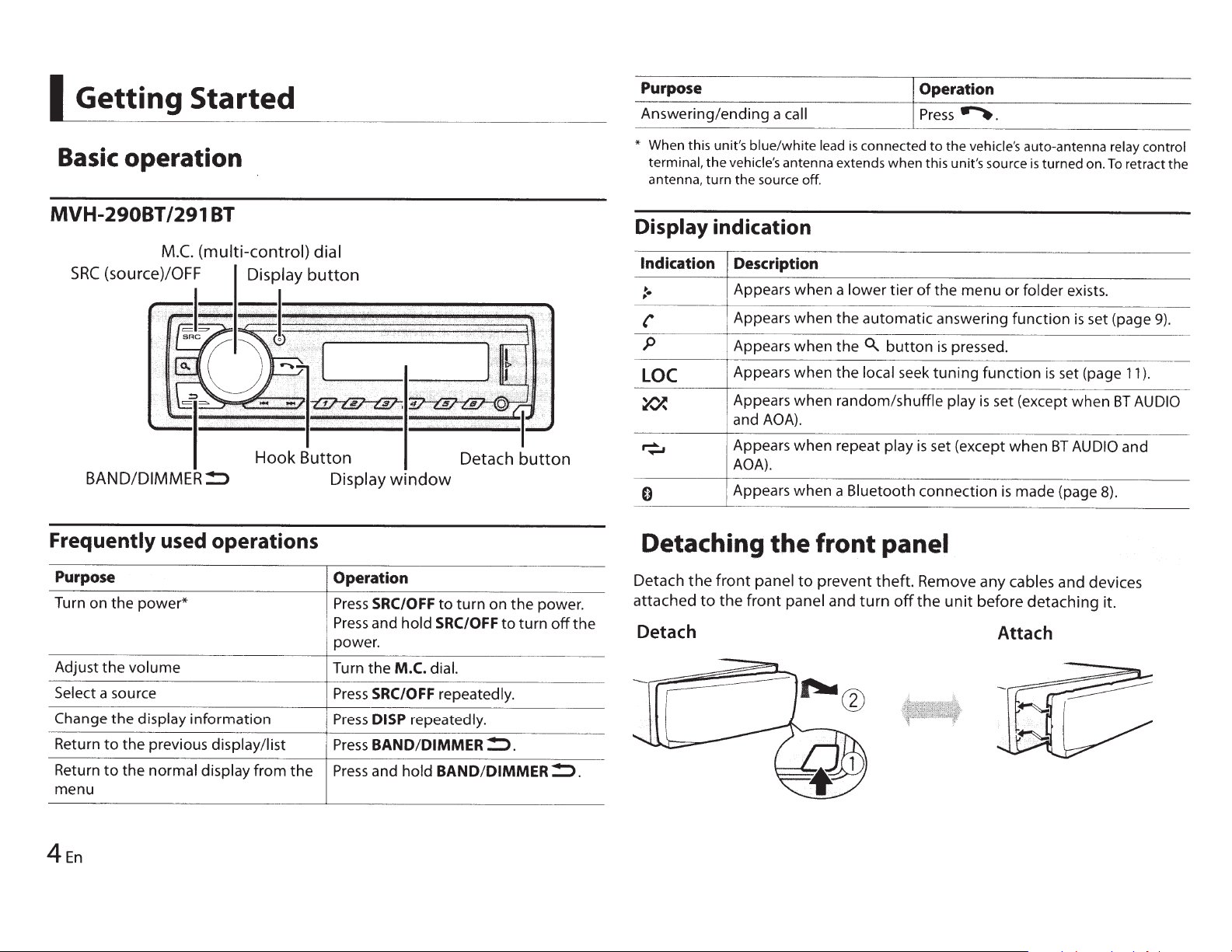
Getting Started
Basic
operation
Purpose
Answering/ending
*
When this unit's
terminal,
antenna,
the
turn
vehicle's
the source
Operation
a
call
blue/white
lead
is
connected
antenna extends when this unit's source
off
.
Press~.
to
the
vehicle's
auto-antenna relay control
is
turned on.
To
retract the
MVH-29081/291
BT
BAND/DIMMER!:> Display
Frequently used operations
Purpose
Turn on
Adjust
Select
Change
Return
Return
menu
the
power*
the
volume
a source
the
display
to
the
to
the
information
previous display/list
normal display
from
the
window
Operation
Press
SRC/OFF
Press
and
hold
power.
Turn
the
M.C.
dial.
Press
SRC/OFF
Press
DISP
repeatedly.
Press
BAND/DIMMER!:>.
Press
and
hold
Detach button
to
turn
on
the
power.
SRC/OFF
repeatedly.
BAND/DIMMER!:>.
to
turn
off
the
Display indication
Indication Description
:·
p
'
LOC
~
~
0
Appears
Appears
Appears
Appears
Appears
and
Appears
AOA).
Appears
Detaching
Detach
attached
the
to
front
the
front
AOA).
the
panel
panel
when
when
when
when
when
when
when
to
Detach
a
lower
tier
the
automatic
the
0..
button
the
local
random/shuffle
repeat
a
front
prevent
and
play
Bluetooth
panel
theft.
turn
of
the
answering
is
seek
tuning
is
set (except
connection
Remove
off
the
menu
pressed.
function
play
is
any
unit
before
or
folder
function
is
set (page
set (except
when
BT
is
made
(page 8).
cables
and
detaching
Attach
exists.
is
set (page
when
AUDIO
devices
it.
11
BT
and
9)
.
).
AUDIO
4En
Page 5
Important
~
(
• Avoid subjecting the front panel
direct
of
out
panel
front
the
• Keep
• Always
store the detached front panel
excessive shock.
to
sunlight
and high temperatures.
in a protective
case
or
bag.
2
3
4
Turn
Turn
Turn
the
the
the
M.C.
M.C.
M.C.
dial
dial
dial
select
to
select
to
select [YES],
to
then
then
press
[SYSTEM],
[DEMO OFF],
press
then
to
press
confirm.
to
confirm.
confirm.
to
Setup menu
When you
appears in the display.
Press
1
The setup
not
confirm.
Turn
2
To
Menu
CLOCK
[QUIT
3
To
Press
4
NOTES
You
•
These settings can be made at any
•
settings (page
Canceling
turn
dial.
M.C.
the
disappears
menu
set at this time,
to
dial
M.C.
the
the
:YES]
the
to
appears
the
to
then
M.C.
5).
first
press
dial
proceed
Item
SET
return
[QUIT :NO],
can cancel the menu setting by pressing SRC/OFF.
the
ignition
the
switch
turn
select
to
menu
next
when
item
to
confirm
to
demonstration
to
after
M.C.
the
options,
the
option,
Description
Set the clock.
the
all
setup menu,
the
of
confirm.
the
from
time
OFF)
after installation,
ON
seconds
30
dial
you need
settings
settings.
the
of
select
to
then
have
turn
SYSTEM
[SET
operation.
no
then
[NO],
confirm.
to
press
confirm
to
made.
been
M.C.
the
settings (page
d,isplay
:YES]
UP
you prefer
If
to
press
selection.
your
select
to
dial
INITIAL
and
12)
(DEMO
INITIAL
Press
1
Press
2
Turn
3
Turn
4
NOTE
The options vary depending on the unit.
Item
Menu
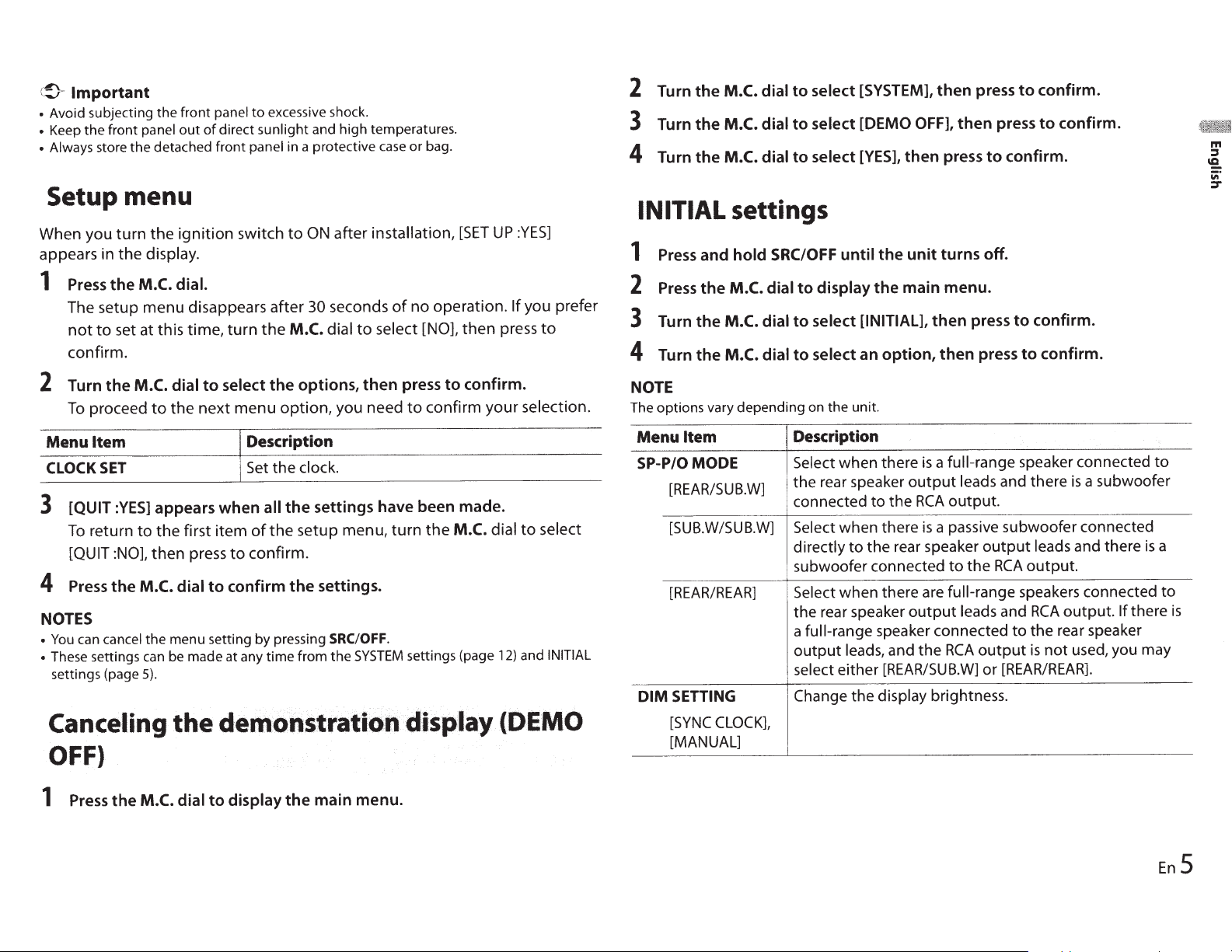
SP-P/OMODE
[REAR/SUB.W]
[SUB.W/SUB.W]
[REAR/REAR]
SETTING
DIM
[SYNC
[MANUAL]
settings
hold
and
M.C.
the
M.C.
the
M.C.
the
CLOCK],
SRC/OFF
dial
to
dial
to
dial
Description
Select when there
the rear speaker
connected
Select when there
directly
subwoofer connected
Select
the rear speaker
a
output
select either
Change the display brightness.
until
display
to
select
select
to
when there are
full-range
leads, and the
[INITIAL],
an
the rear speaker
off.
turns
unit
the
menu.
main
the
press
then
press
option,
the
to
speaker connected
[REAR/SUB.W]
then
full-range
a
is
output
output
leads and there
output.
RCA
a passive subwoofer connected
is
output
the
to
full-range
leads
output
RCA
or
confirm.
to
confirm.
to
speaker connected
a subwoofer
is
leads and there
output.
RCA
speakers connected
output.
RCA
and
the rear speaker
to
used, you may
not
is
[REAR/REAR].
there
If
is
to
a
to
is
1
Press
the
M.C.
dial
display
to
the
main
menu.
En
5
Page 6
Menu
Item
SYSTEM
I
The
signals for
RESET
[YES],
[NO]
Radio
RDS
(radio data system)
FM
Receiving
1
Press
SRC/OFF
2
Press
BAND/DIMMER!:::>
[AM].
3
Press
a
number
TIP
The~/
[PCH] in
.......
the
FUNCTION
stations.
preset
to
button
buttons
settings (page
Description
Select
[YES]
to
initialize the unit settings.
restarted automatically.
(Some
resetting the unit.)
of
the settings may be retained even after
function
only
works in areas
stations
select [RADIO].
to
can be
(1/
also
select
A
used
11
the
to
6/~).
to
select
).
band
from
[FM
a preset station
The
that
broadcast
1
],
[FM2], [FM3]
when
unit
[SEEK]
is
will
RDS
set
to
be
or
To
seek
1
After
Press
Scanning stops
press~/
NOTE
[SEEK]
To
store
1
While
number
I
USB/AUX
a station
selecting
and
needs
to
stations
receiving
buttons
the
hold
~/...,....
when
........
be set
to
[MAN] in
the
(1
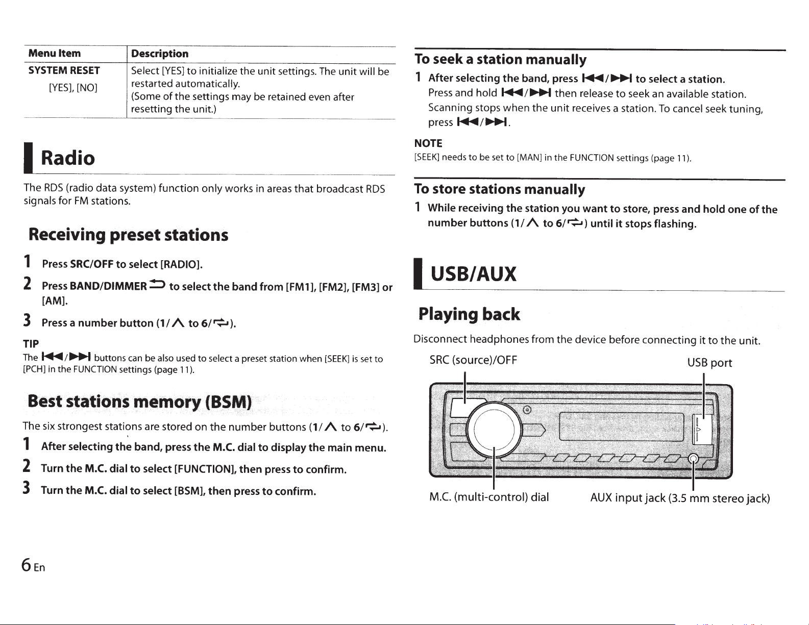
Playing back
Disconnect headphones
SRC
(source)/OFF
manually
band,
press~/...,....
then
the
unit
receives a station.
the
FUNCTION
manually
station you
I
A
to
6/~)
from
the
release
want
device before
until
to
to
it
seek an available station.
settings (page
store, press and
stops
to
select a station.
To
cancel seek tuning,
11
).
flashing.
connecting
USB
hold
it
to
port
one
the
of
unit.
the
The six strongest stations are stored
1
After
2
3
Turn
Turn
selecting
the
M.C. dial
the
M.C. dial
the
band, press
to
select [FUNCTION],
to
select [BSM],
on
the
the
then
number
M.C. dial
then
press
buttons
to
display
press
to
confirm.
(1/
the
to
confirm.
A
to
6/~).
main menu.
M.C.
(multi-control)
dial
AUX
input
jack
(3.5
mm
stereo jack)
Page 7
devices (including Android)
USB
port cover.
in
the
USB
USB.
Open the
1
Plug
2
NOTE
automatically
To
AUTO]
[USB
CAUTION
A
optional
an
Use
connected
Before removing
connections
AOA
A device
using
AOA,
Listening
function
This
installed
Press
1
switch
[ON]
to
Pioneer
directly
installed
cable
the
compatible
is
also
and
SRC/OFF
SYSTEM
the
in
USB
unit
the
to
device, stop playback.
the
Android
with
supplied
music on Android
to
support
settings (page
5.0
the
to
out
or
device.
cable
will
with
(CD-USOE)
protrude
OS
with
devices
AOA (Android Open Accessory)
to select [ANDROID].
12).
connect
the
from
can be connected
later
have Android
that
device
USB
a
when
source
[USB]
to
NOTE
work
not
the
may
OS
version.
Some Android devices connected via AOA 2.0
their
software design, regardless
own
of
Basic operations
Purpose Operation
Select
Fast
Pause/resume playback
a track Press...,...
forward or reverse
Press
I
Press
and
4/PAUSE.
connected
is
device
USB
the
unit, which
properly
or~.
...,.
hold
could
OS
2.0.
or
or
to
as
5.0
emit
~.
unit, set
the
any device
be dangerous.
unit
the
to
later
or
sounds
due
via
to
AUX
input jack.
1
2
the stereo mini
Insert
SRC/OFF
Press
plug
to select
into the
[AUX]
AUX
the source.
as
NOTE
is
[AUX]
If
(page 12).
set
to
[OFF]
in
the
SYSTEM
settings, [AUX]
cannot
be
Operations
FUNCTION
do
the
not
an
for
work
or
A
1/
Press
and
or~.
hold
to
~
M.C.
Press...,...
Press
Press
1
Turn the
2
desired file
category, then press
Turn the
3
desired
M.C.
file,
Playback
M.C.
the
Press
selected.
is
hold
and
Press
6/~.
Press
5/~.
Press
4/PAUSE.
Press
can make various adjustments in
You
Note
AUX
an
the
that
device, use
following
operations
device itself.
the
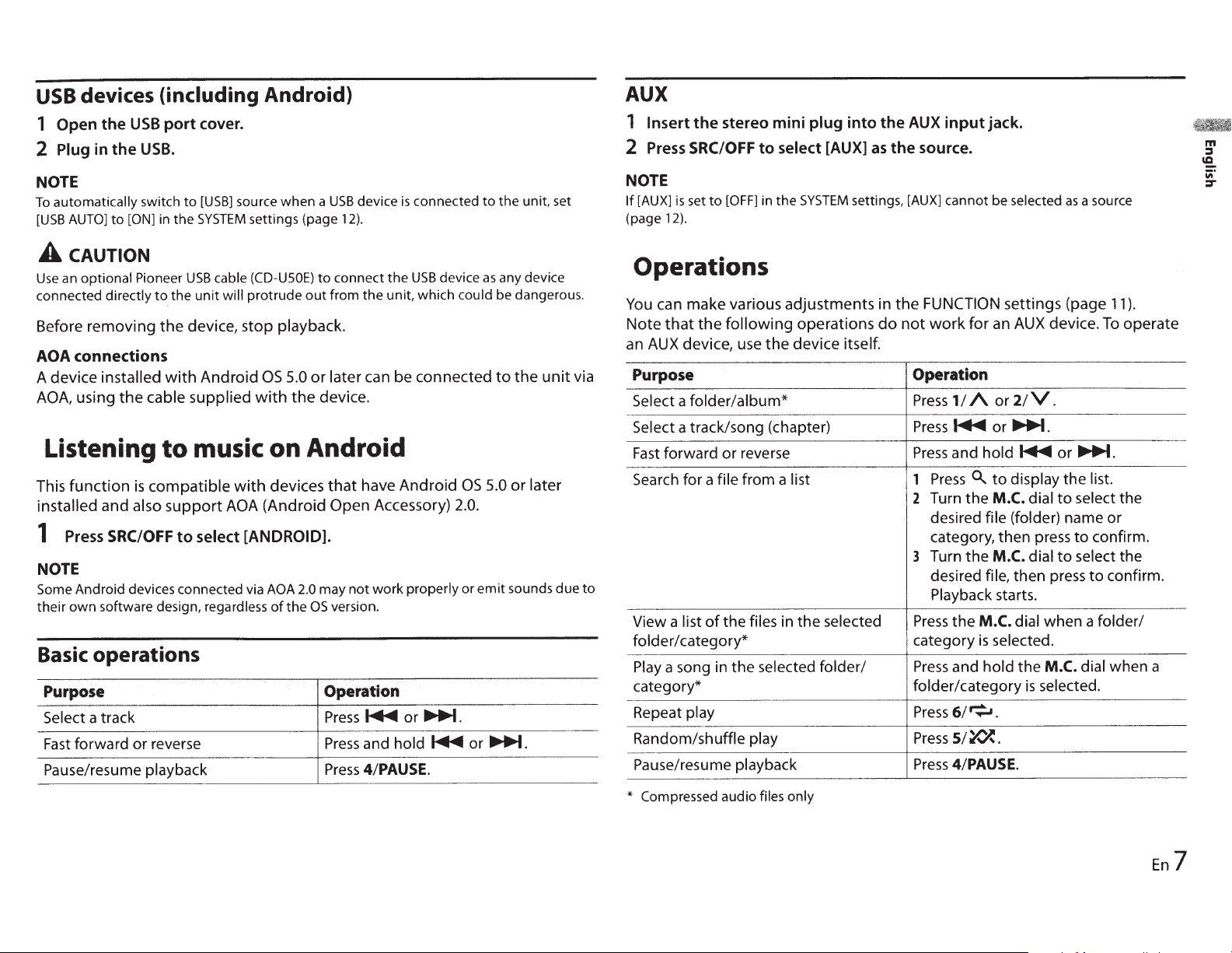
Purpose Operation
folder/album*
a
Select
a track/song (chapter)
Select
forward or reverse
Fast
Search
for a
View a list
file
the files
of
from a
list
in the selected
folder/category* category
Play
a song
the selected
in
folder/
category* folder/category
Repeat
Random/shuffle
play
play
Pause/resume playback
only
Compressed audio
*
files
a source
selected
as
settings (page
device.
AUX
2/V.
~.
or
~
list.
dial
dial
press
M.C.
the
selected.
is
the
select the
to
name or
confirm.
to
select the
to
to
dial when a
display
(folder)
then
starts.
dial when a folder/
).
11
operate
To
confirm.
m
:I
ca.
iii'
:::r
En
7
Page 8

I
Bluetooth
Bluetooth
1
Turn on
2
Press
3
Turn
4
Turn
The
•
To
• If
•
If
S
Turn
Press
between
6
Select
7
Make
then
NOTES
• Depending on the device, the
• Only
registered phonebook and preset information
is
paired/registered
TIP
The Bluetooth connection can be
device.
Bluetooth device operations, refer
Bluetooth device.
the
~
the
the
unit
cancel
the
desired device
there
the
and
[Pioneer
sure
select
one
single
To
do
so,
connection
Bluetooth
to
display
M.C.
dial
M.C.
dial
starts
to
searching, press
is
no
device
M.C.
dial
hold
the
the
Bluetooth device address and device name.
BT
the
same
"Yes"
device
to
this unit.
[VISIBLE]
function
the
phone
to
select
to
search for
available, [NOT FOUND] appears in
to
select
M.C.
Unit] shown in
6-digit
on
the
can
be paired/registered at any one time. The previously paired/
in
the
[BT SETTING],
select
[ADD
available
the
M.C.
is
not
in
the
a device,
dial
to
switch
number
device.
PIN
code
is
also
made by detecting
Bluetooth settings needs
to
the
operating instructions supplied with the
of
the
device.
menu.
then
press
to
confirm.
DEVICE],
dial.
list, select
the
required in step
then
press
to
confirm.
devices.
[RE-SEARCH].
the
then
press
to
confirm.
the
displayed
device
appears on this
is
overwritten/deleted when a new device
device
display.
?.In this
the
unit
to
be set
information
unit
and
case,
from the Bluetooth
to
[ON].
display.
the
input
[0000].
For
details on a
device,
Bluetooth settings
Menu
Item
BTCONNECT
[ON],
[OFF]
ADD
DEVICE
A.CONN
[ON],
[OFF]
VISIBLE
[ON],
[OFF]
PIN CODE
DEV.INFO
Description
Display the paired Bluetooth devices."*" appears on the
device name when the Bluetooth connection
established.
Register a new device.
Select [ON]
automatically.
Select [ON]
unit
when the
I
device.
Change
1
2
3
4
After
returns you
change the
Switch
the device name and Bluetooth device address.
the
Press
the
Turn the
Press
the
position.
After
inputting
dial.
inputting
the device information on the
Bluetooth telephone
First, make a
:!)
~
Important
•
Leaving the
not
running
•
Be
sure
unit
can
to
park your
Bluetooth
on standby
drain the
vehicle
connection
to
connect
vehicle's
in a
battery.
safe
place
to
connect
so
that
unit
PIN
code.
M.C.
M.C.
M.C.
the
to
the
PIN
code.
with
to
your phone via Bluetooth
and apply
to
a Bluetooth device
a Bluetooth device
is
connected via Bluetooth
dial
to
display the setting mode.
dial
to
select a number.
dial
to
move the cursor
the
PIN
code, press and
PIN
code, pressing the
PIN
code
input
the
Bluetooth telephone
the
is
can
detect the
to
another
to
the next
hold
the
M.C.
M.C.
dial
display, and you
display
while
parking brake before operation.
can
between
(page
8).
the engine
is
8En
Page 9

To
make a
1
Press~
2 Turn
the
M.C. dial
phone
to
display
to
call
the
select
confirm.
If
you select [PHONE
3 Turn
4 Turn
to
confirm.
the
M.C. dial
the
M.C. dial
BOOK],
to
select [MISSED], [DIALED]
to
select a name
confirm.
The
phone
To
answer an
1
Press
Basic
Purpose
End
a call
Reject
an
Switch between the current
caller and a caller on hold
Cancel a caller on hold
Adjust the volume
caller's voice (When private
mode
is
available.)
Turn the private mode on or
off
call starts.
incoming
~
when a call
operations
incoming call
of
the
on, this function
is
phone
menu.
[RECENTS]
proceed
to
or
[PHONE BOOK],
step 4.
or
or
phone number,
call
is
received.
Operation
Press~.
Press
and hold
Press
the M.C. dial.
Press
and hold
Turn the M.C. dial during the call.
not
Press
BAND/!:>
~
~.
during the call.
then
[RECEIVED],
then
when a call
press
then
press
is
received.
to
to
press
2
Press
and
hold
one
of
the
number
The
contact
To
make a call using a preset number, press
to
6/~),
Phone
Menu
Item
RECENTS
[MISSED]
[DIALED]
[RECEIVED]
PHONE BOOK* Display the contacts which have been transferred from
PRESET
A.ANSR Select [ON]
[ON],
R.TONE
[ON],
PBINVT
is
then
press
menu
1-6
[OFF]
[OFF]
stored in
the
selected preset number.
the
M.C. dial.
Description
Display the missed call history.
Display the dialed call history.
Display the received call history.
your phone.
[ON]
to
browse the contacts via this unit.
Recall
the preset phone numbers.
preset phone numbers by pressing one
buttons (1/
Select
car speakers. Depending on the connected phone, this
function may
Invert the order
view).
[ON]
buttons
Set
[VISIBLE]
A
to
6/~).
to
answer an incoming call automatically.
if
the ring tone does not come
not
work.
of
(1/ A
one
in the Bluetooth settings
names in the phone book (name
of
the
to
number
6/~).
buttons
You
can
also recall the
of
the number
out
(1/
to
from the
A
m
::::s
'2..
iii"
::::r
To
preset
phone
1 Select a phone
numbers
number
from
a phone
book
or
call history.
En9
Page 10

Item
Menu
A.SYNC
PB
[OFF]
[ON],
BTSETTING
contacts on your phone
The
*
connected.
If
they
Description
whether
Select
phone
the
•
•
•
•
You
connections. For details on Bluetooth settings,
page
not,
are
automatically
unit.
When connected
phone
your
[PB
the
you switch
If
synchronization
connection.
you switch
If
synchronization
connected
During
synchronization, even
the
can adjust various settings
8.
will normally
your phone
use
or
when
the
for
are transferred automatically, regardless
A.SYNC]
the
setting.
to
[ON]
from
be
not
will
to
[OFF]
from
performed
be
will
unit.
the
to
synchronization, you cannot cancel
auto
be transferred automatically when
transfer the contacts.
to
transfer
to
not
the
phone
your
first time,
the
[OFF],
performed
the
[ON],
you select
if
for
Bluetooth
contacts
connected
is
contacts
the
auto
on
auto
your
when
[OFF]
the
from
next
phone
.
see
the
your
to
from
phone
of
is
2
3
Press
Press
SRC/OFF
BAND/!:>
to
to start
playback.
AUDIO]
[BT
select
Basic operations
in
from
adjustments
list
a
can make various
You
Purpose Operation
forward or reverse
Fast
Select a track
Repeat
Random
Pause/resume
Search
is
play*
play*
a
for
playback
file
the
as
FUNCTION
the
and
Press
Press~
6/~.
Press
5/~.
Press
4/PAUSE.
Press
Press
1
Turn
2
desired
confirm.
Turn
3
desired
Playback
source.
hold
or~.
to
0..
M.C.
the
folder
M.C.
the
file,
starts.
settings
~
display a
dial
name,
dial
press
then
(page
~.
or
list.
select
to
then
select
to
11
press
confirm.
to
).
the
to
the
Bluetooth
Important
\!}
Depending on the Bluetooth audio player connected
•
be limited
will
(Advanced Audio Distribution Profile)
A2DP
player.
(AudioNideo Remote
AVRCP
pause, select song, etc.
The sound
•
When
•
automatically.
Depending on the type
•
operation and information displayed may vary based on
Make
1
0En
1
of
Bluetooth audio player
the
Bluetooth
a
audio
levels:
the following
to
the Bluetooth audio player
two
Control
use,
in
is
Bluetooth audio player you have connected
of
connection
can
Profile)
be muted when the phone
will
you cannot connect
the
with
this unit, the
to
back songs on your audio
play
only
perform functions such
can
to
availability
Bluetooth
audio
as
in
is
this unit,
to
operations
playback,
use.
available
a Bluetooth telephone
and functionality.
player.
Depending on the connected device, these operations may
*
Settings
I
menu.
main
the
You can
Press
1
Turn
2
confirm.
• FUNCTION
• AUDIO
SYSTEM
•
adjust
the
M.C. dial
the
settings
various
M.C. dial
settings
(page 11)
settings
settings
to
to
(page 12)
in
display
one
select
(page 11)
main menu.
the
the
of
categories
be available.
not
below,
then press
to
Page 11

3
Turn
the
M.C.
dial
to
select
the
options,
then
press
to
confirm.
Menu
Item
BALANCE
Description
FUNCTION settings
The
menu
items vary according
Menu
Item
BSM I
LOCAL I
SEEK
PLAY
STOP
RADIO
FM:
[OFF],
[LV4]
AM:
[OFF],
I
RADIO
[MAN],
jsTAUDiol
lsr
AUDIOj
RADIO
AUDIO
[LV1
],
[LV2],
[LV1
],
[LV2]
I
[PCH]
settings
to
[LV3],
the
source.
Description
Store the
number buttons
automatically.
Restrict the
signal strength.
Assign
stations one by one (manual tuning) or
select a station from the preset channels.
Start playback.
Stop playback.
six
strongest stations on the
(1/
A to
tuning
~
station according
or
~
buttons
6/~)
to
seek
to
the
the
EQ
SETTING
[SUPER
[NATURAL],
[CUSTOM 1 ],
[FLAn
Select
level for further customizing.
Equalizer
[250HZ], [800HZ], [2.5KHZ],
[8KHZ]
Equalizer level: [ +6]
LOUDNESS
[OFF],
SUB.W*2
[NOR],
SUB.W CTRL*2*3
Cut-off
[63HZ], [80HZ],
[125HZ], [160HZ], [200HZ]
Output
Slope level: [-12], [-24]
BASS
[0]
BASS],
an
[LOW], [MID],
[REV],
frequency:
level: [-24]
BOOST
to
[+6]
[POWERFUL],
[VOCAL],
[CUSTOM2],
equalizer band and
band:
[80HZ],
[OFF]
[1OOHZ],
to
[-6]
[HI]
[50HZ],
to
[+6]
Adjust the left and right speaker balance.
Select the equalizer setting.
Compensate for clear sound at
Select the subwoofer phase.
Only frequencies lower than those in the
selected range are
subwoofer.
the
Select
bass
output
boost level.
low
from the
volume.
m
j
'2.
iii'
:r
Menu
Item
FADER*1
Description
Adjust the
front
and rear speaker balance.
HPF
SETTING
Cut-off
[50HZ], [63HZ], [80HZ],
[1OOHZ],
[200HZ]
Slope level: [-12], [-24]
frequency:
[125HZ], [160HZ],
[OFF],
Only frequencies higher than the high-pass
filter
(HPF)
cutoff
are
output
speakers.
from the
En
11
Page 12

~enultem
SLA
[-4]
to
[+4]
available
Not
*1
5).
(page
available
Not
*2
5).
(page
available
Not
*3
SYSTEM
[SUB.W/SUB.W]
when
[REAR/REAR]
when
selected in [SUB.W].
is
[OFF]
when
settings
Description
Adjust
except
selected
is
selected in
is
volume
the
RADIO.
[SP-P/0 MODE]
in
[SP-P/0 MODE]
for each source
level
the
in
INITIAL
the
in
INITIAL
settings
settings
Menu Item
BTVERSION
AUTO
USB
[OFF]
[ON],
Description
system version
Displays
the
Select
[USB]
connected
Select
the
Bluetooth module.
automatically switch
to
[ON]
[OFF]
when
the
to
when
source
being connected
charging.
USB
a
unit.
USB
a
the
to
unit
the
of
to
device/
Android
device/ Android
for
just
unit
and
is
is
access
You can
Menu
CLOCK
also
Item
SET
12H/24H
[12H], [24H]
AUX
[OFF]
[ON],
BTAUDIO
[OFF]
[ON],
BTMEMCLEAR
[NO]
[YES],
to
these
menus
turned
is
unit
the
when
Description
(page
clock
the
Set
notation.
time
the
Select
using
when
[ON]
to
Set
unit.
the
connected
the
Set
Clear
information,
book, preset
to
Bluetooth signal on/off.
Bluetooth device data (device
the
code,
PIN
phone
unit.
[CLEARED]
appears
successfully deleted.
off.
5).
auxiliary device
an
history,
call
numbers) stored in
data
when
phone
is
the
12
En
Page 13

I Connections/lnstal_
Connections
A
wARNING
•
Use
speakers over
value)
(impedance
3
•
The
installing this
(sold separately),
connect the ground wire first. Ensure
that
connected
body. The ground wire
amp and the one
other device must be connected
the car
screws.
wire
result
malfunction.
Ground wire
and between
0
speakers for this unit.
black cable
the ground wire
to
separately
If
the screw for the ground
loosens
in fire, generation
'h_,
SOW
(output
4
0
to
8
0
value).
Do
is
ground. When
unit
or power amp
make sure
metal
parts
of
this
with
or falls
out, it
not
is
properly
of
of
the power
unit
different
could
of
POWER
use
1
0
to
the
car's
or any
to
smoke or
AMP
'~/;)//
la
•
to
•
*j'~t~
(-
Other
(Another
device
*1
Not
L
devices
electronic
in
the
supplied
(!) (!)
car)
for this
-
\
Metal parts
car's
body
unit
of
_
t_io
_n
_
__
!>
Important
When
installing
without
on the ignition switch,
connect the red
that detects operation
key may
ACC
Use
than the
or
-Vehicles
negative grounding.
-When
channels,
(maximum
between
value). Do
speakers for this unit.
-When
by 2
over
*Please
connection method.
•
To
overheating or
to
-Disconnect
of
-Secure
clamps
an
result in battery drain.
position
of
this
following could result in fire
malfunction.
speaker
rear speaker
0
of
70
W (maximum
prevent a short-circuit,
follow the directions
the battery before installation.
the wiring with cable
or adhesive tape. Wrap
this unit in a
ACC
(accessory) position
cable
to
No
unit
in conditions other
with
a
12-volt
output
use speakers over
input
power) and
4
0
to
8
0
(impedance
not
use
1
0
output
subwoofer,
refer
to
connection for a
malfunction,
the negative
_
vehicle
failure
of
use
to
the
terminal
the ignition
ACC
position
battery and
is
used by
SOW
to
3
0
is
used
speakers
input
power).
be sure
below.
terminal
adhesive tape around
comes into contact with metal
parts
to
protect the wiring.
-Place
-Place
-Do
- Cover
-Do
-Never
4
-Use
-Never
-Never
•
When this
are sent through the blue/white
cable. Connect
system remote control
power amp or the vehicle's autoantenna relay control terminal (max.
300m
equipped
connect
power
•
Never connect the
to
power amp.
all
cables away from moving
parts, such
seat rails.
places, such
outlet.
not
the battery by passing
the
hole
compartment.
connectors
not
power cable
share the power with other devices.
The current capacity
limited.
a fuse
cable
cables
A
the power terminal
as
the shift
all
cables away from
as
near the heater
connect the
to
the engine
any disconnected
with
shorten any cables.
cut the
wire the negative speaker
directly
band together negative
of
12
it
supply terminal.
insulation
of
this
of
the rating prescribed.
to
multiple
unit
is
this
V
DC).
with
a
glass
to
the antenna booster
Also,
wiring that
lever
and
hot
yellow cable
it
through
cable
insulating
unit
ground.
speakers.
on, control signals
cable
If
the vehicle
blue/white cable
never connect
tape.
of
the
in order
of
the
cable
to
the
of
an
external
antenna,
of
an
external
is
it
to
to
is
to
the power terminal
antenna. Doing
battery drain or a
• The black cable
cables
equipment
products such
be wired separately. If they
an
in a fire or malfunction.
This
CV
®
(3)
® Microphone
® Microphone
for this
acc
idental
unit
Rear
output
Antenna
Power cord
Fuse
(9ft.
input
(1
0
A)
10-1/8 in.)
(especially, high-current
of
the auto
so
may result in
malfunction.
is
ground. Ground
unit
and other
as
power amps) must
detachment may
or subwoofer
input
input
3m
Power cord
Perform
connecting a rear speaker
subwoofer.
these connections when
are
output
lead
not,
result
not
to
a
m
::::J
"9.
iii"
:r
En
13
Page 14

:4
:m
·
J_Z'
·H'
\
15
·
'
JZi
without
input
the
L-----L------
~----1§
L------·
Perform these connections when
using a subwoofer
optional amplifier.
1-----~
L-----(1~
L-----1])
___
.___
power cord
To
(})
Left
1J
:
Right
~)
(
Front speaker
;
(1
1
,i
CID
C!J
® Gray
~
(
QQ
speaker
Rear
:
White
White/black
Gray/black
)
Green
)
Green/black
·
QJ
Violet
·
n2:
Violet/black
q
(chassis
Black
(H
Connect
location.
metal
Yellow
•
J5:
(
Connect
supply terminal.
Red
)
,
J6
- Connect
the ignition switch
Blue/white
jf
:
Connect
-terminal
antenna
300
(max.
Subwoofer
@;
When using a subwoofer
J~)
to
sure
violet and violet/black leads
the
this unit. Do
the green and green/black leads.
to
@,Not
r
NOTE
Change the initial
Refer
subwoofer
monaural.
used.
Subwoofer
,?J
to
[SP-P/0 MODE]
Power amp
Perform these connections when
using the optional amplifier.
ground)
paint-free
clean,
a
to
V
the constant
to
terminal controlled
to
the system
to
the power amp or auto-
of
relay control
V
12
mA
0)
(4
connect the subwoofer
connect anything
not
X
0)
(4
menu
output
of
12
DC).
V
(12
control
terminal
DC).
2
this unit.
of
(page
this unit
of
2
5).
is
(sold separately)
by
0,
to
The
be
of
System remote
:·
:1
Connect
Power amp (sold separately)
;.
,2
({:Connect
separately)
To
4
Rear
5
with
output
rear
speaker or subwoofer
control
blue/white
to
RCA
or subwoofer
cable.
cables (sold
output
Installation
Important
!>
connections and systems
all
Check
•
before
Do
•
this may cause malfunctions.
• Consult
requires
modifications
• Do
-it
-it
Optimum
•
performance
obtained when
unit
angle
When
•
heat dispersal when using this unit,
make sure you
behind the rear
final installation.
unauthorized parts
use
not
dealer
your
drilling
to
this
install
not
may interfere
the vehicle.
may cause injury
a sudden stop.
of
result
a
as
is
installed
is
than
less
of
installing,
installation
if
or other
holes
of
vehicle.
the
where:
unit
operation
with
a passenger
to
Ls_
the
an
at
60°.
ensure proper
to
leave ample
panel and wrap any
space
as
of
600
they are
loose cables
the vents.
Leave
space
mount installation
DIN
Insert
1
sleeve into the dashboard.
Secure
2
using a screwdriver to bend
metal tabs
Dashboard
'T
Mounting
i
Make sure
•
installed securely in
unstable
skipping or
so
ample
the supplied mounting
the mounting sleeve by
(90°)
sleeve
that
installation
other
When not using the
mounting
line
1
mounting bracket with the holes
on the
the bracket.
sleeve
up the
sides
holes on the
of the unit
not
into place .
is
unit
the
place.
may cause
malfunctions.
supplied
to
blocking
the
An
attach
14En
Page 15

2 Screw in one screw
hold
the
unit
~
8 •
/'
'(&
8
on
in place.
each side
'
3
j
cifl
CD
Tapping screw
Cfl
Mounting bracket
®Dashboard
Using
Check
bracket matches your particular
model
the
the
included bracket
to
make sure
of
vehicle and then attach it
unit
as
shown below.
(q>S
or
console
that
mm x 9 mm)
the included
to
to
Screw
Bracket
Removing
with
the
the
unit
supplied
{installed
mounting
sleeve)
1 Remove
CD
• Releasing the front panel allows
easier
• When reattaching the
point
tab down.
2 Insert
keys
until
3 Pull
the
trim
ring.
Trim ring
Notched tab
access
the side with the notched
the
into
they
the
to
the trim ring.
supplied extraction
both
sides
of
click
into
place.
unit
out
of
the
trim
the
dashboard.
ring,
unit
To
secure
The front panel
the supplied screw.
Installing
the
can
front
be secured
Screw
the
panel
with
microphone
• Install the microphone in a place
where its direction and distance
from the driver make it easiest
pick up the driver's voice.
•
Be
sure
to
turn
off
(ACC
OFF)
product before connecting the
microphone.
Mounting
1 Fit
the
microphone clip.
on
the
microphone
sun
into
to
the
visor
the
1 Microphone
Microphone clip
2
Mount
sun visor.
CD
Install
visor when it
cannot recognize the driver's voice
if
position.
the
microphone clip
Microphone clip
Clamps
Use
separately sold clamps
secure
necessary inside
the
the
lead where
the
the
microphone on the sun
is
in the up
sun visor
is
in the down
vehicle.
position.lt
to
the
to
m
:I
~
iii"
::r
En
15
Page 16

Installation on
the
steering
column
1 Fit
the
microphone
Microphone
Microphone
Microphone
double-sided tape
2 Attach
steering column.
Base.
the
microphone
/~-r'i;;,c
/
d(T!
( \ '--------,----'
<fi
-~
I
1_
..
'
'\
~
~
\
..
~Vi-=1
"~.
~
~---
_._-~·-
.....
/ "'i :· .
..
,,
:./
.. \ \C..t
-~
...
,~,,
/7
Microphone
Clamps
Use
separately sold clamps
secure
necessary inside
3 Keeping
wheel.
the
it
away
into
the
base
with
on
the
"7~;~
~-0
~~.
Base
lead
')
,.;.,
/~--.
'~--
~
I
)/
cg;"--'-F--~--(-
'--------____./
..
-------
ll3JY
to
where
the
vehicle.
from
the
steering
I
Additionallnform~ion
-The
Troubleshooting
The display
the
normal
~
No
about
-Perform
The repeat play range changes
unexpectedly.
~Depending
range, the selected range may
change when another folder or
track
fast forwarding/reversing.
-Select
again.
subfolder
A
~
Subfolders cannot be played when
[FLO]
-Select
The sound
~You
cellular phone, that may cause
audible interference.
-Move
be causing the interference away
from the unit.
The sound
source
~There
Bluetooth-connected cellular
phone.
automatically
display.
operations have been made for
30 seconds.
an
operation.
on the repeat play
is
being selected or during
the repeat play range
is
not
played back.
(folder repeat)
another repeat play range.
is
intermittent.
are
using a device, such
electrical devices that may
from
the
is
not
played back.
is
a call in progress on a
returns
is
selected.
Bluetooth
to
as
a
audio
sound will
when the call
~
A Bluetooth-connected cellular
is
phone
-Stop
~The
and the cellular phone
established correctly after a call
made by a Bluetooth-connected
cellular phone.
-Make
between the unit and the cellular
phone again.
currently being operated.
using the cellular phone.
connection between the
a Bluetooth connection
Error messages
Common
AMP
ERROR
~This
~The
NO
~There
unit
fails
speaker connection
protective circuit
-Check
-Turn
XXXX
information.
-Switch
the speaker connection.
the ignition switch
back
to
ON
remains, contact your dealer or
authorized Pioneer Service
Station for assistance.
(NO
is
no embedded text
the display or play another
track/file.
be
played back
is
terminated.
to
operate or the
again.
If
TITLE,
for example)
unit
is
not
is
incorrect.
is
activated.
OFF
the message
and
an
16En
Page 17

USB
device
FORMAT
~
NO
~
~The
READ
Sometimes there
between the start
when you start
-Wait
until the message
disappears and you hear sound.
is
a delay
of
playback and
to
hear any sound.
AUDIO
There are no songs.
-Transfer the audio files
device and connect.
connected
security enabled.
-Follow
instructions
security.
the
USB
USB
device
to
disable the
device
SKIPPED
~The
connected
DRM
protected files.
-The
protected files are skipped.
USB
device contains
PROTECT
~All
the files on the connected
device are embedded with
-Replace the
N/A
USB
~The
HUB
~The
connected
supported by this unit.
-Disconnect
replace
device.
ERROR
USB
USB
hub
unit.
USB
device.
USB
device
your device and
it
with
a compatible
device connected via a
is
not
supported by this
to
the
has
USB
DRM.
is
not
USB
USB
-Connect
to
CHECK
~The
has
-Check
USB
something or damaged.
----?The
consumes more than maximum
allowable
-Disconnect
do
switch
ON.
devices.
the
USB
device directly
this
unit
using a
USB
USB
USB
connector or
short-circuited.
that
the
USB
connector or
cable
is
not
caught in
connected
not
use it. Turn the ignition
OFF
Connect
USB
current.
the
USB
and back
only compliant
device
USB
device and
to
ERROR-19
~
Communication failed.
-Perform
operations, then return
USB
• Turn the ignition switch
back
•
Disconnect the
• Change
one
source.
to
ON.
to
of
the
following
USB
device.
a different source.
ERROR-23
~USB
device
properly.
-Format
FAT12,
was
the
USB
FAT16
not
formatted
device with
or
FAT32.
STOP
~There
are no songs in the current
list.
-Select
a list that contains songs.
cable.
cable
ACC
to
the
OFF
or
USB
and
Bluetooth device
ERROR-10
~
The power failed for the Bluetooth
module
-Turn
back
of
the unit.
the ignition switch
to
ACC
or
ON.
OFF
Handling guidelines
USB
storage device
•
Connections via
supported.
•
Firmly secure the
before driving. Do
storage device
where
it
may become jammed under
the brake
•
Depending on the
device, the
occur.
-Operations
-The
recognized.
-Files may
properly.
-The
interference when you are listening
to
or
storage device may
device may
the
radio.
Compressed
USB
USB
not
fall
onto
accelerator
USB
following
may vary.
not
be played back
cause
audio
hubs are
storage device
let the
storage
problems may
not
USB
the floor,
pedal.
not
be
audible
compatibility
• Only
the first
displayed
the file extension) or a folder name.
32
characters
as
a file name (including
can
and
be
•
The
unit
may
not
work properly
depending on the application
to
encode WMA files.
•
There may be a slight delay at the
start
of
the playback
embedded with image data, or audio
files stored on a
numerous folder hierarchies.
•
Russian
unit
following character
-Unicode
-A
A
•
Pioneer cannot guarantee
compatibility
storage devices, and assumes no
responsibility for any
media players, smartphones, or
other devices while using this
product.
• Do
any place that
temperatures.
text
to
should be encoded in one
(UTF-8,
character set other than Unicode
that
is
used in a Windows
environment and
in the multi-language setting
CAUTION
with
not
leave a
of
audio files
USB
device
be displayed on this
sets:
UTF-
1
is
set
all
USB
loss
USB
storage device in
is
subject
6)
to
mass
of
to
used
with
of
Russian
data on
high
the
m
::::s
19.,
iii'
::r
En
17
Page 18

WMA
,---
File extension .wma
r--
Bit rate
c----·
Sampling
frequency
Windows
Audio
Lossless,
DRM
Stream
MP3
File extension .mp3
Bit rate 8 kbps
frequency
WAY
files
--
-
- - -
---
-
-
Professional,
Stream/
--
MediaTM
Voice/
video
with
48 kbps
(CBR),
384 kbps
32
kHz
Not
----
files
(CBR),
Sampling
Compatible
version
M3u playlist
MP3i
interactive), mp3
PRO
103
(MP3
16kHz
kHz,
kHz for emphasis)
2.2,
tag
Not
Not
files
File extension .wav
Quantization bits
Sampling 16 kHz
frequency
8 and 16
(MSADPCM)
(LPCM),
and
ADPCM)
----
- -- --
320
to
48 kbps
(VBR)
kHz,44.1
compatible
320
to
VBR
48kHz
to
kHz,
44.1
2.4
2.3,
compatible
compatible
(LPCM),
48 kHz
to
22.05
kHz
44.1
kbps
to
kHz,
kbps
48
(MS
(32
kHz
48
Inc.
FLAC
Copyright
Copyright
2000-2009
©
2011-2013
©
Josh Coalson
Xiph.Org
Foundation
Redistribution and use in source and
binary forms,
modification,
the
that
-Redistributions
retain
this list
following
-Redistributions
reproduce
notice, this
following
documentation
materials
with
are
following
above
the
conditions
of
disclaimer.
the
list
disclaimer
provided
permitted
provided
conditions are
source code must
of
copyright
binary
in
above
conditions
of
and/or
with
notice,
the
and
form
copyright
the
in
other
the
must
and
met
the
without
or
distribution.
Xiph.org
the
of
name
-Neither
Foundation
contributors
or
this software
written
THIS
COPYRIGHT
CONTRIBUTORS
EXPRESS
INCLUDING,
IMPLIED
MERCHANTABILITY
PARTICULAR
A
DISCLAIMED.
FOUNDATION
LIABLE
INCIDENTAL,
CONSEQUENTIAL
(INCLUDING,
the
promote
permission.
SOFTWARE
HOLDERS
IMPLIED
OR
BUT
WARRANTIES
ANY
FOR
names
the
nor
may be used
of
to
products derived
without
specific
PROVIDED
IS
AND
AND ANY
IS"
"AS
WARRANTIES,
NOT LIMITED
OF
FITNESS
AND
PURPOSE
NO
IN
CONTRIBUTORS
OR
DIRECT,
SPECIAL,
ARE
EVENT
SHALL
INDIRECT,
EXEMPLARY,
DAMAGES
NOT LIMITED
BUT
its
endorse
from
prior
THE
BY
THE
TO,
FOR
THE
TO,
BE
OR
hidden
the
that
I
1
-
I
a
of
Note
device
cannot
Example
be played back.
a hierarchy
of
n'
n:2·
Level
2
Level
1
Level
Folder number
OS:
to
01
Playback
:
§)
(
to
:j )
Copyright
trademark
Bluetooth
8/uetooth®
The
registered trademarks
Inc.
SIG,
PIONEER
trademarks and trade names are
Other
of
those
WMA
Windows
trademark
Corporation in
other
or
product
This
owned
cannot
a license
word mark and
and any use
CORPORATION
respective owners.
their
Media
trademark
or
countries.
includes
Microsoft
by
be used
from
FLAC
•
--
USB
•
4
files
be playable,
on
bit
not
the
encoder.
.flac
48kHz
bit
16
1/2 ch
--
-
files may
FLAC
depending
extension
File
Sampling 8/11.025112/16/
frequency 22.05/24/32/44.1
Quantization
rate
Channel
mode
device
There may be a slight delay
audio files
starting playback
storage device
USB
hierarchies.
folder
Playable folder Up
hierarchy practical hierarchy
Playable folders
Playable files Up
Playback
copyright-
protected files
Partitioned
device
of
USB
Sequence
The user
cannot
of
with
less
is
tiers.)
Up
Not
Only
partition
played.
.ofa.
assign
when
numerous
tiers
eight
to
two
than
500
to
000
15
to
compatible
first
the
can be
files
..
io
-
ud
folder
on
I
---
(A
numbers and specify playback
this unit. Sequence
sequences
audio
with
file depends on
connected
the
device.
files in a
LJFolder
Compressed
n:
1
audio
n)
n:I
Level
3
sequence
and
owned
such marks
of
is
either a registered
is
United States
the
technology
Corporation
distributed
or
Microsoft Licensing,
USB
file
4
are
logos
Bluetooth
by
by
under license.
Microsoft
of
and/
and
without
18En
Page 19

PROCUREMENT
GOODS
DATA,
INTERRUPTION) HOWEVER CAUSED
AND
WHETHER
LIABILITY,
NEGLIGENCE
IN
SOFTWARE,
POSSIBILITY
OR
OR
ON ANY THEORY
ANY
WAY
OF
SERVICES;
PROFITS;
IN
CONTRACT,
OR
TORT
OR
OTHERWISE)
OUT
EVEN
OF
SUCH
SUBSTITUTE
LOSS
OR
BUSINESS
OF
LIABILITY,
STRICT
(INCLUDING
OF
THE
USE
IF
ADVISED
DAMAGE.
OF
USE,
ARISING
OF
OF
THIS
THE
Android™
Android
is a trademark
of
Google
Inc.
Specifications
General
Power source:
DC
(1
0.8 V
to
15.1
SO
mm
3-7/8
mm
5/8
mm
3-7/8
mm
5/8
V
type
x 97
in.)
x 17
in.)
x 97
in.)
x 17
in.)
14.4 V
allowable)
Grounding
Maximum
10.0A
Dimensions
DIN
Chassis: 178
mm
(7
Nose: 188
(7-3/8 in. x
D
Chassis: 178
mm
(7 in. x 2 in. x
Nose: 170
(6-3/4 in. x
Weight:
0.5 kg
Audio
Maximum
system:
current
power
consumption:
(W
x H x D):
mm
in. x 2 in. x
mm
2-1/4
mm
mm
1-3/4
(1.1
output:
Negative
x
x 58
in. x
x 50
x46
in. x
lbs)
mm
mm
• 50 W x 4
subwoofer)
• 50 W x 2
0 (for
Continuous
22 W x 4
THO, 4 0 load,
driven)
Load
impedance:
4 0 (4 0
Preout
Loudness
Equalizer (5-Band Graphic Equalizer):
Subwoofer
maximum
+ 10 dB (100Hz), +6.5 dB
(volume:
Frequency: 80
2.5 kHz/8 kHz
Equalization range:
±12
Frequency:
1
00
Slope:Gain:
Phase: Normal/Reverse
ch/4
ch/4
subwoofer)
power
(SO
to
contour:
-30
dB
(2
dB step)
(mono):
Hz/125
12
dB/oct,
+6
dB
0 (for
no
0 + 70 W x 1
output:
Hz
to
15
000 Hz, 5 %
both
channels
8 0
allowable)
output
SO
Hz/160 Hz/200
to
level: 2.0 V
dB)
Hz/250
Hz/63 Hz/80
-24
-24
dB
Hz/800
dB/oct
ch/2
(10kHz)
Hz/
Hz/
Hz
USB
USB
standard specification:
USB
2.0
full
speed
Maximum
USB
File system:
MP3
current
Protocol:
MSC (Mass Storage Class)
(Android
AOA
2.0
decoding
MPEG-1 & 2
FAT1
format:
supply:
Open
2,
FAT16,
Audio
500 rnA
Accessory)
FAT32
Layer 3
WMA
decoding
Ver.
7,
(Windows
FLAC
decoding
v1.2.1 (Free Lossless
Codec)
WAV signal
Linear
compressed)
FM
tuner
Frequency
87.9
Usable sensitivity:
dBf
1 1
30 dB)
Signal-to-noise
network)
AM
tuner
Frequency
Usable sensitivity: 25
Signal-to-noise
58 dB
format:
7.1,
8, 9 (2
Media
format:
format:
PCM & MS
range:
MHz
to
107.9
(1.0
~V/75
ratio: 72 dB (IEC-A
range:
530kHz
ratio:
(IEC
-A
network)
Bluetooth
Version:
Output
Frequency
Bluetooth
Bluetooth
power:
+4
dBm
band(s):
400
MHz
2
profiles:
GAP (Generic Access Profile)
SOAP
(Service Discovery
Application
HFP
(Hands Free Profile) 1.6
PBAP
(Phone Book Access Profile)
A2DP (Advanced
Distribution
3.0 +
Maximum
to
2 483.5
Profile)
Profile)
ch audio)
Player)
Audio
ADPCM (Non-
MHz
0,
mono,
~V
{S/N: 20 dB)
EDR
(Power class
Audio
S/N:
to 1 710kHz
certified
MHz
AVRCP
Control
SPP
(AudioNideo
Profile) 1.5
(Serial Port Profile)
CEA2006 Specifications
Power
S/N ratio: 77 dBA (reference: 1 W
NOTE
Specifications
subject
notice.
2)
output:
(4
0
and~
40)
to
modifications
14 W
1 % THD+N)
and
the
Remote
RMS
x 4 Channels
design are
without
1.1
into
En
19
Page 20

Visit our
Register
website
your
Visitez notre site
I
product
at
Web
site nuestro sitio
Vi
I
Enregistrez votre produit au
Registre su producto en
http://www.pioneerelectronics.com
Canada
in
au Canada
Canada
en
-Learn
product.
- Register your product to receive notices about product updates and to
safeguard purchase
-Access
and much more.
lnformez-vous sur
-
les
que
- Enregistrez votre produit afin de recevoir des notifications concernant les
mises a
achat dans nos
- Accedez aux modes
rechange
http://WWW.pioneerelectroniCS.C8
about product updates (such as firmware updates) for your
or theft.
in the event of
a
jour
files
disponibles
details in our
owner's manuals,
les mises
a jour du firmware).
mises
spare parts information, service information,
jour du produit, ainsi que pour sauvegarder
fichiers en cas de perte ou de
aux informations
beaucoup d'autres informations.
eta
l'entretien,
eta
d'emploi,
vol.
loss
pour votre produit (telles
les details de votre
relatives
aux pieces de
Web
PIONEER CORPORATION
28-8, Honkomagome 2-chome, Bunkyo-ku,
113-0021, Japan
Tokyo
INC.
PIONEER ELECTRONICS
Box
P.O.
(800)
TEL:
PIONEER ELECTRONICS
Ferrier Street, Unit
340
TEL: 1-877-283-5901
TEL: 905-4 79-4411
PIONEER
Haven 1
(0)
TEL:
PIONEER ELECTRONICS ASIACENTRE PTE. LTD.
2 Jalan Kilang Barat,
TEL: 65-6378-7888
PIONEER ELECTRONICS AUSTRALIA
5 Arco Lane, Heatherton, Victoria,
TEL: (03) 9586-6300
PIONEER ELECTRONICS
Blvd. Manuel Avila Camacho 138,
Coi.Lomas de Chapultepec, Mexico,
: 52-55-9178-4270, Fax: 52-55-5202-3714
Tel
$'t~~&~~1}P]
.g::jtrtJpg~M~Iffll:J'C~g4Q7~8fl
~~~:
$'til~f-
~~nft~~5j;;~m:gog~m5fl
: 852-2848-6488
~~~
Long Beach, California
1540,
421-1404
EUROPE NV
Keetberglaan
087,
3/570.05.11
886-(0)2-2657-3588
~~1}
=i=~§)
(
(USA)
CANADA,
OF
Markham,
2,
B-9120 Melsele, Belgium/Belgique
1,
, Singapore 159346
#07-01
MEXICO S.A. DE C.
DE
6]
90801-1540,
INC.
Ontario L3R 2Z5, Canada
PTY. LTD.
Australia
3202
piso
10
11000
D.F.
U.S.
V.
A.
- lnformese de las ultimas actualizaciones (por ejemplo, actualizaciones
producto.
de firmware) para
su
- Registre su producto para recibir informacion sobre actualizaciones
compra en
su
producto y para mantener
nuestros archivos en caso
- Acceso a
manuales
recambio y mucho
©
©
2016
2016
PIONEER
PIONEER
CORPORATION.
CORPORATION.
seguridad de
Ia
perdida o robo.
de
los detalles
de instrucciones, informacion sobre piezas de
mas.
rights reserved.
All
reproduction
Tous droits
de
de
et
de
traduction
del
reserves.
127075007028>
<
uc
Page 21

PIONEER ELECTRONICS
(USA)
GARANTIE
Pioneer
Electronics
avoir
ete installes
vice
de
fabrication,
Les unites ou pieces
LA
PRESENTE
A
CONDITION
OU
UNE
AUTRE
LA
PREMIERE
PAYS
OU
L'ACHAT A
PUSAOU
POC,
PERIODE
Produits
La
peri
ode
de
ELEMENTS NON COUVERTS
UN
PRODUIT ACHETE CHEZ
IMPLICITE
" AVEC TOUS SES DEFAUTS EVENTUELS ".
PIONEER N'EST
PIONEER
DE
TOUTE APPLICATION
LA
PRESENTE
DOCUMENTS S'Y APPLIQUANT.
LA
PRESENTE
PENDANT
LA
PRESENTE
DISQUES
PAR
ECRIT
LES DOMMAGES
CONFORMES
LA
PRESENTE
PRESENTE
PIONEER.
NON AUTORISEES, Nl
LES NUMEROS
INVALIDITE
AUX
ETATS~UNIS
DE
QUALITE MARCHANDE
APRES
LA
L'EXCLUSION
S'APPLIQUER
ETAT
A L'AUTRE.
AU
CANADA-
QU'ELLE
SOIT IMPLICITE,
(USA)
Inc.
et
utilises
seront
de
GARANTIE
QUE
LE
PRODUIT
PREUVE D'ACHAT
LOCATION.
ETE
LE
CAS
DE
GARANTIE DES PRODUITS
stereo
pour
garantie pour
DE
QUALITI~
PAS
NE
GARANTIT
GARANTIE
GARANTIE
DE
LONGUES PERIODES
GARANTIE
OU
AUX
RUBANS
PAR
PIONEER,
SUBSEQUENTS
A
CELLES
GARANTIE
GARANTIE,
LA
PRESENTE
DE
SERlE MODIFIES, OBLITERES
DE
TOUTE
• PIONEER LIMITE SES
PERIODE
OU
LA
A
VOUS.
SOUS RESERVE
(PUSA)
conformement
repares
LIMITEE
AIT
51
JAMAIS
EFFECTUE
PAIERA
ourem
fournies en vertu
S'APPLIQUE
ETE
VALIDE
UN
SEULEMENT,
rechange
ECHEANT,
l'auto
les clients
qui
louent le
UN
DISTRIBUTEUR NON AUTORISE N'EST COUVERT
MARCHANDE
RESPONSABLE
PAS LES PRODUITS ENUMERES CI-DESSUS
INDUSTRIELLE
NE
S'APPLIQUE
NE
COUVRE PAS LES
NE
COUVRE PAS
OU DISQUES D'ENREGISTREMENT, LES DOMMAGES
D'UN
ACCIDENT
QUI SONT
NE
COUVRE PAS
51
ELLES
SONT
GARANTIE
D'UN
ENTRETIEN INADEQUAT.
AUTRE
OU
DE
D'ADAPTATION
GARANTIE. CERTAINS ETATS
LIMITATION DES DOMMAGES CONSECUTIFS OU INDIRECTS. LES LIMITATIONS
LA
PRESENTE GARANTIE VOUS DONNE DES DROITS LEGAUX
DE
OBLIGATOIRE
et
Pioneer
places
ACHETE
INDIQUANT
SERVICE
POURVOUS
produitcommence
PAR
OU D'ADAPTATION
DE
QUELQUE
(IMAGES
DECOULANT
SPECIFIEES
NE
GARANTIE
CE QUI EST EXPRESSEMENT STIPULE DANS LES PRESENTES,
SERVICE
Pour
profiter du service en vertu de
indiquant
AUX
Votre
de
Votre
Veuillez
Ia
Pioneer
ci-dessous
AU
Communiquez
Expedition
en
pendant
Pour
Satisfaction
Pour
REGLEMENT
AUX
recours au Programme de
de resolution des plaintes avant de
Improvement
Pour
problt~me
distributeur
resolution
par
a
AU
No. du
Dated~chat
ETATS-UNIS -
marchand
caisse
societe
acceder
plus
proche.
Customer
CANADA
port
prepaye
le
toutes
le
raccordement
ETATS-UNIS
avoir
ecrit
votre
plainte
CANADA-
modele
l'endroit
et
Ia
date
Communiquez
Pioneer
devrait
de
pour
avec
de
votre
transport.
les plaintes
de
Ia
autorise
enumerer
service autorisee -
au site
Web
Support-
communiquer
POC
a
desigl)e
Pioneer
unite
et
selon
une
lncluez
et
clientele
au 1-877-283-5901.
ou
le
DES CONFLITS
-
Si
un
Act, 15
recours
auquel
vous
pour
U.S.C.
au
Programme
vous
I
marchand
Communiquez avec
•
faites
autorise
sera
communique
vous
aviser
par
ecrit
pour
•
________________________
Ia
de
ses
de
Ce
Electronique du
aux
votre
problemes
fonctionnement
conflit
resolution
2301
des
garantie
Ia
transaction
avec
- Votre
coordonnees
Celle-ci
Pioneer
a
service
peut
avec
Pioneer
un certain
fins
de
methode
de
nom
,
aux Etats-Unis ,
AUX
CUSTOMER
PIONEER
LONG
BEACH,
http
•/
lwvvw
se
produit
des plaintes de Pioneer
vous
et
s.s.
de
face
et
les
aupres
.
Pioneer
demarches
vous
indiquer
le
directeur
un
marchand
service
vo~re
ELECTRONICS
resolution
PRENEZ SOIN
INC.
GARANTIE VALl
Electronique
au
manuel
par
une
de
Ia
AU
PROPRIETAIRE
CHEZ
UN
LA
DE
REPARATION
TEL
QU'IL
RETOURNER
LA
GARANTIE
DOMMAGE CONSECUTIF ET(OU) INDIRECT
OU
COMMERCIALE
PAS
51
TELEVISEURS
REMANENTES).
LE
COFFRAGE
,
D'UN
DE
DANS
LE
COUT DES PIECES OU
OBTENUES
COUVRE PAS LES DEFECTUOSITES OU LES DOMMAGES
OU
OBLI~ATIONS
A
UN
OU
AUTRE,
aux
par
le
premier
des
partenaires
Pioneer
(numeros
peut
reparer
www.pioneerelectronics
vous
aviser
par
telephone
nombre
de
Canada
- Si
transport
adresse
de votre unite, ou
ETATS-UNIS
SUPPORT
P.O.
BOX
CALIFORNIA
1-800-421-1404
.
pioneerelectronics
entre
prevaloir
demarches
duquel
vous vous
etudiera
qu'elle
les
raisons
de
Ia
Satisfaction de
ENREGISTREZ
DE
SEULEMENT DANS
du
de
unite
presente garantie
DISTRIBUTEUR
LE
USAGE
FUITES, LES DOMMAGES
AUPRES
ENLEVES
USAGE PARTICULIER,
Etats-Unis
(les
vous
pouvant
1720
vous
de
des
entreprendra
Canada, Inc.
l'utilisateur inclus
de
valeur
INITIAL
DATE
DE
L'ACHAT
EST
EST
le JOurou le
PRODUIT
NE PERMETTENT
NE
de
des
,
societes
coordonnees
et
communiquez
vos
que
le
DE GARDER
REQUIS,
EXPLIQUE
LE
PRODUIT
produitest
A
UN
USAGE PARTICULIER
QUE
A ETE SOUMIS
OU LES ECRANS
OU LES ELEMENTS ESTHETIQUES, LES ANTENNES
INAPPROPRIE
LE
MANUEL
D'UNE
ANNULENT LA
EN
VERTU
$'APPLIQUE
et
au
proprietaire.
Pioneer
peut
reparer
telephone
Ia
plupart
.
com
options
par
courrier ou
de
service autorisees partout au
expediez
etre
suivie
un
numero
pour
trouver
(USA)
INC.
90801
.
com
et
Pioneer apres
pour
droits
ou
plaintes,
appelez
vous
avez
etes
conflit
et,
pour
lesquelles
Ia
clientele
LE
LIEU
CETTE INFORMATION
GARANTIE LIMITEE
(POC)
avec
l'unite, ne
comparable, au
peuvent
AINSI
OU
CE SOIT.
DE
suivants
des
de
l'unite,
de
avec
procure
pour
etre
QU'A
TOUT
MARCHAND
INITIAL
OU,
LE
PRODUIT
DANS
LE
PRESENT
REPARE
utilise
pour
LORSQU'ILS
OU
D'UN
DE
SOURCE
Canada,
et
,
service
se trouvent
resoudre le
de
dans
DECOULANT
L'UTILISATEUR
DE
LA
MAIN-D'CEUVRE QUI
PRESENTE GARANTIE DANS SA TOTALITE.
TOl/TE GAR.ANTIE
A UNE
PAS
LA
ACE
PRODUIT.
vous
pour
ou
remplacer
de
telecopieur
produits
cliquer
sur
optimales
par
le
biais
vous
et
assuree
telephone
le
service
une
societe
Ia
reponse
chercher
au 1
entreprises
le
produit
un
delai
resoudre
elle
n'entreprendra
au
(905) 946-7412
ET
LA DATE
LE
PAYS
OU
garantissent
choix
neuves
PROPRIETAIRE
PIONEER
51
VOUS
OU
REMPLACE, A
Ia
premierefois
A UNE PUISSANCE
ENDOMMAGES
AU
USAGE ABUSIF, LES DOMMAGES PRODUITS PAR
AUTRE QU'UNE
PERIODE
LIMITATION
devez
le
service
electroniques
l'onglet"
de
son site Web.
ci-dessous)
devez
.
Emballez
ou
nous
de
de
conflit.
reparation en
800
421-1404
pour
de
le
D'ACHAT
No
.
Achetede
que
fonctionnent
de
PUSAou
ou
remises
SUBSEQUENT
AUTORISE
LOUEZ
DOlT
DOCUMENT
PAR AUCUNE
SONT UTILISES
PRODUIT
votre
,
courriel
pour
l'emballer
Soutien
service autorisee,
Pioneer.
quarante
conflit,
de
ET
LE
ETRE
EXPEDIE
L'INTERIEUR
(a)
QUE
CE SOIT.
QUE
CE
DECOULANT
DE
PILES DEFECTUEUSES OU
.
SOCIETE
IMPLICI!E
N'EXCEDANT
DE
LA
SPECIFIQUES. VOUS POUVEZ JOUIR
presenter
•
unite
, ou bien
,
etc.)
pour
Support
votre
modele
Canada
pour
le
produit
pouvons
a
Ia
a
une demande initiale faite au service de
Ce
programme
vertu
et
expliquez
faire
reparer
Une
(40)
et
indiquera
aucune
pour
discuter
POUR
serie •
-----------------------------
•
-------------------------------
VOTRE
RE<;U
LE
PRODUIT
les
produits distribues
pas
de
favon
de
POC,
a
neuf, au
AUX
ETATS-UNIS
PRODUIT
PENDANT
.
VOUS
ETES
pendant
Ia
GARANTIE EXPRESSE
DE
SOIT.
A
DES FINS
NOMINALE
EN
RAISON
SERAIENT
CAUSES
QUE
PAS
DUREE
AUCUNE
votre
releve
vous
.
l'auto
et
"
et
choisir"
et
si
jamais
trouver
une
soigneusement
au
vous
joindre
clientele
appelez
GROUPE
vous
du
Titre
le
produit
fois
jours
demarche.
de
REFERENCE
D'ACHAT DANS
A
appropriee
sans
que
choix
de
DU
PRESENT
OU
,
VOTRE
CONTRAT
LA
RESPONSABLE
DU
PAYS
OU
peri
ode
de
location
PLUS,
CE
EXCEDANT
DE
L'APPLICATION
INSTALLEES
D'UNE
AUTREMENT
DE SERVICE OU
PAR
L'UTILISATION
CE
SOIT
1
LA
PERIODE
D'UNE
GARANTIE IMPLICITE,
ET
EXCLUSIONS ETABLIES CI-DESSUS PEUVENT
REPRESENTATION,
de
caisse ou, si
diriger
vous
aviser
Find a
votre
emplacement
vous
societe
et
moyen
de
pendant
au 1-800-421-1404. Au
ou ecrivez
DE
PIONEER
340
httpJ/www.pioneerelectronics
est
offert
I de
Ia
au
representant
pendant
que
votre
a
pres
Ia
combien
votre
plainte
ULTERIEURE
PIONEER ELECTRONIQUE
En~
ACHETE
par
dans
vous
deviez
PUSAou
AU
CANADA.
PERIODE
L'ACHAT A
PUSAaux
PRODUIT
Etats-Unis
des
conditions d'utilisation
payer
pour
de
POC.
DE
LOCATION
DE
GARANTIE,
DU
DEMONTAGE
ETE
les
PIONEER
VOUS
DEVREZ
INDIQUANT L'ENDROIT
EN
EFFECTUE
et
par
pieces ou
PENDANT
FOURNIR
PORT
ET
DE
L'INSTALLATION
.
Pieces
DU
POC
les
LA
PREPAYE,
1 an
ou (b) a
pres
Ia
vente au
detail. selon
OU
PRODUIT EST STRICTEMENT VENDU "
COMMERCIALES
RETOUCHE,
Y
COMPRIS
vers
Service
avez
de
l'envoyer
materiaux
IMPLICITE, Y COMPRIS
OU
CELLE
QUI
D'IMAGES
PAR
L'UTILISATEUR,
D'UNE
DE
L'UTILISATION
OFFERTES
AUTRE
AUTORISEE OU DESIGNEE
D'UNE
ENTRE
DE
GARANTIE.
D'AUTRES DROIT$, QUI
GARANTIE
vous
louez le
une
societe
de
des
options
supplementaires
Center"
pour
geographique
besoin
de
a
une
coussines
de
services
societe
bureau.
Canada,
service autorisee.
les
heures
PROFESSIONNELLES,
A
ETE
MODIFICATION NON AUTORISEE
LA
FOUDRE OU
SANS
MAIN-D'CEUVRE OU
AUTRES LES GARANTIES IMPLICITES
AUCUNE GARANTIE
ET
CERTAINS
service
trouver
.
Veuillez
de
adequats
ce qui se produit en
ETABLIE
STATIQUES
LES DOMMAGES
DE
PILES NON
FRAIS
EN
PEUVENT
,
OBLIGATION
produit, votre
Pioneer
qui pourraient
Ia
societe
consulter
de
reparation
service
autorisee
pour
communiquez
a •
AU
CANADA
SATISFACTION
ELECTRONIQUE
FERRIER
MARKHAM,
(905) 4 79-4411
1-877-283-5901
sans frais. Vous devez
loi
Magnuson-Moss Warranty-Federal Trade
Ia
periode
plainte
a
reception
de
temps
et resoudre rapidement
UN
ENDROIT SUR
STREET,
ON
du
service
ete
de
ces
DE
DU
UNIT
L3R 2Z5
Soutien
a
de
garantie,
expliquee
votre
plainte,
demarches
LA
CLIENTELE
CANADA
2
.ca
a
Ia
Ia
clientele
au
le probleme.
, INC.
clientele,
avoir
recours
puis
representant,
(1)
repondra
prendront
<
CANADA,
au
Canada
normales
travaux
PERIODE
UN
RELEVE
A
Main-d'ceuvre
en raison d'un
de
reparation.
DE
GARANTIE,
ET
LA
L'INTERIEUR
DU
1
QUELQUE
DANS LES
LA
NE
autorisee
eviter
qui
donnez-lui
GARANTIE
TEL QUEL
OU
ET
IMMOBILES
SURTENSION,
VERTU DE
PAR
DE
PIECES
NE
S'APPLIQUE
PERMETTENT PAS
DONC
VARIER
OU CONDITION,
contrat
de
. Votre
s'appliquer
de
service
les
coordonnees
pour
votre produit.
ou
a
les
dommages
avec
le
vous
pouvez
au
Programme
Commission
vous
repondra
le
un
numero
a
votre
;
ou
(2)
QRY3001-B/N
lmprime
en
Tha
INC.
qui,
apres
DE
CAISSE
DATE
PRODUIT
an
premier
"
AU
SEIN
AUX
LA
NE
PAS
D'UN
location
reyu
Pioneer
Pioneer
groupe
avoir
nom
plainte
repondra
>
.i
lande
DE
DU
ET
de
le
du
de
.
.
.
,
Page 22

PIONEER ELECTRONICS (USA) INC.
WARRANTY
VALID ONLY
WARRANTY
Canada, Inc. (POC), warrant that products distributed by PUSAin the U.S.A., and by
Electronics
Pioneer
properly
function
comparable value,
of
a unit
rebuilt
new or
THIS LIMITED
PRODUCT
RECEIPT OR OTHER
DATE
AND
PREPAID, ONLY FROM WITHIN
PRODUCT.
THE
PRODUCT
Stereo
Car
The warranty period for retail
IS
WHAT
THIS PRODUCT
IF
OF MERCHANTABILITY
PIONEER
PIONEER DOES NOT
WARRANTY
THIS
WARRANTY
THIS
WARRANTY DOES
THIS
DAMAGE
UGHTNINGORTO
SPECIFIEDINTHEOWNER'SMANUAL.
THIS
OBTAINED FROM
DEFECTS
ALTERED, DEFACED,
TO THE
WARRANTY
(USA)
under
at the option
WARRANTY
PURCHASED
WAS
OF FIRST
PUSAOR
WARRANTY
Products
use due to a manufacturing defect when
normal
at the option
PUSAor
of
APPLIES
FROM
PROOF
VALID
RENTAL.
POC,
IN
THE
AS
PERIOD
customers who rent the product commences upon the date product is first put into use (a) during the
NOT COVERED
WAS PURCHASED
AND THE
BE
NOT
SHALL
WARRANT
DOES NOT
DOES NOT
NOT COVER THE
PRODUCT
POWER SURGES, SUBSEQUENT DAMAGE
DOES
SOURCE
ANY
DAMAGE
OR
OR
LIABLE
APPLY
COVER
RESULTING
NOT
CAUSED
REMOVED
IMPLIED
ANY
COVER
OTHER
BY
(PUSA), and Pioneer
Inc.
Electronics
POC ,
PUSAor
of
POC .
ORIGINAL
THE
TO
AUTHORIZED
AN
PURCHASE
OF
THE
COUNTRY
APPROPRIATE,
FROM
FOR
PRODUCT
IF
DISPLAY SCREENS
THE USE
SERIAL
SERVICE IS REQUIRED,
EVENT
OF
UNAUTHORIZED DISTRIBUTOR,
AN
WARRANTY
CONSEQUENTIALAND/OR
ANY
LISTED
PRODUCT
THE
CABINET OR ANY
ALTERATIONS,
FROM
COST
THE
PIONEER AUTHORIZED SERVICE COMPANY
THAN A
OF UNAUTHORIZED
NUMBERS
PURCHASE
WILL
OF
Of
without charge to you for parts or
SUBSEQUENT
ANY
OR
PIONEER
SHOWING
OF FITNESS
THE
AS
RETURN
TO
PAY
WHEN
ABOVE
BEEN
HAS
DAMAGED
APPEARANCE ITEM, USER ATTACHED ANTENNA,
MODIFICATIONS NOT AUTHORIZED
FROM LEAKING,
OR
PARTS
VOID THIS ENTIRE
NO OTHER WARRANTIES
FITNESS
AND
RIGHTS
EXPRESSLY
AS
LIMITS
MERCHANTABILITY
WARRANTY
OR
YOU SPECIFIC
CANADA-
IN
OR OTHERWISE,
PERIOD. SOME
LIMITATIONS OF INCIDENTAL OR
LEGAL
EXCEPT
APPLICABLE
PIONEER
U.S.A.-
THE
IN
OBLIGATIONS
ITS
PARTICULAR PURPOSE,
FORA
NOT
DO
STATES
CONSEQUENTIAL
MAY HAVE
YOU
AND
PROVIDED HEREIN,
TO THIS PRODUCT.
ALLOW
UNDER
LIMITATIONS ON
DAMAGES, SO
RIGHTS WHICH MAY VARY FROM
OTHER
THERE
TO OBTAIN SERVICE
the U.S.A. or Canada
In
contact
Please
-
USA
Your Authorized
contact
the
list
Your Authorized
website at
Pioneer
Customer
Pioneer
access
or
email
CANADAShipping
Use adequate padding
On
POC
Your
all complaints
CUSTOMER SUPPORT
to receive warranty service you need to present your
partners
following
the
of
one
Your
Dealer-
Pioneer
information (phone
Company-
Service
Pioneer
www.pioneerelectronics.com
advise
Pioneer
number
Service-
material
Can
website to
Authorized
of
Please
to prevent damage
the
has a
Unit
Support-
for
and concerns
For hook-up and operation
LONG
Service
BEACH,
Authorized
Pioneer
may repair
Dealer
Pioneer
, fax, email,
number
Can
optimal
the
contact
Service
package it
U.S.A. call
the
in
THE
IN
Company,
PIONEER ELECTRONICS (USA) INC . PIONEER ELECTRONICS OF
I
BOX 1720 340 FERRIER STREET, UNIT
O.
P.
etc.) for your
perform
and
service
.
Pioneer
Companies
carefully
transit.
in
Customer
A.
U.S.
your unit or to
of
please call
CALIFORNIA 90801 MARKHAM,
obtain
to
repairs for
"Support"
on
click
option for your
should
and send
your name, address and
Include
1-800-421-1404 (905)
http://www.pioneerelectronics.com
DISPUTE RESOLUTION
initial request to
response to
IN
Resolution
before you exercise any rights
To
have the product repaired during the warranty period and the name
has been
(1) respond to your
informing you why it
IN
Program to
use the Complaint Resolution
explained
the Customer Satisfaction Manager at (905) 946-7 412 to discuss your
CANADA-
Call
Following
U.S.A. -
THE
our
the dispute. The
resolve
under
Program
to the representative , a
complaint
will
writing informing you what action Pioneer
in
not take any action.
any
Complaint
remedies, created by
any
seek
or
,
1-800-421-1404 and
call
resolution
number will
Customer
Resolution
LIMITED
installed
DISTRIBUTOR/DEALER
DATE
EXPLAINED
PARTICULAR PURPOSE AND
FORA
INCIDENTAL
IT IS
SUBJECTED
STATIC, NON-MOVING,
BY
LABOR
PARTS
IMPLIED
ANY
PERIOD
TOA
HOW
THE
NO REPRESENTATIONS,
ARE
service:
replace your unit,
or
Dealer
most
your product require service.
transportation prepaid by a
it,
Support
locate
WARRANTY
COUNTRY OF PRODUCT PURCHASE
IN
and operated according to the owner's
OWNER
ORIGINAL
OF
PRODUCT
THE
IN THIS DOCUMENT. YOU
REPAIRED
THE
THERE
USED
TO POWER IN EXCESS OF ITS PUBLISHED POWER RATING.
DAMAGE
WHICH
LABOR
OR
WARRANTY
WARRANTIES
NOT
LONGAN
ABOVE
sales
.
Electronics
Car
select
and
model
1-800-421-1404,
at
an
repair work.
actual
OF THIS PIONEER
THE
IN
PURCHASE
MUST
REPLACEMENT
OR
WARRANTIES, EXPRESS
NO
ARE
DAMAGES.
OR
TRADE
A
IN
FROM INOPERATIVE BATTERIES, OR
OTHERWISE
BE
WOULD
receipt
and
OR
FROM IMPROPER MAINTENANCE.
OR
TO EXCEED
WARRANTY
IMPLIED
LIMITATIONS
STATE
your
or
refer you to an
or
products
Service
a
"Find
geographic
traceable,
telephone
For additional information
or write:
a dispute arise between you and Pioneer, Pioneer
Support,
Program is
of
Title I
to the customer service representative the
explain
the authorized Distributor/Dealer from
of
be issued. Within
will
should
available
Magnuson-Moss
the
40
take, and
complaint
to you
Warranty-Federal Trade Commission
receiving your
of
days
what time period, to
in
and to obtain a prompt resolution.
PIONEER ELECTRONICS OF
POC
manual enclosed
Replacement
OR
U.S.A.
OR, IF
DELIVERED
BE
WILL
THIS PRODUCT
BUSINESS
APPLIED
IMAGES
ANY
WRmNG
IN
OTHER DESIGNATED LOCATION. THIS
INCLUDING,
WARRANTY
THE
EXCLUSIONS MAY
OR
STATE.
TO
WARRANTIES,
contract showing
rental
Authorized
and can
Center"
location. Please
Pioneer
Contact
insured method, to an Authorized Service
number where you can be reached during business hours.
Canada, call
in
or,
units and/or parts supplied
PRODUCT
RENTED,
OR
DAMAGE
BY PIONEER, ACCIDENT, MISUSE OR
LASTS
advise
DURING
CANADA.
YOUR
WITHIN
RESPONSIBLE
BE
PRODUCT TO YOU WITHIN
IS
ANY
IN
FOR
TO RECORDS OR RECORDING
THE USE
PROVIDED
NOT
BUT
PERIOD. NO WARRANTIES
AND
OBLIGATIONS
Pioneer
other
to find the
reference the
Canada
of
with the unit
THE
WILL
YOU
RENTAL
WARRANTY
THE
FOR
period or (b)
rental
OR IMPLIED, INCLUDING
SOLD STRICTLY
INDUSTRIAL
LENGTHY
SOME
place
PERIODS (BURN-IN).
BATTERIES NOT CONFORMING TO THOSE
OF
WITHOUT
LIMITED
STATES
APPLY
NOT
OR
and date
Service
as
options
nearest
information
listed
as
Customer
CANADA
IN
this warranty,
on
will be repaired
under this warranty may be
WARRANTY
REQUIRED
BE
CONTRACT
REMOVAL
OR
CHARGE
THE
TO,
DO
TO YOU. THIS
CONDITIONS, IMPLIED, STATUTORY
of
Company. Your
applicable
Pioneer
below
PERIOD
PERIOD,
AND
COUNTRY
THE
retail sale,
THE
AND
IS"
"AS
COMMERCIALAPPLICATION.
ABUSE, DAMAGE DUE
UNDER
WARRANTY
IMPLIED
SHALL
ALLOW
NOT
owner's transaction.
original
. Please
servicer
listed
to obtain a
Company
Satisfaction at (905)
please call
CUSTOMER SATISFACTION GROUP
CANADA, INC .
2
L3R 2Z5
ON
4 79-4411 1-877-283-5901
http://www. pioneerelectron ics.
charge. You are required to use the
without
problem
the Pioneer product was purchased. After the
whom
complaint,
resolve the dispute; or (2) respond to your
Pioneer
lmprovementAct
you are experiencing , steps you have taken to
investigate the dispute and will
will
ca
makes
Complaint
CANADA,
Canada
in
PROVIDE
TO
SHOWING
TRANSPORTATION
INSTALLATION
Parts
Year
1
whichever occurs first.
IMPLIED
"WITH
TAPES OR DISCS,
THIS
DOES
WARRANTIES
APPLY
THE
WARRANTY
sales
access
.
below
local
or
INC.
fail
that
replaced
or
PROVIDED
SALES
A
PLACE
THE
PURCHASE.
OF
Labor
Year
1
WARRANTY
FAULTS".
ALL
WARRANTY
COVER
NOT
AFTER
EXCLUSIONS
should
receipt
the
phone
and
location .
service
Pioneer.
GIVES
479-4411.
or write:
Complaint
available
, 15 U.S.
its
Resolution Program
complaint
C.
2301
complaint
in
et
writing
to
with
THE
OF
ANY
TO
OF
THE
,
seq
either:
.
___________________
No.
Model
PurchasedFrom
UCC0212
RECORD
__________________________
THE
THIS INFORMATION
KEEP
PLACE
Serial
OF
DATE
AND
_________________
No.
YOUR
AND
PURCHASE
_
SALES
FUTURE REFERENCE
FOR
______________
A SAFE
RECEIPT
IN
PLACE
Purchase Date
_
_________
__________
QRY3001-B/N
<
Thailand
in
Pirnted
_
__
>
 Loading...