

Pioneer Metro Installation & Owner's Operation Manual
Important information ..................................... 2
Assembling your Metro ................................... 2
Floor protector requirements .......................... 5
Installing your Metro ....................................... 6
Wetback installation ....................................... 7
Getting to know your Metro ............................. 9
Operating your Metro ................................... 11
Cleaning and maintenance .......................... 11
Troubleshooting ........................................... 13
Metro warranty ............................................. 14
Replacement parts & accessories ................. 15
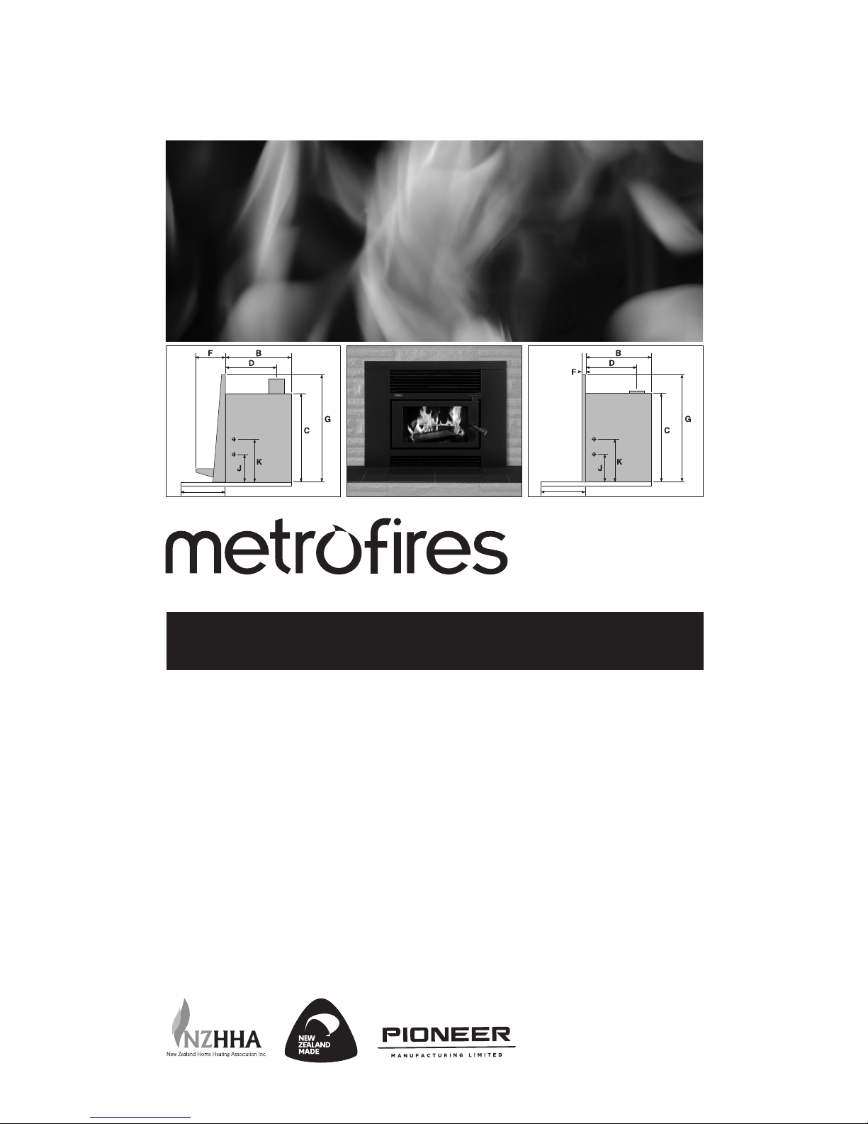
Insert Wood Fires
Wood Fire Installation & Owner’s Operation Manual
360MM
170MM
360MM
170MM
19 Oropuriri Road // New Plymouth 4312
info@metrofires.co.nz // www.metrofires.co.nz
10/17 © PIONEER MANUFACTURING LTD
2
Assembling your Metro wood fire
Metro insert fires are tested to comply with AS/NZS 2918:2001 incorporating
Appendix ‘E’ when installed in accordance with this manual. Please ensure
you are fully conversant with this relevant standard and the contents of this
manual. Correct installation is critical to the safe operation and performance
of this wood fire.
Please take particular note of the following:
• ECO Metro’s should be installed with a Metro ECO flue system which
has been developed to enhance the performance of Metro wood fires.
A minimum length of 4.1 metres of 150mm diameter is required. Any
alternative flue system must have a minimum flue pipe length of 4.1
metres of 150mm diameter flue pipe & have been tested to
AS/NZS2918:2001
• All flue joints must be sealed and riveted in three points with stainless
steel or monel rivets; the bottom of the flue in particular MUST be fully
sealed into the flue outlet of the Metro wood fire and secured with the
bolt & nut as supplied in the component kit
• The 150mm flue pipe must be fully encased to the underneath of the
flashing cone, from above the chimney breast. (there must not be any
150mm flue pipe exposed)
• Ensure a fibreglass seal is placed between the outer cabinet and the
masonry to prevent air from within the room being drawn into the
chimney cavity
• In New Zealand, the Metro Insert must be bolted securely to the base of
the chimney cavity to comply with the seismic restraint provisions of
AS/NZS2918.2001
• The Trend fascia is coated in vitreous enamel and the Smart fascia is
available in both vitreous enamel and metallic black high temperature
paint finish. Take care during assembly and when lifting and fitting the
fascia that you do not damage the vitreous enamel coating. Any surface
damage to the paint finish Smart fascia can be repaired with the use of
Pioneer high temperature paint.
• DO NOT lift the Insert fascia with your fingers under the louvre’s.
• WE HIGHLY RECOMMEND YOU READ THIS ENTIRE
MANUAL AS INCORRECT OPERATION, MISUSE AND/OR
LACK OF MAINTENANCE WILL VOID THE WARRANTY
• The appliance and flue-system shall be installed in accordance
with AS/NZS2918 and the appropriate requirements of the relevant
building code or codes
• Any modification of the appliance that has not been approved in
writing by the testing authority is considered to be in breach of the
approval granted for compliance with AS/NZS4013 and will void
the warranty
• The appliance must be installed correctly. We recommend a
competent and suitably qualified NZHHA installer
WARNING! Important Information
• Mixing of appliance or flue-system components from different
sources or modifying the dimensional specification or components
may result in hazardous conditions. Where such action is considered,
the manufacturer should be consulted in the first instance
• Do not install a Metro fire if there is any sign of visible damage to
the product
• This appliance must be regularly maintained.
• Use authorised Metro replacement parts only. The use of
unauthorised parts may void the warranty
• This manual MUST be left with the home owner
CAUTION! Important Information
All Metro Insert wood fires are packed in two heavy-duty cartons. The Insert
firebox is supplied in a heavy duty palletised carton, this carton is clearly
labelled. The fascia and door are packaged inside a smaller separate
carton. This carton is also clearly labelled to show the colour and coating
finish of the fascia and door. Metro fascia’s are coated in either vitreous
enamel or high temperature paint. Having removed the packaging and
located this manual, familiarise yourself with the diagrams on pages 3 & 4,
and proceed as detailed.
Note: The Metro carton shows the model Metro you are about to install,
enabling you to select the appropriate model’s assembly instructions.
ECO Insert Fan (ECO Trend Insert model only)
In all clean air zones, the Metro ECO Trend Insert must be installed with
Metro’s ECO Insert fan which is a single speed, thermostatically controlled
device. This fan must be permanently wired and therefore requires the
services of a registered electrician. Fitting instructions for the fan are
supplied with the fan module
Pre installation - Firebox cavity
Prior to installing your Metro insert firebox into a fireplace cavity, it is
important that specified clearances and other requirements are complied
with as follows:
• The chimney must be swept and checked for cracks and general
overall condition. If repairs are necessary, they must be carried out by
a suitably qualified person
• Check the cavity dimensions to ensure the fireplace insert will fit. It is
usually necessary to remove fire bricks from the lower fireplace cavity
• The base of the fireplace cavity on which the Metro fireplace insert will
rest must be level. If it is not, it should be levelled using mortar
• If an ash removal door exists in the base of the fireplace cavity it should
be sealed shut to prevent air entering the cavity
• If a timber or combustible mantelshelf exists above the fireplace
opening, it should be a minimum distance above the top of the Metro’s
fascia. If less than the minimum specified, a deflector or heat shield
will be required to be fitted under the mantelshelf or to the top of
the fascia using the relevant detail as set out in AS/NZS 2918:2001.
Mantle clearances are detailed on page 5.

3
Assembling your Metro wood fire
Metro Insert firebox
• Remove from within the firebox the plastic bag containing
the bolt kit, two firebricks wrapped in a cardboard wrapper
and then the top baffle assembly
• A ‘spacer’ washer has been pre-fitted and taped to the top
door hinge pin on the left hand side of the firebox (Refer
Inset A) remove this tape
• Remove the ‘cabinet top’ which is packed inverted on top
of the firebox and fit it into position over the cabinet sides
as detailed in Diagram 1. Ensure the rear edge is fitted
correctly as shown Diagram 1, Inset ‘B’, the rear edge of
the cabinet top must fit into the slot provided. Lift the front
to the highest available position and using two of the self
tapping screws from the plastic bag, secure the cabinet top
in place taking care to not damage the insulation blanket.
Note: This panel can be fitted at two height’s. If the height of
the fireplace opening will allow, fit the cabinet top in the higher
position, fit screws from inside the cabinet facing out.
• Ensure the insulating blanket is in position on the top of the
cabinet and remains in a sound condition
• Remove the four speed clip nuts from the plastic bag
and fit them to the holes provided in the front edge of the
cabinet as shown in Diagrams 1 and 1A
• Next you need to fit the top baffle.
All insert models feature a two piece top baffle which locates
onto six lugs provided on the side walls of the firebox’s upper
chamber, as detailed in Diagram 2 on page 4. The rear baffle
section is 6mm folded steel and has a central locating pin fitted
to its front top surface. Fit this rear baffle through the door
opening and into position in the upper chamber of the firebox.
It is supported on the rear four support lugs and must be hard
back against the rear wall of the firebox with the central locating
pin facing up and towards the front.
Next, locate the front baffle which is a combination baffle
comprising of a 6mm steel plate with a promet (white board)
front extension. Fit this baffle through the door opening and
into position, ensuring the hole provided on its rear edge is
positioned over the locating pin fitted to the rear baffle.
Unwrap the two firebricks from the cardboard wrapper and fit
the side bricks to each side of the firebox. Location lugs are
fitted to the base and rear of the firebox to retain the side bricks
in position, refer to the relevant Diagram 2 on page 4.
(B)
Fascia
Cabinet Top
Speed Clip
(x4)
Insert
Cabinet
Air Control Knob
Handle
Fixing Points For
Seismic Restraint
Spindle
Diagram 1 - ECO & LTD Insert Firebox
(A)
Spacer Washer
Hinge Pin
(B)
Fascia
Cabinet Top
Speed Clip
(x4)
Insert
Cabinet
Air Control Knob
Handle
Fixing Points For
Seismic Restraint
Spindle
Diagram 1A - Smart Insert & LTD Smart Insert Firebox
(A)
Spacer Washer
Hinge Pin

4
Diagram 3
Bottom
Louvre
Ashlip
Door Carton
Diagram 3A
Bottom
Louvre
Ashlip
Trend fascia’s are supplied partly assembled, and require the ashlip and
bottom louvre to be fi tted as illustrated in Diagrams 3 and 3A below. To
assemble, proceed as follows: -
• On a large fl at, clean and soft surface (carpet fl oor) slide the fascia out
of the carton, front face down and remove the door which is packed
into a separate carton located in the centre of the fascia. Close the
fl aps of the fascia carton and lay the fascia front down on top of this
now empty carton
• Remove the two sections of tape securing the ashlip panel to the rear
face of the fascia as detailed in Diagram 3. Carefully lift the ashlip
panel away from the fascia and place it gently to one side
• Remove the four screw’s and bottom louvre as illustrated in Diagram 3.
• Reposition the ashlip into its fi nal position as illustrated in Diagram 3A
taking particular attention to ensure:
- The ashlip is the right way around
- Do not mark the coating on the ends of the ashlip panel as you
slide it into the fascia, you may need to slightly prise apart the
fascia side panels as you fi t the ashlip.
• Position the bottom louvre as illustrated in Diagram 3A and refi t the
four screws previously removed.
The fascia is now completely assembled and ready for installation. When
moving the fascia, hold it at both sides to avoid ‘twisting’ the fascia which
may cause the enamel to chip.
Assembling the fascia (Trend Insert models only)
Assembling your Metro wood fi re
Diagram 2 - Firebox brick and baffl e locations
Side brick
ECO Insert Firebox LTD Insert Firebox Smart Insert & LTD Smart Insert Firebox
Brick support lugsWetback
connections
Side brickBrick support lugsWetback
connections
Side brickBrick support lugsWetback
connections
Rear baffl eFront baffl e
Rear baffl eFront baffl e Rear baffl eFront baffl e

5
Floor protector requirements
Floor Protector Heights 0mm 10mm 15mm 20mm 25mm 30mm 35mm 40mm 41mm+
ECO Trend Insert - DIMENSION I 300mm minimum projection is required irrespective of the height of the floor protector
LTD Trend Insert - DIMENSION I 455mm 455mm 445mm 436mm 424mm 408mm 396mm 366mm 350mm
Smart Insert - DIMENSION I 395mm 371mm 371mm 353mm 353mm 332mm 332mm 312mm 312mm
LTD Smart Insert - DIMENSION I 395mm 371mm 371mm 353mm 353mm 332mm 332mm 312mm 312mm
Firebox Width
Firebox Depth
Firebox Height
Flue Centre
Fascia Width
Fascia Depth
Fascia Height
Minimum Floor
Protector Width
Minimum Floor
Protector Projection
Wetback In
Wetback Out
Mantel clearance
Insert & Built-In Dimensions (mm) A B C
D
E F G H I J K L
ECO Trend Insert 560 500 550 405 810 185 650 825 300 170 360 340
LTD Trend Insert 560 500 550 405 810 185 650 825 350 170 360 460
Smart Insert 560 495 550 405 890 30 672 825 312 130 325 475
LTD Smart Insert 560 495 550 405 890 30 672 825 312 130 325 475
Please note: All measurements detailed above exclude the 13mm insulating blanket.
Floor protector requirements
Metro fireplace inserts are designed to be installed directly onto a concrete
base. The floor protector is required to project in front of the Metro and
must extend a minimum of 200mm to each side of the door opening
making the minimum floor protector width 825mm.
The floor protector must project from behind the fascia the distance
specified (I) in the table below. Minimum projection is the distance from
the front of the wall lining (behind the fascia) to the front non combustible
point of the floor protector.
ECO Trend Insert
On properties less than 2 hectares, the ECO Trend Insert must be installed
with the single speed Metro thermo fan.
The ECO Trend Insert requires an ash-hearth floor protector with
recommended construction of tiles on 6mm thick non combustible board.
The minimum floor protector projection forward of the Metro is 300mm as
detailed in the table below. Any non-combustible material fixed directly to a
combustible floor is acceptable.
LTD Trend Insert
The LTD Trend Insert requires an insulating floor protector. The forward
projection is dependent on the height of the fireplace insert above the
combustible floor. The schedule of projections listed for heights of 0mm
to 41mm+ can be achieved by the thickness of the floor protector, raising
the Insert or a combination of the two. Recommended construction is tiled
eterpan with a combined thickness as detailed in the table below.
Smart Insert
The ECO Smart Insert requires an insulating floor protector with
recommended construction of tiles on 26mm thick eterpan or alternative
insulating material of equivalent insulation properties. The forward
projection detailed below (I) is dependent on the height of the fireplace
insert above the combustible floor.
LTD Smart Insert
The LTD Smart Insert requires an insulating floor protector with
recommended construction of tiles on 26mm thick eterpan or alternative
insulating material of equivalent insulation properties. The forward
projection detailed below (I) is dependent on the height of the fireplace
insert above the combustible floor.
Mantel clearance
A timber or combustible mantel shelf above the fireplace Insert opening
should be a minimum distance (L) above the top of the Metro’s fascia
as detailed in the table below. If the clearance is less than the minimum
specified, a deflector or heat shield will be required to be fitted under the
mantelshelf or to the top of the fascia using the relevant detail as set out in
AS/NZS 2918:2001.
ECO Trend & LTD Trend Insert
360MM
170MM
Smart Insert models
360MM
170MM
Refer table below
(Dimension I)
Refer table below
(Dimension I)
595mm
595mm
 Loading...