

Page 1
PIONEER CORPORATION 4-1, Meguro 1-chome, Meguro-ku, Tokyo 153-8654, Japan
PIONEER ELECTRONICS (USA) INC. P.O. Box 1760, Long Beach, CA 90801-1760, U.S.A.
PIONEER EUROPE NV Haven 1087, Keetberglaan 1, 9120 Melsele, Belgium
PIONEER ELECTRONICS ASIACENTRE PTE. LTD. 253 Alexandra Road, #04-01, Singapore 159936
PIONEER CORPORATION
2008
EJECT
POWER
STOP STOPREAR
DISC
1
USB
1
USB
2
DISC
2
EJECT
MEP-7000
MULTI ENTERTAINMENT PLAYER
TRACK SEARCH
CUE/LOOP
EJECT
TIME
A.CUE
IN/CUE
HOT LOOP
LOOP
RELOOP/EXIT
PITCH BEND
BROWSE MIX EFFECT UTILITY
MT
0
MASTER
TEMPO
TEMPO
6/10/16WIDE
OUT/ADJUST
FWD TEMPOREV
MEMORY CALL
SEARCH
QUE
J
O
G
B
R
E
A
K
S
C
R
A
T
C
H
TRACK SEARCH
CUE/LOOP
EJECT
TIME
A.CUE
IN/CUE
HOT LOOP
LOOP
RELOOP/EXIT
PITCH BEND
MT
0
MASTER
TEMPO
TEMPO
6/10/16WIDE
OUT/ADJUST
FWD TEMPOREV
MEMORY CALL
SEARCH
QUE
J
O
G
B
R
E
A
K
S
C
R
A
T
C
H
A
LOAD
B
MEP-7000
LOAD
MULTI ENTERTAINMENT PLAYER
CONTROL UNIT
DRIVE UNIT
MEP-7000
MULTI ENTERTAINMENT PLAYER
MEP-7000
THIS MANUAL IS APPLICABLE TO THE FOLLOWING MODEL(S) AND TYPE(S).
Model Type Power Requirement Remarks.
MEP-7000 KUCXJ AC 120 V
MEP-7000 WYXJ5 AC 220 V to 240 V
MEP-7000 TLFXJ AC 110 V to 240 V
MEP-7000 WAXJ5 AC 220 V to 240 V
ORDER NO.
RRV3719
: This product comprises a control unit (CU-V170) and a drive unit. Note that
a user should bring in both units for servicing.
For details, refer to "Important Check Points for good servicing".
T-ZZR JULY
2008 Printed in Japan
Page 2
1
This service manual is intended for qualified service technicians; it is not meant for the casual
do-it-yourselfer. Qualified technicians have the necessary test equipment and tools, and have been
trained to properly and safely repair complex products such as those covered by this manual.
Improperly performed repairs can adversely affect the safety and reliability of the product and may
void the warranty. If you are not qualified to perform the repair of this product properly and safely,
you should not risk trying to do so and refer the repair to a qualified service technician.
WARNING
This product contains certain electrical parts contain chemicals which are known to the State of California to cause cancer,
birth defects or other reproductive harm.
Health & Safety Code Section 25249.6 - Proposition 65
NOTICE
(FOR CANADIAN MODEL ONLY )
Fuse symbols (fast operating fuse) and/or (slow operating fuse) on PCB indicate that replacement parts must
be of identical designation.
REMARQUE
(POUR MODÈLE CANADIEN SEULEMENT)
Les symboles de fusible (fusible de type rapide) et/ou (fusible de type lent) sur CCI indiquent que les pièces
de remplacement doivent avoir la même désignation.
ANY MEASUREMENTS NOT WITHIN THE
LIMITS OUTLINED ABOVE ARE INDICATIVE
OF A POTENTIAL SHOCK HAZARD AND
MUST BE CORRECTED BEFORE RETURNING THE APPLIANCE TO THE CUSTOMER.
2. PRODUCT SAFETY NOTICE
Many electrical and mechanical parts in the appliance
have special safety related characteristics. These are
often not evident from visual inspection nor the
protection afforded by them necessarily can be obtained
by using replacement components rated for voltage,
wattage, etc. Replacement parts which have these
special safety characteristics are identified in this
Service Manual.
Electrical components having such features are
identified by marking with a on the schematics and
on the parts list in this Service Manual.
The use of a substitute replacement component which
does not have the same safety characteristics as the
PIONEER recommended replacement one, shown in the
parts list in this Service Manual, may create shock, fire,
or other hazards.
Product Safety is continuously under review and new
instructions are issued from time to time. For the latest
information, always consult the current PIONEER
Service Manual. A subscription to, or additional copies
of, PIONEER Service Manual may be obtained at a
nominal charge from PIONEER.
(FOR USA MODEL ONLY)
1. SAFETY PRECAUTIONS
The following check should be performed for the
continued protection of the customer and service
technician.
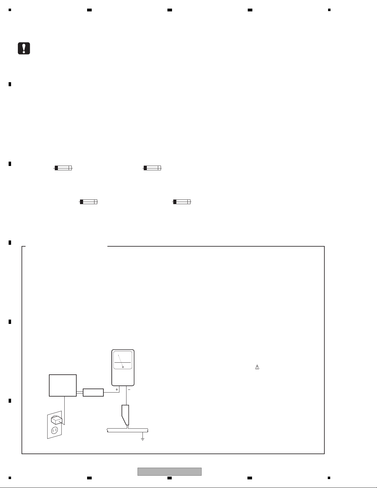
LEAKAGE CURRENT CHECK
Measure leakage current to a known earth ground
(water pipe, conduit, etc.) by connecting a leakage
current tester such as Simpson Model 229-2 or
equivalent between the earth ground and all exposed
metal parts of the appliance (input/output terminals,
screwheads, metal overlays, control shaft, etc.). Plug
the AC line cord of the appliance directly into a 120V
AC 60 Hz outlet and turn the AC power switch on. Any
current measured must not exceed 0.5 mA.
Device
under
test
Leakage
current
tester
Earth
ground
Reading should
not be above
0.5 mA
Also test with
plug reversed
(Using AC adapter
plug as required)
Test al l
exposed metal
surfaces
AC Leakage Test
2 3 4
SAFETY INFORMATION
A
B
C
D
E
F
2
1
2 3 4
MEP-7000
Page 3
5
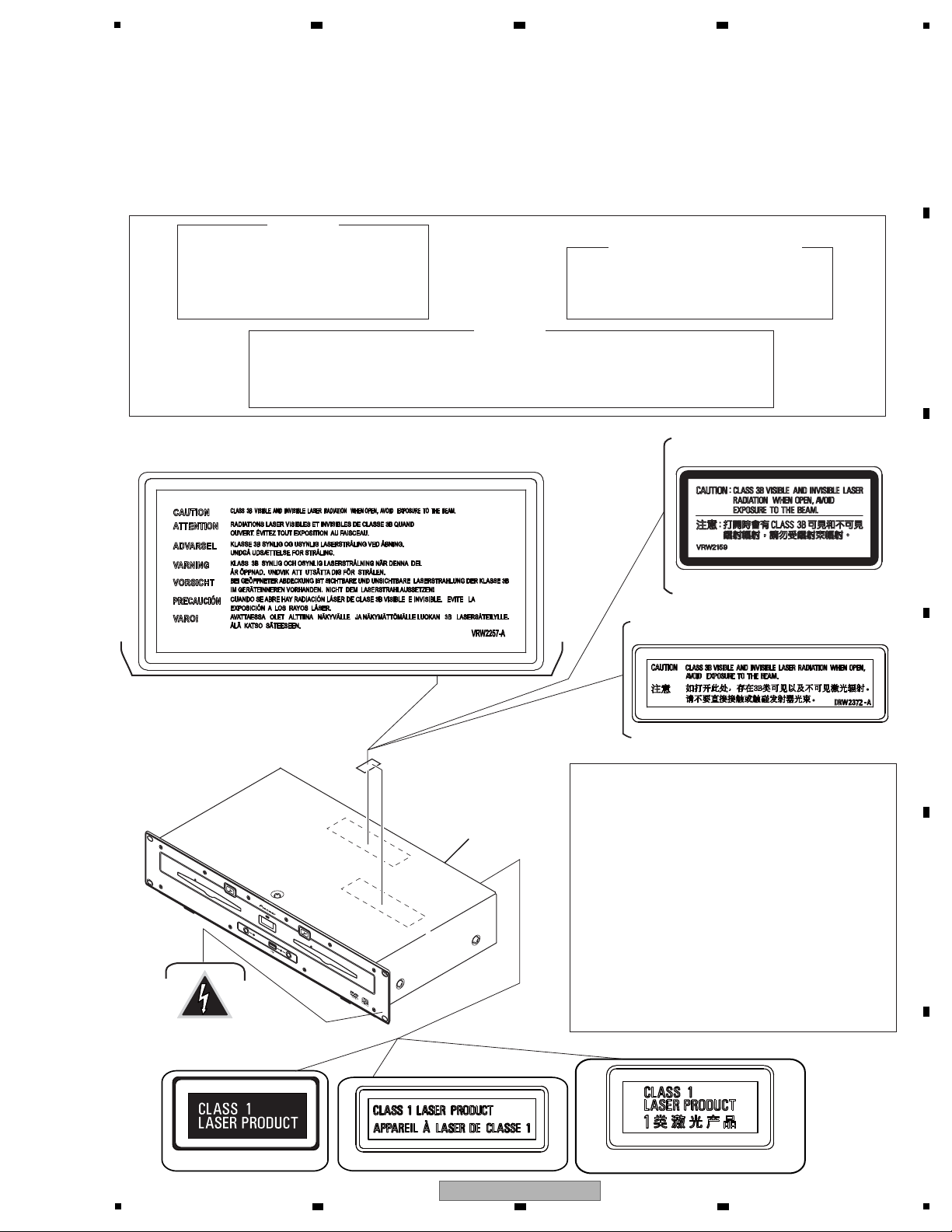
IMPORTANT
THIS PION EER APPARATUS CON TAINS
LASER OF CLASS 1.
SERVICING OPERATION OF THE APPARATUS
SHOULD BE DON E BY A SPECIALLY
INSTRUCTED PERSON.
Additional Laser Caution
For TLFXJ
For WYXJ5 and KUCXJ
For WAXJ5
For TLFXJ
(VRW2257)
(DRW1975)
(VRW2159)
For WAXJ5
(DRW2372)
LASER DIODE CHARACTERISTICS
FOR DVD : MAXIMUM OUTPUT POWER : 5 mW
WAVELENGTH : 650 nm
FOR CD : MAXIMUM OUTPUT POWER : 7 mW
WAVELENGTH : 780 nm
∗ : See page 160, 161, 164, 165.
1. Laser Interlock Mechanism
The position of the switch (S4400,S4500) for detecting loading
completion is detected by the system microprocessor, and the
design prevents laser diode oscillation when the switch is not
in LPS1 terminal side (when the mechanism is not clamped
and LPS1 signal is high level.)
Thus, the interlock will no longer function if the switch is
deliberately set to LPS1 terminal side. (if LPS1 signal is low
level ).
In the SERVICE MODE∗ the interlock mechanism will not
function.
Laser diode oscillation will continue, if pin 3 (pin 5) of
AN22022A (IC102, IC902) on the SRV1,SRV2 Assy is
connected to GND, or else the terminals of Q102
(Q103), Q902(Q903) are shorted to each other (fault
condition).
2. When the cover is opened, close viewing of the objective lens
with the naked eye will cause exposure to a Class 1 laser
beam.
WARNING !
THE AEL (ACCESSIBLE EMISSION LEVEL) OF THE LASER POWER OUTPUT IS LESS THAN CLASS 1
BUT THE LASER COMPONENT IS CAPABLE OF EMITTING RADIATION EXCEEDING THE LIMIT FOR
CLASS 1.
A SPECIALLY INSTRUCTED PERSON SHOULD DO SERVICING OPERATION OF THE APPARATUS.
For WYXJ5 and KUCXJ
Rear Panel
LABEL CHECK
Printed on the Rear Panel
Printed on the Rear Panel
Printed on the Rear panel
For KUCXJ type Only
EJECT
POWER
S
TO
P
S
T
O
P
REAR
DIS
C
1
U
S
B
1
U
S
B
2
DIS
C
2
EJEC
T
MEP-7000
MU
L
TI ENTE
R
TAINMENT PL
AY
E
R
This product contains mercury. Disposal of this material may be regulated due to environmental
considerations. For disposal or recycling information, please contact your local authorities or the
Electronics Industries Alliance: www.eiae.org.
The backlighting lamp of LCD in this equipment contains mercury. Disposal of this material may
be regulated due to environmental considerations according to Local, State or Federal Laws.
For disposal or recycling information, please contact your local authorities or the Electronics
Industries Alliance: www.eiae.org
6 7 8
A
B
C
D
E
F
5
MEP-7000
6 7 8
3
Page 4
1
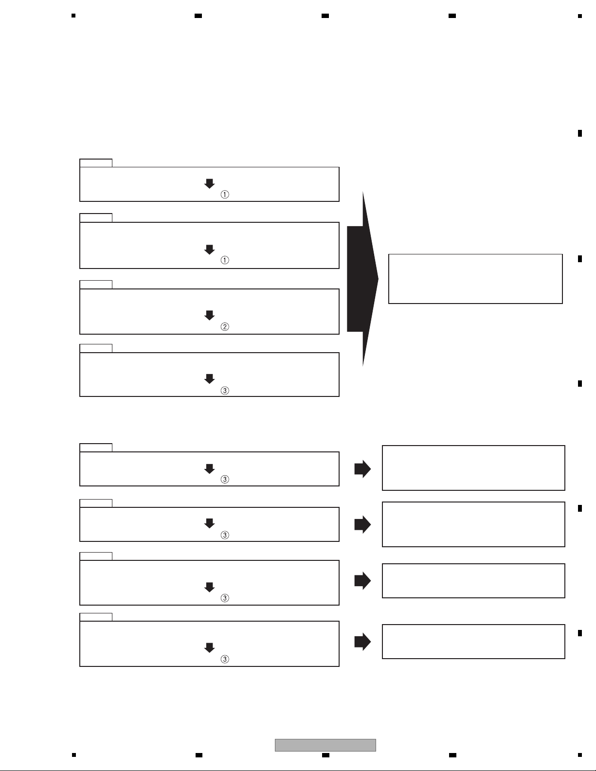
[Important Check Points for Good Servicing]
In this manual, procedures that must be performed during repairs are marked with the below symbol.
Please be sure to confirm and follow these procedures.
1. Product safety
Please conform to product regulations (such as safety and radiation regulations), and maintain a safe servicing environment by
following the safety instructions described in this manual.
1 Use specified parts for repair.
Use genuine parts. Be sure to use important parts for safety.
2 Do not perform modifications without proper instructions.
Please follow the specified safety methods when modification(addition/change of parts) is required due to interferences such as
radio/TV interference and foreign noise.
3 Make sure the soldering of repaired locations is properly performed.
When you solder while repairing, please be sure that there are no cold solder and other debris.
Soldering should be finished with the proper quantity. (Refer to the example)
4 Make sure the screws are tightly fastened.
Please be sure that all screws are fastened, and that there are no loose screws.
5 Make sure each connectors are correctly inserted.
Please be sure that all connectors are inserted, and that there are no imperfect insertion.
6 Make sure the wiring cables are set to their original state.
Please replace the wiring and cables to the original state after repairs.
In addition, be sure that there are no pinched wires, etc.
7 Make sure screws and soldering scraps do not remain inside the product.
Please check that neither solder debris nor screws remain inside the product.
8 There should be no semi-broken wires, scratches, melting, etc. on the coating of the power cord.
Damaged power cords may lead to fire accidents, so please be sure that there are no damages.
If you find a damaged power cord, please exchange it with a suitable one.
9 There should be no spark traces or similar marks on the power plug.
When spark traces or similar marks are found on the power supply plug, please check the connection and advise on secure
connections and suitable usage. Please exchange the power cord if necessary.
a Safe environment should be secured during servicing.
When you perform repairs, please pay attention to static electricity, furniture, household articles, etc. in order to prevent injuries.
Please pay attention to your surroundings and repair safely.
2. Adjustments
To keep the original performance of the products, optimum adjustments and confirmation of characteristics within specification.
Adjustments should be performed in accordance with the procedures/instructions described in this manual.
4. Cleaning
For parts that require cleaning, such as optical pickups, tape deck heads, lenses and mirrors used in projection monitors, proper
cleaning should be performed to restore their performances.
3. Lubricants, Glues, and Replacement parts
Use grease and adhesives that are equal to the specified substance.
Make sure the proper amount is applied.
5. Shipping mode and Shipping screws
To protect products from damages or failures during transit, the shipping mode should be set or the shipping screws should be
installed before shipment. Please be sure to follow this method especially if it is specified in this manual.
A
2 3 4
B
C
D
E
F
4
1
MEP-7000
2 3 4
Page 5

5
6 7 8
CONTENTS
SAFETY INFORMATION.......................................................................................................................................................... 2
1. SERVICE PRECAUTIONS....................................................................................................................................................7
1.1 NOTES ON SOLDERING............................................................................................................................................... 7
1.2 BACKUP AND RESTORING OF USER DATA................................................................................................................7
1.3 NOTE ON ENTRAPMENT OF DIRT IN THE DISPLAY PANEL .....................................................................................8
1.4 REPAIR OF THE SJACK ASSY......................................................................................................................................8
1.5 CABLE DRESSING OF THE DRIVE UNIT.....................................................................................................................9
1.6 REASSEMBLING OF THE CONTROL UNIT ............................................................................................................... 14
2. SPECIFICATIONS...............................................................................................................................................................18
2.1 ACCESSORIES............................................................................................................................................................18
2.2 SPECIFICATIONS ........................................................................................................................................................ 19
2.3 REGARDING PLAYABLE DISCE AND FILES..............................................................................................................21
2.4 PANEL FACILITIES.......................................................................................................................................................25
3. BASIC ITEMS FOR SERVICE ............................................................................................................................................ 29
3.1 CHECK POINTS AFTER SERVICING ......................................................................................................................... 29
3.2 PCB LOCATIONS .........................................................................................................................................................30
3.3 JIGS LIST .....................................................................................................................................................................32
4. BLOCK DIAGRAM .............................................................................................................................................................. 34
4.1 OVERALL WIRING (CONTROL UNIT).........................................................................................................................34
4.2 OVERALL WIRING (DRIVE UNIT) ...............................................................................................................................36
4.3 BLOCK DIAGRAM........................................................................................................................................................ 38
5. DIAGNOSIS ........................................................................................................................................................................48
5.1 POWER ON SEQUENCE.............................................................................................................................................48
5.2 CONFIRMATION OF COMMUNICATION WITH THE PC VIA USB .............................................................................55
5.3 TROUBLE SHOOTING .................................................................................................................................................56
5.4 DEFECT JUDGMENT OF THE PICKUP ASSY...........................................................................................................85
6. SERVICE MODE.................................................................................................................................................................86
6.1 TABLE OF CONTENTS ................................................................................................................................................86
6.2 SERVICE MODE FOR THE DRIVE UNIT ....................................................................................................................87
6.3 SERVICE MODE FOR THE CONTROL UNIT..............................................................................................................97
6.4 ERROR CODE LIST................................................................................................................................................... 103
6.5 STATUS LEDS ............................................................................................................................................................ 104
7. DISASSEMBLY .................................................................................................................................................................108
7.1 DRIVE UNIT ...............................................................................................................................................................108
7.2 CONTROL UNIT......................................................................................................................................................... 113
8. EACH SETTING AND ADJUSTMENT..............................................................................................................................115
8.1 CONFIRMATION MODE AND ADJUSTMENT METHOD FOR LOAD ON THE JOG DIAL .......................................115
8.2 RESET OF DVD/CD DRIVE DATA..............................................................................................................................
8.3 UPDATING/RECOVERY OF FIRMWARE...................................................................................................................117
8.4 MANUAL INPUT OF DVD/CD DRIVE DATA...............................................................................................................132
9. EXPLODED VIEWS AND PARTS LIST............................................................................................................................. 134
9.1 PACKING SECTION ...................................................................................................................................................134
: DRIVE UNIT
9.2 EXTERIOR SECTION ................................................................................................................................................ 136
9.3 FRONT PANEL SECTION ..........................................................................................................................................138
9.4 SLOT-IN MECHA SECTION .......................................................................................................................................140
: CONTROL UNIT
9.5 EXTERIOR SECTION ................................................................................................................................................ 142
9.6 CONTROL PANEL SECTION..................................................................................................................................... 144
10. SCHEMATIC DIAGRAM..................................................................................................................................................146
: DRIVE UNIT
10.1 SMAIN ASSY (1/5) ................................................................................................................................................... 146
10.2 SMAIN ASSY (2/5) ................................................................................................................................................... 148
10.3 SMAIN ASSY (3/5) ................................................................................................................................................... 150
10.4 SMAIN ASSY (4/5) ................................................................................................................................................... 152
10.5 SMAIN ASSY (5/5) ................................................................................................................................................... 154
10.6 EJTB ASSY ..............................................................................................................................................................156
10.7 FSWB ASSY............................................................................................................................................................. 157
10.8 SJACK ASSY............................................................................................................................................................158
10.9 SRV1 ASSY .............................................................................................................................................................. 160
10.10 SLMB1 ASSY .........................................................................................................................................................162
10.11 USBB ASSY ...........................................................................................................................................................163
10.12 SRV2 ASSY............................................................................................................................................................164
10.13 SLMB2 ASSY .........................................................................................................................................................166
10.14 ACIN ASSY............................................................................................................................................................. 167
MEP-7000
5
6 7 8
116
5
A
B
C
D
E
F
Page 6

1
2 3 4
10.15 POWER SUPPLY UNIT...........................................................................................................................................168
: CONTROL UNIT
10.16 NMAIN ASSY (1/5) .................................................................................................................................................170
10.17 NMAIN ASSY (2/5) .................................................................................................................................................172
A
10.18 NMAIN ASSY (3/5) .................................................................................................................................................174
10.19 NMAIN ASSY (4/5) .................................................................................................................................................176
10.20 NMAIN ASSY (5/5) .................................................................................................................................................178
10.21 NJACK ASSY..........................................................................................................................................................180
10.22 RENC ASSY ...........................................................................................................................................................182
10.23 DJACK ASSY..........................................................................................................................................................183
10.24 DISP ASSY.............................................................................................................................................................184
10.25 JOGT ASSY............................................................................................................................................................186
10.26 JOGR ASSY ...........................................................................................................................................................187
10.27 OELB ASSY............................................................................................................................................................188
10.28 VOLTAGES..............................................................................................................................................................189
B
10.29 WAVEFORMS.........................................................................................................................................................197
10.30 INFORMATION ON FUNCTIONS OF IC TERMINALS...........................................................................................237
11. PCB CONNECTION DIAGRAM ......................................................................................................................................253
: DRIVE UNIT
11.1 SMAIN ASSY............................................................................................................................................................254
11.2 EJTB and FSWB ASSYS..........................................................................................................................................258
11.3 SJACK ASSY ............................................................................................................................................................260
11.4 SRV1 ASSY ..............................................................................................................................................................262
11.5 SLMB1 ASSY............................................................................................................................................................264
11.6 USBB ASSY..............................................................................................................................................................265
11.7 SRV2 ASSY ..............................................................................................................................................................266
11.8 SLMB2 ASSY............................................................................................................................................................268
C
11.9 ACIN ASSY...............................................................................................................................................................269
: CONTROL UNIT
11.10 NMAIN ASSY..........................................................................................................................................................270
11.11 NJACK, RENC and DJACK ASSYS........................................................................................................................274
11.12 DISP ASSY.............................................................................................................................................................276
11.13 JOGT, JOGR and OELB ASSYS ............................................................................................................................278
12. PCB PARTS LIST ............................................................................................................................................................280
D
E
F
6
1
2 3 4
MEP-7000
Page 7

5
• For environmental protection, lead-free solder is used on the printed circuit boards mounted in this unit.
Be sure to use lead-free solder and a soldering iron that can meet specifications for use with lead-free solders for repairs
accompanied by reworking of soldering.
• Compared with conventional eutectic solders, lead-free solders have higher melting points, by approximately 40 ºC.
Therefore, for lead-free soldering, the tip temperature of a soldering iron must be set to around 373 ºC in general, although
the temperature depends on the heat capacity of the PC board on which reworking is required and the weight of the tip of
the soldering iron.
Do NOT use a soldering iron whose tip temperature cannot be controlled.
Compared with eutectic solders, lead-free solders have higher bond strengths but slower wetting times and higher melting
temperatures (hard to melt/easy to harden).
The following lead-free solders are available as service parts:
• Parts numbers of lead-free solder:
GYP1006 1.0 in dia.
GYP1007 0.6 in dia.
GYP1008 0.3 in dia.
Before repair, back up user data, following the backup procedures shown below.
After repair, restore the user data backed up before repair, following the restoration procedures shown below.
Backup procedures
Copy cue/loop points of a disc stored in the built-in memory of the product and the playlist that is produced by the user to a
USB storage device. Before starting the backup procedures, make sure that no disc nor USB storage device is inserted.
1. Press the UTILITY key.
2. Press the function GENERAL key.
3. Select BACKUP MODE, by turning the rotary selector, then press the Select Down key or the rotary selector.
4. Select “Write to USB,” by turning the rotary selector, then press the rotary selector.
5. The message “Connect a USB storage device to the USB port” is displayed. Insert a USB storage device.
6. Data copying starts.
When “Done” is displayed and the UTILITY screen is restored, data copying is complete.
Note:
A file named “BACKUP.BIN” of approx. 1.3 MBytes is created in the root directory of the USB storage device.
Restoring procedures
The user data copied to the USB storage device are written to the built-in memory of this product.
1. Press the UTILITY key.
2. Press the function GENERAL key.
3. Select BACKUP MODE, by turning the rotary selector, then press the Select Down key or the rotary selector.
4. Select “Read from USB,” by turning the rotary selector, then press the rotary selector.
5. The message “Connect a USB storage device to the USB port” is displayed. Insert a USB storage device.
6. Data reading starts.
When “Done” is displayed and the UTILITY screen is restored, data reading is complete.
Note:
The data previously stored in the built-in memory are completely erased, and the data in the USB storage device will be
copied.
6 7 8
1. SERVICE PRECAUTIONS
1.1 NOTES ON SOLDERING
1.2 BACKUP AND RESTORING OF USER DATA
A
B
5
6 7 8
MEP-7000
C
D
E
F
7
Page 8

1
As the panels for the center display and controller displays are of transparent type, entrapment of dirt in the panel is highly
visible. Be careful not entrap dirt while reassembling, and check that there is no dirt entrapped after reassembling.
Before repairing the SJACK Assy, check its part number.
If the part number is “DWX2710,” replace it with a “DWX2896” instead of repairing it.
D
SJACK ASSY
2 3 4
1.3 NOTE ON ENTRAPMENT OF DIRT IN THE DISPLAY PANEL
A
1.4 REPAIR OF THE SJACK ASSY
B
1
C
CN11
4.DGND
1
3.D+
KN10
2.D-
DGND
1.V+5USB1D
J11
J30
FGND
C12
JA15
41
J43
DGND
SJACK
V+5DETD
J48
DWX2710-
FGND
J39
4.DGND3.D+
2.D- 1.V+5DETD
D
JA16
1
4
J35
FGND
1
DGND
J22
2
3
1
CN11
4.DGND
1
3.D+
KN10
2.D-
DGND
1.V+5USB1D
J11
J30
FGND
C12
JA15
41
J43
DGND
SJACK
JA16
1
4
J48
J35
FGND
1
DGND
J22
4.DGND3.D+
2
3
DWX2896-
V+5DETD
FGND
J39
2.D- 1.V+5DETD
E
F
8
1
2 3 4
MEP-7000
Page 9
5
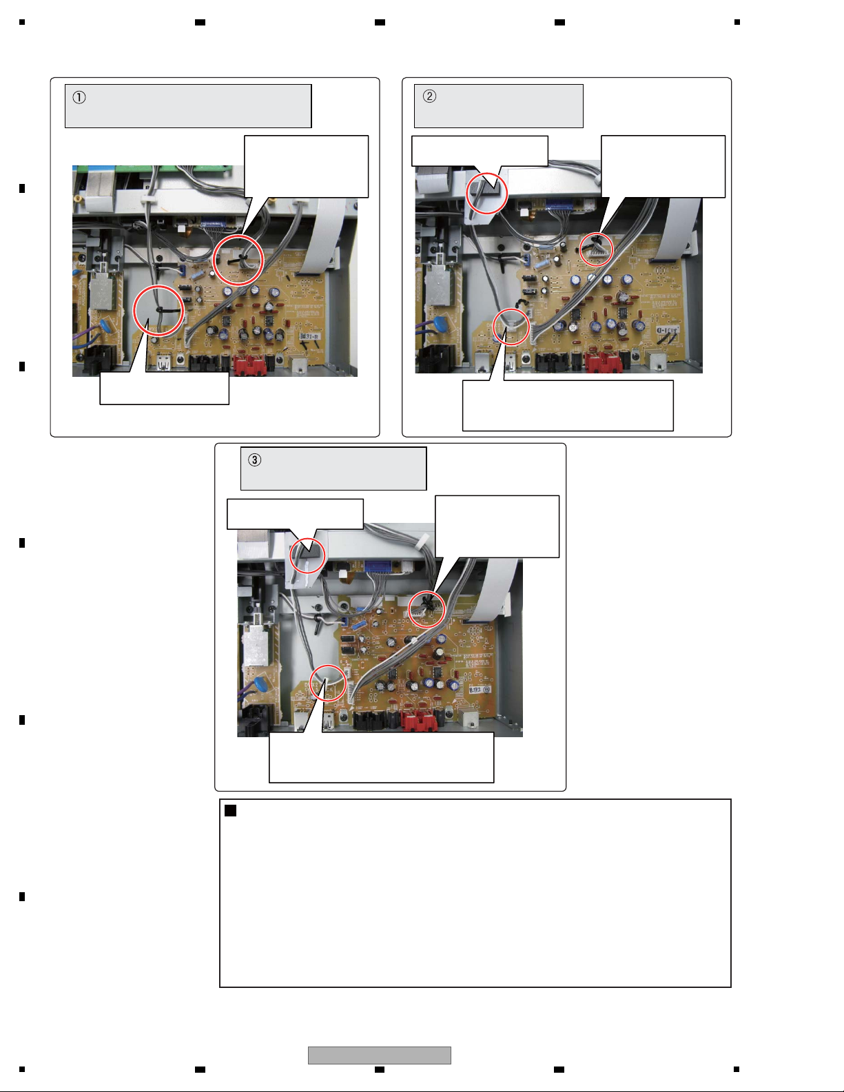
How you dress the cables connected to the SJACK Assy greatly affects the sound quality from the unit. During
disassembly and reassembly of the drive unit, be careful of cable dressing. At the end of reassembly, be sure to
check that the cable dressing is performed as shown below.
For performance improvement, cable dressing methods have been changed several times in the middle of mass
production of this product.
During cable dressing of this product, be careful of the following points:
CASE 1
[1] When cables are disconnected from the SJACK Assy
[2] When the SJACK Assy is replaced
It is essential that the cables be dressed as
they originally were.
When the DWX2710 is replaced with the DWX2896 :
See Fig .
Parts to be added during servicing :
FFC guard (DEC2586) &
Shield Sheet (DEC3151) &
Locking Mini Clamp (DEC2439)
Parts to be added during servicing :
FFC guard (DEC2586) &
Shield Sheet (DEC3151) &
Locking Mini Clamp (DEC2439)
Parts to be added during servicing :
Locking Mini Clamp (DEC2439)
Parts to be added during servicing :
None
When the DWX2896 in the initial cable dressing state is replaced :
See Fig .
When cables are disconnected from the DWX2710 :
See Fig .
When cables in the initial dressing state are disconnected from
the DWX2896 :
See Fig .
When cables in the temporary dressing state are disconnected
from the DWX2896 :
See Fig .
When cables in the permanent dressing state are disconnected
from the DWX2896 :
See Fig .
CASE 2
CASE 3
CASE 4
CASE 5
CASE 6
When the DWX2896 in the temporary cable dressing state is
replaced :
See Fig .
CASE 7
When the DWX2896 in the permanent cable dressing state is
replaced :
See Fig .
CASE 8
6 7 8
1.5 CABLE DRESSING OF THE DRIVE UNIT
A
B
C
D
E
5
MEP-7000
6 7 8
F
9
Page 10
1
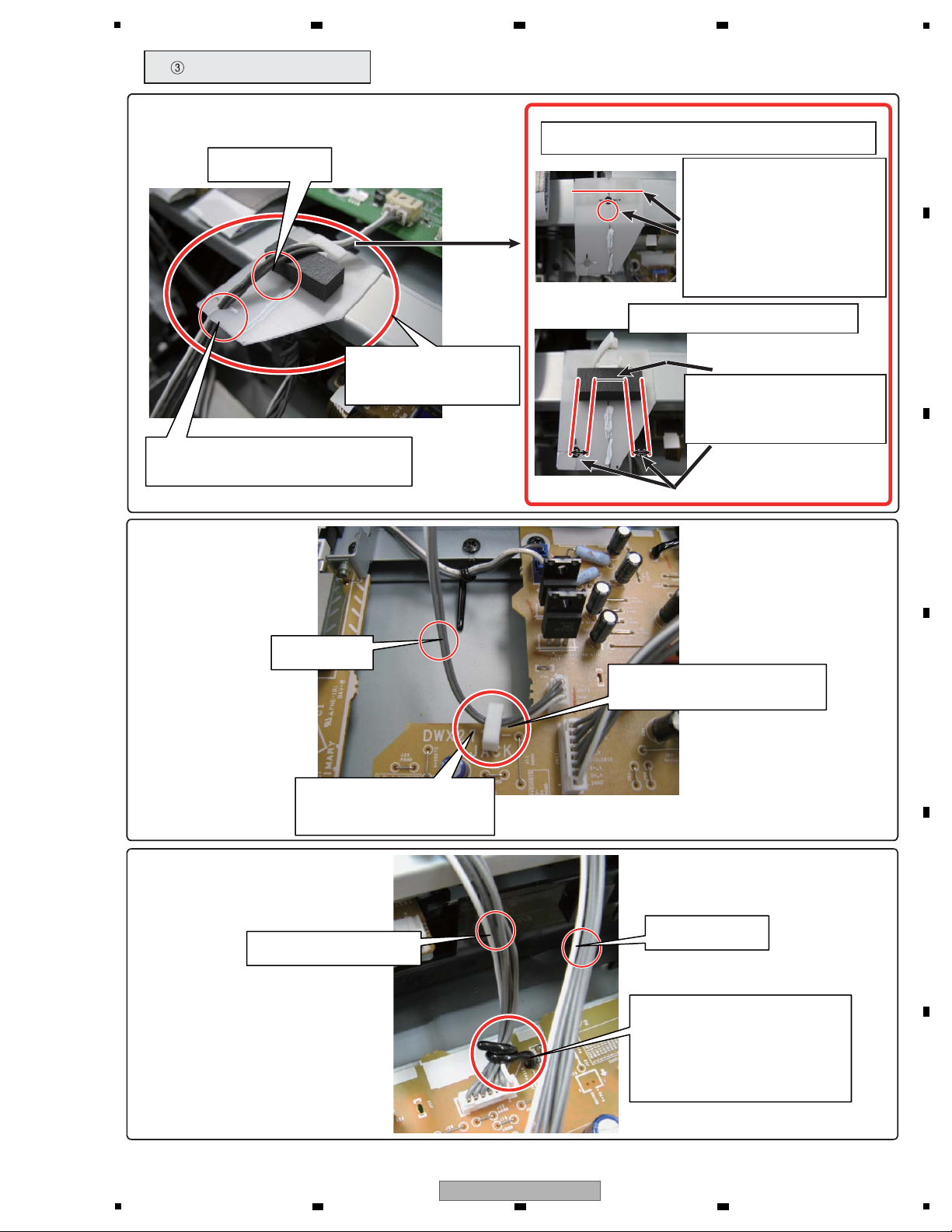
Tie the D-OUT cables
with the PCB binder.
Pass the D-OUT cables through the
clamp that has been attached to
the board.
Fix the D-OUT cables with the Locking
Mini Clamp that has been inserted in
the hole of the board.
Tie the cables for
analog signals
with the PCB binder
located on the left.
Tie the cables for
analog signals
with the PCB binder
located on the left.
Tie the cables for
analog signals
with the PCB binder
located on the right.
Add the Shield Sheet
and FFC guard.
Add the Shield Sheet
and FFC guard.
: Initial dressing
(for the DWX2710 and DWX2896)
: Temporary dressing
(for the DWX2896)
: Permanent dressing
(for the DWX2896)
[3] Differences in Cable Dressing States
Notes
1: Before replacing the Assy, be sure to check the current cable dressing.
2: Depending on the dressing state, some additional parts may be required:
If the previous board is in the initial cable dressing state:
FFC guard (DEC2586), Shield Sheet (DEC3151) and Locking Mini Clamp (DEC2439)
If the previous board is in the temporary cable dressing state:
Locking Mini Clamp (DEC2439)
If the previous board is in the permanent cable dressing state:
No additional parts needed
3: Permanent cable dressing is possible with the Assy for service.
A
2 3 4
B
C
D
E
F
10
1
2 3 4
MEP-7000
Page 11

5
Regulator
D-OUT cables
USB cables
USB cables
Leave at least 10 mm.
Leave at least 5 mm.
Leave at least 10 mm.
D-OUT cables
SERVO cables
Cables for analog signals
Bind the cables for
analog signals and push
them downward so that
they are positioned as
far from the USB cables
as possible.
While dressing the cables,
be careful that the cables
for analog signals do not
touch the SLMB Assy.
Place the binder in
the upright position.
SLMB Assy
Leave at least 10 mm
between the D-OUT and
SERVO cables.
Leave at least 10 mm
between the D-OUT cables
and the regulator.
[4] Notes on Each Cable Dressing
Fig : Initial dressing
Leave at least 5 mm
between the D-OUT and
USB cables.
6 7 8
A
B
C
D
5
MEP-7000
6 7 8
E
F
11
Page 12

1
USB cables
Cables for analog signals
Push the cables for analog
signals downward so that
they are positioned as far
from the USB cables as
possible.
While dressing the cables,
be careful that the cables
for analog signals do not
touch the SLMB Assy.
SLMB Assy
D-OUT cables
Pass the D-OUT cables through the clamp.
Fig : Temporary cable dressing
How to attach the Shield Sheet and FFC guard
Add the Shield Sheet
(DEC3151) and
FFC guard (DEC2586).
Pass the D-OUT cables through
the slit of the Shield Sheet
1. Align the edge of the Shield
Sheet with that of the PCB
STAY Assy and the hole of the
Shield Sheet with that for the
locking mini clamp on the PCB
STAY Assy. Then paste the
Shield Sheet to the PCB STAY
Assy.
2. Attach the locking mini clamp.
D-OUT cables
3. Place the FFC guard in
contact with the clamp and
so that the clamp comes to
the middle of the FFC guard.
A
B
C
2 3 4
D
E
F
12
MEP-7000
1
2 3 4
Page 13
5
Fig : Permanent cable dressing
Insert the locking mini clamp
(DEC2439, additional part)
in the hole of the board.
D-OUT cables
Cables for analog signals
Pass the D-OUT cables
through the locking mini clamp.
Tie the cables for analog signals
with the PCB binder at the base.
Push the cables down toward
the board so that they are
positioned as far from
the USB cables as possible.
USB cables
How to attach the Shield Sheet and FFC guard
Add the Shield Sheet
(DEC3151) and
FFC guard (DEC2586).
Pass the D-OUT cables through
the slit of the Shield Sheet
1. Align the edge of the Shield
Sheet with that of the PCB
STAY Assy and the hole of the
Shield Sheet with that for the
locking mini clamp on the PCB
STAY Assy. Then paste the
Shield Sheet to the PCB STAY
Assy.
2. Attach the locking mini clamp.
D-OUT cables
3. Place the FFC guard in
contact with the clamp and
so that the clamp comes to
the middle of the FFC guard.
6 7 8
A
B
C
5
MEP-7000
6 7 8
D
E
F
13
Page 14
1
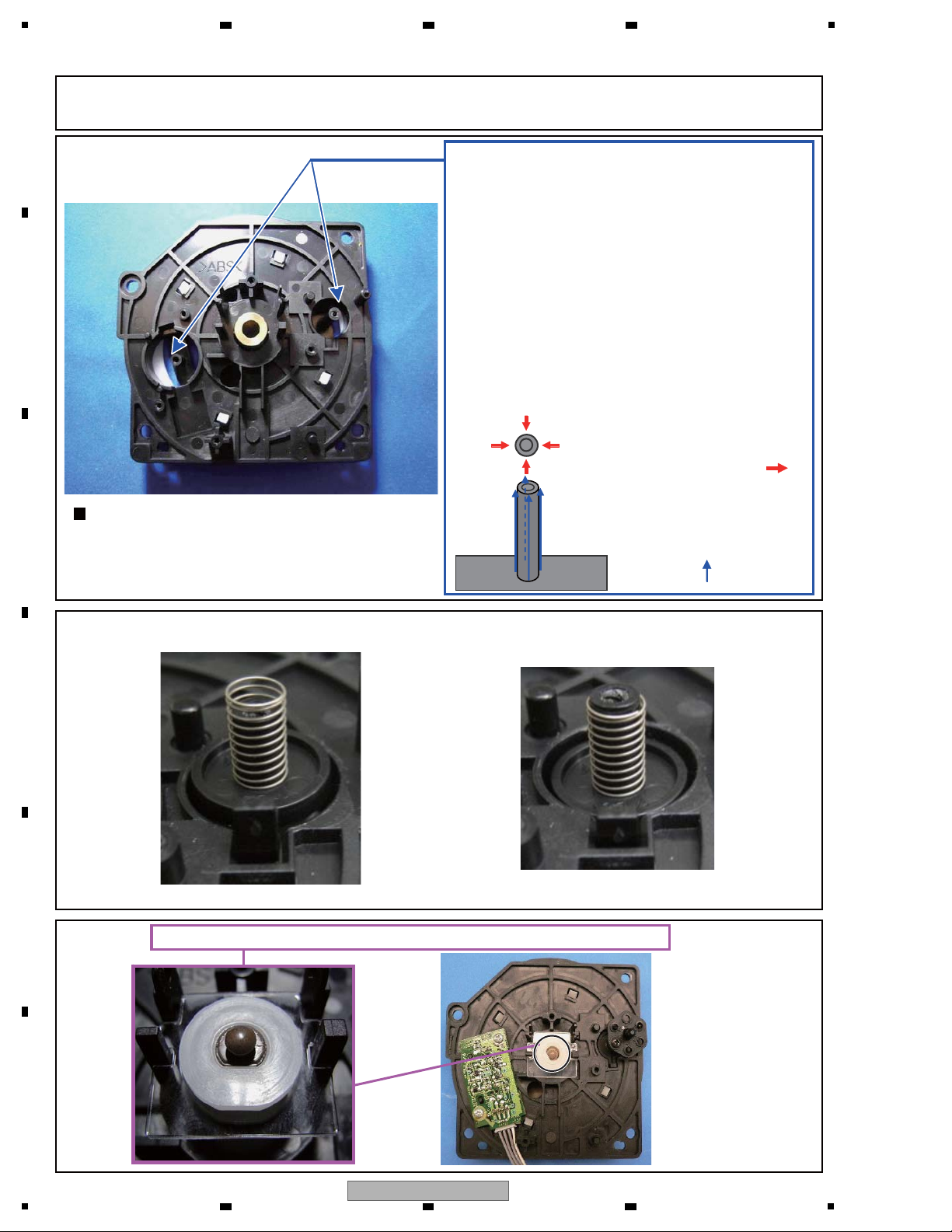
How to apply FL OIL is described below.
Make sure that the top end of the load spring is not higher than that of the shaft when it is inserted into the shaft. If it is,
turn the JOG dial a little so that the load gear and the gear of the JOG shaft will become properly engaged.
<Preparation>
Soak FL OIL into a sponge.
Dab a brush against the sponge to pick up oil.
Remove excess oil from the brush.
<Application of FL OIL>
1. Dab the brush against the sponge to pick up a little
oil with the brush.
2. With the brush, lightly apply oil from the base to the
tip of the shaft.
3. Apply oil from 4 directions, as shown below, at a time.
(NEVER replenish oil to the brush on the way.)
<Note>
1. NEVER apply oil more than 4 times to the shaft.
Avoid applying excess oil.
<TOP VIEW>
Apply oil from the 4 directions
indicated by the arrows ( ),
at a time.
<SIDE VIEW>
Apply oil from the base to the
tip of the shaft, as indicated by
the arrows ( ).
NGOK
Place the JOG smoother so that its convex surface faces the JOG smoother plate.
Note on gear insertion
When inserting the gear, do NOT forcibly push it.
Insert the gear while turning it slightly until it is properly
engaged.
After the JOG Assy is disassembled or JOG dial parts are replaced, be sure to measure the load on the JOG dial, as it may
have changed. (For details on how to measure the load on the JOG dial,
see “8.1 CONFIRMATION MODE AND ADJUSTMENT METHOD FOR LOAD ON THE JOG DIAL.”)
2 3 4
1.6 REASSEMBLING OF THE CONTROL UNIT
A
B
C
D
E
F
14
MEP-7000
1
2 3 4
Page 15

5
When reattaching the rear panel and panel base, be careful to properly position them.
The edge of the plate is disengaged.
NG
OK
Notes on replacement of the NMAIN Assy and LCD module
Remove the screw.
Remove the TFT shield.
Note: Engage the hooks to the slots when reassembling.
Remove the flexible cables.
Remove the screws. The NMAIN Assy
can be detached.
Remove the screws. The LCD module
can be detached.
Note: When reattaching the LCD module to the TFT holder,
engage the 4 hooks of the holder to the slots.
Note: Be careful that the aluminum sheet goes
above this level.
Fold the aluminum sheet.
Note: During detaching/reattaching
the LCD module, be careful not to apply excess
force to the 4 hooks of the TFT holder.
6 7 8
A
B
C
D
5
MEP-7000
6 7 8
E
F
15
Page 16
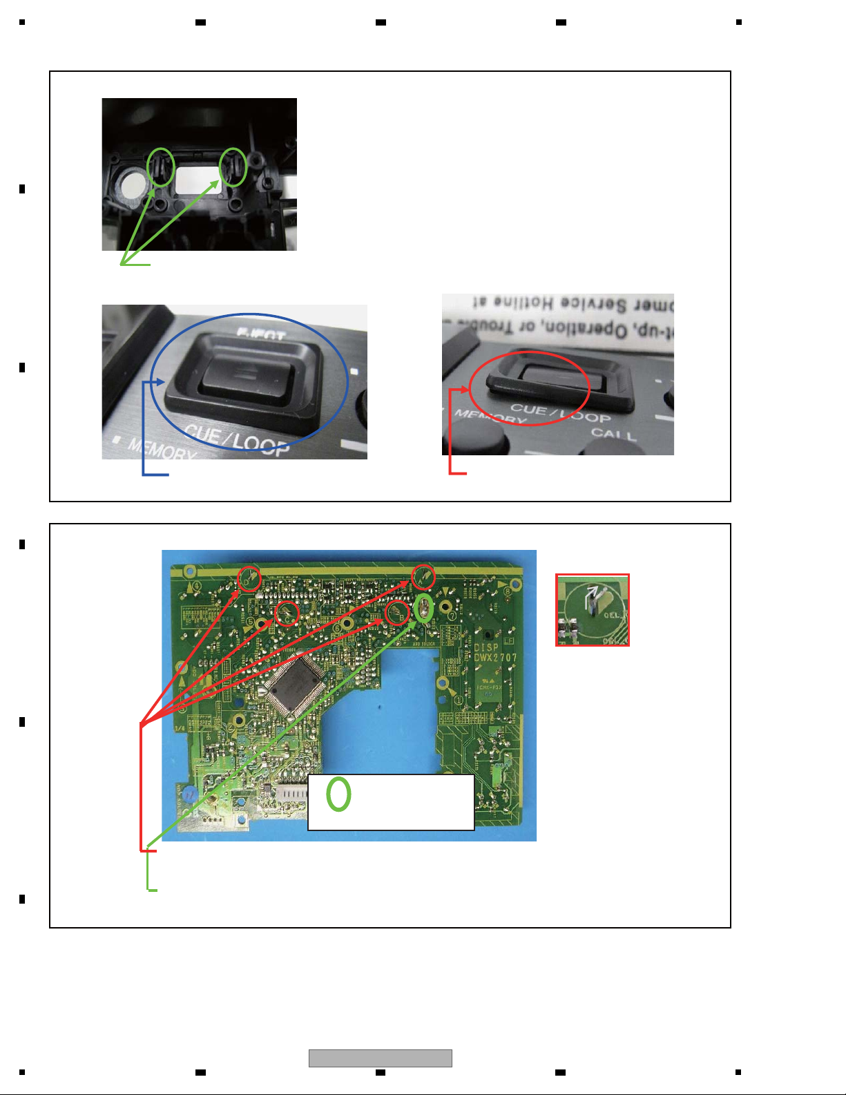
1
Points to be checked about the EJECT guard
Point to be checked when reassembling:
Check that the hooks are properly engaged.
OK: No lifting when visually checked
Bend the hooks according to the printed indications pointed out here, in the order of A, B, C, then D.
When attaching the OELB unit to the DISP Assy, perform additional soldering.
Point soldering
The holes need not be filled.
NG: Lifted
A
B
2 3 4
C
D
E
F
16
1
2 3 4
MEP-7000
Page 17
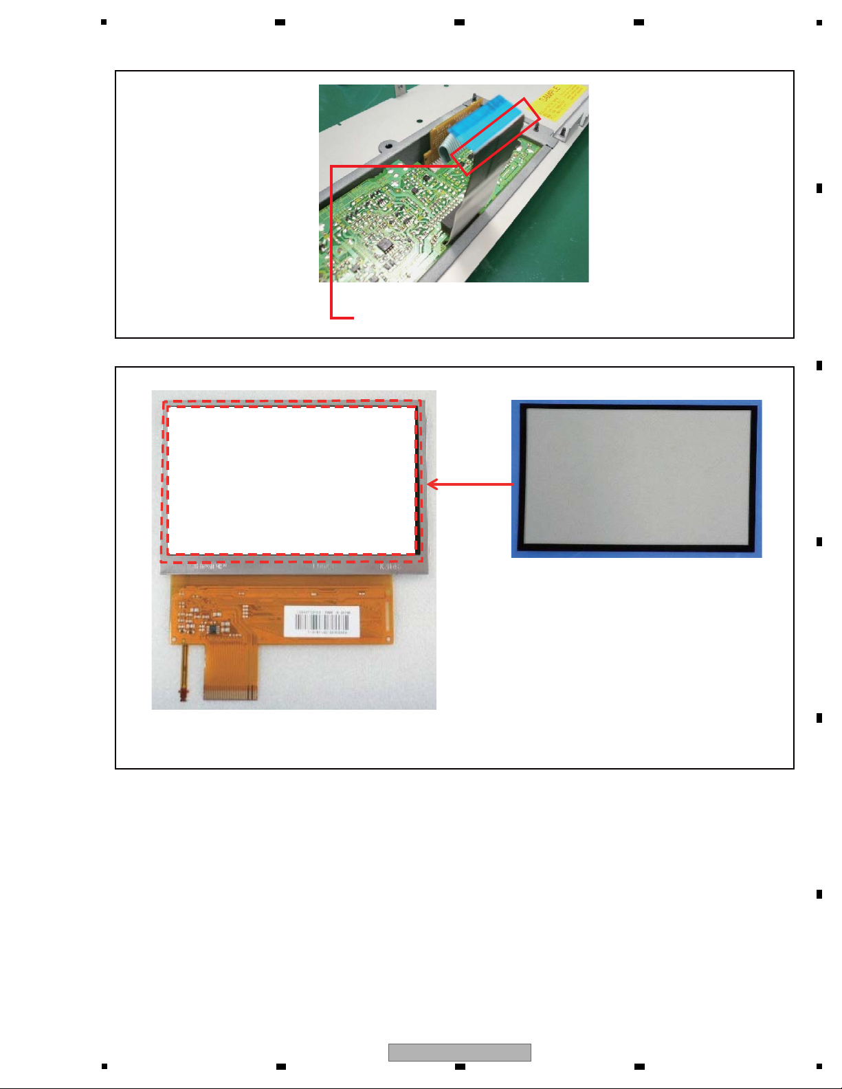
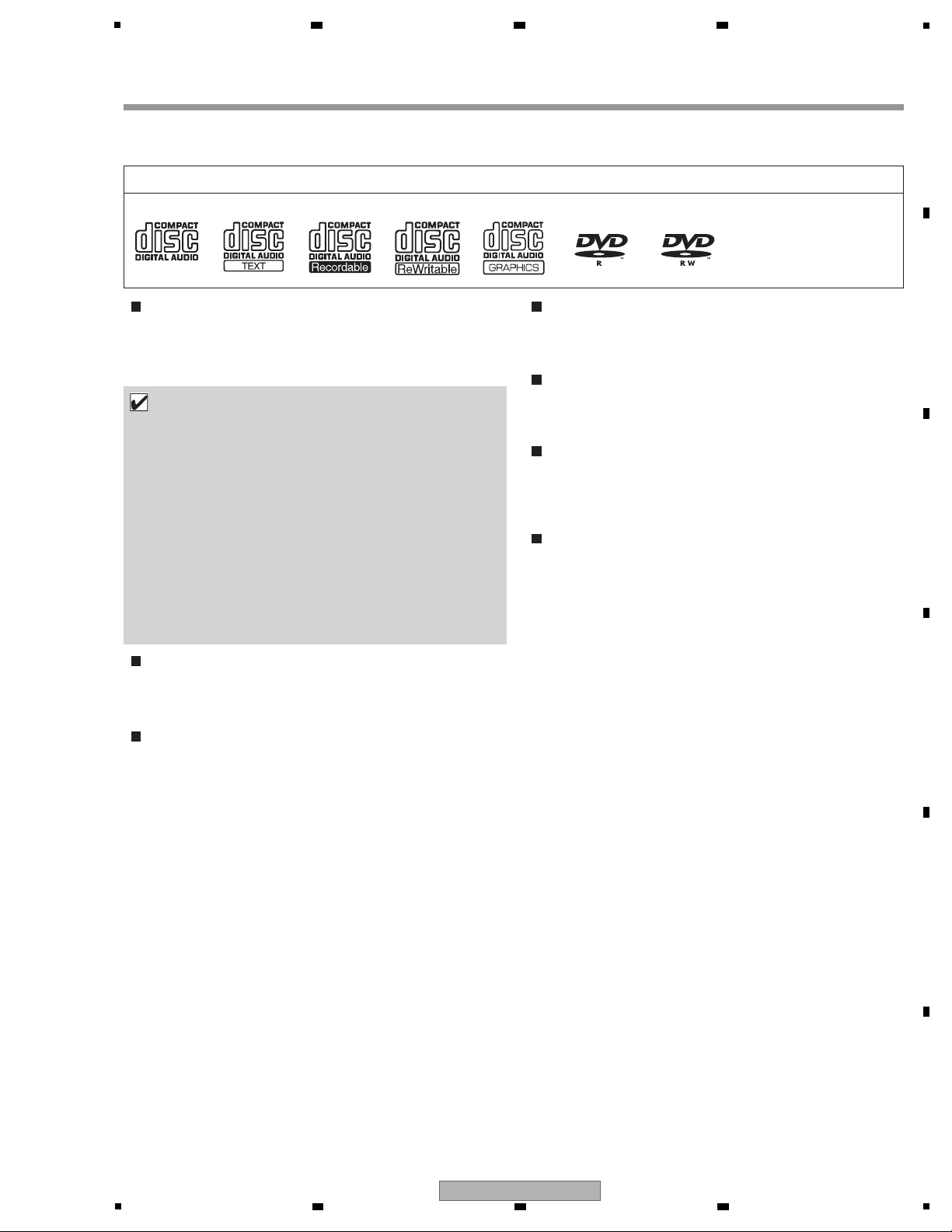
5
The FFC cables from the NJACK Assy to the NMAIN Assy
must be folded at a right angle at the base of the reinforcing plate.
Place on the LCD module so that it will not be positioned
outside the module.
Paste.
6 7 8
A
B
C
D
E
F
MEP-7000
5
6 7 8
17
Page 18

1
C
AUT
I
ON
Audio Cables
(XDE3045) L=1.5m
Forced Eject Pin
(DEX1008)
Caution Tag AP
(DRW1897)
Power Cord
(ADG7021 : KUCXJ)
(ADG7097 : TLFXJ)
(ADG7079 : WAXJ5)
(ADG1154 : WYXJ5,TLFXJ)
Control Cord
(XDE3063) L=1 m
Accessories
• Operating Instructions
(KUCXJ: DRB1455)
(WYXJ5: DRB1456, DRB1464)
(TLFXJ: DRB1457)
(WAXJ5: DRB1471)
DJS CD-ROM Assy
(DXX2585)
DJS installation key sticker
(DRM1300)
except WAXJ5
• Warranty Card
Dedicated remote control cable
(DDE1115)
USB Cable
(DDE1128)
USB auxiliary power cable
(DDE1129)
2. SPECIFICATIONS
2.1 ACCESSORIES
A
2 3 4
B
C
D
E
F
18
1
2 3 4
MEP-7000
Page 19

5
• KUCXJ type
• WYXJ5 type
1 General
Model . . . . . . . . . . . . . . . . . . . . . . . . . . . . . . . . . . . . . . . . . MEP-7000
Name . . . . . . . . . . . . . . . . . . . . . . . . . . . Multi entertainment player
Normal style
Power voltage . . . . . . . . . . . . . . . . . . . . . . . . . . . AC 120 V, 60 Hz
Power consumption . . . . . . . . . . . . . . . . . . . . . . . . . . . . . . . 32 W
Manipulator style
Power voltage . . . . . . . . . . . . . . . . . . . . DC 5 V (USB bus-power)
Current consumption . . . . . . . . . . . . . . . . . . . . . . . . . . . . 600 mA
Power consumption . . . . . . . . . . . . . . . . . . . . . . . . . . . . . . . . 3 W
Operating temperature . . . . . . +5 °C to +35 °C (+41 °F to +95 °F)
Operating humidity . . . . . 5 % to 85 % RH (without condensation)
Mass (Weight)
Control unit . . . . . . . . . . . . . . . . . . . . . . . . . . . . . . 1.7 kg (3.75 lb.)
Drive unit . . . . . . . . . . . . . . . . . . . . . . . . . . . . . . . 6.1 kg (13.45 lb.)
Maximum external dimensions
Control unit . . . . . 482.6 mm (W) x 133.0 mm (H) x 83.5 mm (D)
19.0 in (W) x 5.24 in (H) 3.29 in (D)
Drive unit . . . . . . . 482.6 mm (W) x 90.5 mm (H) x 324.6 mm (D)
19.0 in (W) x 3.56 in (H) 12.78 in (D)
2 USB Upstream Section
Connector. . . . . . . . . . . . . . . . . . . USB B-type port (PC connector)
USB Downstream Section
Connector. . . . . . . . . . . . . . . USB A-type ports (USB1/USB2 ports)
Power supply . . . . . . . . . . . . . . . . . . . . 5 V/500 mA or less (at port)
3 Analog Audio Output Section
Output connector . . . . . . . . . . . . . . . . . RCA jacks (controller A/B)
Output level . . . . . . . . . . . . . . . . . . . . . . . . . . . . . . . 2.0 Vrms (1 kHz)
Frequency response . . . . . . . . . . . . . . . . . . . . . . . . . 4 Hz to 20 kHz
S/N ratio . . . . . . . . . . . . . . . . . . . . . . . . . . . . 115 dB or more (JEITA)
Distortion . . . . . . . . . . . . . . . . . . . . . . . . . . . 0.006 % or less (JEITA)
* The above specifications refer to values for music CD (CDDA).
4 Digital Audio Output Section
Output connector . . . . . . . . . . . . . . . . . RCA jacks (controller A/B)
Output type. . . . . . . . . . . . . . . . . . . . . . . . . . Coaxial digital (S/PDIF)
Output level . . . . . . . . . . . . . . . . . . . . . . . . . . . . . . . . 0.5 Vp-p (75
Ω)
Output format . . . . . . . . . . . . . . . . . . . . . . . . . . . . . . 44.1 kHz/16 bit
5 Video Output Section
Output connector . . . . . . . . . . . . . . . . . . . . . . . . . . . . . . . . RCA jack
Composite output level . . . . . . . . . . . . . . . . . . . . . . . . .1 Vp-p (75
Ω)
6 Center Display Section
Type. . . . . . . . . . . . . . . . . . . . . . . . . . . TFT LCD active matrix display
Size . . . . . . . . . . . . . . . . . . . . . . . . . . . . . . . . . . . . . . . . . . 4.3” (WIDE)
Supported languages
. . . . . . 9 languages including English, Japanese, and Chinese
7 Controller Display A/B Section
Type. . . . . . . . . . . . . . . . . . . . . . . . . OEL (Organic EL) Full segment
8 Other Connectors
Control unit
Remote control connector . . . . . . . . . . . . . . . . . Mini-DIN 10-pin
5 V connector. . . . . . . . . . . . . . . . . . . . . . . . . . . . . . . . . . . DC jack
Drive unit
Remote control connector . . . . . . . . . . . . . . . . . Mini-DIN 10-pin
Control jack . . . . . . . . . . . . . . . . . . . . Mini-jacks (controller A/B)
Specifications and appearance are subject to change without
notice.
1 General
Model . . . . . . . . . . . . . . . . . . . . . . . . . . . . . . . . . . . . . . . . . MEP-7000
Name . . . . . . . . . . . . . . . . . . . . . . . . . . . Multi entertainment player
Normal style
Power voltage. . . . . . . . . . . . . . . AC 220 V to 240 V, 50 Hz/60 Hz
Power consumption . . . . . . . . . . . . . . . . . . . . . . . . . . . . . . . 33 W
Manipulator style
Power voltage. . . . . . . . . . . . . . . . . . . . . DC 5 V (USB bus-power)
Current consumption . . . . . . . . . . . . . . . . . . . . . . . . . . . . 600 mA
Power consumption . . . . . . . . . . . . . . . . . . . . . . . . . . . . . . . . 3 W
Operating temperature . . . . . . . . . . . . . . . . . . . . . . +5 °C to +35 °C
Operating humidity . . . . . 5 % to 85 % RH (without condensation)
Mass (Weight)
Control unit . . . . . . . . . . . . . . . . . . . . . . . . . . . . . . . . . . . . . 1.7 kg
Drive unit . . . . . . . . . . . . . . . . . . . . . . . . . . . . . . . . . . . . . . . 6.1 kg
Maximum external dimensions
Control unit . . . . . 482.6 mm (W) x 133.0 mm (H) x 83.5 mm (D)
Drive unit . . . . . . . 482.6 mm (W) x 90.5 mm (H) x 324.6 mm (D)
2 USB Upstream Section
Connector. . . . . . . . . . . . . . . . . . . USB B-type port (PC connector)
USB Downstream Section
Connector. . . . . . . . . . . . . . . USB A-type ports (USB1/USB2 ports)
Power supply . . . . . . . . . . . . . . . . . . . . 5 V/500 mA or less (at port)
3 Analog Audio Output Section
Output connector . . . . . . . . . . . . . . . . . RCA jacks (controller A/B)
Output level . . . . . . . . . . . . . . . . . . . . . . . . . . . . . . 2.0 Vrms (1 kHz)
Frequency response . . . . . . . . . . . . . . . . . . . . . . . . . 4 Hz to 20 kHz
S/N ratio . . . . . . . . . . . . . . . . . . . . . . . . . . . . 115 dB or more (JEITA)
Distortion . . . . . . . . . . . . . . . . . . . . . . . . . . . 0.006 % or less (JEITA)
* The above specifications refer to values for music CD (CD-
DA).
4 Digital Audio Output Section
Output connector . . . . . . . . . . . . . . . . . RCA jacks (controller A/B)
Output type. . . . . . . . . . . . . . . . . . . . . . . . . . Coaxial digital (S/PDIF)
Output level . . . . . . . . . . . . . . . . . . . . . . . . . . . . . . . . 0.5 Vp-p (75 Ω)
Output format . . . . . . . . . . . . . . . . . . . . . . . . . . . . . . 44.1 kHz/16 bit
5 Video Output Section
Output connector . . . . . . . . . . . . . . . . . . . . . . . . . . . . . . . .RCA jack
Composite output level . . . . . . . . . . . . . . . . . . . . . . . . .1 Vp-p (75 Ω)
6 Center Display Section
Type. . . . . . . . . . . . . . . . . . . . . . . . . . .TFT LCD active matrix display
Size . . . . . . . . . . . . . . . . . . . . . . . . . . . . . . . . . . . . . . . . . 4.3” (WIDE)
Supported languages
. . . . . . . 9 languages including English, Japanese, and Chinese
7 Controller Display A/B Section
Type. . . . . . . . . . . . . . . . . . . . . . . . . OEL (Organic EL) Full segment
8 Other Connectors
Control unit
Remote control connector . . . . . . . . . . . . . . . . . Mini-DIN 10-pin
5 V connector. . . . . . . . . . . . . . . . . . . . . . . . . . . . . . . . . . DC jack
Drive unit
Remote control connector . . . . . . . . . . . . . . . . . Mini-DIN 10-pin
Control jack . . . . . . . . . . . . . . . . . . . . Mini-jacks (controller A/B)
Specifications and appearance are subject to change without
notice.
2.2 SPECIFICATIONS
6 7 8
A
B
5
6 7 8
MEP-7000
C
D
E
F
19
Page 20

1
• TLFXJ type • WAXJ5 type
1 General
Model . . . . . . . . . . . . . . . . . . . . . . . . . . . . . . . . . . . . . . . . MEP-7000
Name . . . . . . . . . . . . . . . . . . . . . . . . . . . Multi entertainment player
Normal style
Power voltage. . . . . . . . . . . . . . . AC 110 V to 240 V, 50 Hz/60 Hz
Power consumption . . . . . . . . . . . . . . . . . . . . . . . . . . . . . . . 33 W
Manipulator style
Power voltage. . . . . . . . . . . . . . . . . . . . . DC 5 V (USB bus-power)
Current consumption . . . . . . . . . . . . . . . . . . . . . . . . . . . . 600 mA
Power consumption . . . . . . . . . . . . . . . . . . . . . . . . . . . . . . . . 3 W
Operating temperature . . . . . . . . . . . . . . . . . . . . . . +5 °C to +35 °C
Operating humidity . . . . . 5 % to 85 % RH (without condensation)
Mass (Weight)
Control unit . . . . . . . . . . . . . . . . . . . . . . . . . . . . . . . . . . . . . 1.7 kg
Drive unit . . . . . . . . . . . . . . . . . . . . . . . . . . . . . . . . . . . . . . . 6.1 kg
Maximum external dimensions
Control unit . . . . . 482.6 mm (W) x 133.0 mm (H) x 83.5 mm (D)
Drive unit . . . . . . . 482.6 mm (W) x 90.5 mm (H) x 324.6 mm (D)
2 USB Upstream Section
Connector. . . . . . . . . . . . . . . . . . . USB B-type port (PC connector)
USB Downstream Section
Connector. . . . . . . . . . . . . . . USB A-type ports (USB1/USB2 ports)
Power supply . . . . . . . . . . . . . . . . . . . . 5 V/500 mA or less (at port)
3 Analog Audio Output Section
Output connector . . . . . . . . . . . . . . . . . RCA jacks (controller A/B)
Output level . . . . . . . . . . . . . . . . . . . . . . . . . . . . . . 2.0 Vrms (1 kHz)
Frequency response . . . . . . . . . . . . . . . . . . . . . . . . . 4 Hz to 20 kHz
S/N ratio . . . . . . . . . . . . . . . . . . . . . . . . . . . . 115 dB or more (JEITA)
Distortion . . . . . . . . . . . . . . . . . . . . . . . . . . . 0.006 % or less (JEITA)
* The above specifications refer to values for music CD (CD-
DA).
4 Digital Audio Output Section
Output connector . . . . . . . . . . . . . . . . . RCA jacks (controller A/B)
Output type. . . . . . . . . . . . . . . . . . . . . . . . . . Coaxial digital (S/PDIF)
Output level . . . . . . . . . . . . . . . . . . . . . . . . . . . . . . . . 0.5 Vp-p (75 Ω)
Output format . . . . . . . . . . . . . . . . . . . . . . . . . . . . . . 44.1 kHz/16 bit
5 Video Output Section
Output connector . . . . . . . . . . . . . . . . . . . . . . . . . . . . . . . .RCA jack
Composite output level . . . . . . . . . . . . . . . . . . . . . . . . .1 Vp-p (75 Ω)
6 Center Display Section
Type. . . . . . . . . . . . . . . . . . . . . . . . . . .TFT LCD active matrix display
Size . . . . . . . . . . . . . . . . . . . . . . . . . . . . . . . . . . . . . . . . . 4.3” (WIDE)
Supported languages
. . . . . . . 9 languages including English, Japanese, and Chinese
7 Controller Display A/B Section
Type. . . . . . . . . . . . . . . . . . . . . . . . . OEL (Organic EL) Full segment
8 Other Connectors
Control unit
Remote control connector . . . . . . . . . . . . . . . . . Mini-DIN 10-pin
5 V connector. . . . . . . . . . . . . . . . . . . . . . . . . . . . . . . . . . DC jack
Drive unit
Remote control connector . . . . . . . . . . . . . . . . . Mini-DIN 10-pin
Control jack . . . . . . . . . . . . . . . . . . . . Mini-jacks (controller A/B)
Specifications and appearance are subject to change without
notice.
1 General
Model . . . . . . . . . . . . . . . . . . . . . . . . . . . . . . . . . . . . . . . . MEP-7000
Name . . . . . . . . . . . . . . . . . . . . . . . . . . . Multi entertainment player
Normal style
Power voltage. . . . . . . . . . . . . . . AC 220 V to 240 V, 50 Hz/60 Hz
Power consumption . . . . . . . . . . . . . . . . . . . . . . . . . . . . . . . 33 W
Manipulator style
Power voltage. . . . . . . . . . . . . . . . . . . . . DC 5 V (USB bus-power)
Current consumption . . . . . . . . . . . . . . . . . . . . . . . . . . . . 600 mA
Power consumption . . . . . . . . . . . . . . . . . . . . . . . . . . . . . . . . 3 W
Operating temperature . . . . . . . . . . . . . . . . . . . . . . +5 °C to +35 °C
Operating humidity . . . . . 5 % to 85 % RH (without condensation)
Mass (Weight)
Control unit . . . . . . . . . . . . . . . . . . . . . . . . . . . . . . . . . . . . . 1.7 kg
Drive unit . . . . . . . . . . . . . . . . . . . . . . . . . . . . . . . . . . . . . . . 6.1 kg
Maximum external dimensions
Control unit . . . . . 482.6 mm (W) x 133.0 mm (H) x 83.5 mm (D)
Drive unit . . . . . . . 482.6 mm (W) x 90.5 mm (H) x 324.6 mm (D)
2 USB Upstream Section
Connector. . . . . . . . . . . . . . . . . . . USB B-type port (PC connector)
USB Downstream Section
Connector. . . . . . . . . . . . . . . USB A-type ports (USB1/USB2 ports)
Power supply . . . . . . . . . . . . . . . . . . . . 5 V/500 mA or less (at port)
3 Analog Audio Output Section
Output connector . . . . . . . . . . . . . . . . . RCA jacks (controller A/B)
Frequency response . . . . . . . . . . . . . . . . . 20 Hz to 20 kHz +1/-3 dB
S/N ratio . . . . . . . . . . . . . . . . . . . . . . . . . . . . 115 dB or more (JEITA)
Distortion . . . . . . . . . . . . . . . . . . . . . . . . . . . 0.006 % or less (JEITA)
* The above specifications refer to values for music CD (CD-
DA).
4 Digital Audio Output Section
Output connector . . . . . . . . . . . . . . . . . RCA jacks (controller A/B)
Output type. . . . . . . . . . . . . . . . . . . . . . . . . . Coaxial digital (S/PDIF)
Output level . . . . . . . . . . . . . . . . . . . . . . . . . . . 0.5 ± 0.1 Vp-p (75 Ω)
Output format . . . . . . . . . . . . . . . . . . . . . . . . . . . . . . 44.1 kHz/16 bit
5 Video Output Section
Output connector . . . . . . . . . . . . . . . . . . . . . . . . . . . . . . . .RCA jack
Composite output level . . . . . . . . . . . . . . . . . . . . . 1 ± 0.1 Vp-p (75 Ω)
6 Center Display Section
Type. . . . . . . . . . . . . . . . . . . . . . . . . . .TFT LCD active matrix display
Size . . . . . . . . . . . . . . . . . . . . . . . . . . . . . . . . . . . . . . . . . 4.3” (WIDE)
Supported languages
. . . . . . . 9 languages including English, Japanese, and Chinese
7 Controller Display A/B Section
Type. . . . . . . . . . . . . . . . . . . . . . . . . OEL (Organic EL) Full segment
8 Other Connectors
Control unit
Remote control connector . . . . . . . . . . . . . . . . . Mini-DIN 10-pin
5 V connector. . . . . . . . . . . . . . . . . . . . . . . . . . . . . . . . . . DC jack
Drive unit
Remote control connector . . . . . . . . . . . . . . . . . Mini-DIN 10-pin
Control jack . . . . . . . . . . . . . . . . . . . . Mini-jacks (controller A/B)
Specifications and appearance are subject to change without
notice.
A
B
2 3 4
C
D
E
F
20
1
2 3 4
MEP-7000
Page 21
5
TYPES OF DISCS PLAYABLE ON THIS UNIT
• Playable discs will display one of the following logo marks on the disc label, packaging, or jacket:
About disc playback
This unit can play CD-R/CD-RW discs recorded in music CD (CDDA) or CD graphics (CD-G) format, and CD-R/-RW, DVD-R/-RW,
DVD+R/+RW, and DVD±R dual layer discs recorded in MP3/AAC
file format.
The following discs cannot be played on this unit
CDs: DTS-CDs, photo-CDs, video-CDs, and unfinalized CDs
DVDs: DVD video, DVD audio, DVD-RAM, unfinalized DVDs, MPEG
moving picture files
Backup your discs!
Due to structural characteristics of CD-R/-RW, DVD-R/-RW,
DVD+R/+RW, and DVD±R dual layer media, if such discs are left
for extended periods in the pause (or cue standby) mode, they
become unplayable or difficult to play at that point on the disc. The
same symptom may occur if the loop function is used to repeat the
same section of a disc for an extremely large number of times.
When using discs holding important files or tracks, always make
backups first.
About copy-control CDs
This unit is designed to comply with music CD standards. We
cannot guarantee operation or performance when using discs that
do not comply with these standards.
[DualDisc] playback
This unit is designed to comply with music CD standards. We
cannot guarantee operation or performance when using discs that
do not comply with these standards.
About 8 cm single CDs
8 cm single CDs cannot be played on this unit. Also, do not
attempt to attach an 8 cm adapter to a disc and play it in this unit,
since the adapter may become detached during playback, causing
damage to the disc or player.
About CD-TEXT on music CDs
This unit supports CD-TEXT, and displays track titles, album titles,
and artist names recorded in CD-TEXT. Supported character codes
include ASCII, ISO-8859, MS-JIS, and Mandarin Chinese. When
multiple text data are recorded, the first text data is displayed.
Playable disc types and logos
CD CD-TEXT CD-R CD-RW CD-G DVD-R DVD-RW
The DVD mark is a
trademark of DVD Format/
Licensing Logo Corporation.
NOTE
• CD-R/-RW, DVD-R/-RW, DVD+R/+RW, and DVD±R dual
layer discs recorded on a standalone recorder or computer
may not play properly on this unit for a variety of reasons,
including individual characte ristics of the disc, scratches
or soiling of the disc, or dirt or condensation on the player’s
laser lens.
• Discs recorded on a computer’s disc drive may not play
properly due to variations in the recording software settings
or computer environment. Besure to record discs in the
proper format (for details, consult the distributor of the
recording software application).
• For detailed information regarding the handling and use of
your disc media, consult the precautions and instructions
furnished with the discs.
6 7 8
2.3 REGARDING PLAYABLE DISCE AND FILES
A
B
C
D
E
F
MEP-7000
5
6 7 8
21
Page 22
1
ABOUT MP3/AAC DISC PLAYBACK
This unit can play compressed music files (MP3/AAC) recorded on CD-R/-RW, DVD-R/-RW, DVD+R/+RW,
and DVD±R dual layer media.
• Startup time will increases as the number of folders and files increases.
ABOUT PLAYBACK FROM USB STORAGE DEVICE
By connecting a USB storage device to this unit, MP3/AAC/WAV/AIFF files recorded on the device can be played on this unit.
To disconnect a USB storage device
Hold the STOP button depressed for two seconds or more. Wait to remove the device until after the red indicator changes from flashing
to off.
Folder levels Maximum 8 levels; if more than 8 levels exist,files in the 9th and further levels cannot be played.
Maximum folders 2 000 per disc. If more than 2 000 folders exist, those beyond 2 000 cannot be displayed.
Maximum files 3 000 per disc. If more than 3 000 files exist, those beyond 3 000 cannot be displayed.
Recording format Supports discs recorded using the ISO9660 file system.
When recording is performed using the UDF file system, the disc cannot be played if the ISO9660 file
system is not recorded jointly. For details, consult the author of the application.
Folder levels Maximum 8 levels; if more than 8 levels exist, files in the 9th and further levels cannot be played.
Maximum folders No specific folder limit is made for a device, but folders exceeding 10 000 in a folder cannot be displayed.
Maximum files No specific file limit is made for a device, but a files exceeding 10 000 in a folder cannot be displayed.
Supported file systems FAT, FAT32, HFS+
MEMO
• USB storage devices supported by this unit are of the class of USB mass storagedevices including external hard discs,
portable flash memory devices, and digital audio player.
However, optical disc devices such as external DVD/CD drives cannot be used.
• When connecting a USB storage device containing a large number of folders and files, some time may be required to read
in the device contents.
• When a connected USB storage device contains multiple partitions, only the initial partition can be used.
CAUTION
Depending on the device used, proper playback may not be possible with all USB storage devices.
Pioneer assumes no responsibility for any loss of data resulting from connecting any given USB device to this
unit.
• Proper operation may not be possible when a USB storage device is connected through a USB hub.
• Even if a USB hub is used to connect multiple USB storage devices, the second and later devices cannot be used.
• Operation cannot be guaranteed when using a USB storage device with installed flash card reader.
• When connecting a USB storage device utilizing two USB cables, connect both cables to this unit’s USB ports.
• If an electrical current stronger than the allowable current is applied to the unit’s USB1 port or USB2 port, the unit may stop
supplying power to the USB storage device, thus terminating transmission. In this case, a message will be displayed in the
center display of the unit, and the stop indicators for USB1 and USB2 will flash red simultaneously. To restore normal
operation, disconnect all USB storage devices connected to the unit, then hold either of the USB STOP buttons depressed
for two seconds or more. Avoid connecting the USB storage device from which the excess current was detected and other
USB storage devices connected through a bus-powered USB hub. If normal operation is not restored through this method,
turn the power of this unit off, and then turn it back on.
CAUTION
When disconnecting a USB storage device, always be sure to perform the STOP operation first. If the STOP
operation is not completed before disconnection, cue/loop memory and playlist update may not occur properly,
resulting in the loss of data. Also, the USB storage device may becomes unreadable, or other substantial damage
may occur. Always disconnect the USB storage device before turning off the power to this unit.
A
2 3 4
B
C
D
E
F
22
MEP-7000
1
2 3 4
Page 23
5
ABOUT MP3 FILES
MP3 files may be found in two types, those with Constant Bit Rate (CBR), and those with Variable Bit Rate (VBR). This player supports
playback and DJ play of both CBR and VBR type files, but VBR files may exhibit slower performance when using search and super fast
search functions, compared to CBR files. When playback performance is preferred, record your files using CBR.
This unit supports MP3 files subject to the following formats:
*1 In order to display characters written in a local code other than Unicode, the UTILITY function must be used to set the language.
*2 Files with original image size larger than 800 x 800 pixels cannot be displayed.
ABOUT AAC FILES
AAC is an abbreviation for Advance Audio Coding, a basic format relating the audio compression technology used for MPEG-2 and
MPEG-4.
AAC data differs in file format and extension depending on the application used to create the data file.
The MEP-7000 is capable of playing iTunes -encoded AAC files with extension .m4a, as well as .aac and .mp4 files. However, copy-
®
protected files purchased at places like iTunes Music Store cannot be played. Further, some files may not be playable, depending on
the version of iTunes in which they were encoded.
Apple and iTunes are trademarks of Apple Inc., registered in the U.S. and other countries.
This unit supports AAC files subject to the following formats:
*1 In order to display characters written in a local code other than Unicode, the UTILITY function must be used to set the language.
*2 Files with original image size larger than 800 x 800 pixels cannot be displayed.
Supported formats MPEG-1 Supports Audio Layer-3 sampling frequencies 32 kHz, 44.1 kHz, 48 kHz, with bit
rates of 32 Kbps to 320 Kbps.
MPEG-2 Supports Audio Layer-3 sampling frequencies 16 kHz, 22.05 kHz, 24 kHz, with bit
rates of 16 Kbps to 160 Kbps.
Supports ID3 tag Ver 1.0/1.1/2.2/2.3/2.4.Track data
Displays title, album name, artist’s name. *1
JPEG images embedded in ID3 tag are displayed as jacket photographs. *2
.mp3File extensions
Supported formats MPEG-4 AAC LE Sampling frequency 16 kHz, 22.05 kHz, 24 kHz, 32 kHz, 44.1 kHz, 48 kHz,
with bit rates of 8 Kbps to 320 Kbps.
Track data AAC files
Supports ID3 tag Ver 1.0/1.1/2.2/2.3/2.4.
Displays title, album name, artist’s name. *1
JPEG images embedded in ID3 tag are displayed as jacket photographs. *2
Non-AAC files
Support metatags (embedded tags).
Displays title, album name, artist’s name. *1
JPEG images embedded in tag are displayed as jacket photographs. *2
.m4a, .aac, .mp4File extensions
6 7 8
A
B
C
D
MEP-7000
5
6 7 8
E
F
23
Page 24
1
ABOUT WAV FILES
This unit supports WAV files subject to the following formats:
*1 In order to display characters written in a local code other than Unicode, the UTILITY function must be used to set the language.
ABOUT AIFF FILES
This unit supports AIFF files subject to the following formats:
*1 In order to display characters written in a local code other than Unicode, the UTILITY function must be used to set the language.
Supported formats Supports 16-bit non-compressed PCM, with sampling frequency of 44.1 kHz.
Track data
Supports LST chunk.
Displays title, album name, artist’s name. *1
File extension .wav
MEMO
• WAV files recorded in disc media are not supported.
Supported formats Supports 16-bit non-compressed PCM, with sampling frequency of 44.1 kHz.
Displays title, album name, artist’s name. *1
File extension .aif .aiff
MEMO
• AIFF files recorded in disc media are not supported.
A
2 3 4
B
C
D
E
F
24
1
2 3 4
MEP-7000
Page 25
2.4 PANEL FACILITIES
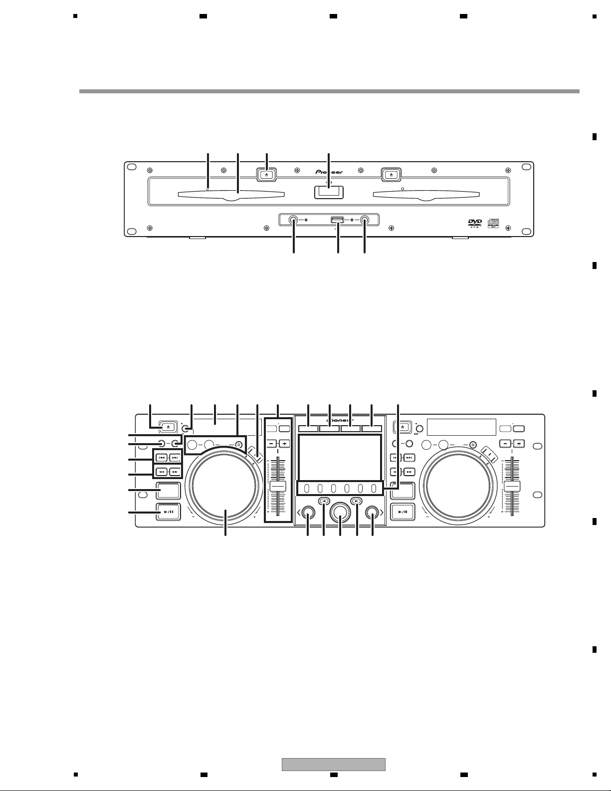
FRONT PANEL
Drive Unit
1 Forced eject hole
2 Disc loading slot
3EJECT () button
To eject a disc from the disc loading slot, press this button
during the cue standby or pause mode, or when no tracks are
being loaded from the disc.
4 POWER switch and indicator
Turns unit power ON/OFF.
5 USB1 STOP button and indicator
Press when removing a USB memory device from USB1 port.
6 USB2 STOP button and indicator
Press when removing a USB memory device from USB2 port.
7 USB2 input port (type A)
Use to connect a USB memory device.
Control Unit
1 EJECT ( ) button
To eject a disc from the disc loading slot, press this button
during the cue standby or pause mode, or when no tracks are
being loaded from the disc.
2 LOOP operation button
3 TEMPO control section
TEMPO control range button (±6/10/16/WIDE):
Each time the button is pressed, the variable range of the
TEMPO adjust slider changes.
MASTER TEMPO button and indicator (MT):
Each time the button is pressed, the master tempo function
alternates ON/OFF.
TEMPO adjust slider:
From the center detent position, pull the slider towards you (+)
to increase the tempo, and push the slider away from you (–)
to slow down the tempo.
PITCH BEND +/– buttons:
When pressed during play, the pitch bend function is enabled.
Pressing the “+” button accelerates the pitch bend speed, and
pressing the “–” button decelerates the pitch bend speed.
The speed of the pitch change can be modified by holding the
button depressed while rotating the jog dial.
EJECT
POWER
STOP STOPREAR
DISC 1
USB 1 USB 2
DISC 2
EJECT
MEP-7000
MULTI ENTERTAINMENT PLAYER
1 2 3 4
56
7
TRACK SEARCH
CUE/LOOP
EJECT
TIME
A.CUE
IN/CUE
HOT LOOP
LOOP
RELOOP/EXIT
PITCH BEND
BROWSE MIX EFFECT UTILITY
MT
0
MASTER
TEMPO
TEMPO
6/10/16WIDE
OUT/ADJUST
FWD TEMPOREV
MEMORY CALL
SEARCH
QUE
J
O
G
B
R
E
A
K
S
C
R
A
T
C
H
TRACK SEARCH
CUE/LOOP
EJECT
TIME
A.CUE
IN/CUE
HOT LOOP
LOOP
RELOOP/EXIT
PITCH BEND
MT
0
MASTER
TEMPO
TEMPO
6/10/16WIDE
OUT/ADJUST
FWD TEMPOREV
MEMORY CALL
SEARCH
QUE
J
O
G
B
R
E
A
K
S
C
R
A
T
C
H
A
LOAD
B
MEP-7000
LOAD
MULTI ENTERTAINMENT PLAYER
1
15
4 22 2 3 10 11 12 13
18
18 14 20
21
1923
179
16
8
7
5
6
5
6 7 8
A
B
5
6 7 8
MEP-7000
C
D
E
F
25
Page 26

1
4 Time mode/auto cue button (TIME/A.CUE)
TIME:
Each time the button is pressed, the display’s time display
alternates between the currenttrack’s elapsed playing time,
and the remaining time (REMAIN).
A.CUE:
5 TRACK SEARCH ( , ) buttons
6 SEARCH ( , ) buttons
7 CUE button and indicator
Setting a cue point
Cue point sampler
Back-cue
Modifying a cue pint
8 Play/pause ( ) button and indicator
9 SCRATCH/JOG BREAK buttons and indicators
Use to select jog mode, including SCRATCH, JOG BREAK, or
OFF (neither indicator lighted).
10 BROWSE button
Use to select the BROWSE screen.
11 MIX button
Use to select the MIX screen.
12 EFFECT button
Use to select the EFFECT screen.
13 UTILITY button
Use to select the UTILITY screen.
14 Rotary selector dial
Rotate clockwise/counterclockwise for track selection and to
move cursor between setting items. Press to confirm
selection.
15 CUE/LOOP MEMORY button
Use to store cue points and loop points in memory.
Hold the button depressed to cancel a loop point.
16 CUE/LOOP CALL button
Use to call up cue and loop points stored in memory.
17 Function buttons (F1 to F6, from left)
Switching between the functions allocated to the six function
buttons can be performed by using the menu shown on the
center display.
On BROWSE screen:
“SELECT THE TRACK”
On MIX screen:
“MIX SCREEN”
On EFFECT screen
“[1] Scratch effect”
“[2] Jog break effect”
On UTILITY screen:
“USING MIDI FOR COMPUTER CONTROL”
“USING THE UTILITY”
18 LOAD A/B buttons
Sets the selected track in the controller A/B.
19 Select up ( ) button
Each time this button is pressed, the display returns to the next
higher menu level.
20 Select down ( ) button
Each time this button is pressed, the display advances to the
next lower menu level.
21 Center display
22 Display A/Display B
23 Jog dial (+FWD/–REV)
A
2 3 4
B
C
D
E
F
26
1
2 3 4
MEP-7000
Page 27
5
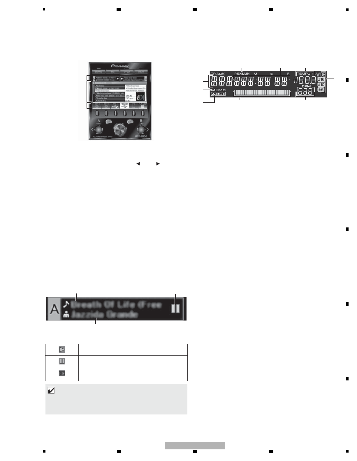
Center Display
1 Main menu display
The center display’s menus are changed by using the
BROWSE button, MIX button, EFFECT button, and UTILITY
button. The function buttons, select up ( )/down( ) buttons,
LOAD A/B buttons, and the rotary selector dial are used to
manipulate the contents of each menu.
BROWSE
screen
Use to select tracks and construct playlists.
MIX screen
Use to perform mixing operations, including auto mix using
playlists.
EFFECT
screen
Use to select scratch play and various effects used in jog break
play.
UTILITY
screen
Use to make unit settings.
2 Function tab
Displays items that can be changed using the six function
buttons. Items displayed differ depending on the contents
shown on the main menu display.
3 A/B track information display
Displays track information and current status for tracks
playing on controller A/B.
Play status
Display A/Display B
1 Track number display
Displays the number of the track currently playing.
2 TEMPO control range display (±6, ±10, ±16, WIDE)
Displays the selected variable range mode of the TEMPO
adjust slider.
3 TEMPO change ratio display
Displays the change in tempo produced by the operation of the
TEMPO adjust slider.
4 A.CUE indicator
Lights when the Auto Cue function is ON.
5Time display
Displays the current track’s elapsed time ([REMAIN] indicator
is off), or remaining time ([REMAIN] indicator is lighted), in
minutes [M], seconds [S], and frames [F].
6Playing address display
To provide a quick intuitive grasp of the relative progress of a
track’s playback (either elapsed time or remaining time), a bar
graph is used to represent the full length of the track.
• Elapsed time display: Starts with all segments off, then
gradually lights from left to right.
• Remaining time display: Starts with all segments on, then
gradually goes off from left to right.
• When 30 seconds of remaining playing time is reached, the
graph begins to flash slowly.
• When 15 seconds of remaining playing time is reached, the
graph begins to flash quickly.
7BPM display
Shows the currently playing track’s BPM (Beats Per Minute)
8 MEMO indicator
Lights when a cue or loop point has been stored in memory.
9 REMAIN indicator
Lights when the time display is set for remaining time.
Indicates track is currently playing.
Indicates track is currently paused.
Indicates track is currently in cue standby
condition ( “SETTING CUE POINTS”).
MEMO
• Track name and artist name can be displayed in Western
European languages, Russian, Chinese (simplified
Mandarin), and Japanese.
1
3
2
Play status Track name
Artist name
8
1
4
6
2
7
3
5
9
6 7 8
A
B
C
D
5
MEP-7000
6 7 8
E
F
27
Page 28
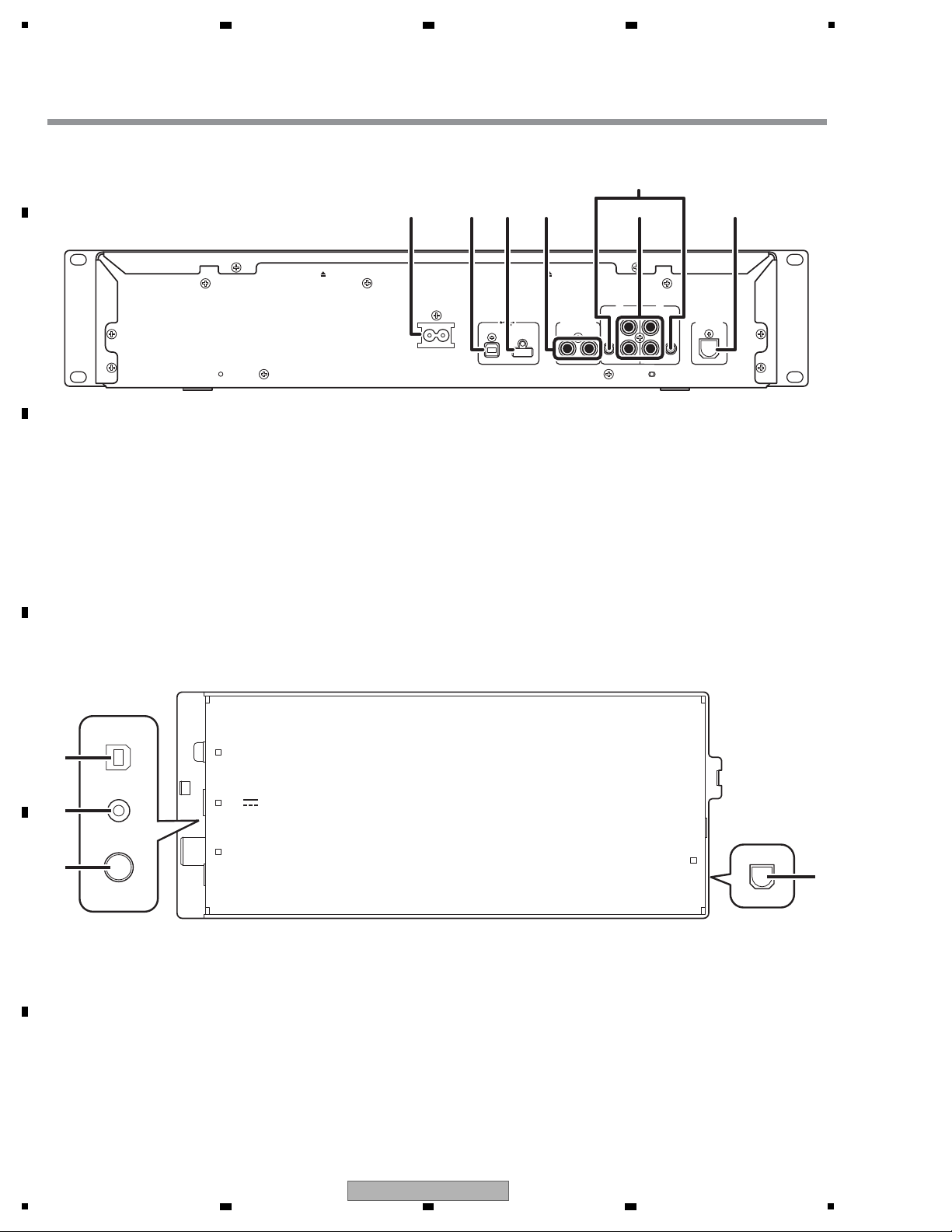
A
REAR PANEL
Drive Unit
1 AC inlet (AC IN)
Use the supplied power cord to connect this inlet to a
household AC outlet.
2 PC connector: USB port (type B)
Use the supplied USB cable to connect this port to a
computer.
3 USB1 port (type A)
Use to connect a USB storage device or USB keyboard.
4Digital output connectors (DIGITAL OUT A/B)
RCA-type coaxial digital output connector for connecting a DJ
mixer, AV amplifier, CD recorder or other component
supporting digital input.
The output supports all functions including DJ function, but
only audio data not including subcodes is output.
5 Control jacks (CONTROL A/B)
When the supplied control cord is used to connect this unit to
a Pioneer DJ mixer, the DJ mixer can be used to control this
unit so as to perform fader start play and back cue operations.
Also, by connecting this jack to another DJ player’s control
jack, automated relay play can be performed.*
* Relay play is disabled during DJ software track selection.
6 Audio output connectors (AUDIO OUT A/B)
RCA-type analog audio output connectors.
7 Remote control connector (REMOTE CONTROL)
Use the supplied dedicated remote control cable to connect to
the control unit.
Control Unit
1 PC connector: USB port (type B)
Use the accessory USB cable to connect this port to a
computer.
2 5 V connector
Use the accessory USB auxiliary power cable to connect to a
computer.
3 Video output connector (MONITOR OUT)
Use a video cable to connect to an external display.
4 Remote control connector (REMOTE CONTROL)
Use the supplied dedicated remote control cable to connect to
the drive unit.
AC IN
AB
DIGITAL OUT
REMOTE
CONTROL
AB
AUDIO OUTAUDIO OUT
L
R
CONTROL CONTROL
L
R
USB1PC
1 23 4 76
5
PC
MONITOR OUT
5V
REMOTE
CONTROL
1
2
3
4
1
2 3 4
B
C
D
E
F
28
MEP-7000
1
2 3 4
Page 29
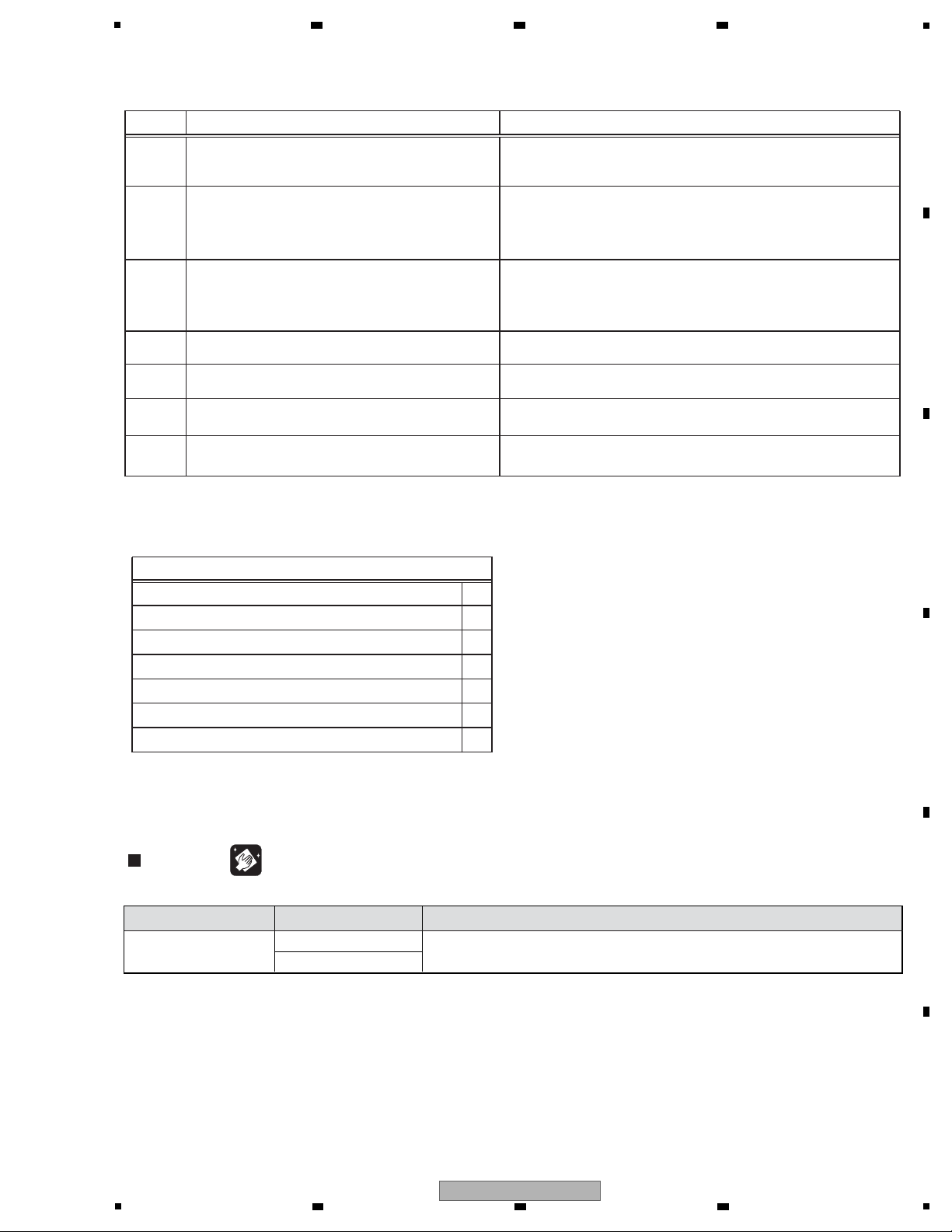
5
Cleaning
• Before shipping out the product, be sure to clean the following positions by using the prescribed cleaning tools:
Pickup leneses Cleaning liquid : GEM1004
Cleaning paper : GED-008
Refer to "7. DISASSEMBLY SECTION" ,"9.4 SLOT-IN MECHANISM SECTION" .
Position to be cleaned Cleaning tools Position to be cleaned Cleaning tools RemarkRemark Position to be cleaned Cleaning tools Remark
See the table below for the items to be checked regarding audio:
wol oot emuloV
Volume too high
Volume fluctuating
Sound interrupted
Check points
Procedures
No
Distortion
Noise
Item to be checked regarding audio
The sy mptoms in question must not be reproduced.
There must be no abnormality observed in audio signals or operations.
The result must meet the criteria (5.0e-4 or less).
In checking analog video output signals,
there must be no abnormality observed in video signals or operations.
Check video signals.
There must be no abnormality observed in audio signals or operations.
Check output signals while the JOG dial or TEMPO
slider is being operated.
Check that no scratch nor stain is added after the product is received
for repair.
Check the exterior.
1 Check the version of the firmware in Test mode.
Check that it is the latest version.
If it is not, update the firmware.
5
6
There must be no abnormality observed in audio signals or operations
of search.
2
Check that all the symptoms pointed out by the
customer have been addressed.
Measure the error rate of a CD/DVD.
Refer to “[5] DVD/CD Drive Diagnosis” of
“6.2 SERVICE MODE FOR THE DRIVE UNIT”.
3
4 Check the playback of a CD (Track search).
7
6 7 8
3. BASIC ITEMS FOR SERVICE
3.1 CHECK POINTS AFTER SERVICING
A
B
C
D
5
MEP-7000
6 7 8
E
F
29
Page 30
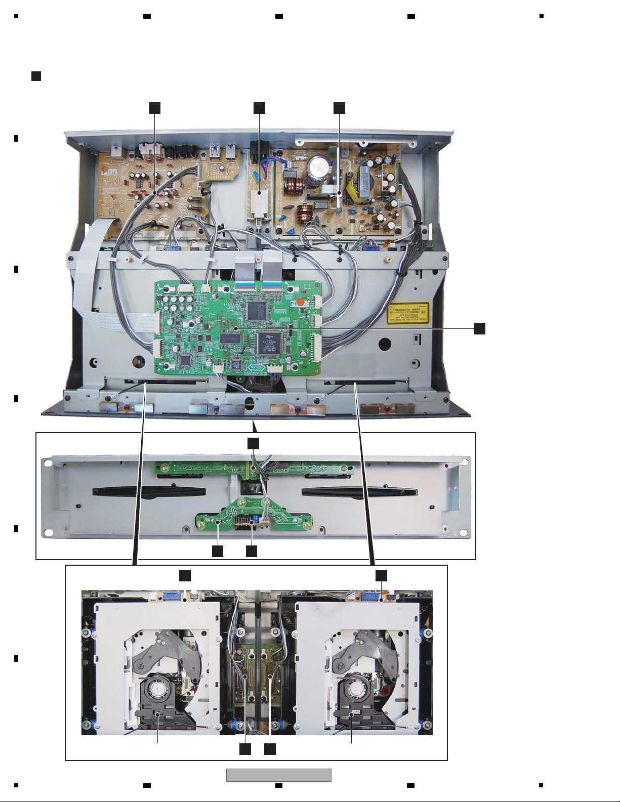
1
DRIVE UNIT
A
SMAIN ASSY
J
POWER SUPPLY UNIT
HE
SRV2 ASSY SLOT-IN MECHANISM ASSYSLOT-IN MECHANISM ASSY
G
USBB ASSY
C
FSWB ASSY
I
SLMB2 ASSY
B
EJTB ASSY
F
SLMB1 ASSY
SRV1 ASSY
D
SJACK ASSY
K
ACIN ASSY
3.2 PCB LOCATIONS
A
2 3 4
B
C
D
E
F
30
MEP-7000
1
2 3 4
Page 31

DRIVE UNIT
1..SMAIN ASSY DWX2706
NSP 1..SERVO ASSY DWM2297
2..SRV1 ASSY DWX2711
2..SRV2 ASSY DWX2712
NSP 1..SSUB ASSY (KUCXJ) DWM2332
NSP 1..SSUB ASSY DWM2333
(WYXJ5, TLFXJ, WAXJ5)
2..ACIN ASSY (KUCXJ) DWR1438
2..ACIN ASSY DWR1439
(WYXJ5, TLFXJ, WAXJ5)
2..FSWB ASSY DWS1400
2..SLMB1 ASSY DWS1401
2..SLMB2 ASSY DWS1402
2..EJTB ASSY DWS1403
2..SJACK ASSY DWX2896
2..USBB ASSY DWX2713
> 1..POWER SUPPLY UNIT DWR1440
NSP 1..
SLOT-IN MECHANISM ASSY (2 pair)
DXA2123
CONTROL UNIT
1..NMAIN ASSY DWX2705
NSP 1..OELB ASSY (2 pair) DWX2714
NSP 1..SIDE ASSY (2 pair) DWM2300
2..DISP ASSY DWX2707
2..JOGR ASSY DWX2709
2..JOGT ASSY DWX2750
NSP 1..NSUB ASSY DWM2298
2..RENC ASSY DWS1399
2..NJACK ASSY DWX2708
2..DJACK ASSY DWX2788
CONTROL UNIT (CU-V170)
M
NJACK ASSY
O
DJACK ASSY
S
OELB ASSY
P
DISP ASSY
P
DISP ASSY
Q
JOGT ASSY
Q
JOGT ASSY
N
RENC ASSY
L
NMAIN ASSY
R
JOGR ASSY
R
JOGR ASSY
S
OELB ASSY
Mark No. Description Part No. Mark No. Description Part No.
LIST OF ASSEMBLIES
NOTES: - Parts marked by “NSP” are generally unavailable because they are not in our Master Spare Parts List.
-
The > mark found on some component parts indicates the importance of the safety factor of the part.
Therefore, when replacing, be sure to use parts of identical designation.
5
6 7 8
A
B
C
D
E
F
5
MEP-7000
6 7 8
31
Page 32

1
Software for
downloading via the
serial port
This software is for recovering the
SERVO flash memory when the
SERVO Assybecomes inoperable
due to a failure in updating of the
SERVO flash memory or damage
to it.
Antifriction
Daifree
(fluorocarbon
mold-release agent)
GEM1036 For applying to the slot-in
mechanism and JOG Assy
See “9.4 SLOT-IN MECHA
SECTION” and
“9.6 CONTROL PANEL
SECTION”.
(ZLX-ME413A)
Grease GYA1001 For applying to the slot-in
mechanism and JOG Assy
See “9.4 SLOT-IN MECHA
SECTION” and
“9.6 CONTROL PANEL
SECTION”.
(ZLB-PN397B)
Item Model No. Purpose How to use Remarks
Item Model No. Purpose How to use Remarks
Necessary items for diagnosis and adjustment
Reference disc (CD) STD-905 For various diagnoses of the
DVD/CD drives
See “6 SERVICE MODE.”
Reference disc (DVD) GGV1036
(DVD-T002)
For various diagnoses of the
DVD/CD drives
See “6 SERVICE MODE.”
PC N/A For checking USB
communication
See “5 DIAGNOSIS.”
USB cable N/A For checking USB
communication
Supplied with the MEP-7000See “5 DIAGNOSIS.”
Dedicated USB driver
software
(with utility program
for version display)
N/A For simple checking of USB
communication
See “5 DIAGNOSIS.” This software consists of a driver,
which must be installed before the
MEP-7000 is connected to the PC
via USB ports, and a utility program
for checking communication.
Firmware N/A
USB storage device N/A
N/A
N/A
N/A
N/A
For updating the firmware
For updating the firmware
For updating the firmware
See “8 EACH SETTING AND
ADJUSTMENT.”
See “8 EACH SETTING AND
ADJUSTMENT.”
See “8 EACH SETTING AND
ADJUSTMENT.”
See “8 EACH SETTING AND
ADJUSTMENT.”
See “8 EACH SETTING AND
ADJUSTMENT.”
See “8 EA
CH SETTING AND
ADJUSTMENT.”
See “8 EACH SETTING AND
ADJUSTMENT.”
See “8 EACH SETTING AND
ADJUSTMENT.”
Commercially available product
Commercially available product
For recovery of the SERVO
flash memory
For recovery of the SERVO
flash memory
For recovery of the SERVO
flash memory
For recovery of the SERVO
flash memory
For recovery of the SERVO
flash memory
CD-R
PC
RS-232C
conversion board
GGF1490
Commercially available product :
Commercially available
straight cable for DOS/V
(9-pin female to 9-pin female)
RS-232C cable
USB serial converter GGD1583
2 3 4
3.3 JIGS LIST
A
B
C
D
E
F
32
1
2 3 4
MEP-7000
Page 33

5
6 7 8
A
B
C
D
E
F
MEP-7000
5
6 7 8
33
Page 34

1
L
P
O
S
Q
R
M
L 1/5- L
5/5
DJACK ASSY
(DWX2788)
NJACK ASSY
(DWX2708)
NMAIN ASSY (DWX2705)
JOGR ASSY
(DWX2709)
JOGT ASSY
(DWX2750)
DISP ASSY
(DWX2707)
OELB ASSY
(DWX2714)
When ordering service parts, be sure to refer to "EXPLODED VIEWS and PARTS
LIST" or "PCB PARTS LIST".
The > mark found on some component parts indicates the importance of the safety
factor of the part. Therefore, when replacing, be sure to use parts of identical
designation.
: The power supply is shown with the marked box.
VKN1939-A
CN2300
1
NDGND
2
OEL_DATA
3
OEL_CLK
4
NDGND
5
OEL_CMD#6OEL_RST#
7
NDGND
8
OEL_CS#
9
OEL_MCLK
10
V+5D
11
NDGND12V+14D13NDGND
27
G128G0
29R730R631R532R433R334
R235R136R0
37
V+2R5D38V+2R5D
39
NDGND40NDGND
CN700
DKN1488-A
1
VLED+
2
N.C.
3
N.C.4VLED-
VKN1428-A
CN702
NDGND
11
DISP_DATA2
12
NDGND
13
BRDG_FS
14
BRDG_CLK15KEY_DATA
16
BRDG_CS#
17
NDGND
18
NDGND
19
V+BUS5D20V+BUS5D
21
V+BUS5D
22
V+8D
23
V+8D24V+8D
CN2603
1
2
3456789
10
111213
CN2600
KM200NA4L
1
V+5D2
2
RTT1
3
RTT2
4
NDGND
CN2604
KM200NA3L
1
V+5D2
2
TCH
3
NDGND
CN2700
KM200NA4L
1
2
3
4
CN2800
KM200NA3L
123
VKN1417-A
CN600
1
2
3
4
5
6
NDGND
7
NDGND
8
9
10
11
12
13
V+14V
VKN1414-A
CN501
VKN1273-A
CN2601
1
APNL_IN
2
APNL_FS
3
APNL_CLK
4
APNL_OUT
5
APNL_RST#
6
LEDG
7
LEDG
8
V+BUS5D
9
V+BUS5D
10
V+5D
11
NDGND
12
NDGND
13
V+14D
1112131415161718192021
222324
51048-1000
JH2203
1
V+8D
2
V+8D
3
NDGND
4
NDGND
5
KEY_DATA
6
BRDG_CS#
7
BRDG_CLK
8
DISP_DATA2
9
DISP_DATA1
10
BRDG_FS
52147-1010
CN2400
1
2
3
4
5
6
7
8
9
10
CONTROLLER DISPLAY A
BKP3788-A
JA2400
10PIN
TO DRIVE UNIT
MINI DIN
OEL PANEL MODULE MXS8237-A
SIDE PANEL
.com
IC2600
VR2600
SLIDER VOLUME
IC2701
IC2700
IC2800
A
DISC1 DISC2 USB1
C
CENTER PANEL
.com
IC800
VIDEO
ENCORDER
IC1600
IC1700
CPLD
IC700
BACK LIGHT
PWR
BUS
PPI RGB555
PPI RGB555
SERIAL
SERIAL
SERIAL
SERIAL
SERIAL
DKP3795-
DDD1404-
PF04PP-B15
PF03PP-B10
D20PYY1010E
L=50mm
L=135mm
L=150mm
L=100mm
4.3 Inch TFT-LCD PANEL MO
JOG TOUCH DETECT
JOG ROTATE DETECT
KM200NA13LE
Backlight
Brightness adjust
2 3 4
4. BLOCK DIAGRAM
4.1 OVERALL WIRING (CONTROL UNIT)
A
B
C
D
E
F
34
1
2 3 4
MEP-7000
Page 35

S
P
Q
R
N
5/5
RENC ASSY
(DWS1399)
DISP ASSY
(DWX2707)
OELB ASSY
(DWX2714)
JOGR ASSY
(DWX2709)
JOGT ASSY
(DWX2750)
DKN1487-A
CN701
1
TEST32TEST23TEST1
4
N.C.5D5V6D5V7N.C.8VSYNC
9
HSYNC10DISP11CLK
12
DGND
138714
86
15
85168417831882
19
81
208021
G7
22
G623G524G425G326G227G128G0
29R730R631R532R433R334
R235R136R0
37
V+2R5D38V+2R5D
39
NDGND
40
1
USB_DM2USB_DP
3
NDGND
4
NDGND
5
VIDEO_OUT
6
NDGND
7
NAGND
8
NDGND
9
DISP_DATA1
10
NDGND
11
DISP_DATA2
12
NDGND
13
BRDG_FS
14
BRDG_CLK15KEY_DATA
16
BRDG_CS#
17
NDGND
18
NDGND
19
V+BUS5D20V+BUS5D
21
V+BUS5D
22
V+8D
23
V+8D
VKN1417-A
CN602
1
BPNL_IN
2
BPNL_FS
3
BPNL_CLK
4
BPNL_OUT
5
BPNL_RST#
6
NDGND
7
NDGND
8
V+BUS5D
9
V+BUS5D
10
V+5D
11
NDGND
12
NDGND
13
V+14V
VKN1414-A
CN501
1
EMU_SEL#
2
EMU#3NDGND
4
TMS5TCK6TRST#
7
TDI8TDO
9
NDGND
10
NDGND
VKN1422-A
CN800
1
RENC_1
2
SEL_UP3RENC_2
4
RENC_LED
5
LOAD_A_LED
6
FUNC_17LOAD_A
8
V+BUS5D
9
NDGND
10
FUNC_2
11
RENC_SW
12
FUNC_3
13
LOAD_B
14
SEL_DW
15
LOAD_B_LED
16
FUNC_4
17
FUNC_618FUNC_5
SLW24S-1C7
CN2201
123
JGND4JGND
5
6
JGND
7
8
JGND
9
10111213141516171819202122
23
CKS3832-A
CN2100
12345
6
7
8
9
10
1112131415
161718
JA2200
AKB7175-A
DKN1237-A
CN2202
JA2201
DKN1523-A
CN2604
KM200NA3L
1
V+5D2
2
TCH
3
NDGND
CN2603
1
2
3456789
101112
13
CN2700
KM200NA4L
1
2
3
4
VKN1273-A
CN2601
1
2
3
4
5
6
LEDG
7
LEDG
8
9
10
11
12
13
V+14D
CN2800
KM200NA3L
123
VKN1939-A
CN2300
1
NDGND
2
OEL_DATA
3
OEL_CLK
4
NDGND
5
OEL_CMD#6OEL_RST#
7
NDGND
8
OEL_CS#
9
OEL_MCLK
10
V+5D
11
NDGND12V+14D13NDGND
CN2600
KM200NA4L
1
V+5D2
2
RTT1
3
RTT2
4
NDGND
CENTER
DISPLAY
DC5V
VIDEO PIN JACK
CONTROLLER DISPLAY B
OEL PANEL MODULE MXS8237-A
JOG ROTATE DETECT
IC2800
VR2600
JOG TOUCH DETECT
SLIDER VOLUME
IC2700
IC2701
B-TYPE
USB
ROTARY SELECTOR
J-TAG
NORTH
CPU
IC601
B
DISC2 USB1 PLAYLISTP C
IC706
USB 1.1
CONTROLLER
IC1700
CPLD
IC609
FLASH
ROM IC
IC610
SDRAM
BUS
BUS
PPI RGB555
SERIAL
SERIAL
SERIAL
DDD1405-
DDD1406-
DDD1404-
DKP3795-
PF04PP-B15 PF03PP-B10
L=50mm
L=135mm
L=150mm
L=100mm
L=90mm
L=100mm
SIDE PANEL
.com
IC2600
KM200NA13LE
S2107
DWX2754
DC IN JACK
MONITOR OUT
5
6 7 8
A
B
C
D
E
MEP-7000
5
6 7 8
F
35
Page 36

1
B
C
E
F
D
K
A
A 1/5- A 5/5
SJACK ASSY
(DWX2896)
SLMB1 ASSY
(DWS1401)
SRV1 ASSY
(DWX2711)
SMAIN ASSY (DWX2706)
A
(D
M
(D
JJ
EJTB ASSY
(DWS1403)
FSWB ASSY
(DWS1400)
SLOT IN MECHA ASSY (DXA2123- /J)
03TM.ASSY(RO) (VWT1225- /J)
04SD PICK UP ASSY R
(OWY8036- /XDP/5)
KM200NA8
CN11
1
2
345
678
CN15
KM200NA7
1234567
AKM1293-A
CN500
1
CHA_LOUT
2
AGND
3
CHA_ROUT4AGND5CHB_LOUT
6
AGND
7
CHB_ROUT
AKM1294-A
CN401
1
DGND
2
D+_A
3
D-_A4V+5USB1D5D-_B
6
D+_B
7
V+5DETD8DGND
KM200NA10L
CN4200
1
USBLED22USBLED13USBOFF14USBOFF2
5
EJECT2
6
EJECTLED2
7
EJECT1
8
DGND
9
EJECTLED1
10
V+5D
SLW6R-1C7
CN4201
1
USBLED2
2
USBLED1
3
USBOFF2
4
USBOFF1
5
DGND
6
D+5V
SLW6R-1C7
CN4100
1
2
345
6
VKN1948-A
CN350
1
2
3456789
10
CKS4187-A
CN301
1
DISP_DATA2
2
BRDG_CLK
3
DISP_DATA14BRDG_CS#
5
BRDG_FS6KEY_DATA
7
NDGND
8
NDGND
9
NDGND
10
V+8ND
11
V+8ND
12
V+8ND
13
NDGND
14
NDGND
15
CNTB2
16
CNTA217CNTB118CNTA119MUTEB#
20
MUTEA#
CKS4868-A
CN104
1
2
SDGND
34567
8
9
101112
13
141516
171819
SDGND
20
SDGND
21
22
SDGND
23
24
SDGND
25
26
SDGND
27
28
SDGND
29
30
SDGND
31
32
SDGND
33
34
SDGND
35
36
37
SDGND
383940
SDGND
DSG1017-A
S4401
1
A32A2
3
A1
4
H1+
5
H1-
6
H2+
7
H2-8H3+
9
H3-
10
GNDD
11
VCC
12
SW
VKN1935-A
CN101
1
2
3
4
5
6
7
8
9
CN1
OKN8002-A
123
456
789
101112
1314151617181920212223
24
CN4400
SLW4R-1C7
1
ST1-
2
ST1+
3
ST2+
4
ST2-
DSG1017-A
S4400
CN107
AKM1276-A
1
2
V+8D
3
4
V+5SD
5
CKS4179-A
CN103
1
INSIDE
2
V+5SD
3
SDGND
4
H3-
5
H3+
6
H2-
7
H2+
8
H1-
9
H1+
10
A1
11
A2
12
A3
CN352
AKM1291-A
1
SMGND
2
V+8D1
3
SAGND
4
V+5SD1
5
SDGND
CKS5054-A
CN300
1
DGND
2
ATA1_CS3
3
ATA1_CS1
4
DGND
5
ATA1_A26ATA1_A0
7
DGND
8
ATA1_A1
9
DGND
10
ATA1_IRQ
11
DGND
12
ATA1_DACK
13
DGND
14
RATA1_RDY
15
DGND
16
ATA1_DIOR
17
DGND
18
ATA1_WR
19
DGND
20
ATA1_DREQ
21
DGND
22
DGND
23
ATA1_D15
24
ATA1_D0
25
ATA1_D14
26
ATA1_D1
27
ATA1_D13
28
ATA1_D2
29
ATA1_D12
30
ATA1_D3
31
ATA1_D11
32
ATA1_D4
33
ATA1_D10
34
ATA1_D5
35
ATA1_D936ATA1_D637ATA1_D838ATA1_D7
39
DGND
40
ATA1_RST
DKN1445-A
CN100
1
FRTN
2
FDRV
3
TRTN
4
TDRV
5
NC
6
SAGND
7
LD65
8
PD
9
LD78
10
SAGND
11
VR78
12
VRCOM
13
VR65
14
VCA
15
D
16
A
17
F
18
RW/XA
19E20
7/X6
21
B22C
23
OEIC5V
24
SAGND
CN4402
KM200NA3L
1
LO-
2NC3
LO+
1
2
3
4
AKM1289-A
CN501
1
DOUTB
2
DGND
3
DOUTA
VKN1251-A
CN10
123
45678
9
V+8D
10
V+8D
11
V+8D
12
13141516171819
20
CN17
KM200NA3
123
JA15
DKN1237-A
JA16JA10
VKB1243-A
JA14JA11
VKB1243-A
CN16
KM200NA4E
1
2
NC
3
NC
4
CN4401
KM200NA9LE
1
ST2-
2
ST2+
3
ST1+
4
ST1-
5
DGND
6
LPS2
7
LPS1
8
LO-
9
LO+
VSG1024-A
S4201
VSG1024-A
S4200
VSG1024-A
S4100
VSG1024-A
S4101
AKM1277-A
CN108
1
RXD
2
TXD
3
A3R3V
4
NC
5
NC
6
SDGND
VKN1414-A
CN20
JA12
DKB1085-A
LO-
(DXM1230-)
STEPPING MOTOR 04
(VXM1113-)
SPINDLE MOTOR 04
(VXM1112-)
DC MOTOR
S(ROHS)
LO+
BKP1164-ADKP3788-A
JA13
/
D
/
/
/
EJECT1
EJECT2
USB1_OFF
USB2_OFF
REAR USB
A-TYPE
USB
OUT
DIGITAL
OUT
AUDIO
CONTROL
B-TYPE
USB
[B][A]
CONTROL
10PIN
MINI DIN
TO CONTROL UNIT
SLOT IN MECHA SW
SODC
FEP
DRIVER
IC
FLASH
ROM IC
IC106
IC102
IC104
IC100
ATAPI
IC501
AUDIO
IC402
USB
IC403
CONTROLLER
USB HUB
DSP
DAC_A
DAC_B
IC506
IC507
IC354IC351IC352IC353
EXP.INEXP.
OUT
OP AMP
+
-
-
+
OP AMP
CH_BCH_A CH_BCH_A
IC10
IC11
BUS
ATAPI
ATAPI
BUS
CH_A CH_B
REAR USB
/
DDD1402-A
L=230mm
DKP3781-A
L=95mm
DDD1355-A
L=190mm
PF05PP-C37
L=375mm
PF07PP-C15
L=150mm
DKP3784-A
L=350mm
PF08PP-C27
L=275mm
DDD1403-A
L=50mm
DDD1357-A
L=125mm
DKP3782-A
L=235mm
DKP3796-A
L=160mm
PF03PP-C17
L=175mm
DDF1035-A
L=45mm
RS-232C
FOR SERVICE
DKB1090-A
LOADING MECHA
FOR
DEBUG
FOR
DEBUG
2 3 4
4.2 OVERALL WIRING (DRIVE UNIT)
A
B
C
D
E
F
36
1
MEP-7000
2 3 4
Page 37

G
H
I
K
J
ACIN ASSY
(DWR1438 :
MEP-7000/KUC Only)
(DWR1439 :
JJ,TLF,WA, WY)
POWER SUPPLY UNIT
(DWR1440)
!
USBB ASSY
(DWX2713)
SRV2 ASSY
(DWX2712)
SLMB2 ASSY
(DWS1402)
03TM.ASSY(RO) (VWT1225- /J)
SLOT IN MECHA ASSY (DXA2123- /J)
04SD PICK UP ASSY R
(OWY8036- /XDP/5)
!
!
!
!
1
2
345
AKM1294-A
CN401
1
DGND
2
D+_A
3
D-_A4V+5USB1D5D_B
M200NA10L
CN4200
8
DGND
9
EJECTLED1
10
V+5D
6
SLW6R-1C7
CN4100
1
1
2
3
CN4300
KM200NA4L
1
DGND
2
D+
3
D-
4
V+5USB2D
CN400
AKM1290-A
1
2
3
4
CN353
AKM1291-A
1
SMGND
2
V+8D2
3
SAGND
4
V+5SD2
5
SDGND
CKS5054-A
CN302
1
DGND
2
ATA2_CS3
3
ATA2_CS1
4
DGND
5
ATA2_A2
6
ATA2_A0
7
DGND
8
ATA2_A1
9
DGND
10
ATA2_IRQ
11
DGND
12
ATA2_DACK
13
DGND
14
RATA2_RDY
15
DGND
16
ATA2_DIOR
17
DGND
18
ATA2_WR
19
DGND
20
ATA2_DREQ
21
DGND22DGND
23
ATA2_D15
24
ATA2_D0
25
ATA2_D14
26
ATA2_D1
27
ATA2_D13
28
ATA2_D2
29
ATA2_D12
30
ATA2_D3
31
ATA2_D11
32
ATA2_D4
33
ATA2_D10
34
ATA2_D535ATA2_D9
36
ATA2_D637ATA2_D838ATA2_D7
39
DGND
40
ATA2_RST
CN907
AKM1276-A
1
2
V+8D
3
4
V+5SD
5
DKN1445-A
CN900
1
FRTN
2
FDRV
3
TRTN
4
TDRV
5
NC
6
SAGND
7
LD65
8PD9
LD78
10
SAGND
11
VR78
12
VRCOM
13
VR65
14
VCA
15D16
A
17F18
RW/XA
19
E
20
7/X6
21
B
22
C
23
OEIC5V
24
SAGND
CKS4868-A
CN904
1
2
SDGND
34567
8
9
101112131415161718
19
SDGND20SDGND
21
22
SDGND
23
24
SDGND
25
26
SDGND
27
28
SDGND
29
30
SDGND
31
32
SDGND
33
34
SDGND
35
36
37
SDGND
383940
SDGND
VKN1935-A
CN901
1
2
3
4
5
6
7
8
9
CKS4179-A
CN903
1
INSIDE
2
V+5SD3SDGND
4
H3-5H3+
6
H2-7H2+
8
H1-
9
H1+
10
A1
11
A212A3
1
A3
2
A2
3A14
H1+
5
H1-
6
H2+7H2-
8
H3+
9
H3-
10
GNDD
11
VCC
12
SW
CN1
OKN8002-A
12345
678
9
1011121314
15
16
17
18192021222324
1
2
3
4
CN4502
KM200NA3L
1
LO-
2
NC
3
LO+
CN4500
SLW4R-1C7
1
ST1-
2
ST1+
3
ST2+
4
ST2-
CN4501
KM200NA9LE
1
ST2-
2
ST2+
3
ST1+
4
ST1-
5
DGND
6
LPS2
7
LPS1
8
LO-
9
LO+
DSG1017-A
S4500
DSG1017-A
S4501
AKM1299-A
CN351
1
SAGND
2
SMGND
3
SMGND
4
V+8DI
5
V+8D
6
V+5DI
7
V+5DI
8
V+5DI9V+5SD
10
DGND
11
DGND
12
NDGND
13
SDGND
VKB1248-A
JA4301
JA15
CN16
KM200NA4E
1
V+18A
2
NC
3
NC
4
V-18A
AN1
1
2
B2P3-VH
CN101
1
2
DSA1033-A
S1
CN201
B5B-PH-K-S
1
NC
2
3
NC
4
NC
5
B15B-PH-K-S
CN202
3
NC
15
8
11
2
4
12
10
5
6
7
9
1
14
13
NC
VSG1024-A
S4100
VSG1024-A
S4101
VKN1414-A
CN200
1
EMU_SEL#2EMU#
3
DGND
4
TMS5TCK6TRST#7TDI8TDO9DGND10DGND
AKM1277-A
CN908
1
RXD
2
TXD
3
A3R3V
4
NC
5
NC
6
SDGND
(DXM1230-)
STEPPING MOTOR 04
(VXM1113-)
DC MOTOR
S(ROHS)
SPINDLE MOTOR 04
(VXM1112-)
LO-
LO+
BKP1164-A
ACIN ASSY No.
/WAXJ5
ADG1154-
DWR1438- /J
NEUTRAL
LIVE
DWR1439- /J
DWR1439- /J
ADG7080-
DWR1439- /J
DWR1439- /J
ADG7021-
ADG7097ADG7079-
DESTINATION
/WYXJ5
/KUCXJ
ADG1154-
AC POWER CORD
LIVE
VIOLET
NEUTRAL
DKP3780-A
L=70mm
/JJXJ
BLUE
EJECT1
EJECT2
USB1_OFF
USB2_OFF
A-TYPE
USB
FRONT USB
A-TYPE
USB
SLOT IN MECHA SW
SOUTH
CPU
IC202
IC206
SDRAM
IC205
FLASH
ROM IC
FPGA
IC301
IC402
USB
SDRAM
IC207
CONTROLLER
IC354IC351IC3523
EXP.INEXP.
OUT
BUS
J-TAG
SODC
IC900
FEP
DRIVER
IC
BUS
FLASH
ROM IC
IC906
IC904
ATAPI
IC902
RS-232C
ATAPI
ATAPI
BUS
REAR USB
/TLFXJ
DKP3781-A
L=95mm
DDD1355-A
L=190mm
PF05PP-C37
L=375mm
PF04PP-C10
L=100mm
DKP3784-A
L=350mm
PF08PP-C27
L=275mm
DDD1403-A
L=50mm
DKP3783-A
L=305mm
DDD1357-A
L=125mm
DKP3782-A
L=235mm
DKP3796-A
L=160mm
DDF1035-A
L=45mm
FOR SERVICE
LOADING MECHA
FOR
DEBUGUG
5
6 7 8
A
B
C
5
6 7 8
MEP-7000
D
E
F
37
Page 38

1
CPU BUS
Receptacle B-type
12Mbps
Parallel
Serial
128Mbit 3-Wire Serial
(Mem DMA) (Mem DMA) Analog audio
A1~A12 A1~A19
Analog Video
A19
A1~A19
Controller_A Display (OEL)
ENB
MONITOR OUT
Encoder Detect
A/D Detect
Center Display (TFT)
DWX2754-*
SPORT1 Primary (DMA) 1Mbps
Slider Volume
PPI RGB555
Controller_B Display (OEL)
(DMA 9MHz)
Hsync
Vsync
SPORT1 Secondary (DMA) 1Mbps
480 x 272dots
Encoder Detect
STATUS LED
A/D Detect
SERIAL
Rotary Selector SPORT2(DMA)
CLK(1Mbps), DISP DATA x2, KEY DATA, CS,FS
Slider Volume
Control Unit -> Drive Unit 1Mbps
Drive Unit -> Control Unit 2Mbps Control (North) Unit
To Drive Unit
16bit/100MHz
USB CONTROLLER
TDOTG242-0F0C8
IC706
(48MHz)
North CPU
BLACKFIN
ADSP-
BF531SBSTZ400
IC601
Inside_clock 100MHz
Outside _clock 400MHz
SDRAM
K4S281632I-UC75
IC610
128Mbit(8Mx16)
16Mbit FLASH ROM
DYW1767-*/J
(S29AL016D70TFI010)
IC609
A-SIDE PANEL
µ.com
PEG480A
(M30302MCP-FP)
IC2600
(10MHz)
LED/Key
CENTER PANEL
µ.com
PEG481A
(M30302MCP-GP)
IC800
(9MHz)
JOG
LED/Key
(MATRIX)
JOG
VIDEO ENCODER
S1D13746B01B
IC1600
(27MHz)
CPLD
PDY084A8
(EPM3064ATC44-10N)
IC1700
(9MHz)
VIDEO AMP
NJM2561F1
IC1603
LED/Key
(MATRIX)
B-SIDE PANEL
µ.com
PEG480A
(M30302MCP-FP)
IC2600
(10MHz)
- Program
- Image/Font
[1] CIRCUIT DIAGRAM
CONTROL UNIT
4.3 BLOCK DIAGRAM
A
2 3 4
B
C
D
E
F
38
1
2 3 4
MEP-7000
Page 39

To Control Unit
Digital Audio_A out
Digital Audio_B out
ATAPI
TM 04SD
SPORT1
DVD/CD
Drive 1 Audio_A out
SPORT2
Audio Data
(DMA) Audio_B out
ATAPI (Mem DMA) BCLK/LRCK
TM 04SD
STATUS LED
DVD/CD
Drive 2
(Mem DMA)
Receptacle
12Mbps
B-type
A-type
A-type
Control_A
12Mbps
12Mbps Control_B
Drive(South) Unit
16bit/100MHz
512Mbit(256Mx2)
L
R
L
R
SDRAM
K4S560832H-UC75
IC206/IC207
256Mbit(32Mx8 )
FPGA
SERVO/DIGITAL
EXT.CPU
XC3S50-4TQG144C
IC301
(100MHz)
South CPU
BLACKFIN
ADSP-
BF531SBSTZ400
IC202
Inside_clk 100MHz
Outside _clk 400MHz
32Mbit FLASH ROM
DYW1768-*/J
(S29GL032A90TFIR30)
IC205
IDE I/F
S<=>P S/PDIF
USB HUB
USB2504A-JT
IC403
Audio DSP
DSPC56371AF180
IC501
(180MHz)
DAC
PE8001A
IC506
44.1k/16bit
DAC
PE8001A
IC507
44.1k/16bit
USB CONTROLLER
TDOTG242-0F0C8
IC402
(48MHz)
Control etc Key/Control etc
SODC
MN103S71F
IC106
Driver
BD7956FS
IC100
FEP
AN22022A
IC102
SODC
MN103S71F
IC906
Driver
BD7956FS
IC900
1Mbit FLASH ROM
DYW1769-*/J
(SST39SF010A70-4CWH)
IC904
FEP
AN22022A
IC902
EXP.OUT2
(OutPort Expand)
TC74LCX574FTS1
IC351
EXP. IN1
(InPort Expand)
TC74LCX574FTS1
IC354
For DEBUG
(OutPort Expand)
TC74LCX574FTS1
IC352~353
RS232C I/F for Flash Recovery
RS232C I/F for Flash Recovery
1Mbit FLASH ROM
DYW1769-*/J
(SST39SF010A70-4CWH)
IC104
DRIVE UNIT
5
6 7 8
A
B
C
D
5
MEP-7000
6 7 8
E
F
39
Page 40

1
CONTROL(NORTH) UNIT
Center Display (TFT) DWX2754-x
VSS1172-x
SUB_CLK9M
TFT_CLK9M
PLD_CLK9M
BUSCLK
PPI_CLK9M DSS1136-x
DSS1164-x
CSS1475-x XSS3003-x CSS1475-x
1/12 Prescaler 1/12 Prescaler
OEL_CLK OEL_MCLK OEL_CLK OEL_MCLK
BRDG_CLK
to Drive Unit
Controller_A Display (OEL) Controller_B Display (OEL)
MXS8237-x MXS8237-x
USB CONTROLLER
TD0TG242-0F0C8
IC706
SDRAM
K4S281632I-UC75
IC610
B-SIDE PANEL
µcom
PEG480A
IC2600
100MHz
A-SIDE PANEL
µcom
PEG480A
IC2600
10MHz24.576MHz
6.000MHz
X'TAL(SMT)
Tolerance±50ppm
Temp. Drift±50ppm
X'TAL (SMT)
Tolerance±30ppm
Temp. Drift±30ppm
9.0000MHz
9.0MHz
North CPU
ADSP-
BF531SBSTZ400
Blackfin
IC601 400MHz
X'TAL (SMT)
Tolerance±50ppm
Temp. Drift±50ppm
1.25MHz 1.25MHz
10MHz
X'TAL (Reed)
Tolerance±20ppm
Temp. Drift
25max(-20 60 )
50max(-40 85)
1.0MHz
X'TAL (Reed)
Tolerance±20ppm
Temp. Drift
25max(-20 60 )
50max(-40 85)
VIDEO ENCODER
S1D13746B01B
IC1600
X'TAL (SMT)
Tolerance±20ppm
Temp. Drift±20ppm
CPLD
PDY084A8
IC1700
27.000MHz
1.0MHz
1.0MHz
NMAIN
CENTER PANEL
µcom
PEG481A
IC800
DISP
OELB
DISP
OELB
[2] CLOCK DELIVERY
CONTROL UNIT
A
2 3 4
B
C
D
E
F
40
1
MEP-7000
2 3 4
Page 41

DRIVE(SOUTH) UNIT
XSS3003-x
BUSCLK
3-Wire Serial
Non continuity
AUDIO DATA
FPGA_16M
AUDIO DATA
DSP_16M
DAC_16M
DVD/CD DRIVE 1 DVD/CD DRIVE 2
VSS1084-x
USB_6M
HUB_24M
DSS1157-x DSS1157-x
BSS1121-x
Prescaler
South CPU
ADSP-
BF531SBSTZ400
Blackfin
IC202 400MHz
AUDIO DSP
DSPC56371AF180
IC501
FPGA
XC3S50 -4TQG144C
IC301
SODC
MN103S71F
IC906
DAC
PE8001A
IC506
SDRAM
256Mbit
K4S560832H-UC75
IC206/IC207
100MHz
24.576MHz
16.9344MHz
USB HUB
USB2504A-JT
IC403
DAC
PE8001A
IC507
CERAROCK
Tolerance±0.5%
Temp. Drift±0.2%
EXP. IN1/OUT2
LOGIC IC
TC74LCX574FTS1
24.0000MHz
24MHz
SODC
MN103S71F
IC106
16.9344MHz
Bus clock
System clock
3-wire sereal clock
(for data)
X'TAL(SMT)
Tolerance±50ppm
Temp. Drift±50ppm
X'TAL(SMT)
Temp. Drift±40ppm
16.9344MHz
X'TAL(SMT)
Tolerance±50ppm
Temp. Drift±50ppm
16.9344MHz
6.0MHz
SMAIN
SRV1
USB CONTROLLER
TDOTG242-0F0C8
IC402
1/4
SRV2
from Control Unit
DRIVE UNIT
5
6 7 8
A
B
C
D
5
6 7 8
MEP-7000
E
F
41
Page 42

1
V+USB5D V+BUS5D V+SW5D V+BF3R3D V+JA3R3D V+3R0D V+2R5D
V+DCIN5D V+5D V+3R3D
V+5D V+5DI V+5A V+8ND D3R3V V+2R5FD D1R5V
V+5SD A5V OEIC5V V+8D A3R3V
NMAIN ASS'Y
Notes
ICprotect
V+BF3R3D
FUSE Overcurrent protection V+3R3D
PORI SW
Switching Regurator (Local)
Regulator (Local) Built-in
LUMICON
High side SW Overcurrent protection
BEADS
V+2R5D
Power Mute
Resistor
Alumi-Electrorytic Capacitors
Ceramic Capacitors
V+BUS5D
Diode
V+LCDVF
Tact SW
Current feedback type
Switch function of FET V+3R3D
Power Delivery process for Control unit
V+BUS5D
IC808
V+BF3R3D V+3R0D
V+3R3D High Active
V+CORE1R5D
V+LCDVF V+SW5D
V+2R5D V+
V+SW5D
V+
V+BUS5D
V+BUS5D
Variable output ty
V+BF3R3D
POWER
INDICATOR
NJACK ASS'Y
IC SPEC
V+JA3R3D
2 ~ 5.5V
4.4 ~5.5V
V+USB5D
V+8D
V+DCIN5D
DJACK ASS'Y
V+8D
P.CONT
V+BF
NORTH
SOUTH
P.CONT
Center Disp
4.3Inch TFT-
PANEL MOD
DWX2754
BD6067GU
27V D/D IC700
600mA
North CP
ADSP-BF531SBS
(Blackfin
IC601
SDRAM
K4S281632I-
IC610
Center Panel µ
PEG481x
(M30302MCP
IC800
USB Contro
TDOTG242-0
IC706
16MB FLA
DYW1767-x
(S29AL016D70T
IC609
9MHz_OSC/
Key/Rotary
MOS-FET
RTQ040P02
Q806
BA33BC0WFP
3.3V Reg
IC2200
±2 1A
BH25FB1WG
2.5V Reg IC803
±1% 150mA
BD8152FVM
14V D/D IC807
±5%1.4A
CPLD
PDY084x
(EPM3064ATC4
IC1700
VIDEO ENCO
S1D13746B
IC1600
LOGIC IC
TC74WH04FU
IC2201~2203
IC2206,IC2207
3.3V
MOS-FET
RTQ040P02
Q811
MOS-FET
RTQ040P02
Q2201,Q2202
BD9306AFVM
5.0V D/D IC809
±3% 200mA
RSQ035N03
MOS-FET
Q814
RTQ040P02
MOS-FET
Q805
BD9305AFVM
5.3V D/D IC802
±1.6%
R1232D331A
3.3V D/D IC810
±2% 0.8A
Measured efficiency 95%
Measured efficiency 84%
BD00KA5WFP
1.2V Reg IC611
±2% 500mA
CPU RST
BU4242G
IC600
5.0V
BH15LB1WG
1.5V Reg
IC1602
±25mV 150mA
RESET
BU4230G
IC811
22.4 V at 20m A
BH30MA3WHFV
3.0V Reg
IC1601
±1% 300mA
3.3V
2.5 V
1.5V
5.
1
2
6
3
5
4
1
2
3
4
PC
5V
Remote Control
1
2
3
4
5
6
When is inputted, and are cut.
When the potential difference of and
is more than 0.1V, the lower one is cut .
3 1 2
1 2
[3] POWER DELIVERY
CONTROL UNIT
Power supply selection table
INPUT OUTPUT
PC 5V
Remote
V+BUS5D
Control
"PC"&"5V"
"5V"
"PC"
"PC"
"5V"
"Remote"
"Remote"
"Remote"
Non
: Connect the cable : Non-connect
(5V)
(8V)
(5V)(5V)
3
3
3
1
2
1
2
1
2
1 2 3 4
VIDEO AMP
NJM2561F1
IC1603
A
2 3 4
B
C
D
E
F
42
1
2 3 4
MEP-7000
Page 43

5
V+2R5D V+CORE1R5D V+BF1R2D V+5D1 V+8D V+14V V+LCDVF
V+5D2 V+8R5D V+14D
D1R5V V+D1R25DD V+1R2BD 6R5V V+18A V+15A
V+1R2FD V-18A V-15A
IC SPEC V+14D IC SPEC
2.7 ~ 5.5V
0 ~ 16V
(±10%)
6 ~ 16V
V+8R5D (±7%)
2.3 ~ 3.3V
5V±5%
24.5 ~ 25.5V OELB ASS'Y
2.7 ~ 5.5V
3.3V
2.7 ~ 3.3V
1.35 ~ 1.65V
V+14V
V+5D2
V+5D
Controller A
DISP ASS'Y SLDB ASS'Y
RENC ASS'Y JOGT ASS'Y JOGR ASS'Y
Variable output type
IC SPEC
3.3V±9% OELB ASS'Y
3.3V±9%
3.3V±9%
3.3V±9%
3.0 ~ 3.6V
Controller B
DISP ASS'Y SLDB ASS'Y
V+5D1
V+BF1R2D
Center Display
4.3Inch TFT-LCD
PANEL MODULE
DWX2754-x
North CPU
ADSP-BF531SBSTZ400
(Blackfin)
IC601
SDRAM
K4S281632I-UC75
IC610
Center Panel µ.com
PEG481x
(M30302MCP-GP)
IC800
Controller A Display
OEL Panel Module
MXS8237-x
IC2302
SIDE PANEL µcom
PEG480x
(M30302MCP-FP)
IC2600
USB Controller
TDOTG242-0F0C8
IC706
16MB FLASH
DYW1767-x/J
(S29AL016D70TFI010)
IC609
LED(Ilmi)/JOG
/Key
9MHz_OSC/
Key/Rotary
CPLD
PDY084x8
(EPM3064ATC44-10N)
IC1700
VIDEO ENCODER
S1D13746B01B
IC1600
BD00KA5WFP
1.2V Reg IC611
±2% 500mA
5.0V
Controller B
(Same as Controller A)
COIL
COIL
6 7 8
A
B
C
D
5
MEP-7000
6 7 8
E
F
43
Page 44

1
SJACK ASS'Y
SMAIN ASS'Y
V+8ND
AC Power Cord
1.75A
POWER
INDICATOR
ACIN
V+3R3D
Power SW
(Push type)
V+1R2BD
Variable output type
V+1R25DD
Variable output type
5V±5% V+5DI V+1R2FD
5V±5% V+5SD
Variable output type
V+2R5FD
V+8ND
V+5D
V+8ND
V+5A
1.0A
+18V±10% V+18A
-18V±10% V-18A
1.25A
8V±10% V+8D
1.25A 1.25A
8V±10% V+8D 1.25A
SRV1 ASS'Y
IC SPEC
V+8D
V+5SD 5V±10%
SL
5V±10%
D1R5V
TM
1.5V±10%
Variable output type
3.3V±6%
3.3V±9%
Built-in reset function
5.0V±10%
V+8D
OEIC5V
A5V
4.3 ~ 6.0V 4.3 ~14V
6R5V
4.3 ~ 14V
SERVO of DVD/CD DRIVE 1 DVD
Variable output type
D3R3V,A3R3V
Tr
USB HU
USB2504A
IC403
USB CONTR
TDOTG242-
IC402
SRV Flash ROM
DYW1769-x/J
(SST39SF010A70-4CWH)
IC904
AU
DSPC
SODC
MN103S71F
IC106
NJM78M05DL1
5V Reg IC555
±x% 100mA
FEP
AN22022A
IC102
BD00KA5WFP
1.25V Reg
IC503
±2% 30mA
SRV DRIVER
BD7956FS
IC100
Switching Power Supply Unit (SW-PSU)
DWR1440-A
BD00KA5WFP
1.2V Reg IC204
±2% 500mA
BD00KA5WFP
1.2V Reg IC305
±2% 500mA
BH25FB1WG
2.5V Reg IC304
±1% 150mA
South C
ADSP-BF531S
(Blackfin
IC202
BD00KA5WFP
1.5V Reg
±2% 500mA
MM1478DFBE
3.3V Reg
±2% 400mA
NJM2880U1-05
5V Reg
±1% 400mA
PQ200WNA1ZPH
6.5V Reg IC109
±2% 1A
BA33DD0WHFP
3.3V Reg IC356
±1% 2A
DEK1097-x
Indication "H"
DEK1100-x
Indication "L"
BUFFER
NJU7016M
IC108
SWITCH
TC7W53FU
IC110
COIL
P102
P101
P105
P103
P104
P106
DEK1098-x
Indication "J"
5A
Remote Control
CPU RST
BU4230G
IC200
COIL
COIL
COIL
COIL
DRIVE UNIT
2 3 4
A
B
C
D
E
F
44
1
2 3 4
MEP-7000
Page 45

5
USBB ASS'Y
V+5D
V+5USB2D
USB SPEC
3.3V±9% 5V±5% USB_A
Built-In Overcurrent
(4.75~5.25V)
protection
3.0 ~ 3.6V
D-OUT BUFFER
FSWB ASS'Y
IC SPEC
IC SPEC 3.3V±9%
3.3V±9%
0.8 ~ 1.32V 3.3V±9%
V+5D
2.0~5.5V
EJTB ASS'Y
1.25V±4%
1.14 ~ 1.26V USB SPEC
2.0 ~ 3.6V 5V±5% USB_A
Built-In Overcurrent
(4.75~5.25V)
protection
2.25 ~ 2.75V
SJACK ASS'Y
5V±10%
5V±10%
Breeder resistance
V+18A
V-1 8A 500mA
V+5SD 500mA
SRV2 ASS'Y
%
SLMB1 ASS'Y
SLMB2 ASS'Y
Loading Detect SW
%
TM ASS'Y
TM ASS'Y
IC SPEC
5V±5%
SPECLESS
5V±5%
DVD/CD DRIVE 1
SERVO of DVD/CD DRIVE 2
DVD/CD DRIVE 2
V+15A
V-15A
V+8D
Tr
SDRAM
Flash ROM
DYW1768-x/J
(S29GL032A90TFIR30)
IC205
USB HUB
USB2504A-JT
IC403
USB CONTROLLER
TDOTG242-0F0C8
IC402
DA I/F
TRANSCEIVER
TRANSMISSION BUFFER
TC74VHC04FTS1
IC303 , IC306
DAC_A
PE8001A
IC506
HOLE Element
F P G A
SERVO/DIGITAL
EXT.CPU
XC3S50-4TQG144C
IC301
AUDIO DSP
DSPC56371AF180
IC501
LD
OEIC
SDRAM x2
K4S560832H-UC75
IC206 , IC207
South CPU
ADSP-BF531SBSTZ400
(Blackfin)
IC202
DAC_B
PE8001A
IC507
OP-AMP
NJM4580D
IC11
Spindle Motor
Stepping Motor
Loading Motor
NJM7915FA
-15V Reg IC13
±4% 2.2A
NJM7815FA
15V Reg IC12
±4% 2.2A
HighSide SW
R5523N001B
IC405
AEK7005-x
Indication "0.5"
Expansion I/O
TC74LCX574FTS1
IC351 , IC354
OP-AMP
NJM4580D
IC10
P10
P11
HighSide SW
R5523N001B
IC404
DVD/CD DRIVE 2
(Same as DVD/CD DRIVE 1)
COIL
COIL
COIL
COIL
6 7 8
A
B
C
D
E
5
6 7 8
MEP-7000
F
45
Page 46

1
RESET LINEAUDIO MUTE
CONTROL(NORTH) UNIT
BUS LINE
POWER MUTE
Detect Voltage 5.0V
Delay Time 70ms
<Hard Reset>
RST#
OEL_RST#
OEL_RST#
V_RST#
USB_RST#
PNL_RST#
RST_PL#
APNL_RST# BPNL_RST#
BUS
USB CONTROLLER
TD0TG242-0F0C8
IC706
South CPU
ADSP-
BF531SBSTZ400
Blackfin
IC601
B-SIDE PANEL
µcom
PEG480A
IC2600
Reset IC
BU4242G
IC600
Level
Shift
CENTER PANEL
µ.COM
PEG481A
IC800
VIDEO ENCODER
S1D13746B01B
IC1600
CPLD
PDY084A8
EPM3064ATC44
IC1700
OELB
OELB
DISP
DISP
NMAIN
A-SIDE PANEL
µcom
PEG480A
IC2600
[4] RESET & MUTE
CONTROL UNIT
A
2 3 4
B
C
D
E
F
46
1
MEP-7000
2 3 4
Page 47

DRIVE(SOUTH) UNIT
D1R5V (Prevention of PU melt)
REG
BUS
FPGARST#
NRST#
DSPRST#
RST#
ATA1_RST#
ATA2_RST#
USBRST#
DACRST#
<Hard Reset>
Detect Voltage 3.0V
Delay Time 70ms
Zero-data Detect
DDATAA
+V11
MUTEA#
Audio mute
A MUTEA
-V15
A MUTEB
DDATAB
AUDIO
CH_B L/R
South CPU
ADSP-
BF531SBSTZ400
Blackfin
IC202
FPGA
XC3S50 -4TQG144C
IC301
SODC
MN103S71F
IC106
USB
CONTROLLER
TD0TG242-0F0C8
IC402
Reset IC
BU4230G
IC200
REG 3.3V
IC101
USB HUB
USB2504A-JT
IC403
DAC
PE8001A
IC506
PE8001A
IC507
EXP. IN1/OUT2
LOGIC IC
TC74LCX574FTS1
FILTER
AUDIO
CH_A L/R
Level
Shift
V+5A
AUDIO DSP
DSPC56371AF180
IC501
SMAIN
Same as AUDIO OUT CH_A
SJACK
SRV1
SRV2
Same as SRV1
DRIVE UNIT
5
6 7 8
A
B
C
5
MEP-7000
6 7 8
D
E
F
47
Page 48

1
[1] Operation sequence after power-on of the MEP-7000 (Normal Style)
ATAPI Drive Drive Unit
Power-on
Power-on
Canceling reset of SODC
(IC106/906) at Pin 45
Canceling reset of the SOUTH
CPU (IC202) at Pin 13
Initial setting
Initialization of the SDRAM
Program transfer from the
flash memory to SDRAM
Canceling reset of the
AUDIO DSP
Program transfer to the
AUDIO DSP (IC501)
Program transfer to the
FPGA (IC301)
Canceling reset of the FPGA
Starting communication
with the control unit
Canceling reset of DAC
Initializing the Loading
mechanism
Canceling reset of the
ATAPI system
Once a disc is inserted,
the process for
loading and startup starts.
Starting communication
with the ATAPI system
Checking the
peripheral devices
Once a disc is inserted,
the process for
loading and startup starts.
Process with the keys held
pressed for several seconds
during power-on
Data reading, etc.
Process for CD playback
S
Process for DVD playback
Afterwards, processes for key-status
input and display data output follow.
The “PIONEER” and “PRO DJ” indications
Judging of DVD/CD
A disc can be loaded
before starting
communication
with the MAIN Assy.
If a disc is loaded,
the process for
playback starts.
Data and clock signals
are output from Pins
55 and 53 of the
SOUTH CPU (IC202),
respectively.
After transfer to
the FPGA
is completed, FDONE
(Pin 37) becomes high.
For details on the
downloading sequence,
see “[3] Downloading
Sequence.”
Items with NG
check results can be
confirmed in
Service mode.
Data and clock signals
are output from Pins
55 and 53 of the CPU
(IC202),respectively.
For details on the
downloading
sequence,see
“[3] Downloading
Sequence.”
Check if the unit
is in Service mode.
Is the Drive Unit
in Service mode?
Ye s
DVD
CD
No
Control Unit
(Normal Style)
Power-on
Canceling reset of the NORTH
CPU (IC601) at Pin 13
Initial setting for the NORTH CPU
Initialization of the SDRAM
Program transfer from the
flash memory to SDRAM
Canceling reset of the
video encoder
Process of reading data
with the keys held pressed
for several seconds
during power-on
The “PIONEER” and “PRO DJ”
indications appear on the LCD.
The LOOP IN and LOOP OUT
LEDs light.
The OEL displays “EJECT.”
The OEL displays “noDISC.”
Ye s
No
Is the Control Unit
in Service mode?
Service mode indication
Initial setting for the SOUTH CPU
2 3 4
5. DIAGNOSIS
5.1 POWER ON SEQUENCE
A
B
C
D
E
F
48
1
2 3 4
MEP-7000
Page 49

5
The counter bar is
displayed on the
OEL display.
Service mode indication
“PRO DJ” indications on the LCD disappear.
OEL LCD
After the display task
is started, indications
appear on the LCD.
DISC1 screen
The PRO DJ logo screen is displayed
until style judgment is finished.
If communication is
established with the
Drive Unit, it is judged
as Normal Style.
The PRO DJ logo
screen fades out.
If communication is
not established with the
Drive Unit, it is judged
as Manipulator Style.
The PRO DJ logo screen
will remain displayed.
After Internet
communication
is established,
indications appear
on the OEL display.
While the Control Unit
is in Service mode
While the Control Unit
is in Service mode
of the NORTH
Check if the unit
is in Service mode.
light.
lays “EJECT.”
ays “noDISC.”
Ye s
6 7 8
A
B
C
D
5
MEP-7000
6 7 8
E
F
49
Page 50

1
[2] Operation sequence after power-on of the MEP-7000 (Manipulator Style) and the SEP-C1
Control Unit
(Normal Style)
PC connection
Initial setting for the NORTH CPU
Initialization of the SDRAM
Program transfer from the
flash memory to SDRAM
Canceling reset of the
video encoder
Process of reading data
with the keys held pressed
for several seconds
during power-on
The “PIONEER” and “PRO DJ”
indications appear on the LCD.
The counter bar is
displayed on the
OEL display.
Communication
with the PC starts.
Service mode indication
“DJS 00:00:00” is displayed
on the OEL display.
Afterwards, processes for key-status
input and display data output follow.
The “PIONEER” and “PRO DJ” indications on the LCD disappear.
Check if the unit
is in Service mode.
Ye s
No
Is the Control Unit
in Service mode?
While the Control Unit
is in Service mode
Canceling reset of the NORTH
CPU (IC601) at Pin 13
A
2 3 4
B
C
D
E
F
50
1
2 3 4
MEP-7000
Page 51

5
OEL LCD
If communication is
established with the PC
ALL screen
After communication with the
PC is established,
indications appear on the OEL display.
(The photo below shows the display
when DJS is running.)
While the Control Unit
is in Service mode
After the display task
is started, indications
appear on the LCD.
6 7 8
A
B
C
D
E
F
MEP-7000
5
6 7 8
51
Page 52

1
• Downloading the firmware to the AUDIO DSP
[3] Downloading Sequence
Downloading the firmware to the AUDIO DSP is performed in 4 sessions.
1. After reset of the AUDIO DSP is canceled, DSPCS# is set to “L.” Then transfer of the initialization program 1 starts.
2. After the transfer is completed, it is checked that DSPCS# is set to “H.” Then DSPDREQB# is set to “L.”
3. DSPCS# is set to “L.” Then transfer of the initialization program 2 starts.
4. After the transfer is completed, it is checked that DSPCS# is set to “H.” Then DSPDREQB# is set to “H.”
5. DSPCS# is set to “L” then transfer of the initial values starts.
6. After the transfer is completed, it is checked that DSPCS# is set to “H.” Then DSPDREQB# is set to “L.”
7. DSPCS# is set to “L.” Then transfer of the program for the main unit starts.
8. After the transfer is completed, it is checked that DSPCS# is set to “H.” Then DSPDREQB# is set to “H.”
Downloading is completed.
DSPCS# (Pin 50)
SPICLK (Pin 53)
SPIOUT (Pin 55)
Transfer of the
initialization program 1
Transfer of the
initialization program 2
Transfer of the
initial values
Transfer of the program
for the main unit
DSPDREQB# (Pin 27)
Note: The above-mentioned pin numbers are those of the IC202 (SOUTH CPU).
• Downloading the firmware to the FPGA
1. The FPGRM is set to “H.”
2. It is checked that SD2_OUT is set to “H.”
3. Transfer of the FPGA firmware starts.
4. After the transfer is completed, it is checked that DONE is set to “H.”
5. After a wait of 1 ms or more, FPGARST# is set to “H” (released).
Downloading is completed.
FPRGM (Pin 38)
SD2_OUT (Pin 36)
SPICLK (Pin 53)
SPIOUT (Pin 55)
Transfer of the FPGA firmware
FDONE (Pin 37)
FPGARST# (Pin 46)
Note: The above-mentioned pin numbers are those of the IC202 (SOUTH CPU).
1 ms or more
Approx. 200 msec
Approx. 110 msec
A
2 3 4
B
C
D
E
F
52
1
2 3 4
MEP-7000
Page 53

5
*Detection of the Inside switch is performed
only when a disc is loaded for the first time
after the unit is turned on.
No disc
With disc
DVD
CD
CD
LD ON again
(only LD selected as a result of the latest medium judgment)
DVD laser lights.
CD laser lights.
With the LD selected as a result of medium judgment,
reading of S-shaped waveform data by focus search
LD OFF
LDs for CD and DVD alternately light.
Switching amp gain for FE, TE, AS, and RFENV
Power-on
Canceling locking of the INSIDE_SW
LD current measurement
Medium judgment, using disc reflectance
Loading of a disc
Moving the carriage to the focus position
Canceling offset for FE, TE, AS, RFENV, L NSC, and JIT
Focus ON
Final judgment of CD/DVD with sync signal
Coarse adjustment of focus position
Tracking actuator offset adjustment
Canceling offset for FE, TE, AS, RFENV, L NSC, and JIT
CD laser lights.
Tentative medium judgment with focus search,
disc existence judgment, and distance
measurement between the focus pseudo-S-shaped
and real S-shaped waveforms
Unloading
Spindle rotating at 2000 rpm
DVD
[4] Drive Startup Sequence
6 7 8
A
B
C
D
5
6 7 8
MEP-7000
E
F
53
Page 54

1
CD
DVD
DVD CD
Focus gain adjustment
Tracking gain adjustment
Tracking gain adjustment
Lens error gain adjustment
Focus error attenuator learning
TOC reading
Fine-adjustment of focus position
Start of acquiring address data
Focus gain adjustment
Tracking close
Tracking open
Tracking balance adjustment
Tracking error amplitude adjustment
Off-track slice level adjustment
Tracking ON
Off-track slice level adjustment
Tracking balance adjustment
Tracking error amplitude adjustment
Spindle CLV
Searching for 0m01sSearching for 30000 H
A
2 3 4
B
C
D
E
F
54
1
2 3 4
MEP-7000
Page 55

5
Normal Style mode:
The MEP-7000 (Control Unit and Drive Unit) is connected.
Manipulator Style mode:
The SEP-C1 (only the Control Unit) is connected.
You can check if communication via USB ports is properly performed between the PC that is connected via the PC connector of this unit and this unit in two ways: The PC connector via which the PC is connected is the one on the Drive Unit if you
are using Normal Style mode, and it is the one on the Control Unit if you are using Manipulator Style mode. Before connecting the PC to this unit, the dedicated driver software (with the utility program for version indication) must be installed on the
PC. For details on how to install it, refer to “About the Driver Software” in the Operation Manual of the MEP-7000.
Confirmation with the utility program for version indication
If the driver software is installed properly on the PC, the utility program for version indication becomes operable. While you
install the driver software (referring to “About the Driver Software” in the Operation Manual of the MEP-7000) if the firmware
version is displayed in the dialog box, that signifies that the PC and this unit are communicating properly via USB.
Confirmation with the Device Manager
After the driver software has been properly installed on the PC and this unit is connected to the PC, the devices that are
framed in the figures below will be added to the list of hardware in the Device Manager. If all the indicated devices are
displayed properly, that signifies that the PC and this unit are communicating properly via USB.
How to access the Device Manager with Windows XP
Click on Start, Control Panel, System, Hardware, then Device Manager, in that order.
6 7 8
5.2 CONFIRMATION OF COMMUNICATION WITH THE PC VIA USB
A
B
C
D
E
F
MEP-7000
5
6 7 8
55
Page 56

1
In this troubleshooting section, causes and defective points can be searched for from symptoms.
It is recommended to perform auto device diagnosis and to check the status LEDs and error codes
before disassembling the product, in order to infer failure points.
See “[3] POWER DELIVERY” in “4.3 BLOCK DIAGRAM” for details on the power supply system of each block.
For details on the waveforms whose numbers are described in this section, see “10.29 WAVEFORMS,”
where detailed information such as the points at which to measure waveforms is described
(the same waveform numbers are used in “10 SCHEMATIC DIAGRAM” and “11 PCB CONNECTION DIAGRAM”).
There are 2 play styles, according to how the product is used.
Depending on the play style, items to be checked for the control unit differ.
1. Normal Style (Control Unit + Drive Unit)
2. Manipulator Style (Control Unit + PC)
For details on the play styles, refer to the operation manual of the MEP-7000.
List of Items
[2] Problems upon startup (Normal Style) ...................................................................57
[1] Play Styles..............................................................................................................56
[3] CONTROL UNIT (Normal Style).............................................................................59
[4] CONTROL UNIT (Manipulator Style) .....................................................................65
[5] DRIVE UNIT........................................................................................................... 66
[6] SRV 1/2 DRIVE ......................................................................................................72
[7] SERVICE MODE....................................................................................................75
[8] Auto Device Diagnosis/Status LEDs.......................................................................79
[9] Error Codes ............................................................................................................ 83
[1] Play Styles
2 3 4
5.3 TROUBLE SHOOTING
A
B
C
D
E
F
56
1
2 3 4
MEP-7000
Page 57

5
No. Waveform Items for check Causes and measures
1-
2-
3-
4
Points to be checked
-
-
CABLES
SJACK ASSY/
SMAIN ASSY
24,25
*1
PRO DJ screen
If operation stops at the point at which the PRO DJ logo*1 is displayed in Normal Style mode, communication between the
control and drive units has not been established.
Upon startup, a signal is output from the North CPU (IC601) of the control unit to the FPGA (IC301) of the drive unit, then
returned from the FPGA to the North CPU to establish communication.
Has the updating of the firmware
for the drive unit failed?
Check the defective point with the
Status LEDs on the SMAIN Assy.
Check if the FFC cables that
connect the SMAIN and SJACK
Assys are securely connected
and if there is breakage in the
FFC cables.
Check the waveforms of the
signals shown below that are
output from the SJACK Assy to
the FPGA (IC301) on the SMAIN
Assy in order to confirm in which
point communication is
interrupted.
From the control unit to the
drive unit:
• BRDG_CLK
• BRDG_FS
• BRDG_CS#
• KEY_DATA
From the drive unit to the
control unit:
• DISP ASSY_DATA1
• DISP ASSY_DATA2
If updating failed, operation stops at the point
at which the PRO DJ logo is displayed after
startup, and the LED for the USB STOP key
flashes repeatedly.
See [4] in “8.3 UPDATING/RECOVERY OF
FIRMWARE.”
If any point is judged as NG,
see “[8] Auto Device Diagnosis/Status LEDs” in
this section.
If the Status LEDs flash continuously, go to [4].
If a connection is loose, firmly connect the
cable.
If there is breakage, replace the cable.
If a signal sent from the control unit to the drive
unit is not input to the JA13 jack on the SJACK
Assy either, the control unit may be defective.
Go to [6].
Check the input/output signals to/from the
buffer ICs (IC303 and IC306) on the SMAIN
Assy. If no signal is output even if there is an
input signal, the ICs may be defective or
improperly mounted. Resolder the ICs, and if it
does not resolve the problem, replace the ICs.
If no signal is input to the buffer ICs (IC303 and
IC306), connection between the SJACK and
SMAIN Assys is poor. Resolder the corresponding ICs.
[2-1] After startup, operation stops at the point at which the PRO DJ logo is displayed.*1
[2] Problems upon startup (Normal Style)
6 7 8
A
B
C
D
E
MEP-7000
5
6 7 8
F
57
Page 58

1
[2-2] After startup, the display may be frozen up.
No. Waveform Items for check Causes and measuresPoints to be checked
5-
6-
7
SMAIN ASSY
CABLES
CABLES
NMAIN ASSY/
NJACK ASSY
143~
148
No. Waveform Items for check Causes and measuresPoints to be checked
1
-
The unit starts up normally but freezes up after a short time.
Check that the signals mentioned
in [4]
are input or output to/from the
FPGA (IC301).
Check if the cables that connect
the DJACK and NJACK Assys
and NMAIN and NJACK Assys
are securely connected and if
there is breakage in the cables.
Check the waveforms of the
signals shown below that are
output from the NORTH CPU
(IC601) to JA2400 on the DJACK
Assy in order to confirm in which
point communication is
interrupted.
From the control unit to the drive
unit:
• BRDG_CLK
• BRDG_FS
• BRDG_CS#
• KEY_DATA
From the drive unit to the control
unit:
• DISP ASSY_DATA1
• DISP ASSY_DATA2
If no signal is output even if there is an input
signal,check the mounting status of the FPGA
(IC301).
If it is properly mounted, the port connector
may bedefective; replace it.
If no signal is input in the first place, connection is poor.
Resolder the connectors.
If a connection is loose, firmly connect the
cables.
If there is breakage, replace the cable.
Check the input/output signals to/from the
buffer IC on the NJACK Assy. If no signal is
output even if there is an input signal, check
the mounting status of the IC. If the IC is
properly mounted, it is defective; replace the
IC.
If no signal is output from the NORTH CPU
(IC601)
either, check the mounting status of the IC. If
the IC is properly mounted, the port connector
is defective;
replace it.
Check if the FFC cables that
connect the SMAIN and SRV 1/2
Assys are securely connected
and if there is breakage in the
FFC cables.
If a connection is loose, firmly connect the
cable.
If there is breakage, replace the FFC cable.
Poor connection or breakage of the FFC
cables may cause the SOUTH CPU to freeze
up.
A
2 3 4
B
C
D
E
F
58
1
2 3 4
MEP-7000
Page 59

5
No. Waveform Items for check Causes and measuresPoints to be checked
1-
2-
-
DRIVE UNIT
3-
4
5-
CABLES
NMAIN ASSY
NMAIN ASSY
101~
104
*2
8 V
DRIVE UNIT
Has the updating of the firmware
for the control unit failed?
Check that an 8 V voltage is
output from Pin 7 or 10 of the
JA13 jack on the remote control
connector of the drive unit.*2
Check if the cables that connect
the DJACK and NJACK Assys
and NMAIN and NJACK Assys
are securely connected and if
there is breakage in the cables.
If the LED (D601) on the NMAIN
Assy is lit, the power delivery
circuit from 8 V to 3.3 V has risen.
Check the voltages at later
stages.
Check the voltages (V+8D, V+5D,
V+BF3R3D, V+BF1R2D, etc.) on
the NMAIN Assy, referring to “[3]
POWER DELIVERY” in “4.3
BLOCK DIAGRAM”
If the problem is not resolved, the
NORTH CPU (IC601) may not
have properly started up.
If updating fails, operation stops, none of the
LCD, OEL, nor LEDs light, and the LED for the
USB STOP key flashes repeatedly.
See [4] in “8.3 UPDATING/RECOVERY OF
FIRMWARE.”
If an 8 V voltage is output, the control unit is in
failure. If 8 V voltage is not output, the protector
(P101) on the SMAIN Assy may be damaged.
Check the potential difference between the two
electrodes.
If the protector is defective; replace it.
If the LED (D601) is not lit, the power supply
section from 8 V to 3.3 V is in failure.
Check the mounting status of the regulator IC
and its peripheral parts. If they are properly
mounted, they are defective; replace them.
If a connection is loose, firmly connect the
cables.
If there is breakage, replace the cable.
See “[8] Auto Device Diagnosis/Status LEDs”
in this section.
[3-1] The control unit does not start (no LCD, OEL, LEDs light)
[3] CONTROL UNIT (Normal Style)
The following troubleshooting items are applicable when the control unit is connected with the drive unit.
The items specific to Manipulator Style are described in “[4] CONTROL UNIT (Manipulator Style).”
6 7 8
A
B
C
D
E
F
MEP-7000
5
6 7 8
59
Page 60

1
No. Waveform Items for check Causes and measuresPoints to be checked
1
2-
1-
2
3
4
5
6
7-
8 -
NMAIN ASSY
NMAIN ASSY
NMAIN ASSY
NMAIN ASSY
NMAIN ASSY
NMAIN ASSY
NMAIN ASSY
An image is displayed on the monitor connected via MONITOR OUT but not on the center display.
NMAIN ASSY
NMAIN ASSY
NMAIN ASSY
123
105~
109
105~
109
105~
109
118
118
[3-2] Nothing is displayed on the center display nor/or a monitor connected via MONITOR OUT
*3
0
0.2
0.4
0.6
0.8
1
12345
LCD brightness
Voltage of LCD center
LUMICON [V]
Nothing is displayed on the center display nor a monitor connected via MONITOR OUT.
Identical image data are displayed on the LCD display and the monitor connected via MONITOR OUT.
Check that the H sync and V sync
signals are output from the
NORTH CPU (IC601).
If the sync signals are not output, check the
mountingstatus of the IC. If it is properly
mounted, the port connector may be defective; replace it.
If the RGB data signals do not fluctuate
between H and L, check the mounting status
of the IC.
If it is properly mounted, replace the NMAIN
Assy.
If it is not, securely connect it.
If it is, go to [5].
If it is not, check [3] and [4] below.
If the DISP ASSY ON signal and LUMICON
signal are OK, the Backlight PWR IC (IC700)
may be improperly mounted or defective.
Replace the NMAIN Assy.
If the DISP ON signal does not become H,
check the mounting status of the CENTER
PA NEL microcomputer (IC800).
If it is properly mounted, the port connector
may be defective; replace it.
If the LUMICON signal is not output, check
the mounting status of the CENTER PANEL
microcomputer (IC800).
If it is properly mounted, the port connector
may be defective; replace it.
If power is not supplied, check the mounting
status of the regulator IC that corresponds to
that voltage and its peripheral devices. If they
are properly mounted,they are defective;
replace them.
Check the mounting status of the devices from
the crystal oscillator (X700) to the LCD.
If they are properly mounted, they may be
defective; replace them.
If no signal is output even if there is an input
signal, check the mounting status of the level
shifter (IC702/IC703). If they are properly
mounted, the port connector may be defective;
replace it.
Replace the LCD panel.
Check if the FPC board for the LCD
is securely connected.
Check if the power voltage
(V+LCDVF) for driving the
backlight is supplied.
If the DISP ON signal (H when the
display is ON) is output from the
CENTER PANEL microcomputer
(IC800) and input to the Backlight
PWR IC (IC700) and the LCD.
Check the waveform to see if the
LUMICON signal is output from the
CENTER PANEL microcomputer
(IC800) and input to the Backlight
PWR IC (IC700).
The relationship
between the LUMICON signal and
the brightness of the LCD is
indicated in the figure below.*3
Check if the power voltage
(V+5D, V+2R5D) to drive the LCD
is supplied.
Check if the clock signal (9 MHz)
is input to the LCD.
Check the input and output
signals to/from the level shifter
(IC702/IC703).
If the problem is not resolved
even after the above-mentioned
measures are taken.
Check if the following RGB data
signals are output from the NORTH
CPU (IC601):
R3-7 signals
G3-7 signals
B3-7 signals
A
2 3 4
B
C
D
E
F
60
1
2 3 4
MEP-7000
Page 61

5
No. Waveform Items for check Causes and measuresPoints to be checked
1-
2
3
4
5
6
7
An image is displayed on the center display but not on the monitor connected via MONITOR OUT.
-
CONTROL
UNIT
NMAIN ASSY
NMAIN ASSY
NMAIN ASSY
NMAIN ASSY
128~
133
126,
127
114
123
[3-3] If the display on the center display or the monitor connected via MONITOR OUT is abnormal
--1
1-
152,
153
1-Cable
[3-4] The controller A/B display (DISP Assy) has not started. (OEL, LEDs not lit)
[3-5] The OEL is not lit
-
-
150
No. Waveform Items for check Causes and measuresPoints to be checked
No. Waveform Items for check Causes and measuresPoints to be checked
No. Waveform Items for check Causes and measuresPoints to be checked
Check that the UTILITY monitor
out setting is set to ON.
Check the status of the video
encoder with the auto device
diagnosis, the status LEDs, or the
pulse waveform.
Monitor out ON/OFF can be set on the menu.
If the video encoder (IC1600) is judged as NG,
it has not been correctly started up. See “[8]
Auto Device Diagnosis/Status LEDs” in this
section.
Check the waveform of the
VIDEO OUT signal.
Check the point where the VIDEO OUT signal
is interrupted, by inspecting the waveform. If
the signal is interrupted at VIDEO AMP
(IC1603), go to [4]. If the signal is interrupted at
the video encoder (IC1600), go to [5].
Check the input/output signal to
VIDEO AMP (IC1603).
Check the mounting status of the VIDEO AMP
(IC1603). If it is properly mounted, it may be
defective; replace it.
Check if the V_RST# and
DATA ENV signals are output from
the CPLD (IC1700) and input to
the video encoder (IC1600).
If there is no signal output, check the mounting
status of CPLD (IC1700). If it is properly
mounted, the port connector may be defective;
replace it.
If only the display (1) is abnormal, poor
connection between the NORTH CPU (IC601)
and the video encoder (IC1600) is suspected.
Check the mounting status of the NORTH CPU
(IC601). If it is properly mounted, it may be
defective; replace the NMAIN Assy.
If both displays (1) and (2) are abnormal, poor
con-nection after the video encoder (IC1600) is
suspected. Check the mounting status of
VIDEO AMP (IC1603) or its peripheral parts. If
they are properly mounted, they may be
defective.
Replace the NMAIN Assy.
If the problem is not resolved
even after the above-mentioned
measures are taken
On the monitor connected via
MONITOR OUT, compare the
displays of (1) VRAM TEST
PATTERN (F1 key) and (2) TV
TEST PATTERN SETTING
(F2 key) in Service mode for the
control unit, and check which one
flickers: (1): This test pattern
video signal is output from the
NORTH CPU (IC601). (2): This
test pattern output signal is a
video signal built into the video
encoder (IC1600).
If the SIDE PANEL microcomputer (IC2600) is
judged as NG, it has not properly started up.
See “[8] Auto Device Diagnosis/Status LEDs”
in this section.
If a connection is loose, firmly connect the
cables. If there is breakage, replace the cable.
Check the status of the SIDE
PA NEL microcomputer with the
auto device diagnosis or the
status LEDs.
Check if the cables that connect
the DISP and OELB Assys are
securely connected and if there is
breakage in the cables.
Replace the MNAIN ASSY.
Check if the clock signal (27
MHz) is input to the video
encoder (IC1600).
As this clock signal is for video output signals,
connection disruption cannot be detected by
auto device diagnosis. Check the mounting
status of the crystal oscillator (X1600) and its
peripheral devices. If they are properly
mounted, they may be defective; replace them.
6 7 8
A
B
C
MEP-7000
5
6 7 8
D
E
F
61
Page 62

1
No. Waveform Items for check Causes and measuresPoints to be checked
No. Waveform Items for check Causes and measuresPoints to be checked
5
6-
OELB ASSY
OELB ASSY
134,
139
1
2
3
The rotation of the JOG dial is not detected, or its operation becomes irregular.
DISP ASSY
DISP ASSY
CABLE
140,
141
140,
141
-
[3-6] Abnormality in the JOG dial
1-
2
3
Pressing on the JOG dial is not detected, or operation by pressing on the dial sometimes becomes irregular.
DISP ASSY
DISP ASSY
CABLE
142
142
After the JOG Assy is disassembled then reassembled, be sure to check that the load on the JOG dial is
within the specified range. If the gear is replaced, oil must be applied to the gears.
Check the waveforms at
OEL_CLK, OEL_DATA,
OEL_CS#, OEL_RST#,
OEL_CMD, EL_MCLK on the
signal line of the OELB Assy.
If the problem is not resolved
even after the above-mentioned
measures are taken
Check if the cables that connect
the JOGR and DISP Assys are
securely connected and if there is
breakage in the cables.
Check if the signal for JOG dial
rotation is input to the SIDE
PA NEL
microcomputer (IC2600).
Check the input/output signals for
hysteresis (IC2601).
Check if the cables that connect
the JOGT and DISP Assys are
securely connected and if there is
breakage in the cables.
Check if the signal on JOG dial
pressing is input to the SIDE
PA NEL microcomputer (IC2600).
Check the input/output signals for
hysteresis (IC2601).
If there is no signal on the OELB Assy,
poor connection is suspected. Resolder the
ICs.
Check if the power voltage
(V+14D, V+5D) to drive the OEL
is supplied.
If the power is not supplied, check the power
line connections. If neither V+14D nor V+5D
power is supplied, check the mounting status
of the regulator IC and its peripheral parts on
the NMAIN Assy. If they are properly mounted,
they are defective; replace them.
Check the waveforms at
OEL_CLK, OEL_DATA,
OEL_CS#,OEL_RST#,
OEL_CMD, and OEL_MCLK on
the signal line of the DISP Assy.
If there is no signal output from the SIDE
PA NEL microcomputer (IC2600), check its
mounting status. If it is properly mounted, the
port connector may be defective; replace it.
Check if the power voltage
(V+14D, V+8R5D, V+5D) to drive
the OEL is supplied.
If the power is not supplied, check the power
line connections.
If a connection is loose, firmly connect the
cables. If there is breakage, replace the cable.
If the signal is input, check the mounting status
of the SIDE PANEL microcomputer (IC2600).
If it is properly mounted, the port connector
may be defective; replace it.
If there is no input signal, go to [3].
If no signal is output even if there is an input
signal, check the mounting status of the
hysteresis (IC2601). If it is properly mounted, it
may be defective; replace it. If there is no input
signal, the photo interrupter may be degraded.
Replace the JOGR Assy.
If a connection is loose, firmly connect the
cables. If there is breakage, replace the cable.
If the signal is input, check the mounting status
of the SIDE PANEL microcomputer (IC2600).
If it is properly mounted, the port connector
may be defective; replace it.
If there is no input signal, go to [3].
If no signal is output even if there is an input
signal, check the mounting status of the
hysteresis (IC2601). If it is properly mounted, it
may be defective; replace it. If there is no input
signal, the photo interrupter may be degraded.
Replace the JOGT Assy.
Replace the OEL ASSY. The DXX2590- OEL
part for servicing is composed of the OEL,
OELB Assy, and OEL stay.
2 DISP ASSY
119
3
4
DISP ASSY
OELB ASSY
119
134,
139
A
B
2 3 4
C
D
E
F
62
1
2 3 4
MEP-7000
Page 63

5
No. Waveform Items for check Causes and measuresPoints to be checked
-
Abnormal sound when the JOG dial is turned
1 JOG ASSY
-
The JOG dial turns too freely (The load on the JOG dial is outside the specified range.)
1 JOG ASSY
-
Resistance to turning the JOG dial is too strong (The load on the JOG dial is outside the specified range.)
1 JOG ASSY
[3-7] Abnormality in operation of the rotary selector
(Turning or pressing of the rotary selector does not function.)
No. Waveform Items for check Causes and measuresPoints to be checked
1-
2-
CABLE
-
Either of the 2 types of gears have
scratches or burrs, or oil applied
to the gears is insufficient.
Check if the load on the JOG dial
is within the specified range,
according to [How to Measure]
in “8.1 CONFIRMATION MODE
AND ADJUSTMENT METHOD
FOR LOAD ON THE JOG DIAL.”
Check if the load on the JOG dial
is within the specified range,
accordingto [How to Measure]
in “8.1 CONFIRMATION MODE
AND ADJUSTMENT METHOD
FOR LOAD ON THE JOG DIAL.”
Check if the cables that connect
the RENC and NMAIN Assys are
securely connected and if there is
breakage in the cables.
If the problem is not resolved
even after the above-mentioned
measures are taken
Replace the gears and apply a little oil,
according to “1.6 REASSEMBLING OF THE
CONTROL UNIT.” After the gears are replaced,
oil must be applied. After that, check that the
load on the JOG dial is within the specified
range, according to “8.1 CONFIRMATION
MODE AND ADJUSTMENT METHOD FOR
LOAD ON THE JOG DIAL.”
If it is outside the specified range, the load on
the JOG dial may be too small or oil applied to
the dial is insufficient. Shift the position of the
adjustor plate according to [How to Adjust] in
“8.1 CONFIRMATION MODE AND ADJUSTMENT METHOD FOR LOAD ON THE JOG
DIAL.”
If it is outside the specified range, the load on
the JOG dial may be too large or oil applied to
the dial is too much. Shift the position of the
adjustor plate according to [How to Adjust] in
“8.1 CONFIRMATION MODE AND ADJUSTMENT METHOD FOR LO
AD ON THE JOG
DIAL.”
If a connection is loose, firmly connect the
cables.
If there is breakage, replace the cable.
Replace the rotary encoder (S2107).
During the above-mentioned adjustment, if the
position of the adjustor plate reaches the lower
limit, wipe off oil from the dial then reapply it,
according to “1.6 REASSEMBLING OF THE
CONTROL UNIT.” After the above-mentioned
adjustment is completed, check that the load
on the JOG dial is within the specified range,
according to “8.1 CONFIRMATION MODE
AND ADJUSTMENT METHOD FOR LOAD ON
THE JOG DIAL.”
During the above-mentioned adjustment, if the
position of the adjustor plate reaches the upper
limit, wipe off oil from the dial then reapply it,
according to “1.6 REASSEMBLING OF THE
CONTROL UNIT.” After the above-mentioned
adjustment is completed, check that the load
on the JOG dial is within the specified range,
according to “8.1 CONFIRMATION MODE
AND ADJUSTMENT METHOD FOR LOAD ON
THE JOG DIAL.”
Check the status with the auto
device diagnosis or the status
LEDs, or check the pulse waveform output at Pin 2 of the CPLD
(IC1700).
If the CENTER PANEL microcomputer (IC800)
is judged as NG, it has not been correctly
started up.See “[8] Auto Device iagnosis/Status
LEDs” in this section.
No. Waveform Items for check Causes and measuresPoints to be checked
[3-8] The keys do not function.
1
All the keys on the center area do not function.
-
151
6 7 8
A
B
C
D
E
5
MEP-7000
6 7 8
F
63
Page 64

1
If the problem is not resolved even
after the above-mentioned
measures are taken.
Check if the voltage (2.2-2.7 V) in
the normal direction is supplied to
the two electrodes of the LED.
Check that the signal for the LED
is output from the CENTER PANEL
microcomputer (IC800).
Lighting of the LEDs on the DISP
Assy is dynamically controlled in
matrix. Referring to the circuit
diagram, check if the LED that
does not light belongs to any
matrix group.
Check the LED drive signal that is
input from the SIDE PANEL
microcomputer (IC2600) to the
transistor for the matrix group of an
LED that does not light.
If a signal is input, the transistor is defective;
replace it. If no signal is input, check the
mounting status of the SIDE PANEL microcomputer (IC2600). If it is properly mounted, the port
connector may be defective; replace it.
If the LED does not belong to a matrix group,
that LED is defective; replace it. If the LED
belongs to a matrix group, the drive signal for
the group of that LED is defective. Go to [2].
If the voltage in the normal direction is supplied,
the LED is defective; replace it. If there is no
voltage in the normal direction, go to [2].
If no signal is output, check the mounting status
of the CENTER PANEL microcomputer (IC800).
If it is properly mounted, the port connector may
be defective; replace it.
The transistor is defective; replace it.
No. Waveform Items for check Causes and measuresPoints to be checked
1-
2
3-
1-
2
Any one of the LEDs on the center area does not light.
NMAIN ASSY/
RENC ASSY
NMAIN ASSY/
RENC ASSY
NMAIN ASSY/
RENC ASSY
DISP ASSY
DISP ASSY
See the
circuit
diagram.
Any one of the LEDs on the DISP Assy does not light.
1-
1-
2-
1
1
2
All the keys for the Controller A/B do not function.
Any one of the keys for the Controller A/B does not function.
NMAIN ASSY
DISP ASSY
-
CABLE
NMAIN
ASSY
DISP ASSY
152,
153
-
-
Any one of the keys on the center area does not function.
All the keys on the RENC Assy do not function.
No. Waveform Items for check Causes and measuresPoints to be checked
[3-9] LEDs not lit
Check if the FFC that connect the
NMAIN and RENC Assys are
securely connected and if there is
breakage in the FFC.
Check if there is poor connection
on the signal line from the
CENTER PANEL microcomputer
(IC800) to the SW.
If the problem is not resolved
even after the above-mentioned
measures are taken.
Check the status with the auto
device diagnosis or the status
LEDs.
Check if there is poor connection
on the signal line from the SIDE
PANEL microcomputer (IC2600)
to the SW.
If the problem is not resolved
even after the above-mentioned
measures are taken.
If a connection is loose, firmly connect the
cables.
If there is breakage, replace the FFC.
If there is no poor connection from the
CENTER PANEL microcomputer (IC800) to
the SW, the SW is defective; replace it.
Check the mounting status of the CENTER
PANEL microcomputer (IC800). If it is properly
mounted, the port connector may be defective;
replace it.
If the SIDE PANEL microcomputer (IC2600) is
judged as NG, it has not been correctly started
up. See “[8] Auto Device Diagnosis/Status
LEDs” in this section.
If there is no poor connection from the SIDE
PANEL microcomputer (IC800) to the SW, the
SW is defective; replace it.
Check the mounting status of the SIDE PANEL
microcomputer (IC2600). If it is properly
mounted, the port connector may be defective;
replace it.
See
the circuit
diagram.
A
2 3 4
B
C
D
E
F
64
1
2 3 4
MEP-7000
Page 65

5
Check that the clock signal (6
MHz) is input to the USB
controller (IC706).
Check if the driver has been
installed in the PC.
Check the status of the USB
controller (IC706) with the auto
device diagnosis or the status
LEDs.
If it has not, install the driver.
If the USB controller (IC706) is judged as NG,
it has not been correctly started up. See “[8]
Auto device diagnosis/Status LEDs” in this
section.
Check that V+BUS5D is input to
Pin 46 of the USB controller
(IC706).
If it is not, the USB controller (IC706) has not
started. If the USB controller is not properly
soldered, resolder it.
As this clock is for communication, connection
disruption cannot be detected by auto device
diagnosis. Check the mounting status of the
crystal oscillator (X701) and its peripheral
devices. If they are properly mounted, they are
defective; replace them.
Check that the USB cables and
USB auxiliary power cable are
securely connected.
Check the power (V+BUS5D) to
the NJACK Assy.
If V+BUS5D is not supplied, check the voltage
of V+DCIN5D and V+USB5D.
If both V+DCIN5D and V+USB5D are supplied,
check the mounting status and output voltages
of IC2204, Q2201, and Q2202. If there is no
voltage output even if there is an input voltage,
the corresponding part is defective; replace it.
Operation may be unstable if either of the
cables is not properly connected.
No. Waveform Items for check Causes and measuresPoints to be checked
1-
-
2
3
If operation stops at the point at which the PRO DJ logo*4 is displayed in Manipulator Style mode,
communication between the control unit and the PC via the USB connectors has failed.
NMAIN ASSY
4 NMAIN ASSY
Check the connection of the USB
communication line.
If there is poor connection on the USB communication line, resolder chips or coils.
-5
NMAIN ASSY/
NJACK ASSY
If the problem is not resolved
even after the above-mentioned
measures are taken.
Replace the USB controller (IC706).
-6 NMAIN ASSY
2-
-
3
Cables
NJACK ASSY -
No. Waveform Items for check Causes and measuresPoints to be checked
[4-1] The control unit has not started (no LCD, LEDs, nor OEL, light).
1
See Diagnosis No. 3 and after for the description of Normal Style mode.
-
-
-
149
113
[4-2] After startup, operation stops at the point at which the PRO DJ logo is displayed.*4
[4] CONTROL UNIT (Manipulator Style)
In this section, only items specific to Manipulator Style are described.
With regard to the problems common to Normal Style, see “[3] CONTROL UNIT (Normal Style)”.
*4
PRO DJ screen
Has the updating of the firmware
for the control unit failed?
If updating fails, operation stops, none of the
LCD, OEL, nor LEDs light, and the LED for the
USB STOP key flashes repeatedly.
See [4] in “8.3 UPDATING/RECOVERY OF
FIRMWARE.”
6 7 8
A
B
C
D
E
F
MEP-7000
5
6 7 8
65
Page 66

1
Check if the following audio data
from the AUDIO DSP (IC501) are
output from the SOUTH CPU
(IC202):
(Ach)BFDATLA/BFDATRA
(Bch)BFDATLB/BFDATRB
Check that the cables that
connect the SMAIN and SJACK
Assys and SW power supply unit
and SJACK Assy are securely
connected and if there is breakage in the cables.
If a connection is loose, firmly connect the
cables.
If there is breakage, replace the Cable.
Neither an analog nor digital audio signal is output.
Analog audio signals for both the A and B channels are not output.
1-Cable
Check the following input signals
and voltage to the DAC
(IC506/IC507) :
• V+5A
• DACRST
• DAC_SPICLK
• DAC_SPIOUT
• DLRCK
• DBCLK
• DAC_16M
• If V+5A is not supplied, go to [4].
• If no signal is input to DACRST#, go to [5].
• If no signal is input to DAC_SPICLK or
DAC_SPIOUT, go to [6].
• If no signal is input to DLRCK or DBCLK, go
to [7].
• If no clock signal is input to DAC_16M, go to
[8].
3 SMAIN ASSY
Check if the protectors (P10 and
P11) are damaged.
If power is not supplied to the audio filter
(IC10/IC11), no audio signal is output. If the
protectors are damaged, replace them.
2-SJACK ASSY
Check the voltage (V+8ND) input
to the regulator IC (IC555).
If power is supplied, check the mounting status
of the regulator IC (IC555) and its peripheral
devices. If they are properly mounted, they are
defective; replace them.
4-SMAIN ASSY
Check if DACRST# signal is
output from AUDIO DSP (IC501).
If no signal is output, check the mounting
status of AUDIO DSP (IC501). If it is properly
mounted, the port connector may be defective;
replace the AUDIO DSP (IC501).
If a signal is output, check the mounting status
of the level shift (IC506). If it is properly
mounted, it is defective; replace it.
5-SMAIN ASSY
If the DLRCK and DBCLK signals
are not input, check if a signal is
output from the AUDIO DSP
(IC501).
If no signal is output, check the mounting
status of the AUDIO DSP (IC501). If it is
properly mounted, the port connector may be
defective; replace it.
If no signal is output, check the mounting
status of the SOUTH CPU (IC202). If it is
properly mounted, the port connector may be
defective; replace it.
Check the mounting status of
IC559 from which the DAC_16M
clock signal is output.
If the mounting status of IC559 is OK, that IC
may be defective; replace it.
7-SMAIN ASSY
8 SMAIN ASSY
No. Waveform Items for check Causes and measuresPoints to be checked
[5-1] No sound
1 SMAIN ASSY
35
18,19
Check if the SPICLK and
SPIOUT signals are input to the
Level Shift (IC505) and the DAC
SPICLK and DACSPIOUT
signals are output.
Check the mounting status of the level shift
(IC505). If it is properly mounted, the port
connector may be defective; replace it.
6 SMAIN ASSY
10~13
10~13,
15
[5] DRIVE UNIT
General problems other than those of the DVD/CD drives are described here.
For details on problems of the DVD/CD drives, see “[6] SRV 1/2 DRIVE.”
A
2 3 4
B
C
D
E
F
66
1
MEP-7000
2 3 4
Page 67

5
Check if a signal is input or
output to/from CN500 on the
SMAIN Assy.
If there is a signal, go to [2] then [3].
If there is not a signal, go to [4].
Neither A nor B channel analog audio (L-ch/R-ch) is output.
A-channel digital audio signal is not output.
B-channel digital audio signal is not output.
-1 SMAIN ASSY
Check if the digital output cables
that connect the SMAIN and
SJACK Assys are securely
connected and if there is breakage in the cables.
If a connection is loose, firmly connect the
cables.
If there is breakage, replace the Cable.
-1 Cable
Check if the digital output cables
that connect the SMAIN and
SJACK Assys are securely
connected and if there is breakage in the cables.
If a connection is loose, firmly connect the
cables.
If there is breakage, replace the Cable.
-
-
1 Cable
Replace the FPGA (IC301).
--6 SMAIN ASSY
Replace the AUDIO DSP (IC501).
--6 SMAIN ASSY
Check the signal waveform from
Pin 1 of CN501 on the SMAIN
Assy.
If the signal is output, check the connections
on the SJACK Assy.
If no signal is output, go to [3].
2 SMAIN ASSY
-
Check the mounting status of the
digital audio output terminal (Pin
69) of the AUDIO DSP (IC501).
If a signal is output, go to [4].
If no signal is output, check the mounting
status of the IC. If it is properly mounted, the
port connector may be defective; replace it.
3 SMAIN ASSY
Check the signal from Pin 3 of
CN501 on the SMAIN Assy.
If the waveform can be measured, check the
connections on the SMAIN Assy.
If the waveform cannot be measured, go to [3].
2 SMAIN ASSY
Check the connections on the
SJACK Assy.
If there is a poor connection, resolder it.
Check if signals are input/output
to/from the audio filter
(IC10/IC11).
If no signal is output even if there is an input
signal, check the mounting status of the
IC10/11. If they are properly mounted, they
may be defective; replace them.
-
-
2 SJACK ASSY
Check the MUTEA#/MUTEB#
signals.
5 SMAIN ASSY
3 SJACK ASSY
Check the output signal from
DAC (IC506/IC507) and input
signal (DDATAA/DDATAB).
4 SMAIN ASSY
39
Check that a signal is output from
digital audio output terminal (Pin
31) of the FPGA (IC301).
If a signal is output, go to [4].
If no signal is output, resolder defective IC. If
the problem is not resolved, go to [5].
3 SMAIN ASSY
39
Check if the FPGA_16M clock
signal is input to the FPGA
(IC301).
If there is a clock signal, go to [6].
If there is not a clock signal, IC504 may be
improperly soldered. Resolder it. If the problem
is not resolved, replace the IC.
5 SMAIN ASSY
36
Check the input and output
signals to/from the channel A
(Q552) of the D-OUT buffer.
If no signal is output even if there is an input
signal, check the mounting status of the
D-OUT BUFFER (Ach: Q552). If it is properly
mounted, it may be defective; replace it.
4 SMAIN ASSY
20,21
Check the input and output
signals to/from the channel B
(Q553) of the D-OUT buffer.
If no signal is output even if there is an input
signal, check the mounting status of the
D-OUT BUFFER (Bch: Q553). If it is properly
mounted, it may be defective; replace it.
4 SMAIN ASSY
22,23
14~17
44,45
If no signal is intput, check the mounting status
of AUDIO DSP (IC501). If it is properly
mounted, the port connector may be defective;
replace the AUDIO DSP (IC501).
If a signal is input, check the mounting status of
DAC (IC506/IC507). If it is properly mounted,
the port connector may be defective; replace the
DAC (IC506/IC507).
6 7 8
A
B
C
5
MEP-7000
6 7 8
D
E
F
67
Page 68

1
Check the voltage at the two
electrodes of the protectors (P10
and P11).
If there is a potential difference, the protector
may be damaged. Replace it.
-
No. Waveform Items for check Causes and measuresPoints to be checked
[5-2] Too low or distorted audio output leve
1
SJACK ASSY
Check that the LED for the
POWER key on the front panel is
lit.
If it is not lit, the cable connecting the SMAIN
and EJTB Assys is not firmly plugged into the
connector of the SMAIN Assy. Reconnect the
cable.
The LED for the EJECT key does not light.
-
No. Waveform Items for check Causes and measuresPoints to be checked
[5-4] LEDs not lit
1
DRIVE UNIT
Check the voltage at the two
electrodes of the LED.
If the voltage in the normal direction is in the
range of 2.2-2.7 V, the LED is defective;
replace it. If the voltage is outside the above
range, the transistor is defective; replace it.
-3
EJTB ASSY
Check the signal at Pin 2 or 5 of
CN350 on the SMAIN Assy.
-2 SMAIN ASSY
Check if the POWER LED on the
front panel is lit.
If it is not lit, the cable connecting the SMAIN
Assy with the EJTB Assy is not securely
connected to the SMAIN Assy. Reconnect the
cable.
The EJECT key does not function.
The USB STOP key does not function.
-
No. Waveform Items for check Causes and measuresPoints to be checked
[5-3] The keys do not function.
1
DRIVE UNIT
If the problem is not resolved, the
SW may be defective or improperly mounted.
Replace the SW.
-4
EJTB ASSY
The SW may be defective or
improperly mounted.
Replace the SW.
-3
FSWB ASSY
Check the input signal at Pin 4 or
6 of CN350 on the SMAIN Assy.
If there is an input signal, check the mounting
status of EXP.IN1 (IC354). If it is properly
mounted, the port connector may be defective;
replace it.
If no signal is input, go to [3].
-2
SMAIN ASSY
Check the input signal at Pin 7 or
8 of CN350 on the SMAIN Assy.
If there is an input signal, check the mounting
status of EXP.IN1 (IC354). If it is properly
mounted, the port connector may be defective;
replace it.
If no signal is input, go to [2].
If there is an no signal, check the mounting
status of AUDIO DSP (IC501). If it is properly
mounted, the port connector may be defective;
replace it.
If signal is input, go to [3].
-
-
1
SMAIN ASSY
Check if the cable connecting the
SMAIN Assy with the EJTB Assy
is securely connected to the
EJTB Assy and if there is
breakage in the cables.
If a connection is loose, firmly connect the
cables.
If there is breakage, replace the Cable.
-3 CABLE
Check if the FFC that connect the
SMAIN and EJTB Assys,EJTB
and FSWB Assys are securely
connected and if there is breakage in the cables.
If a connection is loose, firmly connect the
cables.
If there is breakage, replace the Cable.
2
CABLE
A
B
2 3 4
C
D
E
F
68
1
MEP-7000
2 3 4
Page 69

5
Check if a signal is input to Pin 9
or 10 of CN350 on the SMAIN
Assy.
The LED for the USB STOP key does not light.
-
-
1 SMAIN ASSY
-3
FSWB ASSY
Check the voltage at the two
electrodes of the LED.
If the voltage in the normal direction is in the
range of 2.2-2.7 V, the LED is defective;
replace it. If the voltage is outside the above
range, the transistor is defective; replace it.
-
No. Waveform Items for check Causes and measuresPoints to be checked
[5-5] If fader start does not function normally
1
Cable
If a connection is loose, firmly connect the
cables.
If there is breakage, replace the Cables.
Check if the FFC that connect the
SMAIN and SJACK Assys are
securely connected and if there is
breakage in the FFC.
If a connection is loose, firmly connect the
cables.
If there is breakage, replace the Cables.
-3 SMAIN ASSY
Check if a signal is input to
EXP.IN1 (IC354).
If a signal is input, check the mounting status
of the EXP.IN1 (IC354). If it is properly
mounted, then the port connector may be
defective; replace it.
If no signal is input, the mounting status of
parts on the communication line or peripheral
parts may be in problem. Resolder the parts.
2 SMAIN ASSY
Check the waveform of the
control signal from CN301 on the
SMAIN Assy.
If no signal is output, poor connection on the
SJACK Assy is suspected. Check the connections on the SJACK Assy, and resolder, if
necessary.
If a signal is output, go to [3].
2 Cable
26~29
2
SMAIN ASSY
Check that the clock signal (6
MHz) is input to the USB
controller (IC402).
If the clock signal is input, the USB controller
(IC402) is defective; replace it.
If the clock signal is not input, the crystal
oscillator (X400) and its peripheral chips may
be defective or improperly mounted. Resolder
them. If the problem is not resolved, replace
them.
38
3
SMAIN ASSY
Check that the HUB_24M clock
signal is output.
If the clock signal is output, check the mounting status of IC401. If it is properly mounted, it
is defective; replace it.
If the clock signal is not output, the crystal
oscillator (X400) and its peripheral chips may
be defective or improperly mounted. Resolder
them. If the problem is not resolved, replace
them.
37
Check the status of the AUDIO
DSP (IC501) and USB controller
(IC402) with the auto device
diagnosis or the status LEDs.
If configuration of the AUDIO DSP (IC501) is
not completed, the USB controller (IC706) has
not started. If they are judged as NG, see “[8]
Auto device diagnosis/Status LEDs” in this
section.
Communication via any USB port not possible
-
No. Waveform Items for check Causes and measuresPoints to be checked
[5-6] USB communication not possible (USB device not recognized, or DJ software inoperable)
1
-
If there is an no signal, check the mounting
status of AUDIO DSP (IC501). If it is properly
mounted, the port connector may be defective;
replace it.
If signal is input, go to [2].
Check if the FFC that connect the
EJTB and FSWB Assys are
securely connected and if there is
breakage in the cables.
6 7 8
A
B
C
D
MEP-7000
5
6 7 8
E
F
69
Page 70

1
If operation of a device that is
supplied by bus power is
unstable, the protector (P102) on
the SMAIN Assy may be
damaged.Check the voltage at
the two electrodes of the protector.
If there is a potential difference, the protector
may be damaged. Replace it.
Communication not possible, neither via USB1 (rear) nor USB2 (front) ports
Only communication via USB1 (rear) port not possible
-1 SMAIN ASSY
Check the connection of the USB
communication line from the USB
connector (JA15) on the SJACK
Assy to the USB HUB IC (IC403).
In a case of poor connection, correct it.
-
-
2
SMAIN ASSY/
SJACK ASSY
Check the USBPW1# and
USBOC1# signals from the USB
HUB (IC403) to the HIGHT SIDE
SW (IC405).
If the USBPW1# signal does not become L,
check the mounting status of the USB HUB IC
(IC403). If it is properly mounted, the port
connector may be defective; replace it.
If the USBOC1# signal does not become H,
check the mounting status of the USB HUB IC
(IC403).If it is properly mounted, the port
connector may be defective; replace it.
-3
SMAIN ASSY
Check the input voltage (V+5D)
and output voltage (V+5USB2D)
to/from the HIGHT SIDE SW
(IC405).
If there is the input voltage (V+5D) but not
output voltage (V+5USB2D), check the
mounting status of the HIGHT SIDE SW
(IC405). If it is properly mounted, it may be
defective; replace it.
If V+5USB2D is output, go to [5].
-
-
4
SMAIN ASSY
Check the connections of the
communication lines (USBDM1,
USBDP1) of the USB controller
(IC402) and USB HUB IC
(IC403).
Resolder ICs if poor connection is detected.
If this does not resolve the problem, the port of
the USB controller (IC402) is defective; replace
it.
-2
SMAIN ASSY
Check if the USB HUB IC (IC403)
is defective or improperly
mounted.
• Power (V+3R3D, V+1R8D)
• HUB_24M
• USBRST#
If power is not supplied, check the connection
of the power line.
If the clock signal is not input, the crystal
oscillator (X400) and its peripheral chips may
be defective or improperly mounted. Resolder
them. If the problem is not resolved, replace
them.
Check the connection of the USBRST#.
If the connection is OK, the port is defective;
replace it.
3
SMAIN ASSY
3,37
1 CABLE
If a connection is loose, firmly connect the
cables.
If there is breakage, replace the Cables.
5
SMAIN ASSY
If the problem is not resolved
even after the above-mentioned
measures are taken.
Check if the cables that connect
the SMAIN and SJACK
Assys(rear) are securely
connected and if there is breakage in the cables.
Check the mounting status of the USB HUB IC
(IC403). If it is properly mounted, the port
connector may be defective; replace it.
A
2 3 4
B
C
D
E
F
70
1
2 3 4
MEP-7000
Page 71

5
Only communication with the PC not possible
Check the USBPW2# and
USBOC2# signals from the USB
HUB (IC403) to the HIGHT SIDE
SW (IC404).
If the USBPW1# signal does not become L,
check the mounting status of the USB HUB IC
(IC404). If it is properly mounted, the port
connector may be defective; replace it.
If the USBOC1# signal does not become H,
check the mounting status of the USB HUB IC
(IC404).If it is properly mounted, the port
connector may be defective; replace it.
-
-
2
SMAIN ASSY
See “5.2 CONFIRMATION OF
COMMUNICATION WITH THE
PC VIA USB.”
Check if the name of the corresponding driver is displayed in
the Device Manager window of
the PC. You can use utility
software for version display to
check if communication is
established.
If the driver has not been recognized, go to [2].
For details on the utility software for version
display, see “5.2 CONFIRMATION OF
COMMUNICATION WITH THE PC VIA USB.”
-1PC
Check the input voltage (V+5D)
and output voltage (V+5USB2D)
to/from the HIGHT SIDE SW
(IC404).
If there is the input voltage (V+5D) but not
output voltage (V+5USB2D), check the
mounting status of the HIGHT SIDE SW
(IC404). If it is properly mounted, it may be
defective; replace it.
If V+5USB2D is output, go to [4].
-
-
3
SMAIN ASSY
1
CABLE
If a connection is loose, firmly connect the
cables.
If there is breakage, replace the Cables.
4
SMAIN ASSY
If the problem is not resolved
even after the above-mentioned
measures are taken.
-2
CABLE
If a connection is loose, firmly connect the
cables.
If there is breakage, replace the Cables.
-4
SMAIN ASSY
If the problem is not resolved
even after the above-mentioned
measures are taken.
-3
SJACK ASSY
Check the connections between
the USB connector (JA16) and
USB controller (IC402) on the
SJACK Assy.
If there is a poor connection, resolder ICs.
Only communication via USB2 (front) port not possible
Check if the cables that connect
the SMAIN and SJACK Assys
are securely connected and if
there is breakage in the cables.
Check if the cables that connect
the SMAIN and SJACK Assys
are securely connected and if
there is breakage in the cables.
Check the connections of the communication
lines of the USB USB HUB IC (IC403).If it is
properly connected, the port connector may be
defective; replace it.
Check the mounting status of the USB
CONTROLLER (IC402). If it is properly
mounted, the port connector may be defective;
replace it.
6 7 8
A
B
C
D
E
F
MEP-7000
5
6 7 8
71
Page 72

1
*5
Check the defective point with
auto device diagnosis and the
status LEDs.
See “[8] Auto device diagnosis/Status LEDs” in
this section.
No loading
No loading (strange noise)
Loading operation is abnormally slow.
-
No. Waveform Items for check Causes and measuresPoints to be checked
[6-1] Abnormal operation of the loading mechanism
1-
The protectors (P103/105) on the
SMAIN Assy may be damaged.
Check the voltage at the two
electrodes of the protector.
Open the bottom plate of the
drive unit and check the following
voltages: V+8D, 6R5V, V+5SDV,
A5V, OEIC5V, A3R3V, D1R5V,
and VCA.
Replace the protector.
-2 SMAIN ASSY
Check if the loading arm rides on
the switch on the SMLB.*5
If the loading arm rides on the switch
(S4400/S4500) for loading detection, adjust
the switch position. If the switch is mounted on
the board in a lifted position, resolder the
switch so that it does not interfere with loading
arm movement.
-1 DVD/CD DRIVES
Open the bottom plate of the
drive unit and check the waveforms of the LPS1 and LPS2
signal lines (H when LPS1 is
ON).
If the waveforms are not normal, the switch
(S4400/S4500) for loading detection may be
improperly soldered, or the switch may be
defective. Resolder the switch. If the problem
is not resolved, replace them.
2
Check the load signal. If the waveforms are not normal, check the
mounting status of the terminals of the Driver
ICs (IC100/900) and SODC (IC106/906). If
they are properly mounted, the SODC
(IC106/906) are defective; replace them.
6
SRV1/2 ASSY
with the
bottom
plate of the
unit
removed.
If there is a power supply unit that does not
output voltage, check the mounting status of
the regulator IC and its peripheral devices. If
they are properly mounted, they are defective;
replace them.
-
-
3
SRV1/2
ASSY
Open the bottom plate of the
drive unit and check the signal
waveforms at MU1 and MU2
(during loading, MU1 is L and
MU2 is H).
with the
bottom
plate of the
unit
removed.
If the waveforms are not normal, check the
mounting status of the terminals of the Driver
ICs (IC100/900) and SODC (IC106/906). If
they are properly mounted, the SODC
(IC106/906) are defective; replace them.
-5
SRV1/2
ASSY
with the
bottom
plate of the
unit
removed.
SRV1/2
ASSY
49
49
[6] SRV 1/2 DRIVE
Problems of the DVD/CD drives are described here.
Check that the cables that
connect the SMLB1/2 and
SRV1/2 Assys and SRV1/2
Assys and SMAIN Assy are
securely connected and if there is
breakage in the cables.
If a connection is loose, firmly connect the
cables.
If there is breakage, replace the Cables.
4
CABLE
-
If the problem is not resolved
even after the above-mentioned
measures are taken.
Replace the SRV1/2 Assy.
7 DVD/CD DRIVES
-
The protectors (P103/105) on the
SMAIN Assy may be defective.
Replace the protectors.
1
SMAIN ASSY
A
2 3 4
B
C
D
E
F
72
1
2 3 4
MEP-7000
Page 73

5
Check if the FPC cable is securely
connected between the Traverse
mechanism and the SMLB.
If the cable is loose, securely connect it. If it is
broken, replace the cable.
-
No. Waveform Items for check Causes and measuresPoints to be checked
[6-2] The stepper motor does not operate.
1
-2 CABLE
Check if a sine signal is input to
Pins 29 and 30 of IC100/900.
Check the mounting status of the terminals of
the Driver ICs (IC100/900) and SODC
(IC106/906). Resolder the ICs if they are
improperly mounted.
If no signal is output from SODC (IC106/906),
replace them.
6 SRV1/2 ASSY
Check if the FFC cable for the
spindle motor is caught by the
stepper motor.
If it is, correct it.
-3 DVD/CD DRIVES
If the problem is not resolved
even after the above-mentioned
measures are taken.
Replace the Traverse mechanism.
-7 DVD/CD DRIVES
Check if the FFC cables that
connect the SRV 1/2 and SMAIN
Assys are securely connected.
If a connection is loose, firmly connect the
cables.
Neither a CD nor DVD is played back (the disc cannot be ejected).
-
No. Waveform Items for check Causes and measuresPoints to be checked
[6-3] No playback
1 CABLE
Exchange the cables that
connect between the SRV 1/2
Assys and the SMAIN Assy, in
order to distinguish whether the
SMAIN Assy or the SRV 1/2
Assys is in failure.
If a defective point is changed from SRV 1 to
SRV 2, or vice versa, the SRV 1/2 Assys are
defective.See “[8] Auto device diagnosis/Status
LEDs” in this section.
If a defective point is not changed, the FPGA
(IC301) on the SMAIN Assy is defective. Check
the mounting status of the FPGA (IC301). If it is
properly mounted, it is defective; replace it.
Note: After this check, be sure to return the
cables to their original positions.
-3
-
Check if there is any defective
point with auto device diagnosis
or the status LEDs.
If there is a defective point, go to [3].
If no defective point is detected, check the
mounting status of the SOUTH CPU (IC202). If
it is properly mounted, it is defective; replace it.
-2
-
with the
bottom
plate of the
unit
removed.
SRV1/2
ASSY
Open the bottom plate of the
drive unit and check the following
voltages: V+8D, 6R5V, V+5SDV,
A5V, OEIC5V, A3R3V, and
D1R5V.
If there is a power supply unit that does not
output voltage, check the mounting status of
the regulator IC and its peripheral devices. If
they are properly mounted, they are defective;
replace them.
-4
with the
bottom
plate of the
unit
removed.
SRV1/2
ASSY
Check that the Inside signal is L
when the Pickup Assy is
positioned at the innermost track.
If the signal is not normal, check the connection. If the connection is correct, replace the
Traverse mechanism.
-5
with the
bottom
plate of the
unit
removed.
SRV1/2
ASSY
Check that the MU1 signal
becomes H when loading is
completed.
If the waveforms are not normal, check the
mounting status of the terminals of the Driver
ICs (IC100/900) and SODC (IC106/906). If
they are properly mounted, the SODC
(IC106/906) are defective; replace them.
57,58
6 7 8
A
B
C
D
E
F
MEP-7000
5
6 7 8
73
Page 74

1
Check the LD current value in
Service mode. Or measure the
resistance of the actuator.
See “5.4 DEFECT JUDGMENT OF THE
PICKUP ASSY.”
Neither a CD nor DVD is played back (the disc can be ejected).
A CD cannot be played back, although a DVD can be.
A DVD cannot be played back, although a CD can be.
No video signal is output during playback of a CD-G disc.
-
No. Waveform Items for check Causes and measuresPoints to be checked
1
Check if there is dirt or a smudge
on the objective lens.
Remove any dirt or smudge from the objective
lens.
Check the operations of each DVD and CD
drive, referring to the procedures described in
“[5] DVD/CD Drive Diagnosis” of “6.2
SERVICE MODE FOR THE DRIVE UNIT.”
If operations of the drives are abnormal, see
“[7] Service mode” in this section.
Check the operations of each DVD and CD
drive, referring to the procedures described in
“[5] DVD/CD Drive Diagnosis” of “6.2
SERVICE MODE FOR THE DRIVE UNIT.”
If operations of the drives are abnormal, see
“[7] Service mode” in this section.
-3 Pickup Assy
If the problem is not resolved,
check operations of the DVD/CD
drives in Service mode.
Check the operations of each DVD and CD
drive, referring to the procedures described in
the Service Mode Specifications.
-4-
Check that the Slot-in mechanism Assy is securely attached at
the player unit with the hooks.
Secure the Assy with 4 hooks.
-2
SRV1/2 ASSY
Check the mounting status of
CN100/900.
If they are not properly mounted, resolder
them. If it does not resolve the problem,
replace the Traverse mechanism.
-3
SRV1/2 ASSY
-
-4-
Check the LD current value for
the CD in Service mode.
See “5.4 DEFECT JUDGMENT OF THE
PICKUP ASSY.”
-1-
Check the LD current value for
the CD in Service mode.
See “5.4 DEFECT JUDGMENT OF THE
PICKUP ASSY.”
-2-
Check on the UTILITY menu if
the unit is set to CD-G mode.
The unit can enter CD-G mode via the CD-G
screen of the UTILITY menu.
-
-
1-
Check the type of disc. A DVD-VIDEO disc is not supported. See the
list of supported discs.
-1 DISC
Check if the disc is in CD-G
format.
The CD-EG format is not supported.
2 DISC
-2
with the
bottom
plate of the
unit
removed.
SRV1/2
ASSY
Check that the 7/X6 (Pin 20 of
CN100/900) signal becomes H
when a CD is being played back.
If the signal output from the SODC (IC106/906)
is not normal, check the mounting status of the
ICs. If they are properly mounted, they are
defective; replace them.
If the problem is not resolved,
check operations of the DVD/CD
drives in Service mode.
-5-
If the problem is not resolved,
check operations of the DVD/CD
drives in Service mode.
-3
with the
bottom
plate of the
unit
removed.
SRV1/2
ASSY
Check that the 7/X6 (Pin 20 of
CN100/900) signal becomes L
when a DVD is being played
back.
Check that the RW/XR (Pin 18 of
CN100/900) signal becomes H
when a disc is being played back.
If the signal output from the SODC (IC106/906)
is not normal, check the mounting status of the
ICs. If they are properly mounted, they are
defective; replace them.
If the signal output from the SODC (IC106/906)
is not normal, check the mounting status of the
ICs. If they are properly mounted, they are
defective; replace them.
-4
with the
bottom
plate of the
unit
removed.
SRV1/2
ASSY
A
2 3 4
B
C
D
E
F
74
1
2 3 4
MEP-7000
Page 75

5
It must be clarified whether the
problem is caused by the disc or
player. Check if the recording
surface of the disc is stained.
If the disc is apparently dirty, replace the CD
with one in good condition.
-
No. Waveform Items for check Causes and measuresPoints to be checked
[7-1] The error rate is judged as NG in Player Operation mode
1 DISC
Using the disc with which the
error rate was judged as NG,
measure the error rate, using
addresses in different area. If the
error rate can be measured with
those addresses, that CD is
defective.
If the error rate can be measured with the
addresses in different areas, the CD is
defective; replace it with one in good condition.
If the error rate cannot be measured in any
area of the disc, go to [3].
-2 DISC
Check if shavings or dirt are
attached to the lens on the
Pickup Assy.
Clean the lens.
-3
TRAVERSE
MECHANISM
Check that the Traverse mechanism is securely attached.
If it is not, reattach it securely.
-4
TRAVERSE
MECHANISM
Check that the Loading Mechanism Assy is securely attached.
If it is not, reattach it securely.
-5
TRAVERSE
MECHANISM
Check if any foreign object is on
the spindle table.
Remove the foreign object, if any.
-6
TRAVERSE
MECHANISM
For details, see “5.4 DEFECT JUDGMENT OF
THE PICKUP ASSY.”
--8 -
Check if any foreign object is
attached to the magnet block of
the Pickup Assy.
Remove the foreign object, if any.
-
-
7
TRAVERSE
MECHANISM
Check if the quality of the RF,
ARF, and NARF waveforms are
similar.
with the
DVD/CD
drives
removed
If they are not, check the mounting status of
IC102.If it is properly mounted, the port
connector may be defective; replace it.
9
SRV1/2
ASSY
Check that the RW/XR (Pin 18 of
CN100/900) signal becomes H
when a disc is played back.
with the
bottom
plate of the
unit
removed.
If the signal remains L, check the mounting
status of IC106. If it is properly mounted, the
port connector may be defective; replace it.
10
SRV1/2
ASSY
-
Check the ripple of the input
voltage of V+8D and V+5SD
power.
with the
DVD/CD
drives
removed
If the capacity of the switching power unit is
insufficient, replace it.
11
SRV1/2
ASSY
47,48
[7] SERVICE MODE
Refer to the descriptions of “6. SERVICE MODE.”
6 7 8
A
B
C
D
E
F
MEP-7000
5
6 7 8
75
Page 76

1
Check the LD current value in
Service mode.
For details, see “5.4 DEFECT JUDGMENT OF
THE PICKUP ASSY.”
-
No. Waveform Items for check Causes and measuresPoints to be checked
[7-2] The drive does not operate in Test Operation mode
1-
If the problem is not resolved. The DRIVER ICs (IC100/900) are defective;
replace them.
-5-
Check if the FFC that connect the
Pickup and SRV1/2 Assys are
securely connected and if there is
breakage in the Cables.
If a connection is loose, firmly connect the
cables.
If there is breakage, replace the Cables.
-
-
2 Cable
Check the mounting status of the
following resistors :
R104-R107 (SRV 1)/R904-R907
(SRV 2) and R108-R111 (SRV
1)/R908-R911 (SRV 2).
If any resistor is improperly mounted, resolder
it.
3
SRV1/2
ASSY
-
Check that the MU1 signal
becomes H after loading is
completed.
with the
bottom
plate of the
unit
removed.
If there is no signal, check the mounting status
of the DRIVER IC and SODC (IC106/906). If
they are properly mounted, the SODC
(IC106/906) are defective; replace them.
1
SRV1/2
ASSY
-
Check if there is a PWM signal at
the center of 1.65 V of the
SPDLEC signal.
with the
bottom
plate of the
unit
removed.
If there is no signal, check the mounting status
of the DRIVER IC (IC100/900) and SODC
(IC106/906). If they are properly mounted, the
SODC (IC106/906) are defective; replace
them.
2
SRV1/2
ASSY
Check if the SPIN signal input to
Pins 29 and 26 of IC100/900 is
3.3 V at full speed.
with the
bottom
plate of the
unit
removed.
If no signal is input, check the mounting status
of R133/R933 resistors and C1160/C1960
capacitor. If they are not properly mounted,
resolder them.
3
SRV1/2
ASSY
55,56
-
Check the following voltages :
OEIC5V, VAC, VHAF, and
VLEFV.
If OEIC5V is not output, check the mounting
status of the regulator IC that regulates the
corresponding voltage and its peripheral
devices. If they are properly mounted, then the
regulator IC is defective; replace it.
Other power (VAC, VHAF, and VLEFV) is
generated at the FEP (IC102/902). If these
voltages are not output, check the mounting
status of the FEP. If they are properly
mounted, they are defective; replace them.
4
SRV1/2
ASSY
The LD does not light.
The spindle motor does not rotate.
with the
DVD/CD
drives
removed
with the
DVD/CD
drives
removed
A
2 3 4
B
C
D
E
F
76
1
2 3 4
MEP-7000
Page 77

Check the LD current value in
Service mode.
For details, see “5.4 DEFECT JUDGMENT OF
THE PICKUP ASSY.”
-
No. Waveform Items for check Causes and measuresPoints to be checked
1
4
-
Check the resistance of the
actuator.
For details, see “5.4 DEFECT JUDGMENT OF
THE PICKUP ASSY.”
-8 -
Check that the spindle motor is
rotating at 2000 rpm.(Focusing is
not possible if it is not rotating at
that speed.)
If the spindle motor is not rotating, go to “The
spindle motor does not rotate” in this section.
-
TRAVERSE
MECHANISM
-
Open the bottom plate of the
drive unit and check the following
voltages: V+8D, 6R5V, V+5SDV,
A5V, A3R3V, D1R5V
with the
bottom
plate of the
unit
removed.
If there is a power supply unit that does not
output voltage, check the mounting status of
the regulator IC and its peripheral devices. If
they are properly mounted, they are defective;
replace them.
2
SRV1/2
ASSY
-
Check that the MU1 signal
becomes H after loading is
completed.
with the
bottom
plate of the
unit
removed.
3
SRV1/2
ASSY
-
Check the SPDLFG signal (18
pulses per rotation must be
generated).
If there is an output signal, check the mounting
status of the terminals of the FEP (IC102/902).
If they are properly mounted, then they are
defective; replace them.
If no signal is output, check the mounting
status of the terminals of the SODC
(IC106/906).If they are properly mounted, then
they are defective; replace them.
5
SRV1/2
ASSY
Check the FE signal (if the
S-shaped signal is output in the
middle of FEDRV's rise after it
drops from 1.65 V).* See the
waveforms.
If the waveform of the output signal is normal,
check the mounting status of the terminals of
the SODC (IC106/906). If they are properly
mounted, go to [7].
If the waveform of the output signal is not
normal, check the mounting status of the
terminals of the FEP (IC102/902). If they are
properly mounted, they are defective; replace
them.
6
SRV1/2
ASSY
53,54
Check the FEDRV signal (1.65 V
center).
If the waveform of the output signal is normal,
check the mounting status of the terminals of
the DRIVER IC (IC100/900). If they are
properly mounted, then they are defective;
replace them.
If the waveform of the output signal is not
normal, check the mounting status of the
terminals of the SODC (IC106/906). If they are
properly mounted, they are defective; replace
them.
7
SRV1/2
ASSY
53,54
Focusing not possible
-2
Check if focus is in. (If focus is
out, tracking is not closed.)
See “Focusing not possible” in this section.
Tracking is not closed.
-1
DVD/CD DRIVES
SRV1/2
ASSY
If a CD is loaded, check the E
and F signals (signals at 2.2 V
center).
If there are not E nor F signals, check the
mounting status of CN100/900. If they are not
properly mounted, resolder them. If the
problem is not resolved, replace the Traverse
mechanism.
with the
DVD/CD
drives
removed.
with the
DVD/CD
drives
removed.
with the
DVD/CD
drives
removed.
with the
DVD/CD
drives
removed.
If there is no signal, check the mounting status
of the DRIVER IC (IC100/900) and SODC
(IC106/906). If they are properly mounted, the
SODC (IC106/906) are defective; replace
them.
5
6 7 8
A
B
C
D
E
F
MEP-7000
5
6 7 8
77
Page 78

1
No. Waveform Items for check Causes and measuresPoints to be checked
[7-3] In a case where the LD current value is outside the specified range of values
If updating fails while the firmware is being updated, an error message is displayed on the LCD,
and the LED repeatedly flashes.
If operation stops at the point at which the version updating screen is displayed
Check if the short-circuiting pad
for servo recovery is shortcircuited.
If it is, open it.
-1
-
Symptoms when the unit is turned
on again after updating fails:
• If the update file used was
improper: The unit will start up
normally.
• If firmware updating for the
control unit failed: The LCD will
not light even after the unit is
turned on.
• If firmware updating for the
servo drive failed: The loading
mechanism will not be activated
(no motor sound) even after the
unit is turned on.
• If firmware updating for the
drive unit failed: Operation stops
at the point at which the PRO
DJ logo is displayed after the
unit is turned on.
See [4] of “8.3 UPDATING/RECOVERY OF
FIRMWARE.”
-1-
3
with the
DVD/CD
drives
removed.
with the
DVD/CD
drives
removed.
SRV1/2
ASSY
If the waveform of the output signal is normal,
check the mounting status of the terminals of
the SODC (IC106/906). If they are properly
mounted, go to [4].
If the waveform of the output signal is not
normal, check the mounting status of the
terminals of the FEP (IC102/902). If they are
properly mounted, they are defective; replace
them.
51,52
4
SRV1/2
ASSY
Check the TEDRV signal (signal
at 1.65 V center). Is a pulse-like
signal output when tracking is
closed?
Check the TE signal (signal at
1.65 V center).
If there is an output signal, check the mounting
status of the terminals of the DRIVER
(IC100/900). If they are properly mounted, then
they are defective; replace them.
If the waveform of the output signal is not
normal, check the mounting status of the
terminals of the SODC (IC106/906). If they are
properly mounted, they are defective; replace
them.
51,52
For details, see “5.4 DEFECT JUDGMENT OF
THE PICKUP ASSY.”
--1-
No. Waveform Items for check Causes and measuresPoints to be checked
No. Waveform Items for check Causes and measuresPoints to be checked
[7-4] In a case where updating of the firmware version has failed
The displayed version of some device is “Ver. 0.00.
The displayed version of the Servo Drive is “Ver. 3.04.”
Check the results of the auto
device diagnosis or the status
LEDs to see if the corresponding
device is judged as NG.
Communication between that device and the
CPU has not been established.
See “[8] Auto device diagnosis/Status LEDs” in
this section.
-1
-
Check the FFC cables that
connect the SMAIN with SRV1/2
Assys.
This version is displayed when ATAPI communication between the SMAIN and SRV1/2
Assys is not established. Reconnect the FFC
cables. If it does not resolve the problem, see
“[8] Auto device diagnosis/Status LEDs” in this
section.
-2
SMAIN
ASSY/SRV1/2
ASSY
No. Waveform Items for check Causes and measuresPoints to be checked
[7-5] In a case where a version displayed is wrong
A
2 3 4
B
C
D
E
F
78
1
2 3 4
MEP-7000
Page 79

5
Check the voltage (V+BF1R2D)
of the NORTH CPU (IC601).
If power is not supplied, check the connection
of the power line.
If the NORTH CPU, FLASH IC, or SDRAM is judged as NG
If the USB controller is judged as NG
CONTROL UNT
No. Waveform Items for check Causes and measuresPoints to be checked
1
Check that RST# is H.
Check that the clock waveform
(24.576 MHz) signal is input to
the NORTH CPU (IC601).
If it is not, the RESET IC (IC600) may be defective or improperly soldered. If the problem is not
resolved after it is resoldered, replace the IC.
2
NORTH CPU
/FLASH IC
/SDRAM
USB
CONTROLLER
If the problem is not resolved
even after the above-mentioned
measures are taken.
Replace the MAIN Assy.
If the problem is not resolved
even after the above-mentioned
measures are taken.
Replace the USB controller (IC706).
6
-
3
Check if the waveforms for the
data bus and address bus
fluctuate between H and L.
If the waveforms do not fluctuate, communications among the flash memory (IC609), SDRAM
(IC610), and the NORTH CPU (IC601) may not
be established. Check the mounting status of
the pins of ICs which are linked through the bus.
• NORTH CPU(IC601)
• FLASH MEMORY(IC609)
• SDRAM(IC610)
• USB CONTROLLER(IC706)
• CPLD(IC1700)
-
-
-
5
101
Check the voltage (V+BF3R3D)
of the USB controller (IC706).
If power is not supplied, check the connection
of the power line.
1
-
Check that the USB_CS# signal
is input to the USB controller
(IC706).
Check if the USB_CS# signal input to the USB
controller (IC706) fluctuates between H and L.
Resolder the IC if there is any poor connection.
2
-
Check that the clock signal
(6 MHz) is input to the USB
controller (IC706).
3
-4
101
110
101
[8] Auto Device Diagnosis/Status LED
Whether each device of this product has been properly started or not can be checked either with the results displayed on
the LCD display with auto device diagnosis in Service mode or the status LEDs mounted on each main board of the
control and drive units. If the result of the auto device diagnosis or the status LED shows that some device is judged as
NG, check the list below.
See *6 below for the auto device diagnosis screen.
Check if the clock signal (100
MHz) is output from the NORTH
CPU (IC601). Also check if this
clock signal is input to the
SDRAM (IC610).
If the clock signal is output from the NORTH
CPU but not input to the SDRAM, check if
connection is properly made. Correct any poor
connection you find.
If the clock signal is not output, go to [5].
4
*6
If the clock signal is not input, the crystal
oscillator (X600) and its peripheral chips may
be defective or improperly mounted. Resolder
them. If the problem is not resolved, replace
them.
If the clock signal is not input, the crystal
oscillator (X701) and its peripheral chips may
be defective or improperly mounted. Resolder
them. If the problem is not resolved, replace
them.
6 7 8
A
B
C
D
E
F
MEP-7000
5
6 7 8
79
Page 80

1
Check the voltages (V+3R3D,
V+3R0D, and V+CORE1R5D) of
the video encoder (IC1600).
If power is not supplied, check the connection
of the power line.
If the video encoder is judged as NG
If the CENTER PANEL microcomputer is judged as NG
If the A/B SIDE PANEL microcomputer is judged as NG
No. Waveform Items for check Causes and measuresPoints to be checked
1
Check the waveforms of the
following communication signals:
• V_RST#
• VIDEO_CS#
Check the waveforms (SCK,
MOSI, and MISO) of the 3-wire
serial cable.
If waveform is not normal, check the mounting
status of the output signal terminal of the
CPLD (IC1700). If it is properly mounted, it is
defective; replace it.
2
THE VIDEO
ENCODER
If the problem is not resolved
even after the above-mentioned
measures are taken.
If the problem is not resolved
even after the above-mentioned
measures are taken.
Replace the NMAIN Assy.
If waveform is not normal, check the mounting
status of the output signal terminal of the
NORTH CPU (IC601). If it is properly mounted,
the port connector may be defective; replace it.
3
-
-
-
-
-
Check the voltage (V+3R3D) of
the CENTER PANEL µ.com
(IC800).
If power is not supplied, check the connection
of the power line.
1
Check that the clock (9 MHz)
signal is input to the CENTER
PANEL µ.com (IC800).
2
Check the waveforms of the
following communication signals:
Waveform of signal output from
the NORTH CPU (IC601)
• Waveforms (SCK, MOSI, and
MISO) of the 3-wire serial cable
Waveform of signal output from
the CPLD (IC1700)
• RST_PL#
• PANEL_CS#
If the waveform is abnormal, check the
mounting status of the terminals. If they are
properly mounted, then they are defective;
replace them.
3
117
122
102
115
115,
121
Check the voltage (V+5D) of the
A/B SIDE PANEL µ.com
(IC2600).
If power is not supplied, check the connection
of the power line.
-
If the problem is not resolved
even after the above-mentioned
measures are taken.
Replace the SIDE PANEL µ.com (IC2600).
Replace the CENTER PANEL µ.com (IC800).
1
Check if the FFC cable is
securely connected between the
NMAIN ASSY and the DISP
ASSY.
If a connection is loose, firmly connect the
cables.
Check that the clock (10 MHz)
signal is input to the SIDE
PANEL µ.com (IC2600).
2
Check the waveforms of signals
on the communication lines
between the NORTH CPU
(IC601) and the following
devices:
• PNL_IN
• PNL_FS
• PNL_CLK
• PNL_OUT
• PNL_RST#
Check the waveforms of output signals,
referring to the block diagram of serial communication. If a communication line is interrupted
at buffer ICs (IC603-IC606), check the
mounting status of the ICs. If they are improperly mounted, resolder them. If the problem is
not resolved, replace the ICs.
3
4
4
5
116,
135
120,
138
4
CENTER
PANEL
µ.com
A/B SIDE
PANEL
µ.com
If the clock signal is not input, the crystal
oscillator (X700) and its peripheral chips may
be defective or improperly mounted. Resolder
them. If the problem is not resolved, replace
them.
If the clock signal is not input, the crystal
oscillator (X2600) and its peripheral chips may
be defective or improperly mounted. Resolder
them. If the problem is not resolved, replace
them.
A
2 3 4
B
C
D
E
F
80
1
2 3 4
MEP-7000
Page 81

5
Check the voltage (V+1R2BD) of
the SOUTH CPU (IC202).
If power is not supplied, check the connection
of the power line.
If the SOUTH CPU, FLASH IC, or SDRAM is judged as NG
If the AUDIO DSP is judged as NG
DRIVE UNIT
No. Waveform Items for check Causes and measuresPoints to be checked
1
Check that RST# is H.
Check that the clock waveform
(24.576 MHz) signal is input to
the SOUTH CPU (IC202).
If it is not, the RESET IC (IC200) may be
defective or improperly soldered. If the
problem is not resolved after it is resoldered,
replace the IC.
2
SOUTH CPU
/FLASH IC
/SDRAM
AUDIO DSP
If the problem is not resolved
even after the above-mentioned
measures are taken.
Replace the SMAIN Assy.
If the problem is not resolved
even after the above-mentioned
measures are taken.
Replace the AUDIO DSP (IC501).
6
-
3
Check if the waveforms for the
data bus and address bus
fluctuate between H and L.
If the waveforms do not fluctuate, communications among the flash memory (IC205), SDRAM
(IC206/207), and the SOUTH CPU (IC202) may
not be established. Check the mounting status
of the pins of ICs which are linked through the
bus.
• SOUTH CPU(IC202)
• FLASH MEMORY(IC205)
• SDRAM(IC206/IC207)
• FPGA(IC301)
• USB CONTROLLER(IC706)
-
-
-
5
1
Check the voltage (V+1R25DD)
of the AUDIO DSP (IC501).
If power is not supplied, check the connection
of the power line.
1
Check that the clock waveform
(16 MHz) signal is input to the
AUDIO DSP (IC501).
2
Check the waveforms of signals
between the SOUTH CPU
(IC202) and the AUDIO DSP
upon startup.
Signals output from the SOUTH
CPU (IC202):
• DSPRST#
• SPIOUT
• DSPCS#
Signals output from the AUDIO
DSP (IC501):
• SPIIN
• DSPDREQB#
If the waveform of a signal on the communication line upon startup is abnormal, check the
mounting status of the terminal on the output
side of the signal. If it is properly mounted, the
port connector may be damaged. Replace it.
3
-4
1
33
34
5
1
Check if the clock signal (100
MHz) is output from the SOUTH
CPU (IC202). Also check if this
clock signal is input to the
SDRAM (IC206/IC207).
If the clock signal is output from the SOUTH
CPU but not input to the SDRAM, check if
connection is properly made. Correct any poor
connection you find.
If the clock signal is not output, go to [27].
4
If the clock signal is not input, the crystal
oscillator (X200) and its peripheral chips may
be defective or improperly mounted. Resolder
them. If the problem is not resolved, replace
them.
If the clock signal is not input, the crystal
oscillator (X500) and its peripheral chips may
be defective or improperly mounted. Resolder
them. If the problem is not resolved, replace
them.
6 7 8
A
B
C
D
E
5
6 7 8
MEP-7000
F
81
Page 82

1
If power is not supplied, check the connection
of the power line.
If the FPGA is judged as NG
If the USB controller is judged as NG
If the servo drive is judged as NG
No. Waveform Items for check Causes and measuresPoints to be checked
1
2
FPGA
If the problem is not resolved
even after the above-mentioned
measures are taken.
Replace the FPGA (IC301).
If the problem is not resolved
even after the above-mentioned
measures are taken.
Replace the USB controller (IC402).
If the problem is not resolved
even after the above-mentioned
measures are taken.
Replace the SRV1/2 Assys.
3
-
-
-
-
-
-
Check if the USBRST# signal is
input to the USB controller
(IC402).
If the USBRST# signal remains L, check the
mounting status of the AUDIO DSP (IC501).
If they are properly mounted, they are defective; replace it.
1
Check if the USBCS# signal is
input to the USB controller
(IC402).
Check that the clock waveform
(16.93 MHz) signal is input to the
SODC (IC106/IC906).
2
3
7,8
3
4
Check the voltages (V+8D,
V+5SD, 6R5V, D3R3V, and
D1R5V) of the SRV1/2 Assys.
If power is not supplied, reconnect the cables
or check if the protectors
(P103/P104/P105/P106) are disconnected.
-
-
1
Check if the FFC cables between
the SMAIN and SRV1/2 Assys
are securely connected.
If the FFC cables between the SMAIN and
SRV1/2 Assys are not securely connected (no
ATAPI communication,) “Ver. 3.04” is
displayed as the result of the servo version
check.
2
3
4
Check the waveforms of signals
between the SODC (IC106/906)
and flash memory (IC104/IC904).
If there is a waveform that does not fluctuate
between H and L, communication between the
SODC (IC106/906) and flash memory may not
be established. Check the mounting status of
the corresponding ICs. If they are improperly
mounted, resolder them.
-5
6
USB
CONTROLLER
SERVO
DRIVE(1/2)
Check the waveforms of signals
between the SOUTH CPU
(IC202) and the FPGA upon
startup.
Signals output from the SOUTH
CPU (IC202):
• FPRGM
• SPICLK
• FPG DATA
• FPGARST#
Signals output from the FPGA
(IC301):
• FDONE
If the waveform of a signal on the communication line upon startup is abnormal, check the
mounting status of the terminal on the output
side of the signal. If it is properly mounted, the
port connector may be damaged. Replace it.
If the clock signal is not input, the crystal
oscillator (X100/900) and its peripheral chips
may be defective or improperly mounted. If
they are properly mounted, they are defective;
replace it.
Check the voltage
(V+2R5FD,V+1R2FD) of the
FPGA (IC301).
If there is an no USBCS# signal, check the
mounting status of SOUTH CPU (IC202). If it is
properly mounted, the port connector may be
defective; replace it.
Check that the ATA1/2_RST#
signal is output from the AUDIO
DSP (IC501).
If there is an output signal, check the mounting
status of the terminals of the SODC
(IC106/IC906). If it is properly mounted, the
port connector may be defective; replace it.
If no signal is output, check the mounting
status of the terminals of the AUDIO DSP
(IC501).If it is properly mounted, the port
connector may be defective; replace it.
A
2 3 4
B
C
D
E
F
82
1
2 3 4
MEP-7000
Page 83

5
Check the status of the AUDIO
DSP (IC501) with the auto device
diagnosis or the status LEDs.
If the AUDIO DSP (IC501) is judged as NG, it
has not started up properly.
It may be defective or improperly mounted.
See “[8] Auto Device Diagnosis/Status LEDs”
in this section.
E-6002: AUDIO DSP (IC501) Download Error
• The programs cannot be written to the AUDIO DSP (IC501) upon power-on.
No. Waveform Items for check Causes and measuresPoints to be checked
1
1
--
Measure the error rate in Player
Operation mode of Service mode
and distinguish whether the disc
or the player is defective.
During measurement, play back
the addresses where the error
was generated, while listening to
the sound of the disc.
See “[7-1] The error rate is judged as NG in
Player Operation mode” of “[7] SERVICE
MODE” in this section.
E-7201: TOC Read Error
• The TOC data cannot be read.
--
1
Check if the FFC cables between
the SMAIN and SRV1/2 Assys
are securely connected.
If the FFC cables between the SMAIN and
SRV1/2 Assys are not securely connected (no
ATAPI communication,) “Ver. 3.04” is
displayed as the result of the servo version
check.
If the FFC cables between the SMAIN and
SRV1/2 Assys are not securely connected (no
ATAPI communication,) “Ver. 3.04” is
displayed as the result of the servo version
check.
Check if the FFC cables between
the SMAIN and SRV1/2 Assys
are securely connected.
E-8301: Stop Error
• A disc cannot be stopped properly.
E-8302: Playback Error
• The desired address could not be searched for.
• The address could not be read.
• The focus servo could not be closed.
• The Pickup cannot be moved.
• Other causes
--
2--
Measure the error rate in Player
Operation mode of Service mode
and distinguish whether the disc
or the player is defective.
During measurement, play back
the addresses where the error
was generated, while listening to
the sound of the disc.
See “[7-1] The error rate is judged as NG in
Player Operation mode” of “[7] SERVICE
MODE” in this section.
1--
2--
[9] Error codes
Measures to be taken when the following error codes are displayed on the OEL display of the Controller display
6 7 8
A
B
C
D
E
F
MEP-7000
5
6 7 8
83
Page 84

1
Check if this error code is also
displayed when other pieces of
music are played back.
The compressed audio file (MP3/AAC) may be
damaged (processing at the SDRAM and the
main memory of the drive unit).
Note: If a noncompressed audio (WAV/AIFF)
file is played back or a noncompressed-audio
interface is used, the audio signal may be
output even if the file is damaged.
E-8304: Decoding Error
• Data error or decoding (extension) error was generated although compressed audio files (MP3/AAC) are supported
by this product.
No. Waveform Items for check Causes and measuresPoints to be checked
1
2
--
Measure the error rate in Player
Operation mode of Service mode
and distinguish whether the disc
or the player is defective.
During measurement, play back
the addresses where the error
was generated, while listening to
the sound of the disc.
See “[7-1] The error rate is judged as NG in
Player Operation mode” of “[7] SERVICE
MODE” in this section.
--
1
Check the format of the music
data to be played back.
Only MP3, AAC, WAV, and AIFF formats are
supported.
E-8305: Format Error
• Although the extension of the audio file (MP3/AAC/WAV/AIFF) is correct,
the descriptions in the file is not in the supported format.
E-9101: Loading Timeout
• A timeout caused by a mechanical error was generated during loading or unloading of a disc.
--
1
Check that the disc is not loaded. See “[6-1] Abnormal operation of the loading
mechanism” of “[6] SRV 1/2 DRIVE” in this
section.
--
2--
1
Change the media used or the
data format.
If a device or data format that needs an
extremely long time for reading is used, a
timeout error may occur before the buffer
becomes full. (Processing at the SDRAM and
main memory of the drive unit)
E-8303:Buffer Write Error
• Audio data could not be written to the buffer.
--
Measure the error rate in Player
Operation mode of Service mode
and distinguish whether the disc
or the player is defective.
During measurement, play back
the addresses where the error
was generated, while listening to
the sound of the disc.
See “[7-1] The error rate is judged as NG in
Player Operation mode” of “[7] SERVICE
MODE” in this section.
2--
A
2 3 4
B
C
D
E
F
84
1
2 3 4
MEP-7000
Page 85

5
LD short-circuit pads
SRV1 ASSY
SRV2 ASSY
*1 *2
*3
The Pickup Assys for the DVD/CD drives are judged as OK if the results of the following 2 items are in the range of the
required specifications. If the pickup is judged as NG, replace the Traverse mechanism.
Item
Required
specifications
Status of the
unit when tested
Measurement method Criteria for judgment
LD current
Actuator
resistance
• Specifications of the
focus side :
3.4±0.5[Ω]
• Specifications of the
tracking side :
4.1±0.6[Ω]
• DVD : TYP50[mA]
MAX73[mA]
• CD : TYP70[mA]
MAX80[mA]
Connect the
control and drive
units.
Disassemble the
unit and pick out
the DVD/CD
drives.
If the value exceeds the
maximum value, the LD is
degraded.
Check the “CURRENT
VALUE,”*1 as indicated in
“[4] LD STATUS” of “6.2
SERVICE MODE FOR THE
DRIVE UNIT.”
Note 1: If the short-circuit
pad of the LD is shortcircuited, open it.*2
Note 2: Check the mounting
status of the following
resistors:
• SRV 1
R104~R107,R108~R111
• SRV 2
R904~R907,R908~R911
If the measurement values are
outside the range of the
specifications, the pickup is
judged as NG.
Before disconnecting the
FFC cable from the SRV
Assy, short-circuit the two LD
short-circuit pads (for CD
and DVD) to prevent excess
LD current to flow. Then
measure the actuator
resistance. After measurement, be sure to open the LD
short-circuit pads.*2
• Focus side: Disconnect the
FFC cable from the
CN100/900,*3 then
measure the resistance
between Pins 1 and 2 of the
FFC.
• Tracking side: Disconnect
the FFC cable from the
CN100/900,*3 then
measure the resistance
between Pins 3 and 4 of the
FFC.
6 7 8
5.4 DEFECT JUDGMENT OF THE PICKUP ASSY
A
B
C
D
5
MEP-7000
6 7 8
E
F
85
Page 86

1
The operation specifications for “Manipulator Style” with the MEP-7000 are the same as those with
the SEP-C1.
When operating the SEP-C1, descriptions on Manipulator Style mode or the control unit of the MEP-7000 in this manual
are applicable to the SEP-C1.
How to Enter Service Mode
MEP-7000 “Normal Style”
Read this manual.
MEP-7000 “Manipulator Style”
SEP-C1
The product is powered through the USB bus. While holding the
corresponding keys pressed, plug in the USB auxiliary cable that is
connected to this product to the PC.
6.2
6.3
6.4
6.5
Error code list
Status LEDs
A
Control Unit
Press and hold the SELECT
and SELECT keys
pressed
for several seconds.
A
Unit connection
Normal Style
Manipulator
Style
[3] Factory reset
* Process in the drive unit is
simultaneously performed.
*1 Process in the control unit
is simultaneously performed.
Service mode How to enter
Service mode for
the control unit
Service mode for
the drive unit
[1] Error history
[2] Version information*1
[3] Auto device diagnosis*1
[4] LD (Laser Diode) status
[5] DVD/CD drive diagnosis
[1] Panel diagnosis
[2] Video test patterns
Drive Unit
While holing the DISC 2
EJECT and USB 2 STOP
keys pressed, press the
POWER key.
A N/A
A
Control Unit
While holing the LOAD A
and LOAD B keys pressed,
turn the unit on.
A
A
A
A
6. SERVICE MODE
A
B
6.1 TABLE OF CONTENTS
C
2 3 4
D
E
F
86
1
2 3 4
MEP-7000
Page 87

5
This is a service mode that the drive unit mainly controls.
Memo: If an external monitor is connected via the MONITOR OUT connector, signals are forcibly output to the external
monitor regardless of the UTILITY setting.
This will ensure that this unit can be repaired when the center display is in failure.
Connect the control and drive units.
While holding the DISC 2 EJECT and USB 2 STOP keys of
the drive unit pressed, turn the unit on.
(Hold the keys pressed until the PRO DJ logo on the display
disappears.)
Initial display
How to Enter This Service Mode
How to Operate
From the initial display shown above, pages of this Service mode can be changed,
using the Select Down or USB STOP 2 key to move forward or Select Up or USB STOP 1 key to go back.
Error history
Select Up or
USB STOP 1 key
Select Down or
USB STOP 2 key
Version information
Auto device diagnosis
LD status (LD current)
LD status
(accumulated time of LD light emission)
DVD/CD drive diagnosis
RESET OF DVD/CD DRIVE DATA
Hold these keys pressed simultaneously.
MANUAL INPUT OF DVD/CD DRIVE DATA
USB STOP 1 key
Select Up key
USB STOP 2 key
Select Down key
6 7 8
6.2 SERVICE MODE FOR THE DRIVE UNIT
A
B
C
D
5
MEP-7000
6 7 8
E
F
87
Page 88

1
[1] Error History
Error logs are listed in descending order, with the latest log at the top.
If an error is detected, the data on that error will be stored in the main flash memory (SMAIN) of the drive unit.
In a case where the maximum number of error logs are displayed
How to Read Data
Error code
Log No.
4-digit
number
1 - 16
See “6.4 ERROR CODE LIST.”
Media
CD CD (CD-DA/CD-ROM/CD-G)
DVD DVD (DVD-ROM)
The latest error log is always displayed as serial No. 1.
If the number of error logs exceeds 16,
the oldest log will be erased in order.
Maximum number of recorded error logs: 16 (recorded in the drive unit)
Memo: Error detection will not be performed for the DJ software program.
Note: The following errors are not included in the Error History:
- Device error in the startup sequence (result of the auto device diagnosis)
- Detection of excess current in the USB device
Source
USB1 Connector on the rear panel
DRV1 DVD/CD drive 1 (left as viewed from the front)
USB2
Connector on the front panel
DRV2 DVD/CD drive 2 (right as viewed from the front)
A
2 3 4
B
C
D
E
F
88
1
2 3 4
MEP-7000
Page 89

5
[2] Version Information
The versions of the firmware programs of this unit are displayed.
In this mode, the versions of programs for each section can be confirmed while on the UTILITY screen,
only the main program version for each unit can be confirmed.
CONTROL UNIT
MAIN IC601 NMAIN FLASH MEMORY (for BLACKFIN)
CENTER PANEL IC800 CENTER PANEL µcom
A SIDE PANEL IC2600 SIDE PANEL µcom
B SIDE PANEL IC2600 SIDE PANEL µcom
DRIVE UNIT
MAIN IC202 SMAIN FLASH MEMORY (for BLACKFIN)
SERVO DRIVE 1 IC104 SERVO FLASH MEMORY (for SODC)
SERVO DRIVE 2 IC904 SERVO FLASH MEMORY (for SODC)
Memo: In Manipulator Style mode, the version is displayed as “0.00.”
Memo: If the main CPU cannot properly communicate with a device, “0.00” or an irregular indication is displayed.
(In such a state, the result of auto device diagnosis conducted by the main CPU will become “NG.”)
6 7 8
A
B
C
D
E
MEP-7000
5
6 7 8
F
89
Page 90

1
[3] Auto Device Diagnosis
If the unit is started up with this mode, the main CPU will check the main devices then indicate the results.
The results can be confirmed with the Status LEDs mounted on each main board of the control and drive units.
---
Device diagnosis in progress
OK The device has started up normally.
NG The device has NOT started up normally.
Memo: The results of device diagnosis are not treated as the errors explained in “6.4 ERROR CODE LIST.”
Memo: Some devices may need dozens of seconds for device diagnosis (for several retries).
If “---” continues to be displayed for several minutes, the results may have been produced. In such a case,
update the screen by pressing the Select Down then Select Up keys.
How to Read Data
Device name
A
2 3 4
B
C
D
E
F
90
1
2 3 4
MEP-7000
Page 91

5
[4] LD (Laser Diode) Status
The degree of degradation of the laser diode (LD) mounted on the Traverse mechanism (TM) of the DVD/CD drive
can be measured using change in the current value and accumulated time of light emission (LD degradation diagnosis).
The result of diagnosis from a viewpoint of the LD current value is used for defect judgment of the Pickup Assy.
See “5.4 DEFECT JUDGMENT OF THE PICKUP ASSY.”
Diagnosis from a viewpoint
of the LD current value
Diagnosis from a viewpoint
of the accumulated time
of light emission
The LD current value at the factory (INITIAL VALUE) and accumulated time of LD light emission are stored
in the main flash memory (SMAIN) of the drive unit.
INITIAL VALUE
CURRENT VALUE
The LD current value that was written at the product
inspection line at the factory is displayed as the initial
value for this unit. Or, an LD current value that was
rewritten in the past, following the procedures described
in “8.2 RESET OF DVD/CD DRIVE DATA ,” is displayed.
The LD current value is automatically measured each
time this unit is turned on. The measured value is
displayed as the “CURRENT VALUE.”
(This value will not be written to memory.)
0000~9999 Current (mA)
If the ambient (environmental) temperature has been high, or if damaged or dirty
discs have been used for an extended period of time, the LD may be damaged. In
such a case, the LD current value will change from the one that was stored in
memory at the factory for the first time. Using this mode, an approximate degree of
degradation of the LD can be judged.
*How to proceed with degradation diagnosis with the LD current value is described
separately.
When discs in good condition are played back with this unit under ambient
(environmental) temperature of 35 , the LD has a service life of 7,000 hours.
Even if the usage time exceeds 7,000 hours, it is not required to replace the LD if
the above-mentioned LD current value is normal.
Note: If the SMAIN Assy on which the data on the TM (initial value of the LD current and accumulated time of
LD light emission) have been recorded is replaced, refer to “8.4 MANUAL INPUT OF DVD/CD DRIVE DATA.”
Note: If the TM is replaced, the data on the new TM must be written to the SMAIN Assy of this unit.
For details on how to write the data, see “8.2 RESET OF DVD/CD DRIVE DATA.”
How to Read Data
CURRENT VALUE
6 7 8
A
B
C
D
5
6 7 8
MEP-7000
E
F
91
Page 92

1
If the results exceed the following maximum values, they will be judged as NG:
DVD
Max. 73 mA, Standard: 50 mA
CD Max. 80 mA, Standard: 70 mA
Note: As this unit is not equipped with a temperature sensor,
the following conditions must be met for accurate measurement:
- Measurement must be performed within 5 minutes after the unit is turned on.*
*If the unit is on, turn the unit off and let the unit sit with the power off for 3 hours or more.
- Ambient (environmental) temperature: 25 ± 5
Note: As the data are updated every 8 minutes, a maximum of 8 minutes will be discarded from the accumulated
time, depending on the timing of power-off. The discrepancy in the accumulated time varies depending on
the length of each power-on session, as shown below:
How to Judge
ACCUMULATE TIME of LD ON
The accumulated time of LD light emission
(during playback and pause) for DVDs and CDs is separately displayed in minutes.
0-1,196,032 minutes
Maximum recording time: 1,196,032 minutes (= 19,933 hours)*
*Once the maximum recording time is reached, that figure will be retained.
Unit of updating: Every 8 minutes
Power-on sessions of the unit Discrepancy per day
Discrepancy after 7,000 hours of use
A continuous 6-hour playback session per day
6 hours ± 4 minutes 7000 hours ± 77 hours
A total of 6 hours of playback with 3 power-on
sessions per day
6 hours ± 12 minutes 7000 hours ± 233 hours
How to Read Data
A
2 3 4
B
C
D
E
F
92
1
2 3 4
MEP-7000
Page 93

5
[5] DVD/CD Drive Diagnosis
The DVD/CD drives can be manually operated in steps, which is convenient for confirming the specific status of a drive.
The error rate for DVD/CD can be also measured in this mode.
DVD GGV1036(DVD-T002) DVD-VIDEO DL pressed disc
CD STD-905 CD pressed disc
This mode comprises Player Operation mode and Test Operation mode.
Player Operation Mode
The basic operations of the DVD/CD drives, such as playback, pause, and search, can be manually operated.
The error rate can be also measured.
Play(Trace) / Pause PLAY/PAUSE
Track Search Fwd/Rev TRACK SEARCH FWD/REV
Error Rate Count CUE
Stop (Servo All Off) TIME
Eject EJECT
Mode Change (to Test Operation mode) MASTER TEMPO
Function Key operation
Player Operation mode
Memo: As this mode is provided for diagnosis of the Traverse mechanism (TM) and servo mechanism, the DJ
playback functions, such as scanning and tempo, are not available in this mode.
When the unit enters Drive Diagnosis mode, Player Operation
mode is selected. By pressing the MT key, Player Operation
mode and Test Operation mode can be selected alternately.
Press the MT key for the DVD/CD drive 1 or 2 for the required
times to select either operation mode.
Operation specifications of the MASTER TEMPO LED
MT key in Player Operation mode : Unlit
MT key in Test Operation mode : Lit in orange
Mode change key for
the DVD/CD drive 1
Mode change key for
the DVD/CD drive 2
Note: In order to evaluate the performance of the DVD/CD drive, be sure to use a designated disc that is in
good condition.
6 7 8
A
B
C
D
E
5
6 7 8
MEP-7000
F
93
Page 94

1
Play (Trace) / Pause
After a disc is loaded, the unit is in Stop mode. Press the PLAY/PAUSE key. The unit sets itself up then start playback
(the key lights). If this key is pressed during playback, the unit will enter Pause mode. If this key is pressed during Pause
mode, Pause mode will be canceled and playback will restart.
On the drive status display, [PLAY or PAUSE] is displayed.
With a CD: The No. and time of the track being traced are displayed on Displays A and B (OEL).
With a DVD: The No. of the layer being traced is displayed in TRACK, and the physical address is displayed in the
M/S/F positions of Displays A and B (OEL).
With a CD: The displayed track is searched for in the FWD or REV direction, then the unit enters Pause mode.
On the drive status display, [SEARCH] is displayed.
With a DVD: Each time the FWD or REV key is pressed, the displayed address is search for, as indicated below,
then the unit enters Pause mode:
Track Search F/R
When the FWD key is pressed, with a dual-layer disc:
When the FWD key is pressed, with a one-layer disc:
On the drive status display, the following indications are displayed, according to the type of disc:
[SEARCH L0 IN] Inner tracks on Layer 0
[SEARCH L1 IN] Inner tracks on Layer 1
[SEARCH L0 MID] Middle tracks on Layer 0
[SEARCH L1 MID] Middle tracks on Layer 1
[SEARCH L0 OUT] Outer tracks on Layer 0
[SEARCH L1 OUT] Outer tracks on Layer 1
Memo: In this mode, automatic setup will not be performed after a disc is loaded. In addition, as the unit only
traces (4-time speed CLV) the signal surface of a disc (audio playback is not performed), the time
counters of Displays A and B do not show time in seconds. Depending on the loaded disc,
track reading may not be performed successfully.
Memo: Track search is not available with a CD-ROM (MP3/AAC).
Memo: Addresses corresponding to the inner/middle/outer tracks are relative addresses.
The corresponding addresses to be searched for vary depending on the total capacity of a disc.
Memo: The address approximately 20,000 sectors before the outermost-track address of a disc is searched for
during outer-track search.
Inner tracks on the 1st layer Middle tracks on the 1st layer Outer tracks on the 1st layer
Inner tracks on the 2nd layer Middle tracks on the 2nd layer Outer tracks on the 2nd layer
When the REV key is pressed, with a dual-layer disc:
Inner tracks on the 1st layer Middle tracks on the 1st layer Outer tracks on the 1st layer
Inner tracks on the 2nd layer Middle tracks on the 2nd layer Outer tracks on the 2nd layer
When the REV key is pressed, with a one-layer disc:
Inner tracks on the 1st layer Middle tracks on the 1st layer Outer tracks on the 1st layer
Inner tracks on the 1st layer Middle tracks on the 1st layer Outer tracks on the 1st layer
A
2 3 4
B
C
D
E
F
94
1
2 3 4
MEP-7000
Page 95

5
Error Rate Count
The error rate of a certain duration (approx. 20 sec for a CD or 10,000 blocks for a DVD) from the address being paused
can be measured. The result of measurement and OK/NG judgment are indicated on the center display.
DVD 3.0 × 10⁻³ or less
CD 3.0 × 10⁻³ or less
GGV1036 (DVD-T002) DVD-VIDEO DL pressed disc
STD-905 CD pressed disc
Eject
The loaded disc can be ejected. On the drive status display, [EJECT] is displayed.
Mode Change
If the MASTER TEMPO key is pressed during Player Operation mode, the MASTER TEMPO LED will light, playback will
stop, then Test Operation mode will be entered. On the drive status display, [TEST MODE] is displayed.
Test Operation Mode
Servo operations can be controlled in steps.
Servo All Off TIME
CD Select MEMORY
DVD Select CALL
Step command PITCH BEND +
Focus Jump Up LOOP IN
Focus Jump Down LOOP OUT
Slider Move Fwd SEARCH FWD
Slider Move Rev SEARCH REV
Lens up/down TEMPO
Mode Change (to Player Operation mode) MASTER TEMPO
Function Key operation
Test Operation mode
Load a disc and start playback by pressing the Play/Pause key. Press the Play/Pause key at the point where you wish to
start measurement. The unit enters Pause mode ([PAUSE] is displayed on the drive status display).
Press the CUE key to start error rate measurement.
How to Measure
If the result does not meet the following criteria, it will be judged as NG:
How to Judge
Note: The above criteria are supposed to be met when measurement is performed with a control disc at the factory.
Note: Start operations after disc loading is completed.
Note: Be careful when using commands in Test Operation mode, because inappropriate use of those commands
may damage the drives.
6 7 8
A
B
C
D
5
MEP-7000
6 7 8
E
F
95
Page 96

1
Master Tempo
To enter Test Operation mode, press the MT key during Player Operation mode. As soon as the MT key is pressed,
the unit enters Servo All Off mode.
Media Select
Select CD or DVD mode, as different modes are used for startup of those discs.
Step Command
The operation sequences for startup can be performed step by step. To shift to the next step, press the PITCH BEND + key.
The operation and indication of each step are shown in the table below:
STEP0: Servo All Off SERVO ALL OFF
STEP1: Laser diode ON LD ON
STEP2: Disc search DISC SEARCH
STEP3: Spindle ON (CLV) SPINDLE ON
STEP4: Detection of w/wo disc DISC SENSE
STEP5: Focus servo ON FOCUS ON
STEP6: Tracking servo ON TRACKING ON
STEP7: Focus position coarse adjustment FOCUS POSITION
STEP8: Focus gain adjustment FOCUS GAIN
STEP9: Tracking gain adjustment TRACKING GAIN
STEP10: Start reading address ADDRESS READ
Press the PITCH BEND + key to shift to the next step.
Focus Jump Up
When DVD is selected, if the IN/CUE key is pressed, focus jump is performed on an upper layer. On the drive status display,
[FOCUS JUMP UP] is displayed.
Focus Jump Down
When DVD is selected, if the OUT/ADJUST key is pressed, focus jump is performed to a lower layer. On the drive status
display, [FOCUS JUMP DOWN] is displayed.
Slider Move Fwd
Each time the SEARCH FWD key is pressed, the slider is moved approx. 1.8 mm in the direction of outer tracks.
On the drive status display, [SLIDER FWD] is displayed.
Slider Move Rev
Each time the SEARCH REV key is pressed, the slider is moved approx. 1.8 mm in the direction of inner tracks.
On the drive status display, [SLIDER REV] is displayed.
Mode Change (To shift to Player Operation mode)
Press the MASTER TEMPO key during Test Operation mode. The MASTER TEMPO LED will go dark, the servo will stop
then Player Operation mode will be entered. On the drive status display, [PLAYER MODE] is displayed.
Step Operation Indication of drive status
CD Select : To start up a CD, press the MEMORY key to select CD. On the drive status display,
[CD SELECT] is displayed.
DVD Select : To start up a DVD, press the CALL key to select DVD. On the drive status display,
[DVD SELECT] is displayed.
A
2 3 4
B
C
D
E
F
96
1
2 3 4
MEP-7000
Page 97

5
To enter this Service mode, while holding the LOAD A
and LOAD B keys of the control unit pressed, turn the
unit on. (Hold the keys pressed until the PRO DJ logo on
the display disappears.)
Upon entering Service mode, the screen shown on the
right is displayed.
This is a Service mode that the control unit mainly controls.
[1] Panel Diagnosis
Operation check of the keys and controls of the control unit can be simply performed by linking those operations with
lighting of the LEDs and OEL displays. The OEL displays are lit while the corresponding key is held pressed.
The OEL segments are divided into the following 10 groups:
Display A/B (OEL)
To confirm lighting of the whole OEL displays on the control unit, press the CALL key.
How to Enter This Service Mode
Hold these keys pressed simultaneously.
6.3 SERVICE MODE FOR THE CONTROL UNIT
6 7 8
A
B
C
D
E
MEP-7000
5
6 7 8
F
97
Page 98

1
PLAY/PAUSE PLAY/PAUSE
CUE CUE
IN/REALTIME CUE IN/REALTIME CUE
OUT/ADJUST OUT/OUT ADJAST
RELOOP/EXIT RELOOP/EXIT
TRACK REV (|<<) "TRACK", "888(track)"
TRACK FWD (>>|) "REMAIN", "M", ":", "888(min)"
SEARCH REV (<<) "S", "88(sec)"
SEARCH FWD (>>) "F", "88(frame)"
MASTER TEMPO MASTER TEMPO
MEMORY "MEMO"
CALL All LEDs lit All segments lit
TIME/A.CUE "A.CUE"
EJECT EJECT
TEMPO
TEMPO SLIDER ADJUST
JOG TOUCH JOG TOUCH
JOG DIAL FWD ROTATE OUT/ADJUST flashes
JOG DIAL REV ROTATE IN/REALTIME CUE flashes
SCRATCH SCRATCH
JOG BREAK JOG BREAK
PITCH BEND - "±", "18.8.8"
PITCH BEND + "BPM", frame, "888(bpm)"
BROWSE BROWSE
MIX MIX
JOG BREAK JOG BREAK
UTILITY UTILITY
FUNCTION 1 LOAD A
FUNCTION 2 LOAD B
A test pattern will be displayed on the center display and a
monitor connected via MONITOR OUT of this unit.*
*See “[2] Video Test Patterns.”
FUNCTION 3ENCODER RING
FUNCTION 4
FUNCTION 5BROWSE/MIX/EFFECT/UTILITY
FUNCTION 6
SELECT UP (
)
A test pattern will be displayed on the center display and a monitor connected
via MONITOR OUT of this unit.*
*See “[2] Video Test Patterns.”
SELECT DOWN ( )
LOAD A LOAD A
LOAD B LOAD B
Rotary Selector PUSH ENCODER RING
Rotary Selector FWD ROTATE LOAD B flashes
Rotary Selector REV ROTATE LOAD A flashes
Operation
(keys, controls, and JOG dial)
Response
(LED to light)
Response
(OEL segment indication)
"TEMPO", "%", "WIDE", "±16",
"±10", "±6"
PLAYING ADRRESS
(When tempo is varied, the number of lit
segments of the bar increases or
decreases, accordingly)
TEMPO SLIDER ADJUST
(Uppermost position of the + side)
“Measurement of the load on the JOG dial” mode is established.
*Nothing will be displayed on the center display.
BROWSE/MIX/EFFECT/UTILITY
/LOAD A&B/ENCODER RING
A
2 3 4
B
C
D
E
F
98
MEP-7000
1
2 3 4
Page 99

5
By using the test-pattern data stored in the main flash memory (NMAIN) of the control unit or video encoder, a check of the
output signals to the center display (LCD) and a monitor connected via MONITOR OUT of this unit can be performed.
Checking of the center display for lit and dark cells and dirt can also be performed.
If an image is disturbed or no video signal is output, by switching between the Function 1 and 2 keys, a defective point
on the image process path can be identified.
[2] Video Test Patterns
Memo: If the MONITOR OUT setting of the UTILITY settings is OFF, a signal is forcibly output from the
MONITOR OUT connector in this mode.
Memo:
In the following table, the items with gray background
are for use by engineers.
In Panel Diagnosis mode, select a submenu by using the Function
keys. To select a parameter, use the Select Down or Up key on
the submenu.
Remarks
Selection of the test patterns
(stored in the main flash memory)
Fully black screen
Fully white screen
Monochrome bars
ParameterSubmenu
Four test patterns in the
main flash memory (NMAIN)
of the control unit
For checking for lit cells
on the LCD
For checking for dark
cells or dirt on the LCD
For use by engineers
Function 1 key
Center display and
monitor connected
via MONITOR OUT
To be output to . . .
Press one of the Function 1-4
keys to shift to the
corresponding submenu.
Use the Select Down or
Up key to select a parameter.
6 7 8
A
B
C
D
E
F
MEP-7000
5
6 7 8
99
Page 100

1
Remarks
Color bars
Multiburst pattern
00 RESERVED --------
Selection of the test patterns
(in the memory of the
video encoder)
For use by engineers
02 100% COLOR BAR
For measurement of
the video output level
04 RESERVED --------
05 CONSTANT Y
For use by engineers
(For measurement
of the video S/N)
For use by engineers
06 CONSTANT Y + RED For use by engineers
For use by engineers
For use by engineers
For use by engineers
(For measurement
of DG & DP)
For use by engineers
(For measurement
of DG & DP)
For use by engineers
For use by engineers
13 100IRE RAMP WITH
COLOR 1
For use by engineers
14 100IRE RAMP WITH
COLOR 2
For use by engineers
15 80IRE RAMP WITH COLOR For use by engineers
ParameterSubmenu
11 RAMP A WITH
CHROMINANCE 1
12 RAMP A WITH
CHROMINANCE 2
For use by engineers
03 75% COLOR BAR WITH
100% WHITE
07 10 STEP STAIRCASE
WITHOUT CHROMINANCE
08 RAMP Y WITHOUT
CHROMINANCE
09 10 STEP STAIRCASE WITH
CHROMINANCE 1 (for PAL)
10 10 STEP STAIRCASE WITH
CHROMINANCE 2 (for NTSC)
Four test patterns in the main flash
memory (NMAIN) of the control
unit
Fifteen test patterns in
the memory of the video encoder
Function 1 keyFunction 2 key
For use by engineers
Monitor connected
via MONITOR OUT
Center display and
monitor connected
via MONITOR OUT
To be output to . . .
01 75% COLOR BAR WITH 75%
WHITE
A
2 3 4
B
C
D
E
F
100
1
MEP-7000
2 3 4
 Loading...