

Page 1
Multi-CD/MD control High power Minidisc player
with RDS tuner
MEH-P5000R
ENGLISH
ESPAÑOL DEUTSCH FRANÇAIS ITALIANO NEDERLANDS
Operation Manual
Page 2

Contents
Connecting the Units ................................ 5
RFP Alert Installation ................................ 8
Description ........................................................ 8
Door Switches .................................................. 8
DOOR SWITCH (White/Yellow) .................... 9
-
Grounding Type Switch:
-
Positive (Non-grounding) Type Switch:
-
Installing New Pin Switches
Installation ................................................ 11
Installation with the rubber bush .................... 12
Removing the Unit .......................................... 13
Key Finder .................................................. 14
-
Head Unit
-
Remote Controller (CD-R66)
Before Using This Product .................... 15
About This Product ........................................ 15
About This Manual .......................................... 15
About Optional Remote Controller (CD-R66) .. 16
Resetting the Microprocessor .......................... 16
Precaution ........................................................ 17
In Case of Trouble .......................................... 17
Basic Operation ...................................... 18
To Listen to Music .......................................... 18
Basic Operation of Tuner ................................ 20
-
Manual and Seek Tuning
-
Band
-
Preset Tuning
Basic Operation of Built-in MD Player .......... 21
-
Switching the Display
-
Scrolling the Display
-
Disc Loading Slot
-
Eject
-
Track Search and Fast Forward/Reverse
Basic Operation of Multi-CD Player .............. 22
-
Switching the Multi-CD Player
-
Switching the Display
-
Disc Search
-
Track Search and Fast Forward/Reverse
-
Disc Number Search
(for 6-Disc, 12-Disc types)
-
Disc Number Rough Search
(for 50-Disc type only)
Corresponding Display Indications and
Buttons ...................................................... 24
Entering the Function Menu ............................ 24
Function Menu Functions ................................ 25
Entering the Detailed Setting Menu ................ 27
Detailed Setting Menu Functions .................... 28
Tuner Operation ...................................... 29
-
Local Seek Tuning (LOCAL)
-
Best Stations Memory (BSM)
Using RDS Functions .............................. 30
What is RDS ? ................................................ 30
Program Service Name Display ...................... 30
AF Function (AF) ............................................ 31
-
Activating/Deactivating the AF Function
PI Seek Function ............................................ 32
-
PI Seek
-
Auto PI Seek (for preset station)
Regional Function (REG) ................................ 32
-
Activating REG
TA Function (TA) .......................................... 33
-
Activating/Deactivating the TA Function
-
Canceling Traffic Announcements
-
Adjusting the TA Volume
-
TP Alarm Function
PTY Function .................................................. 35
-
Searching the PTY
-
News Program Interruption Setting
-
PTY Alarm
-
Canceling Emergency Announcements
-
PTY List
Using the Built-in MD Player ................ 39
-
Repeat Play (REPEAT)
-
Random Play (RANDOM)
-
Scan Play (T-SCAN)
-
Pause (PAUSE)
Using Multi-CD Players .......................... 41
-
Repeat Modes (REPEAT)
-
Random Play (RANDOM)
-
Scan Play (SCAN)
-
Pause (PAUSE)
-
CD Sound Quality Adjustment (COMP)
ITS (Instant Track Selection) .......................... 44
-
ITS Programming (ITS)
-
ITS Play (ITS-P)
-
Erase a Track Pprogram
-
Erase a Disc Program
Disc Title ........................................................ 46
-
Disc Title Input (TITLE IN)
-
Disc Title List (TITLE LIST)
2
Page 3

Audio Adjustment .................................... 48
Selecting the Equalizer Curve ........................ 48
Entering the Audio Menu ................................ 48
Audio Menu Functions .................................... 49
-
Balance Adjustment (FADER)
-
Equalizer Curve Adjustment
(EQ-LOW/MID/HIGH)
-
Equalizer Curve Fine Adjustment
-
Loudness Adjustment (LOUD)
-
Front Image Enhancer Function (FIE)
-
Source Level Adjustment (SLA)
Detaching and Replacing
the Front Panel .................................. 52
Theft Protection .............................................. 52
-
Detaching the Front Panel
-
Replacing the Front Panel
-
Warning Tone
Initial Setting ............................................ 53
Entering the Initial Setting Menu .................... 53
Initial Setting Menu Functions ........................ 54
-
Setting the Time
-
Changing the FM Tuning Step (FM STEP)
-
Switching the Auto PI Seek (A-PI)
-
Setting the Warning Tone (WARN)
-
Swithing the AUX Mode (AUX)
-
Setting the Dimmer (DIMMER)
-
Selecting the Illumination Color (ILL. CLR)
Other Functions ........................................ 61
Time Display .................................................. 61
-
Displaying the Time
Using the PGM Button (PGM-FUNC) ............ 61
-
Setting the PGM Button
-
Using the PGM Button
Using the AUX Source .................................... 63
-
Selecting the AUX Source
-
AUX Title Input
Cellular Telephone Muting ............................ 63
MD Player and Care ................................ 64
Precaution ........................................................ 64
Built-in MD Player’s Error Message .............. 65
Specifications .......................................... 66
ENGLISH ESPAÑOL DEUTSCH FRANÇAIS ITALIANO NEDERLANDS
RFP Alert Function .................................. 57
Activating the RFP Alert Feature .................... 57
Setting Entry Delay Time ................................ 57
Activating Internal Speaker ON/OFF ............ 58
-
Speaker Volume Output Adjustment
Selecting Door Switching Systems ................ 59
-
Door System Confirmation
Operation of “RFP Alert” ................................ 60
Arming Alert .................................................. 60
Disarming Alert .............................................. 60
Entry Detection .............................................. 60
3
Page 4

4
Page 5
Connecting the Units
Note:
Note:
• This unit is for vehicles with a 12-volt battery and
• This unit is for vehicles with a 12-volt battery and
negative grounding. Before installing it in a recre-
negative grounding. Before installing it in a recreational vehicle, truck, or bus, check the battery
ational vehicle, truck, or bus, check the battery
voltage.
voltage.
• To avoid shorts in the electrical system, be sure to
• To avoid shorts in the electrical system, be sure to
disconnect the ≠ battery cable before beginning
disconnect the ≠ battery cable before beginning
installation.
installation.
• Refer to the owner’s manual for details on con-
• Refer to the owner’s manual for details on connecting the power amp and other units, then make
necting the power amp and other units, then make
connections correctly.
connections correctly.
• Secure the wiring with cable clamps or adhesive
• Secure the wiring with cable clamps or adhesive
tape. To protect the wiring, wrap adhesive tape
tape. To protect the wiring, wrap adhesive tape
around them where they lie against metal parts.
around them where they lie against metal parts.
• Route and secure all wiring so it cannot touch any
• Route and secure all wiring so it cannot touch any
moving parts, such as the gear shift, handbrake,
moving parts, such as the gear shift, handbrake,
and seat rails. Do not route wiring in places that
and seat rails. Do not route wiring in places that
get hot, such as near the heater outlet. If the insu-
get hot, such as near the heater outlet. If the insulation of the wiring melts or gets torn, there is a
lation of the wiring melts or gets torn, there is a
danger of the wiring short-circuiting to the vehicle
danger of the wiring short-circuiting to the vehicle
body.
body.
• Don’t pass the yellow lead through a hole into the
• Don’t pass the yellow lead through a hole into the
engine compartment to connect to the battery.
engine compartment to connect to the battery.
This will damage the lead insulation and cause a
This will damage the lead insulation and cause a
very dangerous short.
very dangerous short.
• Do not shorten any leads. If you do, the protection
• Do not shorten any leads. If you do, the protection
circuit may fail to work when it should.
circuit may fail to work when it should.
• Never feed power to other equipment by cutting
• Never feed power to other equipment by cutting
the insulation of the power supply lead of the unit
the insulation of the power supply lead of the unit
and tapping into the lead. The current capacity of
and tapping into the lead. The current capacity of
the lead will be exceeded, causing overheating.
the lead will be exceeded, causing overheating.
• When replacing fuse, be sure to use only fuse of
• When replacing fuse, be sure to use only fuse of
the rating prescribed on the fuse holder.
the rating prescribed on the fuse holder.
• Since a unique BPTL circuit is employed, never
• Since a unique BPTL circuit is employed, never
wire so the speaker leads are directly grounded or
wire so the speaker leads are directly grounded or
the left and right ≠ speaker leads are common.
the left and right ≠ speaker leads are common.
• The black lead is ground. Please ground this lead
• The black lead is ground. Please ground this lead
separately from the ground of high-current prod-
separately from the ground of high-current products such as power amps.
ucts such as power amps.
If you ground the products together and the
If you ground the products together and the
ground becomes detached, there is a risk of dam-
ground becomes detached, there is a risk of damage to the products or fire.
age to the products or fire.
• Speakers connected to this unit must be high-
• Speakers connected to this unit must be highpower types possessing minimum rating of 40 W
power types possessing minimum rating of 40 W
and impedance of 4 to 8 ohms. Connecting speak-
and impedance of 4 to 8 ohms. Connecting speakers with output and/or impedance values other
ers with output and/or impedance values other
than those noted here can damage the speakers.
than those noted here can damage the speakers.
• When an external power amp is being used with
• When an external power amp is being used with
this system, be sure not to connect the blue/white
this system, be sure not to connect the blue/white
lead to the amp’s power terminal. Likewise, do
lead to the amp’s power terminal. Likewise, do
not connect the blue/white lead to the power ter-
not connect the blue/white lead to the power terminal of the auto-antenna. Such connection could
minal of the auto-antenna. Such connection could
cause excessive current drain and malfunction.
cause excessive current drain and malfunction.
• To prevent incorrect connection, the input side of
• To prevent incorrect connection, the input side of
the IP-BUS connector is blue, and the output side
the IP-BUS connector is blue, and the output side
is black. Connect the connectors of the same col-
is black. Connect the connectors of the same colors correctly.
ors correctly.
• If this unit is installed in a vehicle that does not
• If this unit is installed in a vehicle that does not
have an ACC (accessory) position on the ignition
have an ACC (accessory) position on the ignition
switch, the red lead of the unit should be connect-
switch, the red lead of the unit should be connected to a terminal coupled with ignition switch
ed to a terminal coupled with ignition switch
ON/OFF operations. If this is not done, the vehi-
ON/OFF operations. If this is not done, the vehicle battery may be drained when you are away
cle battery may be drained when you are away
from the vehicle for several hours.
from the vehicle for several hours.
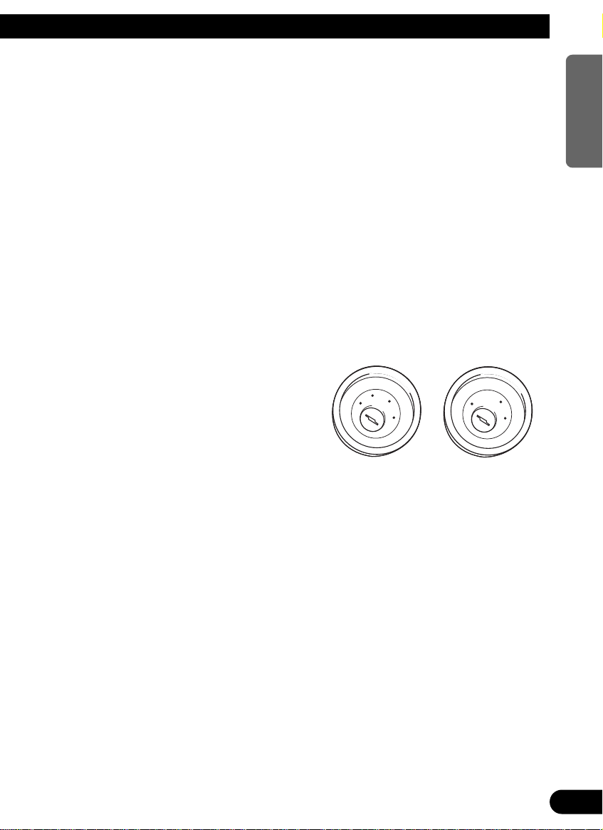
C
C
C
C
A
A
O
O
F
F
N
N
F
F
O
O
S
S
T
T
A
A
R
R
T
T
No ACC positionACC position
No ACC positionACC position
O
O
F
F
N
N
F
F
O
O
S
S
T
T
A
A
R
R
T
T
ENGLISH ESPAÑOL DEUTSCH FRANÇAIS ITALIANO NEDERLANDS
5
Page 6

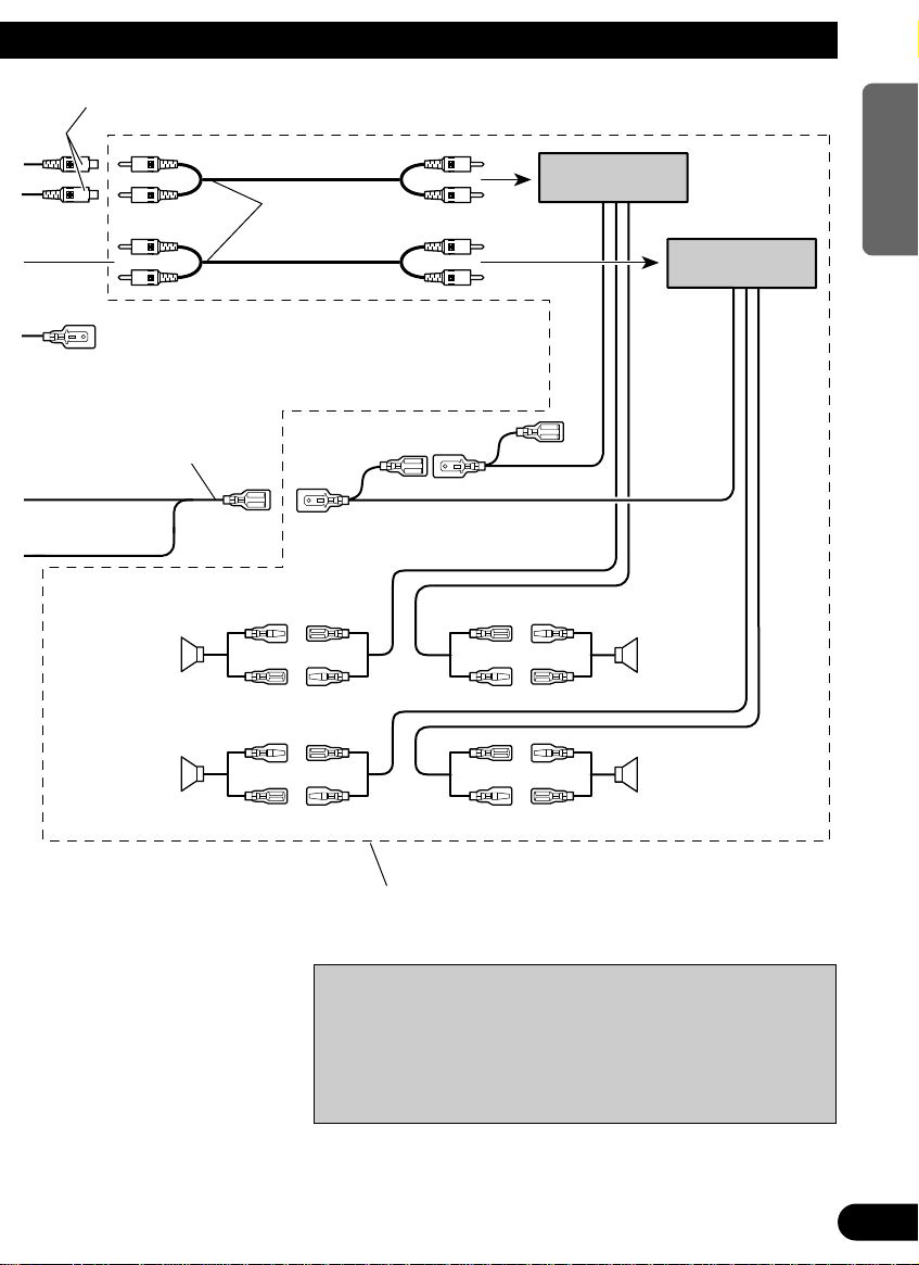
Note:
Depending on the kind of vehicle, the function
of 3* and 5* may be different. If this is the
case, be sure to connect 2* to 5* and 4* to 3*.
Speaker leads
Cap (1*)
When not using this terminal,
do not remove the cap.
ISO connector
Rear output
Fuse holder
1*
2*
4*
3*
5*
White/yellow
Antenna jack
Yellow (2*)
To terminal always supplied
with power regardless of
ignition switch position.
Red (4*)
To electric terminal controlled
by ignition switch (12 V DC)
ON/OFF.
Yellow (3*)
Back-up
(or accessory)
Red (5*)
Accessory
(or back-up)
Black (ground)
To vehicle (metal) body.
Orange
To lighting switch terminal.
Blue/white
To Auto-antenna relay control terminal.
(Max. 300 mA 12 V DC.)
Connect leads of the same
color to each other.
Note:
In some vehicles, the ISO connector may be
divided into two. If this is the case, be sure to
connect to both connectors.
See the section “RFP Alert
Installation”.
White
White/black
Gray
Gray/black
Green
Green/black
Violet
Violet/black
: Front left +
: Front left ≠
: Front right +
: Front right ≠
: Rear left +
: Rear left ≠
: Rear right +
: Rear right ≠
Multi-CD player
(sold separately)
IP-BUS input
(Blue)
IP-BUS cable
This Product
Connecting the Units
A
B
C
D
E
F
6
Page 7
Front output
ENGLISH ESPAÑOL DEUTSCH FRANÇAIS ITALIANO NEDERLANDS
A
B
C
D
Blue/white
To system control terminal of
the power amp. (Max. 300 mA
12 V DC.)
Yellow/black
If you use a cellular telephone, connect it via the Audio
Mute lead on the cellular telephone. If not, keep the Audio
Mute lead free of any connections.
E
F
Left speaker
Rear
+
≠
+
≠
Connecting cords
with RCA pin plugs
(sold separately)
Blue/white
Power amp
(sold separately)
Power amp
(sold separately)
Blue/white
Right speaker
+
FrontFront
≠
+
Rear
≠
Use this for connections when you have the separately
available amplifier.
CAUTION
• Cords for this unit and those for other units may be
different colors even if they have the same function.
When connecting this unit to another unit, refer to the
supplied Installation manuals of both units and connect cords that have the same function.
7
Page 8

RFPAlert Installation
CAUTION
• Because of the complexity of today’s technically advanced vehicle wiring systems, we recommend that your RFP Alert be installed ONLY by a professional
Pioneer installer.
Affix the included deterrent stickers to the inside of the front door windows.
Description
7 White/Yellow (DOOR SWITCH) ...................................................... (Fig. see next page)
This lead is used to trigger RFP Alert when any door is opened and may be connected to
either positive or negative (+/–) type door pin switches.
Door Switches
The RFP Alert’s door trigger input is designed to work with either positive or negative
door pin switches. After hookup, simply set door system type from RFP Alert Setting
Menu.
Domelight Delay-RFP Alert will wait for last door to close and courtesy light to turn off
before Exit Delay Timer Starts.
8
Page 9
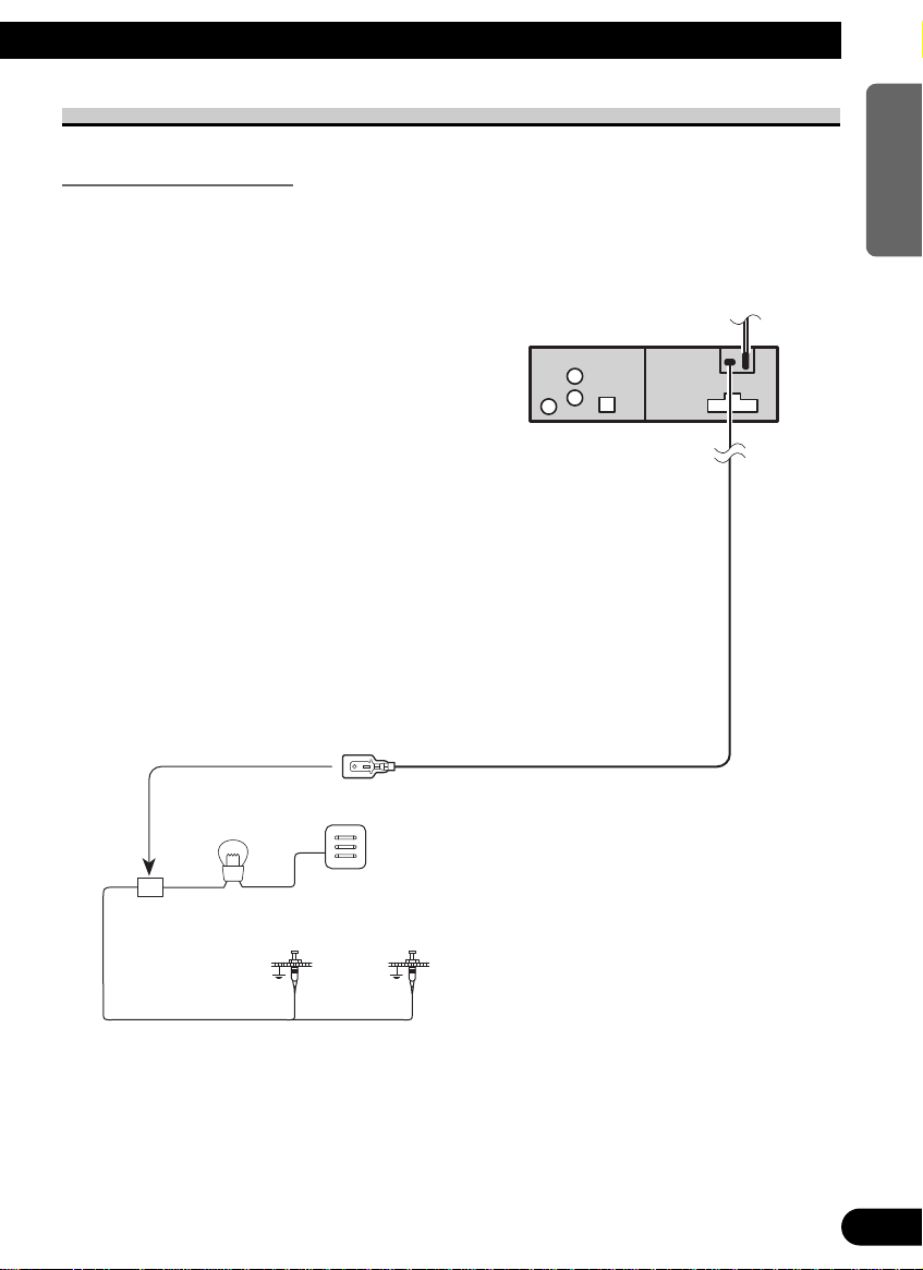
DOOR SWITCH (White/Yellow)
This Product
Fuse holder
Dome light
Factory Door Switches
White/yellow
Grounding Type Switch:
Most European, Japanese, GM and Chrysler vehicles.
Note:
• Set RFP Alert to recognize ground trigger from RFP Alert Setting Menu. Set Door System to
“DOOR-L :CLS”.
ENGLISH ESPAÑOL DEUTSCH FRANÇAIS ITALIANO NEDERLANDS
9
Page 10

RFPAlert Installation
White/yellow
This Product
Fuse holder
Dome light
Factory Door Switch
Positive (Non-grounding) Type Switch:
Jaguar, Mercedes, Ford
Note:
• Set RFP Alert to recognize positive trigger from RFP Alert Setting Menu. Set Door System to
“DOOR-H :CLS”.
Installing New Pin Switches
Separately sold pin switches are available that can be used to protect your vehicle’s trunk,
hood etc. When you purchase these, make sure that you first confirm that they can be used
with your vehicle’s door system type.
Follow the makers instructions as to installation and wiring.
10
Page 11

Installation
Note:
• Before finally installing the unit, connect the
wiring temporarily, making sure it is all connected up properly, and the unit and the system work
properly.
• Use only the parts included with the unit to ensure
proper installation. The use of unauthorized parts
can cause malfunctions.
• Consult with your nearest dealer if installation
requires the drilling of holes or other modifications of the vehicle.
• Install the unit where it does not get in the driver’s way and cannot injure the passenger if there
is a sudden stop, like an emergency stop.
• The semiconductor laser will be damaged if it
overheats, so don’t install the unit anywhere hot
— for instance, near a heater outlet.
• If installation angle exceeds 30° from horizontal,
the unit might not give its optimum performance.
30°
ENGLISH ESPAÑOL DEUTSCH FRANÇAIS ITALIANO NEDERLANDS
11
Page 12

Installation
Installation with the rubber bush
Dashboard
182
53
Holder
After inserting the holder into the dashboard, then select the appropriate tabs
according to the thickness of the dashboard material and bend them.
(Install as firmly possible using the top
and bottom tabs. To secure, bend the
tabs 90 degreees.)
Rubber bush
Screw
12
Page 13
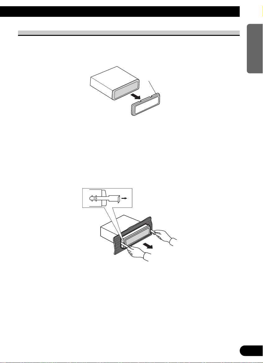
Removing the Unit
Insert the supplied extraction keys into the
unit, as shown in the figure, until they click
into place. Keeping the keys pressed against
the sides of the unit, pull the unit out.
Frame
ENGLISH ESPAÑOL DEUTSCH FRANÇAIS ITALIANO NEDERLANDS
13
Page 14

A Title (English)
FUNCTION button AUDIO button
+/– button
5/∞/2/3 buttons
BAND button PGM button
CD button
Press once to
select a CD.
ATT button
This lets you quickly
lower volume level
(by about 90%). Press
once more to return to
the original volume
level.
TUNER button
Press once to select
the tuner.
TAPEbutton
Press once to
select an MD.
PTY button
Buttons 1 – 6
TAbutton
EJECT button
Disc loading slot
AUDIO button
5/∞/2/3 buttons
FUNCTION button
SOURCE button
+/– button
BAND button
DISP button
DETACHbutton
SCROLL button
EQ button
Key Finder
Head Unit
Remote Controller (CD-R66)
The remote controller (CD-R66) enabling remote control of the head unit is sold separately. Operation is the same as when using buttons on the head unit.
14
Page 15

A Title (English)
Before Using This Product
About This Product
• This product complies with the EMC Directives (89/336/EEC, 92/31/EEC) and CE Marking
Directive (93/68/EEC).
The tuner frequencies on this product are allocated for use in Western Europe, Asia, the
Middle East, Africa and Oceania. Use in other areas may result in improper reception. The
RDS function operates only in areas with FM stations broadcasting RDS signals.
About This Manual
This product features a number of sophisticated functions ensuring superior reception and
operation. All are designed for the easiest possible use, but many are not self-explanatory.
This operation manual is intended to help you benefit fully from their potential and to
maximize your listening enjoyment.
We recommend that you familiarize yourself with the functions and their operation by
reading through the manual before you begin using this product. It is especially important
that you read and observe the “Precaution” on page 17 and in other sections.
This manual explains head unit operation. You can perform the same operations with the
remote controller (CD-R66). The remote controller enables one-touch source changing and
pause operation, and offers the convenience of ATT, a function not provided on the head
unit.
ENGLISH ESPAÑOL DEUTSCH FRANÇAIS ITALIANO NEDERLANDS
15
Page 16

Before Using This Product
About Optional Remote Controller (CD-R66)
Open the cover on the rear of the optional remote controller (CD-R66), and you’ll find a
switch. Do not change this switch’s position from the MAIN UNIT position. (Initially, the
switch is set to the MAIN UNIT position.) If you change the switch setting, correct operation of this product will not be possible.
Resetting the Microprocessor
The microprocessor must be reset under the following conditions:
When using this product for the first time after installation.
When the product fails to operate properly.
When strange (incorrect) messages appear on the display.
• To reset the microprocessor, remove the front panel as described on page 52
and press the RESET button on the head unit with a pen tip or other pointed
instrument.
16
Page 17

Precaution
• A “CLASS 1 LASER PRODUCT” label is affixed to the bottom of the player.
CLASS 1
LASER PRODUCT
• The Pioneer CarStereo-Pass is for use only in Germany.
• Keep this manual handy as a reference for operating procedures and precautions.
• Always keep the volume low enough for outside sounds to be audible.
• Protect the product from moisture.
• If the battery is disconnected, the preset memory will be erased and must be reprogrammed.
In Case of Trouble
Should this product fail to operate properly, contact your dealer or nearest authorized
Pioneer Service Station.
ENGLISH ESPAÑOL DEUTSCH FRANÇAIS ITALIANO NEDERLANDS
17
Page 18

Basic Operation
To Listen to Music
The following explains the initial operations required before you can listen to music.
Note:
• Loading a disc in this product. (Refer to page 21.)
1. Select the desired source (e.g. tuner).
Each press changes the Source ...
7 Head Unit
Each press of the SOURCE button selects the desired source in the following order:
Tuner = Built-in MD player = Multi-MD player = Multi-CD player = AUX
7 Remote Controller
Each press of the button selects the desired source in the following order:
TUNER button : Tuner = Sources OFF
CD button : Multi-CD player = Sources OFF
TAPE button : Built-in MD player = Multi-MD player = AUX = Sources OFF
Note:
• In the following cases, the sound source will not change:
* No Multi-CD player is connected to this product.
* No Multi-MD player is connected to this product.
* No disc is set in this product.
* No magazine is set in the Multi-CD player.
* No disc is set in the Multi-MD player.
* AUX (external input) is set to OFF. (Refer to page 55.)
18
Page 19
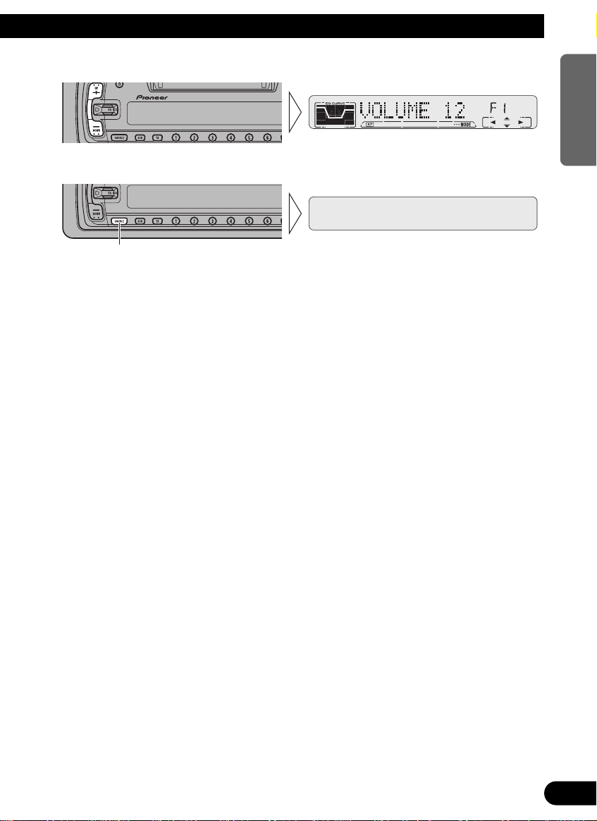
2. Raise or lower the volume.
3. Source OFF.
Hold for 1 second or more
ENGLISH ESPAÑOL DEUTSCH FRANÇAIS ITALIANO NEDERLANDS
19
Page 20
Basic Operation
Basic Operation of Tuner
This product’s AF function can be switched ON and OFF. AF should be switched OFF for
normal tuning operations.
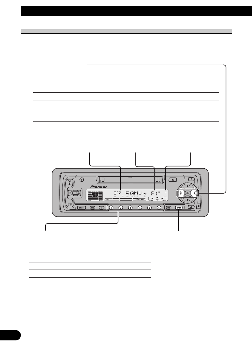
Manual and Seek Tuning
• You can select the tuning method by changing the length of time you
press the 2/3 button.
Manual Tuning (step by step) 0.5 seconds or less
Seek Tuning (automatically) Press for 0.5 seconds or more and then release.
Manual Tuning (continuously) Continue pressing for 0.5 seconds or more without releasing.
(When you release the button, Seek Tuning is selected.)
Note:
•“” stereo indicator lights when a stereo station is selected.
Frequency Indicator Band Indicator
Preset Tuning
• You can memorize broadcast stations in buttons
1 through 6 for easy, one-touch station recall.
Preset station recall 2 seconds or less
Broadcast station preset memory 2 seconds or more
Note:
• Up to 18 FM stations (6 in F1 (FM1), F2 (FM2) and F3
(FM3)) and 6 MW/LW stations can be stored in memory.
• You can also use the 5 or ∞ buttons to recall broadcast
stations memorized in buttons 1 through 6.
Preset Number Indicator
Band
F1 (FM1) = F2 (FM2)
= F3 (FM3) = MW/LW
20
Page 21
Basic Operation of Built-in MD Player
ENGLISH ESPAÑOL DEUTSCH FRANÇAIS ITALIANO NEDERLANDS
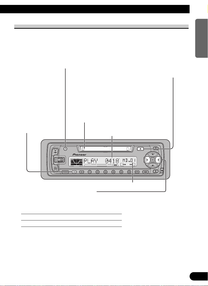
Switching the Display
Each press of the DISP button changes the display in the following order:
Playback mode (Elapsed play time)
= Disc Title = Track Title
Disc Loading Slot
You can only load one MD at a
time in the built-in MD player.
Load the MD in the direction of the
Scrolling the Display
Displayed disc and
track names are only
up to 10 letters long,
but indications can
be scrolled.
arrow, with the label side facing up.
Note:
• Load an MD after confirming the MD
shutter (refer to page 64) is closed.
Track Search and Fast Forward/Reverse
Eject
Note:
• The MD function can be turned
ON/OFF with the disc remaining in
this product. (Refer to page 18.)
• Discs left partially inserted after ejection may incur damage or fall out.
Elapsed Play Time Indicator
Track Number Indicator
• You can select between Track Search or Fast forward/Reverse by pressing
the 2/3 button for a different length of time.
Track Search 0.5 seconds or less
Fast forward/Reverse Continue pressing
Note:
• When you load a disc, this unit reads information recorded on the disc such as the number of
tracks. While the disc is being read, “TOC READ” is indicated in the display.
• If you load a disc with the arrow pointing in the wrong direction, it is automatically ejected.
• If the built-in MD player cannot operate properly, an error message (such as “ERROR-11”)
appears on the display. Refer to “Built-in MD Player’s Error Message” on page 65.
21
Page 22

Basic Operation
Basic Operation of Multi-CD Player
This product can control one or more multi-CD players. (There are some types of MultiCD players such as CDX-P630S which you cannot connect more than one.)
Track Search and Fast Forward/Reverse
• You can select between Track Search or Fast
forward/Reverse by pressing the 2/3 button
for a different length of time.
Track Search 0.5 seconds or less
Fast forward/Reverse Continue pressing
Switching the Display
Each press of the DISP button changes the display in the following order:
Playback mode (Elapsed play time) = Disc Title
Disc Number Indicator
Track Number Indicator
Elapsed Play Time Indicator
Disc Search
AA
Switching the Multi-CD Player
Using a multiple connection adapter lets
you connect up to three Multi-CD players.
M-CD 1 = M-CD 2= M-CD 3
(Displayed about for 2 seconds.)
22
Page 23

Disc Number Search (for 6-Disc, 12-Disc types)
• You can select discs directly with the 1 to 6 buttons. Just press the number
corresponding to the disc you want to listen to.
Note:
• When a 12-Disc Multi-CD Player is connected and you want to select disc 7 to 12, press the 1 to 6
buttons for 2 seconds or longer.
Disc Number Rough Search (for 50-Disc type only)
This handy function lets you select discs loaded in a 50-Disc Multi-CD Player using the 1
to 5 buttons. The 50 discs are divided into five blocks, with each of the 1 to 5 buttons
assigned to a block.
• Select the desired block with the 1 to 5 buttons.
Note:
• After completing a rough search, use the 5 and ∞ buttons to select a desired disc.
Note:
• If you switch displays when disc titles have not been input, “NO TITLE” is displayed .
• The multi-CD player may perform a preparatory operation, such as verifying the presence of a disc
or reading disc information, when the power is turned ON or a new disc is selected for playback.
“READY” is displayed.
• When a magazine is loaded into a 50-Disc type Multi-CD Player, information on all the discs in
the magazine is read.
If you start playing a disc on a 50-Disc type Multi-CD Player before reading of information on all
discs has been completed, reading of information stops part way through. This will prevent you
from using a number of functions. (If you try and use these functions, “NOT READY” is displayed.)
AA
If this happens, reading of information begins again when you switch to a component other than
the 50-Disc type Multi-CD Player.
• If the multi-CD player cannot operate properly, an error message such as “ERROR-14” is dis-
played. Refer to the multi-CD player owner’s manual.
• If there are no discs in the multi-CD player magazine, “NO DISC” is displayed.
• “LOAD” will be displayed in the following cases:
* If the disc in the extra tray in selected.
* If the disc in moved from the extra tray to the magazine.
(Refer to the 50-Disc type multi-CD player owner’s manual.)
• You cannot use the “Ejecting a Single Disc”, “Frequency Play”, “Music Group Play” or “ABC
Disc Title Search” functions with this unit.
ENGLISH ESPAÑOL DEUTSCH FRANÇAIS ITALIANO NEDERLANDS
23
Page 24

Basic Operation
z c x
z
cx
12 3
Corresponding Display Indications and Buttons
This product’s display features Key Guidance Indicators. These light to indicate which of
the 5/∞/2/3, FUNCTION and AUDIO buttons you can use. When you’re in the
Function Menu (refer to next section), Detailed Setting Menu (refer to page 27), Initial
Setting Menu (refer to page 53) or Audio Menu (refer to page 48), they also make it easy
to see which 5/∞/2/3 buttons you can use to switch functions ON/OFF, switch repeat
selections and perform other operations.
Indicator and corresponding buttons are shown below.
7Head Unit 7Remote Controller 7Display
When 1 is lit in the display, perform appropriate operations with the z buttons.
When 2 is lit in the display, it indicates that you are in the Function Menu, Detailed
Setting Menu or Initial Setting Menu. You can switch between each of these menus and
between different modes in the menus using button x on the head unit or remote controller.
When 3 is lit in the display, it indicates you are in the Audio Menu. You can switch
between modes in the Audio Menu using button c on the head unit or remote controller.
Entering the Function Menu
The Function Menu lets you operate simple functions for each source.
Note:
• After entering the Function Menu, if you do not perform an operation within about 30 seconds, the
Function Menu is automatically canceled.
1. Select the desired mode in the Function Menu. (Refer to “Function Menu
functions”.)
Each press changes the Mode ...
24
Page 25

2. Operate a mode. (e.g. Repeat Play)
The button used and the operation it performs are
indicated by the key guidance indicator. Press the
5 button to switch the key guidance indicator ON,
and the ∞ button to switch it OFF.
3. Cancel the Function Menu.
Function Menu Functions
The following chart shows functions for each source in the Function Menu.
The chart also shows indications for each function, operations and buttons used to perform
operations. For more details, or when you want to know about an operation, refer to the
page number indicated in the chart.
7Tuner
Function name (Display) Button: Operation Page
Best Stations Memory (BSM) 5:ON 29
∞:OFF
Regional Function (REG) 5:ON 32
∞:OFF
Local Seek Tuning (LOCAL) 1 5:ON 29
3 ∞:OFF
2 2 or 3:Select (Sensitivity)
TA Function (TA) 5:ON 33
∞:OFF
AF Function (AF) 5:ON 31
∞:OFF
ENGLISH ESPAÑOL DEUTSCH FRANÇAIS ITALIANO NEDERLANDS
25
Page 26

Basic Operation
7Built-in MD Player
Function name (Display) Button: Operation Page
Repeat Play (REPEAT) 5:ON 39
∞:OFF
Random Play (RANDOM) 5:ON 39
∞:OFF
Scan Play (T-SCAN) 5:ON 40
∞:OFF
Pause (PAUSE) 5:ON 40
∞:OFF
7Multi-CD Player
Function name (Display) Button: Operation Page
Repeat Modes (REPEAT) 2 or 3:Select (Play range) 41
Disc Title List (TITLE LIST) 1 2 or 3:Select (Disc Title) 47
2 5:Play
Random Play (RANDOM) 5:ON 41
∞:OFF
Scan Play (SCAN) 5:ON 42
∞:OFF
ITS Play (ITS-P) 5:ON 44
∞:OFF
Pause (PAUSE) 5:ON 43
∞:OFF
CD Sound Quality Adjustment (COMP) 5 or ∞:Select 43
(Sound Quality Function)
26
Page 27

Entering the Detailed Setting Menu
In the Detailed Setting Menu, you can operate convenient, complex functions for each
source.
1. Enter the Detailed Setting Menu.
Hold for 2 seconds
2. Select the desired mode. (Refer to “Detailed Setting Menu functions”.)
Each press changes the Mode ...
3. Operate a mode.
4. Cancel the Detailed Setting Menu.
ENGLISH ESPAÑOL DEUTSCH FRANÇAIS ITALIANO NEDERLANDS
Note:
• You can cancel the Detailed Setting Menu by pressing the FUNCTION button again for 2 seconds
or more.
27
Page 28

Basic Operation
Detailed Setting Menu Functions
The following chart shows functions for each source in the Detailed Setting Menu.
The chart also shows indications for each function, operations and buttons used to perform
operations. For more details, or when you want to know about an operation, refer to the
page number indicated in the chart.
7Tuner
Function name (Display) Button: Operation Page
Programmable Function (PGM-FUNC) 1 2 or 3:Select (Function) 61
2 5:Memory
7Built-in MD Player
Function name (Display) Button: Operation Page
Programmable Function (PGM-FUNC) 1 2 or 3:Select (Function) 61
2 5:Memory
7Multi-CD Player
Function name (Display) Button: Operation Page
Disc Title Input (TITLE IN) 1 5 or ∞:Select (Letter) 46
2 2 or 3:Select (Position)
3 3:Memory
ITS Programming (ITS) 5:Memory 44
Programmable Function (PGM-FUNC) 1 2 or 3:Select (Function) 61
2 5:Memory
28
Page 29

Tuner Operation
Local Seek Tuning (LOCAL)
When Local mode is ON, you can only select broadcast stations providing strong reception.
1. Press the FUNCTION button and select the Local mode (LOCAL) in the
Function Menu.
2. Switch the Local ON/OFF with
the 5/∞ buttons.
“LOC”
3. Select the desired Local Seek
sensitivity with the 2/3 buttons.
FM : LOCAL 1 Ô LOCAL 2 Ô LOCAL 3 Ô LOCAL 4
MW/LW: LOCAL 1 Ô LOCAL 2
Note:
• The LOCAL 4 setting allows reception of only the strongest stations, while lower settings let you
receive progressively weaker stations.
Best Stations Memory (BSM)
The BSM (Best Stations Memory) function stores stations in memory automatically.
1. Press the FUNCTION button and select the BSM mode (BSM) in the
Function Menu.
ENGLISH ESPAÑOL DEUTSCH FRANÇAIS ITALIANO NEDERLANDS
2. Switch the BSM ON with the 5
button.
The stations with the strongest signals will be stored under buttons 1–6
and in order of their signal strength.
• To cancel the process, press the
∞ button in the Function Menu
before memorization is complete.
29
Page 30

Using RDS Functions
What is RDS?
RDS (Radio Data System) is a system for transmitting data along with FM programs. This
data, which is inaudible, provides a variety of features such as: program service name, program type display, traffic announcement standby, automatic tuning and program type tuning, intended to aid radio listeners in tuning to a desired station.
Note:
• RDS service may not be provided by all stations.
• RDS functions, like AF (Alternative Frequencies search) and TA (Traffic Announcement standby),
are only active when your radio is tuned to RDS stations.
Program Service Name Display
With this function, the names of networks/stations providing RDS services replace the frequency on the display a few seconds after they are tuned in.
• When you want to know PTY Information or the frequency of the current
station, change the display.
Each press changes the Display ...
Each press of the DISP button selects the display in the following order:
Program Service Name = PTY Information = Frequency
Note:
• After switching displays, if you do not perform an operation within 8 seconds, the Program Service
Name is automatically displayed.
7 Displaying PTY Information
PTY (Program Type ID code) information for the currently tuned station appears on the
display for 8 seconds. The information is correlated with the list in the section “PTY List”
on page 38.
7 Frequency
The frequency of the current station appears on the display.
30
Page 31

AF Function (AF)
The AF (Alternative Frequencies search) function is used to search for other frequencies in
the same network as the currently tuned station. It automatically retunes the receiver to
another frequency in the network which is broadcasting a stronger signal when there are
problems with reception of the currently tuned station or better reception is possible on
a different frequency.
Note:
• AF tunes the receiver only to RDS stations when you use Seek tuning or BSM Auto Memory with
the “AF” indicator ON.
• When you recall a preset station, the tuner may update the preset station with a new frequency from
the station’s AF list. (This is only available when using presets on the FM1 band.) No preset number appears on the display if the RDS data for the station received differs from that for the originally stored station.
• Sound may be temporarily interrupted by another program during an AF frequency search.
• When the tuner is tuned to a non-RDS station, the “AF” indicator flashes.
• AF can be switched ON or OFF independently for each FM band.
Activating/Deactivating the AF Function
AF is set to ON by default.
1. Press the FUNCTION button and select the AF mode (AF) in the Function
Menu.
2. Activate or deactivate AF while in an FM band.
ENGLISH ESPAÑOL DEUTSCH FRANÇAIS ITALIANO NEDERLANDS
“AF” disappears
31
Page 32

Using RDS Functions
PI Seek Function
The tuner searches for another frequency broadcasting the same programming. “PI SEEK”
appears on the display and the radio volume is muted during a PI Seek. The muting is discontinued after completion of the PI Seek, whether or not the PI seek has succeeded. If the PI Seek
is unsuccessful, the tuner returns to the previous frequency.
PI Seek
If the tuner fails to locate a suitable alternative frequency or if the broadcasting signal is
too weak for proper reception, the PI Seek will automatically start.
Auto PI Seek (for preset station)
When preset stations cannot be recalled, as when traveling long distances, the product can
be set to perform PI Seek also during preset recall.
The default setting for Auto PI Seek is OFF.
Note:
• Refer to “Initial Setting Menu” for details on how to switch Auto PI Seek ON/OFF.
Regional Function (REG)
When AF is used to retune the tuner automatically, REG (Regional) limits the selection to
stations broadcasting regional programs.
Note:
• Regional programming and regional networks are organized differently depending on the country
(i.e., they may change according to the hour, state or broadcast area).
• The preset number may disappear on the display if the tuner tunes in a regional station which differs from the originally set station.
Activating REG
The REG function can be turned ON independently for each FM band.
1. Press the FUNCTION button and select the REG mode (REG) in the
Function Menu.
2. Activate or deactivate REG while in an FM band.
“REG”
32
Page 33

TA Function (TA)
The TA (Traffic Announcement standby) function lets you receive traffic announcements
automatically, no matter what source (tuner, built-in MD player, multi-MD player or
multi-CD player) you are listening to. The TA function can be activated for either a TP station (a station that broadcasts traffic information) or an EON TP station (a station carrying
information which cross-references TP stations).
Activating/Deactivating the TA Function
1. Tune in a TP or EON TP station.
The “TP” indicator lights when the tuner is tuned to a TP station, and both the “EON” and
“TP” indicators light when it is tuned to an EON TP station.
2. Activate the TA function.
“TA”
The “TA” indicator lights, indicating that the tuner is waiting for traffic announcements.
Repeat the preceding operation when no traffic announcement is being received to deacti-
vate the TA function.
Note:
• You can also switch the TA Function ON/OFF in the Function Menu.
• The system switches back to the original source following traffic announcement reception.
• The TA function can be activated from the built-in MD player, multi-MD player or multi-CD player mode if the tuner was last set to the FM band but not if it was last set to the MW/LW band.
• If the tuner was last set to FM, turning on the TA function lets you operate other tuning functions
while listening to an MD or a CD.
• Only TP or EON-TP stations are tuned in during the Seek Tuning mode when the “TA” indicator is
ON.
• Only TP or EON-TP stations are stored by BSM when the “TA” indicator is ON.
ENGLISH ESPAÑOL DEUTSCH FRANÇAIS ITALIANO NEDERLANDS
33
Page 34

Using RDS Functions
Canceling Traffic Announcements
• Press the TA button while a traffic announcement is being received to cancel
the announcement and return to the original source.
The announcement is canceled but the tuner remains in the TA mode until the TA button is
pressed again.
Adjusting the TA Volume
When a traffic announcement begins, the volume adjusts automatically to a preset level to
enable you to hear the announcement clearly.
• Set the volume by adjusting it during reception of a traffic announcement.
The newly set volume is stored in memory and recalled for subsequent traffic announcements.
TP Alarm Function
About 30 seconds after the “TP” or “EON” indicator is extinguished due to a weak signal,
a 5 second beep sounds to remind you to select another TP or EON-TP station.
• If you are listening to the tuner, tune in another TP station or EON-TP station.
In the built-in MD player, multi-MD player or multi-CD player mode, the tuner automatically seeks out the TP station with the strongest signal in the current area 10 (or 30)* seconds after “TP” disappears from the display.
* Time taken before Seek begins.
TA function ON 10 seconds
TA, AF functions ON 30 seconds
34
Page 35

PTY Function
With Wide and Narrow classification of program type, the PTY function provides two
ways to select stations by the type of program being broadcast (PTY Search). It also provides automatic tuning to emergency broadcasts (PTY Alarm).
Note:
• There’s no need to perform PTY Search settings again if they have previously been set. After
switching to the PTY Search Setting mode in Step 1, just perform PTY Search in Step 4.
Searching the PTY
1. Select the PTY Search Setting mode.
2. Select the PTY Search method (Wide, Narrow).
3. Select one from among the PTY.
ENGLISH ESPAÑOL DEUTSCH FRANÇAIS ITALIANO NEDERLANDS
35
Page 36

Using RDS Functions
4. Start PTY Search.
The tuner searches for a station broadcasting the desired PTY.
To cancel the PTY Search Setting mode, hold down the PTY button for 2 seconds or more.
Note:
• If a PTY code of zero is received from a station, “NONE” will be displayed. This indicates that the
station has not defined its program contents.
• If the signal is too weak for this product to pick up the PTY code, “NO PTY” will be displayed.
• The program of some stations may differ from that indicated by the transmitted PTY.
• If no station broadcasting the selected programming type is found, “NOT FOUND” is displayed for
about 2 seconds, and the tuner returns to the original station.
News Program Interruption Setting
You can switch automatic reception of PTY code news programs ON/OFF. When a
received news program ends, reception of the previous program resumes.
• Set interruption to ON or OFF.
36
“NEWS”Hold for 2 seconds
Page 37

PTY Alarm
PTY Alarm is a special PTY code for announcements regarding emergencies such as natural disasters. When the tuner receives the radio alarm code, “ALARM” appears on the
display and the volume adjusts to the TA volume. When the station stops broadcasting the
emergency announcement, the system returns to the previous source.
Note:
• The system switches back to the original source following emergency announcement reception.
Canceling Emergency Announcements
• Press the TA button during emergency announcement reception to cancel
the announcement and return to the previous source.
ENGLISH ESPAÑOL DEUTSCH FRANÇAIS ITALIANO NEDERLANDS
37
Page 38

Using RDS Functions
PTY List
Wide Narrow Details
News&Inf News News.
Affairs Current affairs.
Info General information and advice.
Sport Sports programs.
Weather Weather reports/Meteorological information.
Finance Stock market reports, commerce, trading etc.
Popular Pop Mus Popular music.
Rock Mus Contemporary modern music.
Easy Mus Easy listening music.
Oth Mus Other types of music, which can’t be
categorized.
Jazz Jazz music based programs.
Country Country music based programs.
Nat Mus National music based programs.
Oldies Oldies music, ‘Golden age’ based programs.
Folk Mus Folk music based programs.
Classics L. Class Light classical music.
Classic Serious classical music.
Others Educate Educational programs.
Drama All radio plays and serials.
Culture Programs concerned with any aspect of national
or regional culture.
Science Programs about nature, science and technology.
Varied Light entertainment programs.
Children Children’s programs.
Social Social affairs programs.
Religion Religion affairs programs or services.
Phone In Phone in based programs.
Touring Travel programs, not for announcements about
traffic problem.
Leisure Programs about hobbies and recreational
activities.
Document Documentary programs.
38
Page 39

Using the Built-in MD Player
Repeat Play (REPEAT)
Repeat Play plays the same track repeatedly.
1. Press the FUNCTION button and select the Repeat mode (REPEAT) in the
Function Menu.
2. Switch Repeat Play ON/OFF
with the 5/∞ buttons.
Note:
• If you perform Track Search or Fast forward/Reverse, Repeat Play is automatically canceled.
Random Play (RANDOM)
Random Play plays the tracks on an MD in random order for variety.
1. Press the FUNCTION button and select the Random mode (RANDOM) in
the Function Menu.
2. Switch Random Play ON/OFF
with the 5/∞ buttons.
ENGLISH ESPAÑOL DEUTSCH FRANÇAIS ITALIANO NEDERLANDS
39
Page 40

Using the Built-in MD Player
Scan Play (T-SCAN)
Scan Play plays the first 10 seconds or so of each track on an MD in succession.
1. Press the FUNCTION button and select the Scan mode (T-SCAN) in the
Function Menu.
2. Switch the Scan mode ON with
the 5 button.
3. When you find the desired
track, cancel scan play with the
∞ button.
If the Function Menu is automatically canceled at this time, select the
Scan mode in the Function Menu
once more.
Note:
• Scan Play is canceled automatically after all the tracks on a disc have been scanned.
Pause (PAUSE)
Let’s you pause play of the track currently playing.
1. Press the FUNCTION button and select the Pause mode (PAUSE) in the
Function Menu.
2. Switch the Pause ON/OFF with
the 5/∞ buttons.
40
Page 41

Using Multi-CD Players
Repeat Modes (REPEAT)
There are four repeat modes (play range): One-track Repeat, Disc Repeat, Multi-CD player
Repeat (the selected Multi-CD player) and All Repeat (all Multi-CD players). (Default
mode is Multi-CD player Repeat.)
1. Press the FUNCTION button and select the Repeat Selecting mode
(REPEAT) in the Function Menu.
2. Select the desired Repeat Mode
with the 2/3 buttons.
Multi-CD player Repeat (“MCD” is
displayed) = All Repeat (“ALL” is
displayed) = One-track Repeat
(“TRK” is displayed and “RPT” indicator lights) = Disc Repeat (“DSC”
is displayed and “DISC” indicator
lights)
Note:
• All Repeat is available only when two or more multi-CD players are installed.
• If you go beyond the play range of the selected repeat mode by performing Track Search, Fast forward/Reverse or selecting another disc or Multi-CD player, the mode changes to an applicable
Repeat mode.
Random Play (RANDOM)
Tracks are played at random within the selected repeat mode play range as explained in
“Repeat Modes” above.
ENGLISH ESPAÑOL DEUTSCH FRANÇAIS ITALIANO NEDERLANDS
1. Press the FUNCTION button and select the Random mode (RANDOM) in
the Function Menu.
2. Switch the Random Play
ON/OFF with the 5/∞
buttons.
After selecting the desired repeat
mode play range from those referred
to in “Repeat Modes” above, switch
Multi-CD Player Random Play ON.
41
Page 42

Using Multi-CD Players
Scan Play (SCAN)
In the Disc Repeat Mode, the beginning of each track on a single disc is scanned for about
10 seconds. In the Multi-CD player Repeat and All Repeat modes, the beginning of the
first track on each disc is scanned for about 10 seconds.
1. Press the FUNCTION button and select the Scan mode (SCAN) in the
Function Menu.
2. Switch the Scan Play ON with
the 5 button.
After selecting the desired repeat mode
play range from those referred to in
“Repeat Modes” on page 41, switch
Multi-CD Player Scan Play ON.
3. When you find the desired
track (or disc), cancel scan play
with the ∞ button.
If the Function Menu is automatically canceled at this time, select the
Scan mode in the Function Menu
once more.
Display Play range
TRACK SCAN Disc Repeat
DISC SCAN Multi-CD player Repeat
SCAN All Repeat
Note:
• Scan Play is canceled automatically after all the tracks or discs have been scanned.
42
Page 43

Pause (PAUSE)
Let’s you pause play of the track currently playing.
1. Press the FUNCTION button and select the Pause mode (PAUSE) in the
Function Menu.
2. Switch the Pause ON/OFF with
the 5/∞ buttons.
CD Sound Quality Adjustment (COMP)
Using the COMP (Compression) and DBE (Dynamic Bass Emphasis) functions enables
Multi-CD player sound quality adjustment. Both of the functions enable adjustment on two
levels.
7 COMP
The COMP (Compression) function
eliminates distortions caused by imbalances between loud and subdued sounds
at higher volumes.
1. Press the FUNCTION button and select the COMP/DBE Switching mode
(COMP) in the Function Menu.
2. Select the desired mode with
the 5/∞ buttons.
COMP OFF = COMP 1 = COMP 2
= COMP OFF = DBE 1 = DBE 2
7 DBE
DBE (Dynamic Bass Emphasis) boosts
bass levels to give a fuller sound.
ENGLISH ESPAÑOL DEUTSCH FRANÇAIS ITALIANO NEDERLANDS
Note:
• You can use these functions with Multi-CD players that have them. If the player does not feature
the COMP/DBE functions, “NO COMP” is displayed if you try to use them.
43
Page 44

Using Multi-CD Players
ITS (Instant Track Selection)
The ITS function allows you to search for the track you wish to play when one or more
multi-CD players are installed. You can use ITS to program automatic playback of up to
24 tracks per disc from up to 100 discs. (You can store ITS program and Disc Title data for
up to 100 discs in memory.)
ITS Programming (ITS)
ITS programming can be conducted in any multi-CD player playback mode except ITS
play.
1. Play the track you wish to program.
2. Select the ITS Programming mode (ITS) in the Detailed Setting Menu.
(Refer to page 27.)
3. Program the desired track with
the 5 button.
Note:
• After 100 discs have been programmed, data for a new disc will overwrite the data for the disc that
has not been played back for the longest time.
ITS Play (ITS-P)
ITS play of tracks is performed within the play range explained in the “Repeat Modes”
section.
1. Press the FUNCTION button and select the ITS Play mode (ITS-P) in the
Function Menu.
2. Switch ITS play ON/OFF with
the 5/∞ buttons.
After selecting the desired repeat
mode play range from those referred
to in “Repeat Modes”on page 41,
switch ITS play ON.
Note:
• If no track in the current range is programmed for ITS play “ITS EMPTY” is displayed.
44
Page 45

Erase a Track Program
1. Select the track you wish to erase, during ITS play.
2. Select the ITS Programming mode (ITS) in the Detailed Setting Menu.
(Refer to page 27.)
3. Erase with the ∞ button.
ITS is canceled and playback of the
next ITS-programmed track begins.
If there are no more programmed
tracks in the current range, “ITS
EMPTY” is displayed and normal
play resumes.
Erase a Disc Program
1. Select the disc you wish to erase, while the disc is playing.
2. Select the ITS Programming mode (ITS) in the Detailed Setting Menu.
(Refer to page 27.)
3. Erase with the ∞ button.
ENGLISH ESPAÑOL DEUTSCH FRANÇAIS ITALIANO NEDERLANDS
45
Page 46

Using Multi-CD Players
Disc Title
Disc Title Input (TITLE IN)
You can input Titles up to 10 letters long for up to 100 discs. Using this function lets you
easily search for and select a desired disc for play. (You can store ITS program and Disc
Title data for up to 100 discs in memory.)
1. Play the disc you wish to input the disc title.
2. Select the Disc Title Input mode (TITLE IN) in the Detailed Setting Menu.
(Refer to page 27.)
3. Switch the Alphabet modes.
Each press of button 1 changes the mode in the following order:
Alphabet (Upper case), Numbers and Symbols = Alphabet (Lower case)
= European letters, such as those with accents (e.g. á, à, ä, ç)
Note:
• You can switch to the Numbers and Symbol mode by pressing button 2.
4. Select letters, numbers and
symbols with the 5/∞ buttons.
To insert a space, select the flashing
cursor “_”.
5. Move the box left and right
with the 2/3 buttons.
46
Page 47

6. When you have completed title
input, make the 10th letter
flash, then memorize by pressing the 3 button.
Note:
• Titles remain in memory, even after the disc has been removed from the magazine, and are recalled
when the disc is reinserted.
• After the titles for 100 discs have been entered, data for a new disc will overwrite the data for the
disc that has not been played back for the longest time. If a Multi-CD player is installed, the data is
stored in the Multi-CD player’s memory.
• You can display the disc title of the disc currently playing. For details, refer to “Switching the
Display” on page 22.
Disc Title List (TITLE LIST)
Follow the procedures below to play a disc for which you have input the title in a multiCD player:
1. Press the FUNCTION button and select the Disc Title List mode
(TITLE LIST) in the Function Menu.
2. Each time you press the 2/3
buttons, titles in the current
disc magazine are displayed in
the order of their disc numbers.
Nothing is displayed for disc whose
titles have not been input.
ENGLISH ESPAÑOL DEUTSCH FRANÇAIS ITALIANO NEDERLANDS
3. Select the desired disc for playback by pressing 5 button
when its title is displayed.
47
Page 48

Audio Adjustment
Ea
Selecting the Equalizer Curve
You can switch between Equalizer curves.
• Move the EQ button up or down to select the desired Equalizer curve.
Equalizer curve
POWERFUL += NATURAL += VOCAL += CUSTOM += EQ FLAT
+= SUPER BASS
Note:
• “CUSTOM” stores an equalizer curve you have made adjustments to. (Refer to “Equalizer Curve
Adjustment” on page 49.)
• If you make adjustments when a curve other than “CUSTOM” is selected, the adjusted curve is
stored in memory as a “CUSTOM” curve. Also, the displayed curve switches to that selected before
adjustments were made.
• You can create different “CUSTOM” curves for different sources. (The built-in MD player and
multi-MD player are set to the same Equalizer Curve Adjustment setting automatically.)
Entering the Audio Menu
With this Menu, you can adjust the sound quality.
Note:
• After entering the Audio Menu, if you do not perform an operation within about 30 seconds, the
Audio Menu is automatically canceled.
1. Select the desired mode in the Audio Menu.
Each press changes the Mode ...
2. Operate a mode.
3. Cancel the Audio Menu.
48
Page 49

Audio Menu Functions
The Audio Menu features the following functions.
Balance Adjustment (FADER)
This function allows you to select a Fader/Balance setting that provides ideal listening conditions in all occupied seats.
1. Press the AUDIO button and select Fader/Balance mode (FADER) in the
Audio Menu.
2. Adjust front/rear speaker balance with the 5/∞ buttons.
“FADER F15” – “FADER R15” is
displayed as it moves from front to
rear.
3. Adjust left/right speaker balance with the 2/3 buttons.
“BAL L 9” – “BAL R 9” is displayed
as it moves from left to right.
Note:
• “FADER 0” is the proper setting when 2 speakers are in use.
Equalizer Curve Adjustment (EQ-LOW/MID/HIGH)
You can adjust equalizer curve settings as desired. Adjusted equalizer curve settings are
memorized in “CUSTOM”.
ENGLISH ESPAÑOL DEUTSCH FRANÇAIS ITALIANO NEDERLANDS
1. Press the AUDIO button and select the Equalizer mode
(EQ-LOW/MID/HIGH) in the Audio Menu.
2. Select the band you want to
adjust with the 2/3 buttons.
EQ-LOW += EQ-MID += EQ-HIGH
3. Boost or attenuate the selected
band with the 5/∞ buttons.
The display shows “+6” – “–6”.
49
Page 50

Audio Adjustment
Level (dB)
Q=2W
Q=2N
Center frequency
Frequency (Hz)
Ea
Equalizer Curve Fine Adjustment
You can adjust the center frequency of each equalizer curve band (LOW/MID/HIGH) and
the Q factor (curve characteristics).
1. When in the Audio Menu, press the AUDIO button for 2 or more seconds to
select Equalizer Curve Fine Adjustment.
2. Press the AUDIO button to
select the desired band for
adjustment.
3. Select the desired frequency
with the 2/3 buttons.
LOW: 40 += 80 += 100 += 160 (Hz)
MID: 200 += 500 += 1K += 2K (Hz)
HIGH: 3K += 8K += 10K += 12K
(Hz)
4. Select the desired Q factor with
the 5/∞ buttons.
2N += 1N += 1W += 2W
Loudness Adjustment (LOUD)
The Loudness function compensates for deficiencies in the low and high sound ranges at
low volume. You can select a desired Loudness level.
1. Press the AUDIO button and select the Loudness mode (LOUD) in the Audio
Menu.
2. Switch the Loudness function
ON/OFF with the 5/∞ buttons.
3. Select the desired level with the
2/3 buttons.
LOW += MID += HI
50
Page 51

Front Image Enhancer Function (FIE)
The F.I.E. (Front Image Enhancer) function is a simple method of enhancing front imaging
by cutting mid- and high-range frequency output from the rear speakers, limiting their output to low-range frequencies. You can select the frequency you want to cut.
Precaution:
• When the F.I.E. function is deactivated, the rear speakers output sound in all frequencies, not only
bass sounds. Reduce the volume before disengaging F.I.E. to prevent a sudden increase in volume.
1. Press the AUDIO button and select the F.I.E. mode (FIE) in the Audio
Menu.
2. Switch the F.I.E. function
ON/OFF with the 5/∞ buttons.
3. Select the desired frequency
with the 2/3 buttons.
100 += 160 += 250 (Hz)
Note:
• After switching the F.I.E. function ON, select the Fader/Balance mode in the Audio Menu, and
adjust front and rear speaker volume levels until they are balanced.
• Switch the F.I.E. function OFF when using a 2-speaker system.
ENGLISH ESPAÑOL DEUTSCH FRANÇAIS ITALIANO NEDERLANDS
Source Level Adjustment (SLA)
The SLA (Source Level Ajustment) function prevents radical leaps in volume when
switching between sources. Settings are based on the FM volume, which remains
unchanged. (Since the FM volume is the control, SLA is not possible in the FM modes.)
The MW/LW, MD, CD and AUX levels can all be adjusted.
The built-in MD player and multi-MD player are set to the same volume adjustment setting automatically.
1. Compare the FM volume with the volume of the other source.
(e.g. Built-in MD player)
2. Press the AUDIO button, and select the SLA mode (SLA) in the Audio
Menu.
3. Increase or decrease the level
with the 5/∞ buttons.
The display shows “+4” – “–4”.
51
Page 52

Detaching and Replacing the Front Panel
Theft Protection
The front panel of the head unit is detachable to discourage theft.
Detaching the Front Panel
1. Eject the front panel.
2. To remove the front panel,
pull its right-hand side
toward you.
Take care not to grip it tightly or
drop it.
3. Use the protective case provided to store/carry the
detached front panel.
Replacing the Front Panel
• Replace the front panel by
clipping it into place.
Precaution:
• Never use force or grip the display tightly when removing or replacing the front panel.
• Avoid subjecting the front panel to excessive shocks.
• Keep the front panel out of direct sunlight and high temperatures.
Warning Tone
If the front panel is not detached within 5 seconds after the ignition is turned off, a warning
tone will sound.
Note:
• You can cancel the warning tone function. (Refer to page 55.)
52
Page 53

Initial Setting
Entering the Initial Setting Menu
With this Menu, you can perform initial settings for the product.
1. Switch the sources OFF.
2. Enter the Initial Setting Menu with the sources OFF.
Hold for 2 seconds
3. Select the desired mode.
Each press changes the Mode ...
4. Operate a mode.
5. Cancel the Initial Setting Menu.
ENGLISH ESPAÑOL DEUTSCH FRANÇAIS ITALIANO NEDERLANDS
Note:
• ALARM is a new feature of the “Removable Front Panel Alert”. Refer to “RFP Alert
Function” for details and instructions on how to use this function.
• Holding down the FUNCTION button for 2 seconds also cancels the Initial Setting Menu.
53
Page 54

Initial Setting
Initial Setting Menu Functions
The Initial Setting Menu features the following functions.
Setting the Time
This is the mode for setting the time on the unit’s clock display. (Refer to page 61 for
details concerning the clock display.)
1. Select the time setting mode in the Initial Setting Menu.
2. Select “Hour” or “Minute”
with the 2/3 buttons.
3. Set as desired time with the
5/∞ buttons.
As soon as you switch to “Minute”,
the seconds start counting from 00.
Changing the FM Tuning Step (FM STEP)
Normally set at 50 kHz during Seek tuning in the FM mode, the tuning step changes to
100 kHz when the AF or TA mode is activated.
It may be preferable to set tuning step to 50 kHz in the AF mode.
1. Press the FUNCTION button and select the FM Tuning Step mode (FM
STEP) in the Initial Setting Menu.
2. Select the desired tuning step
with the 2/3 buttons.
Note:
• The tuning step remains set at 50 kHz during Manual tuning.
• The tuning step returns to 100 kHz if the battery is temporarily disconnected.
54
Page 55

Switching the Auto PI Seek (A-PI)
During Preset Station PI Seek operation, you can switch the Auto PI Seek function
ON/OFF. (Refer to “PI Seek Function” on page 32.)
1. Press the FUNCTION button and select the Auto PI Seek mode (A-PI) in the
Initial Setting Menu.
2. Switch the Auto PI Seek
ON/OFF with the 5/∞ buttons.
Setting the Warning Tone (WARN)
You can switch the Warning Tone function ON/OFF. (Refer to “Warning Tone” on page
52.)
1. Press the FUNCTION button and select the Warning mode (WARN) in the
Initial Setting Menu.
2. Switch the Warning tone
ON/OFF with the 5/∞ buttons.
Switching the AUX Mode (AUX)
It is possible to use auxiliary (AUX) equipment with this product.
Activate the AUX mode when using external equipment with this product.
ENGLISH ESPAÑOL DEUTSCH FRANÇAIS ITALIANO NEDERLANDS
1. Press the FUNCTION button and select the AUX Setting mode (AUX) in the
Initial Setting Menu.
2. Switch the AUX ON/OFF with
the 5/∞ buttons.
55
Page 56

Initial Setting
Setting the Dimmer (DIMMER)
To enable this product’s display from being too bright at night, when the vehicle’s head
lights are turned ON the display is dimmed. You can switch this function ON/OFF.
1. Press the FUNCTION button and select the Dimmer mode (DIMMER) in
the Initial Setting Menu.
2. Switch the Dimmer ON/OFF
with the 5/∞ buttons.
Selecting the Illumination Color (ILL. CLR)
This product is equipped with two illumination colors, green and red.
You can select the desired illumination color.
1. Press the FUNCTION button and select the Illumination Color mode (ILL.
CLR) in the Initial Setting Menu.
2. Select the desired illumination
color with the 2/3 buttons.
56
Page 57

RFPAlert Function
In addition to the Removable Front Panel, Pioneer has incorporated a new feature
“Removable Front Panel Alert”. This feature is designed to protect your new Pioneer car
stereo as well as your vehicle contents.
Activating the RFP Alert Feature
Pioneer has developed a menu display that allows you to set-up your RFP Alert to meet
your personal needs. By scrolling through this menu it is possible to select your own
“Entry Delay Time”, “Speaker Output Volume” and “Door System Type”.
Initially from the factory the RFP Alert feature is not activated.
1. Select the RFP Alert Feature
ON/OFF mode (ALARM) in
the Initial Setting Menu. (Refer
to page 53.)
2. Press the 5 button to switch
the RFP Alert Feature ON.
Press the ∞ button to deactivate the
RFP Alert Feature.
3. Press the FUNCTION button
for 2 seconds to set the RFP
Alert Setting menu.
ENGLISH ESPAÑOL DEUTSCH FRANÇAIS ITALIANO NEDERLANDS
Setting Entry Delay Time
Initially the “Entry Delay Time” is set to 15 seconds. The “Entry Delay Time” can be
adjusted to be 0, 5, 15, 30, 45 or 60 seconds.
1. Decrease or increase the “Entry
Delay Time” with the 2/3 buttons.
2. Press the FUNCTION button
to move to the next selection.
57
Page 58

RFPAlert Function
Activating Internal Speaker ON/ OFF
This feature allows you to select whether or not the speaker output is sounded when the
“RFP Alert” is triggered. Initially from the factory the speaker output is activated.
Toggling between 5, ∞ buttons allows you to deactivate or activate the “Internal
Speaker”. If you switch the speaker output OFF, you can not change the “TEST MODE”.
Speaker Volume Output Adjustment
If the “Internal Speaker Output” has been selected then it is possible to adjust the volume
of the speaker output for when the Alert is triggered. To adjust the volume you must
engage the “TEST MODE”.
Note:
• If the “Internal Speaker Output” is turned OFF, then this menu will not appear.
1. Select the “TEST MODE” with
the 3 button.
2. Press the 5 button to switch
the “TEST MODE” ON.
In this mode the speakers will sound.
3. Decrease or increase the volume with the volume buttons.
Display shows 10 – 30.
4. After setting volume with the ∞
button, cancel the “TEST
MODE”, then move to the next
selection.
5. Cancel the “TEST MODE”
with the 2 button.
6. Press the FUNCTION button
to move to the next selection.
58
Page 59

Selecting Door Switching Systems
It is necessary to select the correct “Door System Type” (Negative or Positive switching)
for that of your vehicle. Initially, the system is set for vehicles with the grounding type
(Negative switching).
Select the correct “Door system type” of your vehicle from below.
ENGLISH ESPAÑOL DEUTSCH FRANÇAIS ITALIANO NEDERLANDS
7 Vehicles to select “DOOR-L :CLS”
EUROPEAN, JAPANESE, GM,
CHRYSLER
7 Vehicles to select “DOOR-H :CLS”
JAGUAR, MERCEDES*, FORD, etc.
* Some Models Only.
• Select “DOOR-L :CLS” or
“DOOR-H :CLS” with the
2/3 buttons.
Door System Confirmation
The door system confirmation feature was incorporated to ensure that the correct door system type has been selected. (e.g. Set to “DOOR-H :CLS” for JAGUAR vehicles.)
1. First, close all the vehicle’s
doors. If the correct door system type has been selected then
the Display will show “DOORH :CLS”.
If not, select the alternative door system type by pressing the
button. Lastly, confirm each door
triggers the Alert by opening and
closing each vehicle’s door.
2. As the vehicle’s door is opened
the display should change
accordingly (“DOOR-H :CLS”
– “DOOR-H :OPN”).
3. Press the BAND button and
cancel the RFP Alert Setting
Menu.
Setting of the “RFP Alert” is now
complete.
[ or ]
Note:
• In case that the battery is disconnected or the RESET button is pressed, it may be necessary to
reprogram the RFP Alert Menu; otherwise this setting needs to be done only once.
59
Page 60

RFPAlert Function
Operation of “RFP Alert”
Providing the installation and setting of the “RFP Alert Setting Menu” has been performed
correctly, operation of the “RFP Alert” is very simple.
Arming Alert
To arm your Alert simply turn off the ignition and detach the front panel, as described on
page 52. After detaching the front panel the “RFP Alert” will automatically arm itself after
30 seconds, providing all of the doors are closed. If after 30 seconds, a door still remains
open the RFP Alert will not arm until the last door has been closed. After closing all of the
doors, ensure that they are securely locked. The LED indicator on the head unit will flash
as a visual deterrent. Your vehicle is now protected by your “RFP Alert”.
Disarming Alert
Upon entering your vehicle, and within the “Entry Delay Time” set within the “RFP Alert
Menu”, attach your Pioneer Front Panel as described on page 52.
If you have forgotten your removable front panel, simply insert the ignition key in the ignition and turn the key from “OFF” to “ON” within the “Entry Delay Time”.
Entry Detection
If the “RFP Alert” was not disarmed in accordance with “Disarming Alert”, the “RFP
Alert” will be triggered. The “RFP Alert” will sound for 60 seconds and will repeat 5 times
if any door is left open or reopened. After the fifth time the “RFP Alert” will reset to prevent continuous sounding and prevent your battery from discharging.
Precaution:
• Upon returning to your vehicle and before opening any doors, check to see if the LED indicator
is still flashing. If the LED is no longer flashing, it indicates that the Alert as sounded.
Disarming, as described above, is still necessary.
60
Page 61

Other Functions
Time Display
Displaying the Time
• To turn the time display ON with the source ON.
Hold for 2 seconds
The time display disappears temporarily when you perform another operation, but the time
indication returns to the display after 25 seconds.
Using the PGM Button (PGM-FUNC)
The PGM (Programmable) button can memorize one of the functions in the Function
Menu.
It is possible to memorize a different function for each source.
Setting the PGM Button
1. Select the PGM button’s setting mode (PGM-FUNC) in the Detailed Setting
Menu. (Refer to page 27.)
ENGLISH ESPAÑOL DEUTSCH FRANÇAIS ITALIANO NEDERLANDS
Hold for 2 seconds
2. Select the function you want to memorize in the PGM button.
3. Memorize the function in PGM button.
Pressing the BAND button cancels the Detailed Setting Menu.
61
Page 62

Other Functions
Using the PGM Button
The PGM button operates in a different way depending on the function programmed
(memorized).
• Use the PGM button.
PGM button operations are only possible with the remote control.
7Tuner
Function Name (Display) Press Hold for 2 seconds
Best Stations Memory (BSM) OFF ON
Regional Function (REG) ON/OFF –––––
Local Seek Tuning (LOCAL) ON/OFF Entering the Local Seek
Sensitivity mode
7Built-in MD Player
Function Name (Display) Press Hold for 2 seconds
Pause (PAUSE) ON/OFF –––––
Repeat Play (REPEAT) ON/OFF –––––
Random Play (RANDOM) ON/OFF –––––
7Multi-CD Player
Function Name (Display) Press Hold for 2 seconds
Pause (PAUSE) ON/OFF –––––
Repeat Modes (REPEAT) Selecting the mode –––––
Random Play (RANDOM) ON/OFF –––––
Disc Title Input (LIST) Enter the LIST mode –––––
ITS (ITS) ITS Programming ON/OFF
62
Page 63

Using the AUX Source
It is possible to use auxiliary (AUX) equipment with this product.
To listen to auxiliary equipment, switch the AUX Mode in the Initial Setting Menu ON,
and then select the desired source.
Selecting the AUX Source
• Select AUX. (Refer to page 18.)
Each press changes the Source ...
AUX Title Input
The display title for AUX Source can be changed.
1. Select the Aux Title Input mode (TITLE IN) in the Detailed Setting Menu.
Hold for 2 seconds
2. Input the Aux Title.
Refer to “Disc Title Input” on page 46, and perform procedures 3 to 6 in the same way.
ENGLISH ESPAÑOL DEUTSCH FRANÇAIS ITALIANO NEDERLANDS
Cellular Telephone Muting
Sound from this system is muted automatically when a call is made or received using a
cellular telephone connected to this product.
• The sound is turned off, “MUTE” is displayed and no audio adjustment except volume
control is possible. Operation returns to normal when the phone connection is ended.
63
Page 64

MD Player and Care
Shutter
Precaution
• Do not open the MD shutter by hand. Forcing it open may result in damage.
• Be sure to stick labels supplied with MDs in the specified location. Failing to do this, or
sticking one label on top of another may make it impossible for the MD to be removed.
• Do not use MDs with labels that are not affixed correctly. Labels like this may catch on
something, preventing removal of the MD. Before using an MD, remove the label if it is
not correctly affixed, and replace it with a new label.
• Keep MDs out of direct sunlight and high temperatures.
• If the surface of an MD cartridge is dirty, wipe it gently with a clean, soft cloth.
• Do not apply benzene, thinner or other volatile liquids to MDs.
• When it’s cold, if you start playing an MD immediately after switching the heater in a
room on, condensation on the optical lens inside the player or on the MD may prevent
normal play. If this happens, turn off the player for about an hour to allow the condensation to evaporate, and wipe damp MD cartridge surfaces with a soft cloth.
64
Page 65

Built-in MD Player’s Error Message
When problems occur with MD playback, an error message appears on the display. Refer
to the table below to identify the problem, then take the suggested corrective action. If the
error persists, contact your dealer or your nearest PIONEER Service Center.
Message Possible cause Recommended action
NO D-DATA Disc name has not been input. Switch to a display other than Disc
Name indications.
NO TR-DATA Track name has not been input. Switch to a display other than
Track Name indications.
HEAT MD player overheating. Discontinue play until the machine
temperature drops.
ERROR- 11, 12, 17, 30 Dirty disc. Clean the disc.
ERROR- 11, 12, 17, 30 Scratched disc. Replace the disc.
ERROR- 01, 11,12, Electrical or mechanical Turn the ignition ON and OFF, or
17, 30, A0 problem. switch to a different source, then back
to the MD player.
ERROR- 20, 21 Track information cannot be Reload the MD.
read.
ERROR- 20, 21, 22, 24 There is something wrong with Replace the disc.
the MD.
ERROR- 23 The MD contains recorded Replace the disc.
information other than music.
ERROR- A1 Electrical or mechanical Press the Reset botton.
problem.
ERROR- MD play not possible. Replace the MD with another disc,
or press the Reset button.
ENGLISH ESPAÑOL DEUTSCH FRANÇAIS ITALIANO NEDERLANDS
65
Page 66

Specifications
General
Power source .......... 14.4 V DC (10.8 – 15.1 V allowable)
Grounding system ........................................ Negative type
Max. current consumption ...................................... 10.0 A
Dimensions
(mounting size) ...... 178 (W)
(front face) .............. 188 (W) × 58 (H) × 18 (D) mm
Weight ...................................................................... 1.3 kg
× 50 (H) × 150 (D) mm
Amplifier
Maximum power output ...................................... 40 W × 4
Continuous power output .................................... 25 W × 4
Load impedance .......................... 4 Ω (4 – 8 Ω allowable)
Preout output level/output impedance ........ 500 mV/1 kΩ
Equalizer (3-Band Parametric Equalizer)
(Low) .......................... Frequency: 40/80/100/160 Hz
(Mid) .......................... Frequency: 200/500/1k/2k Hz
(High) ................ Frequency: 3.15k/8k/10k/12.5k Hz
Loudness contour
(Low) .................. +3.5 dB (100 Hz), +3 dB (10 kHz)
(Mid) ................ +10 dB (100 Hz), +6.5 dB (10 kHz)
(High) ................ +11 dB (100 Hz), +11 dB (10 kHz)
(DIN45324, +B = 14.4 V)
Q Factor: 0.35/0.59/0.95/1.15
(+6 dB when boosted)
Level: ±12 dB
Q Factor: 0.35/0.59/0.95/1.15
(+6 dB when boosted)
Level: ±12 dB
Q Factor: 0.35/0.59/0.95/1.15
(+6 dB when boosted)
Level: ±12 dB
(volume: –30 dB)
(volume: –30 dB)
(volume: –30 dB)
MD player
System ................................ Mini disc digital audio system
Usable discs ........................................................ Mini disc
Signal format .................... Sampling frequency: 44.1 kHz
Number of quantization bits: 16; linear
Frequency characteristics ............ 20 – 20,000 Hz (±1 dB)
Signal-to-noise ratio ...... 94 dB (1 kHz) (IEC-A network)
Dynamic range ............................................ 93 dB (1 kHz)
Number of channels ............................................ 2 (stereo)
FM tuner
Frequency range ...................................... 87.5 – 108 MHz
Usable sensitivity
.................. 11 dBf (1.0 µV/75 Ω, mono, S/N: 30 dB)
50 dB quieting sensitivity .... 16 dBf (1.7 µV/75 Ω, mono)
Signal-to-noise ratio ...................... 70 dB (IEC-A network)
Distortion .......................... 0.3% (at 65 dBf, 1 kHz, stereo)
Frequency response ...................... 30 – 15,000 Hz (±3 dB)
Stereo separation .......................... 40 dB (at 65 dBf, 1 kHz)
MW tuner
Frequency range ...................................... 531 – 1,602 kHz
Usable sensitivity .............................. 18 µV (S/N: 20 dB)
Selectivity .................................................. 50 dB (±9 kHz)
LW tuner
Frequency range ........................................ 153 – 281 kHz
Usable sensitivity .............................. 30 µV (S/N: 20 dB)
Selectivity .................................................. 50 dB (±9 kHz)
66
Note:
• US and foreign patents licensed from Dolby
Laboratories Licensing Corporation.
• Specifications and the design are subject to possi-
ble modification without notice due to improvements.
Page 67

ENG/MASTER 98
67
Page 68

PIONEER ELECTRONIC CORPORATION
4-1, Meguro 1 chome, Meguro-ku, TOKYO, 153-8654, JAPAN
PIONEER ELECTRONICS (USA) INC.
P.O. Box 1760, Long Beach, California 90801, U.S.A.
TEL: (800) 421-1404
PIONEER ELECTRONIC (EUROPE) N.V.
Haven 1087 Keetberglaan 1, 9120 Melsele, Belgium
TEL: (0) 3/570.05.11
PIONEER ELECTRONICS AUSTRALIA PTY. LTD.
178-184 Boundary Road, Braeside, Victoria 3195, Australia
TEL: (03) 580-9911
PIONEER ELECTRONICS OF CANADA, INC.
300 Allstate Parkway Markham, Ontario L3R 0P2, Canada
TEL: (905) 479-4411
PIONEER ELECTRONICS DE MEXICO, S.A. de C.V.
San Lorenzo Num 1009 3er piso Desp. 302
Col. Del Valle, Mexico D.F. C.P. 03100
TEL: 5-688-52-90
<98H00F0R01>
Published by Pioneer Electronic Corporation.
Copyright © 1998 by Pioneer Electronic
Corporation. All rights reserved.
Publicado por Pioneer Electronic Corporation.
Copyright © 1998 Pioneer Electronic Corporation.
Todos los derechos reservados.
Printed in Japan
Impreso en Japón
<CRD2736-A> EW
 Loading...