


INSTALLATION MANUAL
KEH-P8900R KEH-P8900R-W
This product conforms to new cord colors.
Los colores de los cables de este producto se conforman con un nuevo código de colores.
Dieses Gerät entspricht den neuen kabelfarben.
Le code de couleur des câbles utilisé pour ce produit est nouveau.
Questo prodotto è conforme ai nuovi codici colori.
De kleuren van de snoeren van dit toestel zijn gewijzigd.
MANUEL |
ESPAÑOL ENGLISH |
D’INSTALLATION |
NEDERLANDS ITALIANO FRANÇAIS DEUTSCH |
|
|

Contents |
|
Connecting the Units ................................ |
2 |
RFP Alert Installation ................................ |
6 |
Description ........................................................ |
6 |
Door Switches .................................................. |
6 |
DOOR SWITCH (White/yellow) ...................... |
7 |
-Grounding Type Switch:
-Positive (Non-grounding) Type Switch:
-Installing New Pin Switches
Installation .................................................. |
9 |
Installation with the rubber bush ...................... |
9 |
Removing the Unit .......................................... |
10 |
Installing the |
|
Steering Remote Control Unit ........ |
11 |
Installing the Unit on a |
|
Left-Hand-Drive Car ................................ |
12 |
1
Connecting the Units
Note:
•This unit is for vehicles with a 12-volt battery and negative grounding. Before installing it in a recreational vehicle, truck, or bus, check the battery voltage.
•To avoid shorts in the electrical system, be sure to disconnect the ≠ battery cable before beginning installation.
•Refer to the owner’s manual for details on connecting the power amp and other units, then make connections correctly.
•Secure the wiring with cable clamps or adhesive tape. To protect the wiring, wrap adhesive tape around them where they lie against metal parts.
•Route and secure all wiring so it cannot touch any moving parts, such as the gear shift, handbrake, and seat rails. Do not route wiring in places that get hot, such as near the heater outlet. If the insulation of the wiring melts or gets torn, there is a danger of the wiring short-circuiting to the vehicle body.
•Don’t pass the yellow lead through a hole into the engine compartment to connect to the battery. This will damage the lead insulation and cause a very dangerous short.
•Do not shorten any leads. If you do, the protection circuit may fail to work when it should.
•Never feed power to other equipment by cutting the insulation of the power supply lead of the unit and tapping into the lead. The current capacity of the lead will be exceeded, causing overheating.
•When replacing fuse, be sure to use only fuse of the rating prescribed on the fuse holder.
•Since a unique BPTL circuit is employed, never wire so the speaker leads are directly grounded or the left and right ≠ speaker leads are common.
•The black lead is ground. Please ground this lead separately from the ground of high-current products such as power amps.
If you ground the products together and the ground becomes detached, there is a risk of damage to the products or fire.
•If the RCA pin jack on the unit will not be used, do not remove the caps attached to the end of the connector.
•Speakers connected to this unit must be highpower types with minimum rating of 45 W and impedance of 4 to 8 ohms. Connecting speakers with output and/or impedance values other than those noted here may result in the speakers catching fire, emitting smoke, or becoming damaged.
•When this product’s source is switched ON, a control signal is output through the blue/white lead. Connect to an external power amp’s system remote control or the car’s Auto-antenna relay control terminal (max. 300 mA 12 V DC). If the car features a glass antenna, connect to the antenna booster power supply terminal.
•When an external power amp is being used with this system, be sure not to connect the blue/white lead to the amp’s power terminal. Likewise, do not connect the blue/white lead to the power terminal of the auto-antenna. Such connection could cause excessive current drain and malfunction.
•To avoid short-circuiting, cover the disconnected lead with insulating tape. Especially, insulate the unused speaker leads without fail. There is a possibility of short-circuiting if the leads are not insulated.
•To prevent incorrect connection, the input side of the IP-BUS connector is blue, and the output side is black. Connect the connectors of the same colors correctly.
•If this unit is installed in a vehicle that does not have an ACC (accessory) position on the ignition switch, the red lead of the unit should be connected to a terminal coupled with ignition switch ON/OFF operations. If this is not done, the vehicle battery may be drained when you are away from the vehicle for several hours. (Fig. 1)
|
|
CC |
|
|
|
|
|
|
|
|
|
F |
A |
O |
|
|
|
F |
O |
|
|
|
|
N |
|
F |
N |
|||||
O |
F |
|
|
|
|
O |
|
|
|
|
|
|
|
|
S |
|
|
|
S |
||
|
|
|
|
|
|
|
|
|
||
|
|
|
|
|
T |
|
|
|
|
T |
|
|
|
|
R |
A |
|
|
|
R |
A |
|
|
|
T |
|
|
|
T |
|
||
|
|
|
|
|
|
|
|
|
||
ACC position |
No ACC position |
|||||||||
Fig. 1
•Cords for this product and those for other products may be different colors even if they have the same function. When connecting this product to another product, refer to the supplied Installation manuals of both products and con-
nect cords that have the same function.
NEDERLANDS ITALIANO FRANÇAIS DEUTSCH ESPAÑOL ENGLISH
2
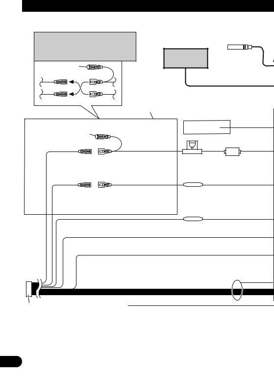
Connecting the Units
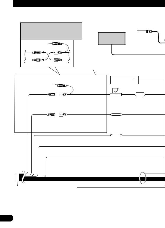
Note: |
Antenna jack |
|
Depending on the kind of vehicle, the function |
||
|
||
of 3* and 5* may be different. In this case, be |
|
|
sure to connect 2* to 5* and 4* to 3*. |
Multi-CD player |
|
1* |
(sold separately) |
|
|
3* 2*
IP-BUS cable
5* 4*
Connect leads of the same color to each other.
See the section “RFP Alert Installation”.
Cap (1*)
When not using this terminal, do not remove the cap.
Yellow (3*) |
Yellow (2*) |
Back-up |
To terminal always supplied |
(or accessory) |
with power regardless of |
|
ignition switch position. |
White/yellow
Fuse holder
Red (5*)
Accessory (or back-up)
Red (4*) |
Fuse resistor |
To electric terminal controlled |
|
by ignition switch (12 V DC) |
|
ON/OFF. |
|
Orange |
Fuse resistor |
To lighting switch terminal. |
|
Black (ground) |
|
To vehicle (metal) body. |
|
ISO connector
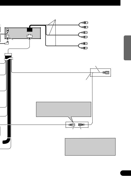
Note:
In some vehicles, the ISO connector may be divided into two. In this case, be sure to connect to both connectors.
Yellow/black
If you use a cellular telephone, connect it via the Audio Mute lead on the cellular telephone. If not, keep the Audio Mute lead free of any connections.
3
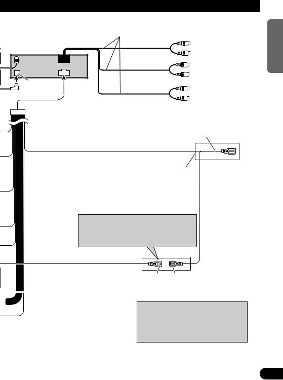
RCA output
Refer to “Connecting to a sold separately Power Amp”.
This Product
IP-BUS input (Blue)
Blue/white
To system control terminal of
the power amp (max. 300 mA 12 V DC).
Refer to “Connecting to a
Sold Separately Power Amp”.
The pin position of the ISO connector will differ depends on the type of vehicle. Connect 6* and 7* when Pin 5 is an antenna control type. In another type of vehicle, never connect 6* and 7*.
|
|
|
Blue/white (6*) Blue/white (7*) |
|
|
|
|
|
To Auto-antenna relay control |
|
|
Speaker leads |
terminal (max. 300 mA 12 V DC). |
|
|
|
|
||
|
|
White |
: Front left + |
|
|
|
|||
|
|
White/black : Front left ≠ |
Note: |
|
|
||||
|
|
Gray |
: Front right + |
|
|
|
When a subwoofer is connected to this unit |
||
|
|
Gray/black |
: Front right ≠ |
|
|
|
instead of a rear right speaker, do not connect the |
||
|
|
Green |
: Rear left + or Not Used |
|
|
|
rear left speaker lead to anything. For details, refer |
||
|
|
Green/black : Rear left ≠ or Not Used |
||
|
|
to the Initial Setting Menu in the Operation |
||
|
|
Violet |
: Rear right + or Subwoofer + |
|
|
|
Manual. |
||
|
|
Violet/black : Rear right ≠ or Subwoofer ≠ |
|
|
Fig. 2
NEDERLANDS ITALIANO FRANÇAIS DEUTSCH ESPAÑOL ENGLISH
4

Connecting the Units
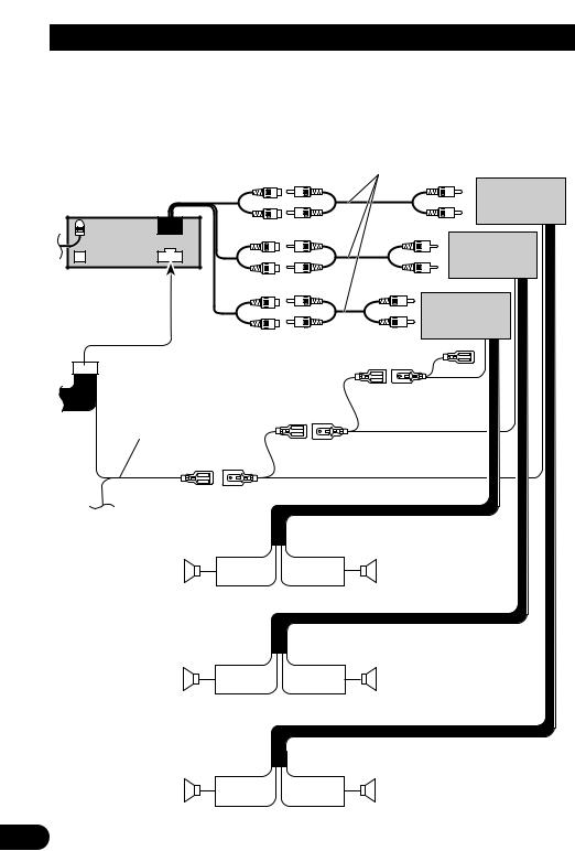
7 Connecting to a Sold Separately Power Amp
This product can be connected to a sold separately power amp using the RCA output jacks.
Connecting cords with RCA pin plugs
(sold separately)
Front output
Rear output
This Product
Subwoofer or Non-Fading output
Blue/white
To system control terminal of the power amp
(max. 300 mA 12 V DC).
System remote control
Left
+
Subwoofer
≠
Left
++
Rear speaker
≠≠
Left
++
Front speaker
≠≠
Power amp (sold separately)
Power amp (sold separately)
Power amp (sold separately)
Right
Subwoofer
Right
Rear speaker
Right
Front speaker
Fig. 3
5

RFP Alert Installation
 CAUTION
•Because of the complexity of today’s technically advanced vehicle wiring systems, we recommend that your RFP Alert be installed ONLY by a professional Pioneer installer.
Affix the included deterrent stickers to the inside of the front door windows.
Description
7 White/yellow (DOOR SWITCH) ........................................................................ |
(Fig. 4 & 5) |
This lead is used to trigger RFP Alert when any door is opened and may be connected to either positive or negative (+/–) type door pin switches.
Door Switches
The RFP Alert’s door trigger input is designed to work with either positive or negative door pin switches. After hookup, simply set door system type from RFP Alert Setting Menu.
Domelight Delay-RFP Alert will wait for last door to close and courtesy light to turn off before Exit Delay Timer Starts.
NEDERLANDS ITALIANO FRANÇAIS DEUTSCH ESPAÑOL ENGLISH
6

RFP Alert Installation
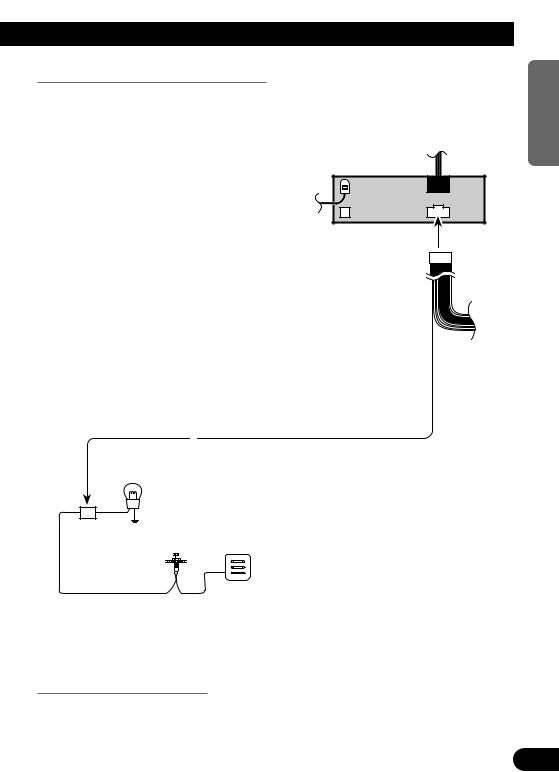
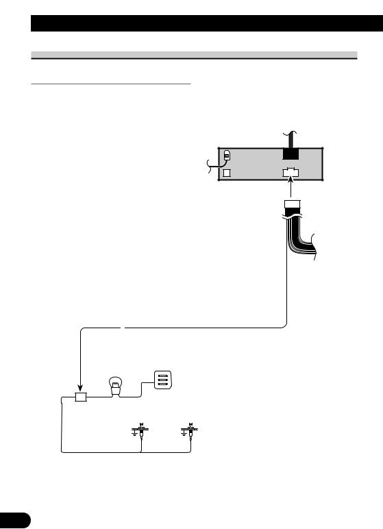
DOOR SWITCH (White/yellow)
Grounding Type Switch:
Most European, Japanese, GM and Chrysler vehicles.
Note:
•Set RFP Alert to recognize ground trigger from RFP Alert Setting Menu. Set Door System to “Door System: Negative, Current mode: Close”.
This Product
White/yellow
Fuse holder
Dome light
Factory Door Switches
Fig. 4
7
Positive (Non-grounding) Type Switch:
Jaguar, Mercedes, Ford
Note:
•Set RFP Alert to recognize positive trigger from RFP Alert Setting Menu. Set Door System to “Door System: Positive, Current mode: Close”.
This Product
White/yellow
Dome light
Factory Door Switch
Fuse holder
Fig. 5
Installing New Pin Switches
Separately sold pin switches are available that can be used to protect your vehicle’s trunk, hood etc. When you purchase these, make sure that you first confirm that they can be used with your vehicle’s door system type.
Follow the makers instructions as to installation and wiring.
NEDERLANDS ITALIANO FRANÇAIS DEUTSCH ESPAÑOL ENGLISH
8
Installation
Note:
•Before finally installing the unit, connect the wiring temporarily, making sure it is all connected up properly, and the unit and the system work properly.
•Use only the parts included with the unit to ensure proper installation. The use of unauthorized parts can cause malfunctions.
•Consult with your nearest dealer if installation requires the drilling of holes or other modifications of the vehicle.
•Install the unit where it does not get in the driver’s way and cannot injure the passenger if there is a sudden stop, like an emergency stop.
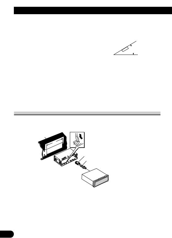
•If installation angle exceeds 30° from horizontal, the unit might not give its optimum performance. (Fig. 6)
 30°
30°
Fig. 6
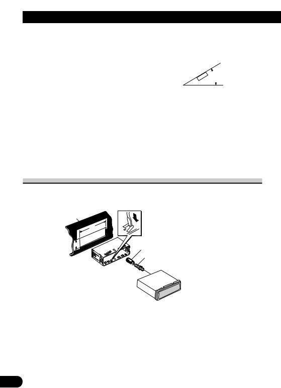
Installation with the rubber bush
Dashboard
182
53
Holder
After inserting the holder into the dashboard, then select the appropriate tabs according to the thickness of the dashboard material and bend them.
(Install as firmly as possible using the top and bottom tabs. To secure, bend the tabs 90 degrees.)
Rubber bush
Screw
Fig. 7
9
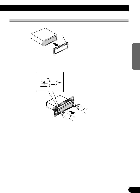
Removing the Unit
Frame
Pull out to remove the frame.
(When reattaching the frame, point the side with a groove downwards and attach it.)
Fig. 8
Insert the supplied extraction keys into the unit, as shown in the figure, until they click into place. Keeping the keys pressed against the sides of the unit, pull the unit out.
Fig. 9
NEDERLANDS ITALIANO FRANÇAIS DEUTSCH ESPAÑOL ENGLISH
10
Installing the Steering Remote Control Unit
 WARNING
•Avoid installing this unit in such a location where the operation of safety devices such as airbags is prevented by this unit. Otherwise, there is a danger of a fatal accident.
•Avoid installing this unit in such a location where the operation of the steering wheel and the gearshift lever may be prevented. Otherwise, it may result in a traffic accident.
 CAUTION
•Installation of this unit requires specialized skills and experience. Installation of this unit should be entrusted to a dealer from whom you purchased this unit.
•Install this unit using only the parts supplied with this unit. If other parts are used, this unit may be damaged or could dismount itself, which leads to an accident or trouble.
•Install this unit as required by this manual. Failure to do so may cause an accident.
•Do not install this unit near the doors where rainwater is likely to be spilled on the unit. Incursion of water into the unit may cause smoke or fire.
 WARNING
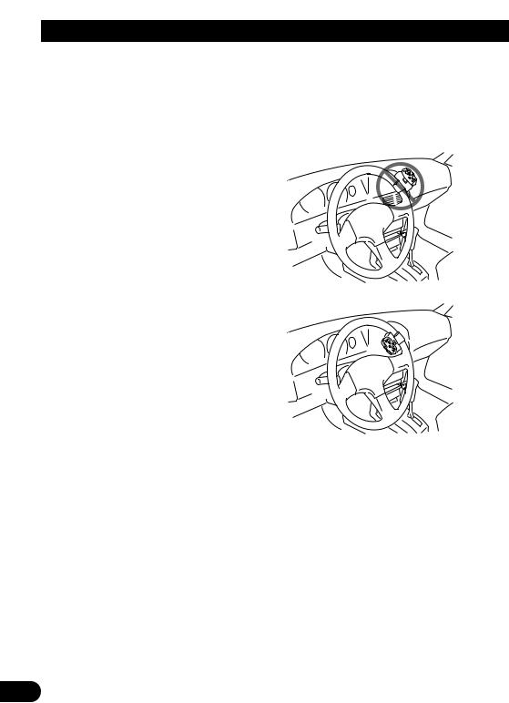
•Fix this unit securely to the steering wheel with the belt attached to the unit. If this unit is loose, it disturbs driving stability, which may result in a traffic accident.
•Do not attach this unit to the outer circumference of the steering wheel. Otherwise, it disturbs driving stability, causing a traffic accident. Always attach this unit to the inner circumference of the steering wheel as shown. (Fig. 10)
Note:
•Do not install this unit in such a place as may obstruct the driver’s view.
•Since interior layout differs depending on the type of vehicle, the ideal installation location for the unit also differs. When installing the unit, select a location that assures optimum transmission of signals from the unit to the car stereo.
Fig. 10
11
Installing the Unit on a Left-Hand Drive Car
Note:
•When the unit is installed on a right-hand-drive car, the horizontal positions are inverted.
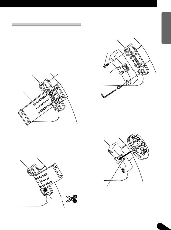
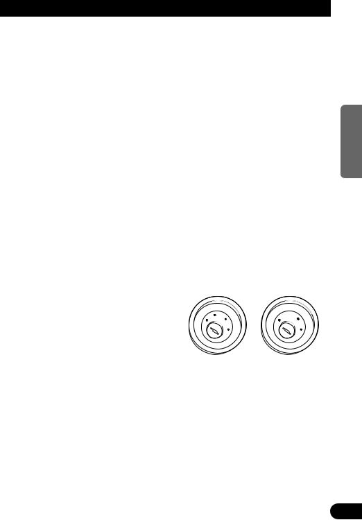
1.Secure inner holder to the inner circumference of the steering wheel with belt. (Fig. 11)
•Fit the inner holder to the steering wheel so that the arrow-marked side faces the driver as shown below.
Inner holder
Belt
Fig. 11
2.Cut the extra portion of the belt at the center of the inner holder. (Fig. 12)
•Keep the cut-off portion of the belt as a spare.
Fig. 12
3.Install outer holder on the inner holder and secure with screws. (Fig. 13)
•Tighten the screws with the supplied hexagonal wrench.
Screw
Outer holder
Fig. 13
4.Install the remote control unit in the holder. (Fig. 14)
•When removing the remote control unit from the holder, move the corrugated release section toward the steering wheel and slide the remote control unit toward you.
Release Section
Fig. 14
NEDERLANDS ITALIANO FRANÇAIS DEUTSCH ESPAÑOL ENGLISH
12

Contenido |
|
Conexión de las unidades ........................ |
2 |
Instalación de alerta RFP ........................ |
6 |
Descripción ........................................................ |
6 |
Interruptores de puerta ...................................... |
6 |
Interruptor de puerta (DOOR SWITCH) |
|
(Blanco/amarillo) ........................................ |
7 |
-Interruptor de tipo de conexión a masa:
-Interruptor de tipo positivo (sin conexión a masa):
-Instalando los interruptores de clavija nuevos
Instalación .................................................. |
9 |
Instalación con tope de goma ............................ |
9 |
Extracción de la unidad .................................. |
10 |
Instalación de la unidad de control |
|
remoto de dirección .......................... |
11 |
Instalación de la unidad en |
|
el coche de manejo del lado izquierdo ...... |
12 |
1
Conexión de las unidades
Nota:
•Esta unidad es para vehículos con batería de 12 voltios y con conexión a tierra. Antes de instalar la unidad en un vehículo recreativo, camioneta, o autobús, revise el voltaje de la batería.
•Para evitar cortocircuitos en el sistema eléctrico, asegúrese de desconectar el cable de la batería ≠ antes de comenzar con la instalación.
•Consulte con el manual del usuario para los detalles sobre la conexión de la alimentación de amperios y de otras unidades, luego haga las conexiones correctamente.
•Asegure el cableado con abrazaderas de cables o con cinta adhesiva. Para proteger el cableado, envuélvalo con cinta adhesiva donde éstos se apoyan sobre las piezas de metal.
•Coloque y asegure todo el cableado de tal manera que no toque las piezas en movimiento, tal como la palanca de cambio de velocidades, el freno de mano, y los pasamanos de los asientos. No coloque el cableado en lugares que se calientan, tal como cerca de la salida de un calefactor. Si el material aislante del cableado se derritiera o se gastara, habrá el peligro de un cortocircuito del cableado a la carrocería del vehículo.
•No pase el conductor amarillo a través de un orificio en el compartimiento del motor para conectar a la batería. Esto dañará el material aislante del conductor y causará un cortocircuito peligroso.
•No acorte ningún conductor. Si lo hiciera, la protección del circuito podría fallar al funcionar cuando debería.
•Nunca alimente energía a otros equipos cortando el aislamiento del conductor de alimentación provista de la unidad y haciendo un empalme con el conductor. La capacidad de corriente del conductor se excederá, causando el recalentamiento.
•Cuando reemplace algún fusible, asegúrese de utilizar solamente un fusible del ratio descrito en el soporte de fusibles.
•Ya que se emplea un circuito único BPTL, nunca coloque los cables de manera que los conductores del altavoz estén directamente en conexión a tierra o que el altavoz izquierdo y derecho ≠ sean comunes.
•El conductor negro es la masa. Conecte a masa este conductor separadamente desde la masa de los productos de alta corriente tal como los amplificadores de potencia.
Si conecta juntos a masa los productos y la masa se desconecta, se crea el riesgo de daños a los productos o de incendios.
•Si la toma de clavija RCA en la unidad no se usa, retire las tapas fijadas al extremo del conector.
•Los altavoces conectados a esta unidad deberán ser del tipo de alta potencia, teniendo un régimen mínimo de 45 W y una impedancia de 4 a 8 ohmios. La conexión de altavoces con valores de impedancia y/o de salida diferentes a los anotados aquí podrían causar fuego, emisión de humo o daños a los altavoces.
• Cuando se conecta la fuente de este producto, una |
ENGLISH |
||||||||||
señal de control se emite a través del conductor |
|||||||||||
|
|||||||||||
azul/blanco. Conecte al control remoto de sistema |
|
||||||||||
de un amplificador de potencia externo o al termi- |
|
||||||||||
nal de controle de relé de antena automática del |
|
||||||||||
vehículo (máx. 300 mA 12 V CC). Si el vehículo |
|
||||||||||
tiene una antena en vidrio, conecte al terminal de |
|
||||||||||
suministro de energía de la antena. |
|
|
|
|
|||||||
• Cuando se está utilizando un amperio de potencia |
|
||||||||||
externa con este sistema, asegúrese de no conectar |
ESPAÑOL |
||||||||||
el conductor azul/blanco al terminal de potencia |
|||||||||||
• Para evitar cortocircuitos, cubra el conductor |
|||||||||||
de amperios. Asimismo, no conecte el conductor |
|
||||||||||
azul/blanco al terminal de potencia de la auto- |
|
||||||||||
antena. Tal conexión podría causar la fuga de cor- |
|
||||||||||
riente excesiva y causar fallos de funcionamiento. |
|
||||||||||
desconectado con cinta aislada. Especialmente, |
|
||||||||||
aísle los conductores de altavoz no usados. Hay la |
|
||||||||||
posibilidad de cortocircuito si no se aíslan los |
|
||||||||||
conductores. |
|
|
|
|
|
|
|
|
DEUTSCH |
||
• Para evitar la conexión incorrecta, el lado de en- |
|||||||||||
tiene una posición ACC (accesorio) en el interrup- |
|||||||||||
trada del conector IP-BUS es azul, y el lado de |
|
||||||||||
salida es negro. Conecte los conectores del mismo |
|
||||||||||
color correctamente. |
|
|
|
|
|
|
|||||
• Si se instala esta unidad en un vehículo que no |
|
||||||||||
tor de encendido, el conductor rojo de la unidad |
|
||||||||||
deberá conectarse al terminal conectado con las |
|
||||||||||
operaciones del interruptor de encendido |
|
|
|
||||||||
ON/OFF. Si no se hace esto, la batería del |
|
FRANÇAIS |
|||||||||
vehículo podría drenarse cuando usted esté lejos |
|||||||||||
|
|||||||||||
del vehículo por varias horas. (Fig. 1) |
|
|
|
|
|||||||
|
CC |
|
|
|
|
|
|
|
|
|
|
|
A |
O |
|
|
|
F |
O |
|
|
|
|
|
F |
|
|
|
|
|
|
||||
|
N |
|
N |
|
|||||||
O |
F |
|
|
|
O |
F |
|
|
|
|
|
|
|
|
S |
|
|
S |
|
||||
|
|
|
|
|
|
|
|
||||
|
|
|
|
T |
|
|
|
|
T |
|
|
|
|
|
R |
A |
|
|
|
R |
A |
|
|
|
|
T |
|
|
|
T |
|
|
|||
Posición ACC |
No en la posición ACC |
ITALIANO |
|||||||||
|
|||||||||||
|
|
|
|
|
|
|
|
|
Fig. 1 |
|
|
|
|
||||||||||
• Los cables para este producto y aquéllas para |
|
||||||||||
otros productos pueden ser de colores diferentes |
NEDERLANDS |
||||||||||
aun si tienen la misma función. Cuando se conec- |
|||||||||||
ta este producto a otro, refiérase a los manuales |
|||||||||||
|
|||||||||||
de instalación de ambos productos y conecte los |
|
||||||||||
cables que tienen la misma función. |
|
|
|
|
|||||||
|
|
|
|
|
|
|
|
|
|
|
|
2
Conexión de las unidades
Nota:
Jack para antena
Dependiendo del tipo del vehículo, la función
de 3* y 5* puede ser diferente. En este caso, |
Reproductor de |
||||
asegúrese de conectar 2* a 5* y 4* a 3*. |
|||||
Multi-CD (en venta |
|||||
|
|
|
|||
1* |
|
|
por separado) |
||
|
|
|
|
||
3* |
2* |
|
|
|
|
|
|
|
|
Cable IP-BUS |
|
5* |
4* |
|
Conecte los conductores |
|
|
|
|
|
del mismo color uno a |
Vea la sección |
|
|
|
|
otro. |
||
|
|
|
“Instalación de alerta RFP”. |
||
|
|
|
|
||
Tapa (1*) |
|
|
|
Blanco/amarillo |
|
Cuando este terminal no se |
|
|
|
||
|
|
|
|
||
usa, no retire la tapa. |
|
|
|
|
|
Amarillo (3*) |
Amarillo (2*) |
|
Portafusible |
||
Reserva |
|
Al terminal con suministro constante |
|
||
(o accesorio) |
de electricidad, independientemente |
|
|||
de la posición del interruptor de |
|
||||
|
|
|
|||
encendido.
Rojo (5*) Accesorio (o reserva)
Rojo (4*)
Al terminal de energía eléctrica controlado por el interruptor de encendido del vehículo
(12 V CC) ON/OFF.
Resistencia de fusible
Anaranjado |
Resistencia |
Al terminal de interruptor |
de fusible |
de iluminación. |
|
Negro (masa)
A la carrocería del veículo (parte metálica).
Conector ISO
Nota:
Amarillo/negro
En algunos vehículos, el conector ISO puede
Si utiliza un teléfono celular, conéctelo por el cable de
estar dividido en dos partes. En este caso,
enmudecimiento de audio del teléfono celular. Si no,
asegúrese de conectar a ambos conectores.
mantenga el enmudecimiento de audio libre de cualquier conexión.
3
Salida RCA
Vea “Conectando a un amplificador de potencia vendido separadamente”.
Este producto
Entrada IP-BUS (Azul)
Azul/blanco
Al terminal de control de sistema del amp. de potencia (máx. 300 mA 12 V CC).
Vea “Conectando a un amplificador de potencia vendido separadamente”.
La posición de los pinos del conector ISO difiere de acuerdo al tipo de vehículo. Conecte 6* y 7* cuando el pino 5 es un tipo de control de antena. En otros tipos de vehículo, nunca conecte 6* y 7*.
Azul/blanco (6*) Azul/blanco (7*)
|
|
|
|
Al terminal de control de relé de antena |
|
|
Cables de altavoz |
automática (máx. 300 mA 12 V CC). |
|
|
|
Nota: |
||
|
|
Blanco |
: Izquierdo delantero + |
|
|
|
Blanco/negro : Izquierdo delantero ≠ |
Cuando se conecta un altavoz de graves secundario |
|
|
|
a esta unidad en lugar de un altavoz trasero derecho, |
||
|
|
Gris |
: Derecho delantero + |
|
|
|
no conecte el cable del altavoz trasero izquierdo |
||
|
|
Gris/negro |
: Derecho delantero ≠ |
|
|
|
a nada. Para más detalles, refiérase al menú de |
||
|
|
Verde |
: Izquierdo trasero + o No se usa |
|
|
|
ajustes iniciales en el manual de instrucciones. |
||
|
|
Verde/negro |
: Izquierdo trasero ≠ o No se usa |
|
|
|
|
||
|
|
Violeta |
: Derecho trasero + o Altavoz secundario + |
|
Violeta/negro : Derecho trasero ≠ o Altavoz secundario ≠
Fig. 2
NEDERLANDS ITALIANO FRANÇAIS DEUTSCH ESPAÑOL ENGLISH
4
Conexión de las unidades
7 Conectando a un amplificador de potencia vendido separadamente
Este producto puede ser conectado a un amplificador vendido separadamente usando la toma de salida RCA.
Cables de conexión con clavijás RCA (en venta por separado)
Salida delantera
Salida trasera
Este producto
Salida de altavoz de graves secundario o salida sin atenuación
Azul/blanco
Al terminal de control de sistema del amp. de potencia (máx. 300 mA 12 V CC).
Control remoto de sistema
Izquierda
+
Altavoz de graves
secundario
≠
Izquierda
++
Altavoz trasero
≠≠
Izquierda
++
Altavoz delantero
≠≠
Amplificador de potencia (en venta por separado)
Amplificador de potencia (en venta por separado)
Amplificador de potencia (en venta por separado)
Derecha
Altavoz de graves secundario
Derecha
Altavoz trasero
Derecha
Altavoz delantero
Fig. 3
5

Instalación de alerta RFP
 PRECAUCIÓN
•Debido a la complejidad de los sistemas de cableado de vehículo avanzados técnicamente actuales, recomendamos que la alerta RFP sea instalada solamente por un instalador Pioneer profesional.
Fije las etiquetas de aviso incluidas en el lado interior de las ventanillas de la puerta delantera.
Descripción
7Blanco/amarillo (Interruptor de puerta, DOOR SWITCH) ............................ (Fig. 4 y 5)
Este cable es usado para disparar la alerta RFP cuando se abre cualquier puerta y puede conectarse a los interruptores de clavija de puerta tipo positivo o negativo (+/–).
Interruptores de puerta
La entrada de disparo de puerta de alerta RFP está diseñada para trabajar con interruptores de clavija de puerta negativa o positiva. Luego de conectar, simplemente ajuste el tipo de sistema de puerta desde el menú de ajuste de alerta RFP.
La alerta RFP de retardo de luz de lámpara esperará hasta que la última puerta se cierre, y la luz de cortesía también se apagará antes del inicio del temporizador de retardo de salida.
NEDERLANDS ITALIANO FRANÇAIS DEUTSCH ESPAÑOL ENGLISH
6
Instalación de alerta RFP
Interruptor de puerta (DOOR SWITCH) (Blanco/amarillo)
Interruptor de tipo de conexión a masa:
Mayoría de los vehículos europeos, japoneses, de GM y Chrysler.
Nota:
•Ajuste la alerta RFP para reconocer el disparador de conexión a masa desde el menú de ajuste de alerta RFP. Ajuste de sistema de puerta a “Door System: Negative, Current mode: Close”.
Este producto
Blanco/amarillo
Portafusible
Luz de lámpara
Interruptores de puerta de fábrica
Fig. 4
7
Interruptor de tipo positivo (sin conexión a masa):
Jaguar, Mercedes, Ford
Nota:
•Ajuste la alerta RFP para reconocer el disparador positivo desde el menú de ajuste de alerta RFP. Ajuste de sistema de puerta a “Door System: Positive, Current mode: Close”.
Este producto
Blanco/amarillo
Luz de lámpara
Interruptores de puerta de fábrica
Portafusible
Fig. 5
Instalando los interruptores de clavija nuevos
Se disponen de interruptores de clavija vendidos separadamente, que pueden usarse para proteger el capó, portaequipaje de su vehículo, etc. Cuando los compra, asegúrese de que primero confirma que puedan usarse con el tipo de sistema de puerta de su vehículo.
Para la instalación y cableado siga las instrucciones del fabricante.
NEDERLANDS ITALIANO FRANÇAIS DEUTSCH ESPAÑOL ENGLISH
8
Instalación
Nota:
•Antes de finalmente instalar la unidad, conecte el cableado temporalmente y asegúrese de que todo esté conectado correctamente y que la unidad y el sistema funcionan debidamente.
•Utilice sólo las piezas que se incluyen con esta unidad para asegurar la instalación adecuada. El uso de piezas no autorizadas podría causar fallos de funcionamiento.
•Consulte con su distribuidor si la instalación requiere del taladro de orificios u otras modificaciones del vehículo.
•Instale la unidad donde no alcance el espacio del conductor, y donde no pueda dañar a los pasajeros si sucediera un paro repentino, como una detención de emergencia.
•Si el ángulo de la instalación excede los 30° del lado horizontal, la unidad podría no brindar su óptimo funcionamiento. (Fig. 6)
 30°
30°
Fig. 6
Instalación con tope de goma
|
Soporte |
|
Después de insertar el soporte en la tabla |
|
de mandos, luego seleccione las orejetas |
Tablero de |
apropiadas según el grosor del material de |
instrumentos |
la tabla de mandos y dóblelos. |
|
(Instale lo más firme posible usando las |
182 |
lengüetas superior e inferior. Para fijar, |
|
doble las lengüetas 90 grados.) |
53 |
Tope de goma |
|
|
|
Tornillo |
Fig. 7
9
Extracción de la unidad
Marco
Tire hacia afuera para extraer el marco. (Para la fijación del marco, apunte el lado con ranura hacia abajo.)
Fig. 8
Inserte las herramientas de extracción suministradas en la unidad, como se indica en la figura, hasta que se enganchen en su posición.
Tire de la unidad mientras mantiene las herramientas presionadas contra los lados de la unidad.
Fig. 9
NEDERLANDS ITALIANO FRANÇAIS DEUTSCH ESPAÑOL ENGLISH
10
 Loading...