


FH-M8047ZT
Pioneer FH-M8047ZT, FH-M8047XN, FH-M8047ES, FH-M8147XN, FH-M8147ZT Service Manual
...
PIONEER CORPORATION 4-1, Meguro 1-chome, Meguro-ku, Tokyo 153-8654, Japan
PIONEER ELECTRONICS (USA) INC. P.O. Box 1760, Long Beach, CA 90801-1760, U.S.A.
PIONEER EUROPE NV Haven 1087, Keetberglaan 1, 9120 Melsele, Belgium
PIONEER ELECTRONICS ASIACENTRE PTE. LTD. 253 Alexandra Road, #04-01, Singapore 159936
PIONEER CORPORATION 2004
TOYOTA
ORDER NO.
CRT3254
FH-M8047ZT/XN/ES
HEAD UNIT
FH-M8047
FH-M8047
FH-M8147
FH-M8147
This service manual should be used together with the following manual(s):
Model No. Order No. Mech.Module Remarks
CX-3057 CRT3026 S10MP3 CD Mech. Module:Circuit Description, Mech. Description, Disassembly
CX-1011 CRT2406 3L CD Mech. Module:Mech. Description, Disassembly
VEHICLE DESTINATION
INDONESIA APRIL 2005 86120-0K140 P7836 FH-M8047ZT/XN/ES
INDONESIA
GULF COOPERATION COUNCIL JULY 2005 86120-0K100 P7837 FH-M8147ZT/XN/ES
GULF COOPERATION COUNCIL JULY 2005
ZT
ZT
ZT
PRODUCED
AFTER
AUGUST 2004 86120-0K120 P7832
/XIN/ES
/XN/ES
/XIN/ES
OEM PARTS No. ID No. PIONEER MODEL No.
86120-0K060 P7833
ZT
FH-M8047ZT/XIN/ES
FH-M8147ZT/XIN/ES
/XN/ES
Dolby noise reduction manufactured under license from Dolby Laboratories Licensing
Corporation.
"Dolby" and the double-D symbol are trademarks of Dolby Laboratories Licensing Corporation.
For details, refer to "Important symbols for good services".
K-ZZD.JUNE 2004 printed in Japan
1234
SAFETY INFORMATION
This service manual is intended for qualified service technicians; it is not meant for the casual do-it-yourselfer.
Qualified technicians have the necessary test equipment and tools, and have been trained to properly and safely
A
repair complex products such as those covered by this manual.
Improperly performed repairs can adversely affect the safety and reliability of the product and may void the warranty.
If you are not qualified to perform the repair of this product properly and safely, you should not risk trying to do so
and refer the repair to a qualified service technician.
- Service Precaution
1. You should conform to the regulations governing
the product (safety, radio and noise, and other
regulations), and should keep the safety during
servicing by following the safety instructions
B
described in this manual.
2. Before disassembling the unit, be sure to turn off
the power. Unplugging and plugging the connectors
during power-on mode may damage the ICs inside
the unit.
3. To protect the pickup unit from electrostatic discharge
during servicing, take an appropriate treatment
(shorting-solder) by referring to "the DISASSEMBLY"
on page 72.
4. After replacing the pickup unit, be sure to check the
grating. (See page 63.)
C
[ Important symbols for good services ]
In this manual, the symbols shown-below indicate that adjustments, settings or cleaning should be made securely.
When you find the procedures bearing any of the symbols, be sure to fulfill them:
1. Product safety
You should conform to the regulations governing the product (safety, radio and noise, and other regulations), and
should keep the safety during servicing by following the safety instructions described in this manual.
2. Adjustments
D
3. Cleaning
4. Shipping mode and shipping screws
E
5. Lubricants, glues, and replacement parts
To keep the original performances of the product, optimum adjustments or specification confirmation is indispensable.
In accordance with the procedures or instructions described in this manual, adjustments should be performed.
For optical pickups, tape-deck heads, lenses and mirrors used in projection monitors, and other parts requiring cleaning,
proper cleaning should be performed to restore their performances.
To protect the product from damages or failures that may be caused during transit, the shipping mode should be set or
the shipping screws should be installed before shipping out in accordance with this manual, if necessary.
Appropriately applying grease or glue can maintain the product performances. But improper lubrication or applying
glue may lead to failures or troubles in the product. By following the instructions in this manual, be sure to apply the
prescribed grease or glue to proper portions by the appropriate amount.For replacement parts or tools, the prescribed
ones should be used.
F
2
1234
FH-M8047ZT/XN/ES

5678
CONTENTS
SAFETY INFORMATION......................................................................................................................................2
1. SPECIFICATIONS.............................................................................................................................................4
2. EXPLODED VIEWS AND PARTS LIST.............................................................................................................6
2.1 EXTERIOR(FH-M8047ZT/XN/ES,FH-M8047ZT/XIN/ES)...........................................................................6
2.2 EXTERIOR(FH-M8147ZT/XN/ES,FH-M8147ZT/XIN/ES)...........................................................................8
2.3 CD MECHANISM MODULE.....................................................................................................................10
2.4 CASSETTE MECHANISM MODULE .......................................................................................................12
3. BLOCK DIAGRAM AND SCHEMATIC DIAGRAM ..........................................................................................14
3.1 BLOCK DIAGRAM....................................................................................................................................14
3.2 OVERALL CONNECTION DIAGRAM(GUIDE PAGE) ..............................................................................16
3.3 KEYBOARD UNIT(FH-M8047ZT/XN/ES,FH-M8047ZT/XIN/ES)..............................................................22
3.4 KEYBOARD UNIT(FH-M8147ZT/XN/ES,FH-M8147ZT/XIN/ES)..............................................................24
3.5 CD MECHANISM MODULE(GUIDE PAGE).............................................................................................26
3.6 CASSETTE MECHANISM MODULE .......................................................................................................36
4. PCB CONNECTION DIAGRAM......................................................................................................................38
4.1 MAIN UNIT ...............................................................................................................................................38
4.2 KEYBOARD UNIT(FH-M8047ZT/XN/ES,FH-M8047ZT/XIN/ES)..............................................................42
4.3 KEYBOARD UNIT(FH-M8147ZT/XN/ES,FH-M8147ZT/XIN/ES)..............................................................44
4.4 CD MECHANISM MODULE.....................................................................................................................46
4.5 DECK UNIT ..............................................................................................................................................48
4.6 SENSOR UNIT.........................................................................................................................................49
5. ELECTRICAL PARTS LIST.............................................................................................................................50
6. ADJUSTMENT................................................................................................................................................60
6.1 CONNECTION DIAGRAM........................................................................................................................60
6.2 TEST MODE.............................................................................................................................................60
6.3 CD ADJUSTMENT ...................................................................................................................................61
6.4 CHECKING THE GRATING AFTER CHANGING THE PICKUP UNIT.....................................................63
6.5 DOLBY B NR ADJUSTMENT...................................................................................................................66
6.6 AVC-LAN DIAGNOSIS MODE..................................................................................................................67
7. GENERAL INFORMATION .............................................................................................................................72
7.1 DIAGNOSIS..............................................................................................................................................72
7.1.1 DISASSEMBLY......................................................................................................................................72
7.1.2 CONNECTOR FUNCTION DESCRIPTION ..........................................................................................76
7.2 PARTS ......................................................................................................................................................77
7.2.1 IC...........................................................................................................................................................77
7.2.2 DISPLAY................................................................................................................................................83
7.3 OPERATIONAL FLOW CHART................................................................................................................84
7.4 CLEANING ...............................................................................................................................................85
8. OPERATIONS .................................................................................................................................................86
A
B
C
D
56
FH-M8047ZT/XN/ES
E
F
7
8
3

1234
1. SPECIFICATIONS
A
Power source 13.2 V DC
……………………………………
(10.5– 16.0 V allowable)
Grounding system Negative type
…………………………
Max. current consumption 15 A or less
…………………
Backup current 0.3 mA or less
……………………………
Dimensions(W x H x D) 205 x 100 x 170
…………………
Weight 1.7 kg
………………………………………………
Audio
General
Maximum power output 16 W x 4
………………………
Load impedance 4 Ω
………………………………………
CD player
System Compact disc audio system
B
………………………
Usable discs Compact disc
…………………………………
Signal format
Sampling frequency 44.1 kHz
……………………………
Number of quantization bits 16; linear
……………………
Number of channels 2 (stereo)
……………………………
MP3 decoding format
MPEG1 & 2 Audio Layer 3
……………………
Distortion 0.3 % or less
……………………………………
S / N 65 dB or more
………………………………………
Stereo separation 60 dB or more
…………………………
Cassette player
Tape Compact cassette tape(C30-C90)
C
……………………
Tape speed 4.76cm/sec.(+0.14cm/sec.,-0.05cm/sec.)
…
Wow and flutter 0.2 % or less(WRMS)
…………………
Crosstalk 40 dB or less
……………………………………
Stereo separation 30 dB or more
…………………………
S / N 40 dB or more
…………………………………………
Distortion 3 % or less
………………………………………
AM tuner
…………………………
Frequency range 531–1,602 kHz
………………
S / N 20dB usable sense 34 dBµV or less
………………………
S / N(74 dBµV input) 45 dB or more
………………………
Image interference 45 dB or more
……………………………
D
E
IF interference 55 dB or more
FM tuner
………………………
Frequency range 87.5–108.0 MHz
…………………
S / N 30dB usable sense 14 dBµV or less
………………………
S / N(54 dBµV input) 46 dB or more
………………………
Image interference 35 dB or more
……………………………
IF interference 64 dB or more
…………………………………
Selectivity 20 dB or more
…………………………
Stereo distortion 3.0 % or less
…………………
Stereo separation(1 kHz) 25 dB or more
F
4
1234
FH-M8047ZT/XN/ES

5678
A
B
C
D
E
56
FH-M8047ZT/XN/ES
F
7
8
5
N
1234
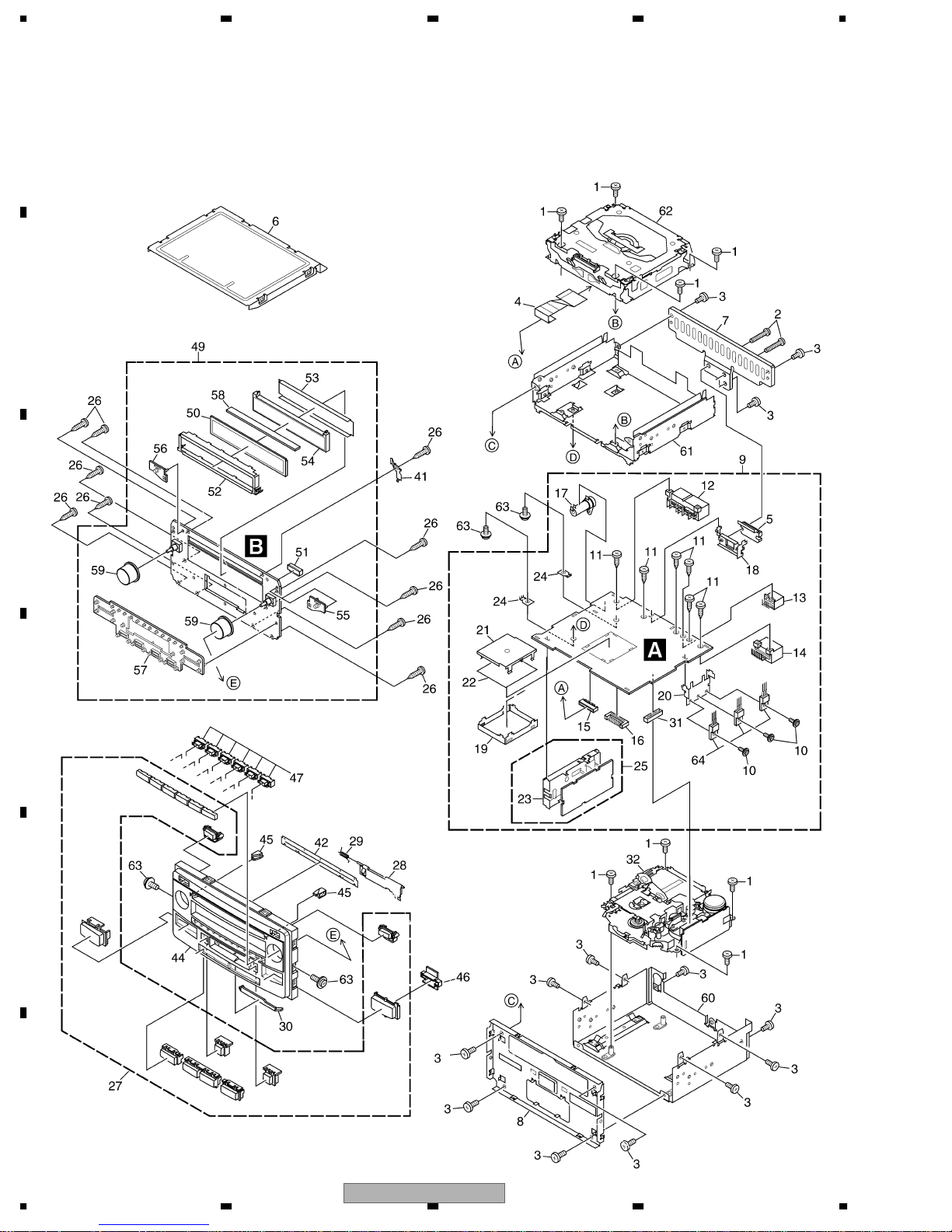
2. EXPLODED VIEWS AND PARTS LIST
OTES : • Parts marked by " * " are generally unavailable because they are not in our Master Spare Parts List.
A
• Screw adjacent to mark on the product are used for disassembly.
• For the applying amount of lobricants or glue, follow the instructions in this manual.
(In the case of no amount instructions,apply as you think it appropriate.)
"
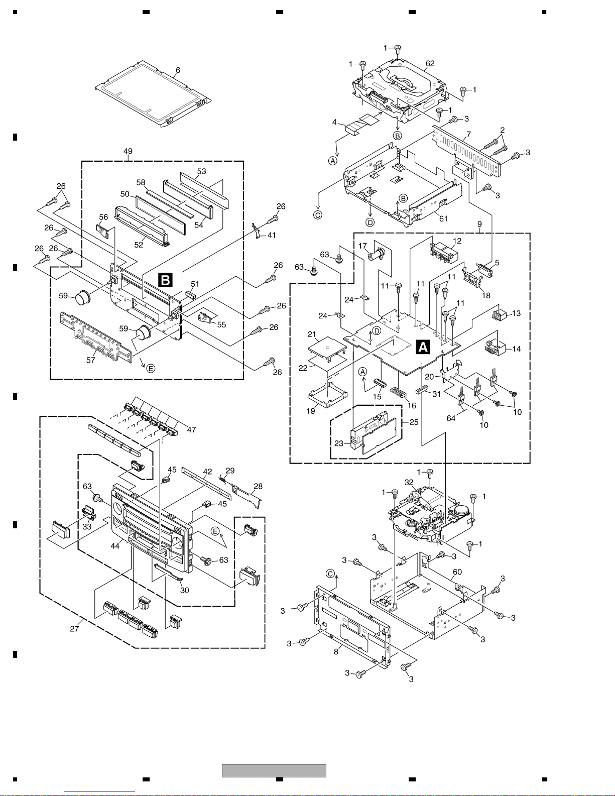
2.1 EXTERIOR(FH-M8047ZT/XN/ES,FH-M8047ZT/XIN/ES)
B
C
D
E
F
6
1234
FH-M8047ZT/XN/ES
5678
(1) EXTERIOR SECTION PARTS LIST(FH-M8047ZT/XN/ES,FH-M8047ZT/XIN/ES)
Mark No. Description Part No.
1 Screw BSZ26P060FTC
2 Screw BSZ26P140FTC
3 Screw BSZ30P080FTC
4 Connector CDE7172
5 IC(IC801) TDA7386
6 Case CNB2937
7 Heat Sink CNC9594
8 Frame CND2439
9 Main Unit CWM9213
10 Screw ASZ26P080FTC
11 Screw BPZ30P060FSN
12 Connector(CN471) CKM1222
13 Connector(CN473) CKM1350
14 Connector(CN472) CKM1351
15 Connector(CN601) CKS3837
16 Connector(CN479) CKS4573
17 86146-48030(CN501) CKX1057
18 Holder CNC9592
19 Shield CNC9595
20 Holder CND1080
21 Shield CND1118
22 Insulator CNM7823
23 Holder CNC8855
24 Terminal(CN474,475) VNF1084
25 FM/AM Tuner Unit CWE1557
26 Screw BPZ20P080FTC
27 Button Unit CXC4309
28 Door CAT2535
29 Spring CBH1371
30 Lighting Conductor CNV7941
Mark No. Description Part No.
31 Connector(CN631) CKS3568
32 Cassette Mechanism Module See Contrast table(2)
33 •••••
34-40 •••••
41 Earth Plate CND1990
42 Cover CNM7433
43 •••••
44 Grille See Contrast table(2)
45 Lighting Conductor CNV7939
46 Holder CNV7946
47 Holder CNV8015
48 •••••
49 Keyboard Unit CWM9216
50 LCD CAW1826
51 Connector(CN901) CKS4574
52 Holder CND1989
53 Sheet CNM8601
54 Lighting Conductor CNV7938
55 Rubber CNV7942
56 Rubber CNV7943
57 Rubber CNV7944
58 Connector CNV7947
59 Knob Unit CXC3300
60 Chassis Unit CXC2495
61 Chassis Unit CXC2856
62
63 Screw ISS26P055FTC
64 Transistor(Q431,441,851) 2SB1185
CD Mechanism Module S10MP3TOYOTA
A
B
C
CXK5681
D
(2) CONTRAST TABLE
FH-M8047ZT/XN/ES and FH-M8047ZT/XIN/ES are constructed the same except for the following:
Mark NO Description FH-M8047ZT/XN/ES FH-M8047ZT/XIN/ES
32
44 Grille CNS7980 CNS7728
Cassette Mechanism Module
56
EXK4282 EXK4280
FH-M8047ZT/XN/ES
7
E
F
8
7
1234
2.2 EXTERIOR(FH-M8147ZT/XN/ES,FH-M8147ZT/XIN/ES)
A
B
C
D
E
F
8
1234
FH-M8047ZT/XN/ES

5678
(1) EXTERIOR SECTION PARTS LIST(FH-M8147ZT/XN/ES,FH-M8147ZT/XIN/ES)
Mark No. Description Part No.
1 Screw BSZ26P060FTC
2 Screw BSZ26P140FTC
3 Screw BSZ30P080FTC
4 Connector CDE7172
5 IC(IC801) TDA7386
6 Case CNB2937
7 Heat Sink CNC9594
8 Frame CND2439
9 Main Unit CWM9213
10 Screw ASZ26P080FTC
11 Screw BPZ30P060FSN
12 Connector(CN471) CKM1222
13 Connector(CN473) CKM1350
14 Connector(CN472) CKM1351
15 Connector(CN601) CKS3837
16 Connector(CN479) CKS4573
17 86146-48030(CN501) CKX1057
18 Holder CNC9592
19 Shield CNC9595
20 Holder CND1080
21 Shield CND1118
22 Insulator CNM7823
23 Holder CNC8855
24 Terminal(CN474,475) VNF1084
25 FM/AM Tuner Unit CWE1557
26 Screw BPZ20P080FTC
27 Button Unit CXC4310
28 Door CAT2535
29 Spring CBH1371
30 Lighting Conductor CNV7941
Mark No. Description Part No.
31 Connector(CN631) CKS3568
32 Cassette Mechanism Module See Contrast table(2)
33 Holder CNV7946
34-40 •••••
41 Earth Plate CND1990
42 Cover CNM7433
43 •••••
44 Grille See Contrast table(2)
45 Lighting Conductor CNV7939
46 •••••
47 Holder CNV8015
48 •••••
49 Keyboard Unit CWM9364
50 LCD CAW1826
51 Connector(CN901) CKS4574
52 Holder CND1989
53 Sheet CNM8601
54 Lighting Conductor CNV7938
55 Rubber CNV7942
56 Rubber CNV7943
57 Rubber CNV7944
58 Connector CNV7947
59 Knob Unit CXC3300
60 Chassis Unit CXC2495
61 Chassis Unit CXC2856
62
63 Screw ISS26P055FTC
64 Transistor(Q431,441,851) 2SB1185
CD Mechanism Module S10MP3TOYOTA
A
B
C
CXK5681
D
(2) CONTRAST TABLE
FH-M8147ZT/XN/ES and FH-M8147ZT/XIN/ES are constructed the same except for the following:
Mark NO Description FH-M8147ZT/XN/ES FH-M8147ZT/XIN/ES
32
44
Cassette Mechanism Module
Grille
56
EXK4282 EXK4280
CNS7981 CNS7850
FH-M8047ZT/XN/ES
7
E
F
8
9
1234
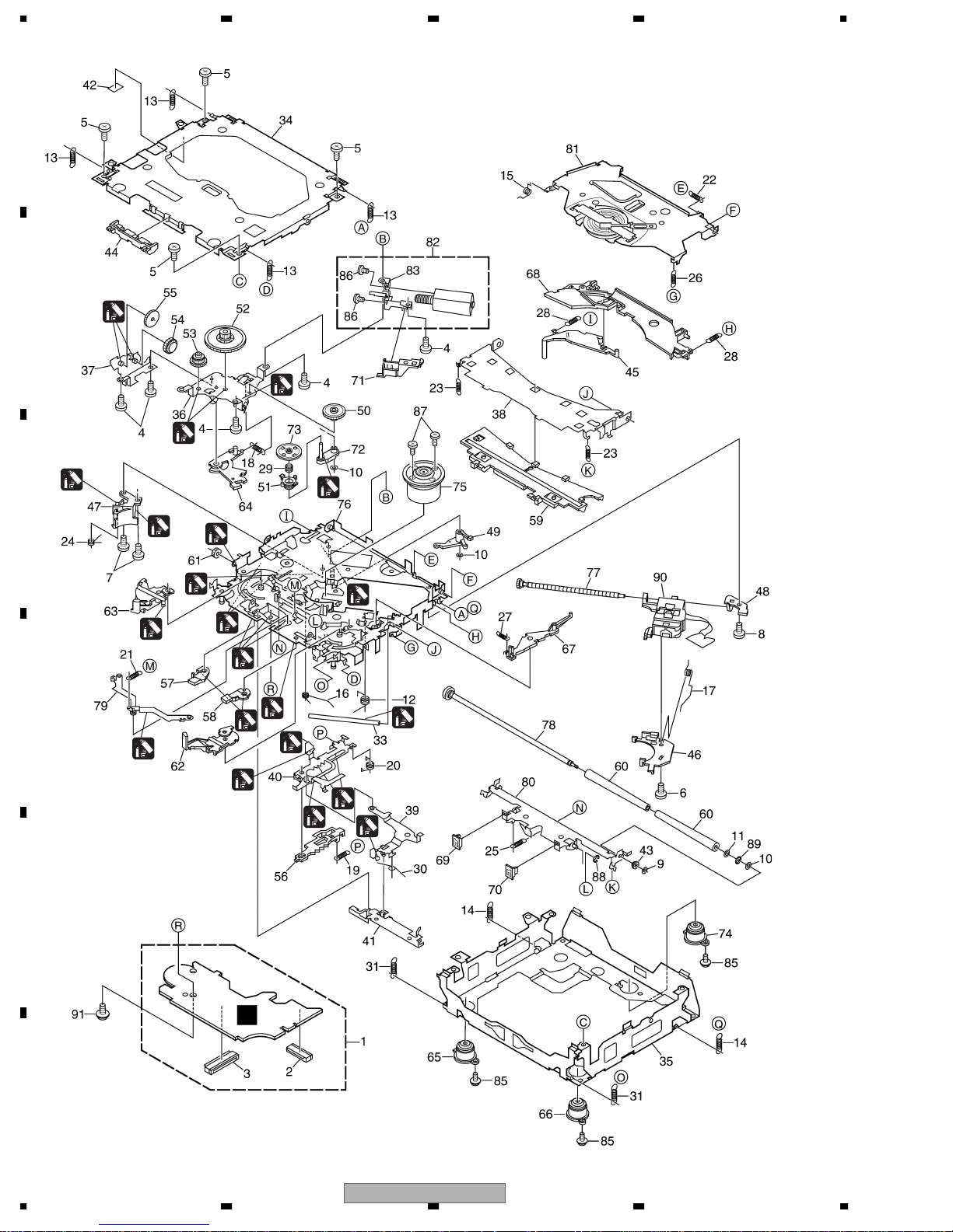
2.3 CD MECHANISM MODULE
A
B
1
1
1
2
1
C
2
1
2
2
D
2
1
1
1
1
2
1
3
1
1GEM1024
2GEM1045
3GEM1035
E
C
F
10
1234
1
1
1
FH-M8047ZT/XN/ES

5678
CD MECHANISM MODULE SECTION PARTS LIST
Mark No. Description Part No.
1 CD Core Unit(S10MP3) CWX3009
2 Connector(CN101) CKS4182
3 Connector(CN901) CKS4017
4 Screw BMZ20P035FTC
5 Screw BSZ20P040FTC
6 Screw(M2x4) CBA1362
7 Screw(M2x3) CBA1511
8 Screw(M2x3) CBA1527
9 Washer CBF1037
10 Washer CBF1038
11 Washer CBF1060
12 Spring CBH2390
13 Spring CBH2606
14 Spring CBH2607
15 Spring CBH2608
16 Spring CBH2609
17 Spring CBH2610
18 Spring CBH2611
19 Spring CBH2612
20 Spring CBH2613
21 Spring CBH2614
22 Spring CBH2615
23 Spring CBH2616
24 Spring CBH2617
25 Spring CBH2620
26 Spring CBH2621
27 Spring CBH2641
28 Spring CBH2642
29 Spring CBH2643
30 Spring CBH2659
31 Spring CBH2688
32 •••••
33 Shaft CLA4441
34 Frame CNC9962
35 Frame CNC9963
36 Bracket CNC9966
37 Bracket CNC9967
38 Arm CNC9968
39 Arm CNC9973
40 Lever CNC9983
41 Lever CNC9984
42 Sheet CNM8134
43 Collar CNV6906
44 Guide CNV6925
45 Arm CNV7198
Mark No. Description Part No.
50 Gear CNV7207
51 Gear CNV7208
52 Gear CNV7209
53 Gear CNV7210
54 Gear CNV7211
55 Gear CNV7212
56 Rack CNV7214
57 Arm CNV7215
58 Arm CNV7216
59 Guide CNV7217
60 Roller CNV7218
61 Gear CNV7219
62 Arm CNV7221
63 Arm CNV7220
64 Arm CNV7222
65 Damper CNV7634
66 Damper CNV7633
67 Arm CNV7341
68 Arm CNV7342
69 Guide CNV7360
70 Guide CNV7361
71 Holder CNV7437
72 Arm CNV7444
73 Gear CNV7595
74 Damper CNV7632
75 Motor Unit(M1) CXB6007
76 Chassis Unit CXB8728
77 Screw Unit CXB8729
78 Gear Unit CXB8731
79 Arm Unit CXB8732
80 Arm Unit CXC3278
81 Arm Unit CXB8852
82 Motor Unit(M2) CXB8933
83 Bracket CNC9985
84 •••••
85 Screw(M2x5) EBA1028
86 Screw JFZ20P020FTC
87 Screw JGZ17P022FTC
88 Washer YE15FTC
89 Washer YE20FTC
90 Pickup Unit(P10)(Service) CXX1664
91 Screw IMS26P030FTC
A
B
C
D
E
46 Rack CNV7199
47 Holder CNV7201
48 Holder CNV7202
49 Arm CNV7203
56
FH-M8047ZT/XN/ES
F
7
8
11
1234
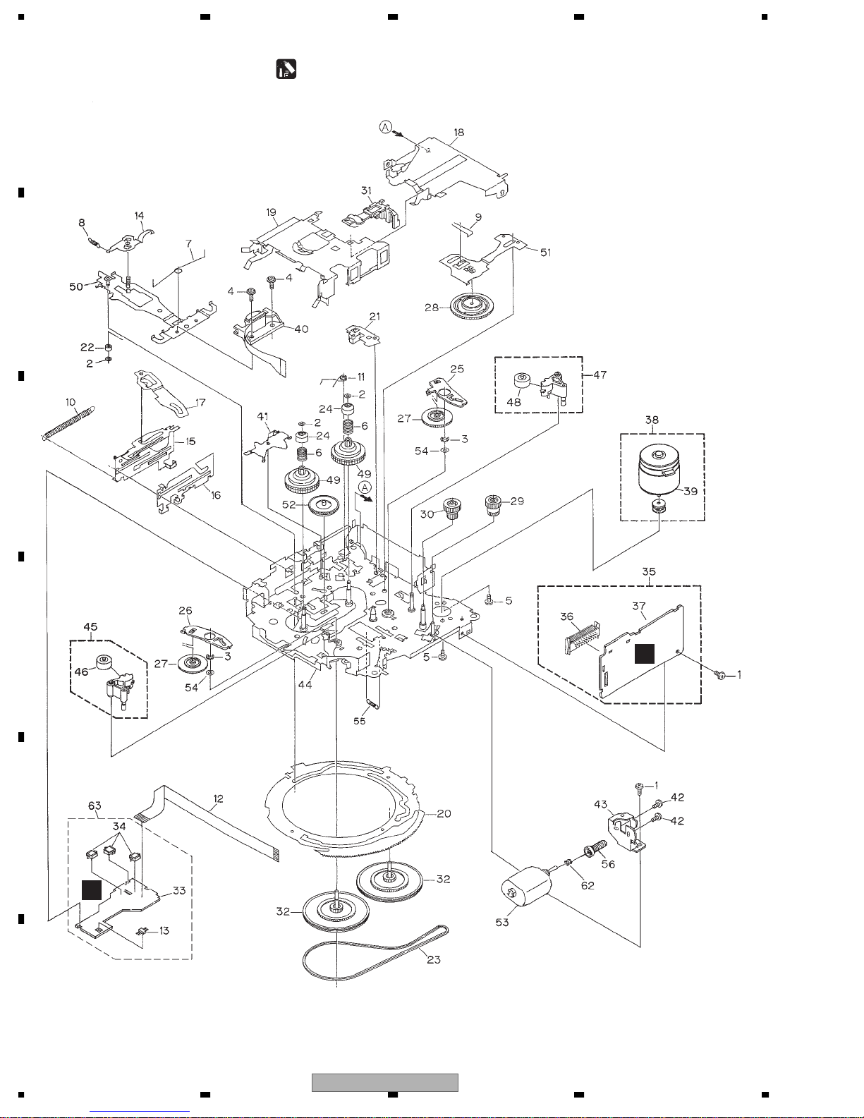
2.4 CASSETTE MECHANISM MODULE
For grease application, refer to the service manual for CX-1011 (CRT2406).
A
B
C
D
E
D
E
F
12
1234
FH-M8047ZT/XN/ES
5678
(1) CASSETTE MECHANISM MODULE SECTION PARTS LIST
Mark No. Description Part No.
1 Screw See Contrast table(2)
2 Washer CBF1037
3 Washer CBG1003
4 Screw EBA1028
5 Screw See Contrast table(2)
6 Spring EBH1653
7 Spring EBH1642
8 Spring EBH1641
9 Spring EBH1626
10 Spring EBH1627
11 Spring EBH1648
12 Cord EDD1024
13 Photo-reflector(Q101) EGN1004
14 Arm ENC1526
15 Lever ENC1544
16 Lever See Contrast table(2)
17 Arm ENC1532
18 Frame ENC1533
19 Holder ENC1534
20 Gear ENC1535
21 Arm ENC1550
22 Roller ENR1040
23 Belt ENT1027
24 Collar ENV1508
25 Arm ENV1539
26 Arm ENV1540
27 Gear ENV1569
28 Gear ENV1547
29 Gear ENV1560
30 Worm Wheel ENV1566
31 Lever ENV1551
32 Flywheel See Contrast table(2)
Mark No. Description Part No.
33 Gathering PCB ENX1073
34 Switch(S101,S102,S103) ESG1007
35 Deck Unit EWM1040
36 Plug(CN251) CKS3540
37 Gathering PCB ENX1074
38 Motor Unit(M1) EXA1618
39 Motor EXM1035
40 Head Assy(HD1) EXA1594
41 Arm ENC1537
42 Screw See Contrast table(2)
43 Bracket ENC1558
44 Chassis Unit See Contrast table(2)
45 Pinch Holder Unit EXA1608
46 Pinch Roller ENV1518
47 Pinch Holder Unit EXA1607
48 Pinch Roller ENV1518
49 Reel Unit EXA1625
50 Head Base Unit EXA1611
51 Lever Unit EXA1587
52 Gear Unit EXA1596
53 Motor Unit(M2) See Contrast table(2)
54 Washer HBF-179
55 Spring EBH1537
56 Worm Gear ENV1564
57 •••••
58 •••••
59 •••••
60 •••••
61 •••••
62 Spring EBH1545
63 Sensor Unit EWM1041
A
B
C
D
(2) CONTRAST TABLE
FH-M8047ZT/XN/ES, FH-M8147ZT/XN/ES, FH-M8047ZT/XIN/ES and FH-M8147ZT/XIN/ES are constructed the
same except for the following:
Mark NO Description
1 Screw BSZ20P040FTC BSZ20P040FMC
5 Screw EBA1031
16 Lever ENC1531 ENC1543
32 Flywheel ENV1607 ENV1554
42 Screw BMZ20P022FTC BMZ20P022FMC
44
53 Motor Unit(M2) EXA1657 EXA1627
Chassis Unit EXA1615 EXA1635
56
FH-M8047ZT/XN/ES
FH-M8147ZT/XN/ES
FH-M8047ZT/XN/ES
FH-M8047ZT/XIN/ES
FH-M8147ZT/XIN/ES
CBA1037
7
E
F
8
13
d
M
N
D
K
S
1234
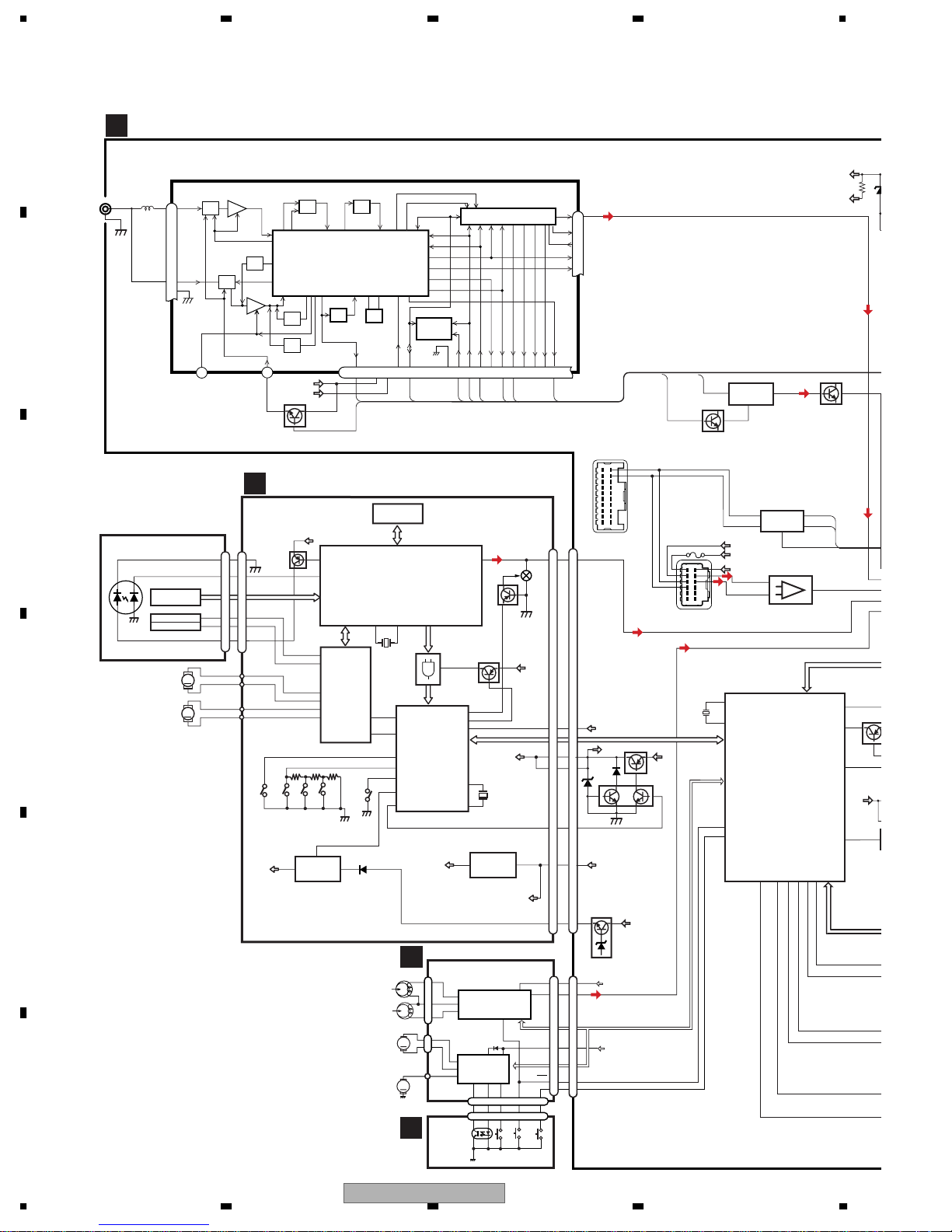
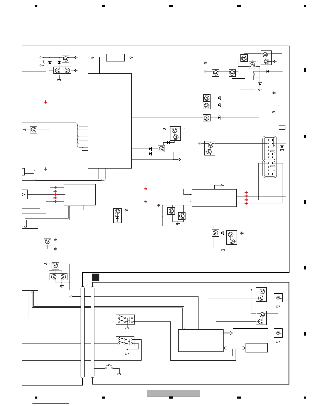
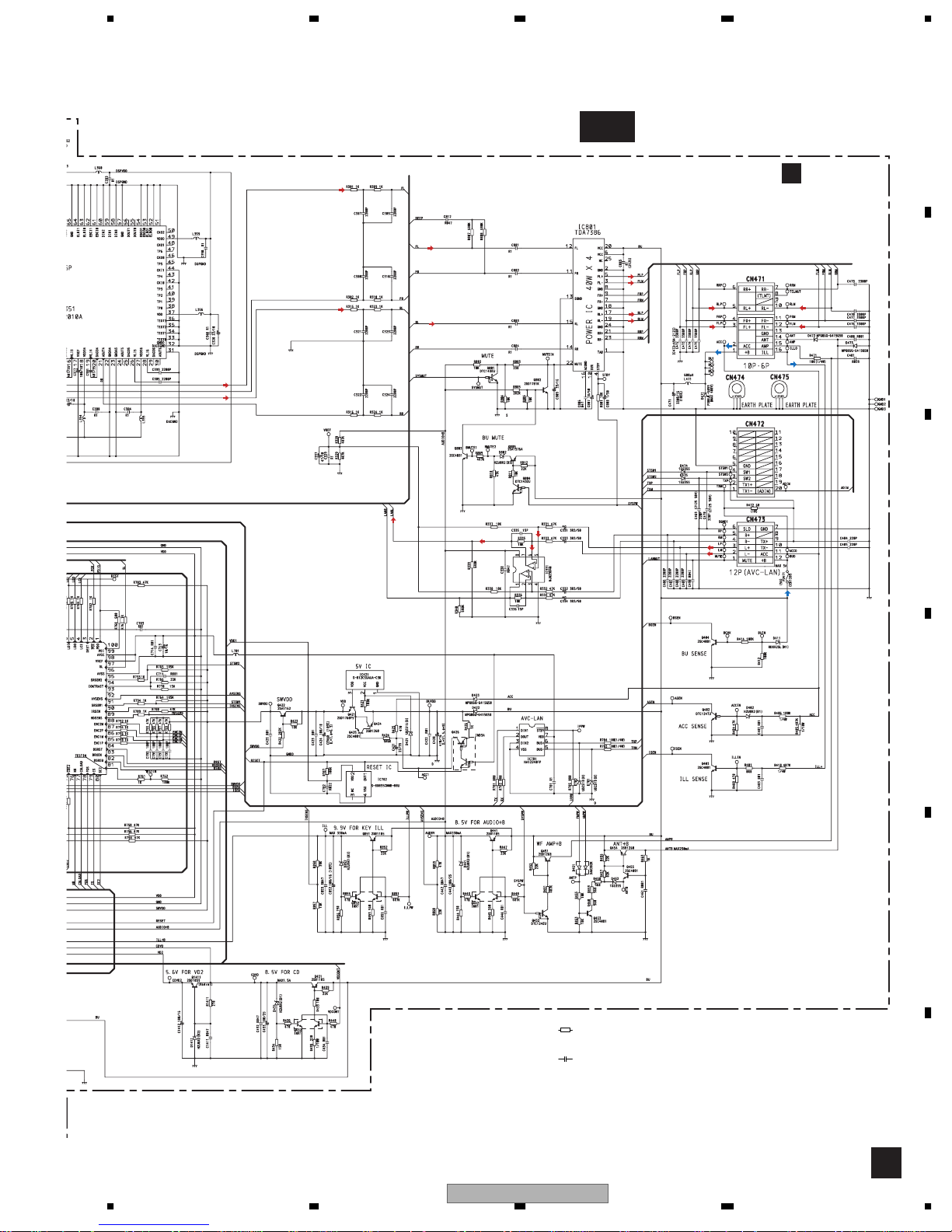
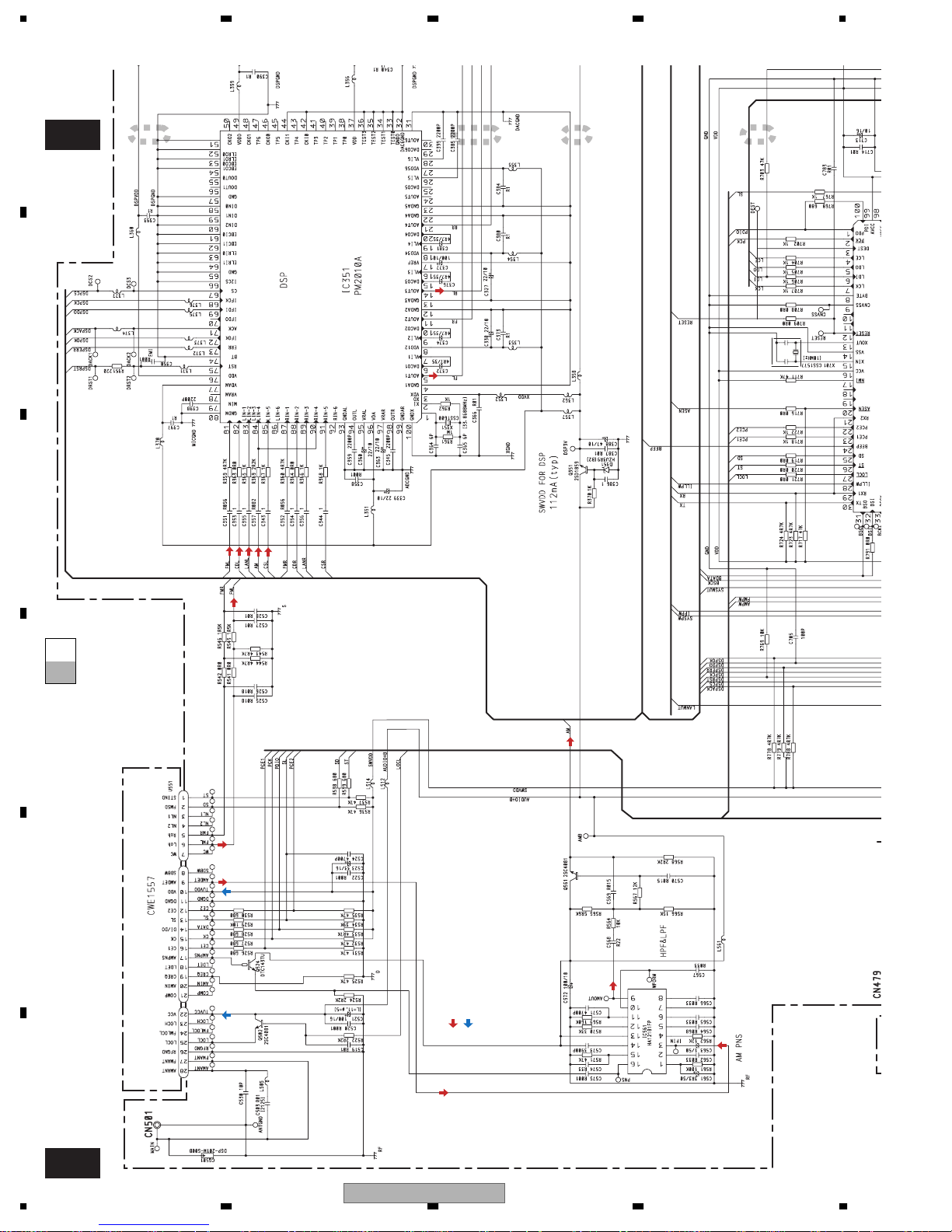
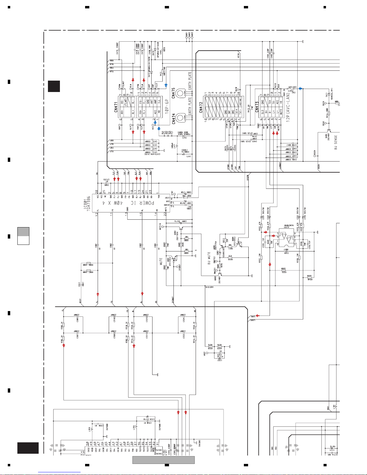
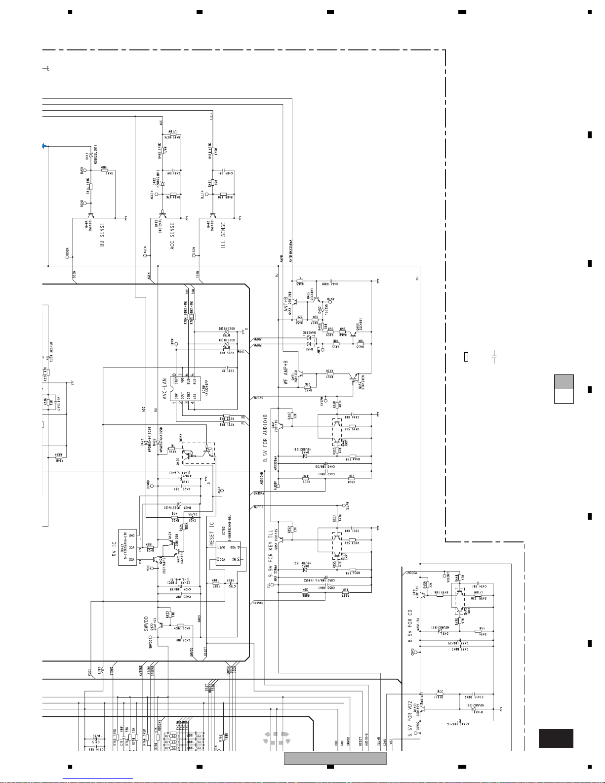
3. BLOCK DIAGRAM AND SCHEMATIC DIAGRAM
3.1 BLOCK DIAGRAM
A
MAIN UNIT
A
FM/AM TUNER UNIT
ANTENNA
JACK
1
2
AMANT
28
ATT
FMANT
27
26
RFGND
ATT
CN501
B
LOCH
23
C
D
PICKUP UNIT
(SERVICE)(P10)
LASER
DIODE
MONITOR
DIODE
LOAD/
HOLOGRAM
FOCUS ACT.
TRACKING ACT.
SPINDLE
MOTOR
CARRIAGE
MOTOR
UNIT
LD-
MD
FO+
TO+
LD+
M
M
15
14
AMRF
5
1
4
ANT ADJ
FMRF
C
CN101
15
5
FOP
1
TOP
4
14
V3R3D
FM/AM 1ST IF 10.7MHz
T51 Q51 CF51
CF52 CF53
IC1
MIXER, IF AMP, DET.
CF202
RF ADJ
AUDIO+B
SWVDD
Q502
AM 2ND IF
450kHz
WC
10.25MHz
AMPNS
177
IMG ADJ
LOCL
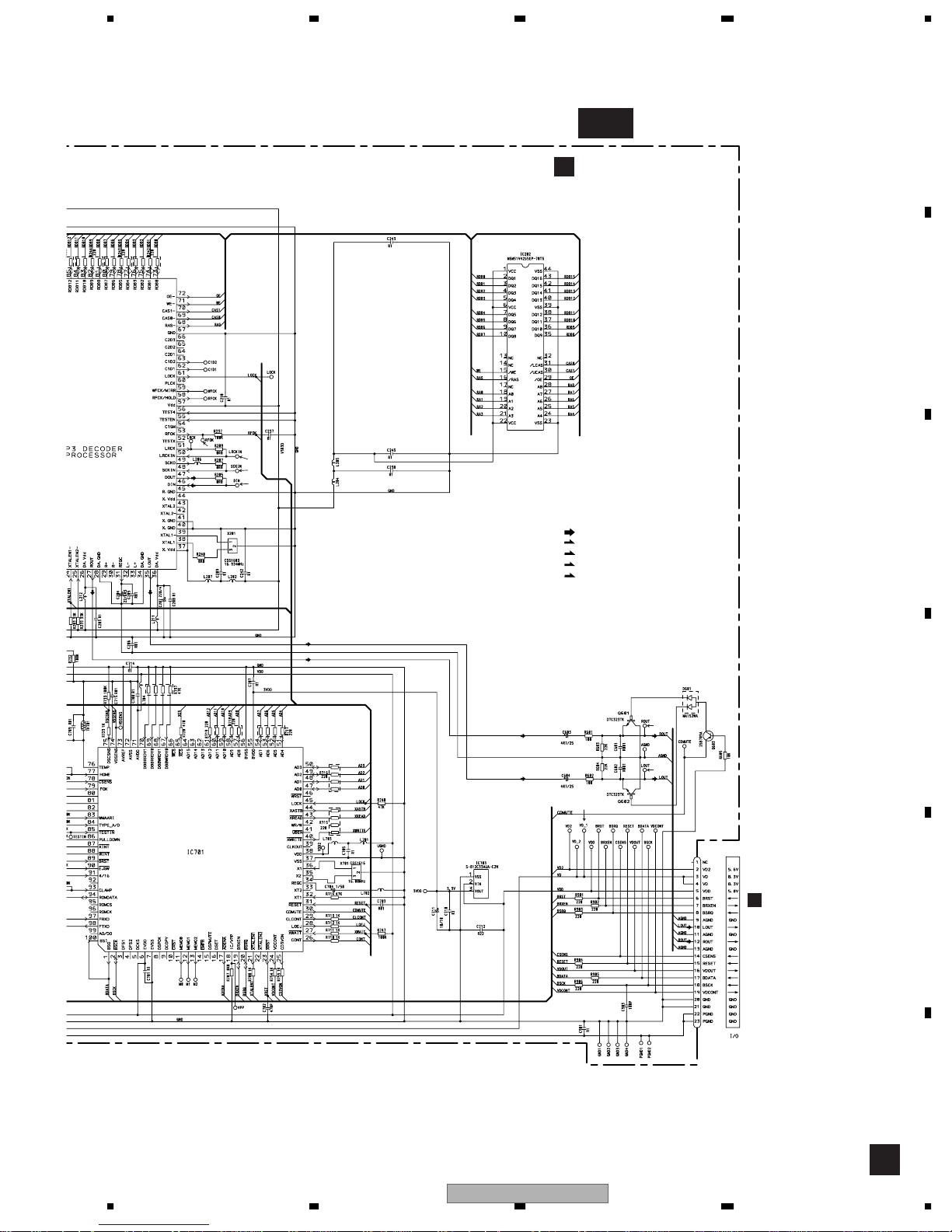
CD CORE UNIT(S10MP3)
C
V3R3D
142
12EJ
LD
141
PD
RF-AMP,CD DECODER,
DIGITAL SERVO / DATA PROCESSOR
TD/FD
SD/MD
12
CD
FOP
13
DRIVER
TOP
IC 301
BA5996FM
16
SOP
15
SOM
18
LCOP
17
LCOM
LOEJ
CONT
DISC
8EJ
SENSE
SENSE
1
2
IC 203
4
BA033SFP
CLAMP
SENSE
Q101
AC,BD
F,E
SENSE
+3.3V REGULATOR
E
MPXREF 41kHz
AMDET
IC 2 FM MPX
X901
VCC
222510 14 12 15 16 8 13 2 3 4
LOCL
UPD63760GJ
MP3 DECODER,
X201
22
9
HOME
IC 3
EEPROM
VDD
FMLOCL
CREQ
DI/DO
19
PDIO
DRAM
MSM51V4265EP-70TS
IC 201
3938
WINT,
WAIT,
RFOK
XWINT,
TC74VHCT08AFT
XWAIT,
FOK
28
LOEJ
26
CONT
CD CONTROLLER
93
CLAMP
IC 701
75
DSCSNS
PE5427A
77
HOME
25
CD3VON
24
VDCONT
DGND
11
IC 202
14 VCC
IC 702
CDMUTE
ADENA
reset
CE2CKCE1
LOUT
33
17
31
36
X1
35
X2
SDBWSLFMSD
35
MUTE
Q603
Q701
BRST,BRXEN,BSRQ
BDATA,BSCK
X701
+3.3V REGULATOR
1
VD2
3VDD
IC 703
S-812C33AUA-C2N
L ch
FM L
6
R ch
5
AMIN
20
COMP
21
LDET
18
STIND
AMDET
NL1
CN901
LOUT
Q602
NL2
924
1
CN472
TX1-
TX1+
CN601
10
10
TXTX+
AMPNS
AM NOISE CANCELER
3
IC 561
AMDET
HA12181FP
Q524
16
AVC-LAN DRIVER
BUS-
5
6
BUS+
HA12240FP
ACC
BU
LANMUT
NJM2904M
BUS-L
6
5
BUS+L
CN473
VDD
13
XOUT
X701
15
15
15
VD
VD
RESET
BRST,BRXEN,BSRQ
Q431
VD
3
3
4
4
Q432
BDATA,BSCK
BU
XIN
IC 701(2/2)
PD5949B
SYSTEM CONTROL
VDCONT
4,5
VDD
19
19
VD REGULATOR
5
5
VDD
VD2
Q1411
2
2
VD
68
mtl
77
CSLOAD
cdej
63
74
9
IC 781
IC 331
POWER
88 87
8
AUDIO+B
AM
TX
1
RX
2
IPPW
7
7
dsprst,dsperr,IFOK,
SYSMUTE
LANMUTE
SYSPW
ILLPWM
ENC1M
ENC1P
ENC2M
ENC2P
86 85
1/2VCC
Q561
F
LA
C
C
42
Q701
46
49
BU
28
LCE,LC
F
14
1234
DECK UNIT
D
CN252
L-ch
REV
L-ch
SUB
MAIN
1
39
32
5
33
4
CN254
E
2
1
CN255
CN253
CN256
MECHANISM
M2
M
M1
M
FWD
MOTOR
MOTOR
SENSOR UNIT
FH-M8047ZT/XN/ES
DOLBY B NR
HA12228F
DRIVER
18
5
2
IC351
1
PA2020A
8
3
3
EGN1
REEL
SENSE
CN251
15
10
MODE
6
19
19
LOAD
4
4
S3
S2
LOAD
70µs
IC251
7
15 6
15 6
CN631
4
4
Lch
3
B.U
20
MTL
8
11
S1
AUDIO+B
Lch
3
20
BU
8
11
ENC2P
5678
A
R
IVER
P
IPPW
4M
1
2
7
AUDIO+B
Q561
TX
RX
7
1/2VCC
FM L
LANL
CD L
CS L
Q442
AM
84
81
83
82
85
Q441
BU
RESET
SYSPW
27
25
97
23
PCE1
2
pck
22
ce@
PDIO
1
100
DSP/
ELECTRONIC VOLUME/
SOURCE SELECTOR
LIN-4
LIN-1
IC 351
LIN-3
PM2010A
LIN-2
LIN-5
VDD
3,8,18,27,37,49,76,77,96
1
S-80835CNNB-B8U
12
reset
SYSTEM CONTROL
IC 701(1/2)
PD5949B
locl
SD
SL
PCE1
pck
PCE2
PDO
PDI
TX
RX1
IPPW
30 29 47
TX
RX
5
FL
14
RL
DSP VDD (3.3V)REGULATOR
RESET
IC 782
Q351
2
swvdd
bsen
asen
isen
FMPW
AMPW
SYSPW
VDD
65
73
20
58
44
45
49
AUDIO+B
AUDIO+B
Q453
VDD
SWVDD
Q422
Q421
Q425
Q426
Q424
32
BU
VDD
IC 421
Q404
B SENSE
A SENSE
Q402
ANT +B
Q454
BU
Q455
BU
SYSPW
Q403
WF AMP+B
Q451
Q452
I SENSE
S-812C56AUA-C3K
BU
ACC
ILL
BU
B
ACC
LPF
CN471
ILL
AMP
ANT
FL-
RL-
ACC
+B
FL+
RL+
C
BU
6,20
Q801
MUTE
Q802
12
FLIN
15
RLIN
22
VCC
POWER AMP
IC 801
TDA7386
STBYMUTE
4
3
FL-
5
FL+
19
RL-
17
RL+
SYSPW
dsprst,dsperr,IFOK,dspack,IFDI,IFDO,IFCLK,dspcs
42
2)
B
86 85
SYSMUTE
LANMUTE
TROL
ENC1M
ILLPWM
ENC1P
SYSPW
Q701
46
49
BU
28
LCE,LCK,LDO,LDI
SWVDD
LANMUT
Q851
Q852
SWVDD
CN479
SWILL+B
SWVDD
ENC1P
ENC1M
ENC2P
ENC2M
POWER
cdej
BU MUTE
Q803
Q805
BU
SYSPW
Q804
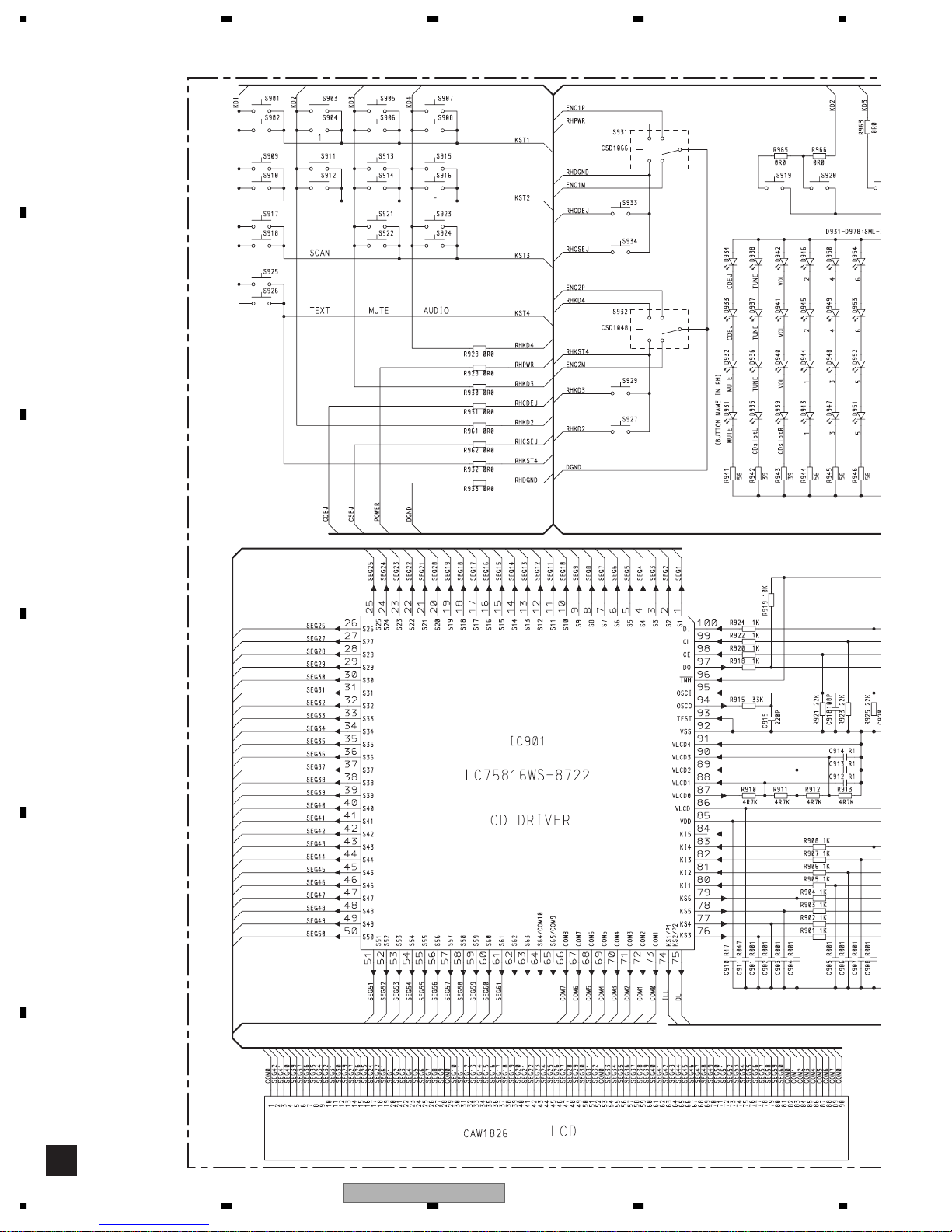
KEYBOARD UNIT
B
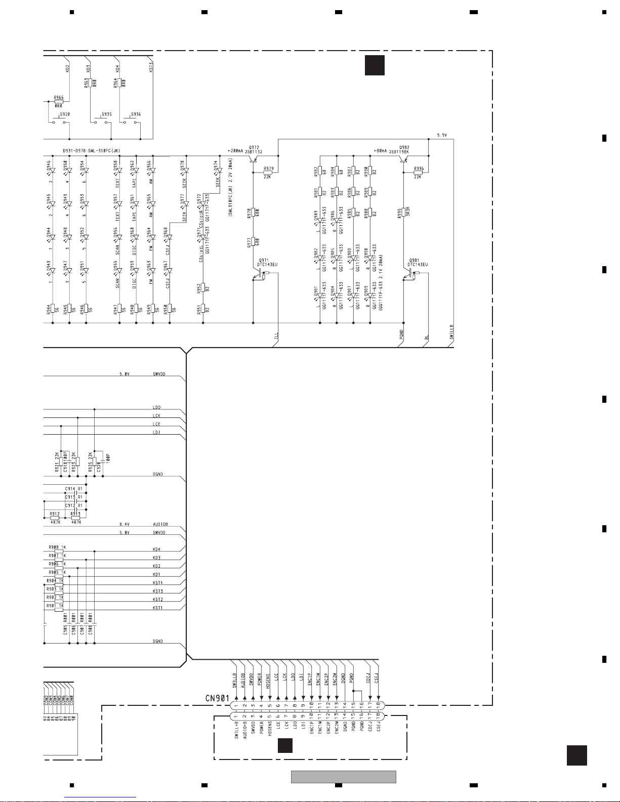
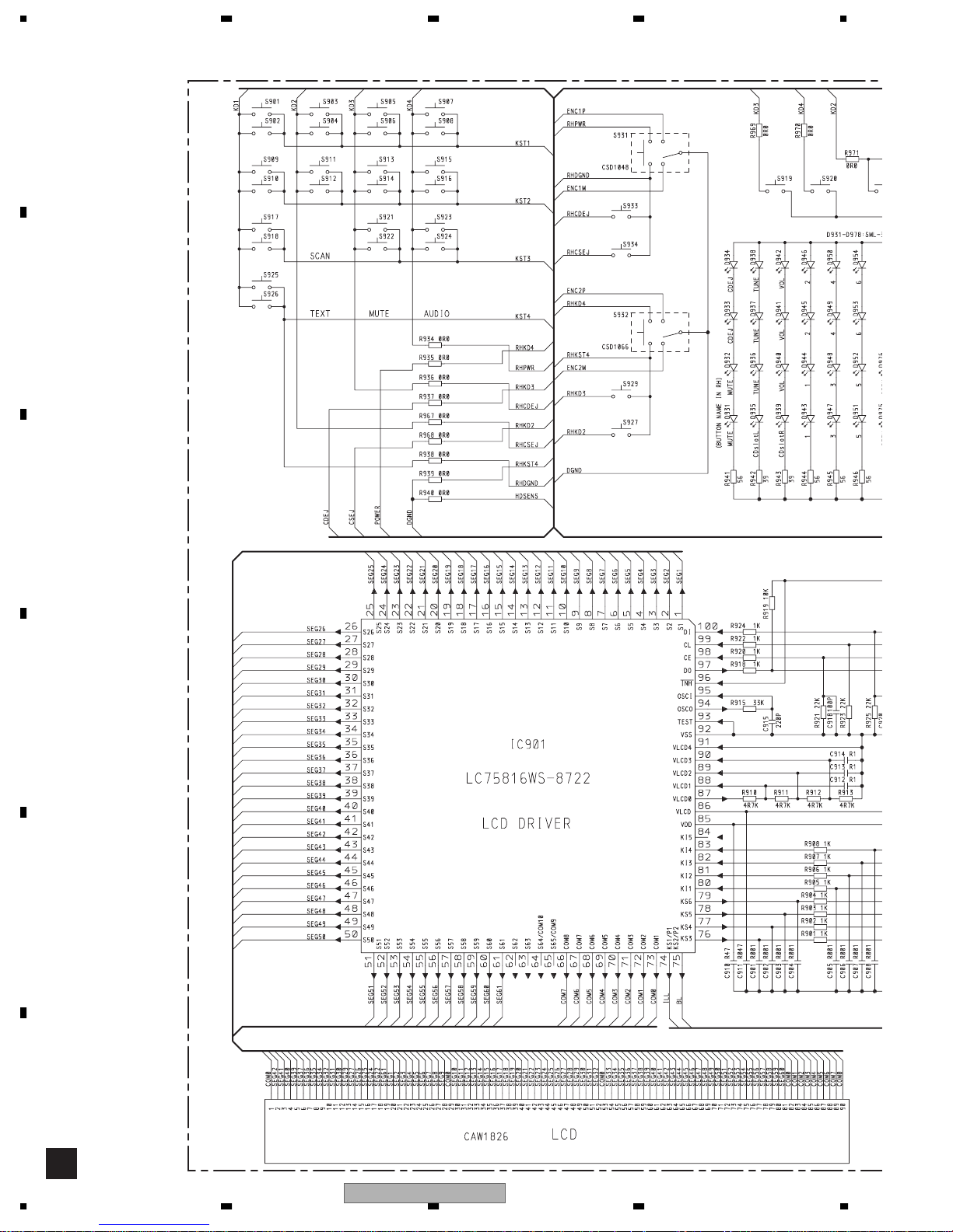
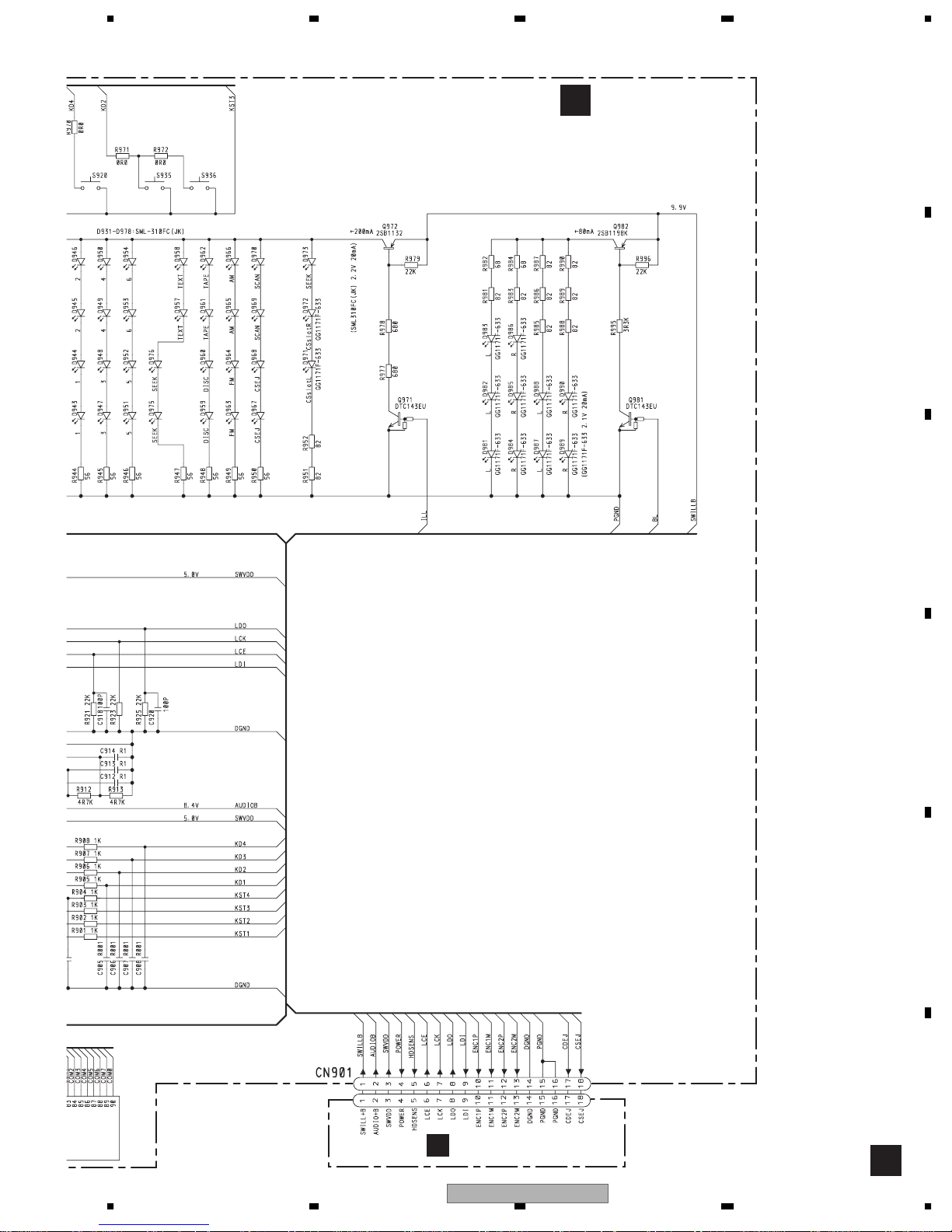
CN901
SWILLB
1
1
SWVD
3
3
LCE,LCK,LDO,LDI
TUNE•FILE(FH-M8047ZT/XN/ES,FH-M8047ZT/XIN/ES)
PWR•VOL(FH-M8147ZT/XN/ES,FH-M8147ZT/XIN/ES)
S932
S931
KD4
KST4
KEY CONTROLLER
LC75816WS-8722
POWER
cdej
ENC1P
ENC1M
PWR•VOL(FH-M8047ZT/XN/ES,FH-M8047ZT/XIN/ES)
TUNE•FILE(FH-M8147ZT/XN/ES,FH-M8147ZT/XIN/ES)
ENC2P
ENC2M
EJECT
S933
10
10
11
11
12
12
13
13
4
4
17
17
85
VDD
LCD DRIVER/
IC 901
ILL
74
KS1/P1
BL
75
KS2/P2
KEY DATA
ILLUMINATION
KD4
KST4
Q971
Q981
LCD
KEY MATRIX
Q972
Q982
LCD
BACKLIGHT
D
E
F
56
FH-M8047ZT/XN/ES
7
8
15
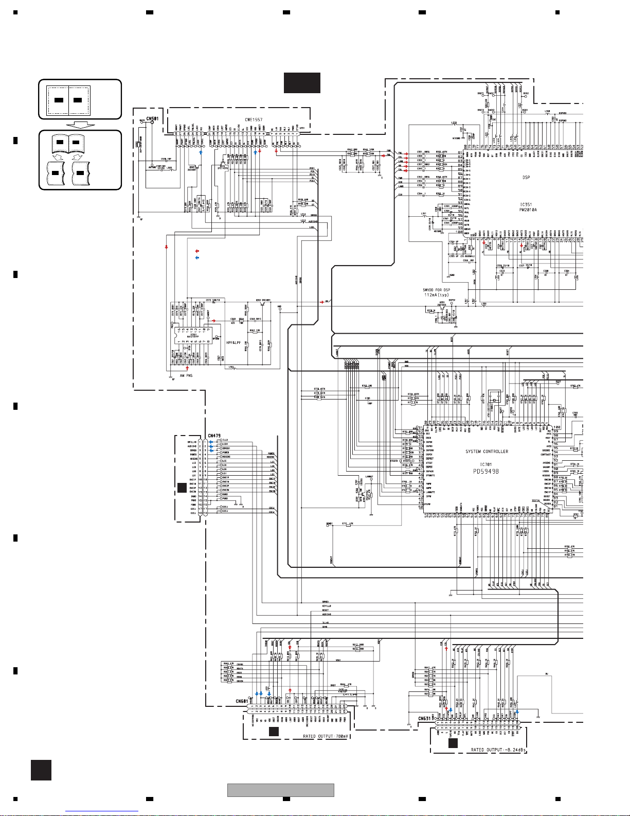
1234
3.2 OVERALL CONNECTION DIAGRAM(GUIDE PAGE)
Note: When ordering service parts, be sure to refer to " EXPLODED VIEWS AND PARTS LIST" or
"ELECTRICAL PARTS LIST".
A
A-a
TAPE:-11dBs
FM:-27dBs
AM:-28dBs
P
FM:-24dBs
CD: 0dBs
A-a A-b
A-a
A-b
Large size
SCH diagram
Guide page
FM/AM TUNER UNIT
P
A-b
Detailed page
A-a
B
: SIGNAL LINE
P
: POWER SUPPLY LINE
AM:-12dBs
C
P
P
P
D
CN901
B
E
CD:0dBs
TAPE:-11dBs
P
P
P
P
CN901
F
C
CN251
D
P
A
16
1234
FH-M8047ZT/XN/ES
5678
A
A-b
MAIN UNIT
A
SPOUT BAL
TAPE:+21dBs
FM:+14dBs
AM:+17dBs
CD:+27dBs
B
P
P
P
C
>
P
D
E
56
NOTE :
Symbol indicates a resistor.
No differentiation is made between chip resistors and
discrete resistors.
Symbol indicates a capacitor.
No differentiation is made between chip capacitors and
discrete capacitors.
The > mark found on some component parts indicates
the importance of the safety factor of the part.
Therefore, when replacing, be sure to use parts of
identical designation.
FH-M8047ZT/XN/ES
Decimal points for resistor
and capacitor fixed values
are expressed as :
←
2.2 2R2
←
0.022 R022
F
A
7
8
17
A
B
A-b
1234
1
2
3
4
C
A-b
A-a
A-a
CD: 0dBs
FM:-27dBs
AM:-28dBs
TAPE:-11dBs
D
FM:-24dBs
P
E
FM/AM TUNER UNIT
AM:-12dBs
P
F
A-a
18
1234
: SIGNAL LINE
: POWER SUPPLY LINE
P
FH-M8047ZT/XN/ES

5678
A
5
A-b
TAPE:-11dBs
P
B
CN251
P
D
A-b
A-a
A-a
C
D
P
P
P
B
CN901
56
FH-M8047ZT/XN/ES
CD:0dBs
7
CN901
P
P
P
C
E
F
A-a
8
19
1234
A
MAIN UNIT
A
P
FM:+14dBs
CD:+27dBs
AM:+17dBs
SPOUT BAL
B
TAPE:+21dBs
P
P
>
P
C
A-b
A-a
D
E
F
A-b
20
1
1234
2
FH-M8047ZT/XN/ES
3
4
5678
A
←
←
Decimal points for resistor
and capacitor fixed values
are expressed as :
2.2 2R2
P
0.022 R022
B
C
Symbol indicates a resistor.
No differentiation is made between chip resistors and
discrete resistors.
Symbol indicates a capacitor.
No differentiation is made between chip capacitors and
discrete capacitors.
The > mark found on some component parts indicates
the importance of the safety factor of the part.
Therefore, when replacing, be sure to use parts of
NOTE :
identical designation.
A-b
A-a
D
E
56
5
FH-M8047ZT/XN/ES
F
A-b
7
8
21
1234
W
3.3 KEYBOARD UNIT(FH-M8047ZT/XN/ES,FH-M8047ZT/XIN/ES)
A
DISC
1
4
6
PWR•VOL
TAPE
B
AM
2
3
DOWNFM
UP
5
CD EJECT
TAPE EJECT
TUNE•FILE
MUTE
TEXT
SCAN
SCAN DO
C
D
E
F
B
22
1234
FH-M8047ZT/XN/ES
SCAN UPDOWN
5678
KEYBOARD UNIT
B
A
B
C
D
E
56
CN479
A
FH-M8047ZT/XN/ES
F
B
7
8
23
1234
A
3.4 KEYBOARD UNIT(FH-M8147ZT/XN/ES,FH-M8147ZT/XIN/ES)
A
UP
6
5
TUNE•FILE
MUTE
TEXT
PWR•VOL
CD EJECT
TAPE EJECT
UPDOWN
SC
AM
FM
TAPE
B
DISC
1
2
4
3
DOWN
C
D
E
F
B
24
1234
FH-M8047ZT/XN/ES
5678
KEYBOARD UNIT
B
SCANSCANUP
A
B
C
D
E
56
CN479
A
FH-M8047ZT/XN/ES
F
B
7
8
25
1234
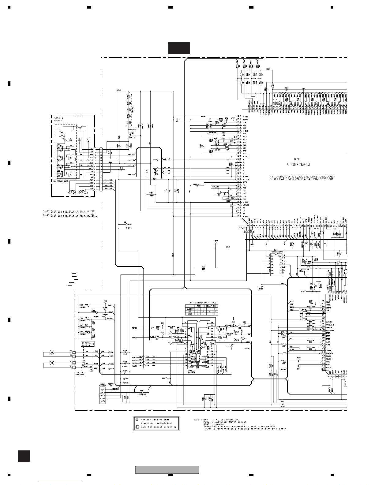
3.5 CD MECHANISM MODULE(GUIDE PAGE)
A
C-a
PICKUP UNIT
(P10)(SERVICE)
B
S
C
T
F
S
CTF
CN101
F
T
T
F
T
T
F
F
F
T
T
F
F
F
T
T
#
F
F
T
T
0
!
C
SWITCHES:
CD CORE UNIT(S10MP3)
S901 : HOME SWITCH.....ON-OFF
S902 : CLAMP SWITCH....ON-OFF
S903 : DSCSNS SWITCH....ON-OFF
D
S904 : 12EJ SWITCH....ON-OFF
S905 : 8EJ SWITCH....ON-OFF
The underlined indicates the original switch position.
5/3.3
1
SPINDLE MOTOR
M1 CXB6007
E
LOADING/CARRIAGE
MOTOR
M2 CXB8933
S
S
C
C
SW 3.3 REGULATOR
F
C
26
1234
T
7
F
8
F
F
T
T
FH-M8047ZT/XN/ES
CD DRIVER
@
S
5
C
6
3
2
CCS
S
R735
47K
5678
A
C-b
CD CORE UNIT(S10MP3)
C
D-RAM
B
9
$
^
%
PE5427A
MICRO COMPUTER
3.3 REGULATOR
SIGNAL LINE
F
FOCUS SERVO LINE
T
TRACKING SERVO LINE
C
CARRIAGE SERVO LINE
S
SPINDLE SERVO LINE
4
C
*
&
CN901
A
CN601
D
E
56
FH-M8047ZT/XN/ES
F
C
7
8
27
 Loading...