

Pioneer DVR-LX70 User Manual
Thank you for buying this Pioneer product.
Please read through these operating instructions so you will know how to operate your model properly.
After you have finished reading the instructions, put them away in a safe place for future reference.
IMPORTANT
CAUTION
RISK OF ELECTRIC SHOCK
DO NOT OPEN
The lightning flash with arrowhead symbol,
within an equilateral triangle, is intended to
alert the user to the presence of uninsulated
"dangerous voltage" within the product's
enclosure that may be of sufficient
magnitude to constitute a risk of electric
shock to persons.
CAUTION:
TO PREVENT THE RISK OF ELECTRIC
SHOCK, DO NOT REMOVE COVER (OR
BACK). NO USER-SERVICEABLE PARTS
INSIDE. REFER SERVICING TO QUALIFIED
SERVICE PERSONNEL.
The exclamation point within an equilateral
triangle is intended to alert the user to the
presence of important operating and
maintenance (servicing) instructions in the
literature accompanying the appliance.
D3-4-2-1-1_En-A
WARNING
This equipment is not waterproof. To prevent a fire
or shock hazard, do not place any container filled
with liquid near this equipment (such as a vase or
flower pot) or expose it to dripping, splashing, rain
or moisture.
D3-4-2-1-3_B_En
CAUTION
This product is a class 1 laser product, but this product
contains a laser diode higher than Class 1.
To ensure continued safety, do not remove any covers or
attempt to gain access to the rear of the product.
Refer all servicing to qualified personnel.
The following caution label appears on your unit.
Location: inside of the unit
CLASS 3B VISIBLE AND INVISIBLE LASER RADIATION WHEN OPEN, AVOID EXPOSURE TO THE BEAM.
CAUTION
RADIATIONS LASER VISIBLES ET INVISIBLES DE CLASSE 3B QUAND OUVERT. ÉV ITEZ TOUT EXPOSITION AU FAISCEAU.
ATTENTION
KLASSE 3B SYNLIG OG USYNLIG LASERSTRÅLING VED ÅBNING. UNDGÅ UDSÆTTELSE FOR STRÅLING.
ADVARSEL
KLASS 3B SYNLIG OCH OSYNLIG LASERSTRÅLNING NÄ R DENNA DEL ÄR ÖPPNAD. UNDVIK AT T UT SÄTTA DIG FÖR STRÅLEN.
VARNING
BEI GEÖFFNETER ABDECKUNG IST SICHTB ARE UND UN SICH TBARE LASERSTRAHLUNG DER KLASSE 3B IM GERÄTEINNEREN VORHAND EN.
VORSICHT
NICHT DEM LASERSTRAHL AUSSETZEN!
CUANDO SE ABRE HAY RADIACIÓN LÁSER DE CLASE 3B VISIBLE E INV IS IB LE . E VI T E LA EX PO SIC IÓN A LOS RAYO S LÁSER.
PRECAUCIÓN
AVATTAESSA OLET ALTTIINA NÄKYVÄLLE JA NÄKYMÄTTÖMÄLLE LUOKAN 3B LASERSÄTEILYLLE. ÄLÄ KATSO SÄTEESEEN.
VARO!
WARNING
To prevent a fire hazard, do not place any naked
flame sources (such as a lighted candle) on the
equipment.
D3-4-2-1-7a_A_En
WARNING
Before plugging in for the first time, read the following
section carefully.
The voltage of the available power supply differs
according to country or region. Be sure that the
power supply voltage of the area where this unit
will be used meets the required voltage (e.g., 230 V
or 120 V) written on the rear panel.
VRW2262 - A
D3-4-2-1-4_A_En
D3-4-2-1-8_B_En
Operating Environment
T
Operating environment temperature and humidity:
+5 ºC to +35 ºC (+41 ºF to +95 ºF); less than 85 %RH
(cooling vents not blocked)
Do not install this unit in a poorly ventilated area, or in
locations exposed to high humidity or direct sunlight (or
strong artificial light)
D3-4-2-1-7c_A_En
VENTILATION CAUTION
When installing this unit, make sure to leave space
around the unit for ventilation to improve heat
radiation (at least 10 cm at top, 10 cm at rear, and
10 cm at each side).
WARNING
Slots and openings in the cabinet are provided for
ventilation to ensure reliable operation of the
product, and to protect it from overheating. To
prevent fire hazard, the openings should never be
blocked or covered with items (such as newspapers,
table-cloths, curtains) or by operating the
equipment on thick carpet or a bed.
D3-4-2-1-7b_A_En
CAUTION
The STANDBY/ON switch on this unit will not
completely shut off all power from the AC outlet.
Since the power cord serves as the main disconnect
device for the unit, you will need to unplug it from
the AC outlet to shut down all power. Therefore,
make sure the unit has been installed so that the
power cord can be easily unplugged from the AC
outlet in case of an accident. To avoid fire hazard,
the power cord should also be unplugged from the
AC outlet when left unused for a long period of time
(for example, when on vacation).
D3-4-2-2-2a_A_En
This product is for general household purposes. Any
failure due to use for other than household purposes
(such as long-term use for business purposes in a
restaurant or use in a car or ship) and which
requires repair will be charged for even during the
warranty period.
K041_En
If the AC plug of this unit does not match the AC
outlet you want to use, the plug must be removed
and appropriate one fitted. Replacement and
mounting of an AC plug on the power supply cord of
this unit should be performed only by qualified
service personnel. If connected to an AC outlet, the
cut-off plug can cause severe electrical shock. Make
sure it is properly disposed of after removal.
The equipment should be disconnected by removing
the mains plug from the wall socket when left
unused for a long period of time (for example, when
on vacation).
D3-4-2-2-1a_A_En
For Taiwan exclusively
aiwanese two pin flat-bladed plug
POWER-CORD CAUTION
Handle the power cord by the plug. Do not pull out the
plug by tugging the cord and never touch the power
cord when your hands are wet as this could cause a
short circuit or electric shock. Do not place the unit, a
piece of furniture, etc., on the power cord, or pinch the
cord. Never make a knot in the cord or tie it with other
cords. The power cords should be routed such that they
are not likely to be stepped on. A damaged power cord
can cause a fire or give you an electrical shock. Check
the power cord once in a while. When you find it
damaged, ask your nearest PIONEER authorized
service center or your dealer for a replacement.
S002_En

01
Contents
01 Before you start
What’s in the box . . . . . . . . . . . . . . . . . . . 6
Putting the batteries in the remote
control. . . . . . . . . . . . . . . . . . . . . . . . . . . . 6
Using the remote control. . . . . . . . . . . . . . 6
Disc/content format playback
compatibility . . . . . . . . . . . . . . . . . . . . . . . 7
About the internal hard disk drive . . . . . . 12
Symbols used in this manual . . . . . . . . . 13
02 Connections
Rear panel connections. . . . . . . . . . . . . . 14
Front panel connections . . . . . . . . . . . . . 15
Easy connections . . . . . . . . . . . . . . . . . . 16
Using other types of video output . . . . . . 17
Connecting to a cable box or satellite
receiver (1) . . . . . . . . . . . . . . . . . . . . . . . 18
Connecting to a cable box or satellite
receiver (2) . . . . . . . . . . . . . . . . . . . . . . . 19
Connecting to an AV amplifier or
receiver . . . . . . . . . . . . . . . . . . . . . . . . . . 20
Connecting using HDMI . . . . . . . . . . . . . 21
Connecting other AV sources . . . . . . . . . 23
Connecting a USB device . . . . . . . . . . . . 23
Plugging in . . . . . . . . . . . . . . . . . . . . . . . 24
03 Controls and displays
Front panel . . . . . . . . . . . . . . . . . . . . . . . 25
Display . . . . . . . . . . . . . . . . . . . . . . . . . . 26
Remote control . . . . . . . . . . . . . . . . . . . . 27
04 Getting started
Switching on and setting up . . . . . . . . . . 29
05 Recording
About DVD recording . . . . . . . . . . . . . . . 32
About HDD recording. . . . . . . . . . . . . . . 33
Recorded audio . . . . . . . . . . . . . . . . . . . 34
Restrictions on video recording . . . . . . . 34
Using the built-in TV tuner . . . . . . . . . . . 35
Setting the picture quality/
recording time . . . . . . . . . . . . . . . . . . . . 36
Basic recording from the TV . . . . . . . . . . 37
Setting a timer recording . . . . . . . . . . . . 38
Simultaneous recording and playback
(Chase Play) . . . . . . . . . . . . . . . . . . . . . . 46
Recording from an external
component. . . . . . . . . . . . . . . . . . . . . . . 46
Automatic recording from a satellite
tuner . . . . . . . . . . . . . . . . . . . . . . . . . . . 47
Playing your recordings on other DVD
players . . . . . . . . . . . . . . . . . . . . . . . . . . 48
Initializing recordable DVD discs . . . . . . 49
DVD-RW Auto Initialize. . . . . . . . . . . . . . 50
06 Playback
Introduction . . . . . . . . . . . . . . . . . . . . . . 51
Basic playback . . . . . . . . . . . . . . . . . . . . 51
Using the Disc Navigator with recordable
discs and the HDD . . . . . . . . . . . . . . . . . 55
Using the Disc Navigator with
playback-only discs . . . . . . . . . . . . . . . . 56
Scanning discs. . . . . . . . . . . . . . . . . . . . 57
Playing in slow motion . . . . . . . . . . . . . . 57
Frame advance/frame reverse . . . . . . . . 58
The Play Mode menu . . . . . . . . . . . . . . . 58
Displaying and switching subtitles. . . . . 60
Switching DVD and DivX
soundtracks . . . . . . . . . . . . . . . . . . . . . . 61
Switching audio channels . . . . . . . . . . . 61
Switching camera angles . . . . . . . . . . . . 62
Displaying disc information
on-screen . . . . . . . . . . . . . . . . . . . . . . . . 62
4
En

07 Playing and recording from a DV
camcorder
Playing from a DV camcorder . . . . . . . . . 64
Recording from a DV camcorder. . . . . . . 64
About DV. . . . . . . . . . . . . . . . . . . . . . . . . 66
08 Editing
Editing options . . . . . . . . . . . . . . . . . . . . 67
The Disc Navigator screen. . . . . . . . . . . . 68
09 Copying and backup
Introduction . . . . . . . . . . . . . . . . . . . . . . 79
One Touch Copy . . . . . . . . . . . . . . . . . . . 79
Using Copy Lists . . . . . . . . . . . . . . . . . . . 81
Using disc backup. . . . . . . . . . . . . . . . . . 85
10 Using the Jukebox
Copying music to the HDD . . . . . . . . . . . 87
Copying files via USB . . . . . . . . . . . . . . . 88
Playing music from the Jukebox . . . . . . . 90
Changing the display style of
the Jukebox . . . . . . . . . . . . . . . . . . . . . . . 92
Copying albums/tracks . . . . . . . . . . . . . . 93
Editing the HDD Jukebox . . . . . . . . . . . . 93
11 The PhotoViewer
Locating JPEG picture files . . . . . . . . . . . 94
Changing the display style of the
PhotoViewer . . . . . . . . . . . . . . . . . . . . . . 95
Playing a slideshow. . . . . . . . . . . . . . . . . 95
Reloading files from a disc or
USB device . . . . . . . . . . . . . . . . . . . . . . . 96
Importing files to the HDD . . . . . . . . . . . 96
Selecting multiple files or folders . . . . . . 97
Copying files to a DVD-R/-RW . . . . . . . . . 97
Copying selected files to
a DVD-R/-RW. . . . . . . . . . . . . . . . . . . . . . 98
Editing files on the HDD . . . . . . . . . . . . . 99
Printing files . . . . . . . . . . . . . . . . . . . . . 101
12 The Disc Setup menu
Basic settings. . . . . . . . . . . . . . . . . . . . 102
Initialize settings . . . . . . . . . . . . . . . . . 103
Finalize settings . . . . . . . . . . . . . . . . . . 103
Optimize HDD . . . . . . . . . . . . . . . . . . . 103
Initialize HDD . . . . . . . . . . . . . . . . . . . . 104
13 The Video Adjust menu
Setting the picture quality for TV and
external inputs . . . . . . . . . . . . . . . . . . . 105
Setting the picture quality for disc
playback. . . . . . . . . . . . . . . . . . . . . . . . 106
14 The Initial Setup menu
Using the Initial Setup menu . . . . . . . . 108
Selecting other languages for
language options . . . . . . . . . . . . . . . . . 120
15 Additional information
Minimum copying times. . . . . . . . . . . . 121
Manual recording modes . . . . . . . . . . . 122
Troubleshooting . . . . . . . . . . . . . . . . . . 123
If the picture freezes and the front panel
and remote control buttons stop
working . . . . . . . . . . . . . . . . . . . . . . . . 128
On-screen displays . . . . . . . . . . . . . . . . 129
Front panel displays . . . . . . . . . . . . . . . 131
Setting up the remote to control
your TV . . . . . . . . . . . . . . . . . . . . . . . . . 132
Language code list . . . . . . . . . . . . . . . . 133
Country/Area code list . . . . . . . . . . . . . 133
Screen sizes and disc formats . . . . . . . 134
Handling discs . . . . . . . . . . . . . . . . . . . 135
Cleaning the pickup lens . . . . . . . . . . . 135
Condensation. . . . . . . . . . . . . . . . . . . . 135
Hints on installation . . . . . . . . . . . . . . . 136
Moving the recorder . . . . . . . . . . . . . . . 136
Resetting the recorder . . . . . . . . . . . . . 136
Specifications. . . . . . . . . . . . . . . . . . . . 137
En
5
01
Before you start
Chapter 1
Before you start
What’s in the box
Please confirm that the following
accessories are in the box when you open it;
• Remote control
• AA/R6P dry cell batteries x 2
• Audio/video cable (red/white/yellow)
• RF antenna cable
•Power cable
• These operating instructions
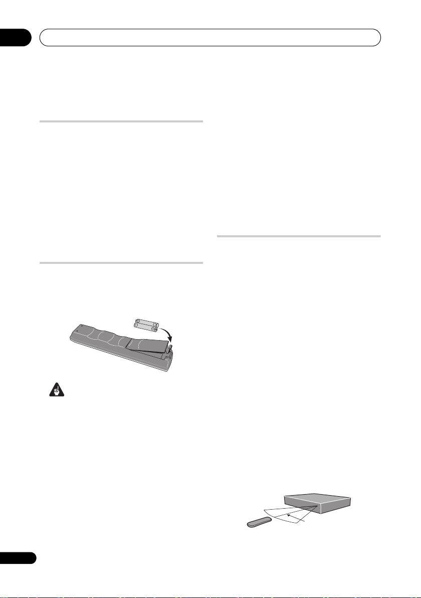
Putting the batteries in the
remote control
• Insert two AA/R6P batteries into the
battery compartment following the
indications (,) inside the
compartment.
Important
Incorrect use of batteries can result in
hazards such as leakage and bursting.
Please observe the following:
• Don’t mix new and old batteries
together.
• Don’t use different kinds of batteries
together — although they may look
similar, different batteries may have
different voltages.
• Make sure that the plus and minus ends
of each battery match the indications in
the battery compartment.
• Remove batteries from equipment that
isn’t going to be used for a month or
6
En
more.
• When disposing of used batteries,
please comply with governmental
regulations or environmental public
instruction’s rules that apply in your
country or area.
Do not use or store batteries in direct sunlight or
other excessively hot place, such as inside a car or
near a heater. This can cause batteries to leak,
overheat, explode or catch fire. It can also reduce the
life or performance of batteries.
WARNING
D3-4-2-3-3_En
Using the remote control
Please keep in mind the following when
using the remote control:
• Make sure that there are no obstacles
between the remote and the remote
sensor on the unit.
• Remote operation may become
unreliable if strong sunlight or
fluorescent light is shining on the unit’s
remote sensor.
• Remote controllers for different devices
can interfere with each other. Avoid
using remotes for other equipment
located close to this unit.
• Replace the batteries when you notice a
fall off in the operating range of the
remote.
• When the batteries run down or you
change the batteries, the remote control
mode is reset to Recorder 1. See Remote
Control Mode on page 118.
• Use within the operating range in front of
the remote control sensor on the front
panel, as shown.
7 m

Before you start
01
• You can control this recorder using the
remote sensor of another Pioneer
component via the CONTROL IN jack on
the rear panel. See Rear panel
connections on page 14 for more
information.
Disc/content format playback
compatibility
Compatible media
• DVD-RW ver. 1.1 / 1x / 1x to 2x, ver. 1.2 /
2x to 4x / 2x to 6x
• DVD-R ver. 2.0 / 1x / 1x to 4x / 1x to 8x /
1x to 16x, ver. 2.1 / 1x to 8x / 1x to 16x
• DVD+RW 1x to 2.4x / 1x to 4x / 3.3x to 8x
• DVD+R 1x to 2.4x / 1x to 4x / 1x to 8x /
1x to 16x
• DVD-RAM ver. 2.0 / 2x, ver. 2.1 / 2x /
2x to 3x / 2x to 5x, ver. 2.2 / 2x / 2x to 3x /
2x to 5x
• DVD-R DL ver. 3.0 / 2x to 4x / 2x to 8x
• DVD+R DL 2.4x / 2.4x to 8x
Note that older models of DVD recorders and
DVD writers may reject DVD-RW ver. 1.2
discs and/or corrupt the data on the disc. If
you want to share DVD-RW discs between
this recorder and an older recorder/writer,
we recommend using ver. 1.1 discs.
The following table shows older Pioneer DVD
recorders’ limited compatibility with
DVD-RW ver. 1.2 discs.
Model Playable Recordable
DVR-7000
DVR-310
DVR-510H
*1
Discs should be finalized in this recorder before
playing. Unfinalized VR mode and Video mode discs
may not play.
*2
Cannot read the CPRM information will show in
the display when you load a disc. However, this will not
affect playback.
*3
Copy-once protected disc titles will not play.
Yes
Yes
*1,2,3
*1
No
No
Readable file system
This recorder can play DVDs recorded under
the following file systems
UDF 1.02, UDF 1.50, UDF 2.00, UDF 2.01.
* ISO 9660 Level 1 or 2 compliant. Romeo and
Joliet file systems are both compatible with
this recorder.
1
: ISO 9660*,
Note
1 • Depending on the recording technique used, even files recorded in compatible file systems may not play
correctly.
• MP3/WMA/DivX files can be played back when recorded onto a DVD that contains no video titles and uses the
UDF 1.02, UDF 1.50, UDF 2.01 or ISO 9660 file systems.
7
En
01
Before you start
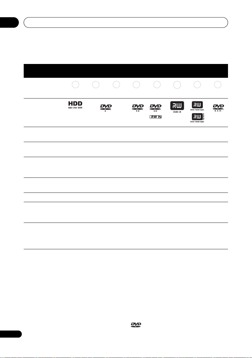
HDD/DVD Recording and playback compatibility
This recorder can play and record all widely-used DVD disc types, and additionally provides
HDD functionality. The table below shows some specific compatibility differences between
the different disc types.
HDD DVD-R DVD-RW DVD+R
Marks used in this
manual
Logos
HDD DVD ( VR) DVD (Video) DVD (VR) DVD (Video)
*1 *1 *2 *13, 16
DVD+R
DVD+RW DVD-RAM
DVD
+RW
DVD
-RAM
Re-recordable/
*3 *3 *3 *14
Erasable
Editing of recorded
*4 *4 *4 *4
programmes
Recording of Copy-
*12 *12 *12
once protected
material
Playback in other
n/a *5 *6 *7 *6
players/recorders
Chase play
16:9 and 4:3
programme
recording
Dual mono/
Bilingual broadcast
*10, 11
*11 *11 *11
recording of both
audio channels
Notes to table
*1 Must be initialized for VR mode recording
(page 103).
*2 Must be initialized for Video mode recording
(page 103).
*3 Erasable, but free space does not increase.
*4 Cannot erase sections, edit chapters or use playlist
editing.
*5 Must be compatible with DVD-R (VR) playback.
*6 Finalize using this recorder (may not playback in
some units) (page 48).
*7 Must be compatible with DVD-RW (VR) playback.
*8 Must be compatible with DVD+RW playback.
*9 Must be compatible with DVD-RAM playback.
*10 Only when HDD Recording Format is set to Video
8
Mode Off (page 115).
En
*6, 15
*8 *9
*11 Only when the recording mode is not set to LPCM.
*12 CPRM-compatible discs only.
*13 Take the disc out of the cartridge before use. Only
Panasonic and Maxell discs have been tested to work
reliably with this recorder. Discs from other makers may
become unusable when recorded or edited.
*14 Erasing a title does not increase the available
recording time, nor increase the number of recordable
titles left.
*15 Must be compatible with DVD+R playback.
*16 Depending on the disc, it may have to be initialized
before it can be recorded (page 103). In this case,
initialization will take about an hour.
is a trademark of DVD Format/Logo
Licensing Corporation.
Before you start
01
Using DVD-R DL/DVD+R DL discs
DVD-R DL (Dual-Layer) and DVD+R DL
(Double-Layer) discs contain two recordable
layers on a single side, giving about
1.8 times the recording capacity of a
conventional single-layer disc. This unit can
record to both DVD-R DL and DVD+R DL
discs.
• If you intend to play DVD-R DL (Video
mode) or DVD+R DL discs recorded on
this unit on other DVD recorders/players,
you must finalize them. (Note that some
DVD recorders/players may not play
even finalized DL discs.)
• This logo indicates that the disc is a
DVD-R DL or DVD+R DL disc:
Correct operation has been confirmed for DL
discs:
• DVD-R DL ver. 3.0/2x to 4x
Mitsubishi Kagaku Media (Verbatim)
• DVD-R DL ver. 3.0/2x to 8x
Mitsubishi Kagaku Media (Verbatim)
That’s
JVC
• DVD+R DL 2.4x
Mitsubishi Kagaku Media (Verbatim)
RICOH
• DVD+R DL 2.4x to 8x
Mitsubishi Kagaku Media (Verbatim)
RICOH
About DualDisc playback
A DualDisc is a new two -sided disc, one side
of which contains DVD content – video,
audio, etc. – while the other side contains
non-DVD content such as digital audio
material.
The non-DVD, audio side of the disc is not
compliant with the CD audio specification
and therefore may not play.
It is possible that when loading or ejecting a
DualDisc, the opposite side to that being
played will be scratched. Scratched discs
may not be playable.
The DVD side of a DualDisc plays in this
product. DVD-Audio content will not play.
For more detailed information on the
DualDisc specification, please refer to the
disc manufacturer or disc retailer.
Other disc compatibility
In addition to DVD, this recorder is
compatible with a wide range of disc types
(media) and formats. Playable discs will
generally feature one of the logos on the disc
and/or disc packaging shown below. Note
however that some disc types, such as
recordable CD (and DVD), may be in an
unplayable format — see below for further
compatibility information.
Audio CD CD-R CD-RW
Video CD
Super Video CD (Super VCD)
CD-R/-RW compatibility
This recorder cannot record CD-R or CD-RW
discs.
• Readable formats: CD audio, Video CD/
Super VCD, ISO 9660 CD-ROM*
containing MP3, WMA, JPEG or DivX
files
* ISO 9660 Level 1 or 2 compliant. CD
physical format: Mode1, Mode2 XA Form1.
Romeo and Joliet file systems are both
compatible with this recorder.
• Multi-session playback: Yes (except CD
audio and Video CD/Super VCD)
• Unfinalized disc playback: CD audio only
Compressed audio compatibility
• Compatible media: DVD-ROM,
DVD-R/-RW, DVD+R/+RW, DVD-RAM,
CD-ROM, CD-R, CD-RW, USB
• Compatible formats: MPEG-1 Audio
Layer 3 (MP3), Windows Media Audio
(WMA)
9
En

01
Before you start
• Sampling rates: 32 kHz, 44.1 kHz or
48 kHz
• Bit-rates: Any (128 kbps or higher
recommended)
• Variable bit-rate (VBR) MP3 playback:
Yes
• VBR WMA playback: No
• WMA encoder compatibility: Windows
Media Codec 8 (files encoded using
Windows Media Codec 9 may be playable
but some parts of the specification are not
supported; specifically, Pro, Lossless,
Voice and VBR)
1
• DRM (Digital Rights Management)
file
playback: No
• File extensions: .mp3, .wma (these must
be used for the recorder to recognize
MP3 and WMA files – do not use for
other file types)
• File structure: The recorder can load up
to 99 folders/999 files at one time (if there
are more files/folders that this on the disc
then more can be reloaded)
WMA (Windows Media™ Audio)
content
This recorder can playback Windows Media
Audio content.
WMA is an acronym for Windows Media
Audio and refers to an audio compression
technology developed by Microsoft
Corporation.
Windows Media is a trademark of Microsoft
Corporation.
This product includes technology owned by
Microsoft Corporation and cannot be used or
distributed without a license from Microsoft
Licensing, Inc.
DivX video compatibility
DivX is a compressed digital video format
created by the DivX
Inc. Keeping the same terminology as
DVD-Video, individual DivX video files are
called “Titles”. When naming files/titles on a
disc prior to burning, keep in mind that by
default they will be played in alphabetical
order.
• Official DivX
• Plays all versions of DivX
(including DivX
playback of DivX
• File extensions: .avi and .divx (these
must be used for the recorder to
recognize DivX video files). Note that all
files with the .avi extension are recognized
as MPEG4, but not all of these are
necessarily DivX video files and therefore
may not be playable on this recorder.
• File structure: Up to 99 folders or
999 files.
DivX, DivX Certified, and associated logos are
trademarks of DivX, Inc. and are used under
license.
®
video codec from DivX,
®
Certified product.
®
6) with standard
®
®
video
media files.
DivX® VOD content
DivX
In order to play DivX VOD (video on demand)
content on this recorder, you first need to
register the recorder with your DivX VOD
content provider. You do this by generating a
DivX VOD registration code, which you
submit to your provider.
Note
1 DRM (digital rights management) copy protection is a technology designed to prevent unauthorized copying by
restricting playback, etc. of compressed audio files on devices other than the PC (or other recording equipment)
used to record it. For detailed information, please see the instruction manuals or help files that came with your
10
PC and/or software.
En
Before you start
01
Some DivX VOD content may only be
playable a fixed number of times. When you
load a disc containing this type of DivX VOD
content, the remaining number of plays is
shown on-screen and you then have the
option of playing the disc (thereby using up
one of the remaining plays), or stopping. If
you load a disc that contains expired DivX
VOD content (for example, content that has
zero remaining plays), the message Rental
Expired is displayed.
If your DivX VOD content allows an unlimited
number of plays, then you may load the disc
into your recorder and play the content as
often as you like, and no message will be
displayed.
Important
• DivX VOD content is protected by a DRM
system. This restricts playback of
content to specific, registered devices.
• If you load a disc that contains DivX VOD
content not authorized for this recorder,
the message Authorization Error is
displayed and the content will not play.
• Resetting the recorder (as described in
Resetting the recorder on page 136) will
not cause you to lose your registration
code.
PC-created disc compatibility
Discs recorded using a personal computer
may not be playable in this unit due to the
setting of the application software used to
create the disc. In these particular
instances, check with the software publisher
for more detailed information.
Discs recorded in packet write mode (UDF
format) are not compatible with this
recorder.
Check the DVD-R/-RW or CD-R/-RW
software disc boxes for additional
compatibility information.
Dolby Digital
Manufactured under license from Dolby
Laboratories. “Dolby” and the double-D
symbol are trademarks of Dolby Laboratories.
DTS
JPEG file compatibility
• Compatible formats: Baseline JPEG and
EXIF 2.2* still image files
*File format used by digital still cameras
• Sampling ratio: 4:4:4, 4:2:2, 4:2:0
• Horizontal resolution: 160 to 5120 pixels
• Vertical resolution: 120 to 3840 pixels
• Progressive JPEG compatible: No
• File extensions: .jpg, .jpeg, .jpe, .jif, .jfif
(must be used for the recorder to
recognize JPEG files – do not use for
other file types)
• File structure: The recorder can load up
to 99 folders/999 files at one time (if there
are more files/folders that this on the disc
then more can be reloaded)
“DTS” and “DTS Digital Out” are registered
trademarks of DTS, Inc.
11
En

01
Before you start
About the internal hard disk
drive
The internal hard disk drive (HDD) is a fragile
piece of equipment. When used without the
proper care or in the wrong conditions, it is
possible that recorded contents may be
damaged or lost entirely, in some cases
making even normal playback or recording
impossible. Please understand that in the
event of repair or replacement of the HDD or
related components, all your HDD
recordings will be lost.
Please use the recorder following the
guidelines below to protect against possible
HDD failure.
The HDD should not be regarded as a place to
store recordings permanently. We
recommend that you back up your important
recordings onto DVD discs in order to protect
against accidental loss.
Pioneer cannot under any circumstances
accept responsibility for any direct or indirect
loss arising from any inconvenience or loss of
recorded material resulting from HDD failure.
• Install and use the recorder on a stable,
level surface.
• Do not block the rear vent/cooling fan.
• Do not use the recorder in excessively
hot or humid places, or in places that
may be subject to sudden changes in
temperature. Sudden changes in
temperature can cause condensation to
form inside the recorder. This can be a
cause of HDD failure.
• Do not move the recorder immediately
after switching it off. If you need to move
the recorder, please follow the steps
below:
1 After the message POWER OFF is
shown on the front panel display, wait at
least two minutes.
2 Unplug from the wall socket.
3 Move the recorder.
• If there’s a power failure while the
12
En
recorder is on there is a chance that
some data on the HDD will be lost.
• The HDD is very delicate. If used over
time in an improper manner or in an
unsuitable environment, it is possible
that the HDD will fail. Signs of problems
include playback unexpectedly freezing
and noticeable block noise (mosaic) in
the picture. However, sometimes there
will be no warning signs of HDD failure.
If the HDD fails, no playback of recorded
material will be possible. In this case it
will be necessary to replace the HDD
unit.
Optimizing HDD performance
As you record and edit material on the HDD,
the data on the disk becomes fragmented,
eventually affecting the recorder’s
performance. Before this happens, the
recorder will warn you that it is time to
optimize the HDD (which you can do from
the Disc Setup menu; see Optimize HDD on
page 103).

Before you start
Symbols used in this manual
The following icons are provided to help you
quickly identify which instructions you need
for which kind of disc.
01
HDD
DVD
DVD-Video
DVD (Video)
DVD (VR)
DVD+R
DVD+RW
DVD-RAM
CD
Video CD
Super VCD
HDD
Any type of DVD disc
(recordable or playback
only), finalized or not.
Commercially produced
DVD, finalized Video mode
DVD-R/-RW.
Video mode DVD-R/-RW
(unfinalized)
VR mode DVD-R/-RW
DVD+R
DVD+RW
DVD-RAM
Audio CD
Video CD
Super VCD
WMA/MP3
DivX
ALL
WMA or MP3 files
DivX files
All of the above
13
En
02
Connections
Chapter 2
Connections
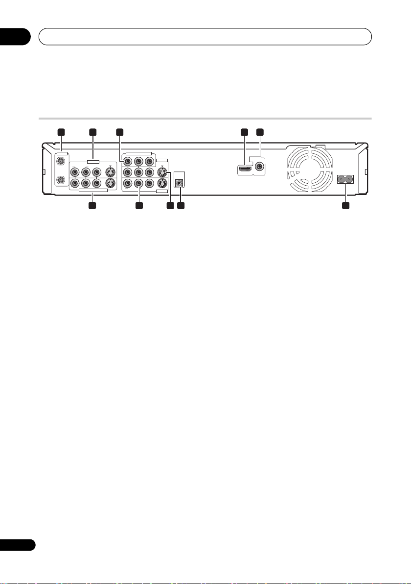
Rear panel connections
ANTENNA
1
IN
R
OUT
INPUT 1/AUTO START REC
INPUT 3
L
3 4 52
COMPONENT VIDEO OUT
P
B
Y
P
R
S-VIDEO
VIDEOAUDIO
R
OUTPUT 2
S-VIDEO
CONTROL
IN
L
AUDIO
VIDEO
OUTPUT 1
6 7 8 9
1 ANTENNA IN (RF IN)/OUT
Connect your TV antenna to the ANTENNA
IN (RF IN) jack. The signal is passed through
to the ANTENNA OUT jack for connection to
your TV.
2 INPUT 3
Stereo analog audio, video and S-Video
inputs for connection to a satellite receiver,
set top box, etc.
3 COMPONENT VIDEO OUT
A high-quality video output for connecting to
a TV or monitor with a component video
input.
4HDMI OUT
HDMI output for high quality digital audio
and video.
5 DIGITAL AUDIO OUT (COAXIAL)
Coaxial digital audio jack for connecting to
an AV amplifier/receiver, Dolby Digital/DTS
decoder or other equipment with a digital
input.
6 INPUT 1/AUTO START REC
Stereo analog audio, video and S-Video
inputs for connection to a satellite receiver,
set top box, etc.
DIGITAL
HDMI OUT
AUDIO OUT
COAXIAL
AC IN
10
7OUTPUT1
Stereo analog audio, video and S-Video
outputs for connection to a TV or AV
amplifier/receiver.
8OUTPUT2
Stereo analog audio, video and S-Video
outputs for connection to a TV or AV
amplifier/receiver.
9 CONTROL IN
Use to control this recorder from the remote
sensor of another Pioneer component with a
CONTROL OUT terminal and bearing the
Pioneer mark. Connect the CONTROL
OUT of the other component to the
CONTROL IN of this recorder using a mini-
plug cord.
10 AC IN – Power inlet
Connect to a power outlet using the supplied
power cable after making all other
connections.
14
En
Connections
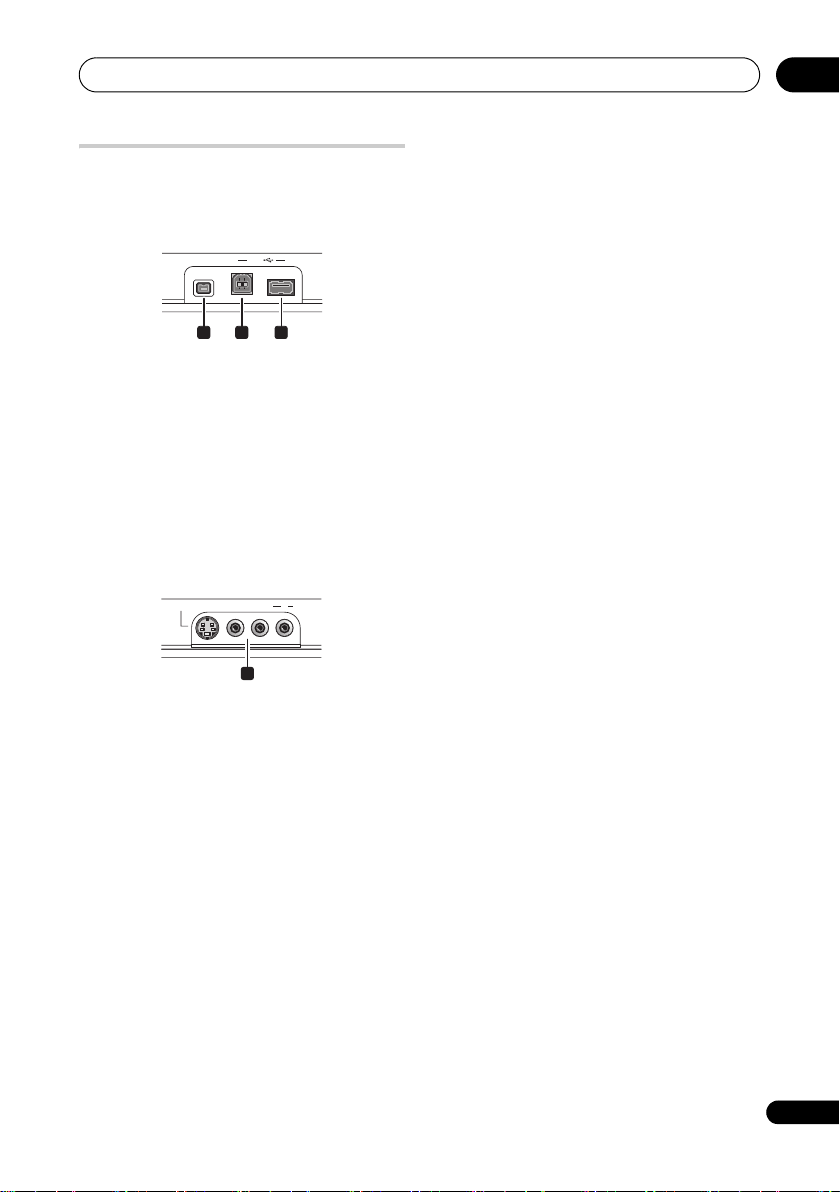
Front panel connections
On the front panel there is a flip-down cover
that hides more connections.
Left side:
DV IN
USB
11 12 13
11 DV IN
A DV input i.LINK connector, suitable for
connecting a DV camcorder.
12 USB port (Type B)
USB port for connecting a PictBridgecompatible printer or PC.
13 USB port (Type A)
USB port for connecting a digital camera,
keyboard or other USB device.
Right side:
S-VIDEO
VIDEO
INPUT 2
L(MONO) R AUDIO
02
14
14 INPUT 2
Audio/video input (stereo analog audio;
composite and S-Video), especially suitable
for camcorders, game consoles, portable
audio, etc.
15
En
02
Connections
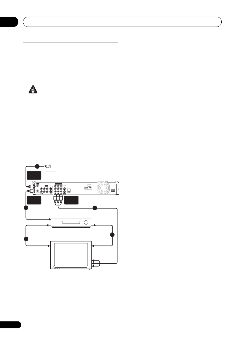
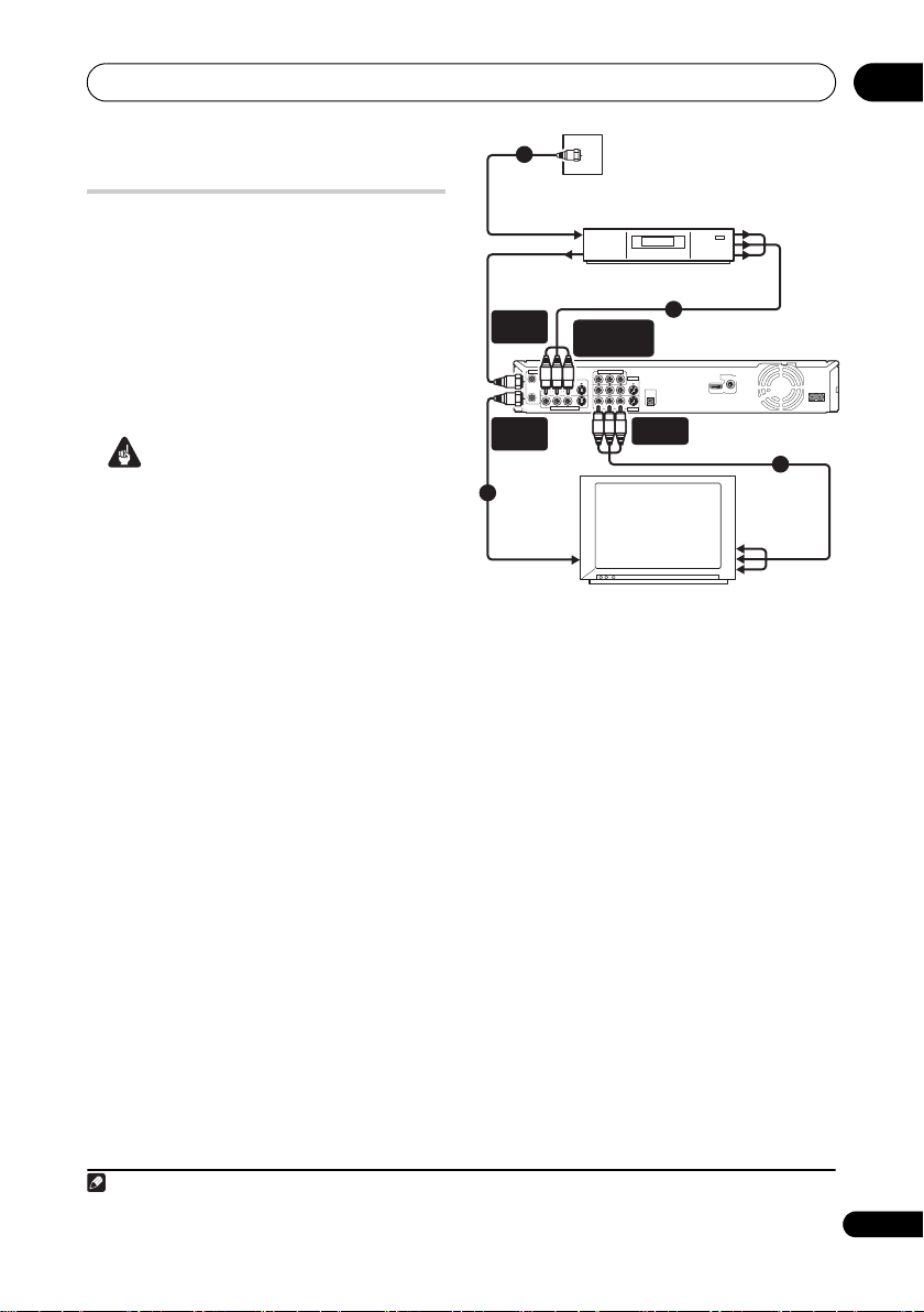
Easy connections
The setup described here is a basic
configuration that allows you to record TV
programmes on both this recorder and your
VCR. When watching recordings from this
recorder, set your TV to input 1; switch to
input 2 to watch a video playing in the VCR.
Important
• This recorder is equipped with copy
protection technology. Do not connect
this recorder to your TV via a VCR (or your
VCR via this recorder) using AV cables,
as the picture from this recorder will not
appear properly on your TV.
• Before making or changing any rear
panel connections, make sure that all
components are switched off and
unplugged from the wall outlet.
1
ANTENNA
IN
INPUT 3
R
OUT
INPUT 1/AUTO START REC
OUT
From antenna
output
Antenna/cable TV
wall outlet
COMPONENT VIDEO OUT
P
B
Y
P
R
S-VIDEO
VIDEOAUDIO
L
R
L
AUDIO
VIDEO
VCR
OUTPUT 2
S-VIDEO
CONTROL
IN
OUTPUT 1
OUTPUT 1
DIGITAL
AUDIO OUT
COAXIAL
HDMI OUT
4
From audio/
video output
To audio/
video input
To audio/
video input
AC IN
5
ANTENNA
IN (RF IN)
ANTENNA
2
To antenna input
3
To antenna input
1 Connect your TV antenna/cable TV
outlet to the ANTENNA IN (RF IN) jack on
this recorder.
2 Use an RF antenna cable (one is
supplied) to connect the ANTENNA OUT
jack on this recorder to the antenna input
on your VCR.
• If you are not connecting a VCR in the
chain, connect this recorder directly to
your TV and skip the next step.
3 Use an RF antenna cable to connect
the antenna output on your VCR to the
antenna input on your TV.
4 Connect the AUDIO and VIDEO
OUTPUT jacks (1 or 2) to a set of audio/
video inputs on your TV.
Use the supplied three-pin audio/video
cable. It is colour-coded to help you match
them up (red/white for the right/left audio
connections and yellow for video in/outs).
Make sure you match up the left and right
outputs with their corresponding inputs for
correct stereo sound.
5 Connect your VCR to your TV (A/V
IN 2 above) using a set of audio and
video cables.
• See the following page if you want to use
S-Video or component video cables for
the video connection.
16
En
TV
Connections
02
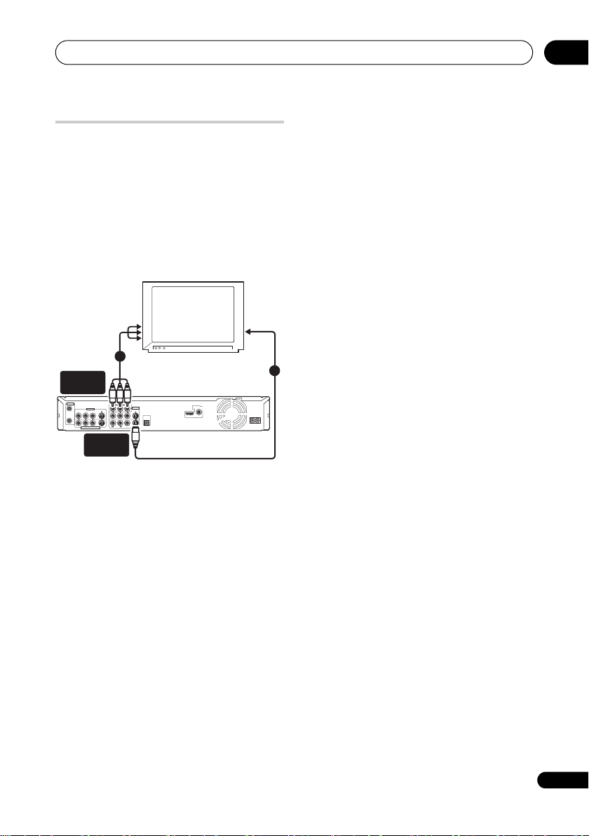
Using other types of video
output
This recorder has standard (composite),
S-Video and component video outputs. The
main difference between them is the quality
of the picture. S-Video delivers a better
picture than composite video, while
component video gives better picture quality
still. The variety of outputs also gives you the
flexibility of connecting your particular
equipment using the best connection type
available.
To component
COMPONENT
VIDEO OUT
ANTENNA
IN
INPUT 3
VIDEOAUDIO
R
L
OUT
INPUT 1/AUTO START REC
video input
COMPONENT VIDEO OUT
P
R
S-VIDEO
R
AUDIO
S-VIDEO
OUTPUT
2
TV
P
B
Y
OUTPUT 2
S-VIDEO
CONTROL
IN
L
VIDEO
OUTPUT 1
DIGITAL
AUDIO OUT
COAXIAL
HDMI OUT
To S-Video
input
AC IN
1
1 Connecting using an S-Video output
S-Video carries the picture as separate
colour and luminance (brightness) signals.
There are two S-Video outputs for
connection to TVs, monitors, VCRs or other
equipment.
• Use an S-Video cable (not supplied) to
connect an S-VIDEO OUTPUT (1 or 2) to
an S-Video input on your TV, monitor (or
other equipment).
2 Connecting using the component
video output.
Component video carries the picture as two
separate colour signals, plus a luminance
(brightness) signal.
See also Component Video Out on page 110
for how to set up the component video
output for use with a progressive scancompatible TV.
• Use a component video cable (not
supplied) to connect the COMPONENT
VIDEO OUT jacks to a component video
input on your TV, monitor (or other
equipment).
17
En
02
Connections
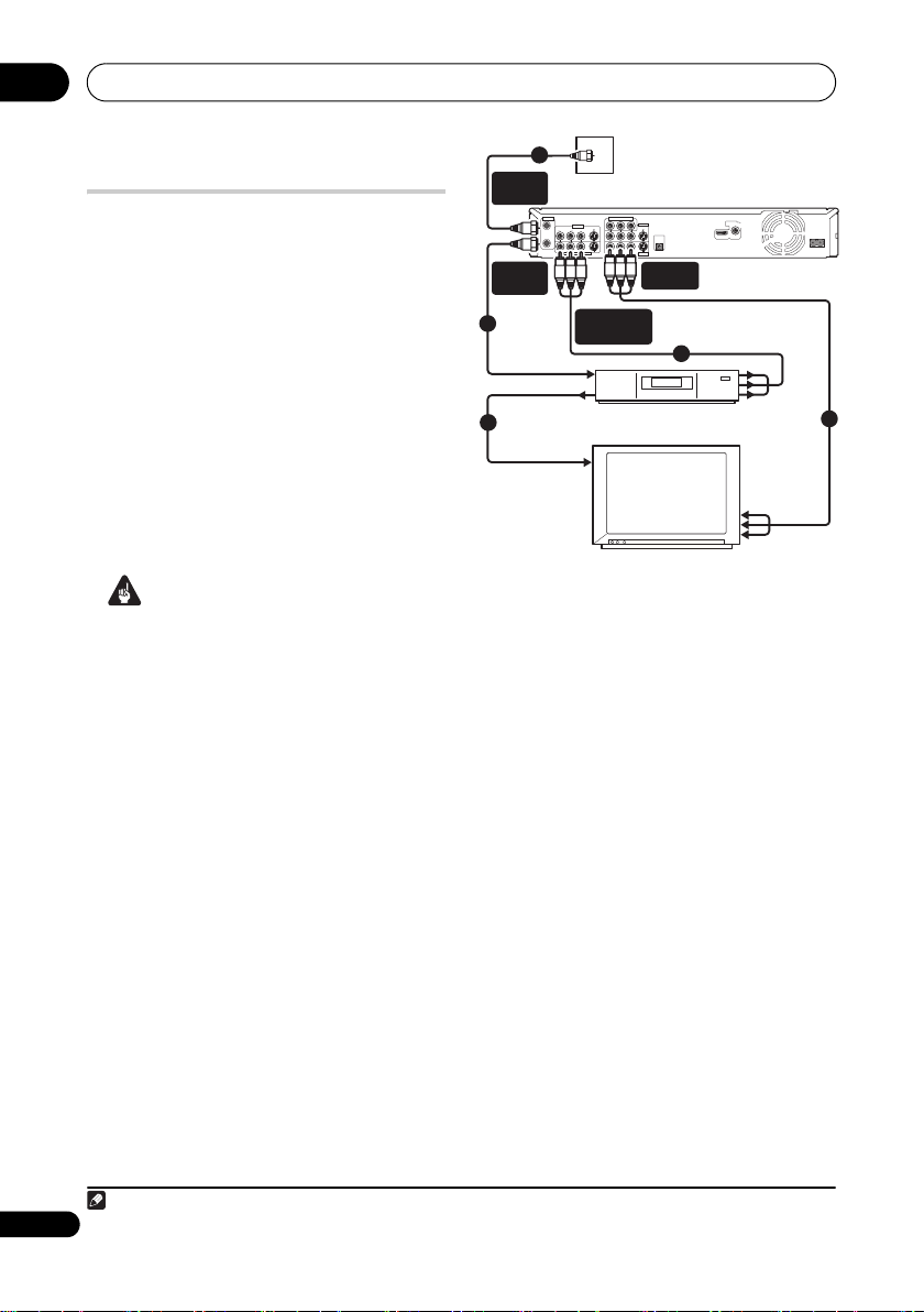
Connecting to a cable box or
satellite receiver (1)
If you are using a cable box or satellite
rec ei ve r w it h o nl y a few scrambled channels,
follow the setup on this page
the channels are scrambled, we recommend
using the setup on the following page.
Using the setup on this page you can:
• Record unscrambled channels by
selecting them on this recorder.
• Record scrambled channels by selecting
them on the cable box/satellite receiver
and using the Auto Start Recording
feature (see Automatic recording from a
satellite tuner on page 47).
• Watch one channel while recording
another.
Important
• Do not connect this recorder ‘through’
your VCR, satellite receiver or cable box.
Always connect each component
directly to your TV or AV amplifier/
receiver.
1
. If many or all
INPUT 3
S-VIDEO
VIDEOAUDIO
R
L
INPUT 1/AUTO START REC
INPUT 1/AUTO
START REC
Cable box/
Satellite receiver
Antenna/cable TV
wall outlet
COMPONENT VIDEO OUT
P
B
Y
P
R
OUTPUT 2
S-VIDEO
CONTROL
IN
R
L
AUDIO
VIDEO
OUTPUT 1
OUTPUT 1
DIGITAL
AUDIO OUT
COAXIAL
HDMI OUT
AC IN
3
From audio/
video output
To audio/
video input
ANTENNA
IN (RF IN)
ANTENNA
OUT
1
To antenna
input
From antenna
output
1
To antenna
1
ANTENNA
OUT
input
IN
TV
1 Connect RF antenna cables as shown.
This enables you to watch and record TV
channels.
2 Connect the AUDIO and VIDEO
OUTPUT jacks (1 or 2) on this recorder to
a set of audio/video inputs on your TV
using a set of A/V cables (as supplied).
This enables you to watch the output from
this recorder.
3 Connect the audio/video output of
your cable box/satellite receiver to the
INPUT 1 jacks on this recorder using a set
of A/V cables.
This enables you to record scrambled TV
channels.
2
Note
1 The diagram shows standard video connections, but you can alternatively use the S-Video or component video
18
connections if they’re available.
En
Connections
02
Connecting to a cable box or
satellite receiver (2)
If many or all the channels you receive by
cable or satellite are scrambled, we
recommend using this setup.
Using the setup on this page you can:
• Record any channel by selecting it on
the cable box/satellite receiver.
• Record using the Auto Start Recording
feature (see Automatic recording from a
satellite tuner on page 47).
Important
• Do not connect this recorder ‘through’
your VCR, satellite receiver or cable box.
Always connect each component
directly to your TV or AV amplifier/
receiver.
1
Cable box/
Satellite receiver
INPUT 1/AUTO
INPUT 3
S-VIDEO
VIDEOAUDIO
L
INPUT 1/AUTO START REC
Antenna/cable TV
wall outlet
START REC
COMPONENT VIDEO OUT
B
P
Y
P
R
OUTPUT 2
S-VIDEO
R
L
AUDIO
VIDEO
OUTPUT 1
CONTROL
IN
OUTPUT 1
From audio/
video output
3
DIGITAL
AUDIO OUT
COAXIAL
HDMI OUT
AC IN
1
To antenna
input
From antenna
output
ANTENNA
IN (RF IN)
ANTENNA
IN
R
OUT
ANTENNA
OUT
2
1
To antenna
input
To audio/
video input
TV
1 Connect RF antenna cables as shown.
This enables you to watch and record TV
channels.
2 Connect the AUDIO and VIDEO
OUTPUT jacks (1 or 2) on this recorder to
a set of audio/video inputs on your TV
using a set of A/V cables (as supplied).
This enables you to watch discs.
3 Connect the audio/video output of
your cable box/satellite receiver to the
INPUT 1 jacks on this recorder using a set
of A/V cables.
This enables you to record scrambled TV
channels.
Note
1 • The setup on this page does not allow you to watch one channel and record another.
• The diagram shows standard video connections, but you can alternatively use the S-Video or component video
connections if they’re available.
19
En
02
Connections
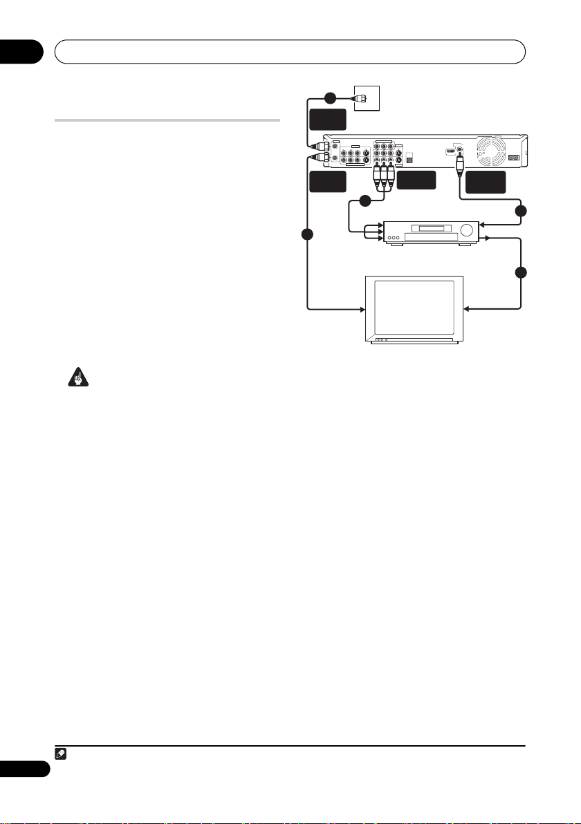
Connecting to an AV
amplifier or receiver
To enjoy multichannel surround sound you
need to connect this recorder to an AV
amplifier/receiver using the digital coaxial
output. In addition to the digital connection,
we recommend also connecting using the
stereo analog connection.
You’ll probably also want to connect a video
output to your AV amplifier/receiver. Use the
standard (composite) video output (as
shown here), or the S-Video or component
video connections.
See also Audio Out on page 111 for how to
set up the digital audio output. (Noise may
be output from your speakers if the recorder
is not set up to work with your AV amplifier/
receiver.)
Important
• Do not connect this recorder to your TV
‘through’ your VCR or other component
using A/V cables. Always connect it
directly to your TV.
1
ANTENNA
IN (RF IN)
ANTENNA
OUT
ANTENNA
IN
R
OUT
Antenna/cable TV
wall outlet
COMPONENT VIDEO OUT
B
P
Y
P
R
OUTPUT 2
S-VIDEO
S-VIDEO
VIDEOAUDIO
R
L
AUDIO
VIDEO
OUTPUT 1
INPUT 1/AUTO START REC
INPUT 3
L
2
To audio/video input
CONTROL
IN
OUTPUT 1
HDMI OUT
DIGITAL
AUDIO OUT
COAXIAL
DIGITAL
AUDIO OUT
To digital
input
AC IN
1
From video
output
To video
input
To antenna
input
AV amplifier/receiver
TV
1 Connect RF antenna cables as shown.
This enables you to watch and record TV
channels.
2 Connect the AUDIO and VIDEO
OUTPUT jacks (1 or 2) on this recorder to
a set of audio/video inputs on your AV
amplifier/receiver.
3 Use an coaxial digital audio cable (not
supplied) to connect the DIGITAL AUDIO
OUT (COAXIAL) jack on this recorder to
an coaxial digital input on your AV
amplifier/receiver.
This enables you to listen to multichannel
surround sound.
1
4 Connect the AV amplifier/receiver’s
video output to a video input on your TV.
3
4
Note
1 If your AV amplifier/receiver doesn’t have an coaxial digital input, but has a optical type, converter boxes that
20
convert from coaxial to optical are available at specialist audio dealers.
En
Connections
02
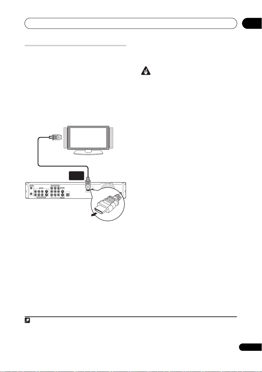
Connecting using HDMI
If you have an HDMI or DVI-equipped1
monitor or display
this recorder using an HDMI cable
supplied).
The HDMI connector outputs uncompressed
digital video, as well as almost every kind of
digital audio.
1 Use an HDMI cable to connect the
HDMI OUT connector on this recorder to
an HDMI connector on an HDMIcompatible display.
ANTENNA
IN
INPUT 3
S-VIDEO
VIDEOAUDIO
R
L
OUT
INPUT 1/AUTO START REC
• The arrow on the cable connector body
should be face down for correct
alignment with the connector on the
recorder.
When connected to an HDMI component or
HDCP-compatible DVI component, the
HDMI indicator lights.
HDMI setup is generally automatic. There
are however settings you can change if you
need to. See HDMI Output (only available
when an HDMI device is connected) on
2
, you can connect it to
To HDMI
input
HDMI-compatible display
HDMI
OUT
COMPONENT VIDEO OUT
B
P
Y
P
R
OUTPUT 2
S-VIDEO
CONTROL
IN
R
L
AUDIO
VIDEO
OUTPUT 1
3
(not
DIGITAL
AUDIO OUT
COAXIAL
HDMI OUT
AC IN
page 116 for more information. Note that the
HDMI settings remain in effect until you
change them, or connect a new HDMI
component.
Important
• An HDMI connection can only be made
with DVI-equipped components
compatible with both DVI and
High-bandwidth Digital Content
Protection (HDCP). If you choose to
connect to a DVI connector, you will
need a DVI to HDMI adaptor cable. A DVI
to HDCP connection, however, does not
support audio. Consult your local audio
dealer for more information.
• The HDMI connection is compatible with
32 kHz, 44.1 kHz, 48 kHz, 96 kHz, 16 bit/
20 bit/24 bit 2-channel linear PCM
signals, as well as Dolby Digital, DTS and
MPEG audio bitstream.
• If your connected component is only
compatible with Linear PCM, the signal
is output as Linear PCM (DTS audio is
not output).
• If you have connected to a Pioneer
plasma display, please select the HDMI
setup on the display (refer to the
supplied manual for more on this).
About HDMI
HDMI (High-Definition Multimedia
Interface) supports both video and audio on
a single digital connection for use with DVD
players and recorders, DTV, set-top boxes,
and other AV devices. HDMI was developed
to provide the technologies of
High-bandwidth Digital Content Protection
(HDCP) as well as Digital Visual Interface
(DVI) in one specification. HDCP is used to
protect digital content transmitted and
received by DVI-compliant displays.
Note
1 Depending on the component you have connected, using a DVI connection may result in unreliable signal
transfers.
2 The pixel resolution of this recorder’s HDMI video output is (according to TV format): NTSC (720 x 480i/p,
1280 x 720p, 1920 x 1080i/p) and PAL (720 x 576i/p, 1280 x 720p, 1920 x 1080i/p). If your display is not compatible
with these resolutions the picture may not be correctly reproduced.
3 We recommend you use an HDMI cable that supports HDMI category 2.
21
En

02
Connections
HDMI has the capability to support
standard, enhanced, or high-definition video
plus standard to multi-channel surroundsound audio. HDMI features include
uncompressed digital video, a bandwidth of
up to five gigabits per second (Dual Link),
one connector (instead of several cables and
connectors), and communication between
the AV source and AV devices such as DTVs.
HDMI, the HDMI logo and High-Definition
Multimedia Interface are trademarks or
registered trademarks of HDMI Licensing LLC.
HDMI Control
By connecting this unit to an HDMI Controlcompatible Pioneer plasma television, AV
system (amplifier or AV receiver etc.) with an
HDMI cable, you can control this unit from
the remote control of a connected plasma
television, as well as have the connected
plasma television automatically change
inputs in response to this unit starting
playback.
Refer to the operating instructions for your
plasma television or AV system for more
information about which operations can be
carried out by connecting via HDMI cable.
Auto-select function
You can have a connected plasma television
or AV system automatically change inputs
when playback begins on this unit (including
when you have a GUI (such as Disc
Navigator) set to display on this unit).
Certain connected plasma televisions may
have their power turned from off to on when
using this function.
Simultaneous power function
You can have this unit turn on automatically
when the power for a connected plasma
television is turned on. To have this unit’s
power turned off when a connected plasma
television is turned off, you must change the
simultaneous power function of your plasma
television.
Unified language function
By receiving language information from a
22
En
connected plasma television, you can have
this unit’s language settings automatically
change to those of the plasma television
(language information can be received only
when no media is being played back and no
recordings are taking place, or when you
choose not to display this unit’s GUI
displays).
Important
• Depending on the type of plasma
television, some HDMI input terminals
do not support the HDMI Control
function. For details, see the operating
instructions supplied with your plasma
television.
• To use the following functions, set this
unit’s HDMI Control to Off (page 117).
– When you use Auto Start Recording
(page 47).
– When you want this unit to
automatically switch off upon
completion of timer recording. (When
HDMI Control is set to On, this unit
does not automatically switch off if your
plasma television is switched on upon
completion of timer recording.)
– When using the Video Control function
of an external component.
– Child lock settings (page 45).
• HDMI Control may not operate properly
if you do not use an HDMI cable that
supports the HDMI 1.3 Specification.
• Controls may not function properly in
certain situations, such as immediately
after you have connect an HDMI cable,
turn this unit’s power off or remove the
power cable for this unit or the
connected component. If you experience
any problems, set HDMI Control to On
for all connected units, and then display
the pictures stored on this unit on your
plasma television to improve the
situations.
• We cannot guarantee this unit will work
with HDMI Control-compatible
components other than those made by
Pioneer.
Connections
02
Connecting other AV sources
Connecting a VCR or analog
camcorder
HDD/DVD
DivX
COPY HDMI
STANDBY/ON
DV IN
USB
AUDIO/VIDEO
OUTPUT
(Rear panel)
1 2
To audio/
video input
Analog camcorder
VCR
1 Connect a set of audio and video
inputs of your VCR or camcorder to a set
of outputs on this recorder.
This enables you to record from this recorder
to your VCR or camcorder.
• You can use standard video or S-Video
cables for the video connection.
2 Connect a set of audio and video
outputs of your VCR or camcorder to a
set of inputs on this recorder.
This enables you to record tapes from your
VCR or camcorder.
• You can use standard video or S-Video
cables for the video connection.
• The front panel connections make
convenient connections for a camcorder
input.
• When connecting an external AV source
that only supports monaural sound, only
insert the left (white) audio jack to this
device. Doing so will allow the same
sound track to be recorded to both
channels. You must connect to the
INPUT 2 jack on the front panel.
OPEN/CLOSE
ONE TOUCH
STOP REC
COPY
INPUT
REC MODE
CH
SELECT
AUDIO/VIDEO
INPUT
(Front panel)
S-VIDEO
VIDEO
L(MONO)RAUDIO
INPUT 2
From audio/
video output
REC
Connecting a DV camcorder
You can connect a DV camcorder or DVD
recorder with DV output to the front panel
DV IN jack.
Important
• This jack is for connection to DV
equipment only. It is not compatible with
digital satellite receivers or D-VHS video
decks.
HDD/DVD
DivX
COPY HDMI
STANDBY/ON
DV IN
USB
DV
IN
From DV output
OPEN/CLOSE
S-VIDEO
VIDEO
L(MONO)RAUDIO
INPUT 2
ONE TOUCH
STOP REC
COPY
INPUT
REC MODE
CH
SELECT
REC
DV camcorder
• Use a DV cable (not supplied) to
connect the DV jack of your DV
camcorder to the front panel DV IN
jack of this recorder.
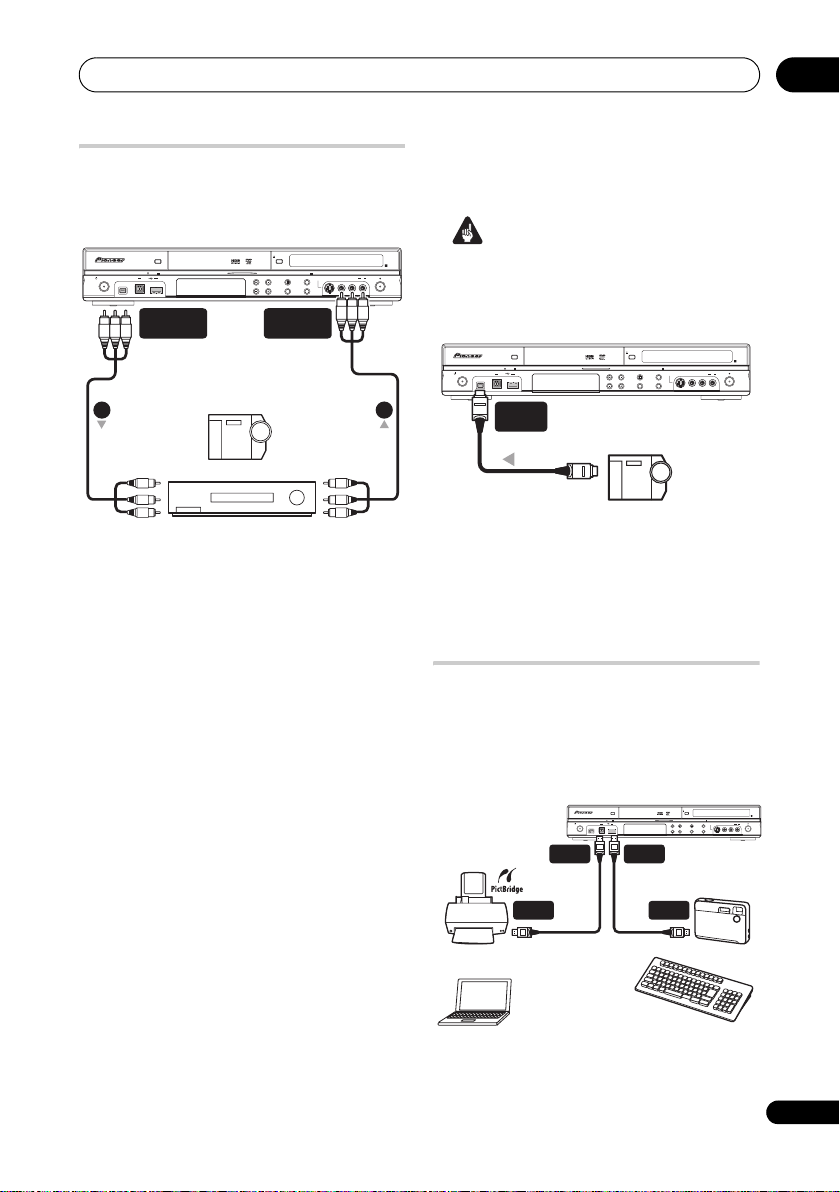
Connecting a USB device
Using the USB ports on the front of the
recorder you can connect USB devices such
as digital cameras, printers, keyboards and
PCs. Please also see the instructions that
came with the device you want to connect
before using.
USB
PictBridge-compatible
Printer
PC
USB
(Type B)
HDD/DVD
DivX
COPY HDMI
STANDBY/ON
DV IN
USB
(Type A)
USB
CH
USB
Keyboard
OPEN/CLOSE
S-VIDEO
VIDEO
L(MONO)RAUDIO
INPUT 2
ONE TOUCH
STOP REC
COPY
INPUT
REC MODE
SELECT
Digital Camera
REC
23
En

02
Connections
Important
• Some USB devices may not work with
this recorder.
• When connecting a PC to this unit, make
sure the power is turned off on both the
PC and this unit when you connect them
via USB.
• We recommend connecting USB
devices when this recorder is switched
off (in standby).
JPEG file storage devices
• Digital still camera
• Memory card reader (any type of memory
card)
•USB memory
The Mass Storage Class (MSC) device
should be FAT-compatible. Note that if the
device is partitioned, this recorder may not
recognize it.
The Picture Transfer Protocol (PTP) can be
used to transfer up to a maximum of 4000
files.
WMA/MP3 file storage devices
• Memory card reader (any type of memory
card)
•USB memory
• PC (Use Connect PC function)
The Mass Storage Class (MSC) device
should be FAT-compatible. Note that if the
device is partitioned, this recorder may not
recognize it.
Note that although multi-slot card readers
can be used, the recorder will only recognize
the first card inserted. To read another card,
remove all the cards and insert the card to be
read again.
Using a USB hub
• Use a hub compatible with USB 1.1 and/
or 2.0.
• Use an independently powered hub (bus
powered hubs may not work reliably).
• In the event of unreliable operation with
the hub, we recommend plugging the
device directly into the recorder’s USB
port.
• Operation may become unreliable if too
many devices are connected to the hub.
In this case, try unplugging some
devices.
• If the power delivered through a hub is
insufficient for the devices connected,
communication can become unreliable.
In this case, disconnect one or more
devices then perform a USB restart. (See
Restart USB Device on page 118.)
Using a USB printer
• Use a PictBridge-compatible printer.
Using a USB keyboard
• Do not use a PS/2 keyboard connected
using a PS/2-USB adapter.
Using a PC
• Note that you can connect a PC to this
device via USB to copy WMA and MP3
files. For more information, see Connect
PC on page 88. To use Connect PC with
this device, your PC must run either the
Windows XP Home Edition (SP2),
Windows XP Professional (SP2) or
Windows Vista Home Premium
operating system and be able to run
Windows Media Player 11. Even if your
PC can run Windows Media Player 11,
we cannot guarantee that it will function
properly with this device. For more
details see the ‘Help’ section of Windows
Media Player 11.
Plugging in
After checking all the connections, plug in
the recorder.
• Use the supplied power cable to
connect this recorder to a power outlet.
24
En
Controls and displays
Chapter 3
Controls and displays
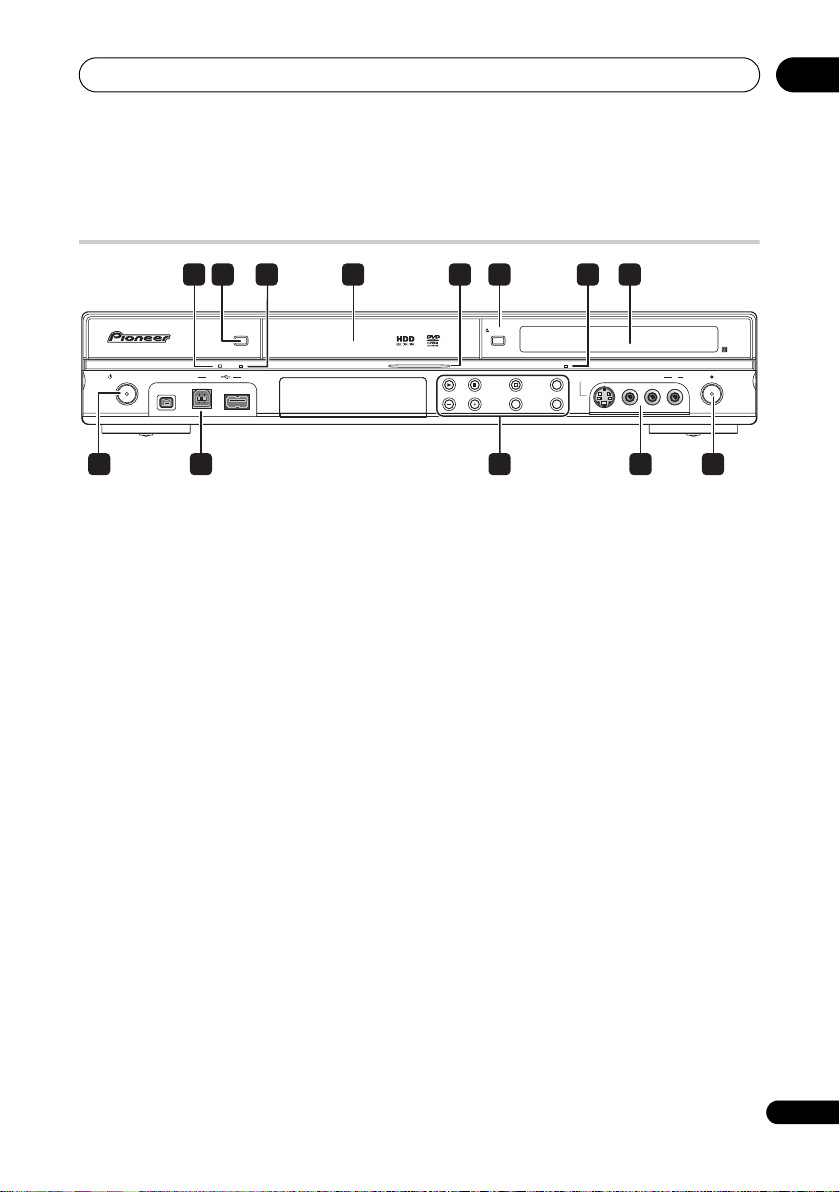
Front panel
03
84 61 732 5
HDD/DVD
DivX
COPY HDMI
STANDBY/ON
DV IN
USB
1 DivX indicator
Lights when this recorder plays DivX video
files.
2 HDD/DVD
Press to switch between HDD and DVD for
recording and playback.
3COPY indicator
Lights when copying is underway.
4 Disc tray
5 HDD/DVD indicator
Indicator lights blue when the hard disk
(HDD) is selected; orange when the DVD
drive is selected.
6 OPEN/CLOSE
Press to open/close the disc tray.
7HDMI indicator
Lights when this recorder is connected to
HDMI (HDCP) compatible component.
8 Front panel display and IR remote
sensor
See Display on page 26 for details.
9 STANDBY/ON
Press to switch the recorder on/into standby.
10 Front panel inputs
See Front panel connections on page 15 for
more information on these.
OPEN/CLOSE
S-VIDEO
VIDEO
INPUT 2
ONE TOUCH
STOP REC
COPY
INPUT
SELECT
REC MODE
CH
L(MONO)RAUDIO
REC
12109 10 11
11
Press to start or restart playback.
Press to stop playback.
F STOP REC
Press to stop recording.
ONE TOUCH COPY
Press to start One Touch Copy of the
currently playing title to DVD or the HDD.
CH +/–
Use to change channels, skip chapters/
tracks, etc.
INPUT SELECT
Press to change the input used for
recording.
REC MODE
Press repeatedly to cycle through
recording modes (picture quality).
12 REC
Press to start recording. Press repeatedly to
set the recording time in 30 minute blocks.
25
En
03
Controls and displays
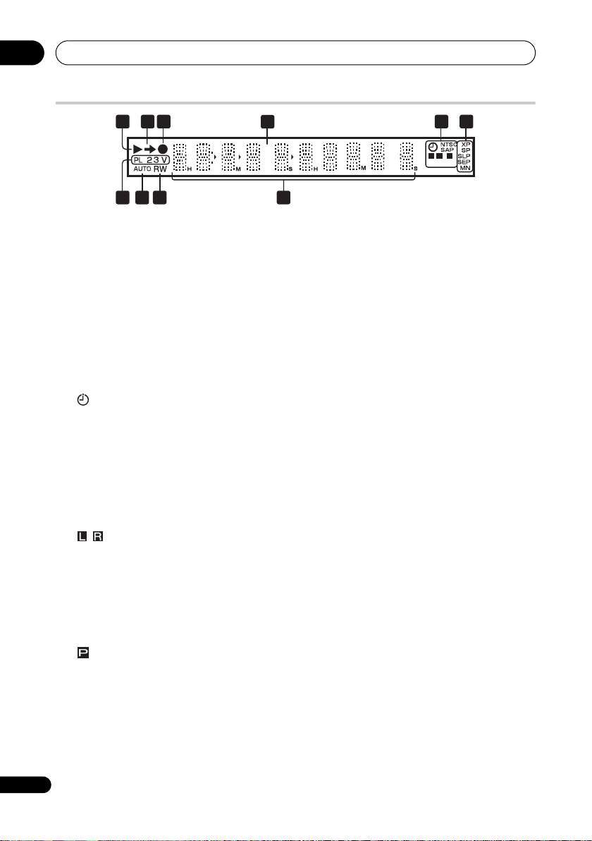
Display
2 3 5 61
89 7
10
1
Lights during playback; blinks when
playback is paused.
2
Lights when copying.
3
Lights during recording; blinks when
recording is paused.
4PM
Lights to indicate PM (after midday) for the
clock display.
5 (page 38)
Lights when a timer recording has been
set. (Indicator blinks if the timer has been
set to DVD but there isn’t a recordable
disc loaded, or the timer has been set to
HDD but the HDD is not recordable.)
NTSC
Lights when the video output signal
format is NTSC.
(page 111)
Taiwan and Philippines model:
Indicates which channels are recorded
when dual mono is selected.
Other:
Indicates which channels of a bilingual
broadcast are recorded.
(page 110)
Lights when the component video output
is set to progressive scan (except in
some cases when a component is
connected using HDMI).
SAP (page 35) (Taiwan and Philippines
model only)
Lights when the currently selected TV
channel has a Secondary Audio
26
En
Programme channel.
4
PM
L
R
6 Recording quality indicators (page 36)
XP
Lights when the recording mode is set to
XP (best quality).
SP
Lights when the recording mode is set to
SP (standard play).
LP/SLP
Lights when the recording mode is set to
LP (long play) or SLP (super-long play).
EP/SEP
Lights when the recording mode is set to
EP (extended play) or SEP (superextended play).
MN
Lights when the recording mode is set to
MN (manual recording level) mode.
7 Character display
8R/RW
Indicates the type of recordable DVD loaded:
DVD-R or DVD-RW.
9AUTO
Lights when Auto Start Recording has been
set, and during Auto Start Recording.
10 PL (page 68)
Lights when a VR mode disc is loaded
and the recorder is in Play List mode.
2 3 (page 118)
Shows the remote control mode (if nothing
is displayed, the remote control mode is 1).
V
Lights when an unfinalized Video mode
disc is loaded.
P
Controls and displays
03
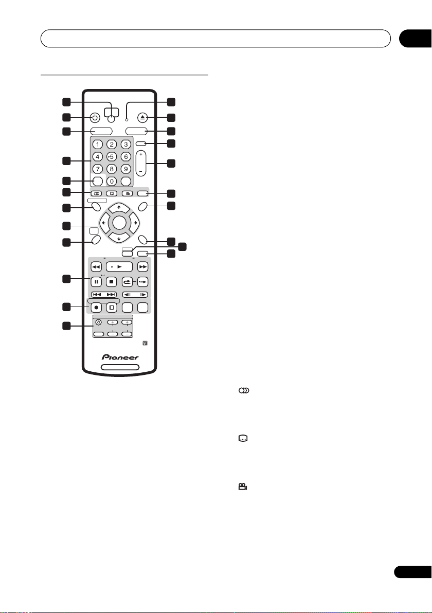
Remote control
1 2
STANDBY/ON
ONE TOUCH
3
5
8
10
11
13
15
HDD DVD
GHI JKL MNO
PQRS TUV WXYZ
G
-CODE
+
AUDIO
DISC NAVIGATOR
TOP MENU
HOME
MENU
16
REV SCAN PLAY FWD SCAN
PAUSE STOP CM
20
21
22
PREV
REC
INPUT
SELECT
CASE
SELECTION
STOP REC
HDD/DVD RECORDER
1 ONE TOUCH COPY (page 79)
Press to start One Touch Copy of the
currently playing title to DVD or the HDD.
2 Remote control indicator
Lights when setting up the remote control
for use with a TV (page 132) and when
setting the remote control mode (page 118).
3 STANDBY/ON
Press to switch the recorder on/into standby.
4 OPEN/CLOSE
Press to open/close the disc tray.
5 HDD
Press to select the hard disk (HDD) for
recording or playback.
OPEN/CLOSE
COPY
INPUT
ABC
DEF
SELECT
CH
CLEAR
CLEAR
SUBTITLE ANGLE PLAY MODE
ENTER
RETURN
HELP
DISPLAY
OK BACK SKIP
NEXT STEP/SLOW
REC MODE TIMER REC
TVCONTROL
VOLUME
CHANNEL
4
6
7
9
12
MENU
14
17
18
19
6DVD
Press to select the DVD for recording or
playback.
7 INPUT SELECT (page 46)
Press to change the input to use for
recording.
8 Alphanumeric buttons, + and CLEAR
Use the number buttons for track/chapter/
title selection; channel selection, and so on.
The same buttons can also be used to enter
names for titles, discs and so on.
Use the + button to enter non-alphanumeric
characters and symbols.
Use CLEAR to clear an entry and start again.
9CH+/– (page 35)
Press to change the channel of the built-in
TV tuner.
10 G-Code™ (page 40)
Press then use the number buttons to enter
a G-Code programming number for timer
recording.
G-Code is a trademark of Gemstar
Development Corporation.
The G-Code system is manufactured
under license from Gemstar Development
Corporation.
11 DVD playback functions
AUDIO (page 35, 61)
Changes the audio language or channel.
(When the recorder is stopped, press to
change the tuner audio.)
SUBTITLE (page 60)
Press to display/change the subtitles
included in multilingual DVD-Video
discs.
ANGLE (page 62)
Press to switch camera angles on discs
with multi-angle scenes.
12 PLAY MODE (page 58)
Press to display the Play Mo de m en u (f or
features such as search, repeat and
programme play).
27
En

03
Controls and displays
13 DISC NAVIGATOR (page 55, 68)/
TOP MENU (page 52)
Press to display the Disc Navigator screen,
or the top menu if a DVD-Video or finalized
DVD-R/-RW (Video) disc is loaded.
14 MENU (page 52)
Press to display the disc menu if a DVDVideo disc is loaded.
15 /// and ENTER
Used to navigate all on-screen displays.
Press ENTER to select the currently
highlighted option.
16 HOME MENU
Press to display the Home Menu, from which
you can navigate all the functions of the
recorder.
17 RETURN
Press to go back one level in the on-screen
menu or display.
18 HELP
Press for help on how to use the current GUI
screen.
19 DISPLAY (page 62)
Displays/changes the on-screen information
displays.
20 Playback controls (page 51)
REV SCAN FWD SCAN
(page 57)
Press to start reverse or forward
scanning. Press again to change the
speed.
PLAY
Press to start playback.
PAUSE
Press to pause playback or recording.
STOP
Press to stop playback.
CM BACK (commercial back)
Press repeatedly to skip progressively
backward through the video playing.
CM SKIP (commercial skip)
Press repeatedly to skip progressively
forward through the video playing.
PREV NEXT
Press to skip to the previous or next title/
chapter/track; or to display the previous
or next menu page.
STEP/SLOW (page 57)
During playback, press to start slowmotion playback; while paused, press to
show the previous or next video frame.
21 Recording controls (page 37)
REC
Press to start recording. Press
repeatedly to set the recording time in
blocks of 30 mins.
F STOP REC
Press to stop recording.
REC MODE (page 36)
Press repeatedly to change the
recording mode (picture quality).
TIMER REC (page 38)
Press to start setting a timer recording.
22 TV CONTROL (page 132)
After setting up, use these controls to
control your TV.
28
En
Getting started
Chapter 4
Getting started
04
Switching on and setting up
When you switch the recorder on for the first
time, you can make several basic settings
using the Setup Navigator feature. This takes
you through setting the clock, the internal TV
tuner and the video output.
If you’re using the recorder for the first time,
we strongly recommend you use the Setup
Navigator before starting to use the
recorder.
Important
• Some of the Setup Navigator on-screen
displays (OSDs) in this section vary
slightly depending on the country or
region of purchase.
• Unless otherwise stated, the OSDs
shown in this manual are for the Taiwan
and Philippines model.
1 Switch on your TV and set the video
input to this recorder.
STANDBY/ON
2 Switch on the recorder.
When you switch on for the first time, your TV
should display the Setup Navigator screen (If
the Setup Navigator doesn’t appear, you can
also access it from the Initial Setup menu;
see page 108).
ENTER
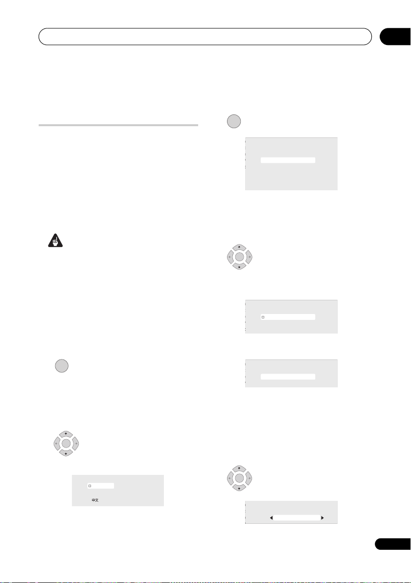
3 Choose a language (then
press ENTER).
Language
English
Español
Italiano
Português
ENTER
4 Start the Setup Navigator.
Setting
Complete this setup before you
Line System
start using your recorder.
r Save
Start
Start
Cancel
Navigator
Navigator
Please use the Initial Setup if you
want to make more detailed settings.
• If you don’t want to use the Setup
Navigator, press to select Cancel,
then press ENTER to exit the Setup
Navigator.
ENTER
5 Select an option then press
ENTER.
Taiwan and Philippines model:
Setting
Auto Channel Setting
Line System
r Save
English
Antenna
Cable
Navigator
Do not Set
Navigator
Other:
Setting
Auto Channel Setting
Line System
r Save
English
Auto Scan
Do not Set
• Select Do not set if you want to skip
channel setup (because they have
already been set up, for example).
• You can go back to the previous screen
in the Setup Navigator by pressing
RETURN.
ENTER
• Select your country.
Setting
Setting
Country Selection
Line System
Line System
r Save
r Save
Country
Singapore
29
En

04
Getting started
• Auto-tuning channels
The Auto Scan option automatically scans
and sets the channel presets.
Tuning
32/68
Cancel
ENTER
6 Select ‘Auto’ for automatic
time setting, or ‘Manual’ to set the clock
manually.
Setting
Clock Setting
Line System
Auto
r Save
Auto
Manual
• Auto clock setting
Some TV channels broadcast time
signals together with the programme.
This recorder can use these signals to
set the clock automatically.
Set ‘Clock Set CH‘ to the channel
preset number that broadcasts a time
signal, then move the cursor down to
‘Start’ and press ENTER.
Setting
Auto Clock Setting
Line System
Date
r Save
Time
Navigator
Navigator
Clock Set CH
–– / –– / ––––
–– : –– AM
2
Start
The recorder takes a short while to set
the time. After you see that it’s set, select
Next to proceed.
Setting
Auto Clock Setting
Line System
Date
Time
Clock Set CH
1 / 01 / 2007 MON
12 : 00 AM
2
Start
Next
r Save
Navigator
Navigator
If the time could not be set
automatically, press RETURN to go back
to the previous screen and select
Manual.
• Manual clock setting
If no stations in your area are
broadcasting time signals, you can set
the clock manually.
Use the / buttons to set your
time zone.
You can set this by selecting a city or a
time relative to GMT.
Setting
Manual Clock Setting
Line System
Time Zone
r Save
Navigator
D.S.T
Navigator
Singapore
Singapore
Off
1/2
Press then use the / buttons to
select ‘On’ or ‘Off’ for daylight
saving/summer time, then press
ENTER.
Select On if you are currently using
daylight saving/summer time.
Setting
Manual Clock Setting
Line System
Time Zone
r Save
Navigator
D.S.T
Navigator
Singapore
Singapore
On
1/2
Set the date and time, then press
ENTER to make all the settings.
Taiwan and Philippines model: The date
is in month/day/year format.
Other: The date is in day/month/year
format.
Setting
Manual Clock Setting
Line System
Date
r Save
Time
Navigator
Navigator
Time Zone
D.S.T
1/ /01
12 : 00 AM
Singapore
Singapore
On
2/2
2007 MON
•Use the / buttons to change the
value in the highlighted field.
•Use the / buttons to move from one
field to another.
• Press ENTER to finish setting the time.
30
En
 Loading...