

Pioneer DVR-541-HS Schematic

DVD RECORDER
DVR-541H-S
THIS MANUAL IS APPLICABLE TO THE FOLLOWING MODEL(S) AND TYPE(S).
Serial No.
Model Type Power Requirement Region No. Please confirm 3rd & 4th
alphabetical letters.
DVR-541H-S RDRXV AC 110 V to 127 V / 220 V to 240 V 4 &&DL######$$
ORDER NO.
RRV3461
This service manual should be used together with the following manual(s):
Model
DVR-640H-S/KUCXV
RRV3376
RemarksOrder No.
CONTENTS
1. CONTRAST OF MISCELLANEOUS PARTS
2. GENERAL INFORMATION
2.1 MODEL TYPE SETTING
2.2 DV DEBUG MODE
3. SCHEMATIC DIAGRAM
4. PCB CONNECTION DIAGRAM
PIONEER CORPORATION 4-1, Meguro 1-chome, Meguro-ku, Tokyo 153-8654, Japan
PIONEER ELECTRONICS (USA) INC. P.O. Box 1760, Long Beach, CA 90801-1760, U.S.A.
PIONEER EUROPE NV Haven 1087, Keetberglaan 1, 9120 Melsele, Belgium
PIONEER ELECTRONICS ASIACENTRE PTE. LTD. 253 Alexandra Road, #04-01, Singapore 159936
PIONEER CORPORATION 2006
...................................
.................................
...........................................
.....................................
..........................
........
2
6
6
7
10
22
T – ZZV JULY 2006 Printed in Japan
1
jpfy
23
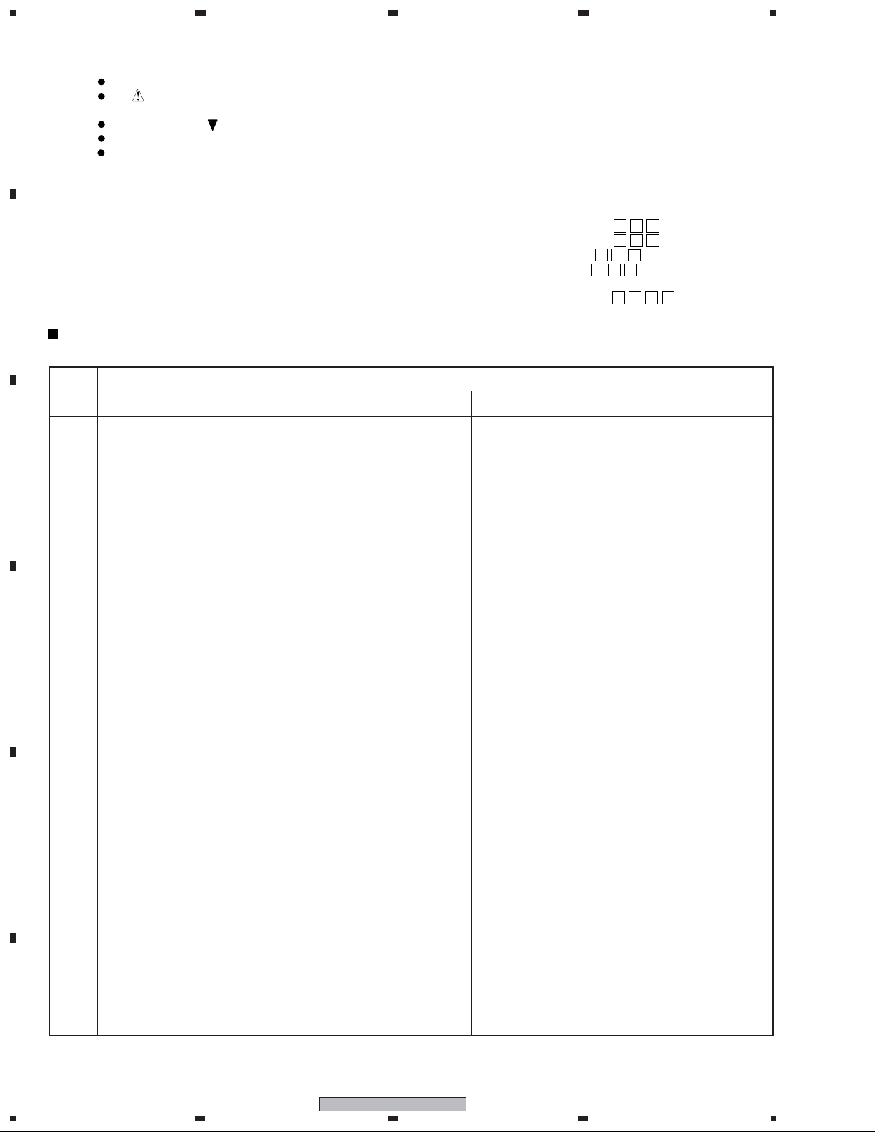
1. CONTRAST OF MISCELLANEOUS PARTS
NOTES:
A
B
CONTRAST TABLE
DVR-541H-S/RDRXV and DVR-540H-S/KUCXV are constructed the same except for the following :
Parts marked by "NSP" are generally unavailable because they are not in our Master Spare Parts List.
The mark found on some component parts indicates the importance of the safety factor of the part.
Therefore, when replacing, be sure to use parts of identical designation.
Screws adjacent to mark on product are used for disassembly.
Reference Nos. indicate the pages and Nos. in the service manual for the base model.
For the applying amount of lubricants or glue, follow the instructions in this manual.
(In the case of no amount instructions, apply as you think it appropriate.)
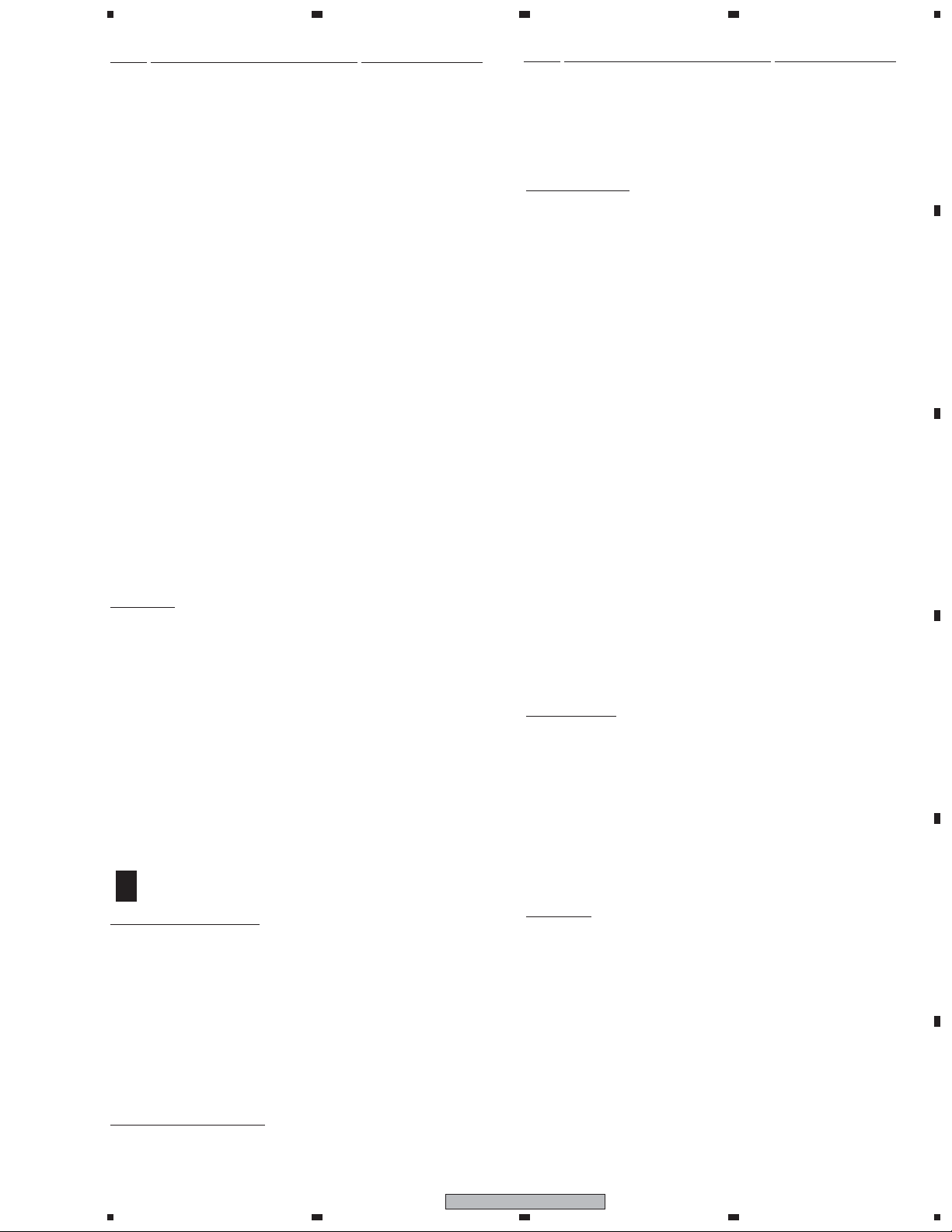
When ordering resistors, first convert resistance values into code form as shown in the following examples.
•
Ex.1 When there are 2 effective digits (any digit apart from 0), such as 560 ohm and 47k ohm (tolerance is shown by J=5%,
and K=10%).
560 Ω→56 × 10
47k Ω→47 × 10
1
→ 561 ........................................................ RD1/4PU 5 6 1 J
3
→ 473 ........................................................ RD1/4PU 4 7 3 J
0.5 Ω→R50 ..................................................................................... RN2H
1 Ω→1R0 ..................................................................................... RS1P
Ex.2 When there are 3 effective digits (such as in high precision metal film resistors).
5.62k Ω→ 562 × 10
1
→ 5621 ...................................................... RN1/4PC 5 6 2 1 F
R 5 0
1 R 0
4
K
K
Ref.
Mark Symbol and Description
No.
PCB ASSEMBLIES
NSP 1..TUJB ASSY VWM2362 VWM2368
C
D
P11- 1 3..TUJB ASSY (for Service) VXX3146 VXX3150
P11- 3 1..MAIN ASSY (for Service) VXX3159 VXX3161
P11- 6 > 1.. POWER SUPPLY UNIT VWR1401 VWR1400 No service part
P9- 1 > Power Cord ADG7021 ADG7003
P9- 4 Remote Control Unit VXX3095 VXX2964
P9- 5 Battery Cover VZN1004 AZA7424
P9- 6 Top Cover VZN1012 Not used
P9- 8 NSP Warranty Card ARY7045 Not used
P9- 9 Operating Instructions (English) VRB1412 VRB1417
P9-10 Operating Instructions (French) VRC1318 Not used
P9-11 Quick Start Guide VRG1014 Not used
P9-12 Quick Start Guide VRL1012 Not used
P9-18 Packing Case VHG2726 VHG2750
NSP 2..TUJB AI VWV2168 VWV2168
1..DVJB ASSY Not used VWV2160 No.1
PACKING SECTION
> Power Cord Not used XDG3009
Operating Instructions (Spanish) Not used VRC1328
Operating Instructions (Portuguese) Not used VRC1365
DVR-540H-S/KUCXV
Part No.
DVR-541H-S/RDRXV
Remarks
EXTERIOR SECTION
E
F
P11- 7 HDD 80G ST3802110 VXF1108 Not used
P11- 7 HDD 160G ST3160212 Not used VXF1110
Flexible Cable(24P) Not used VDA2111 No.2
DV Angle Not used VNE2426 No.3
Screw Not used VBA1088 No.4
P11-22 Rear Panel VNA2870 VNA2927
P11-32 Rubber Spacer VEB1389 VEB1380
FRONT PANEL SECTION
P13-12 Front Panel VNK5966 VNK6052
P13-14 FL Lens PTD VXA2740 VXA2808
P13-15 Door PTD VXA2776 VXA2807
Notes : • For PCB ASSEMBLIES, Refer to “CONTRAST OF PCB ASSEMBLIES”,“PCB PARTS LIST”, “3. SCHEMATIC DIAGRAM”
and “4. PCB CONNECTION DIAGRAM”..
• The numbers in the remarks column correspond to the numbers on "EXTERIOR SECTION".
2
1234
DVR-541H-S

1
EXTERIOR SECTION
MAIN
CN3802
B
4
3
CONTRAST OF PCB ASSEMBLIES
2
A
I
F
A
1
A : BBZ30P060FTC
B : BSZ30P040FTC
234
A
B
Chassis
TUJB ASSY
A
F
VXX3150 and VXX3146 are constructed the same except for the following :
Mark Symbol and Description
VXX3146 VXX3150
R170 RD1/4PU393J Not used
R172 RD1/4PU682J RD1/4PU333J
R173 RD1/4PU393J RD1/4PU333J
R174 RD1/4PU682J RD1/4PU473J
Part No.
C
Remarks
D
E
F
DVR-541H-S
1
2
3
4
3

1
PCB PARTS LIST
Mark No. Description Part No.
A
MAIN ASSY
E
F
SEMICONDUCTORS
IC3101 AK5359ET
IC501 BD7997FS
> IC2401, IC2402 CEK1285
IC1201, IC1221 K4H511638C-UCB3
IC2202 MM1501XN
IC2201 MM1503XN
IC1301 NJM12904V
IC3802 PCA9557PW
IC3201 PCM1742KE
B
C
IC3707 PST3813U
> IC4512 S-1170B25UC-OTK
> IC4507, IC4511 S-1170B33UC-OTS
> IC4504 S-1170B50UC-OUJ
IC3103 TC74VHC157FT
IC3102 TC7SZ126FU
IC3701 TC7WH34FU
IC101 UPC3345GC-YEB-A
IC3202 UPC4570G2-A
IC1001 UPD61272F1-107KA3A
IC1102 VYW2366
Q1801, Q1811, Q2205, Q2206 2SA1576A
Q2501-Q2505 2SA1576A
Q3501, Q4561 2SC4081
Q101 RT1N141U
D3201 DAN202U
D3711, D3712 RB501V-40
D101 SML-310YT
COILS AND FILTERS
L1010, L106, L107, L112 CHIP COIL BTH1103
L1001, L1003, L1004, L1006-L1008 DTL1106
L1201, L3102, EMI FILTER DTL1106
D
L1811 LCYA150J2520
L1801 LCYA390J2520
CAPACITORS
C1081 CCSSCH100D50
C158-C162, C1813 CCSSCH101J50
C3207, C3211 CCSSCH121J50
C1902, C1911 CCSSCH150J50
C1812 CCSSCH151J50
C1901, C1912 CCSSCH180J50
C1803 CCSSCH221J50
C169, C171, C509 CCSSCH390J50
E
F
C3501, C3808-C3810 CCSSCH470J50
C1084-C1087 CCSSCH5R0C50
C510 CCSSCH620J50
C264 CCSSCH680J50
C3212 CEAT102M6R3
C1708, C4507 CEVW100M16
C2506, C3106, C3214, C3216, C4542 CEVW101M16
C4563, C5624 CEVW101M16
C1001, C1003, C1005, C1014, C1020 CEVW221M4
C1071, C1074, C1235, C5701 CEVW221M4
C511 CKSQYB105K16
C105, C1073, C1076, C121-C123 CKSQYB475K6R3
C125, C133, C135, C152, C153 CKSQYB475K6R3
23
Mark No. Description Part No.
C155, C165, C168, C178, C181 CKSQYB475K6R3
C184, C4508, C4525, C4526 CKSQYB475K6R3
C4548, C4549, C4552, C5725 CKSQYB475K6R3
C157, C2221, C2222, C4551 CKSRYB105K10
C109, C111 CKSRYB334K10
C101, C102, C136 CKSRYB474K10
C1009, C1015, C1018, C1021, C1024 CKSRYF105Z10
C1044, C1047, C1052, C1055 CKSRYF105Z10
C1061, C1062, C1065, C1070, C1113 CKSRYF105Z10
C1202, C1204, C1208, C1221, C1223 CKSRYF105Z10
C1227, C1421, C1801, C1811 CKSRYF105Z10
C2208, C2209, C2501, C296 CKSRYF105Z10
C3102, C3103, C3107, C3511, C3703 CKSRYF105Z10
C3738, C3801-C3805, C5621, C5702 CKSRYF105Z10
C1010, C1016, C1019, C1022, C1025 CKSSYB102K50
C1046, C1049, C1054, C1057, C1059 CKSSYB102K50
C1064, C1067, C1068, C1207 CKSSYB102K50
C1209, C1210, C1226, C1228, C1229 CKSSYB102K50
C151, C189, C261, C4527, C4550 CKSSYB102K50
C119, C1205, C1206, C1224, C1225 CKSSYB103K16
C129, C130, C142, C164, C1709 CKSSYB103K16
C187, C188, C221, C2223, C2224 CKSSYB103K16
C3701, C4509 CKSSYB103K16
C1026, C1029, C103, C1034, C1037 CKSSYB104K10
C104, C1040, C1043, C112, C117 CKSSYB104K10
C124, C126-C128, C132 CKSSYB104K10
C143, C144, C150, C156, C163 CKSSYB104K10
C167, C172, C175, C2301, C2302 CKSSYB104K10
C260, C3806, C3815, C3816 CKSSYB104K10
C504, C505 CKSSYB104K10
C137 CKSSYB182K50
C145, C146 CKSSYB222K50
C224, C230, C231 CKSSYB223K16
C108, C110, C139, C141, C1802 CKSSYB331K50
C3204 CKSSYB331K50
C114 CKSSYB332K50
C116 CKSSYB333K10
C232, C233 CKSSYB471K50
C148, C220, C223 CKSSYB472K25
C147, C1804, C1814, C532 CKSSYB473K10
C297, C3208, C3210 CKSSYB681K50
C138 CKSSYB682K25
C154, C236 CKSSYB683K10
C115 CKSSYB822K16
C1002, C1004, C1007, C1045, C1048 CKSSYF104Z16
C1050, C1051, C1053, C1056, C1058 CKSSYF104Z16
C1060, C1063, C1066, C1069, C1082 CKSSYF104Z16
C1105, C1203, C1211-C1214, C1222 CKSSYF104Z16
C1230, C1302, C1303, C1312, C1313 CKSSYF104Z16
C1701-C1707, C2401-C2406, C3101 CKSSYF104Z16
C3108, C3201-C3203, C3206, C3209 CKSSYF104Z16
C4561, C4562, C4565, C501, C503 CKSSYF104Z16
C113 (2.2/10) DCG1040
C502 (10/16) DCH1165
C1008, C1017, C107, C1075, C118 DCH1201
C2210, C2217, C5727-C5729 (10/10) DCH1201
C1215 (150/4) VCH1246
RESISTORS
R501 (0.47/1/4W) DCN1160
4
4
1234
DVR-541H-S
1
234
Mark No. Description Part No.
R502 (0.68/1/4W) DCN1162
R3854 RAB4CQ0R0J
R1411, R240, R3005, R3102, R3707 RAB4CQ103J
R3801-R3806 RAB4CQ223J
R1245, R1246, R1255, R1256 RAB4CQ330J
R1265, R1266, R1273, R1274 RAB4CQ330J
R3810-R3813, R3824 RAB4CQ330J
R254 RAB4CQ473J
R1241, R1242, R1248, R1249 RAB4CQ560J
R1261, R1262, R1268, R1269 RAB4CQ560J
R1281-R1283, R1287 RAB4CQ560J
R3208, R3223 RN1/16SC56R0D
R3207, R3226 RN1/16SE1502D
R3209, R3224 RN1/16SE8201D
R1001, R1002, R133, R2401 RS1/10S0R0J
R4513, R4514, R4517, R4520-R4524 RS1/10S0R0J
R4527, R4591-R4593, R5702 RS1/10S0R0J
R1302, R1303, R1312, R1313 RS1/16S1001F
R5714 RS1/16S1501F
R2502, R2505, R2508, R2511, R2514 RS1/16S2000F
R1301 RS1/16S4700F
R1052 RS1/16S6200F
R3505 RS1/16S75R0F
R1054 RS1/16S9100F
R181 RS1/16SS4701F
R510, R511 RS1/4SA2R0J
R115, R1003-R1008, R1314, R2506 RS1/16S###J
R3837, R3850 RS1/16S###J
Other Resistors RS1/16SS###J
OTHERS
CN502 4P CONNECTOR DKN1288
CN501 D-SOCKET(14P) DKN1312
CN601 5P CONNECTOR DKN1402
CN101 CONNECTOR DKN1404
X201 (16.93MHz) OSC DSS1152
Mark No. Description Part No.
L106, L107 EMI FILTER DTL1106
L101, L102 LCYA100J2520
L109, L111 LCYA150J2520
L108, L110 LCYA180J2520
L104, L105 COIL VTH1043
CAPACITORS
C200, C218 CCSRCH100D50
C258 CCSRCH271J50
C211, C213 CCSRCH330J50
C212 CCSRCH5R0C50
C254, C255 CCSRCH8R0D50
C107, C112 CCSSCH330J50
C161-C163 CCSSCH470J50
C103, C108 CCSSCH680J50
C104, C109 CCSSCH7R0D50
C106, C111 CCSSCH820J50
C105, C110 CCSSCJ3R0C50
C144, C220, C223 CEVW221M4
C101, C102, C122, C126, C140 CKSQYF106Z10
C142, C147, C204, C207, C214 CKSQYF106Z10
C230, C233, C248, C252 CKSQYF106Z10
C222 CKSQYF475Z10
C201, C205 CKSRYB104K16
C203, C210, C245, C249, C250 CKSRYF104Z25
C124, C127-C135, C141, C143 CKSRYF105Z10
C146, C148-C160, C206, C215 CKSRYF105Z10
C231, C240, C241, C243, C244 CKSRYF105Z10
C246, C247, C251, C253 CKSRYF105Z10
C256, C257 CKSRYF105Z10
C216 CKSRYF473Z25
C145, C235 CKSSYB103K16
C113-C117, C123, C125, C136 CKSSYF104Z16
C232, C234, C237, C242 CKSSYF104Z16
C259-C261 CKSSYF104Z16
A
B
C
CN1402 07P CONNECTOR RKN1048
CN2401 KR CONNECTOR S13B-PH-K
CN2301 35P CONNECTOR VKN1439
CN401 CONNECTOR VKN202
CN1401 CONNECTOR VKN2030
CN3802 CONNECTOR VKN2045
CN3801 CONNECTOR VKN2050
X1002 (27MHz) CRYSTAL VSS1191
X1001 (24.576MHz) CRYSTAL VSS1192
I
F
DVJB ASSY
SEMICONDUCTORS
IC101 ADV7172KSTZ
IC103 HY57V161610ETP-8
IC105, IC107 NJU7013F
> IC106 S-1170B25UC-OTK
IC104 TC7WHU04FU
IC108 UPD72852AGB-8EU-A
IC102 UPD72893BF1-FN3
Q101-Q104 2SA1576A
D101 HVC359
D102 HVC362
COILS AND FILTERS
F101 CHIP COIL DTF1069
RESISTORS
R144-R149, R155-R158 RAB4CQ103J
R169-R172, R185-R188 RAB4CQ103J
R150, R151 RAB4CQ470J
R248 RN1/16SE9101D
R141, R197, R198, R211, R215 RS1/10S0R0J
R105, R111 RS1/16S1500F
R268 RS1/16S5101F
R264-R267 RS1/16S56R0D
R135 RS1/16S6800F
Other Resistors RS1/16S###J
OTHERS
JA101 1394-TERMINAL VKN2028
CN101 CONNECTOR VKN2045
X102 ( 24.576MHz) CRYSTAL VSS1184
X101 (27.000MHz) VCXO VSS1195
D
E
F
DVR-541H-S
1
2
3
4
5
1
23
2. GENERAL INFORMATION
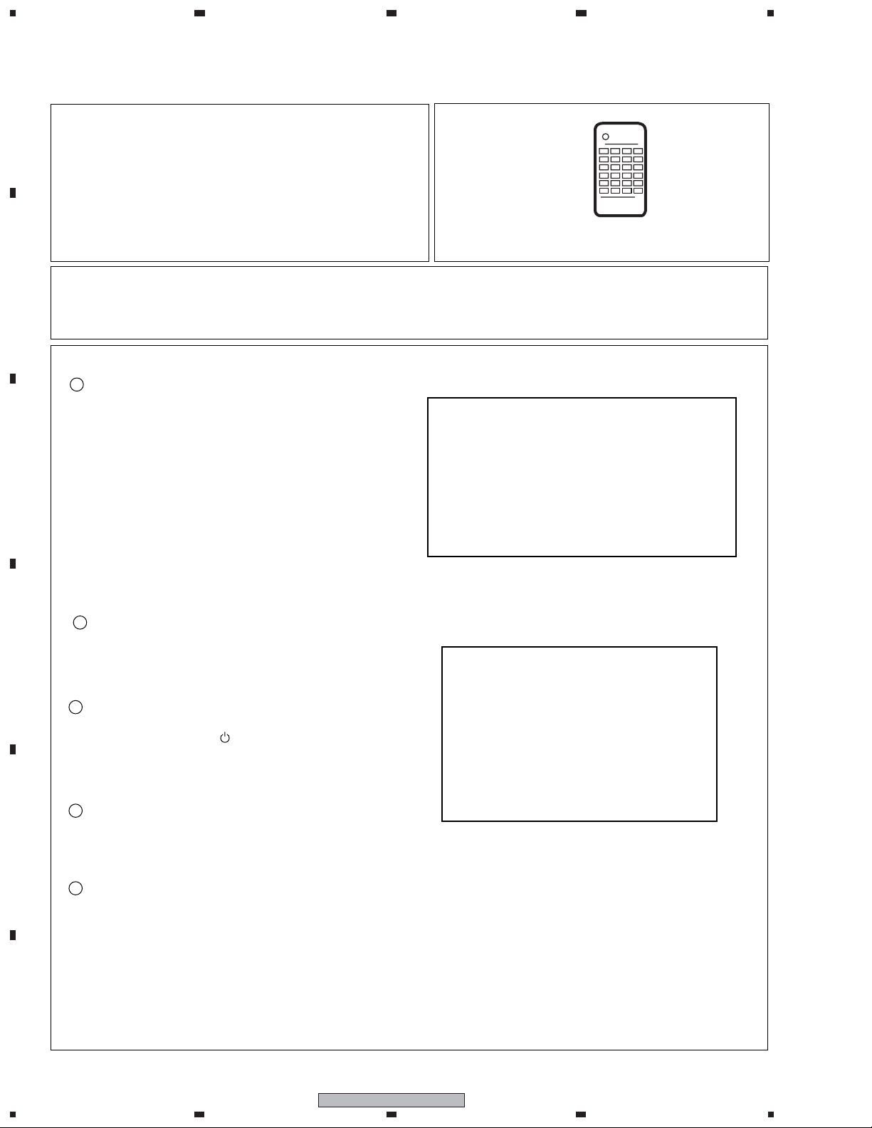
2.1 MODEL TYPE SETTING
A
[Purposes]
When the MAIN Assy and/or TUJB Assy that are(is)
commonly used with another model are(is) replaced,
they(it) must recognize the model of this unit.
Items to be set: The model number, destination, and
region No. must be set.
4
[Tool to be used]
Remote control unit for servicing
(GGF1381)
B
[Notes]
• Once the setting has been made, it can never be changed. Be sure to make the setting correctly.
• As this setting resets the Assy(s) in question to the factory-preset status, it is recommended that you obtain
the customer's consent beforehand.
[Procedures]
1
After power on, the following screen is displayed on
TV monitor. Press four digits properly (" 0209 ") by
using the remote control unit for service,according to
the screen information.
C
2
Disconnect then reconnect the AC power cord of the
unit. Be careful not to impart vibration to the unit
D
immediately after the AC power cord is disconnected.
Reset the recorder to all its factory settings.
3
(Make sure that the recorder is on. Press and hold 7
(STOP) key and press (STANDBY/ON) key on the
front panel.)
The recorder turns off with all settings reset.
4
Press [ESC] then [DISP] keys by using the remote
control unit for servicing, and then confirm each
E
Model Name (" DVR-541H/RDR ").
[Recorder's Model Setting]
Input the number using the remote for Service.
> - - -
Input No. Model
[ 0208 : DVR-541H/RF ]
[ 0209 : DVR-541H/RDR ]
DVR-541H/RDR VERSION : 1.∗∗
SYSCON : RELEASE_100
TUNERCON : 198.000 OK
DRIVE : DVD-RW DVR-L11X OK
1.00 OK
HDD : WDC WD1600BB-xxJKCx 160
DEVICE : E2R-FE 1.2 FLASH : 64M
REGION : 4 C : ∗ ∗ ∗ ∗ ∗ ∗ ∗ ∗ ∗
Rev :1.1000
End
5
F
6
1234
DVR-541H-S
1
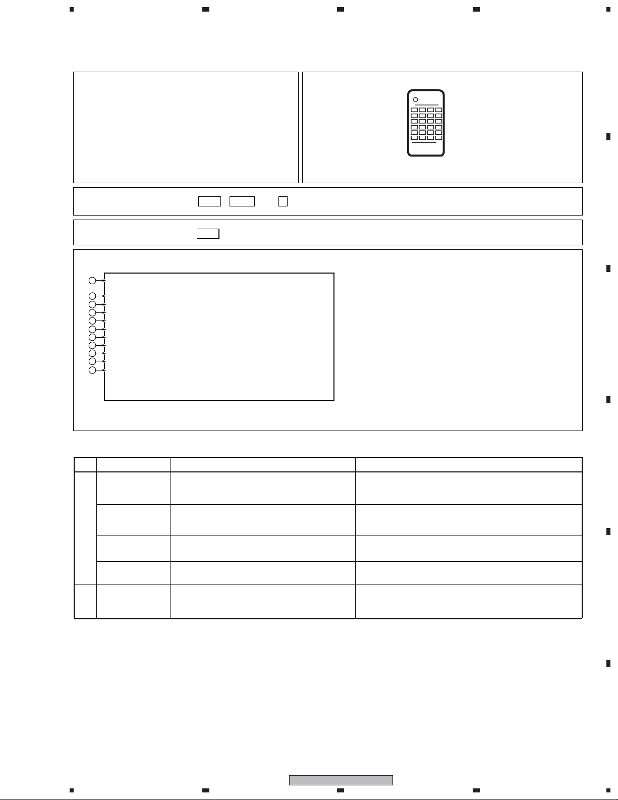
2.2 DV DEBUG MODE
234
1. DV debug
[
Purpose
] [Tools to be used]
To check whether communication
between a DV device and the unit is
normal when a DV device is connected
How to enter
[
[
How to quit
]
]
[Mode description]
(DV/1394) InitDV:OK InitVE:OK AV:02 DV:01
1
[Recorder] GUID:00E0360006100001 IRM
2
iPCR:C03F0000 oPCR:0000007A
3
[DV] GUID:0080880303480E96
4
VN:VICTOR MN:GR-D50K
5
TM:C3 TS:75 CT:32 WP:01 PS:FF OS:00
6
CA:A000002020 CV:FF MD:VTR
7
[DVdecode:Yes] LineSys:525-60
8
9
TC:00h20m35s RD:02/02/05 RT:10h34m50s
10
ASPECT:4:3 CGMS:000000 APSTB:00 DEC:525-60
SF:32KHz QU:12bit AMODE:4) Stereo
11
Press the ESC , DISP then 3 keys, in that order.
Press the ESC key.
Remote control unit for servicing
(GGF1381)
A
• DV device
• DV cable
B
C
Boldface alphanumerics : Fixed indications
Nonboldface alphanumerics : Variable indications
No. Item Description Remarks
InitDV
1
InitVE
AV Number of AV devices recognizing connection
DV Number of DV devices recognizing connection
GUID
2
Whether the initialization of UPD72893B(1394
LINK and DV codec IC) has been completed (OK)
or not (NG)
Whether the initialization of ADV7172 (Video
Encoder for DV specific) has been completed (OK)
or not (NG)
GUID set in ConfigROM of the unit
If NG is displayed, it is considerd the communication failure to
UPD72893B.
If NG is displayed, it is considerd the communication failure to
ADV7172.
Identification number of AV devices including D-VHS, Digital
Tuner, etc other than DV devices.
If the number does not become 01 even if a DV device is
connected, identification of that device fails.
GUID : Global Unique ID (Specific ID for DV devices)
If the unit is ROOT (IRM), IRM is displayed at the side position
of GUID display.
D
E
F
DVR-541H-S
1
2
3
4
7
1
23
4
No. Item Description Remarks
A
B
C
iPCR
3
oPCR
GUID
4
VN
5
MN
TM Transport Mode data obtained from the DV device
TS Transport State data obtained from the DV device
CT Cassette Type data obtained from the DV device
6
WP Write-protection data obtained from the DV device
PS Power-state data obtained from the DV device
OS
CA Connect AV data obtained from the DV device
CV
7
MD
8
[DVdecode:XXX]
LineSys Input Line System setting
TC
9
RD Rec Date of DVdecode Stream
RT Rec Time of DVdecode Stream
ASPECT Aspect Ratio of DVdecode Stream
iPCR value of the unit
oPCR value of the unit
GUID set in ConfigROM of the connected DV device
Vendor name set in ConfigROM of the connected
DV device
Model name set in ConfigROM of the connected
DV device
Output signal mode data obtained from the DV
device
Camera/Vtr mode data obtained from the DV device
DV device mode
Whether Yes (in the process of requesting DV
input) or No is indicated in XXX
Time-code data of the DVdecode Stream, or
response data of the Time Code command
Data are displayed only if one DV device is identified.
If the connectd DV device is ROOT (IRM), IRM is displayed at
the side position of GUID display.
Data are displayed only if one DV device is identified.
(Depending on the device, the vendor name may not be set in
ConfigROM.)
Data are displayed only if one DV device is identified.
(Depending on the device, the model name may not be set in
ConfigROM.)
Data are displayed only if one DV device is identified.
Data are displayed only if one DV device is identified.
Camera or VTR is displayed only if one DV device is
identified.
Normally, Yes is indicated only when CH is set to DV.
Stream time-code data are obtained when the tape is
played in forward direction. Otherwise, time-code data
are obtained through an AV/C command.
D
E
F
CGMS
0
APSTB APS trigger bit of DVdecode stream
DEC
SF
-
QU QUANTIZATION of DVdecode Stream
AMODE AUDIO MODE of DVdecode Stream
CGMS of DVdecode Stream (from left to right,
CGMS data of bits 5-4: Audio ch 2, bits 3-2:
Audio ch 1, and bits 1-0: Video)
With/without DVdecode stream input
Sampling Frequency of DVdecode Stream
*CGMS (Copy Generation Management System): The
two-digit codes added to broadcast programs represent
the following:
00: Copy freely, 10: Once copy, 11: Never copy
With input: Signal type (525-60, 625-50, 1125-60, 125050, or Invalid) is indicated, Without input: "No" is
indicated.
If SF is 44 kHz, it is considered that 44.1-kHz audio is
input, and sound is muted on the unit.
8
1234
DVR-541H-S
 Loading...